JP6333476B2 - Clothing steaming device with valve assembly for fragrance cartridge - Google Patents
Clothing steaming device with valve assembly for fragrance cartridge Download PDFInfo
- Publication number
- JP6333476B2 JP6333476B2 JP2017519287A JP2017519287A JP6333476B2 JP 6333476 B2 JP6333476 B2 JP 6333476B2 JP 2017519287 A JP2017519287 A JP 2017519287A JP 2017519287 A JP2017519287 A JP 2017519287A JP 6333476 B2 JP6333476 B2 JP 6333476B2
- Authority
- JP
- Japan
- Prior art keywords
- cavity
- steam
- valve
- steaming device
- cartridge
- Prior art date
- Legal status (The legal status is an assumption and is not a legal conclusion. Google has not performed a legal analysis and makes no representation as to the accuracy of the status listed.)
- Active
Links
- 239000003205 fragrance Substances 0.000 title claims description 81
- 238000010025 steaming Methods 0.000 title claims description 60
- 230000002093 peripheral effect Effects 0.000 claims description 34
- 230000001186 cumulative effect Effects 0.000 claims description 3
- 230000001419 dependent effect Effects 0.000 claims description 2
- 230000002452 interceptive effect Effects 0.000 claims 1
- XLYOFNOQVPJJNP-UHFFFAOYSA-N water Substances O XLYOFNOQVPJJNP-UHFFFAOYSA-N 0.000 description 9
- 239000000341 volatile oil Substances 0.000 description 7
- XEEYBQQBJWHFJM-UHFFFAOYSA-N Iron Chemical compound [Fe] XEEYBQQBJWHFJM-UHFFFAOYSA-N 0.000 description 6
- 239000007788 liquid Substances 0.000 description 4
- 239000011148 porous material Substances 0.000 description 4
- 229910052742 iron Inorganic materials 0.000 description 3
- 238000007789 sealing Methods 0.000 description 3
- 235000019568 aromas Nutrition 0.000 description 2
- 238000010409 ironing Methods 0.000 description 2
- 239000000654 additive Substances 0.000 description 1
- 238000004891 communication Methods 0.000 description 1
- 239000007799 cork Substances 0.000 description 1
- 238000010586 diagram Methods 0.000 description 1
- 239000013013 elastic material Substances 0.000 description 1
- 239000004744 fabric Substances 0.000 description 1
- 239000012530 fluid Substances 0.000 description 1
- 239000006260 foam Substances 0.000 description 1
- 238000003780 insertion Methods 0.000 description 1
- 230000037431 insertion Effects 0.000 description 1
- 239000002304 perfume Substances 0.000 description 1
- 238000005507 spraying Methods 0.000 description 1
Images


Classifications
-
- D—TEXTILES; PAPER
- D06—TREATMENT OF TEXTILES OR THE LIKE; LAUNDERING; FLEXIBLE MATERIALS NOT OTHERWISE PROVIDED FOR
- D06F—LAUNDERING, DRYING, IRONING, PRESSING OR FOLDING TEXTILE ARTICLES
- D06F75/00—Hand irons
- D06F75/08—Hand irons internally heated by electricity
- D06F75/10—Hand irons internally heated by electricity with means for supplying steam to the article being ironed
- D06F75/14—Hand irons internally heated by electricity with means for supplying steam to the article being ironed the steam being produced from water in a reservoir carried by the iron
-
- D—TEXTILES; PAPER
- D06—TREATMENT OF TEXTILES OR THE LIKE; LAUNDERING; FLEXIBLE MATERIALS NOT OTHERWISE PROVIDED FOR
- D06F—LAUNDERING, DRYING, IRONING, PRESSING OR FOLDING TEXTILE ARTICLES
- D06F73/00—Apparatus for smoothing or removing creases from garments or other textile articles by formers, cores, stretchers, or internal frames, with the application of heat or steam
-
- D—TEXTILES; PAPER
- D06—TREATMENT OF TEXTILES OR THE LIKE; LAUNDERING; FLEXIBLE MATERIALS NOT OTHERWISE PROVIDED FOR
- D06F—LAUNDERING, DRYING, IRONING, PRESSING OR FOLDING TEXTILE ARTICLES
- D06F87/00—Apparatus for moistening or otherwise conditioning the article to be ironed or pressed
-
- D—TEXTILES; PAPER
- D06—TREATMENT OF TEXTILES OR THE LIKE; LAUNDERING; FLEXIBLE MATERIALS NOT OTHERWISE PROVIDED FOR
- D06F—LAUNDERING, DRYING, IRONING, PRESSING OR FOLDING TEXTILE ARTICLES
- D06F75/00—Hand irons
-
- D—TEXTILES; PAPER
- D06—TREATMENT OF TEXTILES OR THE LIKE; LAUNDERING; FLEXIBLE MATERIALS NOT OTHERWISE PROVIDED FOR
- D06F—LAUNDERING, DRYING, IRONING, PRESSING OR FOLDING TEXTILE ARTICLES
- D06F75/00—Hand irons
- D06F75/08—Hand irons internally heated by electricity
- D06F75/24—Arrangements of the heating means within the iron; Arrangements for distributing, conducting or storing the heat
-
- D—TEXTILES; PAPER
- D06—TREATMENT OF TEXTILES OR THE LIKE; LAUNDERING; FLEXIBLE MATERIALS NOT OTHERWISE PROVIDED FOR
- D06F—LAUNDERING, DRYING, IRONING, PRESSING OR FOLDING TEXTILE ARTICLES
- D06F79/00—Accessories for hand irons
Description
本発明は、衣類スチーミングデバイス(garment steaming device)に関し、特に、芳香カートリッジ(fragrance cartridge)のためのバルブアセンブリを備えるスチーミングデバイスに関する。 The present invention relates to a garment steaming device, and more particularly to a steaming device comprising a valve assembly for a fragrance cartridge.
衣類内に芳香をアイロン掛けすること(ironing)が長期の時間期間に亘って衣類から放出される芳香をもたらすことが知られている。例えば、アイロン掛け前に衣類に芳香液を事前に吹き付け得る。しかしながら、衣類に事前に吹き付けるのは時間がかかり、芳香液が衣類に染みをつけることがある。 It is known that ironing a fragrance within a garment results in a fragrance released from the garment over an extended period of time. For example, a fragrance can be pre-sprayed onto clothing before ironing. However, pre-spraying clothing takes time and the fragrance may stain the clothing.
芳香は、芳香付き精油の滴をスチームアイロン(steam iron)の水タンク内に注入することによって、衣類に加えられてもよい。従って、スチームアイロンが作動させられるとき、水タンク内の液体水は気化させられ、精油の芳香が付与される。しかしながら、使用者がどれぐらいの精油が水タンクに加えられるべきかを判断するのは困難である。更に、水タンク内の精油は水と共に蒸発せず、精油の殆どは水タンク内に残り、よって、スチーム(蒸気)は強い芳香を有さない。加えて、異なる芳香が用いられる前に、水タンクから液体水及び精油を出す必要がある。 The fragrance may be added to the garment by injecting a drop of fragrant essential oil into the water tank of the steam iron. Thus, when the steam iron is activated, the liquid water in the water tank is vaporized and imparted with the fragrance of the essential oil. However, it is difficult for the user to determine how much essential oil should be added to the water tank. Furthermore, the essential oil in the water tank does not evaporate with the water, and most of the essential oil remains in the water tank, so that the steam (steam) does not have a strong aroma. In addition, liquid water and essential oil must be drawn from the water tank before different aromas are used.
幾つかの代替的な解決策は、スチームへの添加剤の放出のために毛管デバイスを用いることにある。しかしながら、この種の解決策は、スチームが最終使用者の方向に流れる場合があることに鑑みると、毛管デバイスを交換するときに、最終使用者に幾つかの危険を生む。 Some alternative solutions are to use capillary devices for the release of additives into steam. However, this type of solution poses some danger to the end user when replacing the capillary device, given that steam may flow in the direction of the end user.
ハウジングと、スチームの通過のためにハウジング内に配置されるスチーム通路と、ハウジング内に延びる空洞と、空洞内に取り外し可能に配置される芳香カートリッジと、空洞とスチーム通路との間に配置されるバルブアセンブリとを含み、バルブアセンブリは、芳香カートリッジが空洞内に配置されていないときに、スチームがスチーム通路と空洞との間で流れるのを防止するように構成される、衣類スチーミングデバイスを提供することが、DE19834605から知られている。 A housing, a steam passage disposed within the housing for passage of steam, a cavity extending into the housing, an aroma cartridge removably disposed within the cavity, and disposed between the cavity and the steam passage A garment steaming device configured to prevent steam from flowing between the steam passage and the cavity when the aroma cartridge is not disposed within the cavity. It is known from DE 198 34 605.
上述の問題を実質的に軽減し或いは克服する衣類スチーミングデバイスを提供することが本発明の目的である。 It is an object of the present invention to provide a garment steaming device that substantially reduces or overcomes the aforementioned problems.
本発明は独立項によって定められる。従属項は有利な実施態様を定める。 The invention is defined by the independent claims. The dependent claims define advantageous embodiments.
本発明によれば、ハウジングと、スチームの通過のためにハウジング内に配置されるスチーム通路と、ハウジング内に延びる空洞と、空洞内に取り外し可能に配置される芳香カートリッジと、空洞とスチーム通路との間に配置されるバルブアセンブリとを含み、バルブアセンブリは、芳香カートリッジが空洞内に配置されていないときに、スチームがスチーム通路と空洞との間を流れるのを防げるように構成される、衣類スチーミングデバイスが提供される。バルブアセンブリ及び芳香カートリッジは、芳香カートリッジが空洞内に配置されているときに、スチームがスチーム通路と空洞との間を流れるのを可能にするよう協働するように構成される。 In accordance with the present invention, a housing, a steam passage disposed within the housing for passage of steam, a cavity extending into the housing, an aroma cartridge removably disposed within the cavity, a cavity and a steam passage A valve assembly disposed between the garment and the valve assembly configured to prevent steam from flowing between the steam passage and the cavity when the aroma cartridge is not disposed within the cavity. A steaming device is provided. The valve assembly and the aroma cartridge are configured to cooperate to allow steam to flow between the steam passage and the cavity when the aroma cartridge is disposed within the cavity.
芳香カートリッジが空洞内に受け入れられるときに、芳香がスチームに付与されるよう、スチームが空洞内に流れ得る。バルブアセンブリは、芳香カートリッジが空洞から取り外されるときに、高温スチームが空洞から漏れ出て使用者に火傷を負わせるのを防止するよう、構成される。従って、スチーム通路内にスチームがあるときでさえも、使用者が芳香カートリッジを空洞から安全に取り外すことが可能である。 When the fragrance cartridge is received within the cavity, steam can flow into the cavity such that fragrance is imparted to the steam. The valve assembly is configured to prevent hot steam from leaking out of the cavity and causing burns to the user when the aroma cartridge is removed from the cavity. Thus, the user can safely remove the aroma cartridge from the cavity even when there is steam in the steam passage.
加えて、芳香カートリッジは、スチーム通路よりもむしろ空洞内に受け入れられるので、スチーム通路が芳香で汚染されるようになる可能性はより少ない。例えば、芳香カートリッジが代わりにスチーム通路内に受け入れられるならば、芳香がスチーム通路内に滴り落ちることがあるので、芳香カートリッジがスチーム通路から取り外された後に、芳香がスチーム通路内のスチームに依然として付与される。本発明の衣類スチーミングデバイスの空洞は、芳香カートリッジが空洞から取り外されるときにスチーム通路から封止されるので、空洞が芳香で汚染されるようになるとしても、芳香カートリッジが空洞から取り外されるときに、芳香はスチーム通路内のスチームに付与されない。 In addition, since the aroma cartridge is received in the cavity rather than the steam passage, the steam passage is less likely to become contaminated with aroma. For example, if the fragrance cartridge is received in the steam passage instead, the fragrance may still drip into the steam passage so that the fragrance is still applied to the steam in the steam passage after the fragrance cartridge is removed from the steam passage. Is done. The cavity of the garment steaming device of the present invention is sealed from the steam passage when the fragrance cartridge is removed from the cavity, so that when the fragrance cartridge is removed from the cavity, even if the cavity becomes contaminated with fragrance Furthermore, no fragrance is imparted to the steam in the steam passage.
1つの実施態様において、バルブアセンブリは、バルブ部材と、バルブシートとを含み、バルブ部材は、バルブ部材がバルブシートから離れて、スチームがスチーム通路と空洞との間を流れるのを可能にする第1の位置と、バルブ部材がバルブシートと接触して、スチームがスチーム通路と空洞との間を流れるのを防止する第2の位置とを取るよう、移動可能である。バルブ部材は、スチーム通路に近接するバルブ部材の端に配置されるバルブヘッドを含んでよく、バルブヘッドは、バルブ部材が第2の位置にあるときに、バルブシートと接触して、スチームがスチーム通路と空洞との間を流れるのを防止するように構成される。
In one embodiment, the valve assembly includes a valve member and a valve seat that allows the valve member to move away from the valve seat to allow steam to flow between the steam passage and the cavity. It is movable to take a
バルブアセンブリ構成は、芳香カートリッジがスチーム通路内に延びることが必要でなく、従って、芳香カートリッジは、芳香をスチームに付与するために毛管作用に依存する必要がないことを意味する。 The valve assembly configuration means that the fragrance cartridge need not extend into the steam passage, and therefore the fragrance cartridge need not rely on capillary action to impart fragrance to the steam.
バルブアセンブリは、バルブ部材が第2の位置にあるときに、バルブシートと接触するバルブヘッドを維持する保持部材を含んでよい。保持部材は、バネを含んでよい。保持部材は、芳香カートリッジが空洞から取り外されるときに、スチーム通路が空洞から封止されるのを保証するのに役立つ。 The valve assembly may include a retaining member that maintains the valve head in contact with the valve seat when the valve member is in the second position. The holding member may include a spring. The retaining member helps to ensure that the steam passage is sealed from the cavity when the aroma cartridge is removed from the cavity.
バルブ部材は、スチームをスチーム通路と空洞との間で運ぶ中空構造を含んでよい。これは、芳香カートリッジが空洞内に受け入れられるときに、スチームがバルブ部材の部分を通じて流れるのを可能にするので、スチーム通路を空洞と流体的に連通させる手段は別個に必要とされない。 The valve member may include a hollow structure that carries steam between the steam passage and the cavity. This allows steam to flow through the portion of the valve member when the aroma cartridge is received within the cavity, so that no separate means for fluidly communicating the steam passage with the cavity is required.
1つの実施態様において、衣類スチーミングデバイスは、スチーム通路に対して遠位のキャビティの端に配置される支持要素を含み、支持要素は、芳香カートリッジが空洞内に配置されているときに、芳香カートリッジが支持要素に当接するよう構成される。支持要素は、芳香カートリッジが空洞内に受け入れられるときに、芳香カートリッジが空洞に対して所定の位置に留まるのを保証するのに役立つ。 In one embodiment, the garment steaming device includes a support element disposed at the end of the cavity distal to the steam passage, the support element being fragrant when the fragrance cartridge is disposed within the cavity. The cartridge is configured to abut the support element. The support element helps to ensure that the fragrance cartridge remains in place relative to the cavity when the fragrance cartridge is received within the cavity.
芳香カートリッジは、芳香収容要素と、芳香収容要素を保持するホルダとを含んでよい。従って、使用者は、芳香カートリッジを動かすときに芳香収容要素に触れる必要がない。ホルダは、芳香カートリッジが空洞内に受け入れられるときに空洞内に延在する周壁を含んでよく、周壁は、芳香収容要素を受け入れる凹部を定める。 The fragrance cartridge may include a fragrance containing element and a holder for holding the fragrance containing element. Thus, the user does not need to touch the scent receiving element when moving the scent cartridge. The holder may include a peripheral wall that extends into the cavity when the fragrance cartridge is received within the cavity, the peripheral wall defining a recess for receiving the fragrance receiving element.
1つの実施態様において、バルブ部材は、空洞内に延びるバルブプランジャを含み、バルブプランジャ及びホルダの前記周壁は、バルブ部材が第1の位置にあるときに芳香カートリッジがバルブヘッドをバルブシートから離れる方向に付勢するような、空洞の中心軸に沿う累積的な長さを有する。 In one embodiment, the valve member includes a valve plunger extending into the cavity, and the peripheral wall of the valve plunger and the holder is in a direction in which the aroma cartridge separates the valve head from the valve seat when the valve member is in the first position. And has a cumulative length along the central axis of the cavity.
1つの実施態様において、ホルダの周壁は、バルブプランジャに面する端に突出構造を含み、突出構造は、バルブ部材が第1の位置にあるときに、ホルダの周壁がバルブプランジャと接触するときに、スチームが芳香収容要素と接触するようになる開口を形成する。突出構造は、芳香カートリッジが空洞内に受け入れられるときに空洞内のスチームと接触する芳香収容要素の表面積を増大させることがあるので、芳香がスチームに付与される速度が増大させられる。 In one embodiment, the peripheral wall of the holder includes a protruding structure at the end facing the valve plunger, the protruding structure being when the peripheral wall of the holder contacts the valve plunger when the valve member is in the first position. , Forming an opening through which the steam comes into contact with the aroma receiving element. The protruding structure may increase the surface area of the fragrance receiving element that contacts the steam in the cavity when the fragrance cartridge is received in the cavity, thereby increasing the rate at which the fragrance is applied to the steam.
ホルダの周壁は、バルブ部材が第1の位置にあるときに、スチームが芳香収容要素と接触するようになる開口を形成する、少なくとも1つの穴(hole)を含んでよい。ホルダの周壁の穴は、芳香カートリッジが空洞内に受け入れられるときにスチームと接触する要項収容要素の表面積を増大させることがあるので、芳香がスチームに付与される速度は増大させられる。 The peripheral wall of the holder may include at least one hole that forms an opening through which the steam comes into contact with the aroma receiving element when the valve member is in the first position. Since the hole in the peripheral wall of the holder may increase the surface area of the key receiving element that contacts the steam when the fragrance cartridge is received in the cavity, the rate at which the fragrance is applied to the steam is increased.
ホルダの周壁は、保持部材を保持するショルダ要素を含み、ショルダ要素は、スチームがスチーム通路と空洞との間を流れるのを可能にする開口を形成する少なくとも1つの穴を含んでよい。よって、芳香カートリッジが空洞内に受け入れられるときにスチーム通路を空洞と流体的に連通させる手段は、ショルダ要素と組み合わせられる。 The peripheral wall of the holder includes a shoulder element that holds a retaining member, and the shoulder element may include at least one hole that forms an opening that allows steam to flow between the steam passage and the cavity. Thus, means for fluidly communicating the steam passage with the cavity when the aroma cartridge is received within the cavity is combined with the shoulder element.
芳香カートリッジは、ホルダに蝶番式に取り付けられるハンドルを含んでよい。使用者はハンドルを握って、芳香カートリッジを操作してよい。 The aroma cartridge may include a handle that is hingedly attached to the holder. The user may operate the aroma cartridge by grasping the handle.
衣類スチーミングデバイスは、芳香カートリッジを空洞内に係止する係止手段を含んでよい。係止手段は、芳香カートリッジが空洞内に受け入れられるときに係合する、ハウジングの部分及び芳香カートリッジの部分を含んでよい。係止手段は、芳香カートリッジが空洞から偶発的に外れる可能性を減少させる。 The garment steaming device may include locking means for locking the aroma cartridge in the cavity. The locking means may include a portion of the housing and a portion of the fragrance cartridge that engage when the fragrance cartridge is received within the cavity. The locking means reduces the possibility that the aroma cartridge will accidentally come out of the cavity.
1つの実施態様において、係止手段は、ハンドル内に延びる係止凹部と、ハウジングに対して固定される係止突起とを含む。係止突起は、係止凹部内に受け入れられるように構成される。係止凹部は、概ねU形状であってよい。ハンドルは、係止突起が係止凹部内の所定の場所に保持される第1の位置と、係止突起が係止凹部から取り外される第2の位置との間で移動可能である。他の実施態様において、係止手段は、各々が対応する係止突起を受け入れる複数の係止凹部を含む。 In one embodiment, the locking means includes a locking recess extending into the handle and a locking projection secured to the housing. The locking projection is configured to be received within the locking recess. The locking recess may be generally U-shaped. The handle is movable between a first position where the locking projection is held in place in the locking recess and a second position where the locking projection is removed from the locking recess. In another embodiment, the locking means includes a plurality of locking recesses each receiving a corresponding locking projection.
1つの実施態様において、衣類スチーミングデバイスは、シールを含む。シールは、封止ジャケットを含んでよい。封止ジャケットは、芳香カートリッジが空洞内に受け入れられるときに芳香カートリッジの周壁を境界付けてよい。シールは、芳香カートリッジが空洞内に受け入れられるときに空洞の端を封止するように構成されてよい。1つの実施態様において、シールは、空洞に対して固定される。他の実施態様において、シールは、芳香カートリッジに対して固定される。 In one embodiment, the garment steaming device includes a seal. The seal may include a sealing jacket. The sealing jacket may bound the peripheral wall of the scent cartridge when the scent cartridge is received within the cavity. The seal may be configured to seal the end of the cavity when the aroma cartridge is received within the cavity. In one embodiment, the seal is fixed relative to the cavity. In other embodiments, the seal is secured to the aroma cartridge.
1つの実施態様において、衣類スチーミングデバイスは、空洞の壁を定める内側環を含む。内側環の端が、バルブシートを含んでよい。衣類スチーミングデバイスは、ハウジング内に配置される導管を更に含んでよく、導管はスチーム通路を定め、導管は開口を含み、内側環は導管の開口を通じて延びる。 In one embodiment, the garment steaming device includes an inner ring that defines a cavity wall. The end of the inner ring may include a valve seat. The garment steaming device may further include a conduit disposed within the housing, wherein the conduit defines a steam passage, the conduit includes an opening, and the inner ring extends through the opening of the conduit.
1つの実施態様において、衣類スチーミングデバイスは、スチーマヘッドである。 In one embodiment, the garment steaming device is a steamer head.
本発明のこれらの及び他の特徴は、以下に記載する実施態様から明らかであり、以下に記載する実施態様を参照して解明されるであろう。 These and other features of the invention will be apparent from and will be elucidated with reference to the embodiments described hereinafter.
次に、添付の図面を参照して、ほんの一例によって、本発明の実施態様を記載する。 Embodiments of the present invention will now be described by way of example only with reference to the accompanying drawings.
図1乃至8を参照すると、本発明の実施態様に従った衣類スチーミングデバイス1(garment steaming device)が示されている。衣類スチーミングデバイス1は、スチーマヘッド(steamer head)の形態にある。
1 through 8, a garment
衣類スチーミングデバイス1は、ハウジング2を含む。例えば、ハウジング2は、本体3と、本体3に接続されたスチームノズル4とを有する。例えば、スチームノズル4は、スチームノズル4の端面6に複数の通孔5(vents)を含み、使用時に、スチーム(蒸気)が通孔5を通じて噴出される。例えば、本体3は、互いに取り付けられて並びにスチームノズル4に取り付けられてハウジング2を形成する、第1及び第2の部分3A,3Bを含む。例えば、スチームノズル4は、ハウジング2に開口2Aを形成する孔(aperture)を含む。スチームダクトは、スチームダクト7に開口7Aを形成する孔を含む。ハウジング2及びスチームダクト7における開口2A,7Aは概ね円形であり、同心状に整列させられる。
The garment
衣類スチーミングデバイス1は、スチームの通過のためにハウジング2内に配置されるスチーム通路8も含む。スチーム通路8は、スチームダクト7を定める。スチームダクト7はハウジング2内に延在して、スチームを衣類スチーミングデバイス1を通じてスチームノズル4まで運ぶ。使用中、スチームがスチーム通路8に沿って進んでスチームノズル4の通孔5を通じて噴射させられるよう、(図1に示されている)スチーム供給ホース9を衣類スチーミングデバイス1のスチームダクト7に接続して、スチーム生成器(図示せず)から衣類スチーミングデバイス1にスチームを供給する。
The garment
衣類スチーミングデバイス1は、ハウジング2内に延びる空洞16も含む。例えば、空洞16は、円筒形の周壁13Aを含む内側環13(inner collar)によって定められる。周壁13Aは、ハウジング2の開口2Aから離れる方向に、外側環12(outer collar)から延びる。よって、外側環12は、内側環13の端でフランジを形成する。内側環13は、スチームダクト7の開口7Aを通じて突出してスチーム通路8内に延びる。
The garment
衣類スチーミングデバイス1は、空洞16内に取り外し可能に配置される芳香カートリッジ10も含む。
The garment
衣類スチーミングデバイス1は、空洞16とスチーム通路8との間に配置されるバルブアセンブリ11も含む。例えば、バルブアセンブリ11は、外側環及び内側環12,13と、バルブ部材14と、保持部材15とを含む。
The garment
バルブアセンブリ11及び芳香カートリッジ10は、芳香カートリッジ10が空洞16内に配置されるときに、スチームがスチーム通路8と空洞16との間を流れるのを可能にするよう協働するように構成される。バルブアセンブリ11は、芳香カートリッジ10が空洞16内に配置されないときに、スチームがスチーム通路8と空洞16との間を流れるのを阻止するようにも構成される。外側環12は、ハウジング2とスチームダクト7との間に配置される。外側環12は概ね平坦であり且つ環状であり、ハウジング2及びスチームダクト7の開口2A,7Aと同心状に整列させられる孔12Aを有する。
The
内側環13は、周壁13Aから径方向に内向きに延びるリップ13B(舌部)を更に含む。リップ13Bは、外側環12に対して遠位にある内側環13の端に向かって配置される。リップ13Bは、空洞16の端を定める。外側環12の孔12Aは、空洞16の他の端に配置される。
The
バルブ部材14は、バルブヘッド17と、バルブヘッド17に接続されるバルブプランジャ18とを含む。バルブヘッド17は、一端にフランジ付きベース17Bを備える円筒形の本体部分17Aを含む。
The valve member 14 includes a
バルブプランジャ18は、本体部分18Aと、ベース18Bと、複数の離間した接続部材18Cとを含む。接続部材18Cは、本体部分18Aとベース18Bとの間に延びて、本体部分18Aをベース18Bに接続する。接続部材18Cは、空洞16の中心軸A−Aについて離間させられる。
The
バルブプランジャ18の本体部分18Aは、バルブプランジャ18及びバルブヘッド17が締まり嵌め(interference fit)によって互いに固定されるよう、バルブヘッド17の本体部分17Aにある凹部内に受け入れられる。従って、バルブプランジャ18は、バルブヘッド17に対して固定される。接続部材18Cは、バルブプランジャ18のベース18Bから延びて、バルブヘッド17の本体部分17Aに当接する。スチームが、バルブプランジャ18のベース18Bにある孔18Dを通じて、接続部材18Cの間を流れ得る。よって、バルブプランジャ18は、貫通するスチームの流れを可能にする中空構造を形成する。
The
バルブ部材14は、(図5に示すような)空洞16の中心軸A−Aの方向において空洞16内に延びる。バルブ部材14は、空洞16の中心軸A−Aの方向において内側環13に対して移動可能である。バルブ部材14は、空洞16とスチーム通路8との間に延び、内側環13のリップ13Bによって取り囲まれる。バルブプランジャ18のベース18Bは、空洞16内に受け入れられ、バルブヘッド17のベース17Bは、バルブプランジャ18のベース18Bに対するリップ13Bの他の側で、スチーム通路8内に配置される。
The valve member 14 extends into the
保持部材15は、つる巻バネ15の形態にある。つる巻バネ15は、空洞16の中心軸A−Aについて延びて、接続部材18Cを取り囲む。つる巻バネ15は、バルブプランジャ18のベース18Bと内側環13のリップ13Bとの間に配置される。つる巻バネ15は、つる巻バネ15が内側環13に対してバルブヘッド17のベース17Bを付勢するよう、バルブヘッド17のベース17Bが内側環13から離れる方向に移動させられるときに、バルブプランジャ18のベース18Bとリップ13Bとの間で圧縮される。
The holding
外側環12に対して遠位にある内側環13の端は、環状バルブシート13Cを形成する。バルブヘッド17のベース17Bは、バルブ部材14が付勢されて(図4に示されるような)閉塞位置になるよう、バネ15によってバルブシート13Cに対して付勢される。バルブ部材14が閉塞位置にあるとき、バルブヘッド17は空洞16をスチーム通路8から封止(シール)する。
The end of the
芳香カートリッジ10は、ホルダ19と、ハンドル20と、芳香収容要素21とを含む。ホルダ19は、概ね平坦なベース22と、周壁23とを含む。ベース22は、ハウジング2の開口2A内に受け入れられるように形作られる。周壁23は、ベース22から延び、芳香収容要素21を受け入れる凹部24を定める。
The
芳香収容要素21は、多孔性材料を含んでよい。本実施態様において、多孔性材料は、フォーム(foam)を含む。しかしながら、芳香収容要素21は、異なる多孔性材料、例えば、コーク(cork)又は織物(fabric)を含んでよいことが認識されなければならない。
The
ハンドル20は、ハンドル20が(図6に示す)延出位置と(図7に示す)格納位置との間でベース22に対して移動可能であるよう、ホルダ19のベース22に蝶番式に取り付けられる。ハンドル20は、概ねU形状である。ハンドル20は、格納位置にあるときに、ハウジング2にある開口2A内に受け入れられて、ホルダ19のベース22と面一に位置する。ハンドル20は、延出位置にあるときに、空洞16への挿入及び芳香カートリッジ10の取外しを容易化するために使用者によって握られ得るよう、ベース22から突出する。
The
衣類スチーミングデバイス1は、ハンドル20が格納位置にあるときに芳香カートリッジ10を空洞16内に解放可能に保持するように構成される、係止手段を含む。係止手段は、第1の係止突起(図示せず)及び第2の係止突起25を含む。第1及び第2の係止突起25は、ハウジング2に対して固定され、ハウジング2の開口内に径方向に延びる。第1及び第2の係止突起25は、ハウジング2の開口2Aの両側に配置される。
The garment
係止手段は、第1の係止凹部26及び第2の係止凹部(図示せず)を含む。第1及び第2の係止凹部26は、ホルダ19のベース22にそれぞれ蝶番式に取り付けられる、芳香カートリッジ10のハンドル20の遠位端内に延びる。よって、第1及び第2の凹部26は、ハンドル20がベース22に対して回転させられるとき、ホルダ19のハンドル20とベース22との間で取付けのヒンジ軸について回転可能である。第1及び第2の係止凹部26は、概ねU形状である。
The locking means includes a
第1及び第2の係止凹部26は、芳香カートリッジ10を空洞16内に受け入れときに、第1及び第2の係止突起25をそれぞれ受け入れるように構成される。ハンドル20が(図6に示すような)延出位置にあるときに、芳香カートリッジ10を空洞16内に受け入れ且つ空洞から取り外し得るよう、第1及び第2の係止突起25を対応する第1及び第2の凹部26内に受け入れ且つ対応する第1及び第2の凹部26から取り外し得るように、第1及び第2の係止凹部26を方向付け得る。より具体的には、各U形状の第1及び第2の係止凹部26の開放端は、芳香カートリッジ10が空洞16内に受け入れられ且つハンドル20が延出位置にあるときに、空洞16の中心軸A−Aの方向において面する。
The first and second locking recesses 26 are configured to receive the first and
ハンドル20が(図7に示すような)格納位置から移動させられるとき、第1及び第2の係止凹部26は、芳香カートリッジ10が空洞16内の所定の場所において保持されるよう、第1及び第2の係止突起25が第1及び第2の係止凹部26からそれぞれ取り外されるのが防止されるように方向付けられる。より具体的には、各U形状の第1及び第2の係止凹部26の開放端は、芳香カートリッジ10が空洞16内に受け入れられ且つハンドル20が格納位置にあるときに、空洞16の中心軸A−Aの方向に対して概ね垂直に面する。従って、芳香カートリッジ10が空洞16から外に付勢されるならば、空洞16から外への芳香カートリッジ10の動きが防止されるよう、第1及び第2の係止突起25は、第1及び第2の係止凹部26の対応する側壁27に対してそれぞれ付勢される。
When the
芳香カートリッジ10を空洞16から取り外すために、ハンドル20は、第1及び第2の係止凹部26が第1及び第2の係止突起25に対する芳香カートリッジ10の動きを可能にするように方向付けられるよう、延出位置に移動させられる。
To remove the
衣類スチーミングデバイス1は、格納位置から延出位置へのハンドル20の偶発的な動きを防止するラッチ28を含む。ラッチ28は、ハンドル20が格納位置にあるときに係合する第1及び第2のラッチ要素28A,28Bを含む。第1のラッチ要素28Aは、ハンドル20から突出し、第2のラッチ要素28Bは、ホルダ19のベース22から突出する。使用者は、第1及び第2のラッチ要素28A,28Bを分離してハンドル20を格納位置から延出位置まで動かすために、十分な力をハンドル20に対して加えなければならない。他の構成のラッチ28が本発明の範囲内に入ることが意図されることが認識されなければならない。例えば、代替的な実施態様(図示せず)において、第2のラッチ要素は、代わりに、第1のラッチ要素を摩擦的に受けてハンドルを格納位置において保持するように構成される凹部を含む。
The garment
使用中、使用者は、芳香カートリッジ10が空洞16から取り外された状態で、数滴の芳香液を芳香収容要素21に供給する。芳香収容要素21の多孔性材料は、芳香液の滴を吸収する。芳香は、例えば、精油(essential oil)又は香料(perfume)を含んでよい。
During use, the user supplies a few drops of fragrance liquid to the
使用者が芳香を芳香収容要素21にひとたび供給すると、使用者は、初期的に延出位置にあるハンドルを握り、そして、ホルダ19の周壁23が衣類スチーミングデバイス1の空洞16内に挿入されるように、芳香カートリッジ10を操作する。従って、芳香収容要素21は、空洞16内に配置される。ホルダ19のベース22は、ハウジング2の開口2A内に受け入れられる。ホルダ19のベース22は、ホルダ19を支持する支持要素として作用する外側環12に対して面一に位置する。
Once the user supplies fragrance to the
芳香カートリッジ10が空洞16内に挿入されるとき、ホルダ19の周壁23は、ベース18Bがバネ15の力に抗して内側環13のリップ13Bに向かって付勢されるよう、バルブプランジャ18のベース18Bに対して付勢される。これは、バルブ部材14が(図5に示す)開放位置に移動するよう、バルブプランジャ18に接続されるバルブヘッド17をバルブシート13Cから離れる方向に移動させる。より具体的には、空洞16の中心軸A−Aの方向における芳香カートリッジ10の周壁23及びバルブプランジャ18の累積的な長さは、ホルダ19のベース22がハウジング2の開口2A内に受け入れられるときに、バルブヘッド17のベース17Bがバルブシート13Cから離間させられるような、長さである。
When the
芳香が芳香収容要素21からスチームに付与されるよう、バルブ部材14が開放位置にあるときに、スチームがスチーム通路8と空洞16との間を流れ得る。より具体的には、スチームは、スチーム通路8から、バルブヘッド17とバルブシート13Cとの間の間隙を通じて流れる。次に、スチームは、バルブプランジャ18の接続部材18Cの間の空間を通じて並びにバルブプランジャ18のベース18Bにある孔18Dを通じて流れて、空洞16に入る。空洞16内のスチームは、芳香収容要素21と接触するようになり、次に、空洞16から逆流して、バルブプランジャ18及びバルブヘッド17とバルブシート13Cとの間の間隙を通じて、スチーム通路8に戻る。
Steam can flow between the
よって、芳香収容要素21は、芳香カートリッジ10が空洞16内に受け入れられるときに、スチーム通路8と流体的に連通させられる。よって、芳香収容要素21内に吸収される芳香は、空洞16に流入するスチーム内に放出される。次に、スチームは、空洞16から流出して、スチーム通路8に戻る。次に、スチームは、芳香が衣類の上に付与されるよう、複数のスチーム通孔5を通じて、スチーム処理されるべき衣類の上に排出される。
Thus, the
ホルダ19の周壁23は、突出構造29を含む。突出構造29は、ホルダ19のベース22に対して遠位にある複数の突起29Aの形態にあることで、芳香カートリッジ10が空洞16内に受け入れられるときに、突起29Aがバルブプランジャ18のベース18Bに当接する。突起29Aは、隣接する突起29Aの間に配置される複数の空間29Bを定める。空間29Bは、芳香収容要素21の外周について配置されて、空洞16内のスチームと接触する芳香収容要素21の表面積を増大させる。空間29Bは、空洞16内のスチームの循環も促進する。よって、突出構造29は、芳香が空洞16内のスチームに付与される速度(rate)を増大させる。
The
第1及び第2の係止突起25が第1及び第2の係止凹部26内に受け入れられるよう、芳香カートリッジ10が空洞16内に受け入れられた状態で、使用者は、ハンドル20を格納位置に動かす。それ故に、係止手段は、芳香カートリッジ10を空洞16内の所定の場所に保持する。更に、第1及び第2のラッチ要素28A,28Bは係合して、ハンドル20が偶発的に延出位置に戻されるのを防止し、よって、芳香カートリッジ10が空洞16から偶発的に外れる可能性を減少させる。
With the
芳香カートリッジ10は、芳香カートリッジ10が空洞16内に受け入れられるときに、スチームがハウジング2の開口2Aを介して空洞16から漏れ出るのを防止するように構成される。本実施態様では、芳香カートリッジ10が空洞16内に受け入れられるときに内側環13とホルダ19の周壁23との間を封止するように構成されるシール30が設けられる。シール30は、内側環13の周壁13Aから空洞16の中心軸A−Aに向かって径方向に内向きに延びる環状封止ガスケット30の形態にある。シール30は、シール30が内側環13のリップ13Bから離間させられるよう、外側環12に近接する。よって、芳香カートリッジ10が空洞16内に受け入れられるときに、シール30は、スチームが外側環12の孔12A及びハウジング2の開口2Aを介して空洞16から流出するのを防止するよう、ホルダ19の周壁23に当接する。代替的な実施態様(図示せず)において、シールは、芳香カートリッジが空洞内に受け入れられるときに、内側環の周壁に当接するよう、ホルダの周壁に取り付けられる。更に他の実施態様(図示せず)では、シールが省略され、代わりに、芳香カートリッジが空洞内に受け入れられるときに、ホルダの周壁の部分が内側環の周壁の部分に当接して、それらの間にシールを形成する。
The
芳香カートリッジ10を空洞16から取り外して、使用者が芳香収容要素21にアクセするのを可能にし得る。従って、使用者は、芳香収容要素21内に吸収される芳香の量を容易に補充し得る。加えて、芳香収容要素21を異なる芳香を吸収するために用いられる他の芳香収容要素と置換し得る。従って、異なる芳香の混合が防止され、異なる芳香が用いられる前に芳香収容要素21内の芳香の全てを使い果たす必要はない。
The
空洞16から芳香カートリッジ10を取り外すために、使用者は、十分な力をハンドル20に加えて第1及び第2のラッチ要素28A,28Bを分離することによって、ハンドル20を格納位置から延出位置に動かす。ハンドル20がひとたび延出位置になると、第1及び第2の係止凹部26は、第1及び第2の係止突起25を第1及び第2の係止凹部26から取り外し得るように、よって、芳香カートリッジ10を空洞16から容易に取り外し得るように、方向付けられる。芳香カートリッジ10が空洞16から取り外されると、バルブ部材14が保持部材15によって(図4に示す)閉塞位置に押し戻されることで、バルブヘッド17はバルブシート13Cに対して配置され、よって、スチームがスチーム通路8から流出してスチーム空洞16内に流入するのが防止される。これは有利である。何故ならば、さもなければ、高温スチームがハウジング2の開口2Aから漏れ出て、潜在的に使用者に火傷を負わせるからである。
To remove the
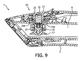
上述の実施態様において、ホルダ19の周壁23は、空洞16内のスチームと接触する芳香収容要素21の表面積を増大させるように構成される突出構造29を含む。これは芳香が空洞16内のスチームに付与される速度を増大させる。しかしながら、突出構造29は省略されてよいことが認識されるべきである。(図9に示す)1つの代替的な実施態様において、ホルダ19の周壁23は、周壁23の厚さを通じて延びる複数の孔23Aを含む。従って、孔23Aに近接する芳香収容要素21の部分は、空洞16内のスチームに晒されて、スチームと接触する芳香収容要素21の表面積を増大させる。他の代替的な実施態様(図示せず)において、周壁は1つの孔を含む。
In the embodiment described above, the
上述の実施態様において、バルブプランジャ18は、バルブ部材14が(図5に示すような)開放位置にあるときにスチームがスチーム通路8と空洞16との間を流れるのを可能にする中空構造を含む。(図10に示す)代替的な実施態様において、内側環13のリップ13Bは、バルブ部材14が開放位置にあるときにスチームがスチーム通路8と空洞16との間を流れるのを可能にする複数の孔13Dを含む。他の代替的な実施態様(図示せず)において、内側環は1つの孔を含む。更に他の実施態様(図示せず)では、間隙がバルブ部材と内側環のリップとの間に設けられることで、バルブ部材が開放位置にあるときに、スチームは前記間隙を通じて流れ得る。
In the embodiment described above, the
上述の実施態様において、外側環及び内側環12,13は別個のコンポーネントであるが、代替的な実施態様(図示せず)において、外側環及び内側環は一体的に形成される。1つの実施態様において、外側環及び/又は内側環は衣類スチーミングデバイスのハウジングと一体的に形成される。
In the embodiment described above, the outer and
上述の実施態様において、本体3は、互いに取り付けられ且つスチームノズル4に取り付けられてハウジング2を形成する、第1及び第2の部分3A,3Bを含むが、代替的な実施態様(図示せず)において、本体の第1及び第2の部分及び/又はスチームノズルは一体的に形成される。
In the embodiment described above, the body 3 includes first and
上述の実施態様において、ハウジング2の開口2Aはスチームノズル4の孔であるが、代替的な実施態様(図示せず)において、ハウジングの開口は本体の孔である。
In the embodiment described above, the
上述の実施態様において、空洞16は、芳香カートリッジ10がハウジング2内に受け入れられて芳香をスチームに付与するよう、ハウジング2のスチームノズル4内に延びる。しかしながら、代替的な実施態様(図示せず)において、空洞16は、代わりに、芳香カートリッジ10が本体3内に受け入れられて芳香をスチームに付与するよう、本体3内に延びる。代替的に、スチームホースの部分がハウジングを含んでよく、ハウジングは貫通して延びるスチーム通路を備えてよい。ハウジングは空洞を有し、芳香カートリッジは空洞内に受け入れられて、スチームホースを通じて流れるスチームに芳香を付与する。更に、他の実施態様(図示せず)において、スチーミングデバイスは、スチーム生成器を収容するベースユニットを含み、スチームホースは、ベースユニットを衣類スチーミングデバイス内のスチーム通路と流体的に連通させる。空洞は、芳香がスチーム生成器内のスチームに付与されるよう、ベースユニット内に延びる。
In the embodiment described above, the
上述の実施態様において、保持部材15は、つる巻バネ15を含むが、代替的な実施態様(図示せず)において、衣類スチーミングデバイスは、異なる種類の保持部材を含む。例えば、保持部材は、代わりに、内側環のリップとバルブプランジャのベースとの間で圧縮されてバルブ部材を閉塞位置に付勢する弾性材料の部分又は異なる種類のバネを含んでよい。1つの代替的な実施態様(図示せず)において、保持部材は、バルブ部材が開放位置に移動させられるときに保持部材が張力下にあるよう、内側環のリップとバルブヘッドのベースとの間に配置される。
In the embodiment described above, the retaining
上述の実施態様において、衣類スチーミングデバイス1はスチーマヘッド1であるが、他の種類の衣類スチーミングデバイスが本発明の範囲内に入ることが意図されることが認識されるべきである。例えば、代替的な実施態様(図示せず)において、衣類スチーミングデバイスは、スチームアイロンである。
In the above-described embodiments, the garment
上述の実施態様は例示的であるに過ぎず、本発明の技術アプローチを限定することを意図しない。本発明は好適な実施態様を参照して詳細に記載されているが、当業者は、本発明の請求項の保護範囲内にも入る本発明の技術アプローチの精神及び範囲から逸脱せずに、本発明の技術アプローチを変更し或いは均等に置換し得ることを理解するであろう。請求項において、「含む」という用語は他の要素又はステップを排除せず、単数形の表現は複数を排除しない。請求項中の如何なる参照符号も範囲を限定するものと解釈されてならない。 The above-described embodiments are merely exemplary and are not intended to limit the technical approach of the present invention. Although the present invention has been described in detail with reference to preferred embodiments, those skilled in the art will recognize that the spirit and scope of the technical approach of the present invention may also fall within the protection scope of the claims of the present invention. It will be understood that the technical approach of the present invention may be altered or evenly replaced. In the claims, the term “comprising” does not exclude other elements or steps, and the singular expression does not exclude the plurality. Any reference signs in the claims should not be construed as limiting the scope.
Claims (15)
スチームの通過のために前記ハウジング内に配置されるスチーム通路と、
該スチーム通路内に延びる空洞と、
該空洞内に取り外し可能に配置される芳香カートリッジと、
前記空洞と前記スチーム通路との間に配置されるバルブアセンブリとを含み、
該バルブアセンブリは、前記芳香カートリッジが前記空洞内に配置されていないときに、前記スチーム通路に対して前記空洞を閉じて、スチームが前記スチーム通路と前記空洞との間を相互作用的に流れるのを妨げるように構成され、
前記バルブアセンブリ及び前記芳香カートリッジは、前記芳香カートリッジが前記空洞内に配置されているときに、前記芳香カートリッジに前記バルブアセンブリを付勢させて、前記スチーム通路に対して前記空洞を開いて、スチームが前記スチーム通路と前記空洞との間を相互作用的に流れるのを可能にするよう協働するように構成される、
衣類スチーミングデバイス。 A housing;
A steam passage disposed within the housing for passage of steam;
A cavity extending into the steam passage ;
An aroma cartridge removably disposed within the cavity;
A valve assembly disposed between the cavity and the steam passage;
The valve assembly closes the cavity with respect to the steam passage when the aroma cartridge is not disposed within the cavity, so that steam flows interactively between the steam passage and the cavity. Configured to prevent
The valve assembly and the scent cartridge are configured to cause the scent cartridge to bias the valve assembly when the scent cartridge is disposed in the cavity, thereby opening the cavity with respect to the steam passage, Configured to cooperate to allow interactive flow between the steam passage and the cavity;
Clothing steaming device.
Applications Claiming Priority (3)
| Application Number | Priority Date | Filing Date | Title |
|---|---|---|---|
| EP15168317.4 | 2015-05-20 | ||
| EP15168317 | 2015-05-20 | ||
| PCT/EP2016/061241 WO2016184957A1 (en) | 2015-05-20 | 2016-05-19 | A garment steaming device with valve assembly for a fragrance cartridge |
Publications (2)
| Publication Number | Publication Date |
|---|---|
| JP2017534369A JP2017534369A (en) | 2017-11-24 |
| JP6333476B2 true JP6333476B2 (en) | 2018-05-30 |
Family
ID=53181172
Family Applications (1)
| Application Number | Title | Priority Date | Filing Date |
|---|---|---|---|
| JP2017519287A Active JP6333476B2 (en) | 2015-05-20 | 2016-05-19 | Clothing steaming device with valve assembly for fragrance cartridge |
Country Status (10)
| Country | Link |
|---|---|
| US (1) | US10407819B2 (en) |
| EP (1) | EP3177764B1 (en) |
| JP (1) | JP6333476B2 (en) |
| KR (1) | KR101788587B1 (en) |
| CN (1) | CN106715783B (en) |
| ES (1) | ES2669621T3 (en) |
| PL (1) | PL3177764T3 (en) |
| RU (1) | RU2698840C2 (en) |
| TR (1) | TR201808236T4 (en) |
| WO (1) | WO2016184957A1 (en) |
Families Citing this family (6)
| Publication number | Priority date | Publication date | Assignee | Title |
|---|---|---|---|---|
| DE102018222295A1 (en) * | 2018-12-19 | 2020-06-25 | Henkel Ag & Co. Kgaa | Functional element for a hand-held steam generator for the treatment of garments and hand-held steam generator |
| KR20210107775A (en) * | 2018-12-21 | 2021-09-01 | 요트. 바그너 게엠베하 | A storage medium for an electrodynamic atomizer and a fluid tank having a valve system and a method of operation of the atomizer and atomizer |
| USD940412S1 (en) * | 2020-01-08 | 2022-01-04 | Lg Electronics Inc. | Garment steamer |
| USD955072S1 (en) * | 2020-02-07 | 2022-06-14 | Steamery Ab | Steam iron |
| USD946837S1 (en) * | 2020-08-04 | 2022-03-22 | Fine Dragon Technology Limited | Steamer |
| FR3115299B1 (en) * | 2020-10-16 | 2023-12-22 | Seb Sa | PORTABLE DECREASING DEVICE COMPRISING AN ADDITIVE DIFFUSION DEVICE |
Family Cites Families (13)
| Publication number | Priority date | Publication date | Assignee | Title |
|---|---|---|---|---|
| US3263350A (en) * | 1958-12-18 | 1966-08-02 | Abraham Carlos Salomon | Electric steam iron |
| FR2663052B1 (en) * | 1990-06-11 | 1992-09-04 | Seb Sa | ELECTRIC IRON WITH DEMINERALIZING CARTRIDGE AND IMPROVED WATER TANK. |
| DE29601699U1 (en) * | 1996-02-01 | 1997-06-05 | Aeg Hausgeraete Gmbh | Electric steam iron |
| DE19834605A1 (en) * | 1998-07-31 | 2000-02-03 | Braun Gmbh | Steamer |
| FR2804137B1 (en) * | 2000-01-20 | 2003-07-04 | Moulinex Sa | IRON COMPRISING A PUMP MIXED WITH WATER AND TEXTILE ADJUVANT |
| SG86370A1 (en) * | 2000-02-01 | 2002-02-19 | Koninkl Philips Electronics Nv | Electric iron |
| SG86412A1 (en) * | 2000-06-30 | 2002-02-19 | Koninkl Philips Electronics Nv | Electric iron with exchangeable reservoir |
| WO2004018936A1 (en) * | 2002-08-26 | 2004-03-04 | Koninklijke Philips Electronics N.V. | Electric steaming device |
| JP4966010B2 (en) * | 2003-05-16 | 2012-07-04 | コーニンクレッカ フィリップス エレクトロニクス エヌ ヴィ | Iron with cartridge |
| FR2868442B1 (en) * | 2004-04-01 | 2006-05-26 | Seb Sa | IRON CONTAINING AN ADDITIVE RESERVOIR |
| JP2008043651A (en) * | 2006-08-21 | 2008-02-28 | Mitsubishi Electric Corp | Washing machine |
| CN101622394B (en) * | 2007-02-28 | 2011-06-29 | 皇家飞利浦电子股份有限公司 | Steaming system |
| TWM499525U (en) * | 2014-09-25 | 2015-04-21 | Jin-hui WANG | Negative ion lighting device |
-
2016
- 2016-05-19 PL PL16725807T patent/PL3177764T3/en unknown
- 2016-05-19 CN CN201680002872.9A patent/CN106715783B/en active Active
- 2016-05-19 EP EP16725807.8A patent/EP3177764B1/en active Active
- 2016-05-19 US US15/508,517 patent/US10407819B2/en active Active
- 2016-05-19 JP JP2017519287A patent/JP6333476B2/en active Active
- 2016-05-19 ES ES16725807.8T patent/ES2669621T3/en active Active
- 2016-05-19 KR KR1020177007985A patent/KR101788587B1/en active IP Right Grant
- 2016-05-19 TR TR2018/08236T patent/TR201808236T4/en unknown
- 2016-05-19 RU RU2017113268A patent/RU2698840C2/en active
- 2016-05-19 WO PCT/EP2016/061241 patent/WO2016184957A1/en active Application Filing
Also Published As
| Publication number | Publication date |
|---|---|
| WO2016184957A1 (en) | 2016-11-24 |
| KR101788587B1 (en) | 2017-10-20 |
| US10407819B2 (en) | 2019-09-10 |
| US20180073190A1 (en) | 2018-03-15 |
| CN106715783B (en) | 2019-05-03 |
| KR20170040361A (en) | 2017-04-12 |
| RU2017113268A3 (en) | 2019-07-17 |
| TR201808236T4 (en) | 2018-07-23 |
| CN106715783A (en) | 2017-05-24 |
| RU2017113268A (en) | 2018-10-19 |
| ES2669621T3 (en) | 2018-05-28 |
| PL3177764T3 (en) | 2018-08-31 |
| EP3177764B1 (en) | 2018-03-21 |
| JP2017534369A (en) | 2017-11-24 |
| RU2698840C2 (en) | 2019-08-30 |
| EP3177764A1 (en) | 2017-06-14 |
Similar Documents
| Publication | Publication Date | Title |
|---|---|---|
| JP6333476B2 (en) | Clothing steaming device with valve assembly for fragrance cartridge | |
| AU2001296321B2 (en) | An improved system for fitting a container to a distribution device | |
| US7743443B2 (en) | Liquid applicator and absorbent scrubbing means | |
| EP3252205B1 (en) | Laundry treatment apparatus | |
| JP6151575B2 (en) | Nozzle for aerosol container and discharge tool for aerosol container | |
| US8458853B2 (en) | Steam cleaner including a quick release coupling for a cleaning tool | |
| JP2017516580A (en) | Steam iron for receiving fragrance cartridge | |
| JP6435182B2 (en) | Quantitative injection mechanism of aerosol container | |
| TWI619449B (en) | Atomizer | |
| KR20130104112A (en) | Steam brush apparatus for cleaning shoes | |
| JP3169921U (en) | Portable spray equipment | |
| JP3081961B2 (en) | Portable local washer | |
| JP4162576B2 (en) | Attachment for mixing | |
| KR101908580B1 (en) | Portable clothing strain remover | |
| KR101605043B1 (en) | Spraying apparatus and spryaing can having the same | |
| JP2008007167A (en) | Hood for sprayer, and sprayer | |
| JP4756779B2 (en) | Attachment for mixing | |
| JP6892059B2 (en) | Attachment mounting structure for aerosol or pump products and aerosol and pump products with this attachment mounting structure | |
| JP2023142808A (en) | Shower head installation adapter | |
| CN115110289A (en) | Clothes nursing machine | |
| JPH0768200A (en) | Spray gun and coating storing container attached thereto | |
| JP2019122714A (en) | Steam iron | |
| JP2016159970A (en) | Spray device and liquid container | |
| KR20100084906A (en) | Clothes dryer having fragrance supplying device with pressure hole | |
| JP2015096423A (en) | Piston cylinder device for spray and spray using the same |
Legal Events
| Date | Code | Title | Description |
|---|---|---|---|
| A975 | Report on accelerated examination |
Free format text: JAPANESE INTERMEDIATE CODE: A971005 Effective date: 20170824 |
|
| A131 | Notification of reasons for refusal |
Free format text: JAPANESE INTERMEDIATE CODE: A131 Effective date: 20171107 |
|
| TRDD | Decision of grant or rejection written | ||
| A01 | Written decision to grant a patent or to grant a registration (utility model) |
Free format text: JAPANESE INTERMEDIATE CODE: A01 Effective date: 20180327 |
|
| A61 | First payment of annual fees (during grant procedure) |
Free format text: JAPANESE INTERMEDIATE CODE: A61 Effective date: 20180424 |
|
| R150 | Certificate of patent or registration of utility model |
Ref document number: 6333476 Country of ref document: JP Free format text: JAPANESE INTERMEDIATE CODE: R150 |
|
| R250 | Receipt of annual fees |
Free format text: JAPANESE INTERMEDIATE CODE: R250 |
|
| R250 | Receipt of annual fees |
Free format text: JAPANESE INTERMEDIATE CODE: R250 |
|
| R250 | Receipt of annual fees |
Free format text: JAPANESE INTERMEDIATE CODE: R250 |
|
| S111 | Request for change of ownership or part of ownership |
Free format text: JAPANESE INTERMEDIATE CODE: R313113 |
|
| R350 | Written notification of registration of transfer |
Free format text: JAPANESE INTERMEDIATE CODE: R350 |