JP6331663B2 - Inkjet device - Google Patents
Inkjet device Download PDFInfo
- Publication number
- JP6331663B2 JP6331663B2 JP2014096129A JP2014096129A JP6331663B2 JP 6331663 B2 JP6331663 B2 JP 6331663B2 JP 2014096129 A JP2014096129 A JP 2014096129A JP 2014096129 A JP2014096129 A JP 2014096129A JP 6331663 B2 JP6331663 B2 JP 6331663B2
- Authority
- JP
- Japan
- Prior art keywords
- stage
- nozzle head
- alignment mark
- ink
- axis
- Prior art date
- Legal status (The legal status is an assumption and is not a legal conclusion. Google has not performed a legal analysis and makes no representation as to the accuracy of the status listed.)
- Active
Links
Images
Landscapes
- Coating Apparatus (AREA)
- Ink Jet (AREA)
Description
本発明は、インクジェット装置に関し、特にディスプレイをはじめとする高精度な積層構造を有する電子デバイスを製造するためのインクジェット装置に関する。 The present invention relates to an ink jet equipment, and more particularly to an ink jet apparatus for producing an electronic device having a high-precision laminated structure including a display.
ディスプレイや半導体集積回路では、基板上に複数層の電子材料膜をパターニングし、積層することで製造されている。従来ではフォトリソグラフィ技術によって高精細なパターニングを行っているが、近年、このプロセスを印刷プロセスにて実現しようとするプリンテッドエレクトロニクス分野が注目されている。 A display or a semiconductor integrated circuit is manufactured by patterning and laminating a plurality of layers of electronic material films on a substrate. Conventionally, high-definition patterning has been performed by photolithography, but recently, the printed electronics field in which this process is to be realized by a printing process has attracted attention.
プリンテッドエレクトロニクス分野で用いる印刷プロセスとして、スクリーン印刷、グラビア印刷、マイクロコンタクト印刷など多くの方法が検討、開発されているがインクジェット法もその一つである。 As a printing process used in the printed electronics field, many methods such as screen printing, gravure printing, and microcontact printing have been studied and developed, and the inkjet method is one of them.
インクジェット技術は、画像記録装置向けに広く利用されており、既に確立された技術分野である。しかし、プリンテッドエレクトロニクスとして用いるインクジェット装置の仕様として従来技術では対応できない課題も多い。
その一つにパターン形成の位置ずれがある。既に形成されてある下地のパターンに対し、上に積層するパターンが位置ずれを起こしてしまうと、設計通りの電子デバイスの特性が得られない。プリンテッドエレクトロニクスで電子デバイスを製造するためには、サブミクロンから10μm程度の位置精度が要求される。そのために、インクジェット装置に搭載するノズルヘッドの位置決めは非常に重要である。
Inkjet technology is widely used for image recording apparatuses and is an established technical field. However, there are many problems that cannot be dealt with by the prior art as specifications of the ink jet apparatus used as printed electronics.
One of them is misalignment of pattern formation. If the pattern to be stacked on the base pattern already formed is displaced, the characteristics of the electronic device as designed cannot be obtained. In order to manufacture an electronic device by printed electronics, a positional accuracy of about submicron to 10 μm is required. Therefore, the positioning of the nozzle head mounted on the ink jet apparatus is very important.
例えば、アライメントカメラとノズルヘッドの基準位置を予め把握しておき、アライメントカメラで描画対象物に事前に形成してあるアライメントマークを検出した際の位置から前記基準位置との変位量を算出する。そして、算出した変位量からノズルヘッドと描画対象物の位置関係を調整する塗布装置及び塗布方法が知られている(例えば、特許文献1参照)。 For example, the reference position of the alignment camera and the nozzle head is grasped in advance, and the amount of displacement from the reference position is calculated from the position when the alignment mark formed in advance on the drawing object is detected by the alignment camera. And the coating device and the coating method which adjust the positional relationship of a nozzle head and a drawing target object from the calculated displacement amount are known (for example, refer patent document 1).
しかしながら、特許文献1に代表される技術では、以下の問題に対処できない。即ち、ノズル形状の僅かな違いのメニスカス挙動による吐出曲がりの問題に対処できない。また、描画対象物に対する設置誤差である機械的なノズルの傾きに対しては言及しておらず、やはり吐出曲がりの問題が懸念される。
However, the technique represented by
また、ノズルヘッドとアライメントマークが形成されたプレートを用意し、プレート上のアライメントマークを基準としてノズルヘッドのアライメントを行う方法が知られている(例えば、特許文献2参照)。 In addition, a method is known in which a plate on which a nozzle head and an alignment mark are formed is prepared, and the nozzle head is aligned based on the alignment mark on the plate (for example, see Patent Document 2).
しかしながら、特許文献2に代表される技術では、位置合わせに使用するレンズからの距離が異なるノズルヘッドとアライメントマークを同時に観察するために、二重焦点レンズを用意しなければならず、カメラユニットだけでもコストが多くかかってしまう。また、ノズルヘッドの仕様の種類分のアライメントマークが形成されたプレートを用意しなければならず、ノズル間隔やノズル本数、設置するノズルヘッドの数が容易に変更できない問題がある。
However, in the technique represented by
したがって、プリンテッドエレクトロニクスに用いるインクジェット装置において、ノズルヘッドの高精度な位置決めを容易に行うことが可能な装置の提供が求められているのが現状である。 Accordingly, the present situation is that there is a demand for an apparatus capable of easily positioning a nozzle head with high accuracy in an inkjet apparatus used in printed electronics.
本発明は、上述した事情に鑑みてなされたものであり、従来における前記諸問題を解決し、以下の目的を達成することを課題とする。即ち、ノズルヘッドの高精度な位置決めを容易に行うことができ、描画する積層パターンの位置ずれを抑えることができる、インクジェット装置を提供することを目的としている。 This invention is made | formed in view of the situation mentioned above, and makes it a subject to solve the said various problems in the past and to achieve the following objectives. That is, an object of the present invention is to provide an ink jet apparatus that can easily position a nozzle head with high accuracy and can suppress a positional deviation of a layered pattern to be drawn.
上記目的を達成するために、本発明は、インクの吐出機構を有するノズルヘッドと、対象物を載置するテーブルを任意の位置に移動するステージと、前記吐出機構から吐出されるインクによって形成されたアライメントマークを撮像する撮像手段と、前記対象物に前記アライメントマークを形成する際の前記ステージの第1の位置情報と、前記アライメントマークを前記撮像手段で撮像する際の前記ステージの第2の位置情報とを記憶する記憶手段と、前記記憶手段に記憶された前記第1の位置情報と、前記第2の位置情報とから、前記ノズルヘッドと前記撮像手段との相対位置を算出する算出手段と、前記算出手段により算出された結果に基づいて、前記ステージを移動する制御手段と、を備え、前記撮像手段は、前記アライメントマークの形成位置に位置合わせするための位置合わせ手段を有し、前記第2の位置情報を取得するインクジェット装置である。 In order to achieve the above object, the present invention is formed by a nozzle head having an ink ejection mechanism, a stage for moving a table on which an object is placed to an arbitrary position, and ink ejected from the ejection mechanism. Imaging means for imaging the alignment mark, first position information of the stage when forming the alignment mark on the object, and second stage of the stage when imaging the alignment mark with the imaging means Storage means for storing position information, and calculation means for calculating a relative position between the nozzle head and the imaging means from the first position information and the second position information stored in the storage means. If, based on the result calculated by the calculating means, and control means for moving the stage, the image pickup means, the alignment mark Having alignment means for aligning the forming position, an ink jet apparatus for acquiring the second position information.
本発明によれば、上記構成により、従来における前記諸問題を解決することができ、描画対象物に対してノズルヘッドを正確且つ容易に位置決め可能とする、インクジェット装置を提供することができる。 According to the present invention, the above-described configuration can solve the conventional problems, and can provide an ink jet apparatus that enables the nozzle head to be accurately and easily positioned with respect to the drawing object.
以下、図を参照して実施例を含む本発明の実施の形態(以下、「実施形態」という)を詳細に説明する。各実施形態や実施例等に亘り、同一の機能および形状等を有する構成要素(部材や構成部品)等については、混同の虞がない限り一度説明した後では同一符号を付すことによりその説明を省略する。図および説明の簡明化を図るため、図に表されるべき構成要素であっても、その図において特別に説明する必要がない構成要素は適宜断わりなく省略することがある。 Hereinafter, embodiments of the present invention including examples will be described in detail with reference to the drawings. In the embodiments and examples, components (members and components) having the same functions and shapes are described once by giving the same reference numerals after being described once unless there is a possibility of confusion. Omitted. In order to simplify the drawings and the description, even if the components are to be represented in the drawings, the components that do not need to be specifically described in the drawings may be omitted as appropriate.
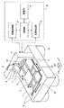
図1〜図5を参照して、本発明の一実施の形態について説明する。先ず、図1を参照して、本発明の一実施の形態に係る、電子デバイス製造のためのインクジェット装置について説明する。図1は、本発明の一実施の形態に係るインクジェット装置の斜視図である。
図1に示すインクジェット装置は、定盤1、XYZθステージ2、吸着テーブル3、ガントリ4、ガントリZステージ5、ノズルヘッドユニット6、カメラユニット7、X軸ガイドレール8、Y軸ガイドレール9、除振台10により主に構成されている。このインクジェット装置を構成する上記各部材や各部品の寸法については、特に説明しないが後述する位置精度及び各機能を満足するよう適切に設定されることは無論である。
尚、図1において、Z軸は鉛直方向を、θ軸は鉛直方向に対する回転方向を、それぞれ示している。また、X軸及びY軸は互いに直交し、尚且つ、Z軸に対し直交するよう配置された3次元直交座標系となっている。
An embodiment of the present invention will be described with reference to FIGS. First, an ink jet apparatus for manufacturing an electronic device according to an embodiment of the present invention will be described with reference to FIG. FIG. 1 is a perspective view of an ink jet apparatus according to an embodiment of the present invention.
1 includes a
In FIG. 1, the Z axis indicates the vertical direction, and the θ axis indicates the rotational direction with respect to the vertical direction. Further, the X axis and the Y axis are orthogonal to each other, and are a three-dimensional orthogonal coordinate system arranged so as to be orthogonal to the Z axis.
定盤1には、XYZθステージ2を往復移動可能に取り付けるためのX軸ガイドレール8及びY軸ガイドレール9と、ガントリZステージ5を鉛直方向に往復移動可能に取り付けるためのガントリ4と、周囲の振動が伝わらないように除振台10と、が備わっている。
On the
XYZθステージ2のX軸方向には、定盤1に固定されたX軸ガイドレール8に沿って往復移動可能なX軸直線移動ステージ2Xが備わっている。X軸直線移動ステージ2Xは、例えば、サーボ機構を備えたリニアモータ等の制御可能な駆動手段と、X軸ガイドレール8に沿って移動案内するリニアエアガイドのような案内手段とから構成された移動手段を介して、X軸方向に往復移動可能に構成されている。X軸直線移動ステージ2Xは、X軸ガイドレール8に平行に備わったリニアスケール、リニアエンコーダ等の図示しないセンサ及び上記駆動手段を介して、指令した制御量に基づいて吸着テーブル3が所定のX軸座標に位置するように制御されるようになっている。この場合のX軸の位置精度としては、高精細な電子デバイスを製造するためにはサブミクロンから10μmまでの精度が好ましい。
尚、X軸直線移動ステージ2Xの移動手段は、上記したものに限らず、上記位置精度が確保される限り、サーボモータ、ステップモータ等の制御可能な駆動手段と、ラックアンドピニオン等の案内手段とから構成されたものであってもよい。
In the X-axis direction of the
The moving means of the X-axis linear moving
XYZθステージ2のY軸方向には、定盤1に固定されたY軸ガイドレール9に沿って往復移動可能なY軸直線移動ステージ2Yが備わっている。Y軸直線移動ステージ2Yは、例えば、サーボ機構を備えたリニアモータ等の制御可能な駆動手段と、Y軸ガイドレール9に沿って移動案内するリニアエアガイドのような案内手段とから構成された移動手段を介して、Y軸方向に往復移動可能に構成されている。Y軸直線移動ステージ2Yは、Y軸ガイドレール9に平行に備わったリニアスケール、リニアエンコーダ等の図示しないセンサ及び上記駆動手段を介して、指令した制御量に基づいて吸着テーブル3が所定のY軸座標に位置するように制御されるようになっている。この場合のY軸の位置精度としては、高精細な電子デバイスを製造するためにはサブミクロンから10μmまでの精度が好ましい。
尚、Y軸直線移動ステージ2Yの移動手段は、上記したものに限らず、上記位置精度が確保される限り、サーボモータ、ステップモータ等の制御可能な駆動手段と、ラックアンドピニオン等の案内手段と、から構成されたものであってもよい。
In the Y-axis direction of the
The moving means of the Y-axis linear moving
XYZθステージ2のZ軸方向には、XYZθステージ2と吸着テーブル3との間に、図1の鉛直方向であるZ軸方向に沿って往復移動可能なZ軸直線移動ステージ(図示せず)が備わっている。このZ軸直線移動ステージは、例えば、サーボ機構を備えたリニアモータ等の制御可能な駆動手段と、Z軸方向に沿って移動案内するリニアエアガイドのような案内手段とから構成された移動手段を介して、Z軸方向に往復移動可能に構成されている。また、上記Z軸直線移動ステージは、Z軸方向に平行に備わったリニアスケール、リニアエンコーダ等の図示しないセンサ及び上記駆動手段を介して、指令した制御量に基づいて吸着テーブル3が所定のZ軸座標に位置するように制御されるようになっている。
ここで言うZ軸は、描画対象物とノズルヘッドユニット6との間のギャップを制御するためのものであり、ガントリZステージ5のZ軸でそのギャップを制御できるならば必ずしも必要ではない。
尚、上記Z軸直線移動ステージの移動手段は、上記したものに限らず、上記機能が確保される限り、サーボモータ、ステップモータ等の制御可能な駆動手段と、ラックアンドピニオン等の案内手段と、から構成されたものであってもよい。
In the Z-axis direction of the
The Z axis here is for controlling the gap between the object to be drawn and the
The moving means of the Z-axis linear moving stage is not limited to the above, but as long as the above functions are ensured, controllable driving means such as a servo motor and step motor, and guide means such as a rack and pinion , May be configured.
XYZθステージ2のθ軸方向には、XYZθステージ2と吸着テーブル3との間に、回動(正逆方向に円運動することを意味する)可能な回転ステージ(図示せず)が備わっている。この回転ステージは、例えば、サーボ機構を備えたリニアモータ等の制御可能な駆動手段と、所定の回転軸方向に回動可能に案内するころがりガイドのような案内手段とから構成された移動手段を介して、所定の回転軸方向に回動可能に構成されている。また、上記回転ステージは、XYZθステージ2と吸着テーブル3との間に備わったリニアスケール、リニアエンコーダ等の図示しないセンサ及び上記駆動手段を介して、指令した制御量に基づいて吸着テーブル3が所定のθ位置に制御されるようになっている。この場合のθ軸は、描画対象物のアライメント操作に用いることを主としている。
尚、上記回転ステージの移動手段は、上記したものに限らず、所定の位置精度が確保される限り、サーボモータ、ステップモータ等の制御可能な駆動手段と、適宜の案内手段と、から構成されたものであってもよい。
In the θ-axis direction of the
The rotating stage moving means is not limited to the above-described one, and includes a controllable driving means such as a servo motor and a step motor, and appropriate guiding means as long as a predetermined positional accuracy is ensured. It may be.
吸着テーブル3は、XYZθステージ2に固定されており、描画対象物を吸着によって固定して載置するためのテーブルである。この場合の吸着は、例えば吸着テーブル3と描画対象物の間を減圧ないしは真空に近い状態にすることによって描画対象物を固定することが可能に構成されている。即ち、吸着テーブル3表面には、減圧ないしは真空状態にするための複数の空気孔(図示せず)が設けられていて、この複数の空気孔は、これらに連通するパイプ(図示せず)を通じて吸引手段としての図示しない真空ポンプ等に連通・接続されている。
The suction table 3 is fixed to the
上記したとおり、XYZθステージ2のX軸直線移動ステージ2X、Y軸直線移動ステージ2Y、上記Z軸直線移動ステージ及び上記各回転ステージは、上記各移動手段を介して以下のように構成されていた。即ち、上記各ステージは、上記各移動手段を介して吸着テーブル3を任意の位置に移動調整することが可能で、且つ任意の位置を検出することが可能に構成されている。
As described above, the X-axis
ガントリ4は、門型構造をなし、XYZθステージ2及び吸着テーブル3を跨ぐように定盤1に固定されている。ガントリ4には、ガントリZステージ5がZ軸方向に往復移動可能に取り付けられている。ガントリZステージ5には、ノズルヘッドユニット6と、カメラユニット7とが取り付け・固定されている。
The
ガントリZステージ5は、例えば、サーボ機構を備えたリニアモータ等の制御可能な駆動手段と、Z軸方向に沿って移動案内するころがりガイドのような案内手段とから構成された移動手段を介して、Z軸方向に往復移動可能に構成されている。ガントリZステージ5は、上記案内手段に備わったリニアスケール、リニアエンコーダ等のセンサ及び上記駆動手段を介して、指令した制御量に基づいてノズルヘッドユニット6及びカメラユニット7が所定のZ軸座標に位置するように制御されるようになっている。
ここで言うZ軸は、描画対象物とノズルヘッドユニット6との間のギャップを制御するためのものであり、XYZθステージ2のZ軸でそのギャップを制御できるならば必ずしも必要ではない。またこの場合、カメラユニット7は、必ずしもガントリZステージ5に取り付ける必要はなく、ガントリ4に直接固定、又は別途固定するための器材を用意してもよい。
尚、ガントリZステージ5の移動手段は、上記したものに限らず、上記機能を満足する限り、サーボモータ、ステップモータ等の制御可能な駆動手段と、ラックアンドピニオン等の案内手段とから構成されたものであってもよい。
The
The Z axis here is for controlling the gap between the object to be drawn and the
The moving means of the
ノズルヘッドユニット6は、それぞれ図示しない、インク吐出が可能な複数のN本(N≧1)のノズルヘッドと、電子デバイスを製造するための材料インクと、その材料インクを吐出するための吐出機構が備わっている。ここで言う材料インクとしては、電極材料、半導体材料、発光材料、バンク材料、レジスト材料等の積層構造を有する電子デバイス製造に必要な材料を含むインクが挙げられる。
ノズルヘッドユニット6に備わったノズルヘッドの吐出機構は、後述する図4に示す描画対象物30に形成するアライメントマーク32を形成するマーク形成手段として機能する。上記したとおり、アライメントマーク32は、ノズルヘッドに充填されたインクとしての、電極材料、半導体材料、発光材料、バンク材料及びレジスト材料の何れかによって形成される。
また、ここで言うノズルヘッドは、製造したい電子デバイスを構成する材料インクの違い、ノズルヘッドの解像度の違い、ノズルヘッドのメンテナンスに対応できるようにノズルヘッドユニット6に対して着脱可能であり、付け替えができるように構成されている。
The
The nozzle head ejection mechanism provided in the
The nozzle head here is detachable from the
カメラユニット7には、後述する図4に示す描画対象物30の印刷面に対してZ軸方向に沿って垂直に、及びXYZθステージ2の移動範囲内で描画対象物30を撮像・観察できるように構成された撮像手段としてのアライメントカメラが備わっている。このアライメントカメラは、上記した特許文献2に用いられる二重焦点レンズのような高価なものでなく、通常のレンズを備えた比較的低価格のものが用いられる。
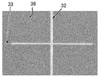
また、カメラユニット7の映像には、後述する図5に示すアライメントマーク32の形成位置を位置合わせするための位置合わせ手段としてのガイドライン33が備わっている。
尚、撮像手段としては、一般的にアライメントカメラに用いるCCDカメラ又は上記機能を発揮する同等の撮像手段でもよい。
The
The video of the
In addition, as an imaging means, the CCD camera generally used for an alignment camera or the equivalent imaging means which exhibits the said function may be sufficient.
図1に示すように、インクジェット装置には、ノズルヘッドの位置決めを行うインクジェット装置の動作を制御するための制御装置35を備えている。制御装置35は、制御部11と、後述する算出手段及び制御手段として機能する各軸制御部12と、位置検出部13と、後述する第1及び第2の記憶手段として機能する記憶部14とを有して構成されている。
As shown in FIG. 1, the ink jet apparatus includes a
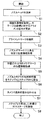
図2を参照して、本発明に係るインクジェット装置に組み込んだ主なシーケンスの流れを説明する。尚、図2のフローチャートにおいては、ノズルヘッドを単に「ノズル」と、アライメントマークのことを単に「マーク」と、アライメントカメラのことを単に「カメラ」と、それぞれ記載している。
先ず、インク吐出が可能なノズルヘッドを、図1のノズルヘッドユニット6に設置する(ステップS1)。次いで、描画対象物を図1の吸着テーブル3に設置し、上記各ステージの座標位置に対する描画対象物のアライメントを実施する(ステップS2)。即ち、図1のXYZθステージ2上の吸着テーブル3に描画対象物を載置したときに、描画対象物とXYZθステージの座標との関係付けを行う。尚、量産工程を考慮すれば、吸着テーブル3に描画対象物を載置するような動作も、例えばテーチングされたロボットで全自動的に実施することも可能である。
With reference to FIG. 2, the flow of the main sequence incorporated in the inkjet apparatus according to the present invention will be described. In the flowchart of FIG. 2, the nozzle head is simply described as “nozzle”, the alignment mark as simply “mark”, and the alignment camera as simply “camera”.
First, a nozzle head capable of ejecting ink is installed in the
次いで、本発明に特有の工程でもある、描画対象物に対し、新たにアライメントマークを描画する(ステップS3、マーク形成ステップ)。具体的には、後述する図4に示すように、ノズルヘッドユニット6に備わったノズルヘッドのインクの吐出機構によって、描画対象物30にアライメントマーク32を描画し形成する。
Next, an alignment mark is newly drawn on the drawing target, which is a process unique to the present invention (step S3, mark forming step). Specifically, as shown in FIG. 4 to be described later, an
次いで、ノズルヘッド全体を位置決めするために基準となるノズルが、ステップS3で形成したアライメントマークの所定の位置上にある状態でステージ位置情報を取得し記憶する(ステップS4、第1の記憶ステップ)。ここで言う「所定の位置上」というのは目測ではなく、ステージ位置情報を基にした数値上で位置合わせを行うことを意味する。 Next, the stage position information is acquired and stored in a state where the reference nozzle for positioning the entire nozzle head is on the predetermined position of the alignment mark formed in step S3 (step S4, first storage step). . Here, “on a predetermined position” does not mean eye measurement, but means that alignment is performed on a numerical value based on stage position information.
ステップS5に進み、アライメントカメラのガイドラインと、ステップS4で位置合わせしたアライメントマークの同位置を合わせたときのステージ位置情報を取得し記憶する(第2の記憶ステップ)。次いで、ノズルヘッド全体を位置決めするために基準となるノズルとアライメントカメラの相対位置(相対座標値)をステップS4とステップS5のステージ位置情報から算出する(ステップS6、算出ステップ)。 Proceeding to step S5, the stage position information when the alignment camera guideline and the alignment mark aligned in step S4 are aligned is acquired and stored (second storage step). Next, a relative position (relative coordinate value) between the reference nozzle and the alignment camera for positioning the entire nozzle head is calculated from the stage position information in step S4 and step S5 (step S6, calculation step).
次いで、描画を開始したい位置、例えば描画対象物の積層された下地のパターンをアライメントカメラのガイドラインに位置を合わせる(ステップS7)。次いで、ステップS8に進み、ステップS6で算出したノズルヘッド全体を位置決めするために基準となるノズルとアライメントカメラの相対位置の座標分だけステージを動かす(移動ステップ)。これにより、描画対象物に対してノズルヘッドを意図した位置に精度良く位置決めすることができる。
尚、図2に示したステップS1とステップS2の手順は、逆でもよい。
Next, the position at which drawing is to be started, for example, the pattern of the substrate on which the drawing object is stacked is aligned with the alignment camera guideline (step S7). Next, the process proceeds to step S8, and the stage is moved by the coordinate of the relative position between the nozzle serving as the reference and the alignment camera in order to position the entire nozzle head calculated in step S6 (moving step). Thereby, the nozzle head can be accurately positioned at the intended position with respect to the drawing object.
Note that the procedure of step S1 and step S2 shown in FIG. 2 may be reversed.
本発明で提案するインクジェット装置の場合、ノズルヘッドの設置による誤差やノズル固有の曲がりによってインクの着弾が本来想定する着弾基準位置からずれて描画されたとしても、以下のようにステージ情報の取得とすることができる。即ち、そのずれて描画されたアライメントマークをアライメントカメラで位置合わせするので位置ずれを含んだステージ情報の取得となる。その結果、位置ずれを考慮したノズルヘッドの位置決めとなる。 In the case of the ink jet apparatus proposed in the present invention, even if the ink landing is deviated from the originally assumed landing reference position due to an error due to the installation of the nozzle head or a bending specific to the nozzle, acquisition of stage information is performed as follows. can do. That is, since the alignment marks drawn with the shift are aligned by the alignment camera, the stage information including the shift is acquired. As a result, the nozzle head is positioned in consideration of the displacement.
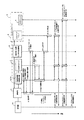
図3を参照して、ノズルヘッドの位置決めを行うインクジェット装置で描画対象物に所定の描画を行うためのシーケンス制御を説明する。図3は、本発明の一実施の形態に係る、電子デバイス製造のためのインクジェット装置の描画対象物に対し所定の描画を行うためのシーケンス制御を説明する図である。
XYZθステージ2及びガントリZステージ5は、ステージ制御コントローラを含む各軸制御部12及び位置検出部13に接続されている。ノズルヘッドユニット6は、インクの吐出機構に備えられた吐出発生装置15に接続され、各軸制御部12及び吐出発生装置15は、制御部11に接続されている。ここで言う、制御部11はパーソナルコンピュータ(PC)に代表されるように、使用者がインタフェース上で簡易的に本発明のインクジェット装置を操作可能にしているものである。また、各軸制御部12は、XYZθステージ2とガントリZステージ5を制御するものであり、各軸制御部12には図1に示した各軸の位置情報・データを取得できる手段が備わっている。
With reference to FIG. 3, sequence control for performing predetermined drawing on an object to be drawn by the ink jet apparatus that positions the nozzle head will be described. FIG. 3 is a diagram illustrating sequence control for performing predetermined drawing on a drawing target of an ink jet apparatus for manufacturing an electronic device according to an embodiment of the present invention.
The
即ち、各軸制御部12は、XYZθステージ2のX軸直線移動ステージ2X、Y軸直線移動ステージ2Y、上記Z軸直線移動ステージ、上記回転ステージ及びガントリZステージ5の上記各リニアモータ及び上記各センサを備えた位置検出部13に接続されている。
位置検出部13は、上記したXYZθステージ2のX軸直線移動ステージ2X、Y軸直線移動ステージ2Y、上記Z軸直線移動ステージ、上記回転ステージ及びガントリZステージ5の上記各リニアエンコーダ・センサである検出手段に接続されている。換言すれば、位置検出部13は、上記各センサである検出手段ないし位置検知手段に接続されている。
That is, each
The
各軸制御部12は、ステージ制御コントローラとして、CPU、I/O(入出力)ポート、PROM等を含むROM、RAM及びタイマ等を備え、それらが信号バスによって接続された構成を有する汎用のマイクロコンピュータを具備して構成することもできる。上記CPUは、制御手段として後述する制御を行うための演算機能及び制御機能を有する。上記ROMには、上記CPUの演算機能及び制御機能を発揮するための、本発明に係るプログラム(例えば図2や図3に示すフローチャート)や、上記CPUの演算機能及び制御機能を発揮するための関係データが予め記憶されている。上記RAMは、例えば電池等の電源でバックアップされ、上記CPUを介して入出力される情報・データを随時記憶し、上記インクジェット装置のメイン電源オフ後も情報・データを記憶保持する。上記タイマは、例えば電池等の電源でバックアップされ、上記インクジェット装置のメイン電源オフ後も計時動作を継続する計時手段として機能する。
尚、各軸制御部12及び制御部11の上記各機能を分割・分担して相互に補完するように構成してもよい。
Each
In addition, you may comprise so that each said function of each axis |
記憶部14は、制御部11を介して、各軸制御部12及び位置検出部13に接続されている。記憶部14は、後述する図4に示す描画対象物30に形成されたアライメントマーク32の形成位置とノズルヘッドユニット6のアライメントカメラを位置合わせした際のXYZθステージ2の位置情報を取得し記憶する第1の記憶手段として機能する。また、記憶部14は、アライメントマーク32の形成位置をノズルヘッドユニット6のアライメントカメラで位置合わせした際のXYZθステージ2の位置情報を取得し記憶する第2の記憶手段として機能する。記憶部14に代えて、第1及び第2の記憶手段としての機能を上記マイクロコンピュータのRAMで置き換えることも可能である。
The storage unit 14 is connected to each
図3に基づいて、描画対象物に対し所定の描画を行うための手順の例を挙げる。先ず、制御部11から描画対象物に対し所定の描画を行うためのXYZθステージ2の描画中の動作及び速度の指示18、及びインク吐出を行いたい吐出位置の指示19を各軸制御部12に登録する。そして、制御部11から吐出発生装置15にインク吐出のための吐出パラメータの指示20を行う。ここで言うインク吐出のための吐出パラメータ20とは、電圧、周波数、波形等のノズルヘッドユニット6に備わっているインクの吐出機構を駆動させるための手段に関係する。これが図3に示す前処理16の手順である。
Based on FIG. 3, an example of a procedure for performing predetermined drawing on a drawing object will be described. First, the operation and
次に、前記の描画中の動作及び速度の指示18を元に各軸制御部12がXYZθステージ2の上記各ステージを動作させる。描画中のステージ動作21において、XYZθステージ2が前記の吐出位置の指示19で登録した吐出位置に到達したならば、位置検出部13が各軸制御部12が吐出位置検出22を行い、吐出発生装置15に吐出トリガ23を信号として入力する。吐出トリガ23の入力によって、ノズルヘッドユニット6からインク吐出24を行う。これが図3に示す描画17の手順(マーク形成ステップ)である。これによってアライメントマークが描画対象物に形成される。
Next, each
次に、前記手順によって形成されたアライメントマークの所定の位置上に位置合わせの基準となるノズルが配置されるようXYZθステージ2を操作し、その時のXYZθステージ2のステージ位置情報を位置検出部13で取得する。これが図3に示すノズルのステージ位置情報取得26の手順(第1の記憶ステップ)である。
Next, the
次に、前記アライメントマークの所定の位置をカメラユニット7のアライメントカメラのガイドラインに位置合わせし、その時のXYZθステージ2のステージ位置情報を位置検出部13で取得する。これが図3に示すカメラのステージ位置情報取得28の手順(第2の記憶ステップ)である。
Next, the predetermined position of the alignment mark is aligned with the alignment camera guideline of the
ノズルのステージ位置情報取得26とカメラのステージ位置情報取得28から、ノズルとカメラの相対位置算出29が行われる(算出ステップ)。この相対位置の値を元に、描画対象物で描画を行いたい場所をカメラユニット7に設けたガイドラインで位置合わせをした状態でノズルヘッドユニット6へ向かってXYZθステージ2を操作する(移動ステップ)。そうすることによって、ノズルヘッドユニット6を描画対象物に対して正確に位置合わせをすることができる。
尚、上記したノズルのステージ位置情報取得26、カメラのステージ位置情報取得28、ノズルとカメラの相対位置算出29の「各操作」は、電子デバイス製造の量産工程では自動的に行うようにしてもよいし、上述の工程でも自動的に行うように構成してもよい。
From the nozzle stage position information acquisition 26 and the camera stage position information acquisition 28, a relative position calculation 29 of the nozzle and the camera is performed (calculation step). Based on the value of the relative position, the
It should be noted that the above-described “operations” of nozzle stage position information acquisition 26, camera stage position information acquisition 28, and nozzle-camera relative position calculation 29 may be automatically performed in the mass production process of electronic device manufacturing. Alternatively, the above-described steps may be automatically performed.
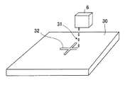
図4は、ノズルヘッドユニット6で描画対象物30にノズルヘッドユニット6に充填されたインク31でアライメントマーク32を形成する一例を示す模式的な斜視図である。描画対象物30は、図1に示す吸着テーブル3に固定されている。ここで言う描画対象物30としては、ガラス基板、シリコン基板、フィルム基板、PET基板等の基板が挙げられる。また、ここで言うアライメントマーク32の一例としてクロスラインを図4に示しているが、アライメントマーク32の形はカメラユニット7で撮像・観察でき、カメラユニット7に備わったガイドラインと位置合わせができるものであればよい。さらに、アライメントマーク32の形成は、新たにノズルヘッドユニット6を取り付けたときに行うのが好ましい。
FIG. 4 is a schematic perspective view showing an example in which the
以下、本発明のノズルヘッドを描画対象物に対して正確に位置決めするインクジェット装置を説明する。ノズルヘッドユニット6にインク31が吐出可能なノズルヘッド(図4中隠れていて見えない)を設置する。この場合、ノズルヘッドユニット6にノズルヘッドを固定するときは、精度良く加工されたキャリッジに固定することが好ましい。尚、ノズルヘッドをキャリッジに固定する際は、例えばネジ等の締結手段を用いて行うのが一般的であるが、ネジ締めに伴う締結トルクの僅かな変動によって、ノズルヘッドの位置が所定の固定位置よりずれることがあるので、特別な注意と別途の工夫が必要となる。
Hereinafter, an ink jet apparatus for accurately positioning the nozzle head of the present invention with respect to a drawing object will be described. A nozzle head (which is hidden and cannot be seen in FIG. 4) capable of ejecting
描画対象物30を吸着テーブル3に設置し、固定する。積層されたパターンが形成されていればXYZθステージ2のθ軸により、描画対象物のアライメントを行う。この場合のアライメントの効果は、新たに積層するパターンが既に形成された下地のパターンに対しθ軸方向に位置ずれが生じないようにするためである。
The drawing
通常、インクジェット装置に用いるノズルヘッドは複数のノズルを有しており、その中から本発明のノズルヘッドの位置決めに使用するノズルIを決定する。そのノズルIを備えたノズルヘッド、更にはノズルヘッドが取り付けられたノズルヘッドユニット6を用いて、描画対象物30に対し図3の描画17のシーケンスに従ってアライメントマーク32を形成する。即ち、本発明のインクジェット装置により正確に位置決めするために用いるアライメントマーク32を、ノズルヘッドユニット6及びインク31を用いて形成することになる。
Usually, a nozzle head used in an ink jet apparatus has a plurality of nozzles, and a nozzle I to be used for positioning of the nozzle head of the present invention is determined from among them. Using the nozzle head provided with the nozzle I, and further the
本発明のインクジェット装置で使用するノズルIは、ノズルの製造工程に組み込まれている検査・測定工程において、上記背景技術で説明した各種の吐出曲りに関して、ある統計誤差内の平均値に収まるものしか使用しないようにしている。そのため、各種の吐出曲りに関しては、本発明に特有の上記構成・制御と併せて問題が発生しないように工夫している。 Nozzles I used in the inkjet apparatus of the present invention are those that fall within an average value within a certain statistical error regarding the various discharge bends described in the background art in the inspection / measurement process incorporated in the nozzle manufacturing process. I do not use it. Therefore, various discharge bends have been devised so as not to cause problems in conjunction with the above-described configuration and control unique to the present invention.
形成したアライメントマーク32のある所定の位置Aの直上にノズルヘッドユニット6の位置決め操作で使用するノズルIがくるようにXYZθステージ2を動作させて位置合わせを行い、位置情報を取得する。この場合の、位置合わせは例えばノズルIとアライメントマーク32を同時に観察できるカメラの表示部で見た目上位置合わせを行うのではなく、XYZθステージ2の制御量による位置合わせのことである。つまり、ノズルヘッドの設置誤差やノズル固有の曲がりによって想定しているインク着弾位置からずれてアライメントマーク32が形成されたならば、ノズルとアライメントマーク32の位置合わせは前記の観察用のカメラの表示部ではずれたように観察される。
Positioning is performed by operating the
形成したアライメントマーク32をカメラユニット7に備わったガイドラインで位置合わせを行い、XYZθステージ2の位置情報を取得する。この時のアライメントマーク32の位置合わせを行う場所は前記の所定の位置Aである。
The
ノズルIでアライメントマーク32を形成したときに取得した位置情報と、アライメントマーク32をカメラユニット7で位置合わせを行ったときに取得した位置情報から、ノズルIとカメラユニット7の相対位置を算出する。この算出した値は、制御部11や各軸制御部12に記憶させておくことが好ましい。
From the position information acquired when the
カメラユニット7のガイドラインを用いて描画を開始したい場所に位置合わせを行う。その場所から、XYZθステージ2をノズルヘッドユニット6の方向へ前記で算出したノズルIとカメラユニット7の相対位置分の座標値を動作させる。そうすることで、描画対象物30に対してノズルヘッドユニット6を正確に位置決めすることができる。
Using the guideline of the
図5は、実際にアライメントカメラで位置合わせを実施した一例の写真である。写真上にはアライメントカメラの破線状のクロスラインのガイドライン33が表示され、ガラス基板36上に描画されたクロスライン状のアライメントマーク32を位置合わせすることができる。この場合の前記所定の位置Aとは、上記各クロスライン同士が交差する中心である。
FIG. 5 is a photograph of an example in which alignment is actually performed with an alignment camera. A broken line
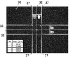
(実施例1)
図6は、本発明の実施例1に係る、インクジェット装置で実際に描画を実施した一例を示す写真である。プリンテッドエレクトロニクスにおける積層構造を有する電子デバイスとしては、例えばTFT(薄膜トランジスタ)を用いる液晶ディスプレィを想定して実施した。また、上記実施例では液晶ディスプレイを想定して実施したが、これに限定されるものではなく、TFT(薄膜トランジスタ)用いる電子デバイスとして、例えば有機ELディスプレイやエレクトロクロミックディスプレイでも良い。ノズルヘッドとしては、実施例1を始め、実施例2、後述の比較例1及び2を含め、上記電子デバイスを製作するのに必要な仕様・機能(解像度等)、所定の精度(ノズル径、吐出曲り等)を備えたものを選んで用いた。そして、特記する以外は同一の条件にて実施し、比較した。
本実施例1では、写真中央のクロスラインであるアライメントマーク32を1層目のパターン、四隅のL字ライン37を2層目のパターンとしてアライメント(調整)精度の評価を行っている。まず始めに、描画対象物としてガラス基板(日本電気硝子株式会社、OA−10G)36に対し、1層目に使用するノズルヘッドとインク(ハリマ化成株式会社、NPG−J)でクロスラインであるアライメントマーク32を描画した。その後、インクを焼結するためにガラス基板36を取り外し、オーブンで焼成した。再び、ガラス基板36を図1に示した吸着テーブル3に設置し、ガラス基板36のアライメント操作を行った。この際のガラス基板36自体のアライメント操作は、XYZθステージ2のθ軸を用いて行った。尚、インク(ハリマ化成株式会社、NPG−J)は、金(Au)ナノメタルインクである。
次に、2層目に使用するノズルヘッドとインク(ハリマ化成株式会社、NPG−J)を設置し、本発明に係る図1に示したインクジェット装置を用い、図2及びその説明に記述した操作を実施し、ノズルヘッドユニット6のアライメント操作を行った。1層目に見立てた前記のクロスライン(アライメントマーク32)の四隅にL字ライン37を新たに描画し、インクを焼結するために再びオーブンで焼成した。
Example 1
FIG. 6 is a photograph showing an example of actual drawing performed by the inkjet apparatus according to Example 1 of the present invention. As an electronic device having a laminated structure in printed electronics, for example, a liquid crystal display using a TFT (thin film transistor) was assumed. In the above embodiment, the liquid crystal display is assumed. However, the present invention is not limited to this, and an electronic device using a TFT (thin film transistor) may be, for example, an organic EL display or an electrochromic display. As a nozzle head, including Example 1, Example 2, and Comparative Examples 1 and 2 to be described later, specifications and functions (resolution, etc.) necessary for manufacturing the electronic device, predetermined accuracy (nozzle diameter, The one provided with a discharge curve etc. was selected and used. And it carried out on the same conditions except for special mention, and compared.
In the first embodiment, the alignment (adjustment) accuracy is evaluated using the
Next, the nozzle head and ink (Harima Kasei Co., Ltd., NPG-J) used in the second layer are installed, and the operation described in FIG. 2 and the description thereof is performed using the ink jet apparatus shown in FIG. 1 according to the present invention. The
1層目のクロスライン(アライメントマーク32)と2層目のL字ライン37との間隔は、設計値では1層目のラインの中心と2層目のラインの中心の間隔は50μmとしている。4ヶ所を光学顕微鏡で計測したところ、No.1=50.167μm、No.2=51.505μm、No.3=50.836μm、No.4=50.836μmであった。本計測の位置決め精度の評価では、位置ずれとしておよそ1.5μmである。
ノズルヘッドの位置決め精度に関しては、使用するインクと基板による描画後の濡れ広がり方や、使用するインクジェット装置自体の位置決め精度で異なってくる。一例として示した本計測の値からは、プリンテッドエレクトロニクスにおける積層構造を有する上記電子デバイスを製造するために十分な位置決め精度と言える結果を得た。
The distance between the first-layer cross line (alignment mark 32) and the second-layer L-shaped
The positioning accuracy of the nozzle head differs depending on how the ink to be used spreads after drawing with the substrate and the positioning accuracy of the inkjet device itself. From the value of this measurement shown as an example, a result that can be said to be a positioning accuracy sufficient for manufacturing the electronic device having a laminated structure in printed electronics was obtained.
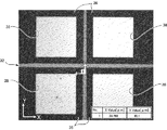
(実施例2)
図7は、本発明の実施例2に係る、インクジェット装置でノズルヘッドの位置合わせを実施した時のクロスライン(アライメントマーク32)の描画写真である。ガラス基板(日本電気硝子株式会社、OA−10G)36に対し、フォトリソグラフィによってモリブデン(Mo)を4つの正方形にパターニング(正方形パターン38)した基板を描画対象物としている。この描画対象物に対し、本発明に係るインクジェット装置でノズルヘッドを上記パターニングの中心に位置合わせを実施し、クロスライン(アライメントマーク32)をAuナノメタルインク(ハリマ化成株式会社、NPG−J)によって描画した。4つの正方形パターン38同士の距離はそれぞれ60μmであり、それぞれの正方形の中心側に向いた頂点からX軸方向及びY軸方向に30μmの位置が4つの正方形のパターニング(正方形パターン38)の中心である。光学顕微鏡の観察により、本実施例2ではX軸方向に0.769μm、Y軸方向に0.1μmずれた位置に着弾していることが分かる。パターニングの中心からのずれは、0.775μmである。本実施例2においても、本計測の値からはプリンテッドエレクトロニクスにおける積層構造を有する上記電子デバイスを製造するために十分な位置決め精度と言える結果を得た。
(Example 2)
FIG. 7 is a drawing photograph of a cross line (alignment mark 32) when the nozzle head is aligned by the ink jet apparatus according to the second embodiment of the present invention. A substrate obtained by patterning molybdenum (Mo) into four squares by photolithography (square pattern 38) on a glass substrate (Nippon Electric Glass Co., Ltd., OA-10G) 36 is used as a drawing target. With respect to this drawing object, the nozzle head is aligned with the center of the patterning in the inkjet apparatus according to the present invention, and the cross line (alignment mark 32) is made of Au nanometal ink (Halima Kasei Co., Ltd., NPG-J). Drawn. The distance between the four
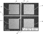
(比較例1)
図8は、位置合わせを実施していない時のクロスライン描画写真である。ガラス基板(日本電気硝子株式会社、OA−10G)36に対し、フォトリソグラフィによってモリブデン(Mo)を4つの正方形にパターニング(正方形パターン38)した基板を描画対象物としている。この描画対象物に対し、ノズルヘッドをパターニングの中心に設置してクロスライン(アライメントマーク32)をAuナノメタルインク(ハリマ化成株式会社、NPG−J)によって描画した。4つの正方形パターン38同士の距離はそれぞれ60μmであり、それぞれの正方形の中心側に向いた頂点からX軸方向及びY軸方向に30μmの位置が4つの正方形のパターニング(正方形パターン38)の中心である。光学顕微鏡の観察により、本実施例2ではX軸方向に9.264μm、Y軸方向に12.14μmずれた位置に着弾していることが分かる。パターニングの中心からのずれは、15.271μmである。実施例2と比較例1との比較により、本発明に係るインクジェット装置によって、ノズルヘッドを所定の位置に精度良く位置決めできることが分かった。
(Comparative Example 1)
FIG. 8 is a cross-line drawing photograph when alignment is not performed. A substrate obtained by patterning molybdenum (Mo) into four squares by photolithography (square pattern 38) on a glass substrate (Nippon Electric Glass Co., Ltd., OA-10G) 36 is used as a drawing target. With respect to this drawing object, a nozzle head was placed at the center of patterning, and a cross line (alignment mark 32) was drawn with Au nanometal ink (Harima Kasei Co., Ltd., NPG-J). The distance between the four
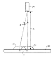
(比較例2)
図9は、所定のノズル34から描画対象物30にインク31を吐出した際の正面図である。インク31は、実線で示しているものがノズル34から描画対象物30に対し垂直に着弾(正規に着弾)したもので、破線で示しているものがノズル34から描画対象物30に対し角度θだけずれて着弾したものである。インク31の着弾のずれは、ノズル34のメニスカス挙動による吐出ずれやノズルヘッドの設置誤差による機械的なノズルの基準位置からのずれによって生じることが一般的である。ここで、ノズル34と描画対象物30間の距離をh、角度θだけずれてインクが着弾した位置と正規に着弾した位置との距離をl(エル)とするならば、下記の(1)式で表すことができる。
l=h・tanθ・・・(1)
(Comparative Example 2)
FIG. 9 is a front view when the
l = h · tanθ (1)
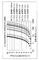
図10は、前記の関係式を元に、インク吐出の角度ずれと着弾位置ずれの関係をグラフにしたものである。ノズル−基板間の距離を、0.05mm、0.1mm、0.5mm、1mm、2mm、3mm、5mmとしてグラフに示している。一般的なインクジェットヘッドは、ノズル−描画対象物間距離を数mmオーダに制御して吐出を行うものが多い。仮に1mmの距離でインク吐出を行ったならば、実施例2で示した所定位置からのずれ0.775μmを達成するためにはノズルの角度ずれθを0.044°以内に制御しなければならない。この値は、非常に精度良くノズルヘッドを設置するだけでなく、描画対象物に対しても正確に位置合わせをしなければならず、複雑で高価なシステムを必要とする。本発明のインクジェット装置であれば、こういった問題も解決することができる。 FIG. 10 is a graph showing the relationship between the angle deviation of ink ejection and the landing position deviation based on the relational expression. The distance between the nozzle and the substrate is shown in the graph as 0.05 mm, 0.1 mm, 0.5 mm, 1 mm, 2 mm, 3 mm, and 5 mm. Many general inkjet heads perform ejection by controlling the distance between the nozzle and the drawing object to be on the order of several millimeters. If ink is ejected at a distance of 1 mm, the nozzle angular deviation θ must be controlled within 0.044 ° to achieve the deviation of 0.775 μm from the predetermined position shown in the second embodiment. . This value requires not only a nozzle head with a very high accuracy but also a precise alignment with respect to the drawing object, which requires a complicated and expensive system. Such problems can be solved by the ink jet apparatus of the present invention.
以上本発明の好ましい実施の形態について説明したが、本発明はかかる特定の実施形態に限定されるものではなく、上述の説明で特に限定していない限り、特許請求の範囲に記載された本発明の趣旨の範囲内において、種々の変形・変更が可能である。例えば、上記実施形態や実施例等に記載した技術事項を適宜組み合わせたものであってもよい。 The preferred embodiments of the present invention have been described above. However, the present invention is not limited to the specific embodiments, and the present invention described in the claims is not specifically limited by the above description. Various modifications and changes are possible within the scope of the above. For example, the technical matters described in the above embodiments and examples may be appropriately combined.
また、本発明を適用するインクジェット装置が備えるノズルヘッドは、インクの吐出機構を有する公知の全てのノズルヘッドを含むものである。例えば、液体(インク)を液滴にして吐出させるアクチュエータ手段の方式で述べると、ピエゾ方式、バブルジェット(登録商標)方式あるいは静電方式等が挙げられ、これらのノズルヘッドの位置決めにも、本発明のインクジェット装置を適用することができる。 Further, the nozzle head provided in the ink jet apparatus to which the present invention is applied includes all known nozzle heads having an ink ejection mechanism. For example, the actuator means for discharging liquid (ink) as droplets may be a piezo method, a bubble jet (registered trademark) method, an electrostatic method, or the like. The ink jet apparatus of the invention can be applied.
本発明の実施の形態に適宜記載された効果は、本発明から生じる最も好適な効果を列挙したに過ぎず、本発明による効果は、本発明の実施の形態に記載されたものに限定されるものではない。 The effects appropriately described in the embodiments of the present invention are merely a list of the most preferable effects resulting from the present invention, and the effects of the present invention are limited to those described in the embodiments of the present invention. It is not a thing.
1 定盤
2 XYZθステージ(ステージの一例)
2X X軸移動ステージ(ステージの一例)
2Y Y軸移動ステージ(ステージの一例)
3 吸着テーブル(テーブル)
4 ガントリ
5 ガントリZステージ
6 ノズルヘッドユニット(マーク形成手段、ノズルヘッドを備える)
7 カメラユニット(撮像手段を備える)
8 X軸ガイドレール(移動手段を構成)
9 Y軸ガイドレール(移動手段を構成)
10 除振台
11 制御部(制御手段、算出手段の一例)
12 各軸制御部(制御手段、算出手段の一例)
13 位置検出部
14 記憶部(記憶手段の一例)
15 吐出機構(インクの吐出機構)
16 前処理
17 描画
18 描画中の動作及び速度の指示
19 吐出位置の指示
20 吐出パラメータの指示
21 描画中のステージ動作
22 吐出位置検出
23 吐出トリガ
24 インク吐出
25 ノズルをアライメントマーク所定箇所へ位置合わせ
26 ノズルのステージ位置座標取得
27 アライメントマークをカメラガイドラインへ位置合わせ
28 カメラのステージ位置座標取得
29 ノズルとカメラの相対位置算出
30 描画対象物(対象物の一例)
31 インク
32 アライメントマーク
33 ガイドライン(位置合わせ手段)
34 ノズル
35 制御装置
36 ガラス基板
37 L字ライン
38 正方形パターン
1
2X X-axis moving stage (an example of a stage)
2Y Y-axis moving stage (an example of a stage)
3 Suction table (table)
4
7 Camera unit (equipped with imaging means)
8 X-axis guide rail (composes moving means)
9 Y-axis guide rail (composes moving means)
10 vibration isolation table 11 control unit (an example of control means and calculation means)
12 Each axis control part (an example of a control means and a calculation means)
13 position detection part 14 storage part (an example of storage means)
15 Discharge mechanism (ink discharge mechanism)
16
31
34
Claims (5)
対象物を載置するテーブルを任意の位置に移動するステージと、
前記吐出機構から吐出されるインクによって形成されたアライメントマークを撮像する撮像手段と、
前記対象物に前記アライメントマークを形成する際の前記ステージの第1の位置情報と、前記アライメントマークを前記撮像手段で撮像する際の前記ステージの第2の位置情報とを記憶する記憶手段と、
前記記憶手段に記憶された前記第1の位置情報と、前記第2の位置情報とから、前記ノズルヘッドと前記撮像手段との相対位置を算出する算出手段と、
前記算出手段により算出された結果に基づいて、前記ステージを移動する制御手段と、
を備え、
前記撮像手段は、前記アライメントマークの形成位置に位置合わせするための位置合わせ手段を有し、前記第2の位置情報を取得するインクジェット装置。 A nozzle head having an ink ejection mechanism;
A stage for moving a table on which an object is placed to an arbitrary position;
Imaging means for imaging an alignment mark formed by ink ejected from the ejection mechanism;
Storage means for storing first position information of the stage when the alignment mark is formed on the object and second position information of the stage when the alignment mark is imaged by the imaging means ;
Calculating means for calculating a relative position between the nozzle head and the imaging means from the first position information and the second position information stored in the storage means ;
Control means for moving the stage based on the result calculated by the calculation means;
Equipped with a,
The image pickup unit includes an alignment unit for aligning with a formation position of the alignment mark, and acquires the second position information .
Priority Applications (1)
| Application Number | Priority Date | Filing Date | Title |
|---|---|---|---|
| JP2014096129A JP6331663B2 (en) | 2014-05-07 | 2014-05-07 | Inkjet device |
Applications Claiming Priority (1)
| Application Number | Priority Date | Filing Date | Title |
|---|---|---|---|
| JP2014096129A JP6331663B2 (en) | 2014-05-07 | 2014-05-07 | Inkjet device |
Related Child Applications (1)
| Application Number | Title | Priority Date | Filing Date |
|---|---|---|---|
| JP2018088267A Division JP2018122304A (en) | 2018-05-01 | 2018-05-01 | Ink jet device, nozzle head positioning method and program |
Publications (2)
| Publication Number | Publication Date |
|---|---|
| JP2015213848A JP2015213848A (en) | 2015-12-03 |
| JP6331663B2 true JP6331663B2 (en) | 2018-05-30 |
Family
ID=54751291
Family Applications (1)
| Application Number | Title | Priority Date | Filing Date |
|---|---|---|---|
| JP2014096129A Active JP6331663B2 (en) | 2014-05-07 | 2014-05-07 | Inkjet device |
Country Status (1)
| Country | Link |
|---|---|
| JP (1) | JP6331663B2 (en) |
Cited By (1)
| Publication number | Priority date | Publication date | Assignee | Title |
|---|---|---|---|---|
| CN111376590A (en) * | 2018-12-29 | 2020-07-07 | Tcl集团股份有限公司 | Ink-jet printing equipment and ink-jet printing method and device thereof |
Families Citing this family (6)
| Publication number | Priority date | Publication date | Assignee | Title |
|---|---|---|---|---|
| JP6848663B2 (en) * | 2017-05-10 | 2021-03-24 | セイコーエプソン株式会社 | Printing device and control method |
| JP6948574B2 (en) * | 2018-05-31 | 2021-10-13 | パナソニックIpマネジメント株式会社 | Flat panel display board position adjustment device and flat panel display board position adjustment method |
| CN113492591A (en) * | 2020-03-19 | 2021-10-12 | 深圳市汉森软件有限公司 | Printing method, device, equipment and storage medium with image acquisition device as auxiliary |
| JP7559407B2 (en) * | 2020-07-31 | 2024-10-02 | Toppanホールディングス株式会社 | Manufacturing method of decorative sheet |
| CN116552143B (en) * | 2023-07-12 | 2023-09-12 | 苏州优备精密智能装备股份有限公司 | Cross gantry type printing adjusting device and detection adjusting method thereof |
| CN117119115B (en) * | 2023-10-23 | 2024-02-06 | 杭州百子尖科技股份有限公司 | Calibration methods, devices, electronic equipment and storage media based on machine vision |
Family Cites Families (3)
| Publication number | Priority date | Publication date | Assignee | Title |
|---|---|---|---|---|
| JP2001286812A (en) * | 2000-04-07 | 2001-10-16 | Dainippon Printing Co Ltd | How to apply colorant |
| JP4121014B2 (en) * | 2002-07-18 | 2008-07-16 | アスリートFa株式会社 | Needle position correction method and potting device |
| JP4168728B2 (en) * | 2002-10-23 | 2008-10-22 | セイコーエプソン株式会社 | Method for correcting dot position of droplet discharge device, droplet discharge method, and electro-optical device manufacturing method |
-
2014
- 2014-05-07 JP JP2014096129A patent/JP6331663B2/en active Active
Cited By (2)
| Publication number | Priority date | Publication date | Assignee | Title |
|---|---|---|---|---|
| CN111376590A (en) * | 2018-12-29 | 2020-07-07 | Tcl集团股份有限公司 | Ink-jet printing equipment and ink-jet printing method and device thereof |
| CN111376590B (en) * | 2018-12-29 | 2021-07-27 | Tcl科技集团股份有限公司 | Ink-jet printing equipment and ink-jet printing method and device thereof |
Also Published As
| Publication number | Publication date |
|---|---|
| JP2015213848A (en) | 2015-12-03 |
Similar Documents
| Publication | Publication Date | Title |
|---|---|---|
| JP6331663B2 (en) | Inkjet device | |
| CN108569042B (en) | Workpiece processing device, workpiece processing method, and computer storage medium | |
| CN108569041B (en) | Droplet discharge device, droplet discharge method, and computer storage medium | |
| TWI810096B (en) | Inkjet printer | |
| JP6296699B2 (en) | Printing device | |
| CN109823050B (en) | Inkjet printing-oriented droplet ejection multi-stage positioning error compensation method and device | |
| CN108568382B (en) | Droplet discharge device, droplet discharge method, program, and computer storage medium | |
| JP5556661B2 (en) | Inkjet drawing device | |
| TWI221125B (en) | Inkjet deposition apparatus and method | |
| JP2007144397A (en) | Method and apparatus for ink jet printing on a non-planar substrate. | |
| CN101584035B (en) | Substrate processing apparatus and substrate processing method | |
| US8348368B2 (en) | Method for arraying head assemblies of inkjet printer and apparatus for performing the same | |
| JP2018008210A (en) | Coating apparatus and coating method | |
| JP2018122304A (en) | Ink jet device, nozzle head positioning method and program | |
| JP2008147291A (en) | Substrate support apparatus, substrate support method, substrate processing apparatus, substrate processing method, and manufacturing method of display device constituent member | |
| JP2009239155A (en) | Positioning device and controlling method of positioning device | |
| JP2008046628A (en) | Alignment mask and dot position recognition method | |
| JP2006258845A (en) | Pattern forming apparatus and head correction method | |
| JP5495528B2 (en) | Inkjet recording apparatus and inkjet recording method | |
| JP2016140775A (en) | Droplet ejection system, position adjustment method and program | |
| JP2006239976A (en) | Pattern forming apparatus and position correction method | |
| JP2012086194A (en) | Drawing device and drawing method | |
| JP2007152215A (en) | Pattern forming apparatus and pattern forming method | |
| JP2022035649A (en) | Ink jet printer and ink jet printing method | |
| JP2011255292A (en) | Positioning method, positioning device, droplet application method, liquid application apparatus, and reference plate |
Legal Events
| Date | Code | Title | Description |
|---|---|---|---|
| A621 | Written request for application examination |
Free format text: JAPANESE INTERMEDIATE CODE: A621 Effective date: 20170421 |
|
| A977 | Report on retrieval |
Free format text: JAPANESE INTERMEDIATE CODE: A971007 Effective date: 20171225 |
|
| A131 | Notification of reasons for refusal |
Free format text: JAPANESE INTERMEDIATE CODE: A131 Effective date: 20180109 |
|
| A521 | Written amendment |
Free format text: JAPANESE INTERMEDIATE CODE: A523 Effective date: 20180312 |
|
| TRDD | Decision of grant or rejection written | ||
| A01 | Written decision to grant a patent or to grant a registration (utility model) |
Free format text: JAPANESE INTERMEDIATE CODE: A01 Effective date: 20180403 |
|
| A61 | First payment of annual fees (during grant procedure) |
Free format text: JAPANESE INTERMEDIATE CODE: A61 Effective date: 20180416 |
|
| R151 | Written notification of patent or utility model registration |
Ref document number: 6331663 Country of ref document: JP Free format text: JAPANESE INTERMEDIATE CODE: R151 |