JP6330507B2 - Image processing apparatus and image processing method - Google Patents
Image processing apparatus and image processing method Download PDFInfo
- Publication number
- JP6330507B2 JP6330507B2 JP2014125966A JP2014125966A JP6330507B2 JP 6330507 B2 JP6330507 B2 JP 6330507B2 JP 2014125966 A JP2014125966 A JP 2014125966A JP 2014125966 A JP2014125966 A JP 2014125966A JP 6330507 B2 JP6330507 B2 JP 6330507B2
- Authority
- JP
- Japan
- Prior art keywords
- layer
- unit
- image
- granularity
- lookup table
- Prior art date
- Legal status (The legal status is an assumption and is not a legal conclusion. Google has not performed a legal analysis and makes no representation as to the accuracy of the status listed.)
- Expired - Fee Related
Links
Images


Classifications
-
- H—ELECTRICITY
- H04—ELECTRIC COMMUNICATION TECHNIQUE
- H04N—PICTORIAL COMMUNICATION, e.g. TELEVISION
- H04N19/00—Methods or arrangements for coding, decoding, compressing or decompressing digital video signals
- H04N19/30—Methods or arrangements for coding, decoding, compressing or decompressing digital video signals using hierarchical techniques, e.g. scalability
- H04N19/34—Scalability techniques involving progressive bit-plane based encoding of the enhancement layer, e.g. fine granular scalability [FGS]
-
- H—ELECTRICITY
- H04—ELECTRIC COMMUNICATION TECHNIQUE
- H04N—PICTORIAL COMMUNICATION, e.g. TELEVISION
- H04N19/00—Methods or arrangements for coding, decoding, compressing or decompressing digital video signals
- H04N19/30—Methods or arrangements for coding, decoding, compressing or decompressing digital video signals using hierarchical techniques, e.g. scalability
- H04N19/33—Methods or arrangements for coding, decoding, compressing or decompressing digital video signals using hierarchical techniques, e.g. scalability in the spatial domain
-
- H—ELECTRICITY
- H04—ELECTRIC COMMUNICATION TECHNIQUE
- H04N—PICTORIAL COMMUNICATION, e.g. TELEVISION
- H04N19/00—Methods or arrangements for coding, decoding, compressing or decompressing digital video signals
- H04N19/46—Embedding additional information in the video signal during the compression process
- H04N19/463—Embedding additional information in the video signal during the compression process by compressing encoding parameters before transmission
-
- H—ELECTRICITY
- H04—ELECTRIC COMMUNICATION TECHNIQUE
- H04N—PICTORIAL COMMUNICATION, e.g. TELEVISION
- H04N19/00—Methods or arrangements for coding, decoding, compressing or decompressing digital video signals
- H04N19/50—Methods or arrangements for coding, decoding, compressing or decompressing digital video signals using predictive coding
- H04N19/59—Methods or arrangements for coding, decoding, compressing or decompressing digital video signals using predictive coding involving spatial sub-sampling or interpolation, e.g. alteration of picture size or resolution
-
- H—ELECTRICITY
- H04—ELECTRIC COMMUNICATION TECHNIQUE
- H04N—PICTORIAL COMMUNICATION, e.g. TELEVISION
- H04N19/00—Methods or arrangements for coding, decoding, compressing or decompressing digital video signals
- H04N19/70—Methods or arrangements for coding, decoding, compressing or decompressing digital video signals characterised by syntax aspects related to video coding, e.g. related to compression standards
-
- H—ELECTRICITY
- H04—ELECTRIC COMMUNICATION TECHNIQUE
- H04N—PICTORIAL COMMUNICATION, e.g. TELEVISION
- H04N19/00—Methods or arrangements for coding, decoding, compressing or decompressing digital video signals
- H04N19/90—Methods or arrangements for coding, decoding, compressing or decompressing digital video signals using coding techniques not provided for in groups H04N19/10-H04N19/85, e.g. fractals
- H04N19/96—Tree coding, e.g. quad-tree coding
-
- H—ELECTRICITY
- H04—ELECTRIC COMMUNICATION TECHNIQUE
- H04N—PICTORIAL COMMUNICATION, e.g. TELEVISION
- H04N19/00—Methods or arrangements for coding, decoding, compressing or decompressing digital video signals
- H04N19/10—Methods or arrangements for coding, decoding, compressing or decompressing digital video signals using adaptive coding
- H04N19/102—Methods or arrangements for coding, decoding, compressing or decompressing digital video signals using adaptive coding characterised by the element, parameter or selection affected or controlled by the adaptive coding
- H04N19/103—Selection of coding mode or of prediction mode
- H04N19/105—Selection of the reference unit for prediction within a chosen coding or prediction mode, e.g. adaptive choice of position and number of pixels used for prediction
-
- H—ELECTRICITY
- H04—ELECTRIC COMMUNICATION TECHNIQUE
- H04N—PICTORIAL COMMUNICATION, e.g. TELEVISION
- H04N19/00—Methods or arrangements for coding, decoding, compressing or decompressing digital video signals
- H04N19/10—Methods or arrangements for coding, decoding, compressing or decompressing digital video signals using adaptive coding
- H04N19/134—Methods or arrangements for coding, decoding, compressing or decompressing digital video signals using adaptive coding characterised by the element, parameter or criterion affecting or controlling the adaptive coding
- H04N19/157—Assigned coding mode, i.e. the coding mode being predefined or preselected to be further used for selection of another element or parameter
- H04N19/159—Prediction type, e.g. intra-frame, inter-frame or bidirectional frame prediction
-
- H—ELECTRICITY
- H04—ELECTRIC COMMUNICATION TECHNIQUE
- H04N—PICTORIAL COMMUNICATION, e.g. TELEVISION
- H04N19/00—Methods or arrangements for coding, decoding, compressing or decompressing digital video signals
- H04N19/10—Methods or arrangements for coding, decoding, compressing or decompressing digital video signals using adaptive coding
- H04N19/169—Methods or arrangements for coding, decoding, compressing or decompressing digital video signals using adaptive coding characterised by the coding unit, i.e. the structural portion or semantic portion of the video signal being the object or the subject of the adaptive coding
- H04N19/186—Methods or arrangements for coding, decoding, compressing or decompressing digital video signals using adaptive coding characterised by the coding unit, i.e. the structural portion or semantic portion of the video signal being the object or the subject of the adaptive coding the unit being a colour or a chrominance component
-
- H—ELECTRICITY
- H04—ELECTRIC COMMUNICATION TECHNIQUE
- H04N—PICTORIAL COMMUNICATION, e.g. TELEVISION
- H04N19/00—Methods or arrangements for coding, decoding, compressing or decompressing digital video signals
- H04N19/10—Methods or arrangements for coding, decoding, compressing or decompressing digital video signals using adaptive coding
- H04N19/169—Methods or arrangements for coding, decoding, compressing or decompressing digital video signals using adaptive coding characterised by the coding unit, i.e. the structural portion or semantic portion of the video signal being the object or the subject of the adaptive coding
- H04N19/187—Methods or arrangements for coding, decoding, compressing or decompressing digital video signals using adaptive coding characterised by the coding unit, i.e. the structural portion or semantic portion of the video signal being the object or the subject of the adaptive coding the unit being a scalable video layer
Description
本開示は、画像処理装置及び画像処理方法に関する。 The present disclosure relates to an image processing apparatus and an image processing method.
ITU−TとISO/IECとの共同の標準化団体であるJCTVC(Joint Collaboration Team-Video Coding)は、H.264/AVCよりも符号化効率をさらに向上させることを目的として、HEVC(High Efficiency Video Coding)と呼ばれる画像符号化方式の標準化を進めてきた(例えば、非特許文献1参照)。HEVCは、シングルレイヤの符号化のみならず、スケーラブル符号化をも提供する。HEVCのスケーラブル符号化技術を、SHVC(Scalable HEVC)ともいう(例えば、非特許文献2参照)。 JCTVC (Joint Collaboration Team-Video Coding), a joint standardization organization of ITU-T and ISO / IEC, For the purpose of further improving the encoding efficiency over H.264 / AVC, standardization of an image encoding method called HEVC (High Efficiency Video Coding) has been advanced (for example, see Non-Patent Document 1). HEVC provides not only single layer coding but also scalable coding. HEVC scalable coding technology is also referred to as SHVC (Scalable HEVC) (see, for example, Non-Patent Document 2).
スケーラブル符号化とは、一般には、粗い画像信号を伝送するレイヤと精細な画像信号を伝送するレイヤとを階層的に符号化する技術をいう。従来のスケーラブル符号化技術において階層化され得る典型的な属性は、空間解像度(空間スケーラビリティ)、フレームレート(時間スケーラビリティ)及びSN比(SNR(Signal to Noise Ratio)スケーラビリティ)の3種類であった。これに対し、非特許文献3は、画素属性の一種である色域(Color Gamut)を階層化する色域スケーラビリティを提案している。色域と共に、ビット深度もまた階層化され得る。非特許文献4は、やはり画素属性の一種である輝度ダイナミックレンジを階層化する技術を提案している。
Scalable encoding generally refers to a technique for hierarchically encoding a layer that transmits a coarse image signal and a layer that transmits a fine image signal. There are three typical attributes that can be hierarchized in the conventional scalable coding technology: spatial resolution (spatial scalability), frame rate (temporal scalability), and SN ratio (SNR (Signal to Noise Ratio) scalability). On the other hand, Non-Patent
非特許文献3により提案された手法によれば、ベースレイヤの色域(例えば、ITU−R BT.709)における画素ベクトル(Y,U,V)から、3次元のルックアップテーブルを用いて、エンハンスメントレイヤの色域(例えば、ITU−R BT.2020)における対応する画素ベクトルが予測される。このルックアップテーブルは、カラーマッピングテーブルという名称でSHVCの標準仕様において採用される見込みである。カラーマッピングテーブルは、ベースレイヤの色空間をいくつかの直方体状の区画(cuboid partition)に分割する。カラーマッピングテーブルは、分割によって形成される複数の区画の各々を、対応するエンハンスメントレイヤの色空間の部分空間にマッピングする。1つの部分空間は、4つの頂点を定義することによって特定され得る。非特許文献3により提案された手法によれば、具体的な予測画素値は、4つの頂点の画素値に基づく三角錐補間(tetrahedral interpolation)によって決定される。
According to the method proposed by Non-Patent
カラーマッピングテーブルによる空間分割の粒度がより精細であるほど、ベースレイヤの色空間の区画数はより多くなり、対応するエンハンスメントレイヤの複数の部分空間を定義するために要する符号量も増大する。一方、空間分割の粒度がより粗ければ、カラーマッピングテーブルのために要する符号量はより少ないが、インターレイヤ予測の予測精度が低下し得る。しかし、既存の手法では、3つの色成分について画一的な(即ち1通りの)分割の粒度しか定義することができない。そのため、ある色成分の予測のために最適な粒度でベースレイヤの色空間を分割した場合に、他の色成分の予測にとっては粒度が粗すぎて十分な予測精度が得られず、又は必要以上に粒度が精細すぎることがある。 As the granularity of space division by the color mapping table becomes finer, the number of sections in the color space of the base layer increases, and the amount of code required to define a plurality of subspaces in the corresponding enhancement layer also increases. On the other hand, if the granularity of the spatial division is coarser, the amount of code required for the color mapping table is smaller, but the prediction accuracy of the inter-layer prediction may be reduced. However, in the existing method, only uniform (that is, one) division granularity can be defined for the three color components. Therefore, when the base layer color space is divided at an optimal granularity for predicting a certain color component, the granularity is too coarse for predicting other color components, and sufficient prediction accuracy cannot be obtained, or more than necessary. The grain size may be too fine.
そこで、ルックアップテーブル方式のスケーラブル符号化技術において、色空間の分割の粒度をより柔軟に扱うことのできる手法が提供されることが望ましい。 Therefore, it is desirable to provide a technique that can handle the granularity of color space division more flexibly in the lookup table type scalable coding technique.
本開示によれば、第1レイヤの輝度成分、第1色差成分及び第2色差成分の組合せと当該組合せに対応する第2レイヤの予測画素値とをマッピングするルックアップテーブルを用いて、前記第1レイヤの画像から、前記第1レイヤとは異なる画素属性を有する前記第2レイヤの画像を予測する予測部、を備え、前記予測部は、第1のルックアップテーブルを用いて前記第2レイヤの前記輝度成分の予測値を取得し、前記第1のルックアップテーブルとは粒度の異なる第2のルックアップテーブルを用いて前記第2レイヤの前記第1色差成分の予測値を取得する、画像処理装置が提供される。 According to the present disclosure, using the lookup table that maps the luminance component of the first layer, the first color difference component, and the second color difference component and the predicted pixel value of the second layer corresponding to the combination, the first layer is used. A prediction unit that predicts an image of the second layer having a pixel attribute different from that of the first layer from an image of the first layer, the prediction unit using the first lookup table, the second layer An estimated value of the luminance component of the first layer, and a predicted value of the first color difference component of the second layer using a second look-up table having a different granularity from the first look-up table. A processing device is provided.
上記画像処理装置は、画像を復号する画像復号装置として実現されてもよく、又は、画像を符号化する画像符号化装置として実現されてもよい。 The image processing apparatus may be realized as an image decoding apparatus that decodes an image, or may be realized as an image encoding apparatus that encodes an image.
また、本開示によれば、第1レイヤの画像から、前記第1レイヤとは異なる画素属性を有する第2レイヤの画像を予測する画像処理装置において、前記第1レイヤの輝度成分、第1色差成分及び第2色差成分の組合せと当該組合せに対応する前記第2レイヤの予測画素値とをマッピングする第1のルックアップテーブルを用いて、前記第2レイヤの前記輝度成分の予測値を取得することと、前記第1のルックアップテーブルとは粒度の異なる第2のルックアップテーブルを用いて、前記第2レイヤの前記第1色差成分の予測値を取得することと、を含む画像処理方法が提供される。 According to the present disclosure, in the image processing apparatus that predicts a second layer image having a pixel attribute different from that of the first layer from the first layer image, the luminance component of the first layer, the first color difference, and the like. A predicted value of the luminance component of the second layer is acquired using a first lookup table that maps a combination of a component and a second color difference component and a predicted pixel value of the second layer corresponding to the combination. And obtaining a predicted value of the first color difference component of the second layer using a second look-up table having a different granularity from the first look-up table. Provided.
本開示に係る技術によれば、ルックアップテーブル方式のスケーラブル符号化技術において、色空間の分割の粒度をより柔軟に扱うことが可能となる。
なお、上記の効果は必ずしも限定的なものではなく、上記の効果と共に、又は上記の効果に代えて、本明細書に示されたいずれかの効果、又は本明細書から把握され得る他の効果が奏されてもよい。
According to the technique according to the present disclosure, it is possible to handle the granularity of color space division more flexibly in the look-up table type scalable encoding technique.
Note that the above effects are not necessarily limited, and any of the effects shown in the present specification, or other effects that can be grasped from the present specification, together with or in place of the above effects. May be played.
以下に添付図面を参照しながら、本開示の好適な実施の形態について詳細に説明する。なお、本明細書及び図面において、実質的に同一の機能構成を有する構成要素については、同一の符号を付することにより重複説明を省略する。 Hereinafter, preferred embodiments of the present disclosure will be described in detail with reference to the accompanying drawings. In addition, in this specification and drawing, about the component which has the substantially same function structure, duplication description is abbreviate | omitted by attaching | subjecting the same code | symbol.
また、以下の順序で説明を行う。
1.概要
1−1.スケーラブル符号化
1−2.ルックアップテーブル方式でのインターレイヤ予測
1−3.エンコーダの基本的な構成例
1−4.デコーダの基本的な構成例
2.一実施形態に係るEL符号化部の構成例
2−1.各部の説明
2−2.シンタックス例
3.一実施形態に係る符号化時の処理の流れ
3−1.概略的な流れ
3−2.空間分割処理
3−3.テーブル情報符号化処理
4.一実施形態に係るEL復号部の構成例
5.一実施形態に係る復号時の処理の流れ
5−1.概略的な流れ
5−2.テーブル再構築処理
6.応用例
6−1.様々な製品への応用
6−2.スケーラブル符号化の様々な用途
6−3.その他
7.まとめ
The description will be given in the following order.
1. Outline 1-1. Scalable coding 1-2. Inter-layer prediction by lookup table method 1-3. Basic configuration example of encoder 1-4. 1. Basic configuration example of decoder Example of configuration of EL encoding unit according to embodiment 2-1. Explanation of each part 2-2. Syntax example 2. 3. Process flow during encoding according to one embodiment 3-1. Schematic flow 3-2. Spatial division processing 3-3. Table
<1.概要>
[1−1.スケーラブル符号化]
スケーラブル符号化においては、一連の画像をそれぞれ含む複数のレイヤが符号化される。ベースレイヤ(base layer)は、最初に符号化される、最も粗い画像を表現するレイヤである。ベースレイヤの符号化ストリームは、他のレイヤの符号化ストリームを復号することなく、独立して復号され得る。ベースレイヤ以外のレイヤは、エンハンスメントレイヤ(enhancement layer)と呼ばれる、より精細な画像を表現するレイヤである。エンハンスメントレイヤの符号化ストリームは、ベースレイヤの符号化ストリームに含まれる情報を用いて符号化される。従って、エンハンスメントレイヤの画像を再現するためには、ベースレイヤ及びエンハンスメントレイヤの双方の符号化ストリームが復号されることになる。スケーラブル符号化において扱われるレイヤの数は、2つ以上のいかなる数であってもよい。3つ以上のレイヤが符号化される場合には、最下位のレイヤがベースレイヤ、残りの複数のレイヤがエンハンスメントレイヤである。より上位のエンハンスメントレイヤの符号化ストリームは、より下位のエンハンスメントレイヤ又はベースレイヤの符号化ストリームに含まれる情報を用いて符号化され及び復号され得る。
<1. Overview>
[1-1. Scalable coding]
In scalable encoding, a plurality of layers each including a series of images are encoded. The base layer is a layer that expresses the coarsest image that is encoded first. The base layer coded stream may be decoded independently without decoding the other layer coded streams. A layer other than the base layer is a layer called an enhancement layer (enhancement layer) that represents a finer image. The enhancement layer encoded stream is encoded using information included in the base layer encoded stream. Accordingly, in order to reproduce the enhancement layer image, both the base layer and enhancement layer encoded streams are decoded. The number of layers handled in scalable coding may be any number of two or more. When three or more layers are encoded, the lowest layer is the base layer, and the remaining layers are enhancement layers. The higher enhancement layer encoded stream may be encoded and decoded using information contained in the lower enhancement layer or base layer encoded stream.
図1は、スケーラブル符号化される3つのレイヤL1、L2及びL3を示している。レイヤL1はベースレイヤであり、レイヤL2及びL3はエンハンスメントレイヤである。レイヤL2のレイヤL1に対する空間解像度の比は、2:1である。レイヤL3のレイヤL1に対する空間解像度の比は、4:1である。なお、ここでの解像度比は一例に過ぎず、例えば1.5:1などの非整数の解像度比が使用されてもよい。レイヤL1のブロックB1は、ベースレイヤのピクチャ内の符号化処理の処理単位である。レイヤL2のブロックB2は、ブロックB1と共通するシーンを映したエンハンスメントレイヤのピクチャ内の符号化処理の処理単位である。ブロックB2は、レイヤL1のブロックB1に対応する。レイヤL3のブロックB3は、ブロックB1及びB2と共通するシーンを映したより上位のエンハンスメントレイヤのピクチャ内の符号化処理の処理単位である。ブロックB3は、レイヤL1のブロックB1及びレイヤL2のブロックB2に対応する。 FIG. 1 shows three layers L1, L2 and L3 that are scalable coded. Layer L1 is a base layer, and layers L2 and L3 are enhancement layers. The ratio of the spatial resolution of the layer L2 to the layer L1 is 2: 1. The ratio of the spatial resolution of layer L3 to layer L1 is 4: 1. The resolution ratio here is only an example, and a non-integer resolution ratio such as 1.5: 1 may be used. The block B1 of the layer L1 is a processing unit of the encoding process in the base layer picture. The block B2 of the layer L2 is a processing unit of the encoding process in the enhancement layer picture that shows a scene common to the block B1. Block B2 corresponds to block B1 of layer L1. The block B3 of the layer L3 is a processing unit for encoding processing in a picture of a higher enhancement layer that shows a scene common to the blocks B1 and B2. The block B3 corresponds to the block B1 of the layer L1 and the block B2 of the layer L2.
図1に例示したレイヤ構造において、画像のテクスチャは、共通するシーンを映したレイヤ間で類似する。即ち、レイヤL1内のブロックB1、レイヤL2内のブロックB2、及びレイヤL3内のブロックB3のテクスチャは類似する。従って、例えばブロックB1を参照ブロックとして用いてブロックB2又はブロックB3の画素を予測し、又はブロックB2を参照ブロックとして用いてブロックB3の画素を予測すれば、高い予測精度が得られる可能性がある。このようなレイヤ間の予測を、インターレイヤ予測という。インターレイヤ予測に分類される具体的な予測手法は、複数存在する。その一例は、ベースレイヤの復号画像(リコンストラクト画像)からエンハンスメントレイヤの復号画像を予測する、イントラBL予測である。他の例は、ベースレイヤの予測誤差(残差)画像からエンハンスメントレイヤの予測誤差画像を予測する、イントラ残差予測及びインター残差予測である。 In the layer structure illustrated in FIG. 1, the texture of an image is similar between layers that show a common scene. That is, the textures of the block B1 in the layer L1, the block B2 in the layer L2, and the block B3 in the layer L3 are similar. Therefore, for example, if the pixel of the block B2 or the block B3 is predicted using the block B1 as the reference block, or the pixel of the block B3 is predicted using the block B2 as the reference block, high prediction accuracy may be obtained. . Such prediction between layers is called inter-layer prediction. There are a plurality of specific prediction methods classified as inter-layer prediction. One example is intra-BL prediction that predicts an enhancement layer decoded image from a base layer decoded image (reconstructed image). Another example is intra residual prediction and inter residual prediction, in which an enhancement layer prediction error image is predicted from a base layer prediction error (residual) image.
[1−2.ルックアップテーブル方式でのインターレイヤ予測]
(1)色域スケーラビリティ
図1に例示した空間スケーラビリティでは、アップサンプリングによって画素を補間することにより、インターレイヤ予測の予測画素が形成される。これに対し、非特許文献3により提案されたルックアップテーブル方式でのインターレイヤ予測は、色域スケーラビリティのような、画素属性が階層化される場合のスケーラブル符号化に適した手法である。画素属性が階層化される場合には、同じ空間的及び時間的位置の画素であっても、画素値がレイヤ間で異なる可能性がある。
[1-2. Inter-layer prediction using lookup table method]
(1) Color Gamut Scalability In the spatial scalability illustrated in FIG. 1, prediction pixels for inter-layer prediction are formed by interpolating pixels by upsampling. On the other hand, the inter-layer prediction using the lookup table method proposed by
一例として、ベースレイヤであるレイヤL1の画像がHDテレビジョン画像であり、エンハンスメントレイヤであるレイヤL2の画像がUHDテレビジョン画像であるものとする。図2は、BT.709及びBT.2020により表現される色域について説明するための説明図である。図2を参照すると、所定の拘束条件を用いて3次元の色空間を2次元平面へマッピングした色域グラフが示されている。グラフ中の十字マークは、白色がマッピングされる位置を示す。グラフ中の破線は、BT.709が表現することのできる色の範囲を示す。グラフ中の実線は、BT.2020が表現することのできる色の範囲を示す。グラフ中の点線は、人間の視覚が識別することのできる色の範囲を示す。図2から理解されるように、BT.2020は、BT.709よりも多彩な色を表現することができる。レイヤL1からレイヤL2へのインターレイヤ予測に際しては、レイヤL1の各画素にマッピングされるレイヤL2の予測画素値が、3次元のルックアップテーブルに基づいて取得され得る。アップサンプリングは、ルックアップテーブルへ入力される入力画素値について行われてもよく、又はルックアップテーブルに基づいて取得される予測画素値について行われてもよい。予測画素値に別途符号化され及び復号され得る残差(予測誤差)を加算することで、エンハンスメントレイヤの画素値が復元される。 As an example, it is assumed that the image of the layer L1 that is the base layer is an HD television image, and the image of the layer L2 that is the enhancement layer is a UHD television image. FIG. 709 and BT. 4 is an explanatory diagram for describing a color gamut expressed by 2020. FIG. Referring to FIG. 2, there is shown a color gamut graph in which a three-dimensional color space is mapped to a two-dimensional plane using predetermined constraint conditions. The cross mark in the graph indicates the position where white is mapped. The broken line in the graph indicates BT. Reference numeral 709 denotes a range of colors that can be expressed. The solid line in the graph is BT. The range of colors that 2020 can represent is shown. The dotted lines in the graph indicate the range of colors that human vision can identify. As can be seen from FIG. 2020 is BT. More colors than 709 can be expressed. In the inter-layer prediction from the layer L1 to the layer L2, the predicted pixel value of the layer L2 mapped to each pixel of the layer L1 can be acquired based on a three-dimensional lookup table. Upsampling may be performed on input pixel values input to the lookup table, or may be performed on predicted pixel values obtained based on the lookup table. By adding a residual (prediction error) that can be separately encoded and decoded to the predicted pixel value, the pixel value of the enhancement layer is restored.
(2)ダイナミックレンジスケーラビリティ
ルックアップテーブル方式は、色域スケーラビリティに限定されず、他の種類のスケーラブル符号化にも適用可能である。例えば、ダイナミックレンジ又はビット深度といった画素属性の変換のために、ルックアップテーブルによって変換の前後の画素値の最適なマッピングを定義することが可能である。
(2) Dynamic Range Scalability The lookup table method is not limited to color gamut scalability, and can be applied to other types of scalable coding. For example, for the conversion of pixel attributes such as dynamic range or bit depth, it is possible to define an optimal mapping of pixel values before and after conversion by means of a lookup table.
輝度ダイナミックレンジは、画質に影響を与える重要な属性である。既存の多くのディスプレイによりサポートされるSDR(Standard Dynamic Range)画像の最大輝度は、100nitである。一方、近年市場に投入されたハイエンドディスプレイによりサポートされるHDR(High Dynamic Range)画像の最大輝度は、例えば800nitに達する。SDR画像は、HDR画像との対比において、LDR(Low Dynamic Range)画像とも呼ばれる。 The luminance dynamic range is an important attribute that affects the image quality. The maximum luminance of a standard dynamic range (SDR) image supported by many existing displays is 100 nits. On the other hand, the maximum brightness of an HDR (High Dynamic Range) image supported by a high-end display put on the market in recent years reaches, for example, 800 nits. The SDR image is also referred to as an LDR (Low Dynamic Range) image in contrast to the HDR image.
図3は、ビデオフォーマットのダイナミックレンジについて説明するための説明図である。図3の縦軸は輝度[nit]を表す。自然界の最大輝度は20000nitに達することがあり、一般的な被写体の輝度は例えば最大で12000nit程度である。これに対し、イメージセンサのダイナミックレンジの上限は、自然界の最大輝度よりも低く、例えば4000nitであり得る。イメージセンサにより生成される画像信号は、さらに所定のビデオフォーマットで記録される。SDR画像のダイナミックレンジは図中で斜線で網掛けされたバーで示されており、その上限は100nitである。よって、SDR画像として撮像画像を記録する際には、輝度のダイナミックレンジは、例えばニー(knee)圧縮などの手法で、大きく圧縮される。そして、ディスプレイが表現可能な最大輝度が1000nitである場合、SDR画像を表示する際に10倍のスケーリングが行われるが、スケーリングの結果として表示画像には画質の劣化が現れ易い。HDR画像のダイナミックレンジは図中で太枠のバーで示されており、その上限は800nitである。よって、HDR画像として撮像画像を記録する際にも、輝度のダイナミックレンジは、例えばニー圧縮などの手法で圧縮される。ディスプレイが表現可能な最大輝度が1000nitである場合、HDR画像を表示する際に1.25倍のスケーリングが行われるが、スケーリング率が小さいために表示画像の画質の劣化は少なくて済む。 FIG. 3 is an explanatory diagram for explaining the dynamic range of the video format. The vertical axis in FIG. 3 represents luminance [nit]. The maximum brightness in the natural world may reach 20000 nit, and the brightness of a general subject is, for example, about 12000 nit at the maximum. On the other hand, the upper limit of the dynamic range of the image sensor is lower than the maximum brightness in the natural world, and may be, for example, 4000 nits. The image signal generated by the image sensor is further recorded in a predetermined video format. The dynamic range of the SDR image is indicated by a shaded bar in the figure, and the upper limit is 100 nits. Therefore, when recording a captured image as an SDR image, the dynamic range of luminance is greatly compressed by a technique such as knee compression. When the maximum luminance that can be expressed by the display is 1000 nits, scaling of 10 times is performed when displaying the SDR image, but deterioration of the image quality is likely to appear in the display image as a result of the scaling. The dynamic range of the HDR image is indicated by a thick frame bar in the figure, and its upper limit is 800 nits. Therefore, when recording a captured image as an HDR image, the luminance dynamic range is compressed by a technique such as knee compression. When the maximum luminance that can be expressed by the display is 1000 nit, scaling of 1.25 times is performed when displaying the HDR image, but since the scaling rate is small, degradation of the image quality of the display image is small.
従って、ビデオフォーマットとしてHDR画像をサポートすることは、高画質の画像をユーザに提供することが可能となるという恩恵をもたらす。そして、SDR画像をサポートするデバイスとの互換性の確保、ストレージの制約及び多様な伝送帯域への対応などを理由として、ダイナミックレンジスケーラビリティが実現されることが有益である。文献“High Dynamic Range Video Distribution Using Existing Video Codecs”(David Touze, et. al, 30th Picture Coding Symposium, December 8-11, 2013)は、ダイナミックレンジスケーラビリティの一形態とも言うべき技術を提案している。但し、同文献により提案された技術は、ルックアップテーブル方式を採用しておらず、HDR画像を復元するために、複数フレームにわたる画素値から構成されるフィルタタップのフィルタリング及びRGB領域でのガンマ補正などの、複雑なアルゴリズムを要する。 Therefore, supporting an HDR image as a video format provides a benefit that a high-quality image can be provided to the user. And, it is beneficial to realize dynamic range scalability for reasons such as ensuring compatibility with devices that support SDR images, storage restrictions, and support for various transmission bands. Document "High Dynamic Range Video Distribution Using Existing Video Codecs" (David Touze, e t. Al, 30th Picture Coding Symposium, December 8-11, 2013) proposes a technique should be called as a form of dynamic range scalability . However, the technique proposed by this document does not employ a lookup table method, and in order to restore an HDR image, filtering of filter taps composed of pixel values over a plurality of frames and gamma correction in the RGB region A complicated algorithm is required.
(3)カラーマッピングテーブル
SHVCの最新の仕様において、カラーマッピングテーブルは、ベースレイヤの輝度成分(Y)、第1色差成分(U)及び第2色差成分(V)の組合せと、当該組合せに対応するエンハンスメントレイヤの予測画素値とをマッピングするルックアップテーブルである。カラーマッピングテーブルは、ベースレイヤの色空間を分割することにより形成される複数の直方体区画の各々に単純に1つの予測画素ベクトルをマッピングするのではなく、各直方体区画を、対応するエンハンスメントレイヤの色空間の部分空間にマッピングする。
(3) Color mapping table In the latest specification of SHVC, the color mapping table corresponds to the combination of the luminance component (Y), the first color difference component (U), and the second color difference component (V) of the base layer. It is the look-up table which maps the prediction pixel value of the enhancement layer to perform. The color mapping table does not simply map one prediction pixel vector to each of a plurality of rectangular parallelepiped sections formed by dividing the color space of the base layer, but each cuboid section is assigned a color of a corresponding enhancement layer. Map to a subspace of the space.
図4及び図5は、既存のカラーマッピングテーブルの概要について説明するための説明図である。図4の左には、Y、U及びVという3つの成分軸を有するベースレイヤの色空間CSBが示されている。色空間CSBにおける輝度成分(Y)の最大値はYmax、第1色差成分(U)の最大値はUmax、第2色差成分(V)の最大値はVmaxである。なお、実際には第1色差成分及び第2色差成分のレンジは、それぞれ[−Umax/2,Umax/2]及び[−Vmax/2,Vmax/2]であり得る(ここでは説明の簡明さのために、色空間がオフセットされている)。最新の仕様によれば、シンタックスは3つの色成分軸を深さ3まで(即ち、23=8個の区画まで)分割することを許容しているが、コンフォーマンス制約によって第1及び第2色差成分の分割の深さの上限値は1(即ち、21=2個の区画まで)とされている。従って、色空間CSBは、図4に例示したように、最大で8×2×2(=32)個の直方体区画に分割され得る。図中の区画CB1はそうした区画のうちの1つであり、入力画素PB1は区画CB1に属する。 4 and 5 are explanatory diagrams for explaining the outline of the existing color mapping table. On the left of FIG. 4, a base layer color space CS B having three component axes Y, U, and V is shown. The maximum value of the luminance component (Y) in the color space CS B is Y max , the maximum value of the first color difference component (U) is U max , and the maximum value of the second color difference component (V) is V max . In practice, the ranges of the first color difference component and the second color difference component may be [−U max / 2, U max / 2] and [−V max / 2, V max / 2], respectively (here, The color space has been offset for clarity of explanation). According to the latest specification, the syntax allows the three color component axes to be split to a depth of 3 (ie, 2 3 = 8 partitions), but the first and second due to conformance constraints. The upper limit of the division depth of the two color difference components is set to 1 (that is, up to 2 1 = 2 sections). Therefore, the color space CS B can be divided into a maximum of 8 × 2 × 2 (= 32) rectangular parallelepiped sections as illustrated in FIG. The section C B1 in the figure is one of such sections, and the input pixel P B1 belongs to the section C B1 .
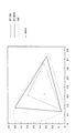
図4の右には、Y、U及びVという3つの成分軸を有するエンハンスメントレイヤの色空間CSEが示されている。部分空間CE1は、エンハンスメントレイヤの色空間CSE内で、直方体区画CB1に対応する部分を占める。カラーマッピングテーブルは、こうしたベースレイヤの各直方体区画に対応するエンハンスメントレイヤの部分空間を、4つの頂点を定義することによって特定する。そして、例えば直方体区画CB1に属する入力画素PB1に対応する予測画素PE1の画素値は、部分空間CE1の4つの頂点の画素値に基づく三角錐補間によって決定される。
The right of FIG. 4, Y, a color space CS E enhancement layer having a three-component axes that U and V are shown. The partial space C E1 occupies a portion corresponding to the rectangular parallelepiped section C B1 in the enhancement layer color space CS E. The color mapping table specifies the enhancement layer subspace corresponding to each rectangular parallelepiped of such a base layer by defining four vertices. For example, the pixel value of the prediction pixel P E1 corresponding to the input pixel P B1 belonging to the rectangular parallelepiped section C B1 is determined by triangular pyramid interpolation based on the pixel values of the four vertices of the partial space C E1 .
図5には、一例として、直方体区画CB1に対応する部分空間CE1の4つの頂点V11、V12、V13及びV14が示されている。これら頂点の位置を特定するために、典型的には、4つのパラメータR1、R2、R3及びR4が符号化され得る。例えば、パラメータR1は、Y軸方向での、ある特定の基準位置V10(例えば隣接区画の頂点位置)からの頂点V11のオフセットを特定する。パラメータR2は、V軸方向での頂点V11からの頂点V12のオフセットを特定する。パラメータR3は、U軸方向での頂点V12からの頂点V13のオフセットを特定する。パラメータR4は、Y軸方向でのある特定の基準位置V15からの頂点V14のオフセットを特定する。 FIG. 5 shows, as an example, four vertices V 11 , V 12 , V 13, and V 14 of the partial space C E1 corresponding to the rectangular parallelepiped section C B1 . To identify the positions of these vertices, typically four parameters R 1 , R 2 , R 3 and R 4 can be encoded. For example, the parameter R 1 specifies the offset of the vertex V 11 from a certain reference position V 10 (for example, the vertex position of the adjacent section) in the Y-axis direction. Parameters R 2 specifies the offset of the vertex V 12 from the vertex V 11 in the V-axis direction. Parameter R 3 specifies the offset of the vertex V 13 from the vertex V 12 in the U-axis direction. Parameters R 4 identifies some offset of the vertex V 14 from a particular reference position V 15 in the Y-axis direction.
表1〜表3は、非特許文献2に記載されている、カラーマッピングテーブルに関連するシンタックスを示している。表1に示したように、PPS(Picture Parameter Set)において、カラーマッピングテーブルを有効化するフラグcolour_mapping_enabled_flagが真(True)に設定される場合に、カラーマッピングテーブルを定義する関数colour_mapping_table()が呼び出される。
Tables 1 to 3 show syntax related to the color mapping table described in

表2に示した関数colour_mapping_table()のパラメータcm_octant_depth及びパラメータcm_y_part_num_log2は、それぞれ、3つの色成分についての分割の深さの上限値、及び輝度成分についての追加的な分割の深さに関連するパラメータである。パラメータcm_input_luma_bit_depth_minus8及びcm_input_chroma_bit_depth_deltaは、カラーマッピングテーブルの入力画素値のビット深度に関連するパラメータである。パラメータcm_output_luma_bit_depth_minus8及びcm_output_chroma_bit_depth_deltaは、カラーマッピングテーブルの出力画素値のビット深度に関連するパラメータである。パラメータcm_res_quant_bitsは、出力画素値の量子化に関連するパラメータである。関数colour_mapping_octants()は再帰関数であり、その詳細は表3に示されている。 The parameter cm_octant_depth and the parameter cm_y_part_num_log2 of the function colour_mapping_table () shown in Table 2 are parameters related to the upper limit value of the division depth for the three color components and the additional division depth for the luminance component, respectively. is there. Parameters cm_input_luma_bit_depth_minus8 and cm_input_chroma_bit_depth_delta are parameters related to the bit depth of the input pixel value of the color mapping table. The parameters cm_output_luma_bit_depth_minus8 and cm_output_chroma_bit_depth_delta are parameters related to the bit depth of the output pixel value of the color mapping table. The parameter cm_res_quant_bits is a parameter related to the quantization of the output pixel value. The function colour_mapping_octants () is a recursive function, the details of which are shown in Table 3.
表3に示した関数colour_mapping_octants()は、前半部(第2行〜第10行)及び後半部(第11行〜第21行)から構成される。前半部は、主にカラーマッピングテーブルの粒度を定義する粒度情報(第3行)と関数の再帰的な呼び出し(第8行〜第9行)とを含む。ここでの粒度情報は、ベースレイヤの色空間の分割を定義する分割フラグsplit_octant_flagのセットを含む。ある直方体区画がさらに分割される場合には、分割フラグは真を示す。分割フラグが真を示す場合、さらに当該区画を分割することにより形成される8個のサブ区画(オクタント)の各々について関数colour_mapping_octants()が再帰的に呼び出される。ある直方体区画がそれ以上分割されない場合には、分割フラグは偽を示す。分割フラグが偽を示す場合、シンタックスの後半部において、当該区画に対応する予測値情報が符号化される。ここでの予測値情報は、エンハンスメントレイヤの色空間の部分空間を、部分空間の4つの頂点に対応する変数vertexの繰り返しと共に、パラメータres_y、res_u及びres_vによって特定する The function colour_mapping_octants () shown in Table 3 is composed of a first half (2nd to 10th lines) and a second half (11th to 21st lines). The first half mainly includes granularity information (line 3) that defines the granularity of the color mapping table and recursive function calls (line 8 to line 9). The granularity information here includes a set of split flags split_octant_flag that defines the division of the color space of the base layer. When a certain rectangular parallelepiped section is further divided, the division flag indicates true. When the division flag indicates true, the function colour_mapping_octants () is recursively called for each of the eight sub-partitions (octants) formed by further dividing the section. When a certain rectangular parallelepiped section is not further divided, the division flag indicates false. When the division flag indicates false, prediction value information corresponding to the partition is encoded in the latter half of the syntax. The prediction value information here specifies the partial space of the enhancement layer color space by the parameters res_y, res_u, and res_v together with the repetition of the variable vertex corresponding to the four vertices of the partial space.
上述した粒度情報により特定されるベースレイヤの色空間の分割の粒度がより精細であるほど、ベースレイヤの色空間の区画数はより多くなる。上述した予測値情報は、ベースレイヤの色空間の区画の数(と頂点の数(=4)との積)だけ繰り返されるため、粒度の精細さによる予測精度の向上は、ルックアップテーブルを定義するために要する符号量の増加との間でトレードオフの関係にある。ここで、例えばダイナミックレンジスケーラビリティでは、輝度成分についての変換は必ずしも線型的ではないためにより精細な空間分割が望ましい一方で、色差成分についての変換はより単純な線形変換(即ち、より粗い空間分割に基づく線型内挿など)であってよい。しかし、既存の手法の上述したシンタックスは、エンハンスメントレイヤの3つの色成分を予測するために画一的な(即ち1通りの)分割の粒度しか定義することができない。結果的に、ある色成分についての最適な空間分割の粒度が、他の色成分にとっては粗すぎるか又は必要以上に精細すぎることがある。 The finer the granularity of the division of the base layer color space specified by the granularity information described above, the greater the number of divisions of the base layer color space. Since the prediction value information described above is repeated by the number of sections in the color space of the base layer (and the product of the number of vertices (= 4)), an improvement in prediction accuracy due to granularity definition defines a lookup table. There is a trade-off relationship with an increase in the amount of code required to do this. Here, for example, in dynamic range scalability, since the transformation for the luminance component is not necessarily linear, a finer spatial division is desirable, while the transformation for the chrominance component is a simpler linear transformation (i.e., a coarser spatial division). Based linear interpolation, etc.). However, the above-described syntax of the existing method can only define a uniform (ie, one way) granularity to predict the three color components of the enhancement layer. As a result, the optimal spatial partitioning granularity for one color component may be too coarse or too fine for other color components.
そこで、以下に説明する実施形態では、ルックアップテーブル方式のスケーラブル符号化技術において、色空間の分割の粒度をより柔軟に扱うことのできる仕組みが導入される。それら実施形態によれば、輝度成分のインターレイヤ予測のための第1のルックアップテーブルとは別に、色差成分の少なくとも一方のインターレイヤ予測のための、第1のルックアップテーブルとは粒度の異なる第2のルックアップテーブルを定義することが許容される。 Therefore, in the embodiment described below, a mechanism capable of more flexibly handling the granularity of color space division is introduced in the lookup table type scalable coding technique. According to these embodiments, apart from the first look-up table for the inter-layer prediction of the luminance component, the granularity is different from the first look-up table for the inter-layer prediction of at least one of the chrominance components. It is permissible to define a second lookup table.
[1−3.エンコーダの基本的な構成例]
図6は、スケーラブル符号化をサポートする、一実施形態に係る画像符号化装置10の概略的な構成を示すブロック図である。図6を参照すると、画像符号化装置10は、ベースレイヤ(BL)符号化部1a、エンハンスメントレイヤ(EL)符号化部1b、共通メモリ2及び多重化部3を備える。
[1-3. Basic encoder configuration example]
FIG. 6 is a block diagram illustrating a schematic configuration of an
BL符号化部1aは、ベースレイヤ画像を符号化し、ベースレイヤの符号化ストリームを生成する。EL符号化部1bは、エンハンスメントレイヤ画像を符号化し、エンハンスメントレイヤの符号化ストリームを生成する。共通メモリ2は、レイヤ間で共通的に利用される情報を記憶する。多重化部3は、BL符号化部1aにより生成されるベースレイヤの符号化ストリームと、EL符号化部1bにより生成される1つ以上のエンハンスメントレイヤの符号化ストリームとを多重化し、マルチレイヤの多重化ストリームを生成する。
The BL encoding unit 1a encodes a base layer image and generates a base layer encoded stream. The
[1−4.デコーダの基本的な構成例]
図7は、スケーラブル符号化をサポートする、一実施形態に係る画像復号装置60の概略的な構成を示すブロック図である。図7を参照すると、画像復号装置60は、逆多重化部5、ベースレイヤ(BL)復号部6a、エンハンスメントレイヤ(EL)復号部6b及び共通メモリ7を備える。
[1-4. Basic configuration example of decoder]
FIG. 7 is a block diagram illustrating a schematic configuration of an
逆多重化部5は、マルチレイヤの多重化ストリームをベースレイヤの符号化ストリーム及び1つ以上のエンハンスメントレイヤの符号化ストリームに逆多重化する。BL復号部6aは、ベースレイヤの符号化ストリームからベースレイヤ画像を復号する。EL復号部6bは、エンハンスメントレイヤの符号化ストリームからエンハンスメントレイヤ画像を復号する。共通メモリ7は、レイヤ間で共通的に利用される情報を記憶する。
The demultiplexer 5 demultiplexes the multi-layer multiplexed stream into a base layer encoded stream and one or more enhancement layer encoded streams. The
図6に例示した画像符号化装置10において、ベースレイヤの符号化のためのBL符号化部1aの構成と、エンハンスメントレイヤの符号化のためのEL符号化部1bの構成とは、互いに類似する。BL符号化部1aにより生成され又は取得されるいくつかのパラメータ及び画像は、共通メモリ2を用いてバッファリングされ、EL符号化部1bにより再利用され得る。次節では、そのようなEL符号化部1bの構成について詳細に説明する。
In the
同様に、図7に例示した画像復号装置60において、ベースレイヤの復号のためのBL復号部6aの構成と、エンハンスメントレイヤの復号のためのEL復号部6bの構成とは、互いに類似する。BL復号部6aにより生成され又は取得されるいくつかのパラメータ及び画像は、共通メモリ7を用いてバッファリングされ、EL復号部6bにより再利用され得る。さらに次の節では、そのようなEL復号部6bの構成について詳細に説明する。
Similarly, in the
<2.一実施形態に係るEL符号化部の構成例>
[2−1.各部の説明]
図8は、図6に示したEL符号化部1bの構成の一例を示すブロック図である。図8を参照すると、EL符号化部1bは、並び替えバッファ11、減算部13、直交変換部14、量子化部15、可逆符号化部16、蓄積バッファ17、レート制御部18、逆量子化部21、逆直交変換部22、加算部23、ループフィルタ24、フレームメモリ25、セレクタ26及び27、イントラ予測部30、インター予測部35、インターレイヤ予測部40並びにLUTバッファ45を備える。
<2. Configuration Example of EL Encoding Unit According to One Embodiment>
[2-1. Description of each part]
FIG. 8 is a block diagram showing an example of the configuration of the
並び替えバッファ11は、一連の画像データに含まれる画像を並び替える。並び替えバッファ11は、符号化処理に係るGOP(Group of Pictures)構造に応じて画像を並び替えた後、並び替え後の画像データを減算部13、イントラ予測部30、インター予測部35及びインターレイヤ予測部40へ出力する。
The
減算部13には、並び替えバッファ11から入力される画像データ、及び後に説明するイントラ予測部30又はインター予測部35から入力される予測画像データが供給される。減算部13は、並び替えバッファ11から入力される画像データと予測画像データとの差分である予測誤差データを計算し、計算した予測誤差データを直交変換部14へ出力する。
The
直交変換部14は、減算部13から入力される予測誤差データについて直交変換を行う。直交変換部14により実行される直交変換は、例えば、離散コサイン変換(Discrete Cosine Transform:DCT)又はカルーネン・レーベ変換などであってよい。HEVCにおいて、直交変換は、TU(変換単位:Transform Unit)と呼ばれるブロックごとに実行される。TUは、CU(符号化単位:Coding Unit)を分割することにより形成されるブロックである。直交変換部14は、直交変換処理により取得される変換係数データを量子化部15へ出力する。
The
量子化部15には、直交変換部14から入力される変換係数データ、及び後に説明するレート制御部18からのレート制御信号が供給される。量子化部15は、レート制御信号に従って決定される量子化ステップで変換係数データを量子化する。量子化部15は、量子化後の変換係数データ(以下、量子化データという)を可逆符号化部16及び逆量子化部21へ出力する。
The
可逆符号化部16は、量子化部15から入力される量子化データについて可逆符号化処理を行うことにより、エンハンスメントレイヤの符号化ストリームを生成する。また、可逆符号化部16は、符号化ストリームを復号する際に参照される様々なパラメータを符号化して、符号化されたパラメータを符号化ストリームのヘッダ領域に挿入する。可逆符号化部16により符号化されるパラメータは、後に説明するイントラ予測に関する情報、インター予測に関する情報、及びインターレイヤ予測に関する情報を含み得る。そして、可逆符号化部16は、生成した符号化ストリームを蓄積バッファ17へ出力する。
The
蓄積バッファ17は、可逆符号化部16から入力される符号化ストリームを半導体メモリなどの記憶媒体を用いて一時的に蓄積する。そして、蓄積バッファ17は、蓄積した符号化ストリームを、伝送路の帯域に応じたレートで、図示しない伝送部(例えば、通信インタフェース又は周辺機器との接続インタフェースなど)へ出力する。
The
レート制御部18は、蓄積バッファ17の空き容量を監視する。そして、レート制御部18は、蓄積バッファ17の空き容量に応じてレート制御信号を生成し、生成したレート制御信号を量子化部15へ出力する。例えば、レート制御部18は、蓄積バッファ17の空き容量が少ない時には、量子化データのビットレートを低下させるためのレート制御信号を生成する。また、例えば、レート制御部18は、蓄積バッファ17の空き容量が十分大きい時には、量子化データのビットレートを高めるためのレート制御信号を生成する。
The
逆量子化部21、逆直交変換部22及び加算部23は、ローカルデコーダを構成する。逆量子化部21は、量子化部15により使用されたものと同じ量子化ステップで、エンハンスメントレイヤの量子化データを逆量子化し、変換係数データを復元する。そして、逆量子化部21は、復元した変換係数データを逆直交変換部22へ出力する。
The
逆直交変換部22は、逆量子化部21から入力される変換係数データについて逆直交変換処理を行うことにより、予測誤差データを復元する。直交変換と同様、逆直交変換は、TUごとに実行される。そして、逆直交変換部22は、復元した予測誤差データを加算部23へ出力する。
The inverse
加算部23は、逆直交変換部22から入力される復元された予測誤差データとイントラ予測部30又はインター予測部35から入力される予測画像データとを加算することにより、復号画像データ(エンハンスメントレイヤのリコンストラクト画像)を生成する。そして、加算部23は、生成した復号画像データをループフィルタ24及びフレームメモリ25へ出力する。
The adding
ループフィルタ24は、画質の向上を目的とするフィルタ群を含む。デブロックフィルタ(DF)は、画像の符号化時に生じるブロック歪みを軽減するフィルタである。サンプル適応オフセット(SAO)フィルタは、各画素値に適応的に決定されるオフセット値を加えるフィルタである。ループフィルタ24は、加算部23から入力される復号画像データをフィルタリングし、フィルタリング後の復号画像データをフレームメモリ25へ出力する。
The
フレームメモリ25は、加算部23から入力されるエンハンスメントレイヤの復号画像データ、ループフィルタ24から入力されるエンハンスメントレイヤのフィルタリング後の復号画像データ、及びインターレイヤ予測部40から入力されるベースレイヤの参照画像データを記憶媒体を用いて記憶する。
The
セレクタ26は、イントラ予測のために使用されるフィルタリング前の復号画像データをフレームメモリ25から読み出し、読み出した復号画像データを参照画像データとしてイントラ予測部30に供給する。また、セレクタ26は、インター予測のために使用されるフィルタリング後の復号画像データをフレームメモリ25から読み出し、読み出した復号画像データを参照画像データとしてインター予測部35に供給する。さらに、イントラ予測部30又はインター予測部35においてインターレイヤ予測に基づく画像が利用される場合、セレクタ26は、インターレイヤ予測部40により生成される参照画像データをイントラ予測部30又はインター予測部35へ供給する。
The
セレクタ27は、イントラ予測モードにおいて、イントラ予測部30から出力されるイントラ予測の結果としての予測画像データを減算部13へ出力すると共に、イントラ予測に関する情報を可逆符号化部16へ出力する。また、セレクタ27は、インター予測モードにおいて、インター予測部35から出力されるインター予測の結果としての予測画像データを減算部13へ出力すると共に、インター予測に関する情報を可逆符号化部16へ出力する。セレクタ27は、イントラ予測モードとインター予測モードとを、コスト関数値の大きさに応じて切り替える。
In the intra prediction mode, the
イントラ予測部30は、エンハンスメントレイヤの原画像データ及び復号画像データに基づいて、HEVCのPU(予測単位:Prediction Unit)ごとにイントラ予測処理を行う。例えば、イントラ予測部30は、予測モードセット内の各候補モードによる予測結果を所定のコスト関数を用いて評価する。次に、イントラ予測部30は、コスト関数値が最小となる予測モード、即ち圧縮率が最も高くなる予測モードを、最適な予測モードとして選択する。また、イントラ予測部30は、当該最適な予測モードに従ってエンハンスメントレイヤの予測画像データを生成する。イントラ予測部30は、エンハンスメントレイヤにおける予測モードセットに、インターレイヤ予測に基づく画像を利用するイントラBL予測又はイントラ残差予測を含めてもよい。イントラ予測部30は、選択した最適な予測モードを表す予測モード情報を含むイントラ予測に関する情報、コスト関数値、及び予測画像データを、セレクタ27へ出力する。
The
インター予測部35は、エンハンスメントレイヤの原画像データ及び復号画像データに基づいて、HEVCのPUごとにインター予測処理を行う。例えば、インター予測部35は、予測モードセット内の各候補モードによる予測結果を所定のコスト関数を用いて評価する。次に、インター予測部35は、コスト関数値が最小となる予測モード、即ち圧縮率が最も高くなる予測モードを、最適な予測モードとして選択する。また、インター予測部35は、当該最適な予測モードに従ってエンハンスメントレイヤの予測画像データを生成する。インター予測部35は、エンハンスメントレイヤにおける予測モードセットに、インターレイヤ予測に基づく画像を利用するインター残差予測を含めてもよい。インター予測部35は、選択した最適な予測モードを表す予測モード情報と動き情報とを含むインター予測に関する情報、コスト関数値、及び予測画像データを、セレクタ27へ出力する。
The
インターレイヤ予測部40は、共通メモリ2によりバッファリングされるベースレイヤの画像(復号画像又は予測誤差画像)を、ベースレイヤとエンハンスメントレイヤとの間の解像度比に従ってアップサンプリングする。また、インターレイヤ予測部40は、ベースレイヤの画像とは異なる画素属性をエンハンスメントレイヤの画像が有する場合に、アップサンプリングしたベースレイヤの画素の各々の画素値を、ルックアップテーブル(LUT)を用いてエンハンスメントレイヤの予測画素値に変換する。ここでの画素属性は、色域、ビット深度及びダイナミックレンジのうち少なくとも1つを含む。また、インターレイヤ予測部40は、インターレイヤ予測のために使用すべきルックアップテーブルを定義するルックアップテーブル情報を生成する。ルックアップテーブル情報は、主に粒度情報と予測値情報とを含む。インターレイヤ予測部40により生成されるルックアップテーブル情報は、可逆符号化部16へ出力され、可逆符号化部16により符号化される。
The inter
本実施形態において、インターレイヤ予測部40は、輝度成分(Y)用のLUT(LUT_Y)を用いてエンハンスメントレイヤの輝度成分の予測値を取得し、第1色差成分(U)用のLUT(LUT_U)を用いてエンハンスメントレイヤの第1色差成分の予測値を取得する。さらに、インターレイヤ予測部40は、第2色差成分(V)用のLUT(LUT_V)を用いてエンハンスメントレイヤの第2色差成分の予測値を取得してもよい。LUT_Y、LUT_U及びLUT_Vの空間分割の粒度は、それぞれ異なるように設定可能である(粒度が異なることは必須ではなく、符号化コストが最小化される場合には結果的に粒度は等しくなってもよい)。空間分割の粒度は、画素属性の種類、システムの要件又はユーザによる事前の設定などに依存して、予め設定されてもよい。なお、第1色差成分及び第2色差成分のインターレイヤ予測のために、1つのLUTが共用されてもよい。インターレイヤ予測部40により2つ以上のルックアップテーブルの使用を通じて生成される予測画像は、フレームメモリ25に格納され、イントラ予測部30又はインター予測部35により参照画像として使用され得る。
In the present embodiment, the
LUTバッファ45は、インターレイヤ予測部40により使用される2つ以上のルックアップテーブル(LUT_Y、LUT_U及びLUT_Vのうちの2つ以上)をバッファリングするバッファである。各ルックアップテーブルは、ベースレイヤの輝度成分(Y)、第1色差成分(U)及び第2色差成分(V)の組合せと当該組合せに対応するエンハンスメントレイヤの予測画素値とをマッピングする。
The
[2−2.シンタックス例]
本実施形態において、インターレイヤ予測部40により生成され可逆符号化部16により符号化されるルックアップテーブル情報は、少なくとも、LUT_Y用のテーブル情報とLUT_U用のテーブル情報とを含む。さらに、ルックアップテーブル情報は、LUT_V用のテーブル情報を含んでもよい。各テーブルのテーブル情報は、主に、ベースレイヤの色空間の分割を定義するフラグのセットを含む粒度情報と、分割により形成される複数の直方体区画の各々に対応する予測値情報と、を包含する。
[2-2. Syntax example]
In the present embodiment, the lookup table information generated by the
表4〜表6は、本実施形態に係るルックアップテーブル情報のシンタックスの一例を示している。表4に示したように、本実施形態では、PPSにおいて、カラーマッピングテーブルを有効化するフラグcolour_mapping_enabled_flagが真(True)に設定される場合に、ルックアップテーブルを定義する関数colour_mapping_table(component)が、定義を必要とする色成分ごとに呼び出される。関数colour_mapping_table(component)の引数componentは色成分の識別子であり、例えば“Y”、“U”又は“V”のいずれかであってよい。下表の例では、Y成分、U成分及びV成分のためのルックアップテーブルを別々に定義するために、関数colour_mapping_table(component)が3回呼び出されている。 Tables 4 to 6 show an example of syntax of lookup table information according to the present embodiment. As shown in Table 4, in this embodiment, in the PPS, when the flag colour_mapping_enabled_flag that enables the color mapping table is set to true, the function colour_mapping_table (component) that defines the lookup table is Called for each color component that needs to be defined. The argument component of the function colour_mapping_table (component) is an identifier of a color component, and may be, for example, “Y”, “U”, or “V”. In the example of the table below, the function colour_mapping_table (component) is called three times in order to separately define the look-up tables for the Y component, U component and V component.
表5に示した関数colour_mapping_table(component)に含まれるパラメータの役割は、表2を参照しながら説明した同じ名称のパラメータの役割と同様であってよい。関数colour_mapping_octants()は再帰関数である。表5の再帰関数colour_mapping_octants()は、表2に示した同じ名称の関数と比較して、追加的な引数“component”を有する。この追加的な引数は、関数colour_mapping_table()へ入力される色成分の識別子に等しい。 The role of the parameter included in the function colour_mapping_table (component) shown in Table 5 may be the same as the role of the parameter of the same name described with reference to Table 2. The function colour_mapping_octants () is a recursive function. The recursive function colour_mapping_octants () in Table 5 has an additional argument “component” compared to the function of the same name shown in Table 2. This additional argument is equal to the identifier of the color component input to the function colour_mapping_table ().
表6に示した関数colour_mapping_octants()は、粒度情報を含む前半部(第2行〜第10行)、及び予測値情報を含む後半部(第11行〜第19行)から構成される。粒度情報は、再帰的に指定される、ベースレイヤの色空間の分割を定義する分割フラグsplit_octant_flagのセットを含む。表3に示したシンタックスとの粒度情報における相違は、関数colour_mapping_table(component)が色成分ごとに別々に呼び出される(表4参照)結果として、表6の分割フラグのセット(即ち、粒度情報)もまた色成分ごとに別々に定義される点である。予測値情報は、ある直方体区画がそれ以上分割されない場合(即ち、対応する分割フラグが偽を示す場合)に、当該直方体区画に対応するエンハンスメントレイヤの色空間の部分空間を、当該部分空間の頂点位置を示すことにより特定する。表3に示したシンタックスとの予測値情報における相違は、変数vertexの1回のループの中に収容される頂点位置のパラメータが、1つのパラメータres_component(文字列“component”は、色成分の識別子“Y”、“U”又は“V”に置換される)に集約される点である。 The function colour_mapping_octants () shown in Table 6 includes a first half (second to tenth lines) including granularity information and a second half (11th to 19th lines) including predicted value information. The granularity information includes a set of split flags split_octant_flag that define recursively splitting the color space of the base layer. The difference in granularity information from the syntax shown in Table 3 is that the function colour_mapping_table (component) is called separately for each color component (see Table 4). As a result, the set of division flags in Table 6 (ie, granularity information) Is also defined separately for each color component. The predicted value information indicates that when a certain rectangular parallelepiped section is not further divided (that is, when the corresponding division flag indicates false), the color space subspace of the enhancement layer corresponding to the rectangular parallelepiped section is expressed as the vertex of the subspace. It is specified by indicating the position. The difference in the predicted value information from the syntax shown in Table 3 is that the parameter of the vertex position accommodated in one loop of the variable vertex is one parameter res_component (the character string “component” is the color component (Replaced by the identifier “Y”, “U” or “V”).
表4〜表6に示したシンタックスは一例に過ぎず、一部のパラメータが省略され又は他の追加的なパラメータが採用されてもよい。例えば、インターレイヤ予測部40は、LUT_Y用の粒度情報とは別にLUT_U用(又はLUT_V用)の粒度情報が符号化されるか否かを示すフラグ、又はLUT_U用の粒度情報とは別にLUT_V用の粒度情報が符号化されるか否かを示すフラグを、符号化される追加的なパラメータとして生成してもよい。空間分割の粒度を色成分の間で別々に定義する必要の無い場合には、これらフラグは、偽を示し得る。
The syntaxes shown in Tables 4 to 6 are merely examples, and some parameters may be omitted or other additional parameters may be employed. For example, the
<3.一実施形態に係る符号化時の処理の流れ>
[3−1.概略的な流れ]
図9は、一実施形態に係る符号化時の概略的な処理の流れの一例を示すフローチャートである。なお、説明の簡明さのために、本開示に係る技術に直接的に関連しない処理ステップは、図から省略されている。
<3. Flow of processing during encoding according to one embodiment>
[3-1. Schematic flow]
FIG. 9 is a flowchart illustrating an example of a schematic processing flow at the time of encoding according to an embodiment. Note that processing steps that are not directly related to the technology according to the present disclosure are omitted from the drawing for the sake of simplicity of explanation.
図9を参照すると、まず、BL符号化部1aは、ベースレイヤの符号化処理を実行し、ベースレイヤの符号化ストリームを生成する(ステップS11)。 Referring to FIG. 9, first, the BL encoding unit 1a performs base layer encoding processing to generate a base layer encoded stream (step S11).
共通メモリ2は、ベースレイヤの符号化処理において生成されるベースレイヤの画像(復号画像及び予測誤差画像の一方又は双方)及びレイヤ間で再利用されるパラメータをバッファリングする(ステップS12)。レイヤ間で再利用されるパラメータは、例えば、解像度情報及び画素属性を識別する識別情報(例えば、色域情報、ダイナミックレンジ情報及びビット深度情報のうちの1つ以上)を含み得る。
The
次に、EL符号化部1bは、エンハンスメントレイヤの符号化処理を実行し、エンハンスメントレイヤの符号化ストリームを生成する(ステップS13)。ここで実行されるエンハンスメントレイヤの符号化処理において、インターレイヤ予測部40は、共通メモリ2によりバッファリングされるベースレイヤの画像を、空間分割の粒度の相違し得る2つ以上のルックアップテーブルを用いて、予測画像に変換する。そして、変換後の予測画像は、エンハンスメントレイヤにおいて参照画像として使用され得る。
Next, the
次に、多重化部3は、BL符号化部1aにより生成されるベースレイヤの符号化ストリームと、EL符号化部1bにより生成されるエンハンスメントレイヤの符号化ストリームとを多重化し、マルチレイヤの多重化ストリームを生成する(ステップS14)。
Next, the
[3−2.空間分割処理]
図10は、符号化時の空間分割処理の流れの一例を示すフローチャートである。図10を参照すると、インターレイヤ予測部40は、まず、制御変数を初期化する。例えば、最小のコスト値を保持する変数Rminの値及び分割の深さは共にゼロへ初期化され得る(再帰の初期状態は、“分割なし”に相当する)。
[3-2. Spatial partition processing]
FIG. 10 is a flowchart illustrating an example of the flow of space division processing during encoding. Referring to FIG. 10, the
次に、インターレイヤ予測部40は、“分割なし”の場合のベースレイヤの区画(ベースレイヤの色空間全体を占める1つの区画)に対応するエンハンスメントレイヤの部分空間を決定する(ステップS13)。例えば、インターレイヤ予測部40は、エンハンスメントレイヤの原画像と(必要に応じてアップアンプリングされた)ベースレイヤのリコンストラクト画像との相関に基づいて、エンハンスメントレイヤの対応する部分空間を決定し得る。
Next, the
次に、インターレイヤ予測部40は、“分割なし”の場合の符号化コスト(R)を、予測誤差及び想定される符号量に基づいて計算し、その計算結果で最小コストを更新する(Rmin←R)(ステップS15)。
Next, the
次のステップS19からステップS29までの処理は、分割可能な区画が存在しないと判定されるまで繰り返される(ステップS17)。その繰り返しの中で、インターレイヤ予測部40は、まず、いずれかの注目区画を分割する(ステップS19)。ここでの分割は、オクタント分割(2×2×2個のサブ区画への分割)又はY成分軸のみの追加的な分割であってよい。次に、インターレイヤ予測部40は、分割によって形成されるサブ区画の各々に対応するエンハンスメントレイヤの部分空間を決定する(ステップS21)。次に、インターレイヤ予測部40は、ステップS19における分割が反映された符号化コスト(R)を、予測誤差及び想定される符号量に基づいて計算する(ステップS23)。そして、インターレイヤ予測部40は、計算された符号化コストをその時点の最小コストと比較する(ステップS25)。インターレイヤ予測部40は、計算された符号化コストが最小コストよりも低い場合には、計算された符号化コストで最小コストを更新し(Rmin←R)、注目区画の分割フラグを真に設定する(ステップS27)。一方、インターレイヤ予測部40は、計算された符号化コストがその時点の最小コストよりも低くない場合には、最小コストを更新することなく、注目区画の分割フラグを偽に設定する(ステップS29)。
The processing from the next step S19 to step S29 is repeated until it is determined that there is no partitionable division (step S17). In the repetition, the
このような処理が、分割の深さが上限に達し、又は最小コストが更新されなくなるまで、再帰的に繰り返される。その結果、分割フラグのセットを含む1つのテーブルについての粒度情報が生成される。また、分割後の各直方体区画に対応するエンハンスメントレイヤの部分空間が決定される。 Such a process is recursively repeated until the depth of division reaches the upper limit or the minimum cost is not updated. As a result, granularity information for one table including the set of division flags is generated. In addition, a partial space of the enhancement layer corresponding to each divided rectangular parallelepiped section is determined.
[3−3.テーブル情報符号化処理]
(1)既存の手法
図11は、既存の手法に従ったテーブル情報符号化処理の流れの一例を示すフローチャートである。図11を参照すると、まず、エンハンスメントレイヤの輝度成分(Y)、第1色差成分(U)及び第2色差成分(V)について共通的に、図10に例示したような空間分割処理が一度実行される(ステップS110)。
[3-3. Table information encoding process]
(1) Existing Method FIG. 11 is a flowchart illustrating an example of the flow of table information encoding processing according to an existing method. Referring to FIG. 11, first, the space division process illustrated in FIG. 10 is executed once for the luminance component (Y), the first color difference component (U), and the second color difference component (V) of the enhancement layer. (Step S110).
次に、空間分割処理の結果に基づいて、エンハンスメントレイヤの3つの色成分について共通の粒度情報が符号化される(ステップS120)。また、空間分割処理において決定されたエンハンスメントレイヤの輝度成分用の予測値情報、第1色差成分用の予測値情報及び第2色差成分用の予測値情報がそれぞれ符号化される(ステップS122、S124及びS126)。これら粒度情報及び予測値情報のシンタックスは、上の表1〜表3に示したように整形され得る。 Next, common granularity information is encoded for the three color components of the enhancement layer based on the result of the space division processing (step S120). Further, the prediction value information for the luminance component of the enhancement layer, the prediction value information for the first chrominance component, and the prediction value information for the second chrominance component determined in the space division processing are respectively encoded (steps S122 and S124). And S126). The syntaxes of the granularity information and the predicted value information can be shaped as shown in Tables 1 to 3 above.
(2)新たな手法
図12は、上述した実施形態に係る新たな手法に従ったテーブル情報符号化処理の流れの一例を示すフローチャートである。
(2) New Method FIG. 12 is a flowchart illustrating an example of the flow of table information encoding processing according to the new method according to the above-described embodiment.
図12を参照すると、まず、インターレイヤ予測部40は、エンハンスメントレイヤの輝度成分(Y)用のルックアップテーブル(LUT_Y)の空間分割の粒度を決定するための空間分割処理を実行する(ステップS112)。また、インターレイヤ予測部40は、エンハンスメントレイヤの第1色差成分(U)用のルックアップテーブル(LUT_U)の空間分割の粒度を決定するための空間分割処理を実行する(ステップS114)。また、インターレイヤ予測部40は、エンハンスメントレイヤの第2色差成分(V)用のルックアップテーブル(LUT_V)の空間分割の粒度を決定するための空間分割処理を実行する(ステップS116)。
Referring to FIG. 12, first, the inter
次に、可逆符号化部16は、ステップS112における空間分割処理の結果に基づいて、LUT_Yのための第1の粒度情報を符号化し(ステップS130)、及びLUT_Yのための第1の予測値情報を符号化する(ステップS135)。また、可逆符号化部16は、ステップS114における空間分割処理の結果に基づいて、LUT_Uのための第2の粒度情報を符号化し(ステップS140)、及びLUT_Uのための第2の予測値情報を符号化する(ステップS145)。また、可逆符号化部16は、ステップS116における空間分割処理の結果に基づいて、LUT_Vのための第3の粒度情報を符号化し(ステップS150)、及びLUT_Vのための第3の予測値情報を符号化する(ステップS155)。
Next, the
なお、ルックアップテーブルを他の色成分と共用する色成分については、当該色成分に固有のルックアップテーブル情報の符号化は省略されてよい。また、ルックアップテーブルが共用されるか否かを示す追加的なパラメータが符号化されてもよい。 For color components that share the lookup table with other color components, encoding of lookup table information unique to the color component may be omitted. Further, an additional parameter indicating whether or not the lookup table is shared may be encoded.
<4.一実施形態に係るEL復号部の構成例>
図13は、図7に示したEL復号部6bの構成の一例を示すブロック図である。図13を参照すると、EL復号部6bは、蓄積バッファ61、可逆復号部62、逆量子化部63、逆直交変換部64、加算部65、ループフィルタ66、並び替えバッファ67、D/A(Digital to Analogue)変換部68、フレームメモリ69、セレクタ70及び71、イントラ予測部80、インター予測部85、インターレイヤ予測部90並びにLUTバッファ95を備える。
<4. Configuration Example of EL Decoding Unit According to One Embodiment>
FIG. 13 is a block diagram showing an example of the configuration of the
蓄積バッファ61は、逆多重化部5から入力されるエンハンスメントレイヤの符号化ストリームを記憶媒体を用いて一時的に蓄積する。
The
可逆復号部62は、蓄積バッファ61から入力されるエンハンスメントレイヤの符号化ストリームから、符号化の際に使用された符号化方式に従ってエンハンスメントレイヤの量子化データを復号する。また、可逆復号部62は、符号化ストリームのヘッダ領域に挿入されている情報を復号する。可逆復号部62により復号される情報は、例えば、イントラ予測に関する情報、インター予測に関する情報、及びインターレイヤ予測に関する情報を含み得る。可逆復号部62は、量子化データを逆量子化部63へ出力する。また、可逆復号部62は、イントラ予測に関する情報をイントラ予測部80へ出力する。また、可逆復号部62は、インター予測に関する情報をインター予測部85へ出力する。また、可逆復号部62は、粒度の異なる2つ以上のルックアップテーブルを定義し得るルックアップテーブル情報を含むインターレイヤ予測に関する情報を、インターレイヤ予測部90へ出力する。
The
逆量子化部63は、可逆復号部62から入力される量子化データを、符号化の際に使用されたものと同じ量子化ステップで逆量子化し、エンハンスメントレイヤの変換係数データを復元する。逆量子化部63は、復元した変換係数データを逆直交変換部64へ出力する。
The
逆直交変換部64は、符号化の際に使用された直交変換方式に従い、逆量子化部63から入力される変換係数データについて逆直交変換を行うことにより、予測誤差データを生成する。逆直交変換部64は、生成した予測誤差データを加算部65へ出力する。
The inverse
加算部65は、逆直交変換部64から入力される予測誤差データと、セレクタ71から入力される予測画像データとを加算することにより、復号画像データを生成する。そして、加算部65は、生成した復号画像データをループフィルタ66及びフレームメモリ69へ出力する。
The adding
ループフィルタ66は、EL符号化部1bのループフィルタ24と同様、ブロック歪みを軽減するデブロックフィルタ及び各画素値にオフセット値を加えるサンプル適応オフセットフィルタを含む。ループフィルタ66は、加算部65から入力される復号画像データをフィルタリングし、フィルタリング後の復号画像データを並び替えバッファ67及びフレームメモリ69へ出力する。
Similarly to the
並び替えバッファ67は、ループフィルタ66から入力される画像を並び替えることにより、時系列の一連の画像データを生成する。そして、並び替えバッファ67は、生成した画像データをD/A変換部68へ出力する。
The
D/A変換部68は、並び替えバッファ67から入力されるデジタル形式の画像データをアナログ形式の画像信号に変換する。そして、D/A変換部68は、例えば、画像復号装置60と接続されるディスプレイ(図示せず)にアナログ画像信号を出力することにより、エンハンスメントレイヤの画像を表示させる。
The D /
フレームメモリ69は、加算部65から入力されるフィルタリング前の復号画像データ、ループフィルタ66から入力されるフィルタリング後の復号画像データ、及びインターレイヤ予測部90により生成される参照画像データを記憶媒体を用いて記憶する。
The
セレクタ70は、可逆復号部62により取得されるモード情報に応じて、画像内のブロックごとに、フレームメモリ69からの画像データの出力先をイントラ予測部80とインター予測部85との間で切り替える。例えば、セレクタ70は、イントラ予測モードが指定された場合には、フレームメモリ69から供給されるフィルタリング前の復号画像データを参照画像データとしてイントラ予測部80へ出力する。また、セレクタ70は、インター予測モードが指定された場合には、フィルタリング後の復号画像データを参照画像データとしてインター予測部85へ出力する。さらに、イントラ予測部80又はインター予測部85においてインターレイヤ予測に基づく画像が利用される場合、セレクタ70は、インターレイヤ予測部40により生成される参照画像データをイントラ予測部80又はインター予測部85へ供給する。
The
セレクタ71は、可逆復号部62により取得されるモード情報に応じて、加算部65へ供給すべき予測画像データの出力元をイントラ予測部80とインター予測部85との間で切り替える。例えば、セレクタ71は、イントラ予測モードが指定された場合には、イントラ予測部80から出力される予測画像データを加算部65へ供給する。また、セレクタ71は、インター予測モードが指定された場合には、インター予測部85から出力される予測画像データを加算部65へ供給する。
The
イントラ予測部80は、可逆復号部62から入力されるイントラ予測に関する情報とフレームメモリ69からの参照画像データとに基づいてエンハンスメントレイヤのイントラ予測処理を行い、予測画像データを生成する。イントラ予測処理は、PUごとに実行される。イントラ予測部80は、イントラ予測モードとしてイントラBL予測又はイントラ残差予測が指定された場合には、インターレイヤ予測部90により生成された画像を参照画像として使用する。イントラ予測部80は、生成したエンハンスメントレイヤの予測画像データをセレクタ71へ出力する。
The
インター予測部85は、可逆復号部62から入力されるインター予測に関する情報とフレームメモリ69からの参照画像データとに基づいてエンハンスメントレイヤのインター予測処理(動き補償処理)を行い、予測画像データを生成する。インター予測処理は、PUごとに実行される。インター予測部85は、インター予測モードとしてインター残差予測が指定された場合には、インターレイヤ予測部90により生成された画像を参照画像として使用する。インター予測部85は、生成したエンハンスメントレイヤの予測画像データをセレクタ71へ出力する。
The
インターレイヤ予測部90は、共通メモリ7によりバッファリングされるベースレイヤの画像(復号画像又は予測誤差画像)を、ベースレイヤとエンハンスメントレイヤとの間の解像度比に従ってアップサンプリングする。また、インターレイヤ予測部90は、ベースレイヤの画像とは異なる画素属性をエンハンスメントレイヤの画像が有する場合に、アップサンプリングしたベースレイヤの画素の各々の画素値を、ルックアップテーブル(LUT)を用いてエンハンスメントレイヤの予測画素値に変換する。ここでの画素属性は、色域、ビット深度及びダイナミックレンジのうち少なくとも1つを含む。インターレイヤ予測部90は、可逆復号部62から入力されるインターレイヤ予測に関する情報に基づいて、インターレイヤ予測のために使用すべきルックアップテーブルを再構築する。本実施形態において、インターレイヤ予測に関する情報は、上述したように、異なる色成分の予測値を取得するための、粒度の異なる2つ以上のルックアップテーブルを定義し得るルックアップテーブル情報を含む。
The
例えば、第1のルックアップテーブル情報は、輝度成分(Y)用のLUT(LUT_Y)の粒度を定義する粒度情報と共に、LUT_Yの各直方体区画に対応する予測値情報を含む。第2のルックアップテーブル情報は、第1色差成分(U)用のLUT(LUT_U)の粒度を定義する粒度情報と共に、LUT_Uの各直方体区画に対応する予測値情報を含む。これらルックアップテーブル情報のシンタックスは、例えば表4〜表6に示した通りであってよい。但し、一部のパラメータが当該シンタックスから省略されてもよく、又は他の追加的なパラメータが採用されてもよい。第2のルックアップテーブル情報は、LUT_U用の粒度情報がLUT_Y用の粒度情報とは別に符号化されていることを示すパラメータが復号された場合にのみ復号されてもよい。さらに、第2色差成分(V)用のLUT(LUT_V)の粒度を定義する粒度情報と共にLUT_Vの各直方体区画に対応する予測値情報を含む第3のルックアップテーブル情報もまた復号され得る。第3のルックアップテーブル情報は、LUT_V用の粒度情報がLUT_U用の粒度情報とは別に符号化されていることを示すパラメータが復号された場合にのみ復号されてもよい。 For example, the first look-up table information includes prediction value information corresponding to each rectangular parallelepiped section of the LUT_Y, together with the granularity information that defines the granularity of the LUT (LUT_Y) for the luminance component (Y). The second look-up table information includes prediction value information corresponding to each rectangular parallelepiped partition of the LUT_U, together with granularity information that defines the granularity of the LUT (LUT_U) for the first color difference component (U). The syntax of these lookup table information may be as shown in Tables 4 to 6, for example. However, some parameters may be omitted from the syntax, or other additional parameters may be employed. The second lookup table information may be decoded only when a parameter indicating that the granularity information for LUT_U is encoded separately from the granularity information for LUT_Y is decoded. Furthermore, third look-up table information including prediction value information corresponding to each rectangular parallelepiped partition of LUT_V can be decoded together with granularity information defining the granularity of the LUT (LUT_V) for the second color difference component (V). The third lookup table information may be decoded only when a parameter indicating that the granularity information for LUT_V is encoded separately from the granularity information for LUT_U is decoded.
インターレイヤ予測部90は、LUT_Yを用いてエンハンスメントレイヤの輝度成分の予測値を、LUT_Uを用いてエンハンスメントレイヤの第1色差成分の予測値を、LUT_Vを用いてエンハンスメントレイヤの第2色差成分の予測値をそれぞれ取得し得る。これらルックアップテーブルの空間分割の粒度を定義する粒度情報は、別個に復号される。これは、それぞれの空間分割の粒度が互いに異なるように定義可能であることを意味する。インターレイヤ予測部90により2つ以上のルックアップテーブルの使用を通じて生成される予測画像は、フレームメモリ69に格納され、イントラ予測部80又はインター予測部85により参照画像として使用され得る。
The
LUTバッファ95は、インターレイヤ予測部90により使用される2つ以上のルックアップテーブル(LUT_Y、LUT_U及びLUT_Vのうちの2つ以上)をバッファリングするバッファである。各ルックアップテーブルは、ベースレイヤの輝度成分(Y)、第1色差成分(U)及び第2色差成分(V)の組合せと当該組合せに対応するエンハンスメントレイヤの予測画素値とをマッピングする。
The
<5.一実施形態に係る復号時の処理の流れ>
[5−1.概略的な流れ]
図14は、一実施形態に係る復号時の概略的な処理の流れの一例を示すフローチャートである。なお、説明の簡明さのために、本開示に係る技術に直接的に関連しない処理ステップは、図から省略されている。
<5. Flow of processing at the time of decoding according to an embodiment>
[5-1. Schematic flow]
FIG. 14 is a flowchart illustrating an example of a schematic processing flow at the time of decoding according to an embodiment. Note that processing steps that are not directly related to the technology according to the present disclosure are omitted from the drawing for the sake of simplicity of explanation.
図14を参照すると、まず、逆多重化部5は、マルチレイヤの多重化ストリームをベースレイヤの符号化ストリーム及びエンハンスメントレイヤの符号化ストリームに逆多重化する(ステップS60)。 Referring to FIG. 14, first, the demultiplexer 5 demultiplexes the multi-layer multiplexed stream into the base layer encoded stream and the enhancement layer encoded stream (step S60).
次に、BL復号部6aは、ベースレイヤの復号処理を実行し、ベースレイヤの符号化ストリームからベースレイヤ画像を再構築する(ステップS61)。
Next, the
共通メモリ7は、ベースレイヤの復号処理において生成されるベースレイヤの画像(復号画像及び予測誤差画像の一方又は双方)及びレイヤ間で再利用されるパラメータをバッファリングする(ステップS62)。レイヤ間で再利用されるパラメータは、例えば、解像度情報及び画素属性を識別する識別情報(例えば、色域情報、ダイナミックレンジ情報及びビット深度情報のうちの1つ以上)を含み得る。 The common memory 7 buffers the base layer image (one or both of the decoded image and the prediction error image) generated in the base layer decoding process and the parameters reused between the layers (step S62). Parameters reused between layers may include, for example, resolution information and identification information that identifies pixel attributes (eg, one or more of color gamut information, dynamic range information, and bit depth information).
次に、EL復号部6bは、エンハンスメントレイヤの復号処理を実行し、エンハンスメントレイヤ画像を再構築する(ステップS63)。ここで実行されるエンハンスメントレイヤの復号処理において、インターレイヤ予測部90は、共通メモリ7によりバッファリングされるベースレイヤの画像を、空間分割の粒度の相違し得る2つ以上のルックアップテーブルを用いて、予測画像に変換する。そして、変換後の予測画像は、エンハンスメントレイヤにおいて参照画像として使用され得る。
Next, the
[5−2.テーブル再構築処理]
(1)既存の手法
図15は、既存の手法に従ったテーブル再構築処理の流れの一例を示すフローチャートである。図15を参照すると、まず、エンハンスメントレイヤの輝度成分(Y)、第1色差成分(U)及び第2色差成分(V)について共通の粒度情報が復号される(ステップS220)。ここで復号される粒度情報は、分割の深さの上限を示すパラメータに加えて、ベースレイヤの色空間の分割を定義する分割フラグのセットを含み得る。次に、輝度成分用の予測値情報、第1色差成分用の予測値情報、及び第2色差成分用の予測値情報がそれぞれ復号される(ステップS222、S224及びS226)。
[5-2. Table reconstruction process]
(1) Existing Method FIG. 15 is a flowchart illustrating an example of the flow of table reconstruction processing according to an existing method. Referring to FIG. 15, first, common granularity information is decoded for the luminance component (Y), the first color difference component (U), and the second color difference component (V) of the enhancement layer (step S220). The granularity information decoded here may include a set of division flags that define the division of the color space of the base layer, in addition to the parameter indicating the upper limit of the division depth. Next, the prediction value information for the luminance component, the prediction value information for the first chrominance component, and the prediction value information for the second chrominance component are decoded (steps S222, S224, and S226), respectively.
次に、ステップS220において復号された粒度情報に従って、ベースレイヤの色空間を分割することにより、1つのLUTのための1つ以上の直方体区画が共通的に設定される(ステップS262)。次に、ステップS262において設定された直方体区画の各々に対応するエンハンスメントレイヤの部分空間が、3つの色成分用の予測値情報に従って設定される(ステップS264)。 Next, by dividing the color space of the base layer according to the granularity information decoded in step S220, one or more rectangular parallelepiped sections for one LUT are set in common (step S262). Next, the enhancement layer partial space corresponding to each of the rectangular parallelepiped sections set in step S262 is set according to the prediction value information for the three color components (step S264).
(2)新たな手法
図16は、上述した実施形態に係る新たな手法に従ったテーブル再構築処理の流れの一例を示すフローチャートである。
(2) New Method FIG. 16 is a flowchart illustrating an example of the flow of table reconstruction processing according to the new method according to the above-described embodiment.
図16を参照すると、まず、可逆復号部62は、エンハンスメントレイヤの輝度成分(Y)の予測値を取得する際に参照されるルックアップテーブルであるLUT_Yの粒度情報を復号する(ステップS230)。また、可逆復号部62は、LUT_Yの予測値情報を復号する(ステップS232)。次に、インターレイヤ予測部90は、ステップS230において復号された粒度情報に従って、ベースレイヤの色空間を分割することにより、LUT_Yのための1つ以上の直方体区画を設定する(ステップS234)。次に、インターレイヤ予測部90は、設定したLUT_Yの1つ以上の直方体区画の各々に対応するエンハンスメントレイヤの部分空間を、ステップS232において復号された予測値情報に従って設定する(ステップS236)。
Referring to FIG. 16, first, the
次に、可逆復号部62は、エンハンスメントレイヤの第1色差成分(U)の予測値を取得する際に参照されるルックアップテーブルであるLUT_Uの粒度情報を復号する(ステップS240)。また、可逆復号部62は、LUT_Uの予測値情報を復号する(ステップS242)。次に、インターレイヤ予測部90は、ステップS240において復号された粒度情報に従って、ベースレイヤの色空間を分割することにより、LUT_Uのための1つ以上の直方体区画を設定する(ステップS244)。次に、インターレイヤ予測部90は、設定したLUT_Uの1つ以上の直方体区画の各々に対応するエンハンスメントレイヤの部分空間を、ステップS242において復号された予測値情報に従って設定する(ステップS246)。
Next, the
次に、可逆復号部62は、エンハンスメントレイヤの第2色差成分(V)の予測値を取得する際に参照されるルックアップテーブルであるLUT_Vの粒度情報を復号する(ステップS250)。また、可逆復号部62は、LUT_Vの予測値情報を復号する(ステップS252)。次に、インターレイヤ予測部90は、ステップS250において復号された粒度情報に従って、ベースレイヤの色空間を分割することにより、LUT_Vのための1つ以上の直方体区画を設定する(ステップS254)。次に、インターレイヤ予測部90は、設定したLUT_Vの1つ以上の直方体区画の各々に対応するエンハンスメントレイヤの部分空間を、ステップS252において復号された予測値情報に従って設定する(ステップS256)。
Next, the
なお、ルックアップテーブルを他の色成分と共用する色成分については、当該色成分に固有のルックアップテーブル情報の復号及び当該ルックアップテーブル情報に基づくルックアップテーブルの設定は省略されてよい。また、ルックアップテーブルが共用されるか否かを示す追加的なパラメータが復号され、当該追加的なパラメータに従ってテーブル再構築処理が分岐してもよい。 For color components that share the lookup table with other color components, decoding of lookup table information unique to the color component and setting of the lookup table based on the lookup table information may be omitted. Further, an additional parameter indicating whether or not the lookup table is shared may be decoded, and the table reconstruction process may branch according to the additional parameter.
このように再構築される2つ以上のルックアップテーブルを用いて、インターレイヤ予測部90は、インターレイヤ予測を実行し得る。例えば、インターレイヤ予測部90は、LUT_Yの1つ以上の直方体区画のうち入力画素ベクトルが属する区画を判定し、判定した区画に対応するエンハンスメントレイヤの部分空間の頂点の画素値に基づいて、Y成分の予測画素値を線形補間によって取得し得る。U成分の予測画素値及びV成分の予測画素値もまた、それぞれLUT_U及びLUT_Vを用いて同様に取得され得る。こうした変換が各画素について行われる結果、インターレイヤ予測の予測画像が生成される。
Using the two or more look-up tables reconstructed in this way, the
<6.応用例>
[6−1.様々な製品への応用]
上述した実施形態に係る画像符号化装置10及び画像復号装置60は、衛星放送、ケーブルTVなどの有線放送、インターネット上での配信、及びセルラー通信による端末への配信などにおける送信機若しくは受信機、光ディスク、磁気ディスク及びフラッシュメモリなどの媒体に画像を記録する記録装置、又は、これら記憶媒体から画像を再生する再生装置などの様々な電子機器に応用され得る。以下、4つの応用例について説明する。
<6. Application example>
[6-1. Application to various products]
The
(1)第1の応用例
図17は、上述した実施形態を適用したテレビジョン装置の概略的な構成の一例を示している。テレビジョン装置900は、アンテナ901、チューナ902、デマルチプレクサ903、デコーダ904、映像信号処理部905、表示部906、音声信号処理部907、スピーカ908、外部インタフェース909、制御部910、ユーザインタフェース911、及びバス912を備える。
(1) First Application Example FIG. 17 illustrates an example of a schematic configuration of a television device to which the above-described embodiment is applied. The
チューナ902は、アンテナ901を介して受信される放送信号から所望のチャンネルの信号を抽出し、抽出した信号を復調する。そして、チューナ902は、復調により得られた符号化ビットストリームをデマルチプレクサ903へ出力する。即ち、チューナ902は、画像が符号化されている符号化ストリームを受信する、テレビジョン装置900における伝送手段としての役割を有する。
The
デマルチプレクサ903は、符号化ビットストリームから視聴対象の番組の映像ストリーム及び音声ストリームを分離し、分離した各ストリームをデコーダ904へ出力する。また、デマルチプレクサ903は、符号化ビットストリームからEPG(Electronic Program Guide)などの補助的なデータを抽出し、抽出したデータを制御部910に供給する。なお、デマルチプレクサ903は、符号化ビットストリームがスクランブルされている場合には、デスクランブルを行ってもよい。
The
デコーダ904は、デマルチプレクサ903から入力される映像ストリーム及び音声ストリームを復号する。そして、デコーダ904は、復号処理により生成される映像データを映像信号処理部905へ出力する。また、デコーダ904は、復号処理により生成される音声データを音声信号処理部907へ出力する。
The
映像信号処理部905は、デコーダ904から入力される映像データを再生し、表示部906に映像を表示させる。また、映像信号処理部905は、ネットワークを介して供給されるアプリケーション画面を表示部906に表示させてもよい。また、映像信号処理部905は、映像データについて、設定に応じて、例えばノイズ除去などの追加的な処理を行ってもよい。さらに、映像信号処理部905は、例えばメニュー、ボタン又はカーソルなどのGUI(Graphical User Interface)の画像を生成し、生成した画像を出力画像に重畳してもよい。
The video
表示部906は、映像信号処理部905から供給される駆動信号により駆動され、表示デバイス(例えば、液晶ディスプレイ、プラズマディスプレイ又はOLEDなど)の映像面上に映像又は画像を表示する。
The
音声信号処理部907は、デコーダ904から入力される音声データについてD/A変換及び増幅などの再生処理を行い、スピーカ908から音声を出力させる。また、音声信号処理部907は、音声データについてノイズ除去などの追加的な処理を行ってもよい。
The audio
外部インタフェース909は、テレビジョン装置900と外部機器又はネットワークとを接続するためのインタフェースである。例えば、外部インタフェース909を介して受信される映像ストリーム又は音声ストリームが、デコーダ904により復号されてもよい。即ち、外部インタフェース909もまた、画像が符号化されている符号化ストリームを受信する、テレビジョン装置900における伝送手段としての役割を有する。
The
制御部910は、CPU(Central Processing Unit)などのプロセッサ、並びにRAM(Random Access Memory)及びROM(Read Only Memory)などのメモリを有する。メモリは、CPUにより実行されるプログラム、プログラムデータ、EPGデータ、及びネットワークを介して取得されるデータなどを記憶する。メモリにより記憶されるプログラムは、例えば、テレビジョン装置900の起動時にCPUにより読み込まれ、実行される。CPUは、プログラムを実行することにより、例えばユーザインタフェース911から入力される操作信号に応じて、テレビジョン装置900の動作を制御する。
The
ユーザインタフェース911は、制御部910と接続される。ユーザインタフェース911は、例えば、ユーザがテレビジョン装置900を操作するためのボタン及びスイッチ、並びに遠隔制御信号の受信部などを有する。ユーザインタフェース911は、これら構成要素を介してユーザによる操作を検出して操作信号を生成し、生成した操作信号を制御部910へ出力する。
The
バス912は、チューナ902、デマルチプレクサ903、デコーダ904、映像信号処理部905、音声信号処理部907、外部インタフェース909及び制御部910を相互に接続する。
The
このように構成されたテレビジョン装置900において、デコーダ904は、上述した実施形態に係る画像復号装置60の機能を有する。それにより、テレビジョン装置900が画素属性の互いに異なるレイヤ間でルックアップテーブル方式を利用してインターレイヤ予測を実行する際に、空間分割の粒度の異なる複数のルックアップテーブルを、色成分ごとに使い分けることが可能となる。
In the
(2)第2の応用例
図18は、上述した実施形態を適用した携帯電話機の概略的な構成の一例を示している。携帯電話機920は、アンテナ921、通信部922、音声コーデック923、スピーカ924、マイクロホン925、カメラ部926、画像処理部927、多重分離部928、記録再生部929、表示部930、制御部931、操作部932、及びバス933を備える。
(2) Second Application Example FIG. 18 shows an example of a schematic configuration of a mobile phone to which the above-described embodiment is applied. A
アンテナ921は、通信部922に接続される。スピーカ924及びマイクロホン925は、音声コーデック923に接続される。操作部932は、制御部931に接続される。バス933は、通信部922、音声コーデック923、カメラ部926、画像処理部927、多重分離部928、記録再生部929、表示部930、及び制御部931を相互に接続する。
The
携帯電話機920は、音声通話モード、データ通信モード、撮影モード及びテレビ電話モードを含む様々な動作モードで、音声信号の送受信、電子メール又は画像データの送受信、画像の撮像、及びデータの記録などの動作を行う。
The
音声通話モードにおいて、マイクロホン925により生成されるアナログ音声信号は、音声コーデック923に供給される。音声コーデック923は、アナログ音声信号を音声データへ変換し、変換された音声データをA/D変換し圧縮する。そして、音声コーデック923は、圧縮後の音声データを通信部922へ出力する。通信部922は、音声データを符号化及び変調し、送信信号を生成する。そして、通信部922は、生成した送信信号をアンテナ921を介して基地局(図示せず)へ送信する。また、通信部922は、アンテナ921を介して受信される無線信号を増幅し及び周波数変換し、受信信号を取得する。そして、通信部922は、受信信号を復調及び復号して音声データを生成し、生成した音声データを音声コーデック923へ出力する。音声コーデック923は、音声データを伸張し及びD/A変換し、アナログ音声信号を生成する。そして、音声コーデック923は、生成した音声信号をスピーカ924に供給して音声を出力させる。
In the voice call mode, an analog voice signal generated by the
また、データ通信モードにおいて、例えば、制御部931は、操作部932を介するユーザによる操作に応じて、電子メールを構成する文字データを生成する。また、制御部931は、文字を表示部930に表示させる。また、制御部931は、操作部932を介するユーザからの送信指示に応じて電子メールデータを生成し、生成した電子メールデータを通信部922へ出力する。通信部922は、電子メールデータを符号化及び変調し、送信信号を生成する。そして、通信部922は、生成した送信信号をアンテナ921を介して基地局(図示せず)へ送信する。また、通信部922は、アンテナ921を介して受信される無線信号を増幅し及び周波数変換し、受信信号を取得する。そして、通信部922は、受信信号を復調及び復号して電子メールデータを復元し、復元した電子メールデータを制御部931へ出力する。制御部931は、表示部930に電子メールの内容を表示させると共に、電子メールデータを記録再生部929の記憶媒体に記憶させる。
Further, in the data communication mode, for example, the
記録再生部929は、読み書き可能な任意の記憶媒体を有する。例えば、記憶媒体は、RAM又はフラッシュメモリなどの内蔵型の記憶媒体であってもよく、ハードディスク、磁気ディスク、光磁気ディスク、光ディスク、USBメモリ、又はメモリカードなどの外部装着型の記憶媒体であってもよい。
The recording / reproducing
また、撮影モードにおいて、例えば、カメラ部926は、被写体を撮像して画像データを生成し、生成した画像データを画像処理部927へ出力する。画像処理部927は、カメラ部926から入力される画像データを符号化し、符号化ストリームを記録再生部929の記憶媒体に記憶させる。
In the shooting mode, for example, the
また、テレビ電話モードにおいて、例えば、多重分離部928は、画像処理部927により符号化された映像ストリームと、音声コーデック923から入力される音声ストリームとを多重化し、多重化したストリームを通信部922へ出力する。通信部922は、ストリームを符号化及び変調し、送信信号を生成する。そして、通信部922は、生成した送信信号をアンテナ921を介して基地局(図示せず)へ送信する。また、通信部922は、アンテナ921を介して受信される無線信号を増幅し及び周波数変換し、受信信号を取得する。これら送信信号及び受信信号には、符号化ビットストリームが含まれ得る。そして、通信部922は、受信信号を復調及び復号してストリームを復元し、復元したストリームを多重分離部928へ出力する。多重分離部928は、入力されるストリームから映像ストリーム及び音声ストリームを分離し、映像ストリームを画像処理部927、音声ストリームを音声コーデック923へ出力する。画像処理部927は、映像ストリームを復号し、映像データを生成する。映像データは、表示部930に供給され、表示部930により一連の画像が表示される。音声コーデック923は、音声ストリームを伸張し及びD/A変換し、アナログ音声信号を生成する。そして、音声コーデック923は、生成した音声信号をスピーカ924に供給して音声を出力させる。
Further, in the videophone mode, for example, the
このように構成された携帯電話機920において、画像処理部927は、上述した実施形態に係る画像符号化装置10及び画像復号装置60の機能を有する。それにより、携帯電話機920が画素属性の互いに異なるレイヤ間でルックアップテーブル方式を利用してインターレイヤ予測を実行する際に、空間分割の粒度の異なる複数のルックアップテーブルを、色成分ごとに使い分けることが可能となる。
In the
(3)第3の応用例
図19は、上述した実施形態を適用した記録再生装置の概略的な構成の一例を示している。記録再生装置940は、例えば、受信した放送番組の音声データ及び映像データを符号化して記録媒体に記録する。また、記録再生装置940は、例えば、他の装置から取得される音声データ及び映像データを符号化して記録媒体に記録してもよい。また、記録再生装置940は、例えば、ユーザの指示に応じて、記録媒体に記録されているデータをモニタ及びスピーカ上で再生する。このとき、記録再生装置940は、音声データ及び映像データを復号する。
(3) Third Application Example FIG. 19 shows an example of a schematic configuration of a recording / reproducing apparatus to which the above-described embodiment is applied. For example, the recording / reproducing
記録再生装置940は、チューナ941、外部インタフェース942、エンコーダ943、HDD(Hard Disk Drive)944、ディスクドライブ945、セレクタ946、デコーダ947、OSD(On-Screen Display)948、制御部949、及びユーザインタフェース950を備える。
The recording / reproducing
チューナ941は、アンテナ(図示せず)を介して受信される放送信号から所望のチャンネルの信号を抽出し、抽出した信号を復調する。そして、チューナ941は、復調により得られた符号化ビットストリームをセレクタ946へ出力する。即ち、チューナ941は、記録再生装置940における伝送手段としての役割を有する。
The
外部インタフェース942は、記録再生装置940と外部機器又はネットワークとを接続するためのインタフェースである。外部インタフェース942は、例えば、IEEE1394インタフェース、ネットワークインタフェース、USBインタフェース、又はフラッシュメモリインタフェースなどであってよい。例えば、外部インタフェース942を介して受信される映像データ及び音声データは、エンコーダ943へ入力される。即ち、外部インタフェース942は、記録再生装置940における伝送手段としての役割を有する。
The
エンコーダ943は、外部インタフェース942から入力される映像データ及び音声データが符号化されていない場合に、映像データ及び音声データを符号化する。そして、エンコーダ943は、符号化ビットストリームをセレクタ946へ出力する。
The
HDD944は、映像及び音声などのコンテンツデータが圧縮された符号化ビットストリーム、各種プログラム及びその他のデータを内部のハードディスクに記録する。また、HDD944は、映像及び音声の再生時に、これらデータをハードディスクから読み出す。
The
ディスクドライブ945は、装着されている記録媒体へのデータの記録及び読み出しを行う。ディスクドライブ945に装着される記録媒体は、例えばDVDディスク(DVD−Video、DVD−RAM、DVD−R、DVD−RW、DVD+R、DVD+RW等)又はBlu−ray(登録商標)ディスクなどであってよい。
The
セレクタ946は、映像及び音声の記録時には、チューナ941又はエンコーダ943から入力される符号化ビットストリームを選択し、選択した符号化ビットストリームをHDD944又はディスクドライブ945へ出力する。また、セレクタ946は、映像及び音声の再生時には、HDD944又はディスクドライブ945から入力される符号化ビットストリームをデコーダ947へ出力する。
The
デコーダ947は、符号化ビットストリームを復号し、映像データ及び音声データを生成する。そして、デコーダ947は、生成した映像データをOSD948へ出力する。また、デコーダ904は、生成した音声データを外部のスピーカへ出力する。
The
OSD948は、デコーダ947から入力される映像データを再生し、映像を表示する。また、OSD948は、表示する映像に、例えばメニュー、ボタン又はカーソルなどのGUIの画像を重畳してもよい。
The
制御部949は、CPUなどのプロセッサ、並びにRAM及びROMなどのメモリを有する。メモリは、CPUにより実行されるプログラム、及びプログラムデータなどを記憶する。メモリにより記憶されるプログラムは、例えば、記録再生装置940の起動時にCPUにより読み込まれ、実行される。CPUは、プログラムを実行することにより、例えばユーザインタフェース950から入力される操作信号に応じて、記録再生装置940の動作を制御する。
The
ユーザインタフェース950は、制御部949と接続される。ユーザインタフェース950は、例えば、ユーザが記録再生装置940を操作するためのボタン及びスイッチ、並びに遠隔制御信号の受信部などを有する。ユーザインタフェース950は、これら構成要素を介してユーザによる操作を検出して操作信号を生成し、生成した操作信号を制御部949へ出力する。
The
このように構成された記録再生装置940において、エンコーダ943は、上述した実施形態に係る画像符号化装置10の機能を有する。また、デコーダ947は、上述した実施形態に係る画像復号装置60の機能を有する。それにより、記録再生装置940が画素属性の互いに異なるレイヤ間でルックアップテーブル方式を利用してインターレイヤ予測を実行する際に、空間分割の粒度の異なる複数のルックアップテーブルを、色成分ごとに使い分けることが可能となる。
In the recording / reproducing
(4)第4の応用例
図20は、上述した実施形態を適用した撮像装置の概略的な構成の一例を示している。撮像装置960は、被写体を撮像して画像を生成し、画像データを符号化して記録媒体に記録する。
(4) Fourth Application Example FIG. 20 illustrates an example of a schematic configuration of an imaging apparatus to which the above-described embodiment is applied. The
撮像装置960は、光学ブロック961、撮像部962、信号処理部963、画像処理部964、表示部965、外部インタフェース966、メモリ967、メディアドライブ968、OSD969、制御部970、ユーザインタフェース971、及びバス972を備える。
The
光学ブロック961は、撮像部962に接続される。撮像部962は、信号処理部963に接続される。表示部965は、画像処理部964に接続される。ユーザインタフェース971は、制御部970に接続される。バス972は、画像処理部964、外部インタフェース966、メモリ967、メディアドライブ968、OSD969、及び制御部970を相互に接続する。
The
光学ブロック961は、フォーカスレンズ及び絞り機構などを有する。光学ブロック961は、被写体の光学像を撮像部962の撮像面に結像させる。撮像部962は、CCD又はCMOSなどのイメージセンサを有し、撮像面に結像した光学像を光電変換によって電気信号としての画像信号に変換する。そして、撮像部962は、画像信号を信号処理部963へ出力する。
The
信号処理部963は、撮像部962から入力される画像信号に対してニー補正、ガンマ補正、色補正などの種々のカメラ信号処理を行う。信号処理部963は、カメラ信号処理後の画像データを画像処理部964へ出力する。
The
画像処理部964は、信号処理部963から入力される画像データを符号化し、符号化データを生成する。そして、画像処理部964は、生成した符号化データを外部インタフェース966又はメディアドライブ968へ出力する。また、画像処理部964は、外部インタフェース966又はメディアドライブ968から入力される符号化データを復号し、画像データを生成する。そして、画像処理部964は、生成した画像データを表示部965へ出力する。また、画像処理部964は、信号処理部963から入力される画像データを表示部965へ出力して画像を表示させてもよい。また、画像処理部964は、OSD969から取得される表示用データを、表示部965へ出力する画像に重畳してもよい。
The
OSD969は、例えばメニュー、ボタン又はカーソルなどのGUIの画像を生成して、生成した画像を画像処理部964へ出力する。
The
外部インタフェース966は、例えばUSB入出力端子として構成される。外部インタフェース966は、例えば、画像の印刷時に、撮像装置960とプリンタとを接続する。また、外部インタフェース966には、必要に応じてドライブが接続される。ドライブには、例えば、磁気ディスク又は光ディスクなどのリムーバブルメディアが装着され、リムーバブルメディアから読み出されるプログラムが、撮像装置960にインストールされ得る。さらに、外部インタフェース966は、LAN又はインターネットなどのネットワークに接続されるネットワークインタフェースとして構成されてもよい。即ち、外部インタフェース966は、撮像装置960における伝送手段としての役割を有する。
The
メディアドライブ968に装着される記録媒体は、例えば、磁気ディスク、光磁気ディスク、光ディスク、又は半導体メモリなどの、読み書き可能な任意のリムーバブルメディアであってよい。また、メディアドライブ968に記録媒体が固定的に装着され、例えば、内蔵型ハードディスクドライブ又はSSD(Solid State Drive)のような非可搬性の記憶部が構成されてもよい。 The recording medium mounted on the media drive 968 may be any readable / writable removable medium such as a magnetic disk, a magneto-optical disk, an optical disk, or a semiconductor memory. Further, a recording medium may be fixedly attached to the media drive 968, and a non-portable storage unit such as a built-in hard disk drive or an SSD (Solid State Drive) may be configured.
制御部970は、CPUなどのプロセッサ、並びにRAM及びROMなどのメモリを有する。メモリは、CPUにより実行されるプログラム、及びプログラムデータなどを記憶する。メモリにより記憶されるプログラムは、例えば、撮像装置960の起動時にCPUにより読み込まれ、実行される。CPUは、プログラムを実行することにより、例えばユーザインタフェース971から入力される操作信号に応じて、撮像装置960の動作を制御する。
The
ユーザインタフェース971は、制御部970と接続される。ユーザインタフェース971は、例えば、ユーザが撮像装置960を操作するためのボタン及びスイッチなどを有する。ユーザインタフェース971は、これら構成要素を介してユーザによる操作を検出して操作信号を生成し、生成した操作信号を制御部970へ出力する。
The
このように構成された撮像装置960において、画像処理部964は、上述した実施形態に係る画像符号化装置10及び画像復号装置60の機能を有する。それにより、撮像装置960が画素属性の互いに異なるレイヤ間でルックアップテーブル方式を利用してインターレイヤ予測を実行する際に、空間分割の粒度の異なる複数のルックアップテーブルを、色成分ごとに使い分けることが可能となる。
In the
[6−2.スケーラブル符号化の様々な用途]
上述したスケーラブル符号化の利点は、様々な用途において享受され得る。以下、3つの用途の例について説明する。
[6-2. Various uses of scalable coding]
The advantages of scalable coding described above can be enjoyed in various applications. Hereinafter, three examples of applications will be described.
(1)第1の例
第1の例において、スケーラブル符号化は、データの選択的な伝送のために利用される。図21を参照すると、データ伝送システム1000は、ストリーム記憶装置1001及び配信サーバ1002を含む。配信サーバ1002は、ネットワーク1003を介して、いくつかの端末装置と接続される。ネットワーク1003は、有線ネットワークであっても無線ネットワークであってもよく、又はそれらの組合せであってもよい。図21には、端末装置の例として、PC(Personal Computer)1004、AV機器1005、タブレット装置1006及び携帯電話機1007が示されている。
(1) First Example In the first example, scalable coding is used for selective transmission of data. Referring to FIG. 21, the
ストリーム記憶装置1001は、例えば、画像符号化装置10により生成される多重化ストリームを含むストリームデータ1011を記憶する。多重化ストリームは、ベースレイヤ(BL)の符号化ストリーム及びエンハンスメントレイヤ(EL)の符号化ストリームを含む。配信サーバ1002は、ストリーム記憶装置1001に記憶されているストリームデータ1011を読み出し、読み出したストリームデータ1011の少なくとも一部分を、ネットワーク1003を介して、PC1004、AV機器1005、タブレット装置1006、及び携帯電話機1007へ配信する。
The
端末装置へのストリームの配信の際、配信サーバ1002は、端末装置の能力又は通信環境などの何らかの条件に基づいて、配信すべきストリームを選択する。例えば、配信サーバ1002は、端末装置が扱うことのできる画質を上回るほど高い画質を有する符号化ストリームを配信しないことにより、端末装置における遅延、オーバフロー又はプロセッサの過負荷の発生を回避してもよい。また、配信サーバ1002は、高い画質を有する符号化ストリームを配信しないことにより、ネットワーク1003の通信帯域が占有されることを回避してもよい。一方、配信サーバ1002は、これら回避すべきリスクが存在しない場合、又はユーザとの契約若しくは何らかの条件に基づいて適切だと判断される場合に、多重化ストリームの全てを端末装置へ配信してもよい。
When distributing a stream to a terminal device, the
図21の例では、配信サーバ1002は、ストリーム記憶装置1001からストリームデータ1011を読み出す。そして、配信サーバ1002は、高い処理能力を有するPC1004へ、ストリームデータ1011をそのまま配信する。また、AV機器1005は低い処理能力を有するため、配信サーバ1002は、ストリームデータ1011から抽出されるベースレイヤの符号化ストリームのみを含むストリームデータ1012を生成し、ストリームデータ1012をAV機器1005へ配信する。また、配信サーバ1002は、高い通信レートで通信可能であるタブレット装置1006へストリームデータ1011をそのまま配信する。また、携帯電話機1007は低い通信レートでしか通信できないため、配信サーバ1002は、ベースレイヤの符号化ストリームのみを含むストリームデータ1012を携帯電話機1007へ配信する。
In the example of FIG. 21, the
このように多重化ストリームを用いることにより、伝送されるトラフィックの量を適応的に調整することができる。また、個々のレイヤがそれぞれ単独に符号化されるケースと比較して、ストリームデータ1011の符号量は削減されるため、ストリームデータ1011の全体が配信されるとしても、ネットワーク1003に掛かる負荷は抑制される。さらに、ストリーム記憶装置1001のメモリリソースも節約される。
By using the multiplexed stream in this way, the amount of traffic to be transmitted can be adjusted adaptively. In addition, since the code amount of the
端末装置のハードウエア性能は、装置ごとに異なる。また、端末装置において実行されるアプリケーションのケイパビリティも様々である。さらに、ネットワーク1003の通信容量もまた様々である。データ伝送のために利用可能な容量は、他のトラフィックの存在に起因して、時々刻々と変化し得る。そこで、配信サーバ1002は、ストリームデータの配信を開始する前に、配信先の端末装置との間のシグナリングを通じて、端末装置のハードウエア性能及びアプリケーションケイパビリティなどに関する端末情報と、ネットワーク1003の通信容量などに関するネットワーク情報とを取得してもよい。そして、配信サーバ1002は、取得した情報に基づいて、配信すべきストリームを選択し得る。
The hardware performance of the terminal device varies from device to device. In addition, there are various capabilities of applications executed in the terminal device. Furthermore, the communication capacity of the
なお、復号すべきレイヤの抽出は、端末装置において行われてもよい。例えば、PC1004は、受信した多重化ストリームから抽出され復号されるベースレイヤ画像をその画面に表示してもよい。また、PC1004は、受信した多重化ストリームからベースレイヤの符号化ストリームを抽出してストリームデータ1012を生成し、生成したストリームデータ1012を記憶媒体に記憶させ、又は他の装置へ転送してもよい。
Note that extraction of a layer to be decoded may be performed in the terminal device. For example, the
図21に示したデータ伝送システム1000の構成は一例に過ぎない。データ伝送システム1000は、いかなる数のストリーム記憶装置1001、配信サーバ1002、ネットワーク1003、及び端末装置を含んでもよい。
The configuration of the
(2)第2の例
第2の例において、スケーラブル符号化は、複数の通信チャネルを介するデータの伝送のために利用される。図22を参照すると、データ伝送システム1100は、放送局1101及び端末装置1102を含む。放送局1101は、地上波チャネル1111上で、ベースレイヤの符号化ストリーム1121を放送する。また、放送局1101は、ネットワーク1112を介して、エンハンスメントレイヤの符号化ストリーム1122を端末装置1102へ送信する。
(2) Second Example In the second example, scalable coding is used for transmission of data via a plurality of communication channels. Referring to FIG. 22, the
端末装置1102は、放送局1101により放送される地上波放送を受信するための受信機能を有し、地上波チャネル1111を介してベースレイヤの符号化ストリーム1121を受信する。また、端末装置1102は、放送局1101と通信するための通信機能を有し、ネットワーク1112を介してエンハンスメントレイヤの符号化ストリーム1122を受信する。
The
端末装置1102は、例えば、ユーザからの指示に応じて、ベースレイヤの符号化ストリーム1121を受信し、受信した符号化ストリーム1121からベースレイヤ画像を復号してベースレイヤ画像を画面に表示してもよい。また、端末装置1102は、復号したベースレイヤ画像を記憶媒体に記憶させ、又は他の装置へ転送してもよい。
For example, the
また、端末装置1102は、例えば、ユーザからの指示に応じて、ネットワーク1112を介してエンハンスメントレイヤの符号化ストリーム1122を受信し、ベースレイヤの符号化ストリーム1121とエンハンスメントレイヤの符号化ストリーム1122とを多重化することにより多重化ストリームを生成してもよい。また、端末装置1102は、エンハンスメントレイヤの符号化ストリーム1122からエンハンスメントレイヤ画像を復号してエンハンスメントレイヤ画像を画面に表示してもよい。また、端末装置1102は、復号したエンハンスメントレイヤ画像を記憶媒体に記憶させ、又は他の装置へ転送してもよい。
Also, the
上述したように、多重化ストリームに含まれる各レイヤの符号化ストリームは、レイヤごとに異なる通信チャネルを介して伝送され得る。それにより、個々のチャネルに掛かる負荷を分散させて、通信の遅延若しくはオーバフローの発生を抑制することができる。 As described above, the encoded stream of each layer included in the multiplexed stream may be transmitted via a communication channel that is different for each layer. Accordingly, it is possible to distribute the load applied to each channel and suppress the occurrence of communication delay or overflow.
また、何らかの条件に応じて、伝送のために使用される通信チャネルが動的に選択されてもよい。例えば、データ量が比較的多いベースレイヤの符号化ストリーム1121は帯域幅の広い通信チャネルを介して伝送され、データ量が比較的少ないエンハンスメントレイヤの符号化ストリーム1122は帯域幅の狭い通信チャネルを介して伝送され得る。また、特定のレイヤの符号化ストリーム1122が伝送される通信チャネルが、通信チャネルの帯域幅に応じて切り替えられてもよい。それにより、個々のチャネルに掛かる負荷をより効果的に抑制することができる。
Moreover, the communication channel used for transmission may be dynamically selected according to some conditions. For example, a base layer encoded
なお、図22に示したデータ伝送システム1100の構成は一例に過ぎない。データ伝送システム1100は、いかなる数の通信チャネル及び端末装置を含んでもよい。また、放送以外の用途において、ここで説明したシステムの構成が利用されてもよい。
Note that the configuration of the
(3)第3の例
第3の例において、スケーラブル符号化は、映像の記憶のために利用される。図23を参照すると、データ伝送システム1200は、撮像装置1201及びストリーム記憶装置1202を含む。撮像装置1201は、被写体1211を撮像することにより生成される画像データをスケーラブル符号化し、多重化ストリーム1221を生成する。多重化ストリーム1221は、ベースレイヤの符号化ストリーム及びエンハンスメントレイヤの符号化ストリームを含む。そして、撮像装置1201は、多重化ストリーム1221をストリーム記憶装置1202へ供給する。
(3) Third Example In the third example, scalable coding is used for video storage. Referring to FIG. 23, the
ストリーム記憶装置1202は、撮像装置1201から供給される多重化ストリーム1221を、モードごとに異なる画質で記憶する。例えば、ストリーム記憶装置1202は、通常モードにおいて、多重化ストリーム1221からベースレイヤの符号化ストリーム1222を抽出し、抽出したベースレイヤの符号化ストリーム1222を記憶する。これに対し、ストリーム記憶装置1202は、高画質モードにおいて、多重化ストリーム1221をそのまま記憶する。それにより、ストリーム記憶装置1202は、高画質での映像の記録が望まれる場合にのみ、データ量の多い高画質のストリームを記録することができる。そのため、画質の劣化のユーザへの影響を抑制しながら、メモリリソースを節約することができる。
The
例えば、撮像装置1201は、監視カメラであるものとする。撮像画像に監視対象(例えば侵入者)が映っていない場合には、通常モードが選択される。この場合、撮像画像は重要でない可能性が高いため、データ量の削減が優先され、映像は低画質で記録される(即ち、ベースレイヤの符号化ストリーム1222のみが記憶される)。これに対し、撮像画像に監視対象(例えば、侵入者である被写体1211)が映っている場合には、高画質モードが選択される。この場合、撮像画像は重要である可能性が高いため、画質の高さが優先され、映像は高画質で記録される(即ち、多重化ストリーム1221が記憶される)。
For example, the
図23の例では、モードは、例えば画像解析結果に基づいて、ストリーム記憶装置1202により選択される。しかしながら、かかる例に限定されず、撮像装置1201がモードを選択してもよい。後者の場合、撮像装置1201は、通常モードにおいて、ベースレイヤの符号化ストリーム1222をストリーム記憶装置1202へ供給し、高画質モードにおいて、多重化ストリーム1221をストリーム記憶装置1202へ供給してもよい。
In the example of FIG. 23, the mode is selected by the
なお、モードを選択するための選択基準は、いかなる基準であってもよい。例えば、マイクロフォンを通じて取得される音声の大きさ又は音声の波形などに応じて、モードが切り替えられてもよい。また、周期的にモードが切り替えられてもよい。また、ユーザからの指示に応じてモードが切り替えられてもよい。さらに、選択可能なモードの数は、階層化されるレイヤの数を超えない限り、いかなる数であってもよい。 Note that the selection criterion for selecting the mode may be any criterion. For example, the mode may be switched according to the volume of sound acquired through a microphone or the waveform of sound. Further, the mode may be switched periodically. Further, the mode may be switched according to an instruction from the user. Furthermore, the number of selectable modes may be any number as long as the number of layers to be layered does not exceed.
図23に示したデータ伝送システム1200の構成は一例に過ぎない。データ伝送システム1200は、いかなる数の撮像装置1201を含んでもよい。また、監視カメラ以外の用途において、ここで説明したシステムの構成が利用されてもよい。
The configuration of the
[6−3.その他]
(1)マルチビューコーデックへの応用
マルチビューコーデックは、マルチレイヤコーデックの一種であり、いわゆる多視点映像を符号化し及び復号するための画像符号化方式である。図24は、マルチビューコーデックについて説明するための説明図である。図24を参照すると、3つの視点においてそれぞれ撮影される3つのビューのフレームのシーケンスが示されている。各ビューには、ビューID(view_id)が付与される。これら複数のビューのうちいずれか1つのビューが、ベースビュー(base view)に指定される。ベースビュー以外のビューは、ノンベースビューと呼ばれる。図24の例では、ビューIDが“0”であるビューがベースビューであり、ビューIDが“1”又は“2”である2つのビューがノンベースビューである。これらビューが階層的に符号化される場合、各ビューがレイヤに相当し得る。図中に矢印で示したように、ノンベースビューの画像は、ベースビューの画像を参照して符号化され及び復号される(他のノンベースビューの画像も参照されてよい)。
[6-3. Others]
(1) Application to multi-view codec The multi-view codec is a kind of multi-layer codec, and is an image encoding method for encoding and decoding so-called multi-view video. FIG. 24 is an explanatory diagram for describing the multi-view codec. Referring to FIG. 24, a sequence of frames of three views captured at three viewpoints is shown. Each view is given a view ID (view_id). Any one of the plurality of views is designated as a base view. Views other than the base view are called non-base views. In the example of FIG. 24, a view with a view ID “0” is a base view, and two views with a view ID “1” or “2” are non-base views. If these views are encoded hierarchically, each view may correspond to a layer. As indicated by the arrows in the figure, the non-base view image is encoded and decoded with reference to the base view image (other non-base view images may also be referred to).
図25は、マルチビューコーデックをサポートする画像符号化装置10vの概略的な構成を示すブロック図である。図25を参照すると、画像符号化装置10vは、第1レイヤ符号化部1c、第2レイヤ符号化部1d、共通メモリ2及び多重化部3を備える。
FIG. 25 is a block diagram illustrating a schematic configuration of an
第1レイヤ符号化部1cの機能は、入力としてベースレイヤ画像の代わりにベースビュー画像を受け取ることを除き、図6を用いて説明したBL符号化部1aの機能と同等である。第1レイヤ符号化部1cは、ベースビュー画像を符号化し、第1レイヤの符号化ストリームを生成する。第2レイヤ符号化部1dの機能は、入力としてエンハンスメントレイヤ画像の代わりにノンベースビュー画像を受け取ることを除き、図6を用いて説明したEL符号化部1bの機能と同等である。第2レイヤ符号化部1dは、ノンベースビュー画像を符号化し、第2レイヤの符号化ストリームを生成する。共通メモリ2は、レイヤ間で共通的に利用される情報を記憶する。多重化部3は、第1レイヤ符号化部1cにより生成される第1レイヤの符号化ストリームと、第2レイヤ符号化部1dにより生成される第2レイヤの符号化ストリームとを多重化し、マルチレイヤの多重化ストリームを生成する。
The function of the first
図26は、マルチビューコーデックをサポートする画像復号装置60vの概略的な構成を示すブロック図である。図26を参照すると、画像復号装置60vは、逆多重化部5、第1レイヤ復号部6c、第2レイヤ復号部6d及び共通メモリ7を備える。
FIG. 26 is a block diagram illustrating a schematic configuration of an
逆多重化部5は、マルチレイヤの多重化ストリームを第1レイヤの符号化ストリーム及び第2レイヤの符号化ストリームに逆多重化する。第1レイヤ復号部6cの機能は、入力としてベースレイヤ画像の代わりにベースビュー画像が符号化された符号化ストリームを受け取ることを除き、図7を用いて説明したBL復号部6aの機能と同等である。第1レイヤ復号部6cは、第1レイヤの符号化ストリームからベースビュー画像を復号する。第2レイヤ復号部6dの機能は、入力としてエンハンスメントレイヤ画像の代わりにノンベースビュー画像が符号化された符号化ストリームを受け取ることを除き、図7を用いて説明したEL復号部6bの機能と同等である。第2レイヤ復号部6dは、第2レイヤの符号化ストリームからノンベースビュー画像を復号する。共通メモリ7は、レイヤ間で共通的に利用される情報を記憶する。
The demultiplexing unit 5 demultiplexes the multi-layer multiplexed stream into the first layer encoded stream and the second layer encoded stream. The function of the first
マルチビューの画像データを符号化し又は復号する際、ビュー間で色域、ダイナミックレンジ又はビット深度といった画素属性が異なる場合には、本開示に係る技術に従って、ビュー間で画素値が予測されてもよい。それにより、スケーラブル符号化のケースと同様に、マルチビューコーデックにおいても、空間分割の粒度の異なる複数のルックアップテーブルを使い分けることで、予測精度の向上と符号量の抑制との最適なバランスを達成することができる。 When encoding or decoding multi-view image data, if pixel attributes such as color gamut, dynamic range, or bit depth differ between views, pixel values may be predicted between views according to the technology according to the present disclosure. Good. As in the case of scalable coding, the multi-view codec achieves the optimal balance between improved prediction accuracy and reduced code volume by using multiple lookup tables with different spatial partitioning granularities. can do.
(2)ストリーミング技術への応用
本開示に係る技術は、ストリーミングプロトコルに適用されてもよい。例えば、MPEG−DASH(Dynamic Adaptive Streaming over HTTP)では、解像度などのパラメータが互いに異なる複数の符号化ストリームがストリーミングサーバにおいて予め用意される。そして、ストリーミングサーバは、複数の符号化ストリームからストリーミングすべき適切なデータをセグメント単位で動的に選択し、選択したデータを配信する。このようなストリーミングプロトコルにおいて、本開示に係る技術に従って、符号化ストリーム間の予測が制御されてもよい。
(2) Application to Streaming Technology The technology according to the present disclosure may be applied to a streaming protocol. For example, in MPEG-DASH (Dynamic Adaptive Streaming over HTTP), a plurality of encoded streams having different parameters such as resolution are prepared in advance in a streaming server. Then, the streaming server dynamically selects appropriate data to be streamed from a plurality of encoded streams in units of segments, and distributes the selected data. In such a streaming protocol, prediction between encoded streams may be controlled according to the technique according to the present disclosure.
<7.まとめ>
ここまで、図1〜図26を用いて、本開示に係る技術の実施形態について詳細に説明した。上述した実施形態によれば、第1レイヤとは異なる画素属性を有する第2レイヤの画像を3次元のルックアップテーブルを用いて予測するインターレイヤ予測のために、第2レイヤの輝度成分の予測値を取得する際に参照される第1のルックアップテーブルとは別に、第2レイヤの少なくとも第1色差成分の予測値を取得する際に参照される第2のルックアップテーブルが定義される。第2のルックアップテーブルの空間分割の粒度は、第1のルックアップテーブルとは異なるように定義可能である。第2レイヤの第2色差成分の予測値を取得する際に参照される第3のルックアップテーブルであって、第1のルックアップテーブル及び第2のルックアップテーブルの少なくとも一方と粒度の異なる当該第3のルックアップテーブルもまた定義可能である。
<7. Summary>
So far, the embodiments of the technology according to the present disclosure have been described in detail with reference to FIGS. According to the embodiment described above, the prediction of the luminance component of the second layer is performed for the inter-layer prediction in which the second layer image having the pixel attribute different from that of the first layer is predicted using the three-dimensional lookup table. In addition to the first lookup table that is referred to when obtaining the value, a second lookup table that is referenced when obtaining the predicted value of at least the first color difference component of the second layer is defined. The granularity of the spatial division of the second lookup table can be defined to be different from that of the first lookup table. A third lookup table referred to when obtaining a predicted value of the second color difference component of the second layer, the granularity being different from at least one of the first lookup table and the second lookup table A third lookup table can also be defined.
こうした仕組みによれば、利用可能なルックアップテーブルの空間分割の粒度が、画一的な1通りの粒度に制限されない。従って、最適な粒度での空間分割に基づくルックアップテーブルを柔軟に使い分けることが可能となる。例えば、輝度成分についてより精細な8×2×2(=32)個の直方体区画を有するルックアップテーブルを使用する一方で、第1色差成分及び第2色差成分についてはより粗い2×1×1(=2)個の直方体区画を有するルックアップテーブルを使用する、といったケースがあり得る(ここでの区画数は一例に過ぎず、本開示に係る技術を限定しない)。こうした輝度成分について特別に精細なルックアップテーブルを使用することは、例えばダイナミックレンジスケーラビリティにおける輝度成分の予測精度の向上に寄与し得る。一方で、色差成分についてより粗いルックアップテーブルを使用することは、ルックアップテーブル情報の符号量の削減につながる。このように、上述した仕組みによって、一部の色成分についてルックアップテーブルの空間分割の粒度が粗すぎ又は必要以上に精細すぎるといった不都合を回避し、結果的に予測精度の向上と符号量の抑制との最適なバランスを達成することができる。 According to such a mechanism, the granularity of the spatial division of the lookup table that can be used is not limited to one uniform granularity. Therefore, it is possible to flexibly use a lookup table based on space division with an optimum granularity. For example, while using a look-up table having 8 × 2 × 2 (= 32) rectangular parallelepiped sections that are finer with respect to the luminance component, a coarser 2 × 1 × 1 is used for the first color difference component and the second color difference component. There may be a case where a lookup table having (= 2) rectangular parallelepiped sections is used (the number of sections here is only an example, and the technology according to the present disclosure is not limited). Using a particularly fine lookup table for such luminance components can contribute to an improvement in the prediction accuracy of the luminance components in, for example, dynamic range scalability. On the other hand, using a coarser lookup table for color difference components leads to a reduction in the code amount of lookup table information. In this way, the above-described mechanism avoids the disadvantage that the granularity of the spatial division of the lookup table for some color components is too coarse or finer than necessary, resulting in improved prediction accuracy and reduced code amount. And the optimal balance can be achieved.
また、一例として、別々のルックアップテーブルを定義する情報が符号化されているか否かを示す追加的なパラメータが符号化され及び復号されてもよい。かかる例によれば、当該追加的なパラメータの値を切り替えることで、定義されるルックアップテーブルの粒度のバリエーションを、適応的に増減させることが可能となる。 Further, as an example, an additional parameter indicating whether information defining different lookup tables is encoded may be encoded and decoded. According to such an example, by switching the value of the additional parameter, it is possible to adaptively increase or decrease the variation in the granularity of the lookup table that is defined.
なお、本明細書に記述したCU、PU及びTUとの用語は、HEVCにおいて、個々のブロックに関連付けられるシンタックスをも含む論理的な単位を意味する。画像の一部分としての個々のブロックのみに着目する場合、これらは、CB(Coding Block)、PB(Prediction Block)及びTB(Transform Block)との用語にそれぞれ置き換えられてもよい。CBは、CTB(Coding Tree Block)を四分木(Quad-Tree)状に階層的に分割することにより形成される。1つの四分木の全体がCTBに相当し、CTBに対応する論理的な単位はCTU(Coding Tree Unit)と呼ばれる。HEVCにおけるCTB及びCBは、符号化処理の処理単位である点でH.264/AVCにおけるマクロブロックに類似する役割を有する。但し、CTB及びCBは、そのサイズが固定的でない点でマクロブロックと異なる(マクロブロックのサイズは常に16×16画素である)。CTBのサイズは16×16画素、32×32画素及び64×64画素から選択され、符号化ストリーム内でパラメータにより指定される。CBのサイズは、CTBの分割の深さによって変化し得る。 Note that the terms CU, PU, and TU described in this specification mean a logical unit that also includes syntax associated with individual blocks in HEVC. When focusing on only individual blocks as a part of an image, these may be replaced by the terms CB (Coding Block), PB (Prediction Block), and TB (Transform Block), respectively. The CB is formed by hierarchically dividing a CTB (Coding Tree Block) into a quad-tree. An entire quadtree corresponds to CTB, and a logical unit corresponding to CTB is called a CTU (Coding Tree Unit). CTB and CB in HEVC are H.264 and H.B. It has a role similar to a macroblock in H.264 / AVC. However, CTB and CB differ from macroblocks in that their sizes are not fixed (the size of macroblocks is always 16 × 16 pixels). The CTB size is selected from 16 × 16 pixels, 32 × 32 pixels, and 64 × 64 pixels, and is specified by a parameter in the encoded stream. The size of the CB can vary depending on the division depth of the CTB.
また、本明細書では、インターレイヤ予測に関する情報が、符号化ストリームのヘッダに多重化されて、符号化側から復号側へ伝送される例について主に説明した。しかしながら、これら情報を伝送する手法はかかる例に限定されない。例えば、これら情報は、符号化ビットストリームに多重化されることなく、符号化ビットストリームと関連付けられた別個のデータとして伝送され又は記録されてもよい。ここで、「関連付ける」という用語は、ビットストリームに含まれる画像(スライス若しくはブロックなど、画像の一部であってもよい)と当該画像に対応する情報とを復号時にリンクさせ得るようにすることを意味する。即ち、情報は、画像(又はビットストリーム)とは別の伝送路上で伝送されてもよい。また、情報は、画像(又はビットストリーム)とは別の記録媒体(又は同一の記録媒体の別の記録エリア)に記録されてもよい。さらに、情報と画像(又はビットストリーム)とは、例えば、複数フレーム、1フレーム、又はフレーム内の一部分などの任意の単位で互いに関連付けられてよい。 Moreover, in this specification, the example which the information regarding inter-layer prediction was multiplexed on the header of the encoding stream, and was transmitted from the encoding side to the decoding side was mainly demonstrated. However, the method for transmitting such information is not limited to such an example. For example, these pieces of information may be transmitted or recorded as separate data associated with the encoded bitstream without being multiplexed into the encoded bitstream. Here, the term “associate” means that an image (which may be a part of an image such as a slice or a block) included in the bitstream and information corresponding to the image can be linked at the time of decoding. Means. That is, information may be transmitted on a transmission path different from that of the image (or bit stream). Information may be recorded on a recording medium (or another recording area of the same recording medium) different from the image (or bit stream). Furthermore, the information and the image (or bit stream) may be associated with each other in an arbitrary unit such as a plurality of frames, one frame, or a part of the frame.
本明細書において説明した各装置による一連の制御処理は、ソフトウェア、ハードウェア、及びソフトウェアとハードウェアとの組合せのいずれを用いて実現されてもよい。ソフトウェアを構成するプログラムは、例えば、各装置の内部又は外部に設けられる記憶媒体に予め格納される。そして、各プログラムは、例えば、実行時にRAM(Random Access Memory)に読み込まれ、CPU(Central Processing Unit)などのプロセッサにより実行される。 A series of control processing by each device described in this specification may be realized using any of software, hardware, and a combination of software and hardware. For example, a program constituting the software is stored in advance in a storage medium provided inside or outside each device. Each program is read into a RAM (Random Access Memory) at the time of execution and executed by a processor such as a CPU (Central Processing Unit).
以上、添付図面を参照しながら本開示の好適な実施形態について詳細に説明したが、本開示の技術的範囲はかかる例に限定されない。本開示の技術分野における通常の知識を有する者であれば、特許請求の範囲に記載された技術的思想の範疇内において、各種の変更例または修正例に想到し得ることは明らかであり、これらについても、当然に本開示の技術的範囲に属するものと了解される。 The preferred embodiments of the present disclosure have been described in detail above with reference to the accompanying drawings, but the technical scope of the present disclosure is not limited to such examples. It is obvious that a person having ordinary knowledge in the technical field of the present disclosure can come up with various changes or modifications within the scope of the technical idea described in the claims. Of course, it is understood that it belongs to the technical scope of the present disclosure.
また、本明細書に記載された効果は、あくまで説明的又は例示的なものであって限定的ではない。つまり、本開示に係る技術は、上記の効果と共に、又は上記の効果に代えて、本明細書の記載から当業者には明らかな他の効果を奏し得る。 In addition, the effects described in the present specification are merely illustrative or illustrative, and are not limited. That is, the technology according to the present disclosure can exhibit other effects that are apparent to those skilled in the art from the description of the present specification, together with the above effects or instead of the above effects.
なお、以下のような構成も本開示の技術的範囲に属する。
(1)
第1レイヤの輝度成分、第1色差成分及び第2色差成分の組合せと当該組合せに対応する第2レイヤの予測画素値とをマッピングするルックアップテーブルを用いて、前記第1レイヤの画像から、前記第1レイヤとは異なる画素属性を有する前記第2レイヤの画像を予測する予測部、
を備え、
前記予測部は、第1のルックアップテーブルを用いて前記第2レイヤの前記輝度成分の予測値を取得し、前記第1のルックアップテーブルとは粒度の異なる第2のルックアップテーブルを用いて前記第2レイヤの前記第1色差成分の予測値を取得する、
画像処理装置。
(2)
前記画像処理装置は、
前記第1のルックアップテーブルの粒度を定義する第1の粒度情報と前記第2のルックアップテーブルの粒度を定義する第2の粒度情報とを復号する復号部、
をさらに備える、
前記(1)に記載の画像処理装置。
(3)
前記画像処理装置は、
前記第1のルックアップテーブルの粒度を定義する第1の粒度情報と前記第2のルックアップテーブルの粒度を定義する第2の粒度情報とを符号化する符号化部、
をさらに備える、
前記(1)に記載の画像処理装置。
(4)
前記予測部は、さらに、前記第1のルックアップテーブル及び前記第2のルックアップテーブルとは粒度の異なる第3のルックアップテーブルを用いて前記第2レイヤの前記第2色差成分の予測値を取得する、前記(2)又は前記(3)に記載の画像処理装置。
(5)
前記第1の粒度情報は、前記第1のルックアップテーブルについてのベースレイヤの色空間の分割を定義するフラグのセットを含み、
前記第2の粒度情報は、前記第2のルックアップテーブルについてのベースレイヤの色空間の分割を定義するフラグのセットを含む、
前記(2)〜(4)のいずれか1項に記載の画像処理装置。
(6)
前記第1の粒度情報は、前記第1のルックアップテーブルの各直方体区画に対応する予測値情報と共に符号化され、
前記第2の粒度情報は、前記第2のルックアップテーブルの各直方体区画に対応する予測値情報と共に符号化される、
前記(5)に記載の画像処理装置。
(7)
前記予測値情報は、各直方体区画に対応するエンハンスメントレイヤの色空間の部分空間の頂点位置を示す、前記(6)に記載の画像処理装置。
(8)
前記復号部は、前記第2の粒度情報が前記第1の粒度情報とは別に符号化されていることを示すパラメータが復号された場合に、前記第2の粒度情報を復号する、前記(2)に記載の画像処理装置。
(9)
前記画素属性は、色域、ビット深度及びダイナミックレンジのうち少なくとも1つを含む、前記(1)〜(8)のいずれか1項に記載の画像処理装置。
(10)
第1レイヤの画像から、前記第1レイヤとは異なる画素属性を有する第2レイヤの画像を予測する画像処理装置において、
前記第1レイヤの輝度成分、第1色差成分及び第2色差成分の組合せと当該組合せに対応する前記第2レイヤの予測画素値とをマッピングする第1のルックアップテーブルを用いて、前記第2レイヤの前記輝度成分の予測値を取得することと、
前記第1のルックアップテーブルとは粒度の異なる第2のルックアップテーブルを用いて、前記第2レイヤの前記第1色差成分の予測値を取得することと、
を含む画像処理方法。
The following configurations also belong to the technical scope of the present disclosure.
(1)
From the image of the first layer, using a look-up table that maps the luminance component of the first layer, the combination of the first color difference component and the second color difference component and the predicted pixel value of the second layer corresponding to the combination, A prediction unit that predicts an image of the second layer having a pixel attribute different from that of the first layer;
With
The prediction unit acquires a predicted value of the luminance component of the second layer using a first lookup table, and uses a second lookup table having a different granularity from the first lookup table. Obtaining a predicted value of the first color difference component of the second layer;
Image processing device.
(2)
The image processing apparatus includes:
A decoding unit that decodes first granularity information that defines a granularity of the first lookup table and second granularity information that defines the granularity of the second lookup table;
Further comprising
The image processing apparatus according to (1).
(3)
The image processing apparatus includes:
An encoding unit that encodes first granularity information that defines a granularity of the first lookup table and second granularity information that defines the granularity of the second lookup table;
Further comprising
The image processing apparatus according to (1).
(4)
The prediction unit further determines a predicted value of the second color difference component of the second layer using a third lookup table having a different granularity from the first lookup table and the second lookup table. The image processing apparatus according to (2) or (3), which is acquired.
(5)
The first granularity information includes a set of flags defining a division of a base layer color space for the first lookup table;
The second granularity information includes a set of flags that define a division of a base layer color space for the second lookup table;
The image processing apparatus according to any one of (2) to (4).
(6)
The first granularity information is encoded together with predicted value information corresponding to each rectangular parallelepiped section of the first lookup table,
The second granularity information is encoded together with predicted value information corresponding to each rectangular parallelepiped section of the second lookup table.
The image processing apparatus according to (5).
(7)
The image processing device according to (6), wherein the predicted value information indicates a vertex position of a partial space of an enhancement layer color space corresponding to each rectangular parallelepiped section.
(8)
The decoding unit decodes the second granularity information when a parameter indicating that the second granularity information is encoded separately from the first granularity information is decoded. ).
(9)
The image processing apparatus according to any one of (1) to (8), wherein the pixel attribute includes at least one of a color gamut, a bit depth, and a dynamic range.
(10)
In an image processing apparatus for predicting an image of a second layer having a pixel attribute different from that of the first layer from an image of the first layer,
Using the first look-up table for mapping the first layer luminance component, the combination of the first color difference component and the second color difference component and the predicted pixel value of the second layer corresponding to the combination, the second Obtaining a predicted value of the luminance component of the layer;
Obtaining a predicted value of the first color difference component of the second layer using a second lookup table having a different granularity from the first lookup table;
An image processing method including:
10,10v 画像符号化装置(画像処理装置)
16 可逆符号化部
40 インターレイヤ予測部
45 ルックアップテーブルバッファ
60,60v 画像復号装置(画像処理装置)
62 可逆復号部
90 インターレイヤ予測部
95 ルックアップテーブルバッファ
10, 10v image encoding device (image processing device)
16
62
Claims (7)
第1レイヤの輝度成分、第1色差成分及び第2色差成分の組合せと当該組合せに対応する第2レイヤの予測画素値とをマッピングするルックアップテーブルを用いて、前記第1レイヤの画像から、前記第1レイヤとは異なる画素属性を有する前記第2レイヤの画像を予測する予測部、
を備え、
前記予測部は、第1のルックアップテーブルを用いて前記第2レイヤの前記輝度成分の予測値を取得し、前記第1のルックアップテーブルとは粒度の異なる第2のルックアップテーブルを用いて前記第2レイヤの前記第1色差成分の予測値を取得し、
前記画像処理装置は、
前記第1のルックアップテーブルの粒度を定義する第1の粒度情報と前記第2のルックアップテーブルの粒度を定義する第2の粒度情報とを復号する復号部、又は、
前記第1のルックアップテーブルの粒度を定義する第1の粒度情報と前記第2のルックアップテーブルの粒度を定義する第2の粒度情報とを符号化する符号化部、
をさらに備え、
前記第1の粒度情報は、前記第1のルックアップテーブルについての前記第1レイヤの色空間の分割を定義するフラグのセットを含み、
前記第2の粒度情報は、前記第2のルックアップテーブルについての前記第1レイヤの色空間の分割を定義するフラグのセットを含む、
画像処理装置。 An image processing apparatus,
From the image of the first layer, using a look-up table that maps the luminance component of the first layer, the combination of the first color difference component and the second color difference component and the predicted pixel value of the second layer corresponding to the combination, A prediction unit that predicts an image of the second layer having a pixel attribute different from that of the first layer;
With
The prediction unit acquires a predicted value of the luminance component of the second layer using a first lookup table, and uses a second lookup table having a different granularity from the first lookup table. Obtaining a predicted value of the first color difference component of the second layer;
The image processing apparatus includes:
A decoding unit that decodes first granularity information that defines the granularity of the first lookup table and second granularity information that defines the granularity of the second lookup table; or
An encoding unit that encodes first granularity information that defines a granularity of the first lookup table and second granularity information that defines the granularity of the second lookup table;
Further comprising
The first granularity information includes a set of flags defining a division of the color space of the first layer for the first lookup table;
The second granularity information includes a set of flags that define a division of the color space of the first layer for the second lookup table;
Image processing device.
前記第2の粒度情報は、前記第2のルックアップテーブルの各直方体区画に対応する予測値情報と共に符号化される、
請求項1に記載の画像処理装置。 The first granularity information is encoded together with predicted value information corresponding to each rectangular parallelepiped section of the first lookup table,
The second granularity information is encoded together with predicted value information corresponding to each rectangular parallelepiped section of the second lookup table.
The image processing apparatus according to claim 1.
前記第1レイヤの輝度成分、第1色差成分及び第2色差成分の組合せと当該組合せに対応する前記第2レイヤの予測画素値とをマッピングする第1のルックアップテーブルを用いて、前記第2レイヤの前記輝度成分の予測値を取得することと、
前記第1のルックアップテーブルとは粒度の異なる第2のルックアップテーブルを用いて、前記第2レイヤの前記第1色差成分の予測値を取得することと、
を含み、
前記画像処理方法は、
前記第1のルックアップテーブルの粒度を定義する第1の粒度情報と前記第2のルックアップテーブルの粒度を定義する第2の粒度情報とを復号すること、又は、
前記第1のルックアップテーブルの粒度を定義する第1の粒度情報と前記第2のルックアップテーブルの粒度を定義する第2の粒度情報とを符号化すること、
をさらに含み、
前記第1の粒度情報は、前記第1のルックアップテーブルについての前記第1レイヤの色空間の分割を定義するフラグのセットを含み、
前記第2の粒度情報は、前記第2のルックアップテーブルについての前記第1レイヤの色空間の分割を定義するフラグのセットを含む、
画像処理方法。
An image processing method executed in an image processing apparatus that predicts an image of a second layer having a pixel attribute different from that of the first layer from an image of the first layer,
Using the first look-up table for mapping the first layer luminance component, the combination of the first color difference component and the second color difference component and the predicted pixel value of the second layer corresponding to the combination, the second Obtaining a predicted value of the luminance component of the layer;
Obtaining a predicted value of the first color difference component of the second layer using a second lookup table having a different granularity from the first lookup table;
Including
The image processing method includes:
Decoding first granularity information defining granularity of the first lookup table and second granularity information defining granularity of the second lookup table, or
Encoding first granularity information defining granularity of the first lookup table and second granularity information defining granularity of the second lookup table;
Further including
The first granularity information includes a set of flags defining a division of the color space of the first layer for the first lookup table;
The second granularity information includes a set of flags that define a division of the color space of the first layer for the second lookup table;
Image processing method.
Priority Applications (5)
| Application Number | Priority Date | Filing Date | Title |
|---|---|---|---|
| JP2014125966A JP6330507B2 (en) | 2014-06-19 | 2014-06-19 | Image processing apparatus and image processing method |
| PCT/JP2015/002033 WO2015194078A1 (en) | 2014-06-19 | 2015-04-10 | Image processing device, image processing method and computer-readable medium |
| EP15719302.0A EP3011748A1 (en) | 2014-06-19 | 2015-04-10 | Image processing device, image processing method and computer-readable medium |
| CN201580001432.7A CN105409217B (en) | 2014-06-19 | 2015-04-10 | Image processing apparatus, image processing method, and computer readable medium |
| US14/905,428 US9973766B2 (en) | 2014-06-19 | 2015-04-10 | Image processing device, image processing method and computer-readable medium |
Applications Claiming Priority (1)
| Application Number | Priority Date | Filing Date | Title |
|---|---|---|---|
| JP2014125966A JP6330507B2 (en) | 2014-06-19 | 2014-06-19 | Image processing apparatus and image processing method |
Publications (2)
| Publication Number | Publication Date |
|---|---|
| JP2016005217A JP2016005217A (en) | 2016-01-12 |
| JP6330507B2 true JP6330507B2 (en) | 2018-05-30 |
Family
ID=53015850
Family Applications (1)
| Application Number | Title | Priority Date | Filing Date |
|---|---|---|---|
| JP2014125966A Expired - Fee Related JP6330507B2 (en) | 2014-06-19 | 2014-06-19 | Image processing apparatus and image processing method |
Country Status (5)
| Country | Link |
|---|---|
| US (1) | US9973766B2 (en) |
| EP (1) | EP3011748A1 (en) |
| JP (1) | JP6330507B2 (en) |
| CN (1) | CN105409217B (en) |
| WO (1) | WO2015194078A1 (en) |
Families Citing this family (7)
| Publication number | Priority date | Publication date | Assignee | Title |
|---|---|---|---|---|
| CN104346770A (en) * | 2013-07-24 | 2015-02-11 | 联咏科技股份有限公司 | Data interpolation method and data interpolation system |
| WO2015042432A1 (en) * | 2013-09-20 | 2015-03-26 | Vid Scale, Inc | Systems and methods for providing 3d look-up table coding for color gamut scalability |
| US20180146190A1 (en) * | 2015-06-08 | 2018-05-24 | Thomson Licensing | Method and apparatus for color gamut scalability (cgs) video encoding with artifact detection |
| US10321162B2 (en) * | 2015-06-08 | 2019-06-11 | Qualcomm Incorporated | Derivation of color gamut scalability parameters and tables in scalable video coding |
| EP3320675A4 (en) * | 2015-07-10 | 2019-03-06 | Telefonaktiebolaget LM Ericsson (publ) | Pixel pre-processing and encoding |
| EP3657807A4 (en) * | 2017-07-20 | 2020-05-27 | Sony Corporation | Transmission device, transmission method, receiving device and receiving method |
| US10972767B2 (en) * | 2017-11-01 | 2021-04-06 | Realtek Semiconductor Corp. | Device and method of handling multiple formats of a video sequence |
Family Cites Families (10)
| Publication number | Priority date | Publication date | Assignee | Title |
|---|---|---|---|---|
| JP3381855B2 (en) * | 1992-12-28 | 2003-03-04 | ソニー株式会社 | Image signal encoding method and image signal encoding device, image signal decoding method and image signal decoding device |
| CN101663896A (en) * | 2007-04-23 | 2010-03-03 | 汤姆森许可贸易公司 | Method and apparatus for encoding video data, method and apparatus for decoding encoded video data and encoded video signal |
| EP2051527A1 (en) * | 2007-10-15 | 2009-04-22 | Thomson Licensing | Enhancement layer residual prediction for bit depth scalability using hierarchical LUTs |
| DK2835976T3 (en) * | 2008-04-16 | 2016-12-05 | Ge Video Compression Llc | Bit depth scalability |
| CN102308579B (en) * | 2009-02-03 | 2017-06-06 | 汤姆森特许公司 | The method and apparatus of the motion compensation of the gradable middle use smooth reference frame of locating depth |
| KR101503269B1 (en) * | 2010-04-05 | 2015-03-17 | 삼성전자주식회사 | Method and apparatus for determining intra prediction mode of image coding unit, and method and apparatus for determining intra predion mode of image decoding unit |
| TWI559779B (en) * | 2010-08-25 | 2016-11-21 | 杜比實驗室特許公司 | Extending image dynamic range |
| CN102231264B (en) * | 2011-06-28 | 2013-03-06 | 王洪剑 | Dynamic contrast enhancement device and method |
| US9948916B2 (en) * | 2013-10-14 | 2018-04-17 | Qualcomm Incorporated | Three-dimensional lookup table based color gamut scalability in multi-layer video coding |
| US10448029B2 (en) * | 2014-04-17 | 2019-10-15 | Qualcomm Incorporated | Signaling bit depth values for 3D color prediction for color gamut scalability |
-
2014
- 2014-06-19 JP JP2014125966A patent/JP6330507B2/en not_active Expired - Fee Related
-
2015
- 2015-04-10 WO PCT/JP2015/002033 patent/WO2015194078A1/en active Application Filing
- 2015-04-10 EP EP15719302.0A patent/EP3011748A1/en not_active Withdrawn
- 2015-04-10 US US14/905,428 patent/US9973766B2/en not_active Expired - Fee Related
- 2015-04-10 CN CN201580001432.7A patent/CN105409217B/en not_active Expired - Fee Related
Also Published As
| Publication number | Publication date |
|---|---|
| CN105409217A (en) | 2016-03-16 |
| US20160165243A1 (en) | 2016-06-09 |
| US9973766B2 (en) | 2018-05-15 |
| JP2016005217A (en) | 2016-01-12 |
| CN105409217B (en) | 2019-12-24 |
| EP3011748A1 (en) | 2016-04-27 |
| WO2015194078A1 (en) | 2015-12-23 |
Similar Documents
| Publication | Publication Date | Title |
|---|---|---|
| JP6455434B2 (en) | Image processing apparatus and image processing method | |
| JP6094688B2 (en) | Image processing apparatus and image processing method | |
| JP6345650B2 (en) | Image processing apparatus and image processing method | |
| JP6330507B2 (en) | Image processing apparatus and image processing method | |
| WO2015053001A1 (en) | Image processing device and image processing method | |
| WO2013164922A1 (en) | Image processing device and image processing method | |
| US20150229932A1 (en) | Image processing device and image processing method | |
| WO2015146278A1 (en) | Image processing device and image processing method | |
| WO2015098561A1 (en) | Decoding device, decoding method, coding device, and coding method | |
| US20150043638A1 (en) | Image processing apparatus and image processing method | |
| WO2014148070A1 (en) | Image processing device and image processing method | |
| WO2015005024A1 (en) | Image processing device and image processing method | |
| WO2015052979A1 (en) | Image processing device and image processing method | |
| JPWO2014002900A1 (en) | Image processing apparatus and image processing method | |
| WO2014097703A1 (en) | Image processing device and image processing method | |
| WO2015053111A1 (en) | Decoding device and decoding method, and encoding device and encoding method | |
| WO2015098231A1 (en) | Image processing device and image processing method | |
| WO2014156707A1 (en) | Image encoding device and method and image decoding device and method |
Legal Events
| Date | Code | Title | Description |
|---|---|---|---|
| A621 | Written request for application examination |
Free format text: JAPANESE INTERMEDIATE CODE: A621 Effective date: 20170124 |
|
| A977 | Report on retrieval |
Free format text: JAPANESE INTERMEDIATE CODE: A971007 Effective date: 20171010 |
|
| A131 | Notification of reasons for refusal |
Free format text: JAPANESE INTERMEDIATE CODE: A131 Effective date: 20171024 |
|
| A521 | Request for written amendment filed |
Free format text: JAPANESE INTERMEDIATE CODE: A523 Effective date: 20171212 |
|
| A131 | Notification of reasons for refusal |
Free format text: JAPANESE INTERMEDIATE CODE: A131 Effective date: 20180116 |
|
| A521 | Request for written amendment filed |
Free format text: JAPANESE INTERMEDIATE CODE: A523 Effective date: 20180313 |
|
| TRDD | Decision of grant or rejection written | ||
| A01 | Written decision to grant a patent or to grant a registration (utility model) |
Free format text: JAPANESE INTERMEDIATE CODE: A01 Effective date: 20180327 |
|
| A61 | First payment of annual fees (during grant procedure) |
Free format text: JAPANESE INTERMEDIATE CODE: A61 Effective date: 20180409 |
|
| R151 | Written notification of patent or utility model registration |
Ref document number: 6330507 Country of ref document: JP Free format text: JAPANESE INTERMEDIATE CODE: R151 |
|
| LAPS | Cancellation because of no payment of annual fees |