US10972767B2 - Device and method of handling multiple formats of a video sequence - Google Patents
Device and method of handling multiple formats of a video sequence Download PDFInfo
- Publication number
- US10972767B2 US10972767B2 US16/172,900 US201816172900A US10972767B2 US 10972767 B2 US10972767 B2 US 10972767B2 US 201816172900 A US201816172900 A US 201816172900A US 10972767 B2 US10972767 B2 US 10972767B2
- Authority
- US
- United States
- Prior art keywords
- video sequence
- format
- hdr
- metadata
- sdr
- Prior art date
- Legal status (The legal status is an assumption and is not a legal conclusion. Google has not performed a legal analysis and makes no representation as to the accuracy of the status listed.)
- Active, expires
Links
Images


Classifications
-
- H—ELECTRICITY
- H04—ELECTRIC COMMUNICATION TECHNIQUE
- H04N—PICTORIAL COMMUNICATION, e.g. TELEVISION
- H04N21/00—Selective content distribution, e.g. interactive television or video on demand [VOD]
- H04N21/20—Servers specifically adapted for the distribution of content, e.g. VOD servers; Operations thereof
- H04N21/23—Processing of content or additional data; Elementary server operations; Server middleware
- H04N21/234—Processing of video elementary streams, e.g. splicing of video streams or manipulating encoded video stream scene graphs
- H04N21/2343—Processing of video elementary streams, e.g. splicing of video streams or manipulating encoded video stream scene graphs involving reformatting operations of video signals for distribution or compliance with end-user requests or end-user device requirements
- H04N21/23439—Processing of video elementary streams, e.g. splicing of video streams or manipulating encoded video stream scene graphs involving reformatting operations of video signals for distribution or compliance with end-user requests or end-user device requirements for generating different versions
-
- H—ELECTRICITY
- H04—ELECTRIC COMMUNICATION TECHNIQUE
- H04N—PICTORIAL COMMUNICATION, e.g. TELEVISION
- H04N21/00—Selective content distribution, e.g. interactive television or video on demand [VOD]
- H04N21/20—Servers specifically adapted for the distribution of content, e.g. VOD servers; Operations thereof
- H04N21/23—Processing of content or additional data; Elementary server operations; Server middleware
- H04N21/234—Processing of video elementary streams, e.g. splicing of video streams or manipulating encoded video stream scene graphs
- H04N21/2343—Processing of video elementary streams, e.g. splicing of video streams or manipulating encoded video stream scene graphs involving reformatting operations of video signals for distribution or compliance with end-user requests or end-user device requirements
-
- G06T5/009—
-
- G—PHYSICS
- G06—COMPUTING OR CALCULATING; COUNTING
- G06T—IMAGE DATA PROCESSING OR GENERATION, IN GENERAL
- G06T5/00—Image enhancement or restoration
- G06T5/90—Dynamic range modification of images or parts thereof
- G06T5/92—Dynamic range modification of images or parts thereof based on global image properties
-
- H—ELECTRICITY
- H04—ELECTRIC COMMUNICATION TECHNIQUE
- H04N—PICTORIAL COMMUNICATION, e.g. TELEVISION
- H04N19/00—Methods or arrangements for coding, decoding, compressing or decompressing digital video signals
- H04N19/10—Methods or arrangements for coding, decoding, compressing or decompressing digital video signals using adaptive coding
- H04N19/102—Methods or arrangements for coding, decoding, compressing or decompressing digital video signals using adaptive coding characterised by the element, parameter or selection affected or controlled by the adaptive coding
- H04N19/124—Quantisation
-
- H—ELECTRICITY
- H04—ELECTRIC COMMUNICATION TECHNIQUE
- H04N—PICTORIAL COMMUNICATION, e.g. TELEVISION
- H04N19/00—Methods or arrangements for coding, decoding, compressing or decompressing digital video signals
- H04N19/30—Methods or arrangements for coding, decoding, compressing or decompressing digital video signals using hierarchical techniques, e.g. scalability
- H04N19/33—Methods or arrangements for coding, decoding, compressing or decompressing digital video signals using hierarchical techniques, e.g. scalability in the spatial domain
-
- H—ELECTRICITY
- H04—ELECTRIC COMMUNICATION TECHNIQUE
- H04N—PICTORIAL COMMUNICATION, e.g. TELEVISION
- H04N19/00—Methods or arrangements for coding, decoding, compressing or decompressing digital video signals
- H04N19/40—Methods or arrangements for coding, decoding, compressing or decompressing digital video signals using video transcoding, i.e. partial or full decoding of a coded input stream followed by re-encoding of the decoded output stream
-
- H—ELECTRICITY
- H04—ELECTRIC COMMUNICATION TECHNIQUE
- H04N—PICTORIAL COMMUNICATION, e.g. TELEVISION
- H04N19/00—Methods or arrangements for coding, decoding, compressing or decompressing digital video signals
- H04N19/46—Embedding additional information in the video signal during the compression process
-
- H—ELECTRICITY
- H04—ELECTRIC COMMUNICATION TECHNIQUE
- H04N—PICTORIAL COMMUNICATION, e.g. TELEVISION
- H04N19/00—Methods or arrangements for coding, decoding, compressing or decompressing digital video signals
- H04N19/70—Methods or arrangements for coding, decoding, compressing or decompressing digital video signals characterised by syntax aspects related to video coding, e.g. related to compression standards
-
- H—ELECTRICITY
- H04—ELECTRIC COMMUNICATION TECHNIQUE
- H04N—PICTORIAL COMMUNICATION, e.g. TELEVISION
- H04N21/00—Selective content distribution, e.g. interactive television or video on demand [VOD]
- H04N21/80—Generation or processing of content or additional data by content creator independently of the distribution process; Content per se
- H04N21/81—Monomedia components thereof
- H04N21/816—Monomedia components thereof involving special video data, e.g 3D video
-
- H—ELECTRICITY
- H04—ELECTRIC COMMUNICATION TECHNIQUE
- H04N—PICTORIAL COMMUNICATION, e.g. TELEVISION
- H04N9/00—Details of colour television systems
- H04N9/64—Circuits for processing colour signals
- H04N9/68—Circuits for processing colour signals for controlling the amplitude of colour signals, e.g. automatic chroma control circuits
-
- H—ELECTRICITY
- H04—ELECTRIC COMMUNICATION TECHNIQUE
- H04N—PICTORIAL COMMUNICATION, e.g. TELEVISION
- H04N19/00—Methods or arrangements for coding, decoding, compressing or decompressing digital video signals
- H04N19/10—Methods or arrangements for coding, decoding, compressing or decompressing digital video signals using adaptive coding
- H04N19/102—Methods or arrangements for coding, decoding, compressing or decompressing digital video signals using adaptive coding characterised by the element, parameter or selection affected or controlled by the adaptive coding
- H04N19/132—Sampling, masking or truncation of coding units, e.g. adaptive resampling, frame skipping, frame interpolation or high-frequency transform coefficient masking
-
- H—ELECTRICITY
- H04—ELECTRIC COMMUNICATION TECHNIQUE
- H04N—PICTORIAL COMMUNICATION, e.g. TELEVISION
- H04N19/00—Methods or arrangements for coding, decoding, compressing or decompressing digital video signals
- H04N19/10—Methods or arrangements for coding, decoding, compressing or decompressing digital video signals using adaptive coding
- H04N19/169—Methods or arrangements for coding, decoding, compressing or decompressing digital video signals using adaptive coding characterised by the coding unit, i.e. the structural portion or semantic portion of the video signal being the object or the subject of the adaptive coding
- H04N19/17—Methods or arrangements for coding, decoding, compressing or decompressing digital video signals using adaptive coding characterised by the coding unit, i.e. the structural portion or semantic portion of the video signal being the object or the subject of the adaptive coding the unit being an image region, e.g. an object
- H04N19/176—Methods or arrangements for coding, decoding, compressing or decompressing digital video signals using adaptive coding characterised by the coding unit, i.e. the structural portion or semantic portion of the video signal being the object or the subject of the adaptive coding the unit being an image region, e.g. an object the region being a block, e.g. a macroblock
-
- H—ELECTRICITY
- H04—ELECTRIC COMMUNICATION TECHNIQUE
- H04N—PICTORIAL COMMUNICATION, e.g. TELEVISION
- H04N19/00—Methods or arrangements for coding, decoding, compressing or decompressing digital video signals
- H04N19/10—Methods or arrangements for coding, decoding, compressing or decompressing digital video signals using adaptive coding
- H04N19/169—Methods or arrangements for coding, decoding, compressing or decompressing digital video signals using adaptive coding characterised by the coding unit, i.e. the structural portion or semantic portion of the video signal being the object or the subject of the adaptive coding
- H04N19/186—Methods or arrangements for coding, decoding, compressing or decompressing digital video signals using adaptive coding characterised by the coding unit, i.e. the structural portion or semantic portion of the video signal being the object or the subject of the adaptive coding the unit being a colour or a chrominance component
Definitions
- the present invention relates to a device and a method used in a multimedia communication system, and more particularly, to a device and a method of handling multiple formats of a video sequence.
- a transmitter may transmit video sequences to a receiver, while the video sequences are generated according to a same video source.
- Simply transmitting the video sequences results great consumption of bandwidth and power.
- transmitting the video sequences efficiently is an important problem to be solved.
- the present invention therefore provides a method and related communication device for handling multiple formats of a video sequence to solve the abovementioned problem.
- a transmitter for handling multiple formats of a video sequence comprises a preprocessing module, for receiving a first format of a video sequence, to generate metadata of a second format of the video sequence according to the first format of the video sequence and the second format of the video sequence; and an encoder, couple to the preprocessing module, for transmitting the first format of the video sequence and the metadata in a bit stream to a receiver.
- a receiver for handling multiple formats of a video sequence comprises a decoder, for receiving a bit stream comprising a first format of a video sequence and metadata of a second format of the video sequence from a transmitter; and a postprocessing module, couple to the decoder, for generating the second format of the video sequence according to the metadata and the first format of the video sequence.
- FIG. 1 is an end-to-end system with a base video directly viewable feature according to an example of the present invention.
- FIG. 2 is a transmitter according to an example of the present invention.
- FIG. 3 is a transmitter according to an example of the present invention.
- FIG. 4 is a receiver according to an example of the present invention.
- FIG. 5 is a transmitter according to an example of the present invention.
- FIG. 6 is a transmitter according to an example of the present invention.
- FIG. 7 is a receiver according to an example of the present invention.
- FIG. 8 is a transmitter according to an example of the present invention.
- FIG. 9 is a receiver according to an example of the present invention.
- FIG. 10 is a HDR generator according to an example of the present invention.
- FIG. 11 is a SDR generator according to an example of the present invention.
- FIG. 12 is a SDR generator according to an example of the present invention.
- FIG. 13 is a schematic diagram of division of a base video color space according to an example of the present invention.
- FIG. 1 is an end-to-end system 10 with a base video directly viewable feature according to an example of the present invention.
- the transmitter TX includes a base video sequence 100 , a preprocessing module 110 , additional format(s) of the base video sequence 112 and metadata 120 and an encoder 130 .
- the receiver RX includes a decoder 140 , a base video sequence 150 , metadata 152 , a postprocessing module 160 and additional format (s) of the base video sequence 170 .
- the preprocessing module 110 receives the base video sequence 100 , and processes the base video sequence 100 and the additional format(s) of the base video sequence 112 to generate the metadata 120 .
- the metadata 120 includes additional information (i.e., supplementary information) for generating the additional format(s) of the base video sequence 112 according to the base video sequence 100 and the metadata 120 . Then, the transmitter TX compresses and transmits the base video sequence 100 and the metadata 120 in a bit stream 180 to the receiver RX.
- additional information i.e., supplementary information
- the decoder 140 decodes the bit stream 180 to generate the base video sequence 150 and the metadata 152 , after the receiver RX receives the bit stream 180 .
- the receiver RX may simply playback (or play) the base video sequence 150 (e.g., in a regular fashion), if the base video sequence 150 is requested/subscribed.
- the postprocessing module 160 generates the additional format(s) of the base video sequence 170 according to the base video sequence 150 and the metadata 152 , if the additional format(s) of the base video sequence 170 is requested/subscribed. That is, the postprocessing module 160 maps the base video sequence 150 to the additional format (s) of the base video sequence 170 according to the metadata 152 . Then, the receiver RX playbacks (or plays) the additional format(s) of the base video sequence 170 .
- the base video sequence 150 may be (e.g., slightly) different from the base video sequence 100 , e.g., due to lossy compression or an imperfect channel experienced by the bit stream 180 .
- the metadata 152 may be (e.g., slightly) different from the metadata 120 , e.g., due to an imperfect channel experienced by the bit stream 180 . That is, the base video sequence 150 and the metadata 152 may not be reconstructed perfectly.
- the base video sequence 150 and the metadata 152 may be the same as the base video sequence 100 and the metadata 120 , respectively.
- the present invention provides a single layer multi-application compatible solution for transmitting two or more formats of a base video sequence. Since the metadata 152 provides relation(s) between the base video sequence 150 and the additional format (s) of the base video sequence 170 , a transmission of redundant video information is avoided. Thus, consumption of a bandwidth and a power of the transmitter TX can be reduced.
- the base video sequence 100 and the additional format(s) of the base video sequence 170 can be but not limited to one of the following combinations: standard dynamic range/high dynamic range (SDR/HDR), HDR/SDR, or HDR of different formats.
- SDR/HDR standard dynamic range/high dynamic range
- HDR/SDR high dynamic range
- bit stream 180 may be seamlessly handled by the decoder 140 in the art. Thus, there is no need to make any modification on an existing system to decode and playback received contents.
- the post processing module 160 processes the base video sequence 150 and the metadata 152 to reconstruct the additional format (s) of the base video sequence 170 .
- the one-layer approach is not only capable of supporting multiple formats of a video sequence, but also compatible with legacy devices.
- the present invention provides a mapping mechanism for transmitting the base video sequence 100 and the additional format (s) of the base video sequence 112 in the bit stream 180 .
- the mapping mechanism maps the base video sequence 100 to the additional format (s) of the base video sequence 112 (e.g., additional supported formats of video sequence of the same content), and generates the metadata 120 for the transmitted sequence.
- the metadata 120 describes a relation between the base video sequence 100 and the additional format(s) of the base video sequence 112 , and is used in the decoder 140 for reconstructing the additional format(s) of the base video sequence 170 .
- a new constant luminance approach to map HDR to SDR instead of performing a HDR to SDR conversion in R, G, B components individually, the present invention obtains (e.g., calculates) a constant luminance directly, maps a constant luminance to SDR, and uses the constant luminance to decide a value of chromaticity.
- a 3D lookup table is used for generating metadata for mapping a base video sequence to additional format(s) of the base video sequence.
- the present invention can realize at least the following three applications: the encoder 130 transmitting SDR content and metadata of HDR content, and the decoder 140 and the postprocessing module 160 generating the SDR content and the HDR content; the encoder 130 transmitting the HDR content and metadata of the SDR content and the decoder 140 and the postprocessing module 160 generating the HDR content and the SDR content; and the encoder 130 transmitting the HDR content and metadata of another format of the HDR content and the decoder 140 and the postprocessing module 160 generating two formats of the HDR content.
- these applications are illustrated.
- the first application includes transmitting a SDR video sequence as a base video sequence and metadata of a HDR video sequence.
- the encoder 130 transmits the SDR video sequence and transmits HDR related information in the metadata.
- the SDR video sequence is decoded and played by using a current SDR receiver without any modification on the SDR receiver. If a HDR playback is supported/requested, the HDR video sequence can be reconstructed by using the SDR video sequence and the metadata.
- FIG. 2 is a transmitter TX 1 according to an example of the present invention.
- the transmitter TX 1 may be used for realizing the transmitter TX (the preprocessing module 110 and/or the encoder 130 ) in FIG. 1 , and includes modules performing different signal processing functions on a HDR signal 200 (e.g., RGB signal).
- the HDR signal 200 may be a HDR source with a transform curve, and may be generated by a video capturing device or an editing device.
- the HDR signal 200 is processed by using an inverse transform curve function 210 , and a resulted signal 210 a (e.g., linear signal) is generated and provided to a SDR generator 220 and a HDR generator 230 .
- a resulted signal 210 a e.g., linear signal
- the SDR generator 220 processes the resulted signal 210 a , to generate a SDR YUV signal 220 a .
- the HDR generator 230 includes a new transform curve function 232 , a color space transform function 234 and a downsampling function 236 , and processes the resulted signal 210 a , to generate a HDR YUV signal 230 a (e.g., format 4:2:0).
- a 3D lookup table 240 is used for generating metadata 240 a according to the SDR YUV signal 220 a and the HDR YUV signal 230 a .
- the metadata 240 a provides additional information by describing a relation between the SDR YUV signal 220 a and the HDR YUV signal 230 a . Then, the transmitter TX 1 may transmit the SDR YUV signal 220 a and the metadata 240 a in a bit stream, e.g., to the receiver RX.
- FIG. 3 is a transmitter TX 2 according to an example of the present invention.
- the transmitter TX 2 may be used for realizing the transmitter TX (the preprocessing module 110 and/or the encoder 130 ) in FIG. 1 , and includes modules performing different signal processing functions on a HDR YUV signal 300 .
- a SDR generator 310 processes the HDR YUV signal 300 , to generate a SDR YUV signal 310 a .
- a 3D lookup table 320 is used for generating metadata 320 a according to the SDR YUV signal 310 a and the HDR YUV signal 300 .
- the metadata 320 a provides additional information by describing a relation between the SDR YUV signal 310 a and the HDR YUV signal 300 .
- the transmitter TX 2 may transmit the SDR YUV signal 310 a and the metadata 320 a in a bit stream, e.g., to the receiver RX.
- FIG. 4 is a receiver RX 1 according to an example of the present invention.
- the receiver RX 1 may be used for realizing the receiver RX (the decoder 140 and/or the postprocessing module 160 ) in FIG. 1 , and includes modules performing different signal processing functions on a bit stream 400 .
- a video decoder 410 e.g., audio video coding standard (AVS) decoder
- a video decoder 410 processes the bit stream 400 , to generate a SDR YUV signal 410 a (e.g., format 4:2:0) and metadata 410 b .
- SDR YUV signal 410 a e.g., format 4:2:0
- a 3D lookup table 420 is used for generating a HDR YUV signal 420 a (e.g., format 4:2:0) according to the SDR YUV signal 410 a and the metadata 410 b . Then, the receiver RX 1 may playback the HDR YUV signal 420 a.
- a HDR YUV signal 420 a e.g., format 4:2:0
- the second application includes transmitting a HDR video sequence as a base video sequence and metadata of a SDR video sequence.
- the encoder 130 transmits the HDR video sequence and transmits SDR related information in the metadata.
- the HDR video sequence is decoded and played by using a current HDR receiver without any modification on the HDR receiver. If a SDR playback is needed, the SDR video sequence can be reconstructed by using the HDR video sequence and the metadata.
- FIG. 5 is a transmitter TX 3 according to an example of the present invention.
- the transmitter TX 3 may be used for realizing the transmitter TX (the preprocessing module 110 and/or the encoder 130 ) in FIG. 1 , and includes modules performing different signal processing functions on a HDR signal 500 (e.g., RGB signal).
- the HDR signal 500 may be a HDR source with a transform curve, and may be generated by a video capturing device or an editing device.
- the HDR signal 500 is processed by using an inverse transform curve function 510 , and a resulted signal 510 a (e.g., linear signal) is generated and provided to a SDR generator 520 and a HDR generator 530 .
- a resulted signal 510 a e.g., linear signal
- the SDR generator 520 processes the resulted signal 510 a , to generate a SDR YUV signal 520 a .
- the HDR generator 530 includes a new transform curve function 532 , a color space transform function 534 and a downsampling function 536 , and processes the resulted signal 510 a , to generate a HDR YUV signal 530 a (e.g., format 4:2:0).
- a 3D lookup table 540 is used for generating metadata 540 a according to the SDR YUV signal 520 a and the HDR YUV signal 530 a .
- the metadata 540 a provides additional information by describing a relation between the SDR YUV signal 520 a and the HDR YUV signal 530 a . Then, the transmitter TX 3 may transmit the HDR YUV signal 530 a and the metadata 540 a in a bit stream, e.g., to the receiver RX.
- FIG. 6 is a transmitter TX 4 according to an example of the present invention.
- the transmitter TX 4 may be used for realizing the transmitter TX (the preprocessing module 110 and/or the encoder 130 ) in FIG. 1 , and includes modules performing different signal processing functions on a HDR YUV signal 600 .
- a SDR generator 610 processes the HDR YUV signal 600 , to generate a SDR YUV signal 610 a .
- a 3D lookup table 620 is used for generating metadata 620 a according to the SDR YUV signal 610 a and the HDR YUV signal 600 .
- the metadata 620 a provides additional information by describing a relation between the SDR YUV signal 610 a and the HDR YUV signal 600 .
- the transmitter TX 4 may transmit the HDR YUV signal 600 and the metadata 620 a in a bit stream, e.g., to the receiver RX.
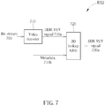
- FIG. 7 is a receiver RX 2 according to an example of the present invention.
- the receiver RX 2 may be used for realizing the receiver RX (the decoder 140 and/or the postprocessing module 160 ) in FIG. 1 , and includes modules performing different signal processing functions on a bit stream 700 .
- a video decoder 710 e.g., AVS decoder
- processes the bit stream 700 to generate a HDR YUV signal 710 a (e.g., format 4:2:0) and metadata 710 b .
- a 3D lookup table 720 is used for generating a SDR YUV signal 720 a (e.g., format 4:2:0) according to the HDR YUV signal 710 a and the metadata 710 b . Then, the receiver RX 2 may playback the SDR YUV signal 720 a.
- a SDR YUV signal 720 a e.g., format 4:2:0
- the third application includes transmitting a first format of a HDR video sequence as a base video sequence and a second format of the HDR video sequence. Contrast is one of important factors in how good a TV picture looks and it is a key part of a HDR TV.
- Peak brightness refers to how bright a TV can go, and is measured in a unit of “nit”.
- the peak brightness reached by HDR TVs may be different. For example, a TV may have a peak brightness of 400 nits while another TV may have a peak brightness of 1000 nits.
- one format of a HDR video sequence is transmitted as a base video sequence and a 3D lookup table maps the format of the HDR video sequence to another format of the HDR video sequence in metadata.
- the supported formats of the HDR video sequence can be any of the following combinations: two HDR video sequences of different nits, hybrid Log-Gamma HDR/Perceptual Quantizer HDR (HLG HDR/PQ HDR) and PQ HDR/HLG HDR.
- FIG. 8 is a transmitter TX 5 according to an example of the present invention.
- the transmitter TX 5 may be used for realizing the transmitter TX (the preprocessing module 110 and/or the encoder 130 ) in FIG. 1 , and includes modules performing different signal processing functions on raw data 800 .
- the raw data 800 may be generated by a video capturing device or an editing device.
- the transmitter TX 5 processes the raw data 800 , to generate a HDR YUV signal 810 (e.g., format HDR HLG) and a HDR YUV signal 820 (e.g., format HDR PQ). Formats (e.g., luminance, peak brightness, etc.) of the HDR YUV signals 810 and 820 are different.
- a 3D lookup table 830 is used for generating metadata 830 a according to the HDR YUV signals 810 and 820 .
- the metadata 830 a provides additional information by describing a relation between the HDR YUV signals 810 and 820 .
- the transmitter TX 5 may transmit the HDR YUV signal 820 and the metadata 830 a in a bit stream, e.g., to the receiver RX.
- FIG. 9 is a receiver RX 3 according to an example of the present invention.
- the receiver RX 3 may be used for realizing the receiver RX (the decoder 140 and/or the postprocessing module 160 ) in FIG. 1 , and includes modules performing different signal processing functions on a bit stream 900 .
- a video decoder 910 e.g., AVS decoder
- processes the bit stream 900 to generate a HDR YUV signal 910 a (e.g., format HDR PQ) and metadata 910 b .
- HDR YUV signal 910 a e.g., format HDR PQ
- a 3D lookup table 920 is used for generating a HDR YUV signal 920 a (e.g., format HDR HLG) according to the HDR YUV signal 910 a and the metadata 910 b . Then, the receiver RX 3 may playback the HDR YUV signal 920 a.
- a HDR YUV signal 920 a e.g., format HDR HLG
- HDR raw data are retrieved from a video capturing device directly, the HDR raw data may need to be transferred to a HDR YUV 4:2:0 format compatible with common encoders.
- a procedure in HDR 10 standard is adopted in the present invention.
- FIG. 10 is a HDR generator 1000 according to an example of the present invention.
- the HDR generator 1000 may be used for realizing any of the abovementioned HDR generators or for generating a HDR signal or a HDR video sequence, and is not limited herein.
- the HDR generator 1000 includes modules performing different signal processing functions on a HDR source 1002 .
- the HDR source 1002 is processed by using a curve transform 1004 , and a resulted signal 1004 a is generated and provided to a R′G′B′ to Y′CbCr conversion 1006 . Accordingly, a resulted signal 1006 a is generated and provided to a 10 bit quantization 1008 , and a quantized signal 1008 a is generated.
- the quantized signal 1008 a is processed by a 4:4:4 to 4:2:0 conversion 1010 (i.e., downsampling), and a HDR YUV signal 1012 is generated.
- the first SDR generation method includes generating a SDR signal according to a HDR signal generated by a video capturing device or an editing device.
- the second SDR generation method includes generating a SDR signal according to a HDR signal which is ready for encoding/transmitting.
- FIG. 11 is a SDR generator 1100 according to an example of the present invention.
- the SDR generator 1100 may be used for realizing any of the abovementioned SDR generators or for generating a SDR signal or a SDR video sequence, and is not limited herein.
- the SDR generator 1100 includes modules performing different signal processing functions on a linear RGB signal 1102 .
- the linear RGB signal 1102 is processed by using a Luma adjustment 1104 , to generate an adjusted signal 1104 a .
- the R, G, B component values are multiplied by the Luma adjustment value k
- the R, G, B component values are further shaped by a SDR generation curve 1106 , to generate a resulted signal 1106 a .
- the SDR generation curve 1106 may be selected according to a ITU 1886 standard, a ITU 709 standard or a HLG standard.
- a color space transform 1108 is performed on the resulted signal 1106 a , to generate a transformed signal 1108 a .
- the transformed signal 1108 a is processed by a 10 bit quantization 1110 , to generate a quantized signal 1110 a .
- a downsampling 1112 is performed on the quantized signal 1110 a , to generate a SDR YUV signal 1114 .
- FIG. 12 is a SDR generator 1200 according to an example of the present invention.
- the SDR generator 1200 may be used for realizing any of the abovementioned SDR generators or for generating a SDR signal or a SDR video sequence, and is not limited herein.
- the SDR generator 1200 includes modules performing different signal processing functions on a HDR signal 1202 .
- the HDR signal 1202 may be a HDR YUV signal with a transform curve, which is ready for encoding/transmitting.
- the HDR signal 1202 is processed by using an auto parameter calculation 1204 , to generate a mapping curve parameter f which is used for adjusting a quality of final SDR content.
- a luma component of the HDR signal 1202 (e.g., signal Y) is processed by a HDR to SDR function 1206 (i.e., luma mapping), to generate a SDR signal 1206 a .
- a chroma component of the HDR signal 1202 (e.g., signal CbCr) is processed by a downsampling function 1208 and is then processed with the luma component of the HDR signal 1202 by a HDR to SDR function 1210 (i.e., chroma mapping), to generate a SDR signal 1210 a .
- a SDR YUV signal 1212 (e.g., format 4:2:0) is obtained according to the SDR signal 1206 a and the SDR signal 1210 a . That is, the luma component and the chroma component of the HDR signal 1202 are mapped from HDR to SDR separately to the SDR YUV signal 1212 .
- the chroma transform is performed in 1 ⁇ 4 pixel resolution.
- One major advantage of the present example is low implementation complexity as no full resolution color space transform is needed.
- a luminance in SDR may be generated as follows. Given a YUV 4:2:0 signal with transform curve and Y 0 , a classic mapping function may be used for mapping each Luma sample to Y t which is quantized to Y s , where Y s is its SDR value ranged between 0 and (2 N ⁇ 1).
- the classic mapping function may be performed according to the following equations:
- Y t log ⁇ ( Y 0 f + 1 ) log ⁇ ( P f + 1 ) ( Eq . ⁇ 2 )
- Y s ( 2 N - 1 )
- Y t ( 2 N - 1 )
- P is the maximum luminance.
- f is a parameter for controlling a curvature of the classic mapping function and is based on an average luma value of input HDR L mean .
- the values of a, b and c may be derived based on experimental results. According to the above equations, the HDR to SDR process is essentially a non-linear normalization of Y 0 from [0, P] to [0, 1].
- a chromaticity in SDR may be generated as follows. Given a RGB signal in 1 ⁇ 4 resolution, its linear luminance Y 0 and chroma U 0 and V 0 can be calculated as follows:
- the luminance in the HDR to SDR process is the same as that in the previous step, except that the resolution of Y 0 and Y s is 1 ⁇ 4 of that in the previous step.
- the RGB signal in 1 ⁇ 4 resolution is rescaled to a RsGsBs signal according to the following equation, where the RsGsBs signal is the SDR signal in the RGB domain.
- a CbCr signal may be calculated according to the RsGsBs signal according to the following equation:
- a non-linear function is used to map a value from a linear HDR domain to the SDR range. It may not be necessary to converse RGB to a non-linear HDR domain first as the goal for the HDR to SDR conversion is not conserving perceptual details.
- a set of steps are proposed for preprocessing (e.g., the preprocessing module 110 ):
- Step 2 Divide the original color space into 4 ⁇ 2 ⁇ 2 cubes.
- Step 3 Collect pixel values in each cube and corresponding pixel positions.
- Step 4 Collect target color space pixel values according to the pixel positions obtained in Step 3.
- Step 5 Calculate Y, U, V color mapping coefficients in each cube based on a 3D lookup table.
- Step 6 Transmit the Y, U, V color mapping coefficients in a bit stream.
- Step 5 is realized as follows.
- the transmitter TX only transmits a base video sequence and metadata.
- a mapping method i.e., a 3D lookup table, between the additional format(s) of the base video sequence and the base video sequence is proposed.
- the main idea of the 3D lookup table is using a matrix to map or to predict the additional format(s) of the base video sequence based on the base video sequence.
- LMS least mean square
- a color space of the base video sequence is further divided into several small cubes as shown in FIG. 13 , which is a schematic diagram of division of a base video color space according to an example of the present invention. For each cube, corresponding groups of coefficients are calculated and transmitted as metadata individually.
- a set of steps are proposed for postprocessing (e.g., the postprocessing module 160 ):
- Step 7 Decode the Y, U, V color mapping coefficients.
- Step 9 Calculate the target color space pixel values based on the 3D lookup table.
- Examples of the hardware may include analog circuit(s), digital circuit (s) and/or mixed circuit (s).
- the hardware may include application-specific integrated circuit(s) (ASIC(s)), field programmable gate array(s) (FPGA(s)), programmable logic device(s), coupled hardware components or combination thereof.
- ASIC application-specific integrated circuit
- FPGA field programmable gate array
- programmable logic device(s) programmable logic device(s)
- coupled hardware components or combination thereof the hardware includes general-purpose processor(s), microprocessor(s), controller(s), digital signal processor(s) (DSP(s)) or combination thereof.
- DSP(s) digital signal processor
- Examples of the software may include set(s) of codes, set(s) of instructions and/or set(s) of functions retained (e.g., stored) in a storage unit, e.g., a computer-readable medium.
- the computer-readable medium may include Subscriber Identity Module (SIM), Read-Only Memory (ROM), flash memory, Random Access Memory (RAM), CD-ROM/DVD-ROM/BD-ROM, magnetic tape, hard disk, optical data storage device, non-volatile storage unit, or combination thereof.
- SIM Subscriber Identity Module
- ROM Read-Only Memory
- RAM Random Access Memory
- CD-ROM/DVD-ROM/BD-ROM Compact Disc-Read Only Memory
- magnetic tape e.g., hard disk
- optical data storage device e.g., optical data storage unit, or combination thereof.
- the computer-readable medium e.g., storage unit
- the at least one processor which may include one or more modules may (e.g., be configured to) execute the software in the computer-readable medium.
- the set(s) of codes, the set(s) of instructions and/or the set(s) of functions may cause the at least one processor, the module(s), the hardware and/or the electronic system to perform the related steps.
- the present invention provides a device and method for handling multiple formats of a video sequence.
- a transmission of redundant video information is avoided.
- consumption of a bandwidth and a power of a transmitter can be reduced.
Landscapes
- Engineering & Computer Science (AREA)
- Multimedia (AREA)
- Signal Processing (AREA)
- Physics & Mathematics (AREA)
- General Physics & Mathematics (AREA)
- Theoretical Computer Science (AREA)
- Two-Way Televisions, Distribution Of Moving Picture Or The Like (AREA)
Abstract
Description
k=Y (1-gamma)/gamma (Eq.1)
wherein gamma is a system input. After the R, G, B component values are multiplied by the Luma adjustment value k, the R, G, B component values are further shaped by a
where P is the maximum luminance. f is a parameter for controlling a curvature of the classic mapping function and is based on an average luma value of input HDR Lmean. f is calculated according to the following equation:
f=a*L mean *L mean +b*L mean +c (Eq.4)
where a=0.00001, b=0.0001, c=0.3. The values of a, b and c may be derived based on experimental results. According to the above equations, the HDR to SDR process is essentially a non-linear normalization of Y0 from [0, P] to [0, 1].
where k is max(YE_max/YB_max, 1), which is used to reduce the value range of a, b, c, d for a better transmission efficiency. Mapping coefficients can be obtained according to a least mean square (LMS) method as follows:
Claims (9)
Priority Applications (2)
| Application Number | Priority Date | Filing Date | Title |
|---|---|---|---|
| US16/172,900 US10972767B2 (en) | 2017-11-01 | 2018-10-29 | Device and method of handling multiple formats of a video sequence |
| CN201811296468.4A CN109756777B (en) | 2017-11-01 | 2018-11-01 | Transmitting end, receiving end and method for processing multiple formats of image sequence |
Applications Claiming Priority (2)
| Application Number | Priority Date | Filing Date | Title |
|---|---|---|---|
| US201762579902P | 2017-11-01 | 2017-11-01 | |
| US16/172,900 US10972767B2 (en) | 2017-11-01 | 2018-10-29 | Device and method of handling multiple formats of a video sequence |
Publications (2)
| Publication Number | Publication Date |
|---|---|
| US20190132617A1 US20190132617A1 (en) | 2019-05-02 |
| US10972767B2 true US10972767B2 (en) | 2021-04-06 |
Family
ID=66245758
Family Applications (1)
| Application Number | Title | Priority Date | Filing Date |
|---|---|---|---|
| US16/172,900 Active 2038-12-13 US10972767B2 (en) | 2017-11-01 | 2018-10-29 | Device and method of handling multiple formats of a video sequence |
Country Status (2)
| Country | Link |
|---|---|
| US (1) | US10972767B2 (en) |
| CN (1) | CN109756777B (en) |
Families Citing this family (4)
| Publication number | Priority date | Publication date | Assignee | Title |
|---|---|---|---|---|
| US11405582B2 (en) * | 2019-06-28 | 2022-08-02 | Meta Platforms, Inc. | Preprocessing of high-dynamic-range video using a hybrid lookup table scheme |
| CN112468793B (en) * | 2020-11-24 | 2022-06-10 | 深圳创维-Rgb电子有限公司 | Color adjusting method and device of OLED screen and computer readable storage medium |
| JP2024506524A (en) * | 2021-01-25 | 2024-02-14 | ボリュームズ テクノロジーズ リミテッド | Publication file system and method |
| US11606605B1 (en) * | 2021-09-30 | 2023-03-14 | Samsung Electronics Co., Ltd. | Standard dynamic range (SDR) / hybrid log-gamma (HLG) with high dynamic range (HDR) 10+ |
Citations (12)
| Publication number | Priority date | Publication date | Assignee | Title |
|---|---|---|---|---|
| US20100309987A1 (en) * | 2009-06-05 | 2010-12-09 | Apple Inc. | Image acquisition and encoding system |
| CN102959957A (en) | 2010-07-06 | 2013-03-06 | 皇家飞利浦电子股份有限公司 | Generation of high dynamic range images from low dynamic range images in multi-view video coding |
| US20150042890A1 (en) * | 2011-10-20 | 2015-02-12 | Dolby Laboratories Licensing Corporation | Method and system for video equalization |
| US20150245043A1 (en) * | 2014-02-25 | 2015-08-27 | Apple Inc. | Display-side adaptive video processing |
| CN104969259A (en) | 2012-11-16 | 2015-10-07 | 汤姆逊许可公司 | Processing high dynamic range images |
| US20160330513A1 (en) * | 2014-08-19 | 2016-11-10 | Panasonic Intellectual Property Management Co., Ltd. | Method for transmitting appropriate meta data to display device according to transmission protocol version |
| US20170105042A1 (en) * | 2014-06-26 | 2017-04-13 | Panasonic Intellectual Property Management Co., Ltd. | Method for generating control information based on characteristic data included in metadata |
| US20180020128A1 (en) * | 2015-03-05 | 2018-01-18 | Sony Corporation | Transmitting device, transmitting method, receiving device, and receiving method |
| US20180278967A1 (en) * | 2015-09-21 | 2018-09-27 | Vid Scale, Inc. | Inverse reshaping for high dynamic range video coding |
| US20190132600A1 (en) * | 2016-05-04 | 2019-05-02 | Thomson Licensing | Method and apparatus for encoding/decoding a scalar integer into a parameter representative of a pivot points of a piece-wise linear function |
| US20190259353A1 (en) * | 2016-11-14 | 2019-08-22 | SZ DJI Technology Co., Ltd. | Image processing method, apparatus, device, and video image transmission system |
| US20200193573A1 (en) * | 2017-04-27 | 2020-06-18 | Interdigital Vc Holdings, Inc. | Method and device for color gamut mapping |
Family Cites Families (10)
| Publication number | Priority date | Publication date | Assignee | Title |
|---|---|---|---|---|
| EP2684365A1 (en) * | 2011-03-10 | 2014-01-15 | Dolby Laboratories Licensing Corporation | Bitdepth and color scalable video coding |
| RU2670782C9 (en) * | 2013-07-18 | 2018-11-23 | Конинклейке Филипс Н.В. | Methods and devices for creating code mapping functions for hdr image coding and methods and devices for using such encoded images |
| EP3111416A1 (en) * | 2014-02-26 | 2017-01-04 | Thomson Licensing | Method and apparatus for encoding and decoding hdr images |
| JP6330507B2 (en) * | 2014-06-19 | 2018-05-30 | ソニー株式会社 | Image processing apparatus and image processing method |
| WO2015193113A1 (en) * | 2014-06-20 | 2015-12-23 | Thomson Licensing | Method and device for signaling in a bitstream a picture/video format of an ldr picture and a picture/video format of a decoded hdr picture obtained from said ldr picture and an illumination picture. |
| EP2958075A1 (en) * | 2014-06-20 | 2015-12-23 | Thomson Licensing | Method and apparatus for dynamic range expansion of LDR video sequence |
| EP3051821A1 (en) * | 2015-01-30 | 2016-08-03 | Thomson Licensing | Method and apparatus for encoding and decoding high dynamic range (HDR) videos |
| EP3099073A1 (en) * | 2015-05-27 | 2016-11-30 | Thomson Licensing | Method and device of encoding/decoding a hdr and a sdr picture in/from a scalable bitstream |
| KR102140083B1 (en) * | 2015-09-23 | 2020-07-31 | 애리스 엔터프라이지즈 엘엘씨 | System for reshaping and coding high dynamic range and wide color gamut sequences |
| CN106878694B (en) * | 2015-12-10 | 2018-12-18 | 瑞昱半导体股份有限公司 | high dynamic range signal processing system and method |
-
2018
- 2018-10-29 US US16/172,900 patent/US10972767B2/en active Active
- 2018-11-01 CN CN201811296468.4A patent/CN109756777B/en active Active
Patent Citations (12)
| Publication number | Priority date | Publication date | Assignee | Title |
|---|---|---|---|---|
| US20100309987A1 (en) * | 2009-06-05 | 2010-12-09 | Apple Inc. | Image acquisition and encoding system |
| CN102959957A (en) | 2010-07-06 | 2013-03-06 | 皇家飞利浦电子股份有限公司 | Generation of high dynamic range images from low dynamic range images in multi-view video coding |
| US20150042890A1 (en) * | 2011-10-20 | 2015-02-12 | Dolby Laboratories Licensing Corporation | Method and system for video equalization |
| CN104969259A (en) | 2012-11-16 | 2015-10-07 | 汤姆逊许可公司 | Processing high dynamic range images |
| US20150245043A1 (en) * | 2014-02-25 | 2015-08-27 | Apple Inc. | Display-side adaptive video processing |
| US20170105042A1 (en) * | 2014-06-26 | 2017-04-13 | Panasonic Intellectual Property Management Co., Ltd. | Method for generating control information based on characteristic data included in metadata |
| US20160330513A1 (en) * | 2014-08-19 | 2016-11-10 | Panasonic Intellectual Property Management Co., Ltd. | Method for transmitting appropriate meta data to display device according to transmission protocol version |
| US20180020128A1 (en) * | 2015-03-05 | 2018-01-18 | Sony Corporation | Transmitting device, transmitting method, receiving device, and receiving method |
| US20180278967A1 (en) * | 2015-09-21 | 2018-09-27 | Vid Scale, Inc. | Inverse reshaping for high dynamic range video coding |
| US20190132600A1 (en) * | 2016-05-04 | 2019-05-02 | Thomson Licensing | Method and apparatus for encoding/decoding a scalar integer into a parameter representative of a pivot points of a piece-wise linear function |
| US20190259353A1 (en) * | 2016-11-14 | 2019-08-22 | SZ DJI Technology Co., Ltd. | Image processing method, apparatus, device, and video image transmission system |
| US20200193573A1 (en) * | 2017-04-27 | 2020-06-18 | Interdigital Vc Holdings, Inc. | Method and device for color gamut mapping |
Also Published As
| Publication number | Publication date |
|---|---|
| US20190132617A1 (en) | 2019-05-02 |
| CN109756777A (en) | 2019-05-14 |
| CN109756777B (en) | 2021-10-12 |
Similar Documents
| Publication | Publication Date | Title |
|---|---|---|
| US20230171429A1 (en) | Color volume transforms in coding of high dynamic range and wide color gamut sequences | |
| US10116954B2 (en) | High dynamic range adaptation operations at a video decoder | |
| CN107203974B (en) | Method, apparatus and system for extended high dynamic range HDR to HDR tone mapping | |
| US9936199B2 (en) | Encoding and decoding perceptually-quantized video content | |
| CN110177230B (en) | Reproduction method and reproduction device | |
| US10356444B2 (en) | Method and apparatus for encoding and decoding high dynamic range (HDR) videos | |
| RU2737507C2 (en) | Method and device for encoding an image of a high dynamic range, a corresponding decoding method and a decoding device | |
| CN111316625B (en) | Method and apparatus for generating a second image from a first image | |
| US20180005357A1 (en) | Method and device for mapping a hdr picture to a sdr picture and corresponding sdr to hdr mapping method and device | |
| US10972767B2 (en) | Device and method of handling multiple formats of a video sequence | |
| US10600163B2 (en) | Method and device for reconstructing a display adapted HDR image | |
| EP3672219A1 (en) | Method and device for determining control parameters for mapping an input image with a high dynamic range to an output image with a lower dynamic range | |
| TW201638879A (en) | Method and apparatus for encoding and decoding high dynamic range (HDR) videos | |
| KR102885506B1 (en) | Image decoding | |
| EP3493542A1 (en) | Saturation control for high-dynamic range reconstruction | |
| US11785193B2 (en) | Processing an image | |
| WO2023144091A1 (en) | Method for limiting effects of quantization in a color gamut modification process applied to a video content | |
| CN112425168B (en) | Method and device for encoding images | |
| EP3099073A1 (en) | Method and device of encoding/decoding a hdr and a sdr picture in/from a scalable bitstream | |
| EP3528201A1 (en) | Method and device for controlling saturation in a hdr image |
Legal Events
| Date | Code | Title | Description |
|---|---|---|---|
| AS | Assignment |
Owner name: REALTEK SEMICONDUCTOR CORP., TAIWAN Free format text: ASSIGNMENT OF ASSIGNORS INTEREST;ASSIGNORS:LIU, LINGZHI;LIU, LI;WANG, JING;AND OTHERS;SIGNING DATES FROM 20180913 TO 20181002;REEL/FRAME:047334/0488 |
|
| FEPP | Fee payment procedure |
Free format text: ENTITY STATUS SET TO UNDISCOUNTED (ORIGINAL EVENT CODE: BIG.); ENTITY STATUS OF PATENT OWNER: LARGE ENTITY |
|
| STPP | Information on status: patent application and granting procedure in general |
Free format text: DOCKETED NEW CASE - READY FOR EXAMINATION |
|
| STPP | Information on status: patent application and granting procedure in general |
Free format text: NON FINAL ACTION MAILED |
|
| STPP | Information on status: patent application and granting procedure in general |
Free format text: RESPONSE TO NON-FINAL OFFICE ACTION ENTERED AND FORWARDED TO EXAMINER |
|
| STPP | Information on status: patent application and granting procedure in general |
Free format text: FINAL REJECTION MAILED |
|
| STPP | Information on status: patent application and granting procedure in general |
Free format text: DOCKETED NEW CASE - READY FOR EXAMINATION |
|
| STPP | Information on status: patent application and granting procedure in general |
Free format text: FINAL REJECTION MAILED |
|
| STPP | Information on status: patent application and granting procedure in general |
Free format text: PUBLICATIONS -- ISSUE FEE PAYMENT RECEIVED |
|
| STPP | Information on status: patent application and granting procedure in general |
Free format text: PUBLICATIONS -- ISSUE FEE PAYMENT VERIFIED |
|
| STCF | Information on status: patent grant |
Free format text: PATENTED CASE |
|
| MAFP | Maintenance fee payment |
Free format text: PAYMENT OF MAINTENANCE FEE, 4TH YEAR, LARGE ENTITY (ORIGINAL EVENT CODE: M1551); ENTITY STATUS OF PATENT OWNER: LARGE ENTITY Year of fee payment: 4 |