WO2014148070A1 - Image processing device and image processing method - Google Patents
Image processing device and image processing method Download PDFInfo
- Publication number
- WO2014148070A1 WO2014148070A1 PCT/JP2014/050483 JP2014050483W WO2014148070A1 WO 2014148070 A1 WO2014148070 A1 WO 2014148070A1 JP 2014050483 W JP2014050483 W JP 2014050483W WO 2014148070 A1 WO2014148070 A1 WO 2014148070A1
- Authority
- WO
- WIPO (PCT)
- Prior art keywords
- filter
- image
- unit
- layer
- upsampling
- Prior art date
Links
Images


Classifications
-
- G—PHYSICS
- G06—COMPUTING; CALCULATING OR COUNTING
- G06T—IMAGE DATA PROCESSING OR GENERATION, IN GENERAL
- G06T5/00—Image enhancement or restoration
- G06T5/10—Image enhancement or restoration by non-spatial domain filtering
-
- H—ELECTRICITY
- H04—ELECTRIC COMMUNICATION TECHNIQUE
- H04N—PICTORIAL COMMUNICATION, e.g. TELEVISION
- H04N19/00—Methods or arrangements for coding, decoding, compressing or decompressing digital video signals
- H04N19/10—Methods or arrangements for coding, decoding, compressing or decompressing digital video signals using adaptive coding
- H04N19/102—Methods or arrangements for coding, decoding, compressing or decompressing digital video signals using adaptive coding characterised by the element, parameter or selection affected or controlled by the adaptive coding
- H04N19/132—Sampling, masking or truncation of coding units, e.g. adaptive resampling, frame skipping, frame interpolation or high-frequency transform coefficient masking
-
- H—ELECTRICITY
- H04—ELECTRIC COMMUNICATION TECHNIQUE
- H04N—PICTORIAL COMMUNICATION, e.g. TELEVISION
- H04N19/00—Methods or arrangements for coding, decoding, compressing or decompressing digital video signals
- H04N19/10—Methods or arrangements for coding, decoding, compressing or decompressing digital video signals using adaptive coding
- H04N19/169—Methods or arrangements for coding, decoding, compressing or decompressing digital video signals using adaptive coding characterised by the coding unit, i.e. the structural portion or semantic portion of the video signal being the object or the subject of the adaptive coding
- H04N19/187—Methods or arrangements for coding, decoding, compressing or decompressing digital video signals using adaptive coding characterised by the coding unit, i.e. the structural portion or semantic portion of the video signal being the object or the subject of the adaptive coding the unit being a scalable video layer
-
- G—PHYSICS
- G06—COMPUTING; CALCULATING OR COUNTING
- G06T—IMAGE DATA PROCESSING OR GENERATION, IN GENERAL
- G06T2207/00—Indexing scheme for image analysis or image enhancement
- G06T2207/10—Image acquisition modality
- G06T2207/10024—Color image
Landscapes
- Engineering & Computer Science (AREA)
- Multimedia (AREA)
- Signal Processing (AREA)
- Physics & Mathematics (AREA)
- General Physics & Mathematics (AREA)
- Theoretical Computer Science (AREA)
- Compression Or Coding Systems Of Tv Signals (AREA)
Abstract
[Problem] To adaptively control the configuration of an upsampling filter while avoiding degradation in image quality. [Solution] Provided is an image processing device comprising: an upsampling filter that upsamples an image in a first layer which is referenced at the time of decoding an image in a second layer having a higher spatial resolution than the first layer; and a control unit that changes the filter configuration of the upsampling filter for every block in said image.
Description
本開示は、画像処理装置及び画像処理方法に関する。
The present disclosure relates to an image processing apparatus and an image processing method.
現在、H.264/AVCよりも符号化効率をさらに向上することを目的として、ITU-TとISO/IECとの共同の標準化団体であるJCTVC(Joint Collaboration Team-Video Coding)により、HEVC(High Efficiency Video Coding)と呼ばれる画像符号化方式の標準化が進められている(例えば、非特許文献1参照)。
Currently H. For the purpose of further improving the encoding efficiency over H.264 / AVC, JVCVC (Joint Collaboration Team-Video Coding), a joint standardization organization of ITU-T and ISO / IEC, has made HEVC (High Efficiency Video Coding) The standardization of an image encoding method called “N” is underway (see, for example, Non-Patent Document 1).
HEVCは、MPEG2及びAVC(Advanced Video Coding)などの既存の画像符号化方式と同様、シングルレイヤの符号化のみならず、スケーラブル符号化をも提供する。HEVCのスケーラブル符号化技術を、SHVC(Scalable HEVC)ともいう(例えば、非特許文献2参照)。
HEVC provides not only single-layer coding but also scalable coding as well as existing image coding schemes such as MPEG2 and AVC (Advanced Video Coding). HEVC scalable coding technology is also referred to as SHVC (Scalable HEVC) (see, for example, Non-Patent Document 2).
スケーラブル符号化とは、一般には、粗い画像信号を伝送するレイヤと精細な画像信号を伝送するレイヤとを階層的に符号化する技術をいう。スケーラブル符号化において階層化される典型的な属性は、主に次の3種類である。
-空間スケーラビリティ:空間解像度あるいは画像サイズが階層化される。
-時間スケーラビリティ:フレームレートが階層化される。
-SNR(Signal to Noise Ratio)スケーラビリティ:SN比が階層化される。
さらに、標準規格で未だ採用されていないものの、ビット深度スケーラビリティ及びクロマフォーマットスケーラビリティもまた議論されている。 Scalable encoding generally refers to a technique for hierarchically encoding a layer that transmits a coarse image signal and a layer that transmits a fine image signal. Typical attributes hierarchized in scalable coding are mainly the following three types.
Spatial scalability: Spatial resolution or image size is layered.
-Time scalability: Frame rate is layered.
-SNR (Signal to Noise Ratio) scalability: SN ratio is hierarchized.
In addition, bit depth scalability and chroma format scalability are also discussed, although not yet adopted by the standard.
空間スケーラビリティを実現するスケーラブル符号化では、下位レイヤの画像は、アップサンプリングされた後、上位レイヤの画像を符号化し又は復号するために用いられる。非特許文献2によれば、SHVCにおいて利用されるアップサンプリングフィルタは、動き補償のための補間(interpolation)フィルタと同様に設計される。非特許文献1において定義されている動き補償のための補間フィルタは、輝度成分について7タップ又は8タップ、色差成分について4タップのタップ数を有する。
In scalable coding that realizes spatial scalability, the lower layer image is up-sampled and then used to encode or decode the upper layer image. According to Non-Patent Document 2, an upsampling filter used in SHVC is designed in the same manner as an interpolation filter for motion compensation. The interpolation filter for motion compensation defined in Non-Patent Document 1 has a tap number of 7 taps or 8 taps for luminance components and 4 taps for color difference components.
非特許文献3では、インターレイヤ予測(inter-layer prediction)のためのいくつかの手法が提案されている。それら手法のうち、イントラBL予測(intra-BL prediction)では、ベースレイヤの復号画像がアップサンプリングされた後にエンハンスメントレイヤにおいて参照される。イントラ残差予測(intra residual prediction)及びインター残差予測(inter residual prediction)では、ベースレイヤの予測誤差(残差)画像がアップサンプリングされた後にエンハンスメントレイヤにおいて参照される。
Non-Patent Document 3 proposes several methods for inter-layer prediction. Among these methods, in intra-BL prediction (intra-BL prediction), the decoded image of the base layer is up-sampled and then referred to in the enhancement layer. In intra residual prediction (inter residual prediction) and inter residual prediction (inter residual prediction), a base layer prediction error (residual) image is up-sampled and then referred to in the enhancement layer.
一般的に、アップサンプリングの計算コストは、アップサンプリングフィルタの構成と空間解像度とに依存する。計算コストを抑制するためには例えばフィルタタップ数を削減することが望ましいが、フィルタタップ数の一律的な削減は画質の劣化を招来する。
Generally, the upsampling calculation cost depends on the configuration of the upsampling filter and the spatial resolution. In order to reduce the calculation cost, for example, it is desirable to reduce the number of filter taps. However, uniform reduction of the number of filter taps causes deterioration of image quality.
従って、画質の劣化を回避しつつアップサンプリングフィルタの構成を適応的に制御することのできる仕組みが提供されることが望ましい。
Therefore, it is desirable to provide a mechanism that can adaptively control the configuration of the upsampling filter while avoiding image quality degradation.
本開示によれば、第1レイヤよりも空間解像度の高い第2レイヤの画像を復号する際に参照される前記第1レイヤの画像をアップサンプリングするアップサンプリングフィルタと、画像のブロックごとに、前記アップサンプリングフィルタのフィルタ構成を切り替える制御部と、を備える画像処理装置が提供される。
According to the present disclosure, an upsampling filter that upsamples an image of the first layer referred to when decoding an image of the second layer having a higher spatial resolution than the first layer, and for each block of the image, There is provided an image processing apparatus including a control unit that switches a filter configuration of an upsampling filter.
上記画像処理装置は、画像を復号する画像復号装置として実現されてもよい。また、上記画像処理装置は、ローカルデコーダを含む画像符号化装置として実現されてもよい。
The image processing apparatus may be realized as an image decoding apparatus that decodes an image. The image processing apparatus may be realized as an image encoding apparatus including a local decoder.
また、本開示によれば、第1レイヤよりも空間解像度の高い第2レイヤの画像を復号する際に参照される前記第1レイヤの画像をアップサンプリングフィルタを用いてアップサンプリングすることと、画像のブロックごとに、前記アップサンプリングフィルタのフィルタ構成を切り替えることと、を含む画像処理方法が提供される。
According to the present disclosure, the first layer image referred to when decoding the second layer image having a higher spatial resolution than the first layer is upsampled using an upsampling filter; Switching the filter configuration of the upsampling filter for each block.
本開示に係る技術によれば、画質の劣化を回避しつつアップサンプリングフィルタの構成を適応的に制御することが可能となる。
According to the technique according to the present disclosure, it is possible to adaptively control the configuration of the upsampling filter while avoiding deterioration of image quality.
以下に添付図面を参照しながら、本開示の好適な実施の形態について詳細に説明する。なお、本明細書及び図面において、実質的に同一の機能構成を有する構成要素については、同一の符号を付することにより重複説明を省略する。
Hereinafter, preferred embodiments of the present disclosure will be described in detail with reference to the accompanying drawings. In addition, in this specification and drawing, about the component which has the substantially same function structure, duplication description is abbreviate | omitted by attaching | subjecting the same code | symbol.
また、以下の順序で説明を行う。
1.概要
1-1.スケーラブル符号化
1-2.ベースレイヤの画像のアップサンプリング
1-3.エンコーダの基本的な構成例
1-4.デコーダの基本的な構成例
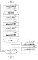
2.EL符号化部の構成例(第1の実施形態)
2-1.全体的な構成
2-2.アップサンプリング部(第1の実施例)
2-3.アップサンプリング部(第2の実施例)
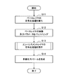
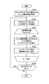
3.符号化時の処理の流れ(第1の実施形態)
3-1.概略的な流れ
3-2.アップサンプリング処理
3-3.変形例
4.EL復号部の構成例(第1の実施形態)
4-1.全体的な構成
4-2.アップサンプリング部(第1の実施例)
4-3.アップサンプリング部(第2の実施例)
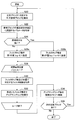
5.復号時の処理の流れ(第1の実施形態)
5-1.概略的な流れ
5-2.アップサンプリング処理
5-3.変形例
5-4.逆量子化処理
6.第2の実施形態
6-1.EL符号化部の構成例
6-2.EL復号部の構成例
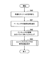
6-3.符号化時のアップサンプリング処理の流れ
6-4.復号時のアップサンプリング処理の流れ
7.応用例
7-1.様々な製品への応用
7-2.スケーラブル符号化の様々な用途
7-3.その他
8.まとめ The description will be given in the following order.
1. Outline 1-1. Scalable coding 1-2. Upsampling of base layer image 1-3. Basic configuration example of encoder 1-4. 1. Basic configuration example of decoder Configuration example of EL encoding unit (first embodiment)
2-1. Overall configuration 2-2. Upsampling unit (first embodiment)
2-3. Upsampling unit (second embodiment)
3. Process flow during encoding (first embodiment)
3-1. Schematic flow 3-2. Upsampling processing 3-3. Modified example 4. Configuration example of EL decoding unit (first embodiment)
4-1. Overall configuration 4-2. Upsampling unit (first embodiment)
4-3. Upsampling unit (second embodiment)
5. Flow of processing at the time of decoding (first embodiment)
5-1. Schematic flow 5-2. Upsampling processing 5-3. Modification 5-4. Inverse quantization processing 6. Second embodiment 6-1. Configuration example of EL encoding unit 6-2. Configuration example of EL decoding unit 6-3. Flow of upsampling process during encoding 6-4. 6. Flow of upsampling process during decoding Application example 7-1. Application to various products 7-2. Various uses of scalable coding 7-3.Others 8. Summary
1.概要
1-1.スケーラブル符号化
1-2.ベースレイヤの画像のアップサンプリング
1-3.エンコーダの基本的な構成例
1-4.デコーダの基本的な構成例
2.EL符号化部の構成例(第1の実施形態)
2-1.全体的な構成
2-2.アップサンプリング部(第1の実施例)
2-3.アップサンプリング部(第2の実施例)
3.符号化時の処理の流れ(第1の実施形態)
3-1.概略的な流れ
3-2.アップサンプリング処理
3-3.変形例
4.EL復号部の構成例(第1の実施形態)
4-1.全体的な構成
4-2.アップサンプリング部(第1の実施例)
4-3.アップサンプリング部(第2の実施例)
5.復号時の処理の流れ(第1の実施形態)
5-1.概略的な流れ
5-2.アップサンプリング処理
5-3.変形例
5-4.逆量子化処理
6.第2の実施形態
6-1.EL符号化部の構成例
6-2.EL復号部の構成例
6-3.符号化時のアップサンプリング処理の流れ
6-4.復号時のアップサンプリング処理の流れ
7.応用例
7-1.様々な製品への応用
7-2.スケーラブル符号化の様々な用途
7-3.その他
8.まとめ The description will be given in the following order.
1. Outline 1-1. Scalable coding 1-2. Upsampling of base layer image 1-3. Basic configuration example of encoder 1-4. 1. Basic configuration example of decoder Configuration example of EL encoding unit (first embodiment)
2-1. Overall configuration 2-2. Upsampling unit (first embodiment)
2-3. Upsampling unit (second embodiment)
3. Process flow during encoding (first embodiment)
3-1. Schematic flow 3-2. Upsampling processing 3-3. Modified example 4. Configuration example of EL decoding unit (first embodiment)
4-1. Overall configuration 4-2. Upsampling unit (first embodiment)
4-3. Upsampling unit (second embodiment)
5. Flow of processing at the time of decoding (first embodiment)
5-1. Schematic flow 5-2. Upsampling processing 5-3. Modification 5-4. Inverse quantization processing 6. Second embodiment 6-1. Configuration example of EL encoding unit 6-2. Configuration example of EL decoding unit 6-3. Flow of upsampling process during encoding 6-4. 6. Flow of upsampling process during decoding Application example 7-1. Application to various products 7-2. Various uses of scalable coding 7-3.
<1.概要>
[1-1.スケーラブル符号化]
スケーラブル符号化においては、一連の画像をそれぞれ含む複数のレイヤが符号化される。ベースレイヤ(base layer)は、最初に符号化される、最も粗い画像を表現するレイヤである。ベースレイヤの符号化ストリームは、他のレイヤの符号化ストリームを復号することなく、独立して復号され得る。ベースレイヤ以外のレイヤは、エンハンスメントレイヤ(enhancement layer)と呼ばれる、より精細な画像を表現するレイヤである。エンハンスメントレイヤの符号化ストリームは、ベースレイヤの符号化ストリームに含まれる情報を用いて符号化される。従って、エンハンスメントレイヤの画像を再現するためには、ベースレイヤ及びエンハンスメントレイヤの双方の符号化ストリームが復号されることになる。スケーラブル符号化において扱われるレイヤの数は、2つ以上のいかなる数であってもよい。3つ以上のレイヤが符号化される場合には、最下位のレイヤがベースレイヤ、残りの複数のレイヤがエンハンスメントレイヤである。より上位のエンハンスメントレイヤの符号化ストリームは、より下位のエンハンスメントレイヤ又はベースレイヤの符号化ストリームに含まれる情報を用いて符号化され及び復号され得る。 <1. Overview>
[1-1. Scalable coding]
In scalable encoding, a plurality of layers each including a series of images are encoded. The base layer is a layer that expresses the coarsest image that is encoded first. The base layer coded stream may be decoded independently without decoding the other layer coded streams. A layer other than the base layer is a layer called an enhancement layer (enhancement layer) that represents a finer image. The enhancement layer encoded stream is encoded using information included in the base layer encoded stream. Accordingly, in order to reproduce the enhancement layer image, both the base layer and enhancement layer encoded streams are decoded. The number of layers handled in scalable coding may be any number of two or more. When three or more layers are encoded, the lowest layer is the base layer, and the remaining layers are enhancement layers. The higher enhancement layer encoded stream may be encoded and decoded using information contained in the lower enhancement layer or base layer encoded stream.
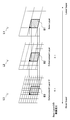
図1は、スケーラブル符号化される3つのレイヤL1、L2及びL3を示している。レイヤL1はベースレイヤであり、レイヤL2及びL3はエンハンスメントレイヤである。なお、ここでは、様々な種類のスケーラビリティのうち、空間スケーラビリティを例にとっている。レイヤL2のレイヤL1に対する空間解像度の比は、2:1である。レイヤL3のレイヤL1に対する空間解像度の比は、4:1である。なお、ここでの解像度比は一例に過ぎず、例えば1.5:1などの非整数の解像度比が使用されてもよい。レイヤL1のブロックB1は、ベースレイヤのピクチャ内の符号化処理の処理単位である。レイヤL2のブロックB2は、ブロックB1と共通するシーンを映したエンハンスメントレイヤのピクチャ内の符号化処理の処理単位である。ブロックB2は、レイヤL1のブロックB1に対応する。レイヤL3のブロックB3は、ブロックB1及びB2と共通するシーンを映したより上位のエンハンスメントレイヤのピクチャ内の符号化処理の処理単位である。ブロックB3は、レイヤL1のブロックB1及びレイヤL2のブロックB2に対応する。
FIG. 1 shows three layers L1, L2 and L3 to be scalable encoded. Layer L1 is a base layer, and layers L2 and L3 are enhancement layers. Here, spatial scalability is taken as an example among various types of scalability. The ratio of the spatial resolution of the layer L2 to the layer L1 is 2: 1. The ratio of the spatial resolution of layer L3 to layer L1 is 4: 1. The resolution ratio here is only an example, and a non-integer resolution ratio such as 1.5: 1 may be used. The block B1 of the layer L1 is a processing unit of the encoding process in the base layer picture. The block B2 of the layer L2 is a processing unit of the encoding process in the enhancement layer picture that shows a scene common to the block B1. Block B2 corresponds to block B1 of layer L1. The block B3 of the layer L3 is a processing unit for encoding processing in a picture of a higher enhancement layer that shows a scene common to the blocks B1 and B2. The block B3 corresponds to the block B1 of the layer L1 and the block B2 of the layer L2.
[1-2.ベースレイヤの画像のアップサンプリング]
図1に例示したレイヤ構造において、画像のテクスチャは、共通するシーンを映したレイヤ間で類似する。即ち、レイヤL1内のブロックB1、レイヤL2内のブロックB2、及びレイヤL3内のブロックB3のテクスチャは類似する。従って、例えばブロックB1を参照ブロックとして用いてブロックB2又はブロックB3の画素を予測し、又はブロックB2を参照ブロックとして用いてブロックB3の画素を予測すれば、高い予測精度が得られる可能性がある。このようなレイヤ間の予測を、インターレイヤ予測という。非特許文献3では、インターレイヤ予測のためのいくつかの手法が提案されている。それら手法のうち、イントラBL予測では、ベースレイヤの復号画像(リコンストラクト画像)が、エンハンスメントレイヤの復号画像を予測するための参照画像として使用される。イントラ残差予測及びインター残差予測では、ベースレイヤの予測誤差(残差)画像が、エンハンスメントレイヤの予測誤差画像を予測するための参照画像として使用される。空間スケーラビリティが実現される場合、エンハンスメントレイヤの空間解像度は、ベースレイヤの空間解像度よりも高い。従って、ベースレイヤの画像を参照画像として使用するためには、当該画像を解像度比に従ってアップサンプリングすることが求められる。 [1-2. Upsampling of base layer image]
In the layer structure illustrated in FIG. 1, the texture of an image is similar between layers that show a common scene. That is, the textures of the block B1 in the layer L1, the block B2 in the layer L2, and the block B3 in the layer L3 are similar. Therefore, for example, if the pixel of the block B2 or the block B3 is predicted using the block B1 as the reference block, or the pixel of the block B3 is predicted using the block B2 as the reference block, high prediction accuracy may be obtained. . Such prediction between layers is called inter-layer prediction.Non-Patent Document 3 proposes several methods for inter-layer prediction. Among these methods, in intra BL prediction, a decoded image (reconstructed image) of a base layer is used as a reference image for predicting a decoded image of an enhancement layer. In intra residual prediction and inter residual prediction, a base layer prediction error (residual) image is used as a reference image for predicting an enhancement layer prediction error image. When spatial scalability is realized, the spatial resolution of the enhancement layer is higher than the spatial resolution of the base layer. Therefore, in order to use a base layer image as a reference image, it is required to upsample the image according to a resolution ratio.
図1に例示したレイヤ構造において、画像のテクスチャは、共通するシーンを映したレイヤ間で類似する。即ち、レイヤL1内のブロックB1、レイヤL2内のブロックB2、及びレイヤL3内のブロックB3のテクスチャは類似する。従って、例えばブロックB1を参照ブロックとして用いてブロックB2又はブロックB3の画素を予測し、又はブロックB2を参照ブロックとして用いてブロックB3の画素を予測すれば、高い予測精度が得られる可能性がある。このようなレイヤ間の予測を、インターレイヤ予測という。非特許文献3では、インターレイヤ予測のためのいくつかの手法が提案されている。それら手法のうち、イントラBL予測では、ベースレイヤの復号画像(リコンストラクト画像)が、エンハンスメントレイヤの復号画像を予測するための参照画像として使用される。イントラ残差予測及びインター残差予測では、ベースレイヤの予測誤差(残差)画像が、エンハンスメントレイヤの予測誤差画像を予測するための参照画像として使用される。空間スケーラビリティが実現される場合、エンハンスメントレイヤの空間解像度は、ベースレイヤの空間解像度よりも高い。従って、ベースレイヤの画像を参照画像として使用するためには、当該画像を解像度比に従ってアップサンプリングすることが求められる。 [1-2. Upsampling of base layer image]
In the layer structure illustrated in FIG. 1, the texture of an image is similar between layers that show a common scene. That is, the textures of the block B1 in the layer L1, the block B2 in the layer L2, and the block B3 in the layer L3 are similar. Therefore, for example, if the pixel of the block B2 or the block B3 is predicted using the block B1 as the reference block, or the pixel of the block B3 is predicted using the block B2 as the reference block, high prediction accuracy may be obtained. . Such prediction between layers is called inter-layer prediction.
図2Aは、復号画像のアップサンプリングについて説明するための説明図である。図2Aの下段には、ベースレイヤ画像IMB1~IMB4が示されている。ベースレイヤ画像IMB1~IMB4は、ベースレイヤの符号化処理又は復号処理(エンコーダ内のローカルデコードを含む)において生成されるリコンストラクト画像である。ベースレイヤ画像は、レイヤ間の解像度比に応じて、アップサンプリングされる。図2Aの中段には、アップサンプリングされたベースレイヤ画像IMU1~IMU4が示されている。図2Aの上段には、エンハンスメントレイヤ画像IME1~IME4が示されている。一例として、エンハンスメントレイヤ画像IME1のブロックBE1が予測対象ブロックであるものとする。イントラBL予測が行われる場合、アップサンプリングされたベースレイヤ画像IMU1のブロックBU1を参照ブロックとして使用することにより、予測対象ブロックと参照ブロックとの間の解像度の差が解消される。そして、レイヤ間の画像の相関に基づいて高い予測精度を達成することができる。
FIG. 2A is an explanatory diagram for describing upsampling of a decoded image. In the lower part of FIG. 2A, base layer images IM B1 to IM B4 are shown. The base layer images IM B1 to IM B4 are reconstructed images generated in the base layer encoding process or decoding process (including local decoding in the encoder). The base layer image is upsampled according to the resolution ratio between layers. 2A shows up-sampled base layer images IM U1 to IM U4 . In the upper part of FIG. 2A, enhancement layer images IM E1 to IM E4 are shown. As an example, it is assumed block B E1 enhancement layer image IM E1 is the prediction target block. If the intra BL prediction is performed by using the block B U1 of upsampled base layer image IM U1 as a reference block, the difference resolution between the reference block and the prediction target block is eliminated. And high prediction precision can be achieved based on the correlation of the image between layers.
図2Bは、予測誤差画像のアップサンプリングについて説明するための説明図である。図2Bの下段にはベースレイヤ画像IMB1~IMB4が、上段にはエンハンスメントレイヤ画像IME1~IME4が再び示されている。一例として、エンハンスメントレイヤ画像IME3のブロックBE3がインター予測の予測対象ブロックであり、エンハンスメントレイヤ画像IMB2がインター予測の参照ピクチャであるものとする。さらにインター残差予測が行われる場合、ベースレイヤ画像IMB3のブロックBB3が、予測対象ブロックBE3のコロケーテッド(co-located)ブロックであり、インター残差予測の参照ブロックである。ブロックBB3の復号画像CurB、ベースレイヤにおけるインター予測の予測画像PredB及び予測誤差画像ErrBの間の関係は、次式のように表される。
FIG. 2B is an explanatory diagram for describing upsampling of a prediction error image. In the lower part of FIG. 2B, base layer images IM B1 to IM B4 are shown again, and in the upper part, enhancement layer images IM E1 to IM E4 are shown again. As an example, it is assumed that the block B E3 of the enhancement layer image IM E3 is a prediction target block for inter prediction, and the enhancement layer image IM B2 is a reference picture for inter prediction. Furthermore, when inter-residual prediction is performed, the block B B3 of the base layer image IM B3 is a collocated (co-located) blocks of the prediction target block B E3, a reference block of the inter residual prediction. The relationship among the decoded image Cur B of the block B B3 , the prediction image Pred B of inter prediction in the base layer, and the prediction error image Err B is expressed by the following equation.

そして、予測対象ブロックBE3の復号画像CurE、エンハンスメントレイヤにおけるインター予測の予測画像PredE及び予測誤差画像ErrEの間の関係は、アップサンプリングされたベースレイヤの予測誤差画像Up[ErrB]を用いて、次式のように表される。
The relationship between the decoded image Cur E of the prediction target block B E3 , the prediction image Pred E of the inter prediction in the enhancement layer, and the prediction error image Err E is the base layer prediction error image Up [Err B ]. Is expressed as follows.
このように、残差予測では、ベースレイヤの予測誤差画像をアップサンプリングすることにより、予測対象ブロックと参照ブロックとの間の解像度の差が解消される。そして、レイヤ間の予測誤差の相関に基づいて、符号化すべき予測誤差データ(ErrE)を削減することができる。
As described above, in the residual prediction, the difference in resolution between the prediction target block and the reference block is eliminated by upsampling the prediction error image of the base layer. Based on the correlation of prediction errors between layers, prediction error data (Err E ) to be encoded can be reduced.
なお、ここで説明したインターレイヤ予測は一例に過ぎない。即ち、上述したイントラBL予測及び残差予測とは異なる種類のインターレイヤ予測にも、本開示に係る技術は適用可能である。
Note that the inter-layer prediction described here is only an example. That is, the technology according to the present disclosure can be applied to a different type of inter-layer prediction from the above-described intra-BL prediction and residual prediction.
インターレイヤ予測のためのアップサンプリングフィルタは、通常、動き補償のための補間フィルタと同様に設計される。非特許文献1の8.5.3.2.2節“Fractional sample interpolation process”を参照すれば、動き補償のための補間フィルタは、輝度成分について7タップ又は8タップ、色差成分について4タップのタップ数を有する。タップ数がより多ければ画像の高域成分がより良好に再現されるため、アップサンプリングフィルタを十分なタップ数で構成することは、画質の維持又は向上の観点で重要である。しかし、アップサンプリングの計算コストは、アップサンプリングフィルタの構成と空間解像度とに依存する。アップサンプリングフィルタのタップ数が多ければ、アップサンプリングの計算コストもまた多大となる。そこで、以下に説明する第1の実施形態では、画像のブロックごとに、アップサンプリングフィルタのフィルタ構成が適応的に切り替えられる。第1の実施形態は、主に2つの実施例を含む。第1の実施例では、符号化側及び復号側の双方でブロックごとに画像の高域成分の強さが判定され、判定された高域成分の強さに応じてアップサンプリングフィルタのフィルタ構成が切り替えられる。特に、画像の高域成分が無く又は弱いブロックについては、タップ数が削減される結果として高域成分が再現されなくても顕著な画質の劣化は生じない。従って、アップサンプリングフィルタのフィルタ構成を適応的に切り替えることにより、画質の劣化を回避しつつアップサンプリングの計算コストを抑制することができる。第2の実施例では、符号化側でブロックごとに最適なフィルタ構成が判定され、判定されたフィルタ構成を示すフィルタ構成情報が符号化される。復号側では、復号されるフィルタ構成情報に従って、アップサンプリングフィルタのフィルタ構成が切り替えられる。第2の実施形態では、ピクチャ又はシーケンスなどのより粗い単位で、アップサンプリングフィルタのフィルタ構成が適応的に切り替えられる。
The upsampling filter for inter-layer prediction is usually designed in the same manner as the interpolation filter for motion compensation. If you refer to Section 8.5.5.3 “Fractional sample interpolation process” in Non-Patent Document 1, the interpolation filter for motion compensation is 7 taps or 8 taps for the luminance component and 4 taps for the color difference component. Has the number of taps. If the number of taps is larger, the high frequency component of the image is reproduced better. Therefore, it is important to configure the upsampling filter with a sufficient number of taps from the viewpoint of maintaining or improving the image quality. However, the computational cost of upsampling depends on the configuration of the upsampling filter and the spatial resolution. If the number of taps of the upsampling filter is large, the calculation cost of upsampling also increases. Therefore, in the first embodiment described below, the filter configuration of the upsampling filter is adaptively switched for each block of the image. The first embodiment mainly includes two examples. In the first embodiment, the strength of the high frequency component of the image is determined for each block on both the encoding side and the decoding side, and the upsampling filter has a filter configuration according to the determined strength of the high frequency component. Can be switched. In particular, for a block having no or weak high-frequency component of the image, no significant image quality degradation occurs even if the high-frequency component is not reproduced as a result of the reduction in the number of taps. Therefore, by adaptively switching the filter configuration of the upsampling filter, it is possible to suppress the upsampling calculation cost while avoiding the deterioration of the image quality. In the second embodiment, the optimum filter configuration is determined for each block on the encoding side, and filter configuration information indicating the determined filter configuration is encoded. On the decoding side, the filter configuration of the upsampling filter is switched according to the filter configuration information to be decoded. In the second embodiment, the filter configuration of the upsampling filter is adaptively switched in a coarser unit such as a picture or a sequence.
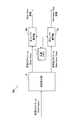
[1-3.エンコーダの基本的な構成例]
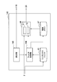
図3は、スケーラブル符号化をサポートする画像符号化装置10の概略的な構成を示すブロック図である。図3を参照すると、画像符号化装置10は、ベースレイヤ(BL)符号化部1a、エンハンスメントレイヤ(EL)符号化部1b、共通メモリ2及び多重化部3を備える。 [1-3. Basic encoder configuration example]
FIG. 3 is a block diagram illustrating a schematic configuration of theimage encoding device 10 that supports scalable encoding. Referring to FIG. 3, the image encoding device 10 includes a base layer (BL) encoding unit 1 a, an enhancement layer (EL) encoding unit 1 b, a common memory 2, and a multiplexing unit 3.
図3は、スケーラブル符号化をサポートする画像符号化装置10の概略的な構成を示すブロック図である。図3を参照すると、画像符号化装置10は、ベースレイヤ(BL)符号化部1a、エンハンスメントレイヤ(EL)符号化部1b、共通メモリ2及び多重化部3を備える。 [1-3. Basic encoder configuration example]
FIG. 3 is a block diagram illustrating a schematic configuration of the
BL符号化部1aは、ベースレイヤ画像を符号化し、ベースレイヤの符号化ストリームを生成する。EL符号化部1bは、エンハンスメントレイヤ画像を符号化し、エンハンスメントレイヤの符号化ストリームを生成する。共通メモリ2は、レイヤ間で共通的に利用される情報を記憶する。多重化部3は、BL符号化部1aにより生成されるベースレイヤの符号化ストリームと、EL符号化部1bにより生成される1つ以上のエンハンスメントレイヤの符号化ストリームとを多重化し、マルチレイヤの多重化ストリームを生成する。
The BL encoding unit 1a encodes a base layer image and generates a base layer encoded stream. The EL encoding unit 1b encodes the enhancement layer image, and generates an enhancement layer encoded stream. The common memory 2 stores information commonly used between layers. The multiplexing unit 3 multiplexes the encoded stream of the base layer generated by the BL encoding unit 1a and the encoded stream of one or more enhancement layers generated by the EL encoding unit 1b. Generate a multiplexed stream.
[1-4.デコーダの基本的な構成例]
図4は、スケーラブル符号化をサポートする画像復号装置60の概略的な構成を示すブロック図である。図4を参照すると、画像復号装置60は、逆多重化部5、ベースレイヤ(BL)復号部6a、エンハンスメントレイヤ(EL)復号部6b及び共通メモリ7を備える。 [1-4. Basic configuration example of decoder]
FIG. 4 is a block diagram showing a schematic configuration of animage decoding device 60 that supports scalable coding. Referring to FIG. 4, the image decoding device 60 includes a demultiplexing unit 5, a base layer (BL) decoding unit 6 a, an enhancement layer (EL) decoding unit 6 b, and a common memory 7.
図4は、スケーラブル符号化をサポートする画像復号装置60の概略的な構成を示すブロック図である。図4を参照すると、画像復号装置60は、逆多重化部5、ベースレイヤ(BL)復号部6a、エンハンスメントレイヤ(EL)復号部6b及び共通メモリ7を備える。 [1-4. Basic configuration example of decoder]
FIG. 4 is a block diagram showing a schematic configuration of an
逆多重化部5は、マルチレイヤの多重化ストリームをベースレイヤの符号化ストリーム及び1つ以上のエンハンスメントレイヤの符号化ストリームに逆多重化する。BL復号部6aは、ベースレイヤの符号化ストリームからベースレイヤ画像を復号する。EL復号部6bは、エンハンスメントレイヤの符号化ストリームからエンハンスメントレイヤ画像を復号する。共通メモリ7は、レイヤ間で共通的に利用される情報を記憶する。
The demultiplexing unit 5 demultiplexes the multi-layer multiplexed stream into a base layer encoded stream and one or more enhancement layer encoded streams. The BL decoding unit 6a decodes a base layer image from the base layer encoded stream. The EL decoding unit 6b decodes the enhancement layer image from the enhancement layer encoded stream. The common memory 7 stores information commonly used between layers.
図3に例示した画像符号化装置10において、ベースレイヤの符号化のためのBL符号化部1aの構成と、エンハンスメントレイヤの符号化のためのEL符号化部1bの構成とは、互いに類似する。BL符号化部1aにより生成され又は取得されるいくつかのパラメータ及び画像は、共通メモリ2を用いてバッファリングされ、EL符号化部1bにより再利用され得る。次節以降で、そのようなEL符号化部1bの構成のいくつかの実施形態について説明する。
In the image encoding device 10 illustrated in FIG. 3, the configuration of the BL encoding unit 1a for encoding the base layer and the configuration of the EL encoding unit 1b for encoding the enhancement layer are similar to each other. . Some parameters and images generated or acquired by the BL encoder 1a can be buffered using the common memory 2 and reused by the EL encoder 1b. In the following sections, some embodiments of the configuration of such an EL encoding unit 1b will be described.
同様に、図4に例示した画像復号装置60において、ベースレイヤの復号のためのBL復号部6aの構成と、エンハンスメントレイヤの復号のためのEL復号部6bの構成とは、互いに類似する。BL復号部6aにより生成され又は取得されるいくつかのパラメータ及び画像は、共通メモリ7を用いてバッファリングされ、EL復号部6bにより再利用され得る。次節以降で、そのようなEL復号部6bの構成のいくつかの実施形態についても説明する。
Similarly, in the image decoding device 60 illustrated in FIG. 4, the configuration of the BL decoding unit 6a for decoding the base layer and the configuration of the EL decoding unit 6b for decoding the enhancement layer are similar to each other. Some parameters and images generated or acquired by the BL decoding unit 6a can be buffered using the common memory 7 and reused by the EL decoding unit 6b. In the following sections, some embodiments of the configuration of such an EL decoding unit 6b are also described.
<2.EL符号化部の構成例(第1の実施形態)>
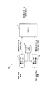
[2-1.全体的な構成]
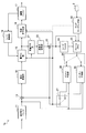
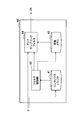
図5は、第1の実施形態に係るEL符号化部1bの構成の一例を示すブロック図である。図5を参照すると、EL符号化部1bは、並び替えバッファ11、減算部13、直交変換部14、量子化部15、可逆符号化部16、蓄積バッファ17、レート制御部18、逆量子化部21、逆直交変換部22、加算部23、ループフィルタ24、フレームメモリ25、セレクタ26及び27、イントラ予測部30、インター予測部35並びにアップサンプリング部40を備える。 <2. Configuration Example of EL Encoding Unit (First Embodiment)>
[2-1. Overall configuration]
FIG. 5 is a block diagram illustrating an example of the configuration of theEL encoding unit 1b according to the first embodiment. Referring to FIG. 5, the EL encoding unit 1b includes a rearrangement buffer 11, a subtraction unit 13, an orthogonal transform unit 14, a quantization unit 15, a lossless encoding unit 16, a storage buffer 17, a rate control unit 18, and an inverse quantization. Unit 21, inverse orthogonal transform unit 22, addition unit 23, loop filter 24, frame memory 25, selectors 26 and 27, intra prediction unit 30, inter prediction unit 35, and upsampling unit 40.
[2-1.全体的な構成]
図5は、第1の実施形態に係るEL符号化部1bの構成の一例を示すブロック図である。図5を参照すると、EL符号化部1bは、並び替えバッファ11、減算部13、直交変換部14、量子化部15、可逆符号化部16、蓄積バッファ17、レート制御部18、逆量子化部21、逆直交変換部22、加算部23、ループフィルタ24、フレームメモリ25、セレクタ26及び27、イントラ予測部30、インター予測部35並びにアップサンプリング部40を備える。 <2. Configuration Example of EL Encoding Unit (First Embodiment)>
[2-1. Overall configuration]
FIG. 5 is a block diagram illustrating an example of the configuration of the
並び替えバッファ11は、一連の画像データに含まれる画像を並び替える。並び替えバッファ11は、符号化処理に係るGOP(Group of Pictures)構造に応じて画像を並び替えた後、並び替え後の画像データを減算部13、イントラ予測部30、及びインター予測部35へ出力する。
The rearrangement buffer 11 rearranges images included in a series of image data. The rearrangement buffer 11 rearranges the images according to the GOP (Group of Pictures) structure related to the encoding process, and then transmits the rearranged image data to the subtraction unit 13, the intra prediction unit 30, and the inter prediction unit 35. Output.
減算部13には、並び替えバッファ11から入力される画像データ、及び後に説明するイントラ予測部30又はインター予測部35から入力される予測画像データが供給される。減算部13は、並び替えバッファ11から入力される画像データと予測画像データとの差分である予測誤差データを算出し、算出した予測誤差データを直交変換部14へ出力する。
The subtraction unit 13 is supplied with image data input from the rearrangement buffer 11 and predicted image data input from the intra prediction unit 30 or the inter prediction unit 35 described later. The subtraction unit 13 calculates prediction error data that is a difference between the image data input from the rearrangement buffer 11 and the prediction image data, and outputs the calculated prediction error data to the orthogonal transformation unit 14.
直交変換部14は、減算部13から入力される予測誤差データについて直交変換を行う。直交変換部14により実行される直交変換は、例えば、離散コサイン変換(Discrete Cosine Transform:DCT)又はカルーネン・レーベ変換などであってよい。HEVCにおいて、直交変換は、TU(変換単位:Transform Unit)と呼ばれるブロックごとに実行される。TUは、CU(符号化単位:Coding Unit)を分割することにより形成されるブロックであり、TUのサイズは、4×4画素、8×8画素、16×16画素及び32×32画素から適応的に選択される。例えば、高域(高周波帯域)成分を多く含む画像領域において、精細な画像を再現することができるように、より小さいTUサイズが選択されてもよい。また、高域成分をあまり含まない画像領域において、変換係数データの符号量を削減するために、より大きいTUサイズが選択されてもよい。あるTUが高域成分をあまり含まない場合には、当該TUについて直交変換の結果として生成される変換係数データは、ゼロに等しい変換係数を多く含むこととなる。あるTUが高域成分を多く含む場合には、当該TUについて直交変換の結果として生成される変換係数データは、非ゼロの変換係数を多く含むこととなる。TUサイズ及び非ゼロの変換係数の数は、各レイヤにおいて符号化されるパラメータから知ることができる。直交変換部14は、直交変換処理により取得される変換係数データを量子化部15へ出力する。
The orthogonal transform unit 14 performs orthogonal transform on the prediction error data input from the subtraction unit 13. The orthogonal transformation performed by the orthogonal transformation part 14 may be discrete cosine transformation (Discrete Cosine Transform: DCT) or Karoonen-Labe transformation, for example. In HEVC, orthogonal transformation is performed for each block called TU (Transform Unit). A TU is a block formed by dividing a CU (Coding Unit), and the TU size is adaptive from 4 × 4 pixels, 8 × 8 pixels, 16 × 16 pixels, and 32 × 32 pixels. Selected. For example, a smaller TU size may be selected so that a fine image can be reproduced in an image region containing a lot of high-frequency (high-frequency band) components. Also, a larger TU size may be selected in order to reduce the code amount of transform coefficient data in an image region that does not contain much high frequency components. When a certain TU does not contain much high-frequency components, the transform coefficient data generated as a result of the orthogonal transform for the TU includes many transform coefficients equal to zero. When a certain TU contains a lot of high frequency components, the transform coefficient data generated as a result of the orthogonal transform for that TU will contain a lot of non-zero transform coefficients. The TU size and the number of non-zero transform coefficients can be known from parameters encoded in each layer. The orthogonal transform unit 14 outputs transform coefficient data acquired by the orthogonal transform process to the quantization unit 15.
量子化部15には、直交変換部14から入力される変換係数データ、及び後に説明するレート制御部18からのレート制御信号が供給される。レート制御信号は、ブロックごとの各色成分についての量子化パラメータを特定する。量子化行列(スケーリングリストともいう)もまた特定され得る。量子化行列は、異なるTUサイズ、色成分(Y/Cr/Cb)及び予測モード(イントラ/インター)の各々について予め定義され得る。量子化部15は、レート制御信号に従って決定される量子化ステップで変換係数データを量子化する。典型的には、量子化パラメータが大きい場合、変換係数データの量子化誤差も大きくなる。この場合、変換係数データに含まれる高域成分は、低域成分と比較して、より失われ易い。量子化パラメータの値は、各レイヤにおいて符号化されるパラメータから知ることができる。量子化行列が使用される場合、量子化部15は、変換係数データのブロックサイズ、色成分、及び対応する予測モード(即ち、予測誤差データを算出する際に使用された予測モード)に応じて、使用すべき量子化行列を切り替える。量子化部15は、量子化後の変換係数データ(以下、量子化データという)を可逆符号化部16及び逆量子化部21へ出力する。
The quantization unit 15 is supplied with transform coefficient data input from the orthogonal transform unit 14 and a rate control signal from the rate control unit 18 described later. The rate control signal specifies a quantization parameter for each color component for each block. A quantization matrix (also referred to as a scaling list) can also be specified. The quantization matrix can be predefined for each of the different TU sizes, color components (Y / Cr / Cb) and prediction modes (intra / inter). The quantization unit 15 quantizes the transform coefficient data in a quantization step determined according to the rate control signal. Typically, when the quantization parameter is large, the quantization error of the transform coefficient data also increases. In this case, the high frequency component included in the transform coefficient data is more easily lost than the low frequency component. The value of the quantization parameter can be known from the parameters encoded in each layer. When a quantization matrix is used, the quantization unit 15 depends on the block size of the transform coefficient data, the color component, and the corresponding prediction mode (that is, the prediction mode used when calculating the prediction error data). , Switch the quantization matrix to be used. The quantization unit 15 outputs the quantized transform coefficient data (hereinafter referred to as quantized data) to the lossless encoding unit 16 and the inverse quantization unit 21.
なお、変換係数データの値は、イントラ予測又はインター予測の予測誤差に依存する(変換係数データは、空間領域の予測誤差を周波数領域に変換した結果である)。そして、多くの場合、イントラ予測の参照ブロックは予測対象ブロックとは異なるテクスチャ(同じ時刻の近傍のテクスチャ)を有するのに対し、インター予測の参照ブロックは予測対象ブロックと同じテクスチャ(別の時刻の同じ被写体のテクスチャ)を有する。そのため、イントラ予測の予測誤差と、インター予測の予測誤差とは、異なる値の傾向を有する。これが、上述したようにイントラ予測とインター予測とで異なる量子化行列が定義される理由である。しかし、イントラ予測の1つのモードとして扱われるイントラBL予測では、エンハンスメントレイヤの予測対象ブロックと同じ位置の(即ち、同じテクスチャを有する)ベースレイヤの参照ブロックが使用される。従って、量子化部15は、イントラ予測モードの中でも特にイントラBL予測に基づいて予測誤差が算出された場合には、例外的にインター予測モードのために定義される量子化行列を用いて、変換係数データを量子化してもよい。それにより、インターレイヤ予測後の量子化に起因する意図しない画質の劣化を回避することができる。
Note that the value of the transform coefficient data depends on the prediction error of the intra prediction or the inter prediction (the transform coefficient data is a result of converting the prediction error in the spatial domain into the frequency domain). In many cases, the reference block for intra prediction has a different texture (a texture near the same time) from the prediction target block, whereas the reference block for inter prediction has the same texture (a different time) as the prediction target block. Have the same subject texture). Therefore, the prediction error of intra prediction and the prediction error of inter prediction have different values. This is the reason why different quantization matrices are defined for intra prediction and inter prediction as described above. However, in intra BL prediction treated as one mode of intra prediction, a reference block in the base layer at the same position as the prediction target block in the enhancement layer (that is, having the same texture) is used. Therefore, the quantization unit 15 uses the quantization matrix defined for the inter prediction mode as an exception when the prediction error is calculated based on the intra BL prediction among the intra prediction modes. The coefficient data may be quantized. Thereby, it is possible to avoid unintended image quality degradation due to quantization after inter-layer prediction.
可逆符号化部16は、量子化部15から入力される量子化データについて可逆符号化処理を行うことにより、エンハンスメントレイヤの符号化ストリームを生成する。また、可逆符号化部16は、符号化ストリームを復号する際に参照される様々なパラメータを符号化して、符号化されたパラメータを符号化ストリームのヘッダ領域に挿入する。可逆符号化部16により符号化されるパラメータは、後に説明するイントラ予測に関する情報及びインター予測に関する情報を含み得る。第1の実施例では、高域成分の強さに関連するパラメータもまた、各レイヤにおいて符号化され得る。第2の実施例では、アップサンプリングフィルタのブロックごとの最適なフィルタ構成を示すフィルタ構成情報が符号化され得る。そして、可逆符号化部16は、生成した符号化ストリームを蓄積バッファ17へ出力する。
The lossless encoding unit 16 performs a lossless encoding process on the quantized data input from the quantization unit 15 to generate an enhancement layer encoded stream. In addition, the lossless encoding unit 16 encodes various parameters referred to when decoding the encoded stream, and inserts the encoded parameters into the header area of the encoded stream. The parameters encoded by the lossless encoding unit 16 may include information related to intra prediction and information related to inter prediction, which will be described later. In the first embodiment, the parameters related to the strength of the high frequency component can also be encoded in each layer. In the second embodiment, filter configuration information indicating an optimal filter configuration for each block of the upsampling filter can be encoded. Then, the lossless encoding unit 16 outputs the generated encoded stream to the accumulation buffer 17.
蓄積バッファ17は、可逆符号化部16から入力される符号化ストリームを半導体メモリなどの記憶媒体を用いて一時的に蓄積する。そして、蓄積バッファ17は、蓄積した符号化ストリームを、伝送路の帯域に応じたレートで、図示しない伝送部(例えば、通信インタフェース又は周辺機器との接続インタフェースなど)へ出力する。
The accumulation buffer 17 temporarily accumulates the encoded stream input from the lossless encoding unit 16 using a storage medium such as a semiconductor memory. Then, the accumulation buffer 17 outputs the accumulated encoded stream to a transmission unit (not shown) (for example, a communication interface or a connection interface with a peripheral device) at a rate corresponding to the bandwidth of the transmission path.
レート制御部18は、蓄積バッファ17の空き容量を監視する。そして、レート制御部18は、蓄積バッファ17の空き容量に応じてレート制御信号を生成し、生成したレート制御信号を量子化部15へ出力する。例えば、レート制御部18は、蓄積バッファ17の空き容量が少ない時には、量子化データのビットレートを低下させるためのレート制御信号を生成する。また、例えば、レート制御部18は、蓄積バッファ17の空き容量が十分大きい時には、量子化データのビットレートを高めるためのレート制御信号を生成する。
The rate control unit 18 monitors the free capacity of the accumulation buffer 17. Then, the rate control unit 18 generates a rate control signal according to the free capacity of the accumulation buffer 17 and outputs the generated rate control signal to the quantization unit 15. For example, the rate control unit 18 generates a rate control signal for reducing the bit rate of the quantized data when the free capacity of the storage buffer 17 is small. For example, when the free capacity of the accumulation buffer 17 is sufficiently large, the rate control unit 18 generates a rate control signal for increasing the bit rate of the quantized data.
逆量子化部21、逆直交変換部22及び加算部23は、ローカルデコーダを構成する。逆量子化部21は、量子化部15により使用されたものと同じ量子化ステップで、エンハンスメントレイヤの量子化データを逆量子化し、変換係数データを復元する。逆量子化部21は、ベースレイヤの画像を参照画像として使用するイントラBL予測により予測誤差データが生成された場合において、量子化行列が使用されるときは、インター予測モードのために定義される量子化行列を用いてエンハンスメントレイヤの量子化データを逆量子化することにより、変換係数データを復元してもよい。そして、逆量子化部21は、復元した変換係数データを逆直交変換部22へ出力する。
The inverse quantization unit 21, the inverse orthogonal transform unit 22, and the addition unit 23 constitute a local decoder. The inverse quantization unit 21 performs the same quantization step as that used by the quantization unit 15 and inversely quantizes the enhancement layer quantization data to restore the transform coefficient data. The inverse quantization unit 21 is defined for the inter prediction mode when the prediction matrix is used when the prediction error data is generated by the intra-BL prediction using the base layer image as the reference image. The transform coefficient data may be restored by inversely quantizing the enhancement layer quantized data using the quantization matrix. Then, the inverse quantization unit 21 outputs the restored transform coefficient data to the inverse orthogonal transform unit 22.
逆直交変換部22は、逆量子化部21から入力される変換係数データについて逆直交変換処理を行うことにより、予測誤差データを復元する。直交変換と同様、逆直交変換は、TUごとに実行される。そして、逆直交変換部22は、復元した予測誤差データを加算部23へ出力する。
The inverse orthogonal transform unit 22 restores the prediction error data by performing an inverse orthogonal transform process on the transform coefficient data input from the inverse quantization unit 21. Similar to the orthogonal transform, the inverse orthogonal transform is performed for each TU. Then, the inverse orthogonal transform unit 22 outputs the restored prediction error data to the addition unit 23.
加算部23は、逆直交変換部22から入力される復元された予測誤差データとイントラ予測部30又はインター予測部35から入力される予測画像データとを加算することにより、復号画像データ(エンハンスメントレイヤのリコンストラクト画像)を生成する。そして、加算部23は、生成した復号画像データをループフィルタ24及びフレームメモリ25へ出力する。
The adding unit 23 adds decoded image error data (enhancement layer) by adding the restored prediction error data input from the inverse orthogonal transform unit 22 and the predicted image data input from the intra prediction unit 30 or the inter prediction unit 35. Of the reconstructed image). Then, the adder 23 outputs the generated decoded image data to the loop filter 24 and the frame memory 25.
ループフィルタ24は、画質の向上を目的とするフィルタ群を含む。デブロックフィルタ(DF)は、画像の符号化時に生じるブロック歪みを軽減するフィルタである。サンプル適応オフセット(SAO)フィルタは、各画素値に適応的に決定されるオフセット値を加えるフィルタである。典型的には、オフセット種別として、LCU(Largest Coding Unit)ごとに、バンドオフセット、エッジオフセット及びオフセットなし、という3種類の種別が選択可能である。エッジオフセットが選択された場合、エッジ周辺の画素の画素値にオフセットが付加され、不要な高域成分であるモスキート歪みが除去される。バンドオフセットが選択された場合、特定の範囲の輝度成分にオフセットが付加され、平坦な画像領域の画質が改善される。適応ループフィルタ(ALF)は、SAO後の画像と原画像との誤差を最小化するフィルタである。ループフィルタ24は、加算部23から入力される復号画像データをフィルタリングし、フィルタリング後の復号画像データをフレームメモリ25へ出力する。
The loop filter 24 includes a filter group for the purpose of improving the image quality. The deblocking filter (DF) is a filter that reduces block distortion that occurs when an image is encoded. A sample adaptive offset (SAO) filter is a filter that adds an adaptively determined offset value to each pixel value. Typically, as an offset type, for each LCU (Largest Coding Unit), three types of band offset, edge offset, and no offset can be selected. When the edge offset is selected, an offset is added to the pixel values of pixels around the edge, and mosquito distortion, which is an unnecessary high-frequency component, is removed. When the band offset is selected, the offset is added to the luminance component in a specific range, and the image quality of the flat image area is improved. The adaptive loop filter (ALF) is a filter that minimizes an error between the image after SAO and the original image. The loop filter 24 filters the decoded image data input from the adding unit 23 and outputs the decoded image data after filtering to the frame memory 25.
フレームメモリ25は、加算部23から入力されるエンハンスメントレイヤの復号画像データ、ループフィルタ24から入力されるエンハンスメントレイヤのフィルタリング後の復号画像データ、及びアップサンプリング部40から入力されるベースレイヤの参照画像データを記憶媒体を用いて記憶する。
The frame memory 25 includes enhancement layer decoded image data input from the adder 23, enhancement layer filtered image data input from the loop filter 24, and base layer reference image input from the upsampling unit 40. Data is stored using a storage medium.
セレクタ26は、イントラ予測のために使用されるフィルタリング前の復号画像データをフレームメモリ25から読み出し、読み出した復号画像データを参照画像データとしてイントラ予測部30に供給する。また、セレクタ26は、インター予測のために使用されるフィルタリング後の復号画像データをフレームメモリ25から読み出し、読み出した復号画像データを参照画像データとしてインター予測部35に供給する。さらに、イントラ予測部30又はインター予測部35においてインターレイヤ予測が実行される場合、セレクタ26は、ベースレイヤの参照画像データをイントラ予測部30又はインター予測部35へ供給する。
The selector 26 reads out the decoded image data before filtering used for intra prediction from the frame memory 25 and supplies the read decoded image data to the intra prediction unit 30 as reference image data. In addition, the selector 26 reads out the decoded image data after filtering used for inter prediction from the frame memory 25 and supplies the read out decoded image data to the inter prediction unit 35 as reference image data. Further, when inter layer prediction is performed in the intra prediction unit 30 or the inter prediction unit 35, the selector 26 supplies the reference image data of the base layer to the intra prediction unit 30 or the inter prediction unit 35.
セレクタ27は、イントラ予測モードにおいて、イントラ予測部30から出力されるイントラ予測の結果としての予測画像データを減算部13へ出力すると共に、イントラ予測に関する情報を可逆符号化部16へ出力する。また、セレクタ27は、インター予測モードにおいて、インター予測部35から出力されるインター予測の結果としての予測画像データを減算部13へ出力すると共に、インター予測に関する情報を可逆符号化部16へ出力する。イントラ予測に関する情報は、量子化行列の切替えのために、量子化部15及び逆量子化部21へ出力されてもよい。セレクタ27は、イントラ予測モードとインター予測モードとを、コスト関数値の大きさに応じて切り替える。
In the intra prediction mode, the selector 27 outputs predicted image data as a result of the intra prediction output from the intra prediction unit 30 to the subtraction unit 13 and outputs information related to the intra prediction to the lossless encoding unit 16. Further, in the inter prediction mode, the selector 27 outputs predicted image data as a result of the inter prediction output from the inter prediction unit 35 to the subtraction unit 13 and outputs information related to the inter prediction to the lossless encoding unit 16. . Information regarding intra prediction may be output to the quantization unit 15 and the inverse quantization unit 21 for switching of the quantization matrix. The selector 27 switches between the intra prediction mode and the inter prediction mode according to the size of the cost function value.
イントラ予測部30は、エンハンスメントレイヤの原画像データ及び復号画像データに基づいて、HEVCのPU(予測単位:Prediction Unit)ごとにイントラ予測処理を行う。例えば、イントラ予測部30は、予測モードセット内の各候補モードによる予測結果を所定のコスト関数を用いて評価する。次に、イントラ予測部30は、コスト関数値が最小となる予測モード、即ち圧縮率が最も高くなる予測モードを、最適な予測モードとして選択する。また、イントラ予測部30は、当該最適な予測モードに従ってエンハンスメントレイヤの予測画像データを生成する。イントラ予測部30は、エンハンスメントレイヤにおける予測モードセットに、インターレイヤ予測の一種であるイントラBL予測を含めてもよい。イントラBL予測では、エンハンスメントレイヤ内の予測対象ブロックに対応するベースレイヤ内のコロケーテッドブロックが参照ブロックとして使用され、当該参照ブロックの復号画像に基づいて予測画像が生成される。また、イントラ予測部30は、インターレイヤ予測の一種であるイントラ残差予測を含めてもよい。イントラ残差予測では、ベースレイヤ内のコロケーテッドブロックである参照ブロックの予測誤差画像に基づいてイントラ予測の予測誤差が予測され、予測された予測誤差の加算された予測画像が生成される(式(2)の右辺の第1項及び第2項参照)。イントラ予測部30は、モード依存イントラ平滑化(Mode-dependent Intra Smoothing)の手法に従い、特定のPUサイズとイントラ予測モードとの組合せについて、参照画像データに平滑化フィルタ(smoothing filter)を適用してもよい。平滑化フィルタは、典型的には3タップのタップ数を有し(フィルタ係数は[1,2,1]/4)、平滑化フィルタが適用されるブロックでは高域成分は失われ易い。イントラ予測部30は、選択した最適な予測モードを表す予測モード情報を含むイントラ予測に関する情報、コスト関数値、及び予測画像データを、セレクタ27へ出力する。
The intra prediction unit 30 performs intra prediction processing for each HEVC PU (Prediction Unit) based on the original image data and decoded image data of the enhancement layer. For example, the intra prediction unit 30 evaluates the prediction result of each candidate mode in the prediction mode set using a predetermined cost function. Next, the intra prediction unit 30 selects the prediction mode with the smallest cost function value, that is, the prediction mode with the highest compression rate, as the optimum prediction mode. The intra prediction unit 30 generates enhancement layer predicted image data according to the optimal prediction mode. The intra prediction unit 30 may include intra BL prediction, which is a type of inter layer prediction, in the prediction mode set in the enhancement layer. In intra BL prediction, a collocated block in the base layer corresponding to a prediction target block in the enhancement layer is used as a reference block, and a prediction image is generated based on a decoded image of the reference block. Further, the intra prediction unit 30 may include intra residual prediction that is a kind of inter-layer prediction. In the intra residual prediction, a prediction error of an intra prediction is predicted based on a prediction error image of a reference block that is a collocated block in a base layer, and a prediction image in which the predicted prediction error is added is generated ( (Refer to the first and second terms on the right side of Equation (2)). The intra prediction unit 30 applies a smoothing filter (smoothing filter) to the reference image data for a combination of a specific PU size and an intra prediction mode according to a mode-dependent intra smoothing technique. Also good. The smoothing filter typically has a tap number of 3 taps (filter coefficients are [1, 2, 1] / 4), and a high frequency component is easily lost in a block to which the smoothing filter is applied. The intra prediction unit 30 outputs information related to intra prediction including prediction mode information representing the selected optimal prediction mode, cost function values, and predicted image data to the selector 27.
インター予測部35は、エンハンスメントレイヤの原画像データ及び復号画像データに基づいて、HEVCのPUごとにインター予測処理を行う。例えば、インター予測部35は、予測モードセット内の各候補モードによる予測結果を所定のコスト関数を用いて評価する。次に、インター予測部35は、コスト関数値が最小となる予測モード、即ち圧縮率が最も高くなる予測モードを、最適な予測モードとして選択する。また、インター予測部35は、当該最適な予測モードに従ってエンハンスメントレイヤの予測画像データを生成する。HEVCのインター予測では、特にBピクチャにおいて、参照方向としてL0予測、L1予測及び双予測(B-Prediction)がPUごとに選択可能である。双予測には2つの参照ブロックを平均する処理が含まれるため、双予測が選択されるブロックでは高域成分は失われ易い。インター予測部35は、エンハンスメントレイヤにおける予測モードセットに、インターレイヤ予測の一種であるインター残差予測を含めてもよい。インター残差予測では、ベースレイヤ内のコロケーテッドブロックである参照ブロックの予測誤差画像に基づいてインター予測の予測誤差が予測され、予測された予測誤差の加算された予測画像が生成される(式(2)の右辺の第1項及び第2項参照)。インター予測部35は、選択した最適な予測モードを表す予測モード情報と動き情報とを含むインター予測に関する情報、コスト関数値、及び予測画像データを、セレクタ27へ出力する。
The inter prediction unit 35 performs inter prediction processing for each PU of HEVC based on the original image data and decoded image data of the enhancement layer. For example, the inter prediction unit 35 evaluates the prediction result of each candidate mode in the prediction mode set using a predetermined cost function. Next, the inter prediction unit 35 selects a prediction mode with the smallest cost function value, that is, a prediction mode with the highest compression rate, as the optimum prediction mode. Further, the inter prediction unit 35 generates enhancement layer predicted image data according to the optimal prediction mode. In HEVC inter prediction, particularly in a B picture, L0 prediction, L1 prediction, and bi-prediction (B-Prediction) can be selected for each PU as reference directions. Since bi-prediction includes the process of averaging two reference blocks, high-frequency components are likely to be lost in blocks for which bi-prediction is selected. The inter prediction unit 35 may include inter residual prediction, which is a type of inter layer prediction, in the prediction mode set in the enhancement layer. In inter residual prediction, a prediction error of inter prediction is predicted based on a prediction error image of a reference block that is a collocated block in a base layer, and a prediction image in which the predicted prediction error is added is generated ( (Refer to the first and second terms on the right side of Equation (2)). The inter prediction unit 35 outputs information about the inter prediction including the prediction mode information representing the selected optimal prediction mode and the motion information, the cost function value, and the prediction image data to the selector 27.
アップサンプリング部40は、共通メモリ2によりバッファリングされるベースレイヤの画像を、ベースレイヤとエンハンスメントレイヤとの間の解像度比に従ってアップサンプリングする。アップサンプリング部40によりアップサンプリングされた画像は、フレームメモリ25に格納され、イントラ予測部30又はインター予測部35により、インターレイヤ予測において参照画像として使用され得る。次項で説明する第1の実施例において、アップサンプリング部40は、アップサンプリングフィルタのフィルタ構成を、ブロックごとの高域成分の強さに応じて切り替える。アップサンプリング部40は、ブロックごとの高域成分の強さに加えて、ピクチャタイプに応じてアップサンプリングフィルタのフィルタ構成を切り替えてもよい。なお、以下の説明では、アップサンプリング部40がブロックごとの高域成分の強さを判定するために使用するパラメータを、高域成分パラメータという。次項では、高域成分パラメータのいくつかの例も示される。その次の項で説明する第2の実施例において、アップサンプリング部40は、アップサンプリングフィルタの最適なフィルタ構成をブロックごとに切り替え、各ブロックに適用したフィルタ構成に対応するフィルタ構成情報を可逆符号化部16に符号化させる。
The up-sampling unit 40 up-samples the base layer image buffered by the common memory 2 in accordance with the resolution ratio between the base layer and the enhancement layer. The image upsampled by the upsampling unit 40 is stored in the frame memory 25 and can be used as a reference image in inter-layer prediction by the intra prediction unit 30 or the inter prediction unit 35. In the first embodiment described in the next section, the upsampling unit 40 switches the filter configuration of the upsampling filter according to the strength of the high frequency component for each block. The upsampling unit 40 may switch the filter configuration of the upsampling filter according to the picture type in addition to the strength of the high frequency component for each block. In the following description, a parameter used by the upsampling unit 40 to determine the strength of the high frequency component for each block is referred to as a high frequency component parameter. In the next section, some examples of high-frequency component parameters are also shown. In the second embodiment described in the next section, the upsampling unit 40 switches the optimum filter configuration of the upsampling filter for each block, and sets the filter configuration information corresponding to the filter configuration applied to each block as a lossless code. The encoding unit 16 performs encoding.
[2-2.アップサンプリング部(第1の実施例)]
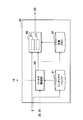
図6は、第1の実施例に係るアップサンプリング部40の構成の一例を示すブロック図である。図6を参照すると、アップサンプリング部40は、シンタックスバッファ41、フィルタ制御部42、係数メモリ43及びアップサンプリングフィルタ44を有する。 [2-2. Upsampling unit (first embodiment)]
FIG. 6 is a block diagram illustrating an example of the configuration of theupsampling unit 40 according to the first embodiment. Referring to FIG. 6, the upsampling unit 40 includes a syntax buffer 41, a filter control unit 42, a coefficient memory 43, and an upsampling filter 44.
図6は、第1の実施例に係るアップサンプリング部40の構成の一例を示すブロック図である。図6を参照すると、アップサンプリング部40は、シンタックスバッファ41、フィルタ制御部42、係数メモリ43及びアップサンプリングフィルタ44を有する。 [2-2. Upsampling unit (first embodiment)]
FIG. 6 is a block diagram illustrating an example of the configuration of the
(1)シンタックスバッファ
シンタックスバッファ41は、フィルタ制御部42がアップサンプリングを制御する際に使用するパラメータを記憶するバッファである。例えば、シンタックスバッファ41は、ベースレイヤ画像とエンハンスメントレイヤ画像との間の予め決定される解像度比を記憶する。解像度比は、可逆符号化部16により符号化され、VPS(Video Parameter Set)、又はエンハンスメントレイヤのSPS(Sequence Parameter Set)若しくはPPS(Picture Parameter Set)に挿入され得る。また、シンタックスバッファ41は、ベースレイヤのブロックごとの高域成分の強さに関連する高域成分パラメータを記憶する。高域成分パラメータは、例えば、BL符号化部1aから共通メモリ2を介して取得されてもよい。また、シンタックスバッファ41は、フィルタ構成の決定のためにピクチャタイプが参照される場合には、各ピクチャのピクチャタイプを記憶してもよい。 (1) Syntax Buffer Thesyntax buffer 41 is a buffer that stores parameters used when the filter control unit 42 controls upsampling. For example, the syntax buffer 41 stores a predetermined resolution ratio between the base layer image and the enhancement layer image. The resolution ratio is encoded by the lossless encoding unit 16 and can be inserted into VPS (Video Parameter Set), or SPS (Sequence Parameter Set) or PPS (Picture Parameter Set) of the enhancement layer. Further, the syntax buffer 41 stores a high frequency component parameter related to the strength of the high frequency component for each block of the base layer. The high frequency component parameter may be acquired from the BL encoding unit 1a via the common memory 2, for example. Further, the syntax buffer 41 may store the picture type of each picture when the picture type is referred to determine the filter configuration.
シンタックスバッファ41は、フィルタ制御部42がアップサンプリングを制御する際に使用するパラメータを記憶するバッファである。例えば、シンタックスバッファ41は、ベースレイヤ画像とエンハンスメントレイヤ画像との間の予め決定される解像度比を記憶する。解像度比は、可逆符号化部16により符号化され、VPS(Video Parameter Set)、又はエンハンスメントレイヤのSPS(Sequence Parameter Set)若しくはPPS(Picture Parameter Set)に挿入され得る。また、シンタックスバッファ41は、ベースレイヤのブロックごとの高域成分の強さに関連する高域成分パラメータを記憶する。高域成分パラメータは、例えば、BL符号化部1aから共通メモリ2を介して取得されてもよい。また、シンタックスバッファ41は、フィルタ構成の決定のためにピクチャタイプが参照される場合には、各ピクチャのピクチャタイプを記憶してもよい。 (1) Syntax Buffer The
(2)フィルタ制御部
フィルタ制御部42は、画像のブロックごとに、アップサンプリングフィルタ44のフィルタ構成を高域成分の強さに応じて切り替える。アップサンプリングされる画像は、ベースレイヤの復号画像及び予測誤差画像の一方又は双方であってよい。例えば、フィルタ制御部42は、各ブロックの高域成分の強さに応じて、アップサンプリングフィルタ44のフィルタタップ数をブロックごとに切り替える。典型的には、フィルタ制御部42は、高域成分が強いブロックのフィルタタップ数を、相対的に大きい値に設定する。それにより、高域成分が精細に再現され、画質が維持される。また、フィルタ制御部42は、高域成分が弱いブロックのフィルタタップ数を、相対的に小さい値に設定する。それにより、アップサンプリングの計算コストが抑制される。高域成分が弱いブロックについては、フィルタタップ数が小さくても、顕著な画質の劣化は生じない。フィルタ制御部42は、高域成分の強さに応じて、アップサンプリングフィルタのフィルタ係数をブロックごとに切り替えてもよい。フィルタ係数は、非特許文献2に記載された補間フィルタと同じであってもよく、又は異なってもよい。 (2) Filter Control Unit Thefilter control unit 42 switches the filter configuration of the upsampling filter 44 according to the strength of the high frequency component for each block of the image. The upsampled image may be one or both of a base layer decoded image and a prediction error image. For example, the filter control unit 42 switches the number of filter taps of the upsampling filter 44 for each block according to the strength of the high frequency component of each block. Typically, the filter control unit 42 sets the number of filter taps of a block having a strong high frequency component to a relatively large value. Thereby, the high frequency component is reproduced finely and the image quality is maintained. Further, the filter control unit 42 sets the number of filter taps of a block having a weak high frequency component to a relatively small value. Thereby, the calculation cost of upsampling is suppressed. For blocks with weak high-frequency components, significant image quality degradation does not occur even if the number of filter taps is small. The filter control unit 42 may switch the filter coefficient of the upsampling filter for each block according to the strength of the high frequency component. The filter coefficient may be the same as or different from the interpolation filter described in Non-Patent Document 2.
フィルタ制御部42は、画像のブロックごとに、アップサンプリングフィルタ44のフィルタ構成を高域成分の強さに応じて切り替える。アップサンプリングされる画像は、ベースレイヤの復号画像及び予測誤差画像の一方又は双方であってよい。例えば、フィルタ制御部42は、各ブロックの高域成分の強さに応じて、アップサンプリングフィルタ44のフィルタタップ数をブロックごとに切り替える。典型的には、フィルタ制御部42は、高域成分が強いブロックのフィルタタップ数を、相対的に大きい値に設定する。それにより、高域成分が精細に再現され、画質が維持される。また、フィルタ制御部42は、高域成分が弱いブロックのフィルタタップ数を、相対的に小さい値に設定する。それにより、アップサンプリングの計算コストが抑制される。高域成分が弱いブロックについては、フィルタタップ数が小さくても、顕著な画質の劣化は生じない。フィルタ制御部42は、高域成分の強さに応じて、アップサンプリングフィルタのフィルタ係数をブロックごとに切り替えてもよい。フィルタ係数は、非特許文献2に記載された補間フィルタと同じであってもよく、又は異なってもよい。 (2) Filter Control Unit The
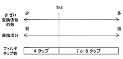
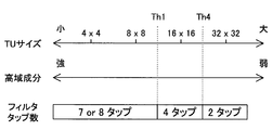
図7Aは、高域成分パラメータとフィルタタップ数との間の関係の第1の例について説明するための説明図である。第1の例において、高域成分パラメータは、TUサイズである。上述したように、HEVCにおいて、TUサイズは、4×4画素、8×8画素、16×16画素又は32×32画素である。TUサイズが小さいほど、ブロック内に高域成分が多く含まれる可能性が高い。そこで、フィルタ制御部42は、例えば、ベースレイヤの対応ブロック(コロケーテッドブロック)のTUサイズを閾値Th1とを比較し、TUサイズが閾値Th1を上回る場合、即ちTUサイズが16×16画素又は32×32画素である場合に、フィルタタップ数を第1の値(例えば、4)に設定する。一方、フィルタ制御部42は、対応ブロックのTUサイズが閾値Th1を下回る場合、即ちTUサイズが4×4画素又は8×8画素である場合に、フィルタタップ数を第1の値よりも大きい第2の値(例えば、7又は8)に設定する。
FIG. 7A is an explanatory diagram for describing a first example of a relationship between a high frequency component parameter and the number of filter taps. In the first example, the high frequency component parameter is a TU size. As described above, in HEVC, the TU size is 4 × 4 pixels, 8 × 8 pixels, 16 × 16 pixels, or 32 × 32 pixels. The smaller the TU size, the higher the possibility that more high frequency components are included in the block. Therefore, for example, the filter control unit 42 compares the TU size of the corresponding block (collocated block) of the base layer with the threshold Th1, and when the TU size exceeds the threshold Th1, that is, the TU size is 16 × 16 pixels or In the case of 32 × 32 pixels, the number of filter taps is set to a first value (for example, 4). On the other hand, when the TU size of the corresponding block is smaller than the threshold Th1, that is, when the TU size is 4 × 4 pixels or 8 × 8 pixels, the filter control unit 42 sets the number of filter taps larger than the first value. Set to a value of 2 (eg, 7 or 8).
なお、TUサイズと同様に高域成分の強さに関連し得るCUサイズ又はPUサイズが、TUサイズの代わりに高域成分パラメータとして使用されてもよい。
Note that the CU size or PU size that can be related to the strength of the high frequency component as well as the TU size may be used as the high frequency component parameter instead of the TU size.
図7Bは、高域成分パラメータとフィルタタップ数との間の関係の第2の例について説明するための説明図である。第2の例において、高域成分パラメータは、量子化パラメータである。上述したように、量子化パラメータが大きい場合には、ブロック内で高域成分が既に失われている可能性が高い。そこで、フィルタ制御部42は、例えば、ベースレイヤの対応ブロックに適用された量子化パラメータを閾値Th2とを比較し、量子化パラメータが閾値Th2を上回る場合、フィルタタップ数を第1の値(例えば、4)に設定する。一方、フィルタ制御部42は、量子化パラメータが閾値Th2を下回る場合、フィルタタップ数を第1の値よりも大きい第2の値(例えば、7又は8)に設定する。
FIG. 7B is an explanatory diagram for describing a second example of the relationship between the high-frequency component parameter and the number of filter taps. In the second example, the high frequency component parameter is a quantization parameter. As described above, when the quantization parameter is large, there is a high possibility that the high frequency component is already lost in the block. Therefore, for example, the filter control unit 42 compares the quantization parameter applied to the corresponding block of the base layer with the threshold Th2, and if the quantization parameter exceeds the threshold Th2, the filter tap number is set to a first value (for example, 4). On the other hand, when the quantization parameter falls below the threshold Th2, the filter control unit 42 sets the number of filter taps to a second value (for example, 7 or 8) that is larger than the first value.
図7Cは、高域成分パラメータとフィルタタップ数との間の関係の第3の例について説明するための説明図である。第3の例において、高域成分パラメータは、非ゼロの変換係数の数である。上述したように、対応ブロックが高域成分を多く含む場合には、当該対応ブロックについて直交変換の結果として生成される変換係数データは、非ゼロの変換係数を多く含むこととなる。そこで、フィルタ制御部42は、例えば、ベースレイヤの対応ブロックの非ゼロの変換係数の数を閾値Th3と比較し、非ゼロの変換係数の数が閾値Th3を下回る場合、フィルタタップ数を第1の値(例えば、4)に設定する。一方、フィルタ制御部42は、非ゼロの変換係数の数が閾値Th3を上回る場合、フィルタタップ数を第1の値よりも大きい第2の値(例えば、7又は8)に設定する。
FIG. 7C is an explanatory diagram for describing a third example of the relationship between the high-frequency component parameter and the number of filter taps. In the third example, the high frequency component parameter is the number of non-zero transform coefficients. As described above, when the corresponding block includes many high frequency components, the transform coefficient data generated as a result of the orthogonal transform for the corresponding block includes many non-zero transform coefficients. Therefore, for example, the filter control unit 42 compares the number of non-zero transform coefficients of the corresponding block of the base layer with the threshold Th3, and if the number of non-zero transform coefficients is lower than the threshold Th3, the filter control unit 42 sets the first filter tap number (For example, 4). On the other hand, when the number of non-zero conversion coefficients exceeds the threshold Th3, the filter control unit 42 sets the number of filter taps to a second value (for example, 7 or 8) that is larger than the first value.
図7Dは、高域成分パラメータとフィルタタップ数との間の関係の第4の例について説明するための説明図である。第4の例において、高域成分パラメータは、インター予測における参照方向情報である。上述したように、対応ブロックのインター予測において双予測が選択された場合には、平均処理によって高域成分が失われている可能性がある。そこで、フィルタ制御部42は、例えば、ベースレイヤの対応ブロックの参照方向情報が双予測を示す場合、フィルタタップ数を第1の値(例えば、4)に設定する。一方、フィルタ制御部42は、参照方向情報が双予測を示さない場合(例えば、L0予測又はL1予測を示す場合)、フィルタタップ数を第1の値よりも大きい第2の値(例えば、7又は8)に設定する。
FIG. 7D is an explanatory diagram for describing a fourth example of the relationship between the high-frequency component parameter and the number of filter taps. In the fourth example, the high frequency component parameter is reference direction information in inter prediction. As described above, when bi-prediction is selected in the inter prediction of the corresponding block, there is a possibility that the high frequency component is lost due to the averaging process. Therefore, for example, when the reference direction information of the corresponding block of the base layer indicates bi-prediction, the filter control unit 42 sets the number of filter taps to a first value (for example, 4). On the other hand, if the reference direction information does not indicate bi-prediction (for example, indicates L0 prediction or L1 prediction), the filter control unit 42 sets the number of filter taps to a second value larger than the first value (for example, 7 Or set to 8).
図7Eは、高域成分パラメータとフィルタタップ数との間の関係の第5の例について説明するための説明図である。第5の例において、高域成分パラメータは、サンプル適応オフセット処理におけるオフセット種別である。上述したように、対応ブロックのサンプル適応オフセット処理においてエッジオフセットが選択された場合には、モスキート歪みの除去と共に高域成分が失われている可能性がある。そこで、フィルタ制御部42は、例えば、ベースレイヤの対応ブロックにおいて選択されたオフセット種別がエッジオフセットを示す場合、フィルタタップ数を第1の値(例えば、4)に設定する。一方、フィルタ制御部42は、オフセット種別がエッジオフセットを示さない場合(例えば、バンドオフセット又はオフセットなしを示す場合)、フィルタタップ数を第1の値よりも大きい第2の値(例えば、7又は8)に設定する。
FIG. 7E is an explanatory diagram for describing a fifth example of the relationship between the high-frequency component parameter and the number of filter taps. In the fifth example, the high frequency component parameter is an offset type in the sample adaptive offset process. As described above, when the edge offset is selected in the sample adaptive offset processing of the corresponding block, there is a possibility that the high frequency component is lost along with the removal of the mosquito distortion. Therefore, for example, when the offset type selected in the corresponding block of the base layer indicates an edge offset, the filter control unit 42 sets the number of filter taps to a first value (for example, 4). On the other hand, when the offset type does not indicate an edge offset (for example, a band offset or no offset), the filter control unit 42 sets the number of filter taps to a second value (for example, 7 or Set to 8).
図7Fは、高域成分パラメータとフィルタタップ数との間の関係の第6の例について説明するための説明図である。第6の例において、高域成分パラメータは、PUサイズ及びイントラ予測モードである。上述したように、対応ブロックのイントラ予測の際に平滑化フィルタが適用された場合には、平滑化と共に高域成分が失われている可能性がある。そこで、フィルタ制御部42は、例えば、対応ブロックのPUサイズと選択されたイントラ予測モードとの組合せに従って対応ブロックに平滑化フィルタが適用されたかを判定し、平滑化フィルタが適用されたブロックのフィルタタップ数を第1の値(例えば、4)に設定する。例えば、8×8画素のPUにおいて対角線方向の角度予測(Angular Prediction)が選択された場合、平滑化フィルタは適用される。一方、フィルタ制御部42は、平滑化フィルタが適用されなかったブロックのフィルタタップ数を第1の値よりも大きい第2の値(例えば、7又は8)に設定する。例えば、4×4画素のPUには平滑化フィルタは適用されない。
FIG. 7F is an explanatory diagram for describing a sixth example of the relationship between the high-frequency component parameter and the number of filter taps. In the sixth example, the high frequency component parameters are the PU size and the intra prediction mode. As described above, when a smoothing filter is applied during intra prediction of a corresponding block, there is a possibility that high frequency components are lost along with smoothing. Therefore, for example, the filter control unit 42 determines whether a smoothing filter has been applied to the corresponding block according to the combination of the PU size of the corresponding block and the selected intra prediction mode, and the filter of the block to which the smoothing filter has been applied. The number of taps is set to a first value (for example, 4). For example, when an angle prediction (Angular Prediction) in a diagonal direction is selected in an 8 × 8 pixel PU, a smoothing filter is applied. On the other hand, the filter control unit 42 sets the number of filter taps of a block to which the smoothing filter is not applied to a second value (for example, 7 or 8) that is larger than the first value. For example, a smoothing filter is not applied to a 4 × 4 pixel PU.
図7Gは、高域成分パラメータとフィルタタップ数との間の関係の第7の例について説明するための説明図である。第7の例において、高域成分パラメータは、第1の例と同様、TUサイズである。第7の例では、フィルタ制御部42は、ベースレイヤの対応ブロックのTUサイズを、閾値Th1及び閾値Th4と比較する。そして、フィルタ制御部42は、例えばTUサイズが32×32画素である場合にはフィルタタップ数を2に、TUサイズが16×16画素である場合にはフィルタタップ数を4に、TUサイズが8×8画素又は4×4画素である場合にはフィルタタップ数を7又は8に設定する。
FIG. 7G is an explanatory diagram for describing a seventh example of the relationship between the high-frequency component parameter and the number of filter taps. In the seventh example, the high frequency component parameter is the TU size as in the first example. In the seventh example, the filter control unit 42 compares the TU size of the corresponding block of the base layer with the threshold Th1 and the threshold Th4. Then, for example, when the TU size is 32 × 32 pixels, the filter control unit 42 sets the number of filter taps to 2, when the TU size is 16 × 16 pixels, the number of filter taps is 4, and the TU size is In the case of 8 × 8 pixels or 4 × 4 pixels, the number of filter taps is set to 7 or 8.
なお、高域成分パラメータとフィルタタップ数との間の関係は、図7A~図7Gの例に限定されない。例えば、上述した閾値Th1~Th4とは異なる閾値が使用されてもよい。また、4タップと7又は8タップとのタップ数の組合せではなく、6タップと12タップとのタップ数の組合せが使用されてもよい。また、タップ数及びフィルタ係数の少なくとも一方を設定するために、2種類以上の高域成分パラメータが任意の組合せで使用されてもよい。
Note that the relationship between the high-frequency component parameter and the number of filter taps is not limited to the examples in FIGS. 7A to 7G. For example, a threshold value different from the above-described threshold values Th1 to Th4 may be used. Further, instead of the combination of the number of taps of 4 taps and 7 or 8 taps, a combination of the number of taps of 6 taps and 12 taps may be used. Further, two or more types of high-frequency component parameters may be used in any combination in order to set at least one of the number of taps and the filter coefficient.
また、フィルタ制御部42は、ブロックごとの適応的なアップサンプリングの制御を、ピクチャタイプに依存して実行してもよい。例えば、フィルタ制御部42は、参照画像のピクチャタイプがBピクチャを示す場合には、高域成分の強さに関わらずアップサンプリングフィルタのタップ数を小さい値に設定し、ピクチャタイプがIピクチャ又はPピクチャを示す場合に、ブロックごとに判定される高域成分の強さに応じて、アップサンプリングフィルタのタップ数を複数の値の間で切り替えてもよい。
Further, the filter control unit 42 may execute adaptive upsampling control for each block depending on the picture type. For example, when the picture type of the reference image indicates B picture, the filter control unit 42 sets the number of taps of the upsampling filter to a small value regardless of the strength of the high frequency component, and the picture type is I picture or When a P picture is shown, the number of taps of the upsampling filter may be switched between a plurality of values according to the strength of the high frequency component determined for each block.
(3)係数メモリ
係数メモリ43は、アップサンプリングフィルタ44により使用される様々なフィルタ係数の候補を記憶するメモリである。係数メモリ43は、例えば、補間される画素位置とタップ数との各組合せについて、それぞれフィルタ係数のセットを記憶する。係数メモリ43により記憶されるフィルタ係数のセットは、フィルタ制御部42による設定に従って、アップサンプリングフィルタ44により読み出される。なお、フィルタ係数は、フィルタ制御部42により動的に計算されてもよい。 (3) Coefficient Memory Thecoefficient memory 43 is a memory that stores various filter coefficient candidates used by the upsampling filter 44. For example, the coefficient memory 43 stores a set of filter coefficients for each combination of the pixel position to be interpolated and the number of taps. The set of filter coefficients stored in the coefficient memory 43 is read out by the upsampling filter 44 according to the setting by the filter control unit 42. The filter coefficient may be dynamically calculated by the filter control unit 42.
係数メモリ43は、アップサンプリングフィルタ44により使用される様々なフィルタ係数の候補を記憶するメモリである。係数メモリ43は、例えば、補間される画素位置とタップ数との各組合せについて、それぞれフィルタ係数のセットを記憶する。係数メモリ43により記憶されるフィルタ係数のセットは、フィルタ制御部42による設定に従って、アップサンプリングフィルタ44により読み出される。なお、フィルタ係数は、フィルタ制御部42により動的に計算されてもよい。 (3) Coefficient Memory The
(4)アップサンプリングフィルタ
アップサンプリングフィルタ44は、フィルタ制御部42による制御の下、ベースレイヤよりも空間解像度の高いエンハンスメントレイヤの画像をローカルデコードする際に参照されるベースレイヤの画像をアップサンプリングする。アップサンプリングフィルタ44によりアップサンプリングされる画像は、ベースレイヤの復号画像及び予測誤差画像の一方又は双方であってよい。より具体的には、アップサンプリングフィルタ44は、共通メモリ2から取得されるベースレイヤの画像について、解像度比と、ブロックごとに高域成分の強さに応じて設定されるフィルタ構成とを識別する。そして、アップサンプリングフィルタ44は、解像度比に応じて順に走査される補間画素の各々について、係数メモリ43から取得されるフィルタ係数でベースレイヤの画像をフィルタリングすることにより、補間画素値を算出する。それにより、参照ブロックとして使用されるベースレイヤの画像の空間解像度が、エンハンスメントレイヤと同等の解像度まで高められる。アップサンプリングフィルタ44は、アップサンプリング後の参照画像データをフレームメモリ25へ出力する。 (4) Up-sampling filter The up-sampling filter 44 up-samples the base layer image referred to when locally decoding an enhancement layer image having a spatial resolution higher than that of the base layer under the control of the filter control unit 42. . The image up-sampled by the up-sampling filter 44 may be one or both of a base layer decoded image and a prediction error image. More specifically, the upsampling filter 44 identifies the resolution ratio and the filter configuration set according to the strength of the high frequency component for each block for the base layer image acquired from the common memory 2. . Then, the upsampling filter 44 calculates the interpolation pixel value by filtering the base layer image with the filter coefficient acquired from the coefficient memory 43 for each of the interpolation pixels scanned in order according to the resolution ratio. Thereby, the spatial resolution of the image of the base layer used as the reference block is increased to a resolution equivalent to that of the enhancement layer. The upsampling filter 44 outputs the reference image data after upsampling to the frame memory 25.
アップサンプリングフィルタ44は、フィルタ制御部42による制御の下、ベースレイヤよりも空間解像度の高いエンハンスメントレイヤの画像をローカルデコードする際に参照されるベースレイヤの画像をアップサンプリングする。アップサンプリングフィルタ44によりアップサンプリングされる画像は、ベースレイヤの復号画像及び予測誤差画像の一方又は双方であってよい。より具体的には、アップサンプリングフィルタ44は、共通メモリ2から取得されるベースレイヤの画像について、解像度比と、ブロックごとに高域成分の強さに応じて設定されるフィルタ構成とを識別する。そして、アップサンプリングフィルタ44は、解像度比に応じて順に走査される補間画素の各々について、係数メモリ43から取得されるフィルタ係数でベースレイヤの画像をフィルタリングすることにより、補間画素値を算出する。それにより、参照ブロックとして使用されるベースレイヤの画像の空間解像度が、エンハンスメントレイヤと同等の解像度まで高められる。アップサンプリングフィルタ44は、アップサンプリング後の参照画像データをフレームメモリ25へ出力する。 (4) Up-sampling filter The up-
[2-3.アップサンプリング部(第2の実施例)]
図8は、第2の実施例に係るアップサンプリング部40の構成の一例を示すブロック図である。図8を参照すると、アップサンプリング部40は、シンタックスバッファ41、フィルタ制御部46、係数メモリ47及びアップサンプリングフィルタ48を有する。 [2-3. Upsampling unit (second embodiment)]
FIG. 8 is a block diagram illustrating an example of the configuration of theupsampling unit 40 according to the second embodiment. Referring to FIG. 8, the upsampling unit 40 includes a syntax buffer 41, a filter control unit 46, a coefficient memory 47, and an upsampling filter 48.
図8は、第2の実施例に係るアップサンプリング部40の構成の一例を示すブロック図である。図8を参照すると、アップサンプリング部40は、シンタックスバッファ41、フィルタ制御部46、係数メモリ47及びアップサンプリングフィルタ48を有する。 [2-3. Upsampling unit (second embodiment)]
FIG. 8 is a block diagram illustrating an example of the configuration of the
(1)シンタックスバッファ
シンタックスバッファ41は、フィルタ制御部46がアップサンプリングを制御する際に使用するパラメータを記憶するバッファである。第2の実施例において、シンタックスバッファ41は、ベースレイヤ画像とエンハンスメントレイヤ画像との間の予め決定される解像度比を記憶する。解像度比は、可逆符号化部16により符号化され、VPS、又はエンハンスメントレイヤのSPS若しくはPPSに挿入され得る。シンタックスバッファ41は、フィルタ構成の決定のためにピクチャタイプが参照される場合には、各ピクチャのピクチャタイプを記憶してもよい。 (1) Syntax Buffer Thesyntax buffer 41 is a buffer that stores parameters used when the filter control unit 46 controls upsampling. In the second embodiment, the syntax buffer 41 stores a predetermined resolution ratio between the base layer image and the enhancement layer image. The resolution ratio is encoded by the lossless encoding unit 16 and can be inserted into the VPS or the enhancement layer SPS or PPS. The syntax buffer 41 may store the picture type of each picture when the picture type is referred to determine the filter configuration.
シンタックスバッファ41は、フィルタ制御部46がアップサンプリングを制御する際に使用するパラメータを記憶するバッファである。第2の実施例において、シンタックスバッファ41は、ベースレイヤ画像とエンハンスメントレイヤ画像との間の予め決定される解像度比を記憶する。解像度比は、可逆符号化部16により符号化され、VPS、又はエンハンスメントレイヤのSPS若しくはPPSに挿入され得る。シンタックスバッファ41は、フィルタ構成の決定のためにピクチャタイプが参照される場合には、各ピクチャのピクチャタイプを記憶してもよい。 (1) Syntax Buffer The
(2)フィルタ制御部
フィルタ制御部46は、画像のブロックごとに、復号の際に使用されるべきアップサンプリングフィルタ48のフィルタ構成を切り替える。アップサンプリングされる画像は、ベースレイヤの復号画像及び予測誤差画像の一方又は双方であってよい。フィルタ制御部46は、例えば、各ブロックについて、複数のフィルタ構成でアップサンプリングフィルタ48にそれぞれアップサンプリング画像を生成させる。フィルタ構成は、フィルタタップ数及びフィルタ係数の少なくとも一方を含み得る。フィルタ構成ごとのアップサンプリング画像は、フレームメモリ25に格納される。そして、フィルタ制御部46は、イントラ予測部30によるイントラ予測又はインター予測部35によるインター予測の結果に基づいて最適なフィルタ構成を選択する。最適なフィルタ構成とは、典型的には、コスト関数値を最小にするフィルタ構成であってよい。この場合、コスト関数値はPUごとに計算され得るため、フィルタ構成の切替えをPUごとに行うことが有益である。但し、フィルタ制御部46は、LCU、CU又はTUなどの他の単位でフィルタ構成を切り替えてもよい。フィルタ制御部46は、選択したフィルタ構成に対応するフィルタ構成情報を生成し、生成したフィルタ構成情報をブロックごとに可逆符号化部16へ出力する。出力されたフィルタ構成情報は、可逆符号化部16により、エンハンスメントレイヤの符号化ストリームへ符号化される。 (2) Filter Control Unit Thefilter control unit 46 switches the filter configuration of the upsampling filter 48 to be used for decoding for each block of the image. The upsampled image may be one or both of a base layer decoded image and a prediction error image. For example, for each block, the filter control unit 46 causes the upsampling filter 48 to generate an upsampled image with a plurality of filter configurations. The filter configuration may include at least one of the number of filter taps and filter coefficients. The upsampled image for each filter configuration is stored in the frame memory 25. Then, the filter control unit 46 selects an optimal filter configuration based on the result of intra prediction by the intra prediction unit 30 or inter prediction by the inter prediction unit 35. The optimal filter configuration may typically be a filter configuration that minimizes the cost function value. In this case, since the cost function value can be calculated for each PU, it is beneficial to switch the filter configuration for each PU. However, the filter control unit 46 may switch the filter configuration in other units such as LCU, CU, or TU. The filter control unit 46 generates filter configuration information corresponding to the selected filter configuration, and outputs the generated filter configuration information to the lossless encoding unit 16 for each block. The output filter configuration information is encoded into an enhancement layer encoded stream by the lossless encoding unit 16.
フィルタ制御部46は、画像のブロックごとに、復号の際に使用されるべきアップサンプリングフィルタ48のフィルタ構成を切り替える。アップサンプリングされる画像は、ベースレイヤの復号画像及び予測誤差画像の一方又は双方であってよい。フィルタ制御部46は、例えば、各ブロックについて、複数のフィルタ構成でアップサンプリングフィルタ48にそれぞれアップサンプリング画像を生成させる。フィルタ構成は、フィルタタップ数及びフィルタ係数の少なくとも一方を含み得る。フィルタ構成ごとのアップサンプリング画像は、フレームメモリ25に格納される。そして、フィルタ制御部46は、イントラ予測部30によるイントラ予測又はインター予測部35によるインター予測の結果に基づいて最適なフィルタ構成を選択する。最適なフィルタ構成とは、典型的には、コスト関数値を最小にするフィルタ構成であってよい。この場合、コスト関数値はPUごとに計算され得るため、フィルタ構成の切替えをPUごとに行うことが有益である。但し、フィルタ制御部46は、LCU、CU又はTUなどの他の単位でフィルタ構成を切り替えてもよい。フィルタ制御部46は、選択したフィルタ構成に対応するフィルタ構成情報を生成し、生成したフィルタ構成情報をブロックごとに可逆符号化部16へ出力する。出力されたフィルタ構成情報は、可逆符号化部16により、エンハンスメントレイヤの符号化ストリームへ符号化される。 (2) Filter Control Unit The
フィルタ制御部46は、ブロックごとの適応的なアップサンプリングの制御を、ピクチャタイプに依存して実行してもよい。例えば、フィルタ制御部46は、参照画像のピクチャタイプがBピクチャを示す場合には、固定的なフィルタ構成(例えば、より少ないフィルタタップ数)に設定し、ピクチャタイプがIピクチャ又はPピクチャを示す場合に、アップサンプリングフィルタのフィルタ構成を適応的に切り替えてもよい。
The filter control unit 46 may perform adaptive upsampling control for each block depending on the picture type. For example, when the picture type of the reference image indicates a B picture, the filter control unit 46 sets a fixed filter configuration (for example, a smaller number of filter taps), and the picture type indicates an I picture or a P picture. In some cases, the filter configuration of the upsampling filter may be switched adaptively.
(3)係数メモリ
係数メモリ47は、アップサンプリングフィルタ48により使用される様々なフィルタ係数の候補を記憶するメモリである。係数メモリ47は、例えば、補間される画素位置とタップ数との各組合せについて、それぞれフィルタ係数のセットを記憶する。例えば、輝度成分について、第1のフィルタ構成は、7又は8タップのフィルタタップ数、及び動き補償のための補間フィルタと同じフィルタ係数を有し得る。第2のフィルタ構成は、4タップのフィルタタップ数、及びDCTのための補間フィルタと同じフィルタ係数を有し得る。色差成分について、第1のフィルタ構成は、4タップのフィルタタップ数、及び動き補償のための補間フィルタと同じフィルタ係数を有し得る。第2のフィルタ構成は、2タップのフィルタタップ数、及び線形内挿に相当するフィルタ係数を有し得る。係数メモリ47により記憶されるフィルタ係数のセットは、アップサンプリングフィルタ48により読み出される。 (3) Coefficient Memory Thecoefficient memory 47 is a memory that stores various filter coefficient candidates used by the upsampling filter 48. For example, the coefficient memory 47 stores a set of filter coefficients for each combination of the pixel position to be interpolated and the number of taps. For example, for the luminance component, the first filter configuration may have 7 or 8 taps and the same filter coefficients as the interpolation filter for motion compensation. The second filter configuration may have a 4-tap number of filter taps and the same filter coefficients as the interpolation filter for DCT. For the color difference component, the first filter configuration may have a 4-tap number of filter taps and the same filter coefficients as the interpolation filter for motion compensation. The second filter configuration may have a 2-tap number of filter taps and a filter coefficient corresponding to linear interpolation. The set of filter coefficients stored in the coefficient memory 47 is read out by the upsampling filter 48.
係数メモリ47は、アップサンプリングフィルタ48により使用される様々なフィルタ係数の候補を記憶するメモリである。係数メモリ47は、例えば、補間される画素位置とタップ数との各組合せについて、それぞれフィルタ係数のセットを記憶する。例えば、輝度成分について、第1のフィルタ構成は、7又は8タップのフィルタタップ数、及び動き補償のための補間フィルタと同じフィルタ係数を有し得る。第2のフィルタ構成は、4タップのフィルタタップ数、及びDCTのための補間フィルタと同じフィルタ係数を有し得る。色差成分について、第1のフィルタ構成は、4タップのフィルタタップ数、及び動き補償のための補間フィルタと同じフィルタ係数を有し得る。第2のフィルタ構成は、2タップのフィルタタップ数、及び線形内挿に相当するフィルタ係数を有し得る。係数メモリ47により記憶されるフィルタ係数のセットは、アップサンプリングフィルタ48により読み出される。 (3) Coefficient Memory The
(4)アップサンプリングフィルタ
アップサンプリングフィルタ48は、フィルタ制御部46による制御の下、ベースレイヤよりも空間解像度の高いエンハンスメントレイヤの画像をローカルデコードする際に参照されるベースレイヤの画像をアップサンプリングする。アップサンプリングフィルタ48は、異なるフィルタ構成に対応する複数のフィルタ回路F1、F2を有していてもよい。より具体的には、アップサンプリングフィルタ48は、共通メモリ2から取得されるベースレイヤの画像について、解像度比を識別する。そして、アップサンプリングフィルタ48は、解像度比に応じて順に走査される補間画素の各々について、第1のフィルタ構成でベースレイヤの画像をフィルタリングすることにより第1の補間画素値を算出し、及び第2のフィルタ構成でベースレイヤの画像をフィルタリングすることにより第2の補間画素値を算出する。それにより、エンハンスメントレイヤと同等にまで高められた空間解像度を有する2種類のアップサンプリング画像が生成される。アップサンプリングフィルタ48は、複数のフィルタ構成に対応するこれらアップサンプリング画像(アップサンプリング後の参照画像データ)を、それぞれフレームメモリ25へ出力する。なお、あるブロックに適用されるべきフィルタ構成をフィルタ制御部46が予め知っている場合には、アップサンプリングフィルタ48は、当該ブロックについて、単一の当該フィルタ構成に対応するアップサンプリング画像のみを生成してもよい。 (4) Up-sampling filter The up-sampling filter 48 up-samples the base layer image referred to when locally decoding an enhancement layer image having a spatial resolution higher than that of the base layer under the control of the filter control unit 46. . The upsampling filter 48 may include a plurality of filter circuits F1 and F2 corresponding to different filter configurations. More specifically, the upsampling filter 48 identifies the resolution ratio for the base layer image acquired from the common memory 2. Then, the upsampling filter 48 calculates the first interpolation pixel value by filtering the base layer image with the first filter configuration for each of the interpolation pixels that are sequentially scanned according to the resolution ratio, and The second interpolation pixel value is calculated by filtering the base layer image with the filter configuration of 2. Thereby, two types of up-sampled images having a spatial resolution increased to the same level as the enhancement layer are generated. The upsampling filter 48 outputs these upsampled images (reference image data after upsampling) corresponding to a plurality of filter configurations to the frame memory 25, respectively. When the filter control unit 46 knows in advance the filter configuration to be applied to a certain block, the upsampling filter 48 generates only the upsampled image corresponding to the single relevant filter configuration for the block. May be.
アップサンプリングフィルタ48は、フィルタ制御部46による制御の下、ベースレイヤよりも空間解像度の高いエンハンスメントレイヤの画像をローカルデコードする際に参照されるベースレイヤの画像をアップサンプリングする。アップサンプリングフィルタ48は、異なるフィルタ構成に対応する複数のフィルタ回路F1、F2を有していてもよい。より具体的には、アップサンプリングフィルタ48は、共通メモリ2から取得されるベースレイヤの画像について、解像度比を識別する。そして、アップサンプリングフィルタ48は、解像度比に応じて順に走査される補間画素の各々について、第1のフィルタ構成でベースレイヤの画像をフィルタリングすることにより第1の補間画素値を算出し、及び第2のフィルタ構成でベースレイヤの画像をフィルタリングすることにより第2の補間画素値を算出する。それにより、エンハンスメントレイヤと同等にまで高められた空間解像度を有する2種類のアップサンプリング画像が生成される。アップサンプリングフィルタ48は、複数のフィルタ構成に対応するこれらアップサンプリング画像(アップサンプリング後の参照画像データ)を、それぞれフレームメモリ25へ出力する。なお、あるブロックに適用されるべきフィルタ構成をフィルタ制御部46が予め知っている場合には、アップサンプリングフィルタ48は、当該ブロックについて、単一の当該フィルタ構成に対応するアップサンプリング画像のみを生成してもよい。 (4) Up-sampling filter The up-
<3.符号化時の処理の流れ(第1の実施形態)>
[3-1.概略的な流れ]
図9は、符号化時の概略的な処理の流れの一例を示すフローチャートである。なお、説明の簡明さのために、本開示に係る技術に直接的に関連しない処理ステップは、図から省略されている。 <3. Flow of processing during encoding (first embodiment)>
[3-1. Schematic flow]
FIG. 9 is a flowchart illustrating an example of a schematic processing flow during encoding. Note that processing steps that are not directly related to the technology according to the present disclosure are omitted from the drawing for the sake of simplicity of explanation.
図9を参照すると、まず、BL符号化部1aは、ベースレイヤの符号化処理を実行し、ベースレイヤの符号化ストリームを生成する(ステップS11)。
Referring to FIG. 9, first, the BL encoding unit 1a executes base layer encoding processing to generate a base layer encoded stream (step S11).
共通メモリ2は、ベースレイヤの符号化処理において生成されるベースレイヤの画像(復号画像及び予測誤差画像の一方又は双方)、及び高域成分パラメータをバッファリングする(ステップS12)。バッファリングされるパラメータは、ピクチャタイプを追加的に含んでもよい。
The common memory 2 buffers the base layer image (one or both of the decoded image and the prediction error image) generated in the base layer encoding process and the high frequency component parameter (step S12). The buffered parameter may additionally include a picture type.
次に、EL符号化部1bは、エンハンスメントレイヤの符号化処理を実行し、エンハンスメントレイヤの符号化ストリームを生成する(ステップS13)。ここで実行されるエンハンスメントレイヤの符号化処理において、共通メモリ2によりバッファリングされているベースレイヤの画像は、アップサンプリング部40によりアップサンプリングされ、インターレイヤ予測において参照画像として使用される。
Next, the EL encoding unit 1b performs an enhancement layer encoding process to generate an enhancement layer encoded stream (step S13). In the enhancement layer encoding process executed here, the base layer image buffered by the common memory 2 is up-sampled by the up-sampling unit 40 and used as a reference image in inter-layer prediction.
次に、多重化部3は、BL符号化部1aにより生成されるベースレイヤの符号化ストリームと、EL符号化部1bにより生成されるエンハンスメントレイヤの符号化ストリームとを多重化し、マルチレイヤの多重化ストリームを生成する(ステップS14)。
Next, the multiplexing unit 3 multiplexes the base layer encoded stream generated by the BL encoding unit 1a and the enhancement layer encoded stream generated by the EL encoding unit 1b, and performs multi-layer multiplexing. A stream is generated (step S14).
[3-2.アップサンプリング処理]
(1)第1の実施例
図10は、エンハンスメントレイヤの符号化処理における第1の実施例に従ったアップサンプリング処理の流れの第1の例を示すフローチャートである。 [3-2. Upsampling process]
(1) First Example FIG. 10 is a flowchart showing a first example of the flow of an upsampling process according to the first example in the enhancement layer encoding process.
(1)第1の実施例
図10は、エンハンスメントレイヤの符号化処理における第1の実施例に従ったアップサンプリング処理の流れの第1の例を示すフローチャートである。 [3-2. Upsampling process]
(1) First Example FIG. 10 is a flowchart showing a first example of the flow of an upsampling process according to the first example in the enhancement layer encoding process.
図10を参照すると、まず、フィルタ制御部42は、エンハンスメントレイヤの注目ブロックに対応するベースレイヤの参照ブロックを識別する(ステップS20)。ここで識別される参照ブロックは、注目ブロックのコロケーテッドブロック(画像内の同じ領域を占めるブロック)であってよい。
Referring to FIG. 10, first, the filter control unit 42 identifies the reference block of the base layer corresponding to the target block of the enhancement layer (step S20). The reference block identified here may be a collocated block (a block occupying the same region in the image) of the target block.
次に、フィルタ制御部42は、識別した参照ブロックの高域成分の強さに関連する高域成分パラメータを、シンタックスバッファ41から取得する(ステップS22)。高域成分パラメータは、例えば、TUサイズ、量子化パラメータ、非ゼロの変換係数の数、インター予測の参照方向、サンプル適応オフセット処理におけるオフセット種別及びイントラ予測モードのうちの1つ以上を示し得る。
Next, the filter control unit 42 acquires a high frequency component parameter related to the strength of the high frequency component of the identified reference block from the syntax buffer 41 (step S22). The high frequency component parameter may indicate, for example, one or more of a TU size, a quantization parameter, the number of non-zero transform coefficients, an inter prediction reference direction, an offset type in sample adaptive offset processing, and an intra prediction mode.
次に、フィルタ制御部42は、取得した高域成分パラメータを用いて、参照ブロック内の高域成分が強いか否かを判定する(ステップS24)。そして、フィルタ制御部42は、参照ブロック内の高域成分が強くないと判定される場合、アップサンプリングフィルタ44のフィルタタップ数を第1の値(例えば、4)に設定する(ステップS26a)。一方、フィルタ制御部42は、参照ブロック内の高域成分が強いと判定される場合、アップサンプリングフィルタ44のフィルタタップ数を第2の値(例えば、7又は8)に設定する(ステップS26b)。
Next, the filter control unit 42 determines whether or not the high frequency component in the reference block is strong using the acquired high frequency component parameter (step S24). When it is determined that the high frequency component in the reference block is not strong, the filter control unit 42 sets the number of filter taps of the upsampling filter 44 to a first value (for example, 4) (step S26a). On the other hand, when it is determined that the high frequency component in the reference block is strong, the filter control unit 42 sets the number of filter taps of the upsampling filter 44 to a second value (for example, 7 or 8) (step S26b). .
ステップS30及びS32の処理は、注目ブロック内の補間画素位置ごとに繰り返される(ステップS28)。補間画素位置は、レイヤ間の解像度比に応じて決定される。各ループにおいて、アップサンプリングフィルタ44は、フィルタ制御部42により設定されたフィルタタップ数と補間画素位置との組合せに対応するフィルタ係数を、係数メモリ43から取得する(ステップS30)。そして、アップサンプリングフィルタ44は、取得したフィルタ係数でベースレイヤの画像をフィルタリングすることにより、補間画素値を算出する(ステップS32)。
The processing in steps S30 and S32 is repeated for each interpolation pixel position in the block of interest (step S28). The interpolation pixel position is determined according to the resolution ratio between layers. In each loop, the upsampling filter 44 acquires, from the coefficient memory 43, a filter coefficient corresponding to the combination of the number of filter taps set by the filter control unit 42 and the interpolation pixel position (step S30). The upsampling filter 44 then calculates an interpolated pixel value by filtering the base layer image with the acquired filter coefficient (step S32).
注目ブロック内の全ての補間画素位置についてループが終了すると、アップサンプリングフィルタ44は、アップサンプリング後の参照画像データをフレームメモリ25へ格納する(ステップS34)。
When the loop is completed for all the interpolated pixel positions in the target block, the upsampling filter 44 stores the reference image data after the upsampling in the frame memory 25 (step S34).
その後、次の注目ブロックが存在する場合には、処理はステップS20へ戻り、次の注目ブロックについて上述した処理が繰り返される(ステップS36)。次の注目ブロックが存在しない場合には、図10のアップサンプリング処理は終了する。
Thereafter, if there is a next block of interest, the process returns to step S20, and the above-described processing is repeated for the next block of interest (step S36). If there is no next block of interest, the upsampling process in FIG. 10 ends.
図11は、エンハンスメントレイヤの符号化処理における第1の実施例に従ったアップサンプリング処理の流れの第2の例を示すフローチャートである。第2の例では、高域成分パラメータに加えて、フィルタ構成の設定のためにピクチャタイプが考慮される。
FIG. 11 is a flowchart showing a second example of the flow of the upsampling process according to the first embodiment in the enhancement layer encoding process. In the second example, in addition to the high frequency component parameter, the picture type is considered for setting the filter configuration.
図11を参照すると、まず、フィルタ制御部42は、エンハンスメントレイヤの注目ブロックに対応するベースレイヤの参照ブロックを識別する(ステップS20)。ここで識別される参照ブロックは、注目ブロックのコロケーテッドブロックであってよい。
Referring to FIG. 11, first, the filter control unit 42 identifies a reference block of the base layer corresponding to the target block of the enhancement layer (step S20). The reference block identified here may be a collocated block of the block of interest.
次に、フィルタ制御部42は、参照画像のピクチャタイプがBピクチャであるか否かを判定する(ステップS21)。フィルタ制御部42は、参照画像のピクチャタイプがBピクチャである場合には、アップサンプリングフィルタ44のフィルタタップ数を第1の値(例えば、4)に設定する(ステップS26a)。参照画像のピクチャタイプがBピクチャでない場合には、処理はステップS22へ進む。
Next, the filter control unit 42 determines whether or not the picture type of the reference image is a B picture (step S21). When the picture type of the reference image is a B picture, the filter control unit 42 sets the number of filter taps of the upsampling filter 44 to a first value (for example, 4) (step S26a). If the picture type of the reference image is not a B picture, the process proceeds to step S22.
ステップS22において、フィルタ制御部42は、参照ブロックの高域成分の強さに関連する高域成分パラメータを、シンタックスバッファ41から取得する(ステップS22)。高域成分パラメータは、例えば、TUサイズ、量子化パラメータ、非ゼロの変換係数の数、インター予測の参照方向、サンプル適応オフセット処理におけるオフセット種別及びイントラ予測モードのうちの1つ以上を示し得る。
In step S22, the filter control unit 42 acquires a high frequency component parameter related to the strength of the high frequency component of the reference block from the syntax buffer 41 (step S22). The high frequency component parameter may indicate, for example, one or more of a TU size, a quantization parameter, the number of non-zero transform coefficients, an inter prediction reference direction, an offset type in sample adaptive offset processing, and an intra prediction mode.
次に、フィルタ制御部42は、取得した高域成分パラメータを用いて、参照ブロック内の高域成分が強いか否かを判定する(ステップS24)。そして、フィルタ制御部42は、参照ブロック内の高域成分が強くないと判定される場合、アップサンプリングフィルタ44のフィルタタップ数を第1の値に設定する(ステップS26a)。一方、フィルタ制御部42は、参照ブロック内の高域成分が強いと判定される場合、アップサンプリングフィルタ44のフィルタタップ数を第2の値(例えば、7又は8)に設定する(ステップS26b)。
Next, the filter control unit 42 determines whether or not the high frequency component in the reference block is strong using the acquired high frequency component parameter (step S24). And when it determines with the high frequency component in a reference block not being strong, the filter control part 42 sets the number of filter taps of the upsampling filter 44 to a 1st value (step S26a). On the other hand, when it is determined that the high frequency component in the reference block is strong, the filter control unit 42 sets the number of filter taps of the upsampling filter 44 to a second value (for example, 7 or 8) (step S26b). .
その後のステップS28~ステップS36の処理は、図10を用いて説明した第1の例と同様である。第2の例においても、注目ブロック内の補間画素位置ごとにベースレイヤの画像をフィルタリングすることにより補間画素値が算出され、アップサンプリング後の参照画像データがフレームメモリ25へ格納される。
The subsequent processes in steps S28 to S36 are the same as those in the first example described with reference to FIG. Also in the second example, the interpolation pixel value is calculated by filtering the base layer image for each interpolation pixel position in the block of interest, and the reference image data after upsampling is stored in the frame memory 25.
(2)第2の実施例
図12は、エンハンスメントレイヤの符号化処理における第2の実施例に従ったアップサンプリング処理の流れの一例を示すフローチャートである。 (2) Second Embodiment FIG. 12 is a flowchart showing an example of the flow of an upsampling process according to the second embodiment in the enhancement layer encoding process.
図12は、エンハンスメントレイヤの符号化処理における第2の実施例に従ったアップサンプリング処理の流れの一例を示すフローチャートである。 (2) Second Embodiment FIG. 12 is a flowchart showing an example of the flow of an upsampling process according to the second embodiment in the enhancement layer encoding process.
図12を参照すると、まず、フィルタ制御部46は、エンハンスメントレイヤの注目ブロックに対応するベースレイヤの参照ブロックを識別する(ステップS20)。ここで識別される参照ブロックは、注目ブロックのコロケーテッドブロックであってよい。
Referring to FIG. 12, first, the filter control unit 46 identifies the reference block of the base layer corresponding to the target block of the enhancement layer (step S20). The reference block identified here may be a collocated block of the block of interest.
ステップS29~ステップS35の処理は、注目ブロック内の補間画素位置ごとに繰り返される(ステップS28)。補間画素位置は、レイヤ間の解像度比に応じて決定される。まず、アップサンプリングフィルタ48は、第1のフィルタ構成(例えば、輝度成分について8タップ、色差成分について4タップのタップ数、及び対応するフィルタ係数)で、ベースレイヤの画像をフィルタリングすることにより、第1の補間画素値を算出する(ステップS29)。次に、アップサンプリングフィルタ48は、第1の補間画素値をフレームメモリ25に格納する(ステップS31)。また、アップサンプリングフィルタ48は、第2のフィルタ構成(例えば、輝度成分について4タップ、色差成分について2タップのタップ数、及び対応するフィルタ係数)で、ベースレイヤの画像をフィルタリングすることにより、第2の補間画素値を算出する(ステップS33)。次に、アップサンプリングフィルタ48は、第2の補間画素値をフレームメモリ25に格納する(ステップS35)。
The processing from step S29 to step S35 is repeated for each interpolation pixel position in the block of interest (step S28). The interpolation pixel position is determined according to the resolution ratio between layers. First, the upsampling filter 48 filters the base layer image with the first filter configuration (for example, the number of taps of 8 taps for the luminance component and the number of taps of 4 taps for the color difference component, and the corresponding filter coefficients). One interpolation pixel value is calculated (step S29). Next, the upsampling filter 48 stores the first interpolation pixel value in the frame memory 25 (step S31). Further, the upsampling filter 48 filters the base layer image with the second filter configuration (for example, the number of taps of 4 taps for the luminance component, the number of taps of 2 taps for the color difference component, and the corresponding filter coefficients), thereby 2 interpolation pixel values are calculated (step S33). Next, the upsampling filter 48 stores the second interpolation pixel value in the frame memory 25 (step S35).
注目ブロック内の全ての補間画素位置についてループが終了すると、フィルタ制御部46は、フィルタ構成の候補のうち符号化効率の観点で注目ブロックのために最適なフィルタ構成を選択する(ステップS37)。次に、可逆符号化部16は、フィルタ制御部46により生成される注目ブロックについてのフィルタ構成情報を符号化する(ステップS38)。
When the loop is completed for all the interpolated pixel positions in the target block, the filter control unit 46 selects an optimal filter configuration for the target block from the viewpoint of encoding efficiency among the filter configuration candidates (step S37). Next, the lossless encoding unit 16 encodes the filter configuration information for the block of interest generated by the filter control unit 46 (step S38).
その後、次の注目ブロックが存在する場合には、処理はステップS20へ戻り、次の注目ブロックについて上述した処理が繰り返される(ステップS39)。次の注目ブロックが存在しない場合には、図12のアップサンプリング処理は終了する。
Thereafter, if there is a next block of interest, the process returns to step S20, and the above-described processing is repeated for the next block of interest (step S39). If there is no next block of interest, the upsampling process in FIG. 12 ends.
[3-3.変形例]
図10~図12を用いて説明したアップサンプリング処理は、輝度成分及び色差成分の少なくとも一方に適用され得る。なお、色差成分の空間解像度は、クロマフォーマットに依存する。HEVCでは、クロマフォーマットの候補は4:2:0、4:2:2及び4:4:4である。クロマフォーマットが4:2:0である場合には、色差成分の解像度は、水平方向及び垂直方向の双方において、輝度成分の解像度の半分である。クロマフォーマットが4:2:2である場合には、色差成分の解像度は、水平方向において輝度成分の解像度の半分、垂直方向において輝度成分の解像度に等しい。クロマフォーマットが4:4:4である場合には、色差成分の解像度は、水平方向及び垂直方向の双方において、輝度成分の解像度に等しい。そこで、一変形例として、フィルタ制御部42は、ベースレイヤの画像の色差成分がアップサンプリングフィルタ44によりアップサンプリングされる際に、アップサンプリングフィルタ44のフィルタ構成をクロマフォーマットに応じて切り替える。 [3-3. Modified example]
The upsampling process described with reference to FIGS. 10 to 12 can be applied to at least one of the luminance component and the color difference component. The spatial resolution of the color difference component depends on the chroma format. In HEVC, chroma format candidates are 4: 2: 0, 4: 2: 2, and 4: 4: 4. When the chroma format is 4: 2: 0, the resolution of the color difference component is half the resolution of the luminance component in both the horizontal direction and the vertical direction. When the chroma format is 4: 2: 2, the resolution of the color difference component is equal to half the resolution of the luminance component in the horizontal direction and the resolution of the luminance component in the vertical direction. When the chroma format is 4: 4: 4, the resolution of the color difference component is equal to the resolution of the luminance component in both the horizontal direction and the vertical direction. Therefore, as a modification, thefilter control unit 42 switches the filter configuration of the upsampling filter 44 according to the chroma format when the color difference component of the base layer image is upsampled by the upsampling filter 44.
図10~図12を用いて説明したアップサンプリング処理は、輝度成分及び色差成分の少なくとも一方に適用され得る。なお、色差成分の空間解像度は、クロマフォーマットに依存する。HEVCでは、クロマフォーマットの候補は4:2:0、4:2:2及び4:4:4である。クロマフォーマットが4:2:0である場合には、色差成分の解像度は、水平方向及び垂直方向の双方において、輝度成分の解像度の半分である。クロマフォーマットが4:2:2である場合には、色差成分の解像度は、水平方向において輝度成分の解像度の半分、垂直方向において輝度成分の解像度に等しい。クロマフォーマットが4:4:4である場合には、色差成分の解像度は、水平方向及び垂直方向の双方において、輝度成分の解像度に等しい。そこで、一変形例として、フィルタ制御部42は、ベースレイヤの画像の色差成分がアップサンプリングフィルタ44によりアップサンプリングされる際に、アップサンプリングフィルタ44のフィルタ構成をクロマフォーマットに応じて切り替える。 [3-3. Modified example]
The upsampling process described with reference to FIGS. 10 to 12 can be applied to at least one of the luminance component and the color difference component. The spatial resolution of the color difference component depends on the chroma format. In HEVC, chroma format candidates are 4: 2: 0, 4: 2: 2, and 4: 4: 4. When the chroma format is 4: 2: 0, the resolution of the color difference component is half the resolution of the luminance component in both the horizontal direction and the vertical direction. When the chroma format is 4: 2: 2, the resolution of the color difference component is equal to half the resolution of the luminance component in the horizontal direction and the resolution of the luminance component in the vertical direction. When the chroma format is 4: 4: 4, the resolution of the color difference component is equal to the resolution of the luminance component in both the horizontal direction and the vertical direction. Therefore, as a modification, the
本変形例においても、アップサンプリングされるベースレイヤの画像は、復号画像及び予測誤差画像の一方又は双方であってよい。フィルタ制御部42は、例えば、クロマフォーマットが4:2:0である場合に、色差成分に適用されるアップサンプリングフィルタのフィルタタップ数を、水平方向及び垂直方向の双方について、輝度成分に適用されるアップサンプリングフィルタよりも小さい値に設定し得る。例えば、輝度成分のフィルタタップ数は7又は8、色差成分のフィルタタップ数は4であってよい。また、フィルタ制御部42は、クロマフォーマットが4:2:2である場合に、色差成分に適用されるアップサンプリングフィルタのフィルタタップ数を、水平方向については輝度成分に適用されるアップサンプリングフィルタよりも小さい値に、垂直方向については輝度成分に適用されるアップサンプリングフィルタと同じ値に設定し得る。また、フィルタ制御部42は、クロマフォーマットが4:4:4である場合に、色差成分に適用されるアップサンプリングフィルタのフィルタタップ数を、水平方向及び垂直方向の双方について、輝度成分に適用されるアップサンプリングフィルタと同じ値に設定し得る。既存の手法では、色差成分のフィルタタップ数は常に4であり、これは輝度成分のフィルタタップ数よりも小さい。これに対し、輝度成分と同等の空間解像度を色差成分が有することをクロマフォーマットが示している場合には、本変形例のように色差成分の十分なフィルタタップ数を確保することで、アップサンプリングに起因する色差成分の画質の劣化を回避し、色差成分の高域成分を適切に再現することができる。
Also in this modification, the base layer image to be up-sampled may be one or both of a decoded image and a prediction error image. For example, when the chroma format is 4: 2: 0, the filter control unit 42 applies the number of filter taps of the upsampling filter applied to the color difference component to the luminance component in both the horizontal direction and the vertical direction. It can be set to a value smaller than the upsampling filter. For example, the number of filter taps for the luminance component may be 7 or 8, and the number of filter taps for the color difference component may be four. Further, the filter control unit 42 determines the number of filter taps of the upsampling filter applied to the color difference component when the chroma format is 4: 2: 2, and the upsampling filter applied to the luminance component in the horizontal direction. Can be set to a small value, and the vertical direction can be set to the same value as the upsampling filter applied to the luminance component. In addition, when the chroma format is 4: 4: 4, the filter control unit 42 applies the number of filter taps of the upsampling filter applied to the chrominance component to the luminance component in both the horizontal direction and the vertical direction. Can be set to the same value as the upsampling filter. In the existing method, the number of filter taps for the color difference component is always 4, which is smaller than the number of filter taps for the luminance component. On the other hand, when the chroma format indicates that the color difference component has the same spatial resolution as the luminance component, upsampling is ensured by securing a sufficient number of filter taps for the color difference component as in this modification. Therefore, it is possible to avoid the deterioration of the image quality of the color difference component caused by the above and appropriately reproduce the high frequency component of the color difference component.
図13は、本変形例におけるアップサンプリング処理の流れの一例を示すフローチャートである。
FIG. 13 is a flowchart showing an example of the flow of upsampling processing in the present modification.
図13を参照すると、まず、フィルタ制御部42は、エンハンスメントレイヤの注目ブロックに対応するベースレイヤの参照ブロックを識別する(ステップS40)。ここで識別される参照ブロックは、注目ブロックのコロケーテッドブロックであってよい。また、フィルタ制御部42は、識別した参照ブロックのクロマフォーマットを識別する(ステップS42)。なお、クロマフォーマットスケーラビリティが実現される場合には、クロマフォーマットは、エンハンスメントレイヤの符号化ストリーム内に符号化されるパラメータにより示され得る。
Referring to FIG. 13, first, the filter control unit 42 identifies a reference block of the base layer corresponding to the target block of the enhancement layer (step S40). The reference block identified here may be a collocated block of the block of interest. Further, the filter control unit 42 identifies the chroma format of the identified reference block (step S42). When chroma format scalability is realized, the chroma format may be indicated by a parameter encoded in the enhancement layer encoded stream.
その後の処理は、識別されたクロマフォーマットに依存して分岐する。クロマフォーマットが4:2:0である場合(ステップS44a)、フィルタ制御部42は、水平方向及び垂直方向の双方のフィルタタップ数を、第1の値に設定する(ステップS46a)。第1の値は、輝度成分に適用されるアップサンプリングフィルタよりも小さい値であってよい。
そ の 後 The subsequent processing branches depending on the identified chroma format. When the chroma format is 4: 2: 0 (step S44a), the filter control unit 42 sets the number of filter taps in both the horizontal direction and the vertical direction to the first value (step S46a). The first value may be a value smaller than the upsampling filter applied to the luminance component.
クロマフォーマットが4:2:2である場合(ステップS44b)、フィルタ制御部42は、色差成分のフィルタタップ数を、水平方向については第1の値に、垂直方向については第2の値に設定する(ステップS46b)。第2の値は、輝度成分に適用されるアップサンプリングフィルタと同じ値であってよい。
When the chroma format is 4: 2: 2 (step S44b), the filter control unit 42 sets the number of filter taps of the color difference component to the first value in the horizontal direction and to the second value in the vertical direction. (Step S46b). The second value may be the same value as the upsampling filter applied to the luminance component.
クロマフォーマットが4:4:4である場合、フィルタ制御部42は、水平方向及び垂直方向の双方のフィルタタップ数を、第2の値に設定する(ステップS46c)。
When the chroma format is 4: 4: 4, the filter control unit 42 sets the number of filter taps in both the horizontal direction and the vertical direction to the second value (step S46c).
ステップS50及びS52の処理は、注目ブロック内の補間画素位置ごとに繰り返される(ステップS48)。補間画素位置は、レイヤ間の解像度比に応じて決定される。各ループにおいて、アップサンプリングフィルタ44は、フィルタ制御部42により設定されたフィルタタップ数と補間画素位置との組合せに対応するフィルタ係数を、係数メモリ43から取得する(ステップS50)。そして、アップサンプリングフィルタ44は、取得したフィルタ係数でベースレイヤの画像の色差成分をフィルタリングすることにより、補間画素値を算出する(ステップS52)。
The processing in steps S50 and S52 is repeated for each interpolation pixel position in the block of interest (step S48). The interpolation pixel position is determined according to the resolution ratio between layers. In each loop, the upsampling filter 44 acquires, from the coefficient memory 43, a filter coefficient corresponding to the combination of the number of filter taps set by the filter control unit 42 and the interpolation pixel position (step S50). Then, the upsampling filter 44 calculates an interpolated pixel value by filtering the color difference component of the base layer image with the acquired filter coefficient (step S52).
注目ブロック内の全ての色差成分の補間画素位置についてループが終了すると、アップサンプリングフィルタ44は、アップサンプリング後の参照画像データをフレームメモリ25へ格納する(ステップS54)。
<Up-sampling filter 44 stores the up-sampled reference image data in the frame memory 25 when the loop ends for the interpolated pixel positions of all the color difference components in the target block (step S54).
その後、次の注目ブロックが存在する場合には、処理はステップS40へ戻り、次の注目ブロックについて上述した処理が繰り返される(ステップS56)。次の注目ブロックが存在しない場合には、図13のアップサンプリング処理は終了する。
Thereafter, when the next block of interest exists, the process returns to step S40, and the above-described processing is repeated for the next block of interest (step S56). If there is no next block of interest, the upsampling process in FIG. 13 ends.
<4.EL復号部の構成例(第1の実施形態)>
[4-1.全体的な構成]
図14は、第1の実施形態に係るEL復号部6bの構成の一例を示すブロック図である。図14を参照すると、EL復号部6bは、蓄積バッファ61、可逆復号部62、逆量子化部63、逆直交変換部64、加算部65、ループフィルタ66、並び替えバッファ67、D/A(Digital to Analogue)変換部68、フレームメモリ69、セレクタ70及び71、イントラ予測部80、インター予測部85並びにアップサンプリング部90を備える。 <4. Configuration Example of EL Decoding Unit (First Embodiment)>
[4-1. Overall configuration]
FIG. 14 is a block diagram showing an example of the configuration of theEL decoding unit 6b according to the first embodiment. Referring to FIG. 14, the EL decoding unit 6b includes a storage buffer 61, a lossless decoding unit 62, an inverse quantization unit 63, an inverse orthogonal transform unit 64, an addition unit 65, a loop filter 66, a rearrangement buffer 67, a D / A ( Digital to Analogue) conversion unit 68, frame memory 69, selectors 70 and 71, intra prediction unit 80, inter prediction unit 85, and upsampling unit 90.
[4-1.全体的な構成]
図14は、第1の実施形態に係るEL復号部6bの構成の一例を示すブロック図である。図14を参照すると、EL復号部6bは、蓄積バッファ61、可逆復号部62、逆量子化部63、逆直交変換部64、加算部65、ループフィルタ66、並び替えバッファ67、D/A(Digital to Analogue)変換部68、フレームメモリ69、セレクタ70及び71、イントラ予測部80、インター予測部85並びにアップサンプリング部90を備える。 <4. Configuration Example of EL Decoding Unit (First Embodiment)>
[4-1. Overall configuration]
FIG. 14 is a block diagram showing an example of the configuration of the
蓄積バッファ61は、逆多重化部5から入力されるエンハンスメントレイヤの符号化ストリームを記憶媒体を用いて一時的に蓄積する。
The accumulation buffer 61 temporarily accumulates the enhancement layer encoded stream input from the demultiplexer 5 using a storage medium.
可逆復号部62は、蓄積バッファ61から入力されるエンハンスメントレイヤの符号化ストリームから、符号化の際に使用された符号化方式に従ってエンハンスメントレイヤの量子化データを復号する。また、可逆復号部62は、符号化ストリームのヘッダ領域に挿入されている情報を復号する。可逆復号部62により復号される情報は、例えば、イントラ予測に関する情報及びインター予測に関する情報を含み得る。第1の実施例では、高域成分の強さに関連する高域成分パラメータもまた、各レイヤにおいて復号され得る。第2の実施例では、アップサンプリングフィルタのブロックごとの最適なフィルタ構成を示すフィルタ構成情報が、エンハンスメントレイヤの符号化ストリームから復号され得る。可逆復号部62は、量子化データを逆量子化部63へ出力する。また、可逆復号部62は、イントラ予測に関する情報をイントラ予測部80へ出力する。イントラ予測に関する情報は、量子化行列の切替えのために、逆量子化部63へ出力されてもよい。また、可逆復号部62は、インター予測に関する情報をインター予測部85へ出力する。第1の実施例では、高域成分パラメータは、共通メモリ7によりバッファリングされ、レイヤ間で参照され得る。第2の実施例では、ブロックごとのフィルタ構成情報は、アップサンプリング部90へ出力され得る。
The lossless decoding unit 62 decodes enhancement layer quantized data from the enhancement layer encoded stream input from the accumulation buffer 61 according to the encoding method used for encoding. In addition, the lossless decoding unit 62 decodes information inserted in the header area of the encoded stream. The information decoded by the lossless decoding unit 62 may include, for example, information related to intra prediction and information related to inter prediction. In the first embodiment, the high frequency component parameter related to the strength of the high frequency component may also be decoded at each layer. In the second embodiment, filter configuration information indicating an optimal filter configuration for each block of the upsampling filter may be decoded from the enhancement layer encoded stream. The lossless decoding unit 62 outputs the quantized data to the inverse quantization unit 63. Further, the lossless decoding unit 62 outputs information related to intra prediction to the intra prediction unit 80. Information regarding intra prediction may be output to the inverse quantization unit 63 for switching the quantization matrix. In addition, the lossless decoding unit 62 outputs information on inter prediction to the inter prediction unit 85. In the first embodiment, the high frequency component parameter is buffered by the common memory 7 and can be referred between layers. In the second embodiment, the filter configuration information for each block can be output to the upsampling unit 90.
逆量子化部63は、可逆復号部62から入力される量子化データを、符号化の際に使用されたものと同じ量子化ステップ(又は同じ量子化行列)で逆量子化し、エンハンスメントレイヤの変換係数データを復元する。量子化ステップを左右する量子化パラメータは、高域成分パラメータとして使用されてよい。量子化行列が使用される場合、逆量子化部63は、ブロックサイズ、色成分、及び対応する予測モード(即ち、イントラ予測又はインター予測)に応じて、使用すべき量子化行列を切り替える。なお、逆量子化部63は、イントラ予測モードであっても、ベースレイヤの画像を参照画像として使用するイントラBL予測が指定された場合には、インター予測モードのために定義される量子化行列を用いて量子化データを逆量子することにより、変換係数データを復元してもよい。逆量子化部63は、復元した変換係数データを逆直交変換部64へ出力する。
The inverse quantization unit 63 performs inverse quantization on the quantized data input from the lossless decoding unit 62 in the same quantization step (or the same quantization matrix) used for encoding, and performs enhancement layer conversion. Restore the coefficient data. The quantization parameter that affects the quantization step may be used as a high frequency component parameter. When the quantization matrix is used, the inverse quantization unit 63 switches the quantization matrix to be used according to the block size, the color component, and the corresponding prediction mode (that is, intra prediction or inter prediction). Note that, even in the intra prediction mode, the inverse quantization unit 63, when intra BL prediction using a base layer image as a reference image is specified, a quantization matrix defined for the inter prediction mode The transform coefficient data may be restored by inversely quantizing the quantized data using. The inverse quantization unit 63 outputs the restored transform coefficient data to the inverse orthogonal transform unit 64.
逆直交変換部64は、符号化の際に使用された直交変換方式に従い、逆量子化部63から入力される変換係数データについて逆直交変換を行うことにより、予測誤差データを生成する。上述したように、逆直交変換は、TUごとに実行される。TUサイズは、4×4画素、8×8画素、16×16画素及び32×32画素から適応的に選択される。TUサイズ及び非ゼロの変換係数の数は、高域成分パラメータとして使用されてもよい。逆直交変換部64は、生成した予測誤差データを加算部65へ出力する。
The inverse orthogonal transform unit 64 generates prediction error data by performing inverse orthogonal transform on the transform coefficient data input from the inverse quantization unit 63 in accordance with the orthogonal transform method used at the time of encoding. As described above, the inverse orthogonal transform is performed for each TU. The TU size is adaptively selected from 4 × 4 pixels, 8 × 8 pixels, 16 × 16 pixels, and 32 × 32 pixels. The TU size and the number of non-zero transform coefficients may be used as high frequency component parameters. The inverse orthogonal transform unit 64 outputs the generated prediction error data to the addition unit 65.
加算部65は、逆直交変換部64から入力される予測誤差データと、セレクタ71から入力される予測画像データとを加算することにより、復号画像データを生成する。そして、加算部65は、生成した復号画像データをループフィルタ66及びフレームメモリ69へ出力する。
The addition unit 65 adds the prediction error data input from the inverse orthogonal transform unit 64 and the prediction image data input from the selector 71 to generate decoded image data. Then, the addition unit 65 outputs the generated decoded image data to the loop filter 66 and the frame memory 69.
ループフィルタ66は、EL符号化部1bのループフィルタ24と同様、ブロック歪みを軽減するデブロックフィルタ、各画素値にオフセット値を加えるサンプル適応オフセットフィルタ、及び原画像との誤差を最小化する適応ループフィルタを含む。サンプル適応オフセット処理におけるオフセット種別は、高域成分パラメータとして使用されてもよい。ループフィルタ66は、加算部65から入力される復号画像データをフィルタリングし、フィルタリング後の復号画像データを並び替えバッファ67及びフレームメモリ69へ出力する。
Similar to the loop filter 24 of the EL encoding unit 1b, the loop filter 66 is a deblocking filter that reduces block distortion, a sample adaptive offset filter that adds an offset value to each pixel value, and an adaptation that minimizes an error from the original image. Includes a loop filter. The offset type in the sample adaptive offset process may be used as a high frequency component parameter. The loop filter 66 filters the decoded image data input from the adding unit 65 and outputs the filtered decoded image data to the rearrangement buffer 67 and the frame memory 69.
並び替えバッファ67は、ループフィルタ66から入力される画像を並び替えることにより、時系列の一連の画像データを生成する。そして、並び替えバッファ67は、生成した画像データをD/A変換部68へ出力する。
The rearrangement buffer 67 generates a series of time-series image data by rearranging the images input from the loop filter 66. Then, the rearrangement buffer 67 outputs the generated image data to the D / A conversion unit 68.
D/A変換部68は、並び替えバッファ67から入力されるデジタル形式の画像データをアナログ形式の画像信号に変換する。そして、D/A変換部68は、例えば、画像復号装置60と接続されるディスプレイ(図示せず)にアナログ画像信号を出力することにより、エンハンスメントレイヤの画像を表示させる。
The D / A converter 68 converts the digital image data input from the rearrangement buffer 67 into an analog image signal. Then, the D / A conversion unit 68 displays an enhancement layer image, for example, by outputting an analog image signal to a display (not shown) connected to the image decoding device 60.
フレームメモリ69は、加算部65から入力されるフィルタリング前の復号画像データ、ループフィルタ66から入力されるフィルタリング後の復号画像データ、及びアップサンプリング部90から入力されるベースレイヤの参照画像データを記憶媒体を用いて記憶する。
The frame memory 69 stores the decoded image data before filtering input from the adding unit 65, the decoded image data after filtering input from the loop filter 66, and the reference image data of the base layer input from the upsampling unit 90. Store using media.
セレクタ70は、可逆復号部62により取得されるモード情報に応じて、画像内のブロックごとに、フレームメモリ69からの画像データの出力先をイントラ予測部80とインター予測部85との間で切り替える。例えば、セレクタ70は、イントラ予測モードが指定された場合には、フレームメモリ69から供給されるフィルタリング前の復号画像データを参照画像データとしてイントラ予測部80へ出力する。また、セレクタ70は、インター予測モードが指定された場合には、フィルタリング後の復号画像データを参照画像データとしてインター予測部85へ出力する。さらに、イントラ予測部80又はインター予測部85においてインターレイヤ予測が実行される場合、セレクタ70は、ベースレイヤの参照画像データをイントラ予測部80又はインター予測部85へ供給する。
The selector 70 switches the output destination of the image data from the frame memory 69 between the intra prediction unit 80 and the inter prediction unit 85 for each block in the image according to the mode information acquired by the lossless decoding unit 62. . For example, when the intra prediction mode is designated, the selector 70 outputs the decoded image data before filtering supplied from the frame memory 69 to the intra prediction unit 80 as reference image data. Also, when the inter prediction mode is designated, the selector 70 outputs the decoded image data after filtering to the inter prediction unit 85 as reference image data. Further, when inter layer prediction is performed in the intra prediction unit 80 or the inter prediction unit 85, the selector 70 supplies the reference image data of the base layer to the intra prediction unit 80 or the inter prediction unit 85.
セレクタ71は、可逆復号部62により取得されるモード情報に応じて、加算部65へ供給すべき予測画像データの出力元をイントラ予測部80とインター予測部85との間で切り替える。例えば、セレクタ71は、イントラ予測モードが指定された場合には、イントラ予測部80から出力される予測画像データを加算部65へ供給する。また、セレクタ71は、インター予測モードが指定された場合には、インター予測部85から出力される予測画像データを加算部65へ供給する。
The selector 71 switches the output source of the predicted image data to be supplied to the adding unit 65 between the intra prediction unit 80 and the inter prediction unit 85 according to the mode information acquired by the lossless decoding unit 62. For example, the selector 71 supplies the prediction image data output from the intra prediction unit 80 to the adding unit 65 when the intra prediction mode is designated. Further, when the inter prediction mode is designated, the selector 71 supplies the predicted image data output from the inter prediction unit 85 to the addition unit 65.
イントラ予測部80は、可逆復号部62から入力されるイントラ予測に関する情報とフレームメモリ69からの参照画像データとに基づいてエンハンスメントレイヤのイントラ予測処理を行い、予測画像データを生成する。イントラ予測処理は、PUごとに実行される。イントラ予測部80は、イントラ予測モードとしてイントラBL予測又はイントラ残差予測が指定された場合には、予測対象ブロックに対応するベースレイヤ内のコロケーテッドブロックを参照ブロックとして使用する。イントラBL予測の場合、イントラ予測部80は、参照ブロックの復号画像に基づいて予測画像を生成する。イントラ残差予測の場合、イントラ予測部80は、参照ブロックの予測誤差画像に基づいてイントラ予測の予測誤差を予測し、予測した予測誤差の加算された予測画像を生成する。イントラ予測部80は、モード依存イントラ平滑化の手法に従い、特定のPUサイズとイントラ予測モードとの組合せについて、参照画像データに平滑化フィルタを適用してもよい。PUサイズとイントラ予測モードとの組合せは、高域成分パラメータとして使用されてもよい。イントラ予測部80は、生成したエンハンスメントレイヤの予測画像データをセレクタ71へ出力する。
The intra prediction unit 80 performs the intra prediction process of the enhancement layer based on the information related to the intra prediction input from the lossless decoding unit 62 and the reference image data from the frame memory 69, and generates predicted image data. The intra prediction process is executed for each PU. When intra BL prediction or intra residual prediction is designated as the intra prediction mode, the intra prediction unit 80 uses a collocated block in the base layer corresponding to the prediction target block as a reference block. In the case of intra BL prediction, the intra prediction unit 80 generates a predicted image based on the decoded image of the reference block. In the case of intra residual prediction, the intra prediction unit 80 predicts the prediction error of intra prediction based on the prediction error image of the reference block, and generates a prediction image in which the predicted prediction errors are added. The intra prediction unit 80 may apply a smoothing filter to the reference image data for a combination of a specific PU size and an intra prediction mode according to a mode-dependent intra smoothing technique. The combination of the PU size and the intra prediction mode may be used as a high frequency component parameter. The intra prediction unit 80 outputs the generated predicted image data of the enhancement layer to the selector 71.
インター予測部85は、可逆復号部62から入力されるインター予測に関する情報とフレームメモリ69からの参照画像データとに基づいてエンハンスメントレイヤのインター予測処理(動き補償処理)を行い、予測画像データを生成する。インター予測処理は、PUごとに実行される。インター予測部85は、インター予測モードとしてインター残差予測が指定された場合には、予測対象ブロックに対応するベースレイヤ内のコロケーテッドブロックを参照ブロックとして使用する。インター残差予測の場合、インター予測部85は、参照ブロックの予測誤差画像に基づいてインター予測の予測誤差を予測し、予測した予測誤差の加算された予測画像を生成する。インター予測における参照方向情報は、高域成分パラメータとして使用されてもよい。インター予測部85は、生成したエンハンスメントレイヤの予測画像データをセレクタ71へ出力する。
The inter prediction unit 85 performs the inter prediction process (motion compensation process) of the enhancement layer based on the information related to the inter prediction input from the lossless decoding unit 62 and the reference image data from the frame memory 69, and generates predicted image data. To do. The inter prediction process is executed for each PU. When inter residual prediction is designated as the inter prediction mode, the inter prediction unit 85 uses a collocated block in the base layer corresponding to the prediction target block as a reference block. In the case of inter residual prediction, the inter prediction unit 85 predicts the prediction error of inter prediction based on the prediction error image of the reference block, and generates a prediction image in which the predicted prediction errors are added. Reference direction information in inter prediction may be used as a high frequency component parameter. The inter prediction unit 85 outputs the generated prediction image data of the enhancement layer to the selector 71.
アップサンプリング部90は、共通メモリ7によりバッファリングされるベースレイヤの画像を、ベースレイヤとエンハンスメントレイヤとの間の解像度比に従ってアップサンプリングする。アップサンプリング部90によりアップサンプリングされた画像は、フレームメモリ69に格納され、イントラ予測部80又はインター予測部85により、インターレイヤ予測において参照画像として使用され得る。次項で説明する第1の実施例において、アップサンプリング部90は、アップサンプリングフィルタのフィルタ構成を、ブロックごとの高域成分の強さに応じて切り替える。アップサンプリング部90は、ブロックごとの高域成分の強さに加えて、ピクチャタイプに応じてアップサンプリングフィルタのフィルタ構成を切り替えてもよい。その次の項で説明する第2の実施例において、アップサンプリング部90は、符号化ストリームから復号されるフィルタ構成情報に従って、各ブロックに適用すべきアップサンプリングフィルタのフィルタ構成を選択する。
The upsampling unit 90 upsamples the base layer image buffered by the common memory 7 in accordance with the resolution ratio between the base layer and the enhancement layer. The image up-sampled by the up-sampling unit 90 is stored in the frame memory 69 and can be used as a reference image in the inter-layer prediction by the intra prediction unit 80 or the inter prediction unit 85. In the first embodiment described in the next section, the upsampling unit 90 switches the filter configuration of the upsampling filter according to the strength of the high frequency component for each block. The upsampling unit 90 may switch the filter configuration of the upsampling filter according to the picture type in addition to the strength of the high frequency component for each block. In the second embodiment described in the next section, the upsampling unit 90 selects the filter configuration of the upsampling filter to be applied to each block according to the filter configuration information decoded from the encoded stream.
[4-2.アップサンプリング部(第1の実施例)]
図15は、第1の実施例に係るアップサンプリング部90の構成の一例を示すブロック図である。図15を参照すると、アップサンプリング部90は、シンタックスバッファ91、フィルタ制御部92、係数メモリ93及びアップサンプリングフィルタ94を有する。 [4-2. Upsampling unit (first embodiment)]
FIG. 15 is a block diagram illustrating an example of the configuration of theupsampling unit 90 according to the first embodiment. Referring to FIG. 15, the upsampling unit 90 includes a syntax buffer 91, a filter control unit 92, a coefficient memory 93, and an upsampling filter 94.
図15は、第1の実施例に係るアップサンプリング部90の構成の一例を示すブロック図である。図15を参照すると、アップサンプリング部90は、シンタックスバッファ91、フィルタ制御部92、係数メモリ93及びアップサンプリングフィルタ94を有する。 [4-2. Upsampling unit (first embodiment)]
FIG. 15 is a block diagram illustrating an example of the configuration of the
(1)シンタックスバッファ
シンタックスバッファ91は、フィルタ制御部92がアップサンプリングを制御する際に使用するパラメータを記憶するバッファである。例えば、シンタックスバッファ91は、ベースレイヤ画像とエンハンスメントレイヤ画像との間の解像度比を記憶する。解像度比は、可逆復号部62により、VPS、又はエンハンスメントレイヤのSPS若しくはPPSから復号され得る。また、シンタックスバッファ91は、ベースレイヤのブロックごとの高域成分の強さに関連する高域成分パラメータを記憶する。高域成分パラメータは、例えば、BL復号部6aから共通メモリ7を介して取得されてもよい。また、シンタックスバッファ91は、フィルタ構成の決定のためにピクチャタイプが参照される場合には、各ピクチャのピクチャタイプを記憶してもよい。 (1) Syntax Buffer Thesyntax buffer 91 is a buffer that stores parameters used when the filter control unit 92 controls upsampling. For example, the syntax buffer 91 stores a resolution ratio between the base layer image and the enhancement layer image. The resolution ratio can be decoded from the VPS or the enhancement layer SPS or PPS by the lossless decoding unit 62. Also, the syntax buffer 91 stores a high frequency component parameter related to the strength of the high frequency component for each block of the base layer. The high frequency component parameter may be acquired from the BL decoding unit 6a via the common memory 7, for example. Also, the syntax buffer 91 may store the picture type of each picture when the picture type is referred to determine the filter configuration.
シンタックスバッファ91は、フィルタ制御部92がアップサンプリングを制御する際に使用するパラメータを記憶するバッファである。例えば、シンタックスバッファ91は、ベースレイヤ画像とエンハンスメントレイヤ画像との間の解像度比を記憶する。解像度比は、可逆復号部62により、VPS、又はエンハンスメントレイヤのSPS若しくはPPSから復号され得る。また、シンタックスバッファ91は、ベースレイヤのブロックごとの高域成分の強さに関連する高域成分パラメータを記憶する。高域成分パラメータは、例えば、BL復号部6aから共通メモリ7を介して取得されてもよい。また、シンタックスバッファ91は、フィルタ構成の決定のためにピクチャタイプが参照される場合には、各ピクチャのピクチャタイプを記憶してもよい。 (1) Syntax Buffer The
(2)フィルタ制御部
フィルタ制御部92は、図6を用いて説明したフィルタ制御部42と同様に、画像のブロックごとに、アップサンプリングフィルタ94のフィルタ構成を高域成分の強さに応じて切り替える。アップサンプリングされる画像は、ベースレイヤの復号画像及び予測誤差画像の一方又は双方であってよい。例えば、フィルタ制御部92は、各ブロックの高域成分の強さをシンタックスバッファ91から取得される高域成分パラメータを用いて判定し、アップサンプリングフィルタ94のフィルタタップ数をブロックごとに切り替える。典型的には、フィルタ制御部92は、高域成分が強いブロックのフィルタタップ数を相対的に大きい値に設定し、高域成分が弱いブロックのフィルタタップ数を相対的に小さい値に設定する。高域成分パラメータとフィルタタップ数との間の関係は、図7A~図7Gに例示されている。フィルタ制御部92は、高域成分の強さに応じて、アップサンプリングフィルタのフィルタ係数をブロックごとに切り替えてもよい。フィルタ係数は、非特許文献2に記載された補間フィルタと同じであってもよく、又は異なってもよい。 (2) Filter Control Unit Similar to thefilter control unit 42 described with reference to FIG. 6, the filter control unit 92 changes the filter configuration of the upsampling filter 94 according to the strength of the high frequency component for each block of the image. Switch. The upsampled image may be one or both of a base layer decoded image and a prediction error image. For example, the filter control unit 92 determines the strength of the high frequency component of each block using the high frequency component parameter acquired from the syntax buffer 91, and switches the number of filter taps of the upsampling filter 94 for each block. Typically, the filter control unit 92 sets the number of filter taps of a block having a high high frequency component to a relatively large value, and sets the number of filter taps of a block having a low high frequency component to a relatively small value. . The relationship between the high frequency component parameter and the number of filter taps is illustrated in FIGS. 7A to 7G. The filter control unit 92 may switch the filter coefficient of the upsampling filter for each block according to the strength of the high frequency component. The filter coefficient may be the same as or different from the interpolation filter described in Non-Patent Document 2.
フィルタ制御部92は、図6を用いて説明したフィルタ制御部42と同様に、画像のブロックごとに、アップサンプリングフィルタ94のフィルタ構成を高域成分の強さに応じて切り替える。アップサンプリングされる画像は、ベースレイヤの復号画像及び予測誤差画像の一方又は双方であってよい。例えば、フィルタ制御部92は、各ブロックの高域成分の強さをシンタックスバッファ91から取得される高域成分パラメータを用いて判定し、アップサンプリングフィルタ94のフィルタタップ数をブロックごとに切り替える。典型的には、フィルタ制御部92は、高域成分が強いブロックのフィルタタップ数を相対的に大きい値に設定し、高域成分が弱いブロックのフィルタタップ数を相対的に小さい値に設定する。高域成分パラメータとフィルタタップ数との間の関係は、図7A~図7Gに例示されている。フィルタ制御部92は、高域成分の強さに応じて、アップサンプリングフィルタのフィルタ係数をブロックごとに切り替えてもよい。フィルタ係数は、非特許文献2に記載された補間フィルタと同じであってもよく、又は異なってもよい。 (2) Filter Control Unit Similar to the
フィルタ制御部92は、ブロックごとの適応的なアップサンプリングの制御を、ピクチャタイプに依存して実行してもよい。例えば、フィルタ制御部92は、参照画像のピクチャタイプがBピクチャを示す場合には、高域成分の強さに関わらずアップサンプリングフィルタのタップ数を小さい値に設定し、ピクチャタイプがIピクチャ又はPピクチャを示す場合に、ブロックごとに判定される高域成分の強さに応じて、アップサンプリングフィルタのタップ数を複数の値の間で切り替えてもよい。
The filter control unit 92 may execute adaptive upsampling control for each block depending on the picture type. For example, when the picture type of the reference image indicates B picture, the filter control unit 92 sets the number of taps of the upsampling filter to a small value regardless of the strength of the high frequency component, and the picture type is I picture or When a P picture is shown, the number of taps of the upsampling filter may be switched between a plurality of values according to the strength of the high frequency component determined for each block.
(3)係数メモリ
係数メモリ93は、アップサンプリングフィルタ94により使用される様々なフィルタ係数の候補を記憶するメモリである。係数メモリ93は、例えば、補間される画素位置とタップ数との各組合せについて、それぞれフィルタ係数のセットを記憶する。係数メモリ93により記憶されるフィルタ係数のセットは、フィルタ制御部92による設定に従って、アップサンプリングフィルタ94により読み出される。なお、フィルタ係数は、フィルタ制御部92により動的に計算されてもよい。 (3) Coefficient Memory Thecoefficient memory 93 is a memory that stores various filter coefficient candidates used by the upsampling filter 94. For example, the coefficient memory 93 stores a set of filter coefficients for each combination of the pixel position to be interpolated and the number of taps. The set of filter coefficients stored in the coefficient memory 93 is read out by the upsampling filter 94 according to the setting by the filter control unit 92. The filter coefficient may be dynamically calculated by the filter control unit 92.
係数メモリ93は、アップサンプリングフィルタ94により使用される様々なフィルタ係数の候補を記憶するメモリである。係数メモリ93は、例えば、補間される画素位置とタップ数との各組合せについて、それぞれフィルタ係数のセットを記憶する。係数メモリ93により記憶されるフィルタ係数のセットは、フィルタ制御部92による設定に従って、アップサンプリングフィルタ94により読み出される。なお、フィルタ係数は、フィルタ制御部92により動的に計算されてもよい。 (3) Coefficient Memory The
(4)アップサンプリングフィルタ
アップサンプリングフィルタ94は、フィルタ制御部92による制御の下、ベースレイヤよりも空間解像度の高いエンハンスメントレイヤの画像を復号する際に参照されるベースレイヤの画像をアップサンプリングする。アップサンプリングフィルタ94によりアップサンプリングされる画像は、ベースレイヤの復号画像及び予測誤差画像の一方又は双方であってよい。より具体的には、アップサンプリングフィルタ94は、共通メモリ7から取得されるベースレイヤの画像について、解像度比と、ブロックごとに高域成分の強さに応じて設定されるフィルタ構成とを識別する。そして、アップサンプリングフィルタ94は、解像度比に応じて順に走査される補間画素の各々について、係数メモリ93から取得されるフィルタ係数でベースレイヤの画像をフィルタリングすることにより、補間画素値を算出する。それにより、参照ブロックとして使用されるベースレイヤの画像の空間解像度が、エンハンスメントレイヤと同等の解像度まで高められる。アップサンプリングフィルタ94は、アップサンプリング後の参照画像データをフレームメモリ69へ出力する。 (4) Up-sampling filter The up-sampling filter 94 up-samples the base layer image referred to when decoding the enhancement layer image having a spatial resolution higher than that of the base layer under the control of the filter control unit 92. The image that is up-sampled by the up-sampling filter 94 may be one or both of a base layer decoded image and a prediction error image. More specifically, the upsampling filter 94 identifies the resolution ratio and the filter configuration set according to the strength of the high frequency component for each block, for the base layer image acquired from the common memory 7. . Then, the upsampling filter 94 calculates an interpolation pixel value by filtering the base layer image with the filter coefficient acquired from the coefficient memory 93 for each of the interpolation pixels scanned in order according to the resolution ratio. Thereby, the spatial resolution of the image of the base layer used as the reference block is increased to a resolution equivalent to that of the enhancement layer. The upsampling filter 94 outputs the reference image data after the upsampling to the frame memory 69.
アップサンプリングフィルタ94は、フィルタ制御部92による制御の下、ベースレイヤよりも空間解像度の高いエンハンスメントレイヤの画像を復号する際に参照されるベースレイヤの画像をアップサンプリングする。アップサンプリングフィルタ94によりアップサンプリングされる画像は、ベースレイヤの復号画像及び予測誤差画像の一方又は双方であってよい。より具体的には、アップサンプリングフィルタ94は、共通メモリ7から取得されるベースレイヤの画像について、解像度比と、ブロックごとに高域成分の強さに応じて設定されるフィルタ構成とを識別する。そして、アップサンプリングフィルタ94は、解像度比に応じて順に走査される補間画素の各々について、係数メモリ93から取得されるフィルタ係数でベースレイヤの画像をフィルタリングすることにより、補間画素値を算出する。それにより、参照ブロックとして使用されるベースレイヤの画像の空間解像度が、エンハンスメントレイヤと同等の解像度まで高められる。アップサンプリングフィルタ94は、アップサンプリング後の参照画像データをフレームメモリ69へ出力する。 (4) Up-sampling filter The up-
[4-3.アップサンプリング部(第2の実施例)]
図16は、第2の実施例に係るアップサンプリング部90の構成の一例を示すブロック図である。図16を参照すると、アップサンプリング部90は、シンタックスバッファ91、フィルタ制御部95、係数メモリ96及びアップサンプリングフィルタ97を有する。 [4-3. Upsampling unit (second embodiment)]
FIG. 16 is a block diagram illustrating an example of the configuration of theupsampling unit 90 according to the second embodiment. Referring to FIG. 16, the upsampling unit 90 includes a syntax buffer 91, a filter control unit 95, a coefficient memory 96, and an upsampling filter 97.
図16は、第2の実施例に係るアップサンプリング部90の構成の一例を示すブロック図である。図16を参照すると、アップサンプリング部90は、シンタックスバッファ91、フィルタ制御部95、係数メモリ96及びアップサンプリングフィルタ97を有する。 [4-3. Upsampling unit (second embodiment)]
FIG. 16 is a block diagram illustrating an example of the configuration of the
(1)シンタックスバッファ
シンタックスバッファ91は、フィルタ制御部95がアップサンプリングを制御する際に使用するパラメータを記憶するバッファである。例えば、シンタックスバッファ91は、ベースレイヤ画像とエンハンスメントレイヤ画像との間の解像度比を記憶する。解像度比は、可逆復号部62により、VPS、又はエンハンスメントレイヤのSPS若しくはPPSから復号され得る。また、シンタックスバッファ91は、ベースレイヤのブロックごとに復号され得るフィルタ構成情報を記憶する。また、シンタックスバッファ91は、フィルタ構成の決定のためにピクチャタイプが参照される場合には、各ピクチャのピクチャタイプを記憶してもよい。 (1) Syntax Buffer Thesyntax buffer 91 is a buffer that stores parameters used when the filter control unit 95 controls upsampling. For example, the syntax buffer 91 stores a resolution ratio between the base layer image and the enhancement layer image. The resolution ratio can be decoded from the VPS or the enhancement layer SPS or PPS by the lossless decoding unit 62. Also, the syntax buffer 91 stores filter configuration information that can be decoded for each block of the base layer. Also, the syntax buffer 91 may store the picture type of each picture when the picture type is referred to determine the filter configuration.
シンタックスバッファ91は、フィルタ制御部95がアップサンプリングを制御する際に使用するパラメータを記憶するバッファである。例えば、シンタックスバッファ91は、ベースレイヤ画像とエンハンスメントレイヤ画像との間の解像度比を記憶する。解像度比は、可逆復号部62により、VPS、又はエンハンスメントレイヤのSPS若しくはPPSから復号され得る。また、シンタックスバッファ91は、ベースレイヤのブロックごとに復号され得るフィルタ構成情報を記憶する。また、シンタックスバッファ91は、フィルタ構成の決定のためにピクチャタイプが参照される場合には、各ピクチャのピクチャタイプを記憶してもよい。 (1) Syntax Buffer The
(2)フィルタ制御部
フィルタ制御部95は、ベースレイヤの画像のアップサンプリングのための複数のフィルタ構成の候補から、シンタックスバッファ91により記憶されるフィルタ構成情報に対応するフィルタ構成を、ブロックごとに選択する。アップサンプリングされる画像は、ベースレイヤの復号画像及び予測誤差画像の一方又は双方であってよい。典型的には、フィルタ構成情報は、2つ以上のフィルタ構成の候補のうちの1つをブロックごとに示す。ここでのブロックは、PUであってもよく、又はLCU、CU若しくはTUなどの他の単位であってもよい。第2の実施例においても、フィルタ制御部95は、ブロックごとの適応的なアップサンプリングの制御を、ピクチャタイプに依存して実行してもよい。 (2) Filter Control Unit Thefilter control unit 95 selects a filter configuration corresponding to the filter configuration information stored in the syntax buffer 91 from a plurality of filter configuration candidates for upsampling the base layer image for each block. Select The upsampled image may be one or both of a base layer decoded image and a prediction error image. Typically, the filter configuration information indicates one of two or more filter configuration candidates for each block. The block here may be PU or other unit such as LCU, CU or TU. Also in the second embodiment, the filter control unit 95 may execute adaptive upsampling control for each block depending on the picture type.
フィルタ制御部95は、ベースレイヤの画像のアップサンプリングのための複数のフィルタ構成の候補から、シンタックスバッファ91により記憶されるフィルタ構成情報に対応するフィルタ構成を、ブロックごとに選択する。アップサンプリングされる画像は、ベースレイヤの復号画像及び予測誤差画像の一方又は双方であってよい。典型的には、フィルタ構成情報は、2つ以上のフィルタ構成の候補のうちの1つをブロックごとに示す。ここでのブロックは、PUであってもよく、又はLCU、CU若しくはTUなどの他の単位であってもよい。第2の実施例においても、フィルタ制御部95は、ブロックごとの適応的なアップサンプリングの制御を、ピクチャタイプに依存して実行してもよい。 (2) Filter Control Unit The
(3)係数メモリ
係数メモリ96は、アップサンプリングフィルタ97により使用される様々なフィルタ係数の候補を記憶するメモリである。係数メモリ96は、例えば、補間される画素位置とタップ数との各組合せについて、それぞれフィルタ係数のセットを記憶する。例えば、輝度成分について、第1のフィルタ構成は、7又は8タップのフィルタタップ数、及び動き補償のための補間フィルタと同じフィルタ係数を有し得る。第2のフィルタ構成は、4タップのフィルタタップ数、及びDCTのための補間フィルタと同じフィルタ係数を有し得る。色差成分について、第1のフィルタ構成は、4タップのフィルタタップ数、及び動き補償のための補間フィルタと同じフィルタ係数を有し得る。第2のフィルタ構成は、2タップのフィルタタップ数、及び線形内挿に相当するフィルタ係数を有し得る。係数メモリ96により記憶されるフィルタ係数のセットは、アップサンプリングフィルタ97により読み出される。 (3) Coefficient Memory Thecoefficient memory 96 is a memory that stores various filter coefficient candidates used by the upsampling filter 97. For example, the coefficient memory 96 stores a set of filter coefficients for each combination of the pixel position to be interpolated and the number of taps. For example, for the luminance component, the first filter configuration may have 7 or 8 taps and the same filter coefficients as the interpolation filter for motion compensation. The second filter configuration may have a 4-tap number of filter taps and the same filter coefficients as the interpolation filter for DCT. For the color difference component, the first filter configuration may have a 4-tap number of filter taps and the same filter coefficients as the interpolation filter for motion compensation. The second filter configuration may have a 2-tap number of filter taps and a filter coefficient corresponding to linear interpolation. The set of filter coefficients stored by the coefficient memory 96 is read by the upsampling filter 97.
係数メモリ96は、アップサンプリングフィルタ97により使用される様々なフィルタ係数の候補を記憶するメモリである。係数メモリ96は、例えば、補間される画素位置とタップ数との各組合せについて、それぞれフィルタ係数のセットを記憶する。例えば、輝度成分について、第1のフィルタ構成は、7又は8タップのフィルタタップ数、及び動き補償のための補間フィルタと同じフィルタ係数を有し得る。第2のフィルタ構成は、4タップのフィルタタップ数、及びDCTのための補間フィルタと同じフィルタ係数を有し得る。色差成分について、第1のフィルタ構成は、4タップのフィルタタップ数、及び動き補償のための補間フィルタと同じフィルタ係数を有し得る。第2のフィルタ構成は、2タップのフィルタタップ数、及び線形内挿に相当するフィルタ係数を有し得る。係数メモリ96により記憶されるフィルタ係数のセットは、アップサンプリングフィルタ97により読み出される。 (3) Coefficient Memory The
(4)アップサンプリングフィルタ
アップサンプリングフィルタ97は、フィルタ制御部95による制御の下、ベースレイヤよりも空間解像度の高いエンハンスメントレイヤの画像を復号する際に参照されるベースレイヤの画像をアップサンプリングする。より具体的には、アップサンプリングフィルタ97は、共通メモリ7から取得されるベースレイヤの画像について、解像度比を識別する。また、アップサンプリングフィルタ97は、フィルタ構成情報に従ってブロックごとにフィルタ制御部95により選択されるフィルタ構成に対応するフィルタ係数のセットを、係数メモリ96から取得する。そして、アップサンプリングフィルタ97は、解像度比に応じて順に走査される補間画素の各々についてベースレイヤの画像をフィルタリングすることにより、補間画素値を算出する。それにより、エンハンスメントレイヤと同等にまで高められた空間解像度を有するアップサンプリング画像が生成される。アップサンプリングフィルタ97は、異なるフィルタ構成に対応する複数のフィルタ回路F1、F2を有していてもよい。アップサンプリングフィルタ97は、生成したアップサンプリング画像(アップサンプリング後の参照画像データ)をフレームメモリ69へ出力する。 (4) Upsampling filter Theupsampling filter 97 upsamples the base layer image referred to when decoding an enhancement layer image having a spatial resolution higher than that of the base layer under the control of the filter control unit 95. More specifically, the upsampling filter 97 identifies the resolution ratio for the base layer image acquired from the common memory 7. Further, the upsampling filter 97 acquires from the coefficient memory 96 a set of filter coefficients corresponding to the filter configuration selected by the filter control unit 95 for each block according to the filter configuration information. Then, the upsampling filter 97 calculates an interpolation pixel value by filtering the base layer image for each of the interpolation pixels that are sequentially scanned according to the resolution ratio. Thereby, an up-sampled image having a spatial resolution increased to the same level as the enhancement layer is generated. The upsampling filter 97 may include a plurality of filter circuits F1 and F2 corresponding to different filter configurations. The upsampling filter 97 outputs the generated upsampling image (reference image data after upsampling) to the frame memory 69.
アップサンプリングフィルタ97は、フィルタ制御部95による制御の下、ベースレイヤよりも空間解像度の高いエンハンスメントレイヤの画像を復号する際に参照されるベースレイヤの画像をアップサンプリングする。より具体的には、アップサンプリングフィルタ97は、共通メモリ7から取得されるベースレイヤの画像について、解像度比を識別する。また、アップサンプリングフィルタ97は、フィルタ構成情報に従ってブロックごとにフィルタ制御部95により選択されるフィルタ構成に対応するフィルタ係数のセットを、係数メモリ96から取得する。そして、アップサンプリングフィルタ97は、解像度比に応じて順に走査される補間画素の各々についてベースレイヤの画像をフィルタリングすることにより、補間画素値を算出する。それにより、エンハンスメントレイヤと同等にまで高められた空間解像度を有するアップサンプリング画像が生成される。アップサンプリングフィルタ97は、異なるフィルタ構成に対応する複数のフィルタ回路F1、F2を有していてもよい。アップサンプリングフィルタ97は、生成したアップサンプリング画像(アップサンプリング後の参照画像データ)をフレームメモリ69へ出力する。 (4) Upsampling filter The
<5.復号時の処理の流れ(第1の実施形態)>
[5-1.概略的な流れ]
図17は、復号時の概略的な処理の流れの一例を示すフローチャートである。なお、説明の簡明さのために、本開示に係る技術に直接的に関連しない処理ステップは、図から省略されている。 <5. Process Flow at Decoding (First Embodiment)>
[5-1. Schematic flow]
FIG. 17 is a flowchart illustrating an example of a schematic processing flow at the time of decoding. Note that processing steps that are not directly related to the technology according to the present disclosure are omitted from the drawing for the sake of simplicity of explanation.
図17を参照すると、まず、逆多重化部5は、マルチレイヤの多重化ストリームをベースレイヤの符号化ストリーム及びエンハンスメントレイヤの符号化ストリームに逆多重化する(ステップS60)。
Referring to FIG. 17, first, the demultiplexing unit 5 demultiplexes the multi-layer multiplexed stream into the base layer encoded stream and the enhancement layer encoded stream (step S60).
次に、BL復号部6aは、ベースレイヤの復号処理を実行し、ベースレイヤの符号化ストリームからベースレイヤ画像を再構築する(ステップS61)。
Next, the BL decoding unit 6a executes base layer decoding processing to reconstruct a base layer image from the base layer encoded stream (step S61).
共通メモリ7は、ベースレイヤの復号処理において生成されるベースレイヤの画像(復号画像及び予測誤差画像の一方又は双方)、及び高域成分パラメータをバッファリングする(ステップS62)。バッファリングされるパラメータは、ピクチャタイプを追加的に含んでもよい。
The common memory 7 buffers the base layer image (one or both of the decoded image and the prediction error image) generated in the base layer decoding process, and the high frequency component parameter (step S62). The buffered parameter may additionally include a picture type.
次に、EL復号部6bは、エンハンスメントレイヤの復号処理を実行し、エンハンスメントレイヤ画像を再構築する(ステップS63)。ここで実行されるエンハンスメントレイヤの復号処理において、共通メモリ7によりバッファリングされているベースレイヤの画像は、アップサンプリング部90によりアップサンプリングされ、インターレイヤ予測において参照画像として使用される。
Next, the EL decoding unit 6b executes enhancement layer decoding processing to reconstruct the enhancement layer image (step S63). In the enhancement layer decoding process executed here, the base layer image buffered by the common memory 7 is up-sampled by the up-sampling unit 90 and used as a reference image in inter-layer prediction.
[5-2.アップサンプリング処理]
(1)第1の実施例
第1の実施例において、エンハンスメントレイヤの復号処理におけるアップサンプリング処理の流れは、上述した符号化処理におけるアップサンプリング処理の流れと同様であってよい。 [5-2. Upsampling process]
(1) First Example In the first example, the upsampling process flow in the enhancement layer decoding process may be the same as the upsampling process flow in the encoding process described above.
例えば、第1の例(図10参照)において、フィルタ制御部92は、ベースレイヤの参照ブロックの高域成分パラメータを用いて、当該参照ブロック内の高域成分が強いか否かを判定する。高域成分が強くないと判定される場合、フィルタタップ数は第1の値に設定される。高域成分が強いと判定される場合、フィルタタップ数は第1の値よりも大きい第2の値に設定される。そして、アップサンプリングフィルタ94は、注目ブロック内の補間画素位置ごとに、フィルタ係数を係数メモリ43から取得し、取得したフィルタ係数でベースレイヤの画像をフィルタリングすることにより、補間画素値を算出する。注目ブロック内の全ての補間画素位置について補間画素値の算出(即ちアップサンプリング)が終了すると、アップサンプリングフィルタ94は、アップサンプリング後の参照画像データをフレームメモリ25へ格納する。
For example, in the first example (see FIG. 10), the filter control unit 92 determines whether or not the high frequency component in the reference block is strong, using the high frequency component parameter of the reference block of the base layer. When it is determined that the high frequency component is not strong, the number of filter taps is set to the first value. When it is determined that the high frequency component is strong, the number of filter taps is set to a second value that is larger than the first value. The upsampling filter 94 obtains a filter coefficient from the coefficient memory 43 for each interpolation pixel position in the block of interest, and calculates an interpolation pixel value by filtering the base layer image with the obtained filter coefficient. When the calculation of interpolation pixel values for all the interpolation pixel positions in the block of interest (that is, upsampling) is completed, the upsampling filter 94 stores the reference image data after the upsampling in the frame memory 25.
第2の例(図11参照)において、フィルタ制御部92は、参照画像のピクチャタイプがBピクチャである場合にはフィルタタップ数を第1の値に設定する。参照画像のピクチャタイプがBピクチャでない場合には、フィルタ制御部92は、高域成分パラメータを用いてフィルタタップ数をブロックごとに適応的に設定する。
In the second example (see FIG. 11), the filter control unit 92 sets the number of filter taps to the first value when the picture type of the reference image is a B picture. When the picture type of the reference image is not a B picture, the filter control unit 92 adaptively sets the number of filter taps for each block using the high frequency component parameter.
(2)第2の実施例
図18は、エンハンスメントレイヤの復号処理における第2の実施例に従ったアップサンプリング処理の流れの一例を示すフローチャートである。 (2) Second Example FIG. 18 is a flowchart showing an example of the flow of an upsampling process according to the second example in the enhancement layer decoding process.
図18は、エンハンスメントレイヤの復号処理における第2の実施例に従ったアップサンプリング処理の流れの一例を示すフローチャートである。 (2) Second Example FIG. 18 is a flowchart showing an example of the flow of an upsampling process according to the second example in the enhancement layer decoding process.
図18を参照すると、まず、フィルタ制御部95は、エンハンスメントレイヤの注目ブロックに対応するベースレイヤの参照ブロックを識別する(ステップS80)。ここで識別される参照ブロックは、注目ブロックのコロケーテッドブロックであってよい。
Referring to FIG. 18, first, the filter control unit 95 identifies a reference block of the base layer corresponding to the target block of the enhancement layer (step S80). The reference block identified here may be a collocated block of the block of interest.
次に、フィルタ制御部95は、可逆復号部62により復号される注目ブロックのフィルタ構成情報を取得する(ステップS82)。
Next, the filter control unit 95 acquires the filter configuration information of the block of interest decoded by the lossless decoding unit 62 (step S82).
ステップS86及びステップS88の処理は、注目ブロック内の補間画素位置ごとに繰り返される(ステップS84)。補間画素位置は、レイヤ間の解像度比に応じて決定される。各繰り返しにおいて、アップサンプリングフィルタ97は、フィルタ構成情報により示されるフィルタ構成で、ベースレイヤの画像をフィルタリングすることにより、補間画素値を算出する(ステップS86)。次に、アップサンプリングフィルタ97は、算出したアップサンプリング後の補間画素値をフレームメモリ69に格納する(ステップS88)。
The processing of step S86 and step S88 is repeated for each interpolation pixel position in the block of interest (step S84). The interpolation pixel position is determined according to the resolution ratio between layers. In each repetition, the upsampling filter 97 calculates an interpolation pixel value by filtering the base layer image with the filter configuration indicated by the filter configuration information (step S86). Next, the upsampling filter 97 stores the calculated interpolation pixel value after upsampling in the frame memory 69 (step S88).
注目ブロック内の全ての補間画素位置についてループが終了した後、次の注目ブロックが存在する場合には、処理はステップS80へ戻り、次の注目ブロックについて上述した処理が繰り返される(ステップS90)。次の注目ブロックが存在しない場合には、図18のアップサンプリング処理は終了する。
If the next block of interest exists after the loop has been completed for all interpolated pixel positions in the block of interest, the process returns to step S80, and the above-described processing is repeated for the next block of interest (step S90). If there is no next block of interest, the upsampling process in FIG. 18 ends.
[5-3.変形例]
一変形例において、フィルタ制御部92は、ベースレイヤの画像の色差成分がアップサンプリングフィルタ94によりアップサンプリングされる際に、アップサンプリングフィルタ94のフィルタ構成をクロマフォーマットに応じて切り替えてもよい。 [5-3. Modified example]
In one modification, thefilter control unit 92 may switch the filter configuration of the upsampling filter 94 according to the chroma format when the color difference component of the base layer image is upsampled by the upsampling filter 94.
一変形例において、フィルタ制御部92は、ベースレイヤの画像の色差成分がアップサンプリングフィルタ94によりアップサンプリングされる際に、アップサンプリングフィルタ94のフィルタ構成をクロマフォーマットに応じて切り替えてもよい。 [5-3. Modified example]
In one modification, the
本変形例におけるアップサンプリング処理の流れは、図13を用いて説明したアップサンプリング処理の流れと同様であってよい。例えば、フィルタ制御部92は、クロマフォーマットが4:2:0である場合に、色差成分に適用されるアップサンプリングフィルタのフィルタタップ数を、水平方向及び垂直方向の双方について、輝度成分に適用されるアップサンプリングフィルタよりも小さい値に設定し得る。また、フィルタ制御部92は、クロマフォーマットが4:2:2である場合に、色差成分に適用されるアップサンプリングフィルタのフィルタタップ数を、水平方向については輝度成分に適用されるアップサンプリングフィルタよりも小さい値に、垂直方向については輝度成分に適用されるアップサンプリングフィルタと同じ値に設定し得る。また、フィルタ制御部92は、クロマフォーマットが4:4:4である場合に、色差成分に適用されるアップサンプリングフィルタのフィルタタップ数を、水平方向及び垂直方向の双方について、輝度成分に適用されるアップサンプリングフィルタと同じ値に設定し得る。
The flow of upsampling processing in this modification may be the same as the flow of upsampling processing described with reference to FIG. For example, when the chroma format is 4: 2: 0, the filter control unit 92 applies the number of filter taps of the upsampling filter applied to the color difference component to the luminance component in both the horizontal direction and the vertical direction. It can be set to a value smaller than the upsampling filter. Further, the filter control unit 92 uses the number of filter taps of the upsampling filter applied to the color difference component when the chroma format is 4: 2: 2, and the upsampling filter applied to the luminance component in the horizontal direction. Can be set to a small value, and the vertical direction can be set to the same value as the upsampling filter applied to the luminance component. In addition, when the chroma format is 4: 4: 4, the filter control unit 92 applies the number of filter taps of the upsampling filter applied to the color difference component to the luminance component in both the horizontal direction and the vertical direction. Can be set to the same value as the upsampling filter.
[5-4.逆量子化処理]
図19は、エンハンスメントレイヤの復号処理における逆量子化処理の流れの一例を示すフローチャートである。なお、EL符号化部1bがエンハンスメントレイヤの符号化処理を実行する際にも、ここで説明する逆量子化処理と同様に変換係数データの量子化及び逆量子化が実行されてよい。 [5-4. Inverse quantization process]
FIG. 19 is a flowchart illustrating an example of the flow of the inverse quantization process in the enhancement layer decoding process. Note that when theEL encoding unit 1b executes the enhancement layer encoding process, the transform coefficient data may be quantized and inversely quantized similarly to the inverse quantization process described here.
図19は、エンハンスメントレイヤの復号処理における逆量子化処理の流れの一例を示すフローチャートである。なお、EL符号化部1bがエンハンスメントレイヤの符号化処理を実行する際にも、ここで説明する逆量子化処理と同様に変換係数データの量子化及び逆量子化が実行されてよい。 [5-4. Inverse quantization process]
FIG. 19 is a flowchart illustrating an example of the flow of the inverse quantization process in the enhancement layer decoding process. Note that when the
図19を参照すると、まず、逆量子化部63は、可逆復号部62から入力される量子化データ(即ち、エンコーダにおいて量子化された変換係数データ)を取得する(ステップS70)。
Referring to FIG. 19, first, the inverse quantization unit 63 obtains quantized data (that is, transform coefficient data quantized by the encoder) input from the lossless decoding unit 62 (step S70).
次に、逆量子化部63は、逆量子化のために量子化行列を使用するかを判定する(ステップS71)。逆量子化部63は、量子化行列を使用しないと判定した場合には、量子化パラメータから決定される量子化ステップで、量子化データを逆量子化する(ステップS72)。
Next, the inverse quantization unit 63 determines whether to use a quantization matrix for inverse quantization (step S71). If it is determined that the quantization matrix is not used, the inverse quantization unit 63 inversely quantizes the quantized data in a quantization step determined from the quantization parameter (step S72).
一方、逆量子化部63は、量子化行列を使用すると判定した場合には、処理対象のブロックに適用される予測モードを判定する(ステップS74、S76)。そして、逆量子化部63は、適用されるモードがインター予測モードである場合には、対応するブロックサイズ及び色成分の、インター予測のために定義された量子化行列を用いて、量子化データを逆量子化する(ステップS75)。
On the other hand, when it is determined that the quantization matrix is used, the inverse quantization unit 63 determines the prediction mode applied to the block to be processed (steps S74 and S76). Then, when the mode to be applied is the inter prediction mode, the inverse quantization unit 63 uses the quantization matrix defined for the inter prediction of the corresponding block size and color component to generate the quantized data. Is inversely quantized (step S75).
また、逆量子化部63は、適用されるモードがイントラ予測モードの中でもイントラBL予測モードである場合には、インター予測のために定義された量子化行列を用いて、量子化データを逆量子化する(ステップS75)。
Further, when the applied mode is the intra BL prediction mode among the intra prediction modes, the inverse quantization unit 63 uses the quantization matrix defined for inter prediction to dequantize the quantized data. (Step S75).
また、逆量子化部63は、適用されるモードがイントラBL予測モード以外のイントラ予測モードである場合には、対応するブロックサイズ及び色成分の、イントラ予測のために定義された量子化行列を用いて、量子化データを逆量子化する(ステップS77)。
Further, when the applied mode is an intra prediction mode other than the intra BL prediction mode, the inverse quantization unit 63 calculates a quantization matrix defined for intra prediction of the corresponding block size and color component. By using this, the quantized data is inversely quantized (step S77).
逆量子化部63は、このような逆量子化処理の結果として復元される変換係数データを、逆直交変換部64へ出力する。
The inverse quantization unit 63 outputs transform coefficient data restored as a result of such inverse quantization processing to the inverse orthogonal transform unit 64.
<6.第2の実施形態>
本節で説明する第2の実施形態では、画像のブロックではなく、映像データ、ピクチャ又はシーケンスなどのより粗い単位でアップサンプリングフィルタのフィルタ構成が適応的に切り替えられる。第2の実施形態におけるエンコーダ及びデコーダの基本的な構成は、図3及び図4を用いて説明した第1の実施形態における構成と同様であってよい。 <6. Second Embodiment>
In the second embodiment described in this section, the filter configuration of the upsampling filter is adaptively switched in coarser units such as video data, pictures, or sequences instead of image blocks. The basic configuration of the encoder and decoder in the second embodiment may be the same as the configuration in the first embodiment described with reference to FIGS. 3 and 4.
[6-1.EL符号化部の構成例]
図20は、第2の実施形態に係るEL符号化部1bの構成の一例を示すブロック図である。図20を参照すると、EL符号化部1bは、並び替えバッファ11、減算部13、直交変換部14、量子化部15、可逆符号化部116、蓄積バッファ17、レート制御部18、逆量子化部21、逆直交変換部22、加算部23、ループフィルタ24、フレームメモリ25、セレクタ26及び27、イントラ予測部30、インター予測部35並びにアップサンプリング部140を備える。 [6-1. Configuration example of EL encoding unit]
FIG. 20 is a block diagram illustrating an example of the configuration of theEL encoding unit 1b according to the second embodiment. Referring to FIG. 20, the EL encoding unit 1b includes a rearrangement buffer 11, a subtraction unit 13, an orthogonal transformation unit 14, a quantization unit 15, a lossless encoding unit 116, an accumulation buffer 17, a rate control unit 18, and an inverse quantization. Unit 21, inverse orthogonal transform unit 22, addition unit 23, loop filter 24, frame memory 25, selectors 26 and 27, intra prediction unit 30, inter prediction unit 35, and upsampling unit 140.
図20は、第2の実施形態に係るEL符号化部1bの構成の一例を示すブロック図である。図20を参照すると、EL符号化部1bは、並び替えバッファ11、減算部13、直交変換部14、量子化部15、可逆符号化部116、蓄積バッファ17、レート制御部18、逆量子化部21、逆直交変換部22、加算部23、ループフィルタ24、フレームメモリ25、セレクタ26及び27、イントラ予測部30、インター予測部35並びにアップサンプリング部140を備える。 [6-1. Configuration example of EL encoding unit]
FIG. 20 is a block diagram illustrating an example of the configuration of the
可逆符号化部116は、量子化部15から入力される量子化データについて可逆符号化処理を行うことにより、エンハンスメントレイヤの符号化ストリームを生成する。また、可逆符号化部116は、符号化ストリームを復号する際に参照される様々なパラメータを符号化して、符号化されたパラメータを符号化ストリームのヘッダ領域に挿入する。可逆符号化部116により符号化されるパラメータは、イントラ予測に関する情報及びインター予測に関する情報を含み得る。本実施形態において、可逆符号化部116は、アップサンプリングフィルタの最適なフィルタ構成を示すフィルタ構成情報を、符号化ストリームのVPS、SPS又はPPSへ符号化する。そして、可逆符号化部116は、生成した符号化ストリームを蓄積バッファ17へ出力する。
The lossless encoding unit 116 generates an enhancement layer encoded stream by performing a lossless encoding process on the quantized data input from the quantization unit 15. Further, the lossless encoding unit 116 encodes various parameters referred to when decoding the encoded stream, and inserts the encoded parameters into the header area of the encoded stream. The parameters encoded by the lossless encoding unit 116 may include information related to intra prediction and information related to inter prediction. In the present embodiment, the lossless encoding unit 116 encodes filter configuration information indicating an optimal filter configuration of the upsampling filter into VPS, SPS, or PPS of the encoded stream. Then, the lossless encoding unit 116 outputs the generated encoded stream to the accumulation buffer 17.
アップサンプリング部140は、共通メモリ2によりバッファリングされるベースレイヤの画像を、ベースレイヤとエンハンスメントレイヤとの間の解像度比に従ってアップサンプリングする。アップサンプリング部140によりアップサンプリングされた画像は、フレームメモリ25に格納され、イントラ予測部30又はインター予測部35により、インターレイヤ予測において参照画像として使用され得る。アップサンプリング部140は、アップサンプリングフィルタの最適なフィルタ構成を映像データ、シーケンス又はピクチャなどの処理単位ごとに切り替え、各処理単位に適用したフィルタ構成に対応するフィルタ構成情報を可逆符号化部116に符号化させる。
The upsampling unit 140 upsamples the base layer image buffered by the common memory 2 in accordance with the resolution ratio between the base layer and the enhancement layer. The image upsampled by the upsampling unit 140 is stored in the frame memory 25 and can be used as a reference image in the inter-layer prediction by the intra prediction unit 30 or the inter prediction unit 35. The upsampling unit 140 switches the optimal filter configuration of the upsampling filter for each processing unit such as video data, sequence, or picture, and passes the filter configuration information corresponding to the filter configuration applied to each processing unit to the lossless encoding unit 116. Encode.
図21は、図20に示したアップサンプリング部の構成の一例を示すブロック図である。図21を参照すると、アップサンプリング部140は、シンタックスバッファ41、設定部145、フィルタ制御部146、係数メモリ47及びアップサンプリングフィルタ48を有する。
FIG. 21 is a block diagram showing an example of the configuration of the upsampling unit shown in FIG. Referring to FIG. 21, the upsampling unit 140 includes a syntax buffer 41, a setting unit 145, a filter control unit 146, a coefficient memory 47, and an upsampling filter 48.
設定部145は、例えば、アプリケーションの要件(ビットレート等)、フレームサイズ又は事前の映像データの解析などに基づいて最適であると判定されるフィルタ構成を、映像データ、シーケンス又はピクチャに相当し得る処理単位の各々に設定する。
For example, the setting unit 145 may correspond to video data, a sequence, or a picture with a filter configuration that is determined to be optimal based on application requirements (such as a bit rate), frame size, or analysis of previous video data. Set for each processing unit.
フィルタ制御部146は、設定部145による設定に従って、復号の際に使用されるべきアップサンプリングフィルタ48のフィルタ構成を、異なる複数の構成から、処理単位ごとに選択する。アップサンプリングされる画像は、ベースレイヤの復号画像及び予測誤差画像の一方又は双方であってよい。アップサンプリングフィルタ48により生成されるアップサンプリング画像は、フレームメモリ25に格納される。フィルタ制御部146は、各処理単位について選択したフィルタ構成に対応するフィルタ構成情報を生成し、生成したフィルタ構成情報を可逆符号化部116へ出力する。出力されたフィルタ構成情報は、可逆符号化部116により符号化される。
The filter control unit 146 selects the filter configuration of the upsampling filter 48 to be used for decoding for each processing unit from a plurality of different configurations according to the setting by the setting unit 145. The upsampled image may be one or both of a base layer decoded image and a prediction error image. The upsampled image generated by the upsampling filter 48 is stored in the frame memory 25. The filter control unit 146 generates filter configuration information corresponding to the filter configuration selected for each processing unit, and outputs the generated filter configuration information to the lossless encoding unit 116. The output filter configuration information is encoded by the lossless encoding unit 116.
本実施形態においても、フィルタ構成は、フィルタタップ数とフィルタ係数とを含み得る。輝度成分について、第1のフィルタ構成は、7又は8タップのフィルタタップ数、及び動き補償のための補間フィルタと同じフィルタ係数を有し得る。第2のフィルタ構成は、4タップのフィルタタップ数、及びDCTのための補間フィルタと同じフィルタ係数を有し得る。色差成分について、第1のフィルタ構成は、4タップのフィルタタップ数、及び動き補償のための補間フィルタと同じフィルタ係数を有し得る。第2のフィルタ構成は、2タップのフィルタタップ数、及び線形内挿に相当するフィルタ係数を有し得る。アップサンプリングフィルタ48は、エンハンスメントレイヤの画像をローカルデコードする際に参照されるベースレイヤの画像をアップサンプリングすることにより、フィルタ制御部146により選択されたフィルタ構成に対応するアップサンプリング画像を生成する。
Also in this embodiment, the filter configuration may include the number of filter taps and filter coefficients. For the luminance component, the first filter configuration may have 7 or 8 taps and the same filter coefficients as the interpolation filter for motion compensation. The second filter configuration may have a 4-tap number of filter taps and the same filter coefficients as the interpolation filter for DCT. For the color difference component, the first filter configuration may have a 4-tap number of filter taps and the same filter coefficients as the interpolation filter for motion compensation. The second filter configuration may have a 2-tap number of filter taps and a filter coefficient corresponding to linear interpolation. The upsampling filter 48 generates an upsampling image corresponding to the filter configuration selected by the filter control unit 146 by upsampling the base layer image referred to when the enhancement layer image is locally decoded.
典型的な例において、フィルタ構成情報は、2つ以上のフィルタ構成の候補のうちの1つを、映像データ、シーケンス又はピクチャごとに示すインデックスであってもよい。フィルタ係数は、フィルタ構成情報により示されてもよく、又は予め定義されエンコーダ及びデコーダにより記憶されてもよい。
In a typical example, the filter configuration information may be an index indicating one of two or more filter configuration candidates for each video data, sequence, or picture. The filter coefficients may be indicated by filter configuration information or may be predefined and stored by an encoder and decoder.
ある変形例において、フィルタ構成情報は、ピクチャごとの時間階層と比較される階層閾値を含んでもよい。時間階層とは、ピクチャ間の参照関係に基づく階層構造の個々の階層を意味する。例えば、SHVCの最新の仕様では、VPSがパラメータvps_max_layers_minus1及びvps_max_sub_layers_minus1を含むように定義されている。パラメータvps_max_layers_minus1は、符号化ストリーム内でスケーラブル符号化されるレイヤの最大数(マイナス1)を定義する。パラメータvps_max_sub_layers_minus1は、ベースレイヤ及びエンハンスメントレイヤの各々に含まれる時間階層の取り得る数の最大値(マイナス1)を定義する。本変形例では、これらに加え、VPSの拡張(vps_extension)において、エンハンスメントレイヤごとに次の表1のように階層閾値が定義されてもよい。
In a modification, the filter configuration information may include a layer threshold value that is compared with a time layer for each picture. The temporal hierarchy means an individual hierarchy having a hierarchical structure based on a reference relationship between pictures. For example, in the latest specification of SHVC, VPS is defined to include parameters vps_max_layers_minus1 and vps_max_sub_layers_minus1. The parameter vps_max_layers_minus1 defines the maximum number of layers (minus 1) to be scalable encoded in the encoded stream. The parameter vps_max_sub_layers_minus1 defines the maximum value (minus 1) that the time layer included in each of the base layer and the enhancement layer can take. In this modification, in addition to these, in the VPS extension (vps_extension), a hierarchical threshold may be defined for each enhancement layer as shown in Table 1 below.
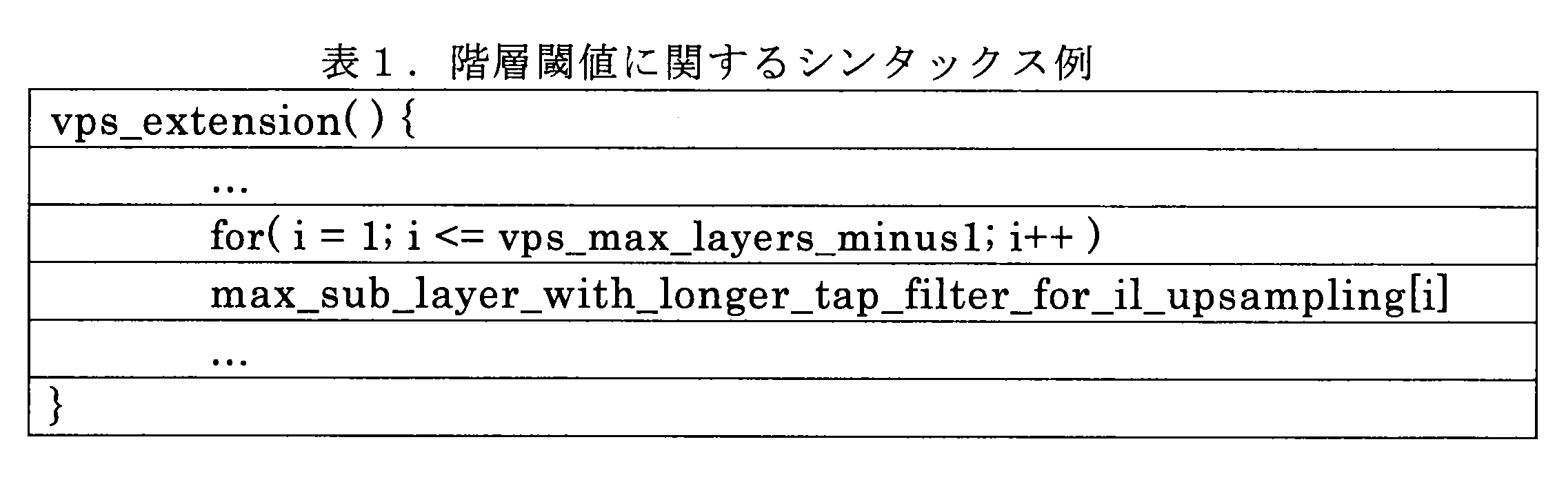
表1において、インデックスiで特定されるエンハンスメントレイヤごとに、パラメータmax_sub_layer_with_longer_tap_filter_for_il_upsampling[i]によって、時間階層と比較される階層閾値が定義される。当該パラメータは、可逆符号化部116により符号化される。エンハンスメントレイヤの符号化の際、フィルタ制御部146は、このように定義され得る階層閾値よりも浅い時間階層のピクチャについて、第1のフィルタタップ数(例えば、輝度成分について7又は8タップ)を選択する。また、フィルタ制御部146は、階層閾値よりも深い時間階層のピクチャについて、第1のフィルタタップ数よりも少ない第2のフィルタタップ数(例えば、輝度成分について4タップ)を選択する。
In Table 1, for each enhancement layer specified by index i, a layer threshold value to be compared with the time layer is defined by the parameter max_sub_layer_with_longer_tap_filter_for_il_upsampling [i]. The parameter is encoded by the lossless encoding unit 116. When encoding the enhancement layer, the filter control unit 146 selects the first filter tap number (for example, 7 or 8 taps for the luminance component) for the picture in the time layer shallower than the layer threshold that can be defined in this way. To do. In addition, the filter control unit 146 selects a second filter tap number (for example, 4 taps for the luminance component) that is smaller than the first filter tap number for the pictures in the temporal hierarchy deeper than the hierarchical threshold.
図22は、第2の実施形態の上述した変形例についてさらに説明するための説明図である。図22の下段にはベースレイヤに含まれるピクチャP00~P08が、上段にエンハンスメントレイヤに含まれるピクチャP10~P18がそれぞれ示されている。ピクチャP00は、Iピクチャであり、他のピクチャを参照することなく復号可能である。ピクチャP00の時間階層TL0は、最も浅い。次に浅い時間階層TL1に属するピクチャP04及びP08は、ピクチャP00のみを参照することにより復号可能である。次に浅い時間階層TL2に属するピクチャP02及びP06は、ピクチャP00、P04及びP08の1つ以上を参照することにより復号可能である。最も深い時間階層TL3に属するピクチャP01、P03、P05及びP07は、ピクチャP00、P02、P04、P06及びP08の1つ以上を参照することにより復号可能である。なお、図22の例に限定されず、最も浅い時間階層TL0は、Iピクチャ以外のピクチャタイプのピクチャを含んでもよい。エンハンスメントレイヤのピクチャP10~P18は、それぞれ、インターレイヤ予測においてベースレイヤのピクチャP00~P08のアップサンプリング画像を参照することにより復号可能である。このような時間階層において、例えば階層閾値Th0が2に等しい場合、時間階層TL0及びTL01に属するピクチャP00、P04及びP08のアップサンプリングの際には、より多くのフィルタタップ数が使用され得る。一方、時間階層TL2及びTL03に属する残りのピクチャのアップサンプリングの際には、より少ないフィルタタップ数が使用され得る。
FIG. 22 is an explanatory diagram for further explaining the above-described modification of the second embodiment. The lower part of FIG. 22 shows pictures P 00 to P 08 included in the base layer, and the upper part shows pictures P 10 to P 18 included in the enhancement layer. The picture P 00 is an I picture and can be decoded without referring to other pictures. Time hierarchy TL0 of the picture P 00 is the most shallow. Next, pictures P 04 and P 08 belonging to the next shallowest time layer TL 1 can be decoded by referring only to picture P 00 . Pictures P 02 and P 06 belonging to the next shallowest time layer TL 2 can be decoded by referring to one or more of the pictures P 00 , P 04 and P 08 . Pictures P 01 , P 03 , P 05 and P 07 belonging to the deepest time hierarchy TL 3 can be decoded by referring to one or more of the pictures P 00 , P 02 , P 04 , P 06 and P 08 . Note that the shallowest time hierarchy TL0 is not limited to the example of FIG. 22, and may include pictures of a picture type other than the I picture. The enhancement layer pictures P 10 to P 18 can be decoded by referring to the up-sampled images of the base layer pictures P 00 to P 08 in the inter-layer prediction, respectively. In such a time layer, for example, when the layer threshold value Th0 is equal to 2, a larger number of filter taps is used when up-sampling the pictures P 00 , P 04 and P 08 belonging to the time layers TL 0 and TL 01. obtain. On the other hand, when upsampling the remaining pictures belonging to the time layers TL2 and TL03, a smaller number of filter taps can be used.
あるピクチャのアップサンプリングに伴う画質の劣化は、当該ピクチャを参照する他のピクチャの予測精度に悪影響を与える。そこで、上述した変形例のように、より多くの他のピクチャから参照される時間階層の浅いピクチャについて、アップサンプリングフィルタのタップ数をより多くすることで、予測精度の向上によって符号化効率を高めることができる。逆に、他のピクチャから(全く又はあまり)参照されない時間階層の深いピクチャについては、アップサンプリングフィルタのタップ数を削減することで、符号化効率を犠牲にすることなく計算コストを削減することができる。
Degradation of image quality due to upsampling of a picture adversely affects the prediction accuracy of other pictures that refer to the picture. Therefore, as in the above-described modification, the coding efficiency is improved by improving the prediction accuracy by increasing the number of taps of the upsampling filter for a picture having a shallow temporal hierarchy that is referred to by more other pictures. be able to. On the other hand, for a picture with a deep temporal hierarchy that is not referenced (otherwise or not) by other pictures, reducing the number of taps of the upsampling filter can reduce the calculation cost without sacrificing the coding efficiency. it can.
[6-2.EL復号部の構成例]
図23は、第2の実施形態に係るEL復号部6bの構成の一例を示すブロック図である。図23を参照すると、EL復号部6bは、蓄積バッファ61、可逆復号部162、逆量子化部63、逆直交変換部64、加算部65、ループフィルタ66、並び替えバッファ67、D/A変換部68、フレームメモリ69、セレクタ70及び71、イントラ予測部80、インター予測部85並びにアップサンプリング部190を備える。 [6-2. Configuration example of EL decoding unit]
FIG. 23 is a block diagram illustrating an example of a configuration of theEL decoding unit 6b according to the second embodiment. Referring to FIG. 23, the EL decoding unit 6b includes an accumulation buffer 61, a lossless decoding unit 162, an inverse quantization unit 63, an inverse orthogonal transformation unit 64, an addition unit 65, a loop filter 66, a rearrangement buffer 67, and a D / A conversion. Unit 68, frame memory 69, selectors 70 and 71, intra prediction unit 80, inter prediction unit 85, and upsampling unit 190.
図23は、第2の実施形態に係るEL復号部6bの構成の一例を示すブロック図である。図23を参照すると、EL復号部6bは、蓄積バッファ61、可逆復号部162、逆量子化部63、逆直交変換部64、加算部65、ループフィルタ66、並び替えバッファ67、D/A変換部68、フレームメモリ69、セレクタ70及び71、イントラ予測部80、インター予測部85並びにアップサンプリング部190を備える。 [6-2. Configuration example of EL decoding unit]
FIG. 23 is a block diagram illustrating an example of a configuration of the
可逆復号部162は、蓄積バッファ61から入力されるエンハンスメントレイヤの符号化ストリームから、符号化の際に使用された符号化方式に従ってエンハンスメントレイヤの量子化データを復号する。また、可逆復号部162は、符号化ストリームのヘッダ領域に挿入されている情報を復号する。可逆復号部162により復号される情報は、例えば、イントラ予測に関する情報及びインター予測に関する情報を含み得る。本実施形態において、可逆復号部162は、アップサンプリングフィルタの最適なフィルタ構成を示すフィルタ構成情報を、符号化ストリームのVPS、SPS又はPPSから復号する。フィルタ構成情報は、上述したように、映像データ、シーケンス又はピクチャごとに、2つ以上のフィルタ構成の候補のうちの1つを示す情報であってよい。単純な例において、当該情報は、フィルタ構成の候補のいずれかを指し示すインデックスを含んでもよい。その代わりに、当該情報は、上述した変形例のように、ピクチャごとの時間階層と比較される階層閾値を含んでもよい。可逆復号部162は、量子化データを逆量子化部63へ出力する。また、可逆復号部162は、イントラ予測に関する情報をイントラ予測部80へ出力する。イントラ予測に関する情報は、量子化行列の切替えのために、逆量子化部63へ出力されてもよい。また、可逆復号部162は、インター予測に関する情報をインター予測部85へ出力する。また、可逆復号部162は、フィルタ構成情報をアップサンプリング部190へ出力する。
The lossless decoding unit 162 decodes enhancement layer quantized data from the enhancement layer encoded stream input from the accumulation buffer 61 according to the encoding method used for encoding. In addition, the lossless decoding unit 162 decodes information inserted in the header area of the encoded stream. The information decoded by the lossless decoding unit 162 may include information related to intra prediction and information related to inter prediction, for example. In the present embodiment, the lossless decoding unit 162 decodes the filter configuration information indicating the optimal filter configuration of the upsampling filter from the VPS, SPS, or PPS of the encoded stream. As described above, the filter configuration information may be information indicating one of two or more filter configuration candidates for each video data, sequence, or picture. In a simple example, the information may include an index that points to any of the filter configuration candidates. Instead, the information may include a hierarchy threshold that is compared with the temporal hierarchy for each picture, as in the above-described modification. The lossless decoding unit 162 outputs the quantized data to the inverse quantization unit 63. Further, the lossless decoding unit 162 outputs information related to intra prediction to the intra prediction unit 80. Information regarding intra prediction may be output to the inverse quantization unit 63 for switching the quantization matrix. Further, the lossless decoding unit 162 outputs information related to inter prediction to the inter prediction unit 85. In addition, the lossless decoding unit 162 outputs the filter configuration information to the upsampling unit 190.
アップサンプリング部190は、共通メモリ7によりバッファリングされるベースレイヤの画像を、ベースレイヤとエンハンスメントレイヤとの間の解像度比に従ってアップサンプリングする。アップサンプリング部190によりアップサンプリングされた画像は、フレームメモリ69に格納され、イントラ予測部80又はインター予測部85により、インターレイヤ予測において参照画像として使用され得る。アップサンプリング部190は、符号化ストリームから復号されるフィルタ構成情報に従って、アップサンプリングフィルタのフィルタ構成を選択する。
The upsampling unit 190 upsamples the base layer image buffered by the common memory 7 in accordance with the resolution ratio between the base layer and the enhancement layer. The image up-sampled by the up-sampling unit 190 is stored in the frame memory 69 and can be used as a reference image in the inter-layer prediction by the intra prediction unit 80 or the inter prediction unit 85. The upsampling unit 190 selects a filter configuration of the upsampling filter according to the filter configuration information decoded from the encoded stream.
図24は、図23に示したアップサンプリング部190の構成の一例を示すブロック図である。図24を参照すると、アップサンプリング部190は、シンタックスバッファ191、フィルタ制御部195、係数メモリ96及びアップサンプリングフィルタ97を有する。
FIG. 24 is a block diagram showing an example of the configuration of the upsampling unit 190 shown in FIG. Referring to FIG. 24, the upsampling unit 190 includes a syntax buffer 191, a filter control unit 195, a coefficient memory 96, and an upsampling filter 97.
シンタックスバッファ191は、フィルタ制御部195がアップサンプリングを制御する際に使用するパラメータを記憶するバッファである。例えば、シンタックスバッファ191は、ベースレイヤ画像とエンハンスメントレイヤ画像との間の解像度比を記憶する。解像度比は、可逆復号部62により、VPS、又はエンハンスメントレイヤのSPS若しくはPPSから復号され得る。また、シンタックスバッファ191は、可逆復号部162により復号され得るフィルタ構成情報を記憶する。
The syntax buffer 191 is a buffer that stores parameters used when the filter control unit 195 controls upsampling. For example, the syntax buffer 191 stores the resolution ratio between the base layer image and the enhancement layer image. The resolution ratio can be decoded from the VPS or the enhancement layer SPS or PPS by the lossless decoding unit 62. The syntax buffer 191 stores filter configuration information that can be decoded by the lossless decoding unit 162.
フィルタ制御部195は、ベースレイヤの画像のアップサンプリングのための複数のフィルタ構成の候補から、シンタックスバッファ191により記憶されるフィルタ構成情報に対応するフィルタ構成を、映像データ、シーケンス又はピクチャなどの処理単位ごとに選択する。アップサンプリングされる画像は、ベースレイヤの復号画像及び予測誤差画像の一方又は双方であってよい。アップサンプリングフィルタ97は、フィルタ制御部195により選択されるフィルタ構成に対応するアップサンプリング画像を、ベースレイヤ画像をアップサンプリングすることにより生成する。アップサンプリングフィルタ97により生成されるアップサンプリング画像は、フレームメモリ69に格納される。
The filter control unit 195 selects a filter configuration corresponding to the filter configuration information stored by the syntax buffer 191 from a plurality of filter configuration candidates for upsampling the base layer image, such as video data, a sequence, or a picture. Select for each processing unit. The upsampled image may be one or both of a base layer decoded image and a prediction error image. The upsampling filter 97 generates an upsampling image corresponding to the filter configuration selected by the filter control unit 195 by upsampling the base layer image. The upsampled image generated by the upsampling filter 97 is stored in the frame memory 69.
フィルタ構成情報がフィルタ構成の候補のうちの1つをインデックスによって指し示す典型的な例において、フィルタ制御部195は、当該インデックスに従って、映像データ、シーケンス又はピクチャなどの処理単位ごとにフィルタ構成を選択する。
In a typical example in which the filter configuration information indicates one of the filter configuration candidates by an index, the filter control unit 195 selects a filter configuration for each processing unit such as video data, a sequence, or a picture according to the index. .
また、フィルタ構成情報がピクチャごとの時間階層と比較される階層閾値を含む変形例において、フィルタ制御部195は、復号された階層閾値(例えば、表1に例示したmax_sub_layer_with_longer_tap_filter_for_il_upsampling[i])よりも浅い時間階層のピクチャについて第1のフィルタタップ数を選択し、当該階層閾値よりも深い時間階層のピクチャについて第1のフィルタタップ数よりも少ない第2のフィルタタップ数を選択する。
Further, in the modification in which the filter configuration information includes a layer threshold value that is compared with the time layer for each picture, the filter control unit 195 is shallower than the decoded layer threshold value (for example, max_sub_layer_with_longer_tap_filter_for_il_upsampling [i] illustrated in Table 1). A first number of filter taps is selected for a picture in the time hierarchy, and a second number of filter taps smaller than the first number of filter taps is selected for a picture in the time hierarchy deeper than the hierarchy threshold.
[6-3.符号化時のアップサンプリング処理の流れ]
図25は、エンハンスメントレイヤの符号化処理におけるアップサンプリング処理の流れの一例を示すフローチャートである。 [6-3. Flow of upsampling process during encoding]
FIG. 25 is a flowchart illustrating an example of the upsampling process flow in the enhancement layer encoding process.
図25は、エンハンスメントレイヤの符号化処理におけるアップサンプリング処理の流れの一例を示すフローチャートである。 [6-3. Flow of upsampling process during encoding]
FIG. 25 is a flowchart illustrating an example of the upsampling process flow in the enhancement layer encoding process.
図25を参照すると、まず、フィルタ制御部146は、設定部145による設定に従って、ピクチャ(又はシーケンスなど)の処理単位ごとに、アップサンプリングフィルタ48の最適なフィルタ構成を選択する(ステップS120)。次に、フィルタ制御部146は、エンハンスメントレイヤの注目ブロックに対応するベースレイヤの参照ブロックを識別する(ステップS122)。ここで識別される参照ブロックは、注目ブロックのコロケーテッドブロックであってよい。
Referring to FIG. 25, first, the filter control unit 146 selects an optimal filter configuration of the upsampling filter 48 for each processing unit of a picture (or a sequence) according to the setting by the setting unit 145 (step S120). Next, the filter control unit 146 identifies the reference block of the base layer corresponding to the target block of the enhancement layer (step S122). The reference block identified here may be a collocated block of the block of interest.
ステップS126及びステップS128の処理は、注目ブロック内の補間画素位置ごとに繰り返される(ステップS124)。補間画素位置は、レイヤ間の解像度比に応じて決定される。各繰り返しにおいて、アップサンプリングフィルタ48は、フィルタ制御部146により選択されたフィルタ構成で、ベースレイヤの画像をフィルタリングすることにより、補間画素値を算出する(ステップS126)。次に、アップサンプリングフィルタ48は、アップサンプリング後の補間画素値をフレームメモリ25に格納する(ステップS128)。
The processing of step S126 and step S128 is repeated for each interpolation pixel position in the block of interest (step S124). The interpolation pixel position is determined according to the resolution ratio between layers. In each iteration, the upsampling filter 48 calculates an interpolated pixel value by filtering the base layer image with the filter configuration selected by the filter control unit 146 (step S126). Next, the upsampling filter 48 stores the interpolated pixel value after the upsampling in the frame memory 25 (step S128).
注目ブロック内の全ての補間画素位置についてループが終了すると、フィルタ制御部146は、次の注目ブロックが存在するかを判定する(ステップS130)。次の注目ブロックが存在する場合には、処理はステップS120へ戻り、次の注目ブロックについて上述した処理が繰り返される。次の注目ブロックが存在しない場合、フィルタ制御部146により生成される注目ブロックについてのフィルタ構成情報が、可逆符号化部116により符号化され得る(ステップS138)。そして、図25のアップサンプリング処理は終了する。
When the loop is completed for all the interpolation pixel positions in the target block, the filter control unit 146 determines whether there is a next target block (step S130). If there is a next block of interest, the process returns to step S120, and the above-described processing is repeated for the next block of interest. When the next block of interest does not exist, the filter configuration information about the block of interest generated by the filter control unit 146 can be encoded by the lossless encoding unit 116 (step S138). Then, the upsampling process in FIG. 25 ends.
[6-4.復号時のアップサンプリング処理の流れ]
図26は、エンハンスメントレイヤの復号処理におけるアップサンプリング処理の流れの一例を示すフローチャートである。 [6-4. Flow of upsampling process during decoding]
FIG. 26 is a flowchart illustrating an example of the upsampling process flow in the enhancement layer decoding process.
図26は、エンハンスメントレイヤの復号処理におけるアップサンプリング処理の流れの一例を示すフローチャートである。 [6-4. Flow of upsampling process during decoding]
FIG. 26 is a flowchart illustrating an example of the upsampling process flow in the enhancement layer decoding process.
図26を参照すると、まず、フィルタ制御部195は、VPS、SPS又はPPSから復号されるフィルタ構成情報を、シンタックスバッファ191から取得する(ステップS180)。
Referring to FIG. 26, first, the filter control unit 195 acquires filter configuration information decoded from VPS, SPS, or PPS from the syntax buffer 191 (step S180).
次に、フィルタ制御部195は、エンハンスメントレイヤの注目ブロックに対応するベースレイヤの参照ブロックを識別する(ステップS182)。ここで識別される参照ブロックは、注目ブロックのコロケーテッドブロックであってよい。
Next, the filter control unit 195 identifies the reference block of the base layer corresponding to the target block of the enhancement layer (step S182). The reference block identified here may be a collocated block of the block of interest.
ステップS186及びステップS188の処理は、注目ブロック内の補間画素位置ごとに繰り返される(ステップS184)。補間画素位置は、レイヤ間の解像度比に応じて決定される。各繰り返しにおいて、アップサンプリングフィルタ97は、フィルタ構成情報により示されるフィルタ構成で、ベースレイヤの画像をフィルタリングすることにより、補間画素値を算出する(ステップS186)。次に、アップサンプリングフィルタ97は、算出したアップサンプリング後の補間画素値をフレームメモリ69に格納する(ステップS188)。
The processing of step S186 and step S188 is repeated for each interpolation pixel position in the block of interest (step S184). The interpolation pixel position is determined according to the resolution ratio between layers. In each iteration, the upsampling filter 97 calculates an interpolated pixel value by filtering the base layer image with the filter configuration indicated by the filter configuration information (step S186). Next, the upsampling filter 97 stores the calculated interpolated pixel value after upsampling in the frame memory 69 (step S188).
注目ブロック内の全ての補間画素位置についてループが終了した後、次の注目ブロックが存在する場合には、処理はステップS182へ戻り、次の注目ブロックについて上述した処理が繰り返される(ステップS190)。次の注目ブロックが存在しない場合には、図26のアップサンプリング処理は終了する。
When the next block of interest exists after the loop has been completed for all the interpolated pixel positions in the block of interest, the process returns to step S182, and the above-described processing is repeated for the next block of interest (step S190). If there is no next block of interest, the upsampling process in FIG. 26 ends.
<7.応用例>
[7-1.様々な製品への応用]
上述した様々な実施形態に係る画像符号化装置10及び画像復号装置60は、衛星放送、ケーブルTVなどの有線放送、インターネット上での配信、及びセルラー通信による端末への配信などにおける送信機若しくは受信機、光ディスク、磁気ディスク及びフラッシュメモリなどの媒体に画像を記録する記録装置、又は、これら記憶媒体から画像を再生する再生装置などの様々な電子機器に応用され得る。以下、4つの応用例について説明する。 <7. Application example>
[7-1. Application to various products]
Theimage encoding device 10 and the image decoding device 60 according to the various embodiments described above are a transmitter or a receiver in satellite broadcasting, cable broadcasting such as cable TV, distribution on the Internet, and distribution to terminals by cellular communication. The present invention can be applied to various electronic devices such as a recording device that records an image on a medium such as a computer, an optical disk, a magnetic disk, and a flash memory, or a reproducing device that reproduces an image from these storage media. Hereinafter, four application examples will be described.
[7-1.様々な製品への応用]
上述した様々な実施形態に係る画像符号化装置10及び画像復号装置60は、衛星放送、ケーブルTVなどの有線放送、インターネット上での配信、及びセルラー通信による端末への配信などにおける送信機若しくは受信機、光ディスク、磁気ディスク及びフラッシュメモリなどの媒体に画像を記録する記録装置、又は、これら記憶媒体から画像を再生する再生装置などの様々な電子機器に応用され得る。以下、4つの応用例について説明する。 <7. Application example>
[7-1. Application to various products]
The
(1)第1の応用例
図27は、テレビジョン装置の概略的な構成の一例を示している。テレビジョン装置900は、アンテナ901、チューナ902、デマルチプレクサ903、デコーダ904、映像信号処理部905、表示部906、音声信号処理部907、スピーカ908、外部インタフェース909、制御部910、ユーザインタフェース911、及びバス912を備える。 (1) First Application Example FIG. 27 illustrates an example of a schematic configuration of a television device. Thetelevision apparatus 900 includes an antenna 901, a tuner 902, a demultiplexer 903, a decoder 904, a video signal processing unit 905, a display unit 906, an audio signal processing unit 907, a speaker 908, an external interface 909, a control unit 910, a user interface 911, And a bus 912.
図27は、テレビジョン装置の概略的な構成の一例を示している。テレビジョン装置900は、アンテナ901、チューナ902、デマルチプレクサ903、デコーダ904、映像信号処理部905、表示部906、音声信号処理部907、スピーカ908、外部インタフェース909、制御部910、ユーザインタフェース911、及びバス912を備える。 (1) First Application Example FIG. 27 illustrates an example of a schematic configuration of a television device. The
チューナ902は、アンテナ901を介して受信される放送信号から所望のチャンネルの信号を抽出し、抽出した信号を復調する。そして、チューナ902は、復調により得られた符号化ビットストリームをデマルチプレクサ903へ出力する。即ち、チューナ902は、画像が符号化されている符号化ストリームを受信する、テレビジョン装置900における伝送手段としての役割を有する。
Tuner 902 extracts a signal of a desired channel from a broadcast signal received via antenna 901, and demodulates the extracted signal. Then, the tuner 902 outputs the encoded bit stream obtained by the demodulation to the demultiplexer 903. In other words, the tuner 902 serves as a transmission unit in the television apparatus 900 that receives an encoded stream in which an image is encoded.
デマルチプレクサ903は、符号化ビットストリームから視聴対象の番組の映像ストリーム及び音声ストリームを分離し、分離した各ストリームをデコーダ904へ出力する。また、デマルチプレクサ903は、符号化ビットストリームからEPG(Electronic Program Guide)などの補助的なデータを抽出し、抽出したデータを制御部910に供給する。なお、デマルチプレクサ903は、符号化ビットストリームがスクランブルされている場合には、デスクランブルを行ってもよい。
The demultiplexer 903 separates the video stream and audio stream of the viewing target program from the encoded bit stream, and outputs each separated stream to the decoder 904. In addition, the demultiplexer 903 extracts auxiliary data such as EPG (Electronic Program Guide) from the encoded bit stream, and supplies the extracted data to the control unit 910. Note that the demultiplexer 903 may perform descrambling when the encoded bit stream is scrambled.
デコーダ904は、デマルチプレクサ903から入力される映像ストリーム及び音声ストリームを復号する。そして、デコーダ904は、復号処理により生成される映像データを映像信号処理部905へ出力する。また、デコーダ904は、復号処理により生成される音声データを音声信号処理部907へ出力する。
The decoder 904 decodes the video stream and audio stream input from the demultiplexer 903. Then, the decoder 904 outputs the video data generated by the decoding process to the video signal processing unit 905. In addition, the decoder 904 outputs audio data generated by the decoding process to the audio signal processing unit 907.
映像信号処理部905は、デコーダ904から入力される映像データを再生し、表示部906に映像を表示させる。また、映像信号処理部905は、ネットワークを介して供給されるアプリケーション画面を表示部906に表示させてもよい。また、映像信号処理部905は、映像データについて、設定に応じて、例えばノイズ除去などの追加的な処理を行ってもよい。さらに、映像信号処理部905は、例えばメニュー、ボタン又はカーソルなどのGUI(Graphical User Interface)の画像を生成し、生成した画像を出力画像に重畳してもよい。
The video signal processing unit 905 reproduces the video data input from the decoder 904 and causes the display unit 906 to display the video. In addition, the video signal processing unit 905 may cause the display unit 906 to display an application screen supplied via a network. Further, the video signal processing unit 905 may perform additional processing such as noise removal on the video data according to the setting. Further, the video signal processing unit 905 may generate a GUI (Graphical User Interface) image such as a menu, a button, or a cursor, and superimpose the generated image on the output image.
表示部906は、映像信号処理部905から供給される駆動信号により駆動され、表示デバイス(例えば、液晶ディスプレイ、プラズマディスプレイ又はOLEDなど)の映像面上に映像又は画像を表示する。
The display unit 906 is driven by a drive signal supplied from the video signal processing unit 905, and displays a video or an image on a video screen of a display device (for example, a liquid crystal display, a plasma display, or an OLED).
音声信号処理部907は、デコーダ904から入力される音声データについてD/A変換及び増幅などの再生処理を行い、スピーカ908から音声を出力させる。また、音声信号処理部907は、音声データについてノイズ除去などの追加的な処理を行ってもよい。
The audio signal processing unit 907 performs reproduction processing such as D / A conversion and amplification on the audio data input from the decoder 904, and outputs audio from the speaker 908. The audio signal processing unit 907 may perform additional processing such as noise removal on the audio data.
外部インタフェース909は、テレビジョン装置900と外部機器又はネットワークとを接続するためのインタフェースである。例えば、外部インタフェース909を介して受信される映像ストリーム又は音声ストリームが、デコーダ904により復号されてもよい。即ち、外部インタフェース909もまた、画像が符号化されている符号化ストリームを受信する、テレビジョン装置900における伝送手段としての役割を有する。
The external interface 909 is an interface for connecting the television apparatus 900 to an external device or a network. For example, a video stream or an audio stream received via the external interface 909 may be decoded by the decoder 904. That is, the external interface 909 also has a role as a transmission unit in the television apparatus 900 that receives an encoded stream in which an image is encoded.
制御部910は、CPU(Central Processing Unit)などのプロセッサ、並びにRAM(Random Access Memory)及びROM(Read Only Memory)などのメモリを有する。メモリは、CPUにより実行されるプログラム、プログラムデータ、EPGデータ、及びネットワークを介して取得されるデータなどを記憶する。メモリにより記憶されるプログラムは、例えば、テレビジョン装置900の起動時にCPUにより読み込まれ、実行される。CPUは、プログラムを実行することにより、例えばユーザインタフェース911から入力される操作信号に応じて、テレビジョン装置900の動作を制御する。
The control unit 910 has a processor such as a CPU (Central Processing Unit) and a memory such as a RAM (Random Access Memory) and a ROM (Read Only Memory). The memory stores a program executed by the CPU, program data, EPG data, data acquired via a network, and the like. The program stored in the memory is read and executed by the CPU when the television device 900 is activated, for example. The CPU controls the operation of the television device 900 according to an operation signal input from the user interface 911, for example, by executing the program.
ユーザインタフェース911は、制御部910と接続される。ユーザインタフェース911は、例えば、ユーザがテレビジョン装置900を操作するためのボタン及びスイッチ、並びに遠隔制御信号の受信部などを有する。ユーザインタフェース911は、これら構成要素を介してユーザによる操作を検出して操作信号を生成し、生成した操作信号を制御部910へ出力する。
The user interface 911 is connected to the control unit 910. The user interface 911 includes, for example, buttons and switches for the user to operate the television device 900, a remote control signal receiving unit, and the like. The user interface 911 detects an operation by the user via these components, generates an operation signal, and outputs the generated operation signal to the control unit 910.
バス912は、チューナ902、デマルチプレクサ903、デコーダ904、映像信号処理部905、音声信号処理部907、外部インタフェース909及び制御部910を相互に接続する。
The bus 912 connects the tuner 902, the demultiplexer 903, the decoder 904, the video signal processing unit 905, the audio signal processing unit 907, the external interface 909, and the control unit 910 to each other.
このように構成されたテレビジョン装置900において、デコーダ904は、画像復号装置60の機能を有する。それにより、テレビジョン装置900が空間解像度の異なるレイヤの画像を復号する際に、画質の劣化を回避しつつアップサンプリングの計算コストを抑制することができる。
In the thus configured television device 900, the decoder 904 has the function of the image decoding device 60. Thereby, when the television apparatus 900 decodes images of layers having different spatial resolutions, it is possible to suppress the calculation cost of upsampling while avoiding deterioration in image quality.
(7)第2の応用例
図28は、携帯電話機の概略的な構成の一例を示している。携帯電話機920は、アンテナ921、通信部922、音声コーデック923、スピーカ924、マイクロホン925、カメラ部926、画像処理部927、多重分離部928、記録再生部929、表示部930、制御部931、操作部932、及びバス933を備える。 (7) Second Application Example FIG. 28 shows an example of a schematic configuration of a mobile phone. Acellular phone 920 includes an antenna 921, a communication unit 922, an audio codec 923, a speaker 924, a microphone 925, a camera unit 926, an image processing unit 927, a demultiplexing unit 928, a recording / reproducing unit 929, a display unit 930, a control unit 931, an operation A portion 932 and a bus 933.
図28は、携帯電話機の概略的な構成の一例を示している。携帯電話機920は、アンテナ921、通信部922、音声コーデック923、スピーカ924、マイクロホン925、カメラ部926、画像処理部927、多重分離部928、記録再生部929、表示部930、制御部931、操作部932、及びバス933を備える。 (7) Second Application Example FIG. 28 shows an example of a schematic configuration of a mobile phone. A
アンテナ921は、通信部922に接続される。スピーカ924及びマイクロホン925は、音声コーデック923に接続される。操作部932は、制御部931に接続される。バス933は、通信部922、音声コーデック923、カメラ部926、画像処理部927、多重分離部928、記録再生部929、表示部930、及び制御部931を相互に接続する。
The antenna 921 is connected to the communication unit 922. The speaker 924 and the microphone 925 are connected to the audio codec 923. The operation unit 932 is connected to the control unit 931. The bus 933 connects the communication unit 922, the audio codec 923, the camera unit 926, the image processing unit 927, the demultiplexing unit 928, the recording / reproducing unit 929, the display unit 930, and the control unit 931 to each other.
携帯電話機920は、音声通話モード、データ通信モード、撮影モード及びテレビ電話モードを含む様々な動作モードで、音声信号の送受信、電子メール又は画像データの送受信、画像の撮像、及びデータの記録などの動作を行う。
The mobile phone 920 has various operation modes including a voice call mode, a data communication mode, a shooting mode, and a videophone mode, and is used for sending and receiving voice signals, sending and receiving e-mail or image data, taking images, and recording data. Perform the action.
音声通話モードにおいて、マイクロホン925により生成されるアナログ音声信号は、音声コーデック923に供給される。音声コーデック923は、アナログ音声信号を音声データへ変換し、変換された音声データをA/D変換し圧縮する。そして、音声コーデック923は、圧縮後の音声データを通信部922へ出力する。通信部922は、音声データを符号化及び変調し、送信信号を生成する。そして、通信部922は、生成した送信信号をアンテナ921を介して基地局(図示せず)へ送信する。また、通信部922は、アンテナ921を介して受信される無線信号を増幅し及び周波数変換し、受信信号を取得する。そして、通信部922は、受信信号を復調及び復号して音声データを生成し、生成した音声データを音声コーデック923へ出力する。音声コーデック923は、音声データを伸張し及びD/A変換し、アナログ音声信号を生成する。そして、音声コーデック923は、生成した音声信号をスピーカ924に供給して音声を出力させる。
In the voice call mode, the analog voice signal generated by the microphone 925 is supplied to the voice codec 923. The audio codec 923 converts an analog audio signal into audio data, A / D converts the compressed audio data, and compresses it. Then, the audio codec 923 outputs the compressed audio data to the communication unit 922. The communication unit 922 encodes and modulates the audio data and generates a transmission signal. Then, the communication unit 922 transmits the generated transmission signal to a base station (not shown) via the antenna 921. In addition, the communication unit 922 amplifies a radio signal received via the antenna 921 and performs frequency conversion to acquire a received signal. Then, the communication unit 922 demodulates and decodes the received signal to generate audio data, and outputs the generated audio data to the audio codec 923. The audio codec 923 expands the audio data and performs D / A conversion to generate an analog audio signal. Then, the audio codec 923 supplies the generated audio signal to the speaker 924 to output audio.
また、データ通信モードにおいて、例えば、制御部931は、操作部932を介するユーザによる操作に応じて、電子メールを構成する文字データを生成する。また、制御部931は、文字を表示部930に表示させる。また、制御部931は、操作部932を介するユーザからの送信指示に応じて電子メールデータを生成し、生成した電子メールデータを通信部922へ出力する。通信部922は、電子メールデータを符号化及び変調し、送信信号を生成する。そして、通信部922は、生成した送信信号をアンテナ921を介して基地局(図示せず)へ送信する。また、通信部922は、アンテナ921を介して受信される無線信号を増幅し及び周波数変換し、受信信号を取得する。そして、通信部922は、受信信号を復調及び復号して電子メールデータを復元し、復元した電子メールデータを制御部931へ出力する。制御部931は、表示部930に電子メールの内容を表示させると共に、電子メールデータを記録再生部929の記憶媒体に記憶させる。
Further, in the data communication mode, for example, the control unit 931 generates character data constituting the e-mail in response to an operation by the user via the operation unit 932. In addition, the control unit 931 causes the display unit 930 to display characters. In addition, the control unit 931 generates e-mail data in response to a transmission instruction from the user via the operation unit 932, and outputs the generated e-mail data to the communication unit 922. The communication unit 922 encodes and modulates email data and generates a transmission signal. Then, the communication unit 922 transmits the generated transmission signal to a base station (not shown) via the antenna 921. In addition, the communication unit 922 amplifies a radio signal received via the antenna 921 and performs frequency conversion to acquire a received signal. Then, the communication unit 922 demodulates and decodes the received signal to restore the email data, and outputs the restored email data to the control unit 931. The control unit 931 displays the content of the electronic mail on the display unit 930 and stores the electronic mail data in the storage medium of the recording / reproducing unit 929.
記録再生部929は、読み書き可能な任意の記憶媒体を有する。例えば、記憶媒体は、RAM又はフラッシュメモリなどの内蔵型の記憶媒体であってもよく、ハードディスク、磁気ディスク、光磁気ディスク、光ディスク、USBメモリ、又はメモリカードなどの外部装着型の記憶媒体であってもよい。
The recording / reproducing unit 929 has an arbitrary readable / writable storage medium. For example, the storage medium may be a built-in storage medium such as a RAM or a flash memory, or an externally mounted storage medium such as a hard disk, a magnetic disk, a magneto-optical disk, an optical disk, a USB memory, or a memory card. May be.
また、撮影モードにおいて、例えば、カメラ部926は、被写体を撮像して画像データを生成し、生成した画像データを画像処理部927へ出力する。画像処理部927は、カメラ部926から入力される画像データを符号化し、符号化ストリームを記録再生部929の記憶媒体に記憶させる。
In the shooting mode, for example, the camera unit 926 images a subject to generate image data, and outputs the generated image data to the image processing unit 927. The image processing unit 927 encodes the image data input from the camera unit 926 and stores the encoded stream in the storage medium of the recording / playback unit 929.
また、テレビ電話モードにおいて、例えば、多重分離部928は、画像処理部927により符号化された映像ストリームと、音声コーデック923から入力される音声ストリームとを多重化し、多重化したストリームを通信部922へ出力する。通信部922は、ストリームを符号化及び変調し、送信信号を生成する。そして、通信部922は、生成した送信信号をアンテナ921を介して基地局(図示せず)へ送信する。また、通信部922は、アンテナ921を介して受信される無線信号を増幅し及び周波数変換し、受信信号を取得する。これら送信信号及び受信信号には、符号化ビットストリームが含まれ得る。そして、通信部922は、受信信号を復調及び復号してストリームを復元し、復元したストリームを多重分離部928へ出力する。多重分離部928は、入力されるストリームから映像ストリーム及び音声ストリームを分離し、映像ストリームを画像処理部927、音声ストリームを音声コーデック923へ出力する。画像処理部927は、映像ストリームを復号し、映像データを生成する。映像データは、表示部930に供給され、表示部930により一連の画像が表示される。音声コーデック923は、音声ストリームを伸張し及びD/A変換し、アナログ音声信号を生成する。そして、音声コーデック923は、生成した音声信号をスピーカ924に供給して音声を出力させる。
Further, in the videophone mode, for example, the demultiplexing unit 928 multiplexes the video stream encoded by the image processing unit 927 and the audio stream input from the audio codec 923, and the multiplexed stream is the communication unit 922. Output to. The communication unit 922 encodes and modulates the stream and generates a transmission signal. Then, the communication unit 922 transmits the generated transmission signal to a base station (not shown) via the antenna 921. In addition, the communication unit 922 amplifies a radio signal received via the antenna 921 and performs frequency conversion to acquire a received signal. These transmission signal and reception signal may include an encoded bit stream. Then, the communication unit 922 demodulates and decodes the received signal to restore the stream, and outputs the restored stream to the demultiplexing unit 928. The demultiplexing unit 928 separates the video stream and the audio stream from the input stream, and outputs the video stream to the image processing unit 927 and the audio stream to the audio codec 923. The image processing unit 927 decodes the video stream and generates video data. The video data is supplied to the display unit 930, and a series of images is displayed on the display unit 930. The audio codec 923 decompresses the audio stream and performs D / A conversion to generate an analog audio signal. Then, the audio codec 923 supplies the generated audio signal to the speaker 924 to output audio.
このように構成された携帯電話機920において、画像処理部927は、画像符号化装置10及び画像復号装置60の機能を有する。それにより、携帯電話機920が空間解像度の異なるレイヤの画像を符号化し又は復号する際に、画質の劣化を回避しつつアップサンプリングの計算コストを抑制することができる。
In the mobile phone 920 configured as described above, the image processing unit 927 has the functions of the image encoding device 10 and the image decoding device 60. Thereby, when the cellular phone 920 encodes or decodes images of layers having different spatial resolutions, it is possible to suppress the calculation cost of upsampling while avoiding deterioration in image quality.
(7)第3の応用例
図29は、記録再生装置の概略的な構成の一例を示している。記録再生装置940は、例えば、受信した放送番組の音声データ及び映像データを符号化して記録媒体に記録する。また、記録再生装置940は、例えば、他の装置から取得される音声データ及び映像データを符号化して記録媒体に記録してもよい。また、記録再生装置940は、例えば、ユーザの指示に応じて、記録媒体に記録されているデータをモニタ及びスピーカ上で再生する。このとき、記録再生装置940は、音声データ及び映像データを復号する。 (7) Third Application Example FIG. 29 shows an example of a schematic configuration of a recording / reproducing apparatus. For example, the recording / reproducingdevice 940 encodes audio data and video data of a received broadcast program and records the encoded data on a recording medium. In addition, the recording / reproducing device 940 may encode audio data and video data acquired from another device and record them on a recording medium, for example. In addition, the recording / reproducing device 940 reproduces data recorded on the recording medium on a monitor and a speaker, for example, in accordance with a user instruction. At this time, the recording / reproducing device 940 decodes the audio data and the video data.
図29は、記録再生装置の概略的な構成の一例を示している。記録再生装置940は、例えば、受信した放送番組の音声データ及び映像データを符号化して記録媒体に記録する。また、記録再生装置940は、例えば、他の装置から取得される音声データ及び映像データを符号化して記録媒体に記録してもよい。また、記録再生装置940は、例えば、ユーザの指示に応じて、記録媒体に記録されているデータをモニタ及びスピーカ上で再生する。このとき、記録再生装置940は、音声データ及び映像データを復号する。 (7) Third Application Example FIG. 29 shows an example of a schematic configuration of a recording / reproducing apparatus. For example, the recording / reproducing
記録再生装置940は、チューナ941、外部インタフェース942、エンコーダ943、HDD(Hard Disk Drive)944、ディスクドライブ945、セレクタ946、デコーダ947、OSD(On-Screen Display)948、制御部949、及びユーザインタフェース950を備える。
The recording / reproducing apparatus 940 includes a tuner 941, an external interface 942, an encoder 943, an HDD (Hard Disk Drive) 944, a disk drive 945, a selector 946, a decoder 947, an OSD (On-Screen Display) 948, a control unit 949, and a user interface. 950.
チューナ941は、アンテナ(図示せず)を介して受信される放送信号から所望のチャンネルの信号を抽出し、抽出した信号を復調する。そして、チューナ941は、復調により得られた符号化ビットストリームをセレクタ946へ出力する。即ち、チューナ941は、記録再生装置940における伝送手段としての役割を有する。
Tuner 941 extracts a signal of a desired channel from a broadcast signal received via an antenna (not shown), and demodulates the extracted signal. Then, the tuner 941 outputs the encoded bit stream obtained by the demodulation to the selector 946. That is, the tuner 941 has a role as a transmission unit in the recording / reproducing apparatus 940.
外部インタフェース942は、記録再生装置940と外部機器又はネットワークとを接続するためのインタフェースである。外部インタフェース942は、例えば、IEEE1394インタフェース、ネットワークインタフェース、USBインタフェース、又はフラッシュメモリインタフェースなどであってよい。例えば、外部インタフェース942を介して受信される映像データ及び音声データは、エンコーダ943へ入力される。即ち、外部インタフェース942は、記録再生装置940における伝送手段としての役割を有する。
The external interface 942 is an interface for connecting the recording / reproducing apparatus 940 to an external device or a network. The external interface 942 may be, for example, an IEEE 1394 interface, a network interface, a USB interface, or a flash memory interface. For example, video data and audio data received via the external interface 942 are input to the encoder 943. That is, the external interface 942 serves as a transmission unit in the recording / reproducing device 940.
エンコーダ943は、外部インタフェース942から入力される映像データ及び音声データが符号化されていない場合に、映像データ及び音声データを符号化する。そして、エンコーダ943は、符号化ビットストリームをセレクタ946へ出力する。
The encoder 943 encodes video data and audio data when the video data and audio data input from the external interface 942 are not encoded. Then, the encoder 943 outputs the encoded bit stream to the selector 946.
HDD944は、映像及び音声などのコンテンツデータが圧縮された符号化ビットストリーム、各種プログラム及びその他のデータを内部のハードディスクに記録する。また、HDD944は、映像及び音声の再生時に、これらデータをハードディスクから読み出す。
The HDD 944 records an encoded bit stream in which content data such as video and audio is compressed, various programs, and other data on an internal hard disk. Also, the HDD 944 reads out these data from the hard disk when playing back video and audio.
ディスクドライブ945は、装着されている記録媒体へのデータの記録及び読み出しを行う。ディスクドライブ945に装着される記録媒体は、例えばDVDディスク(DVD-Video、DVD-RAM、DVD-R、DVD-RW、DVD+R、DVD+RW等)又はBlu-ray(登録商標)ディスクなどであってよい。
The disk drive 945 performs recording and reading of data to and from the mounted recording medium. The recording medium loaded in the disk drive 945 may be, for example, a DVD disk (DVD-Video, DVD-RAM, DVD-R, DVD-RW, DVD + R, DVD + RW, etc.) or a Blu-ray (registered trademark) disk. .
セレクタ946は、映像及び音声の記録時には、チューナ941又はエンコーダ943から入力される符号化ビットストリームを選択し、選択した符号化ビットストリームをHDD944又はディスクドライブ945へ出力する。また、セレクタ946は、映像及び音声の再生時には、HDD944又はディスクドライブ945から入力される符号化ビットストリームをデコーダ947へ出力する。
The selector 946 selects an encoded bit stream input from the tuner 941 or the encoder 943 when recording video and audio, and outputs the selected encoded bit stream to the HDD 944 or the disk drive 945. In addition, the selector 946 outputs the encoded bit stream input from the HDD 944 or the disk drive 945 to the decoder 947 during video and audio reproduction.
デコーダ947は、符号化ビットストリームを復号し、映像データ及び音声データを生成する。そして、デコーダ947は、生成した映像データをOSD948へ出力する。また、デコーダ904は、生成した音声データを外部のスピーカへ出力する。
The decoder 947 decodes the encoded bit stream and generates video data and audio data. Then, the decoder 947 outputs the generated video data to the OSD 948. The decoder 904 outputs the generated audio data to an external speaker.
OSD948は、デコーダ947から入力される映像データを再生し、映像を表示する。また、OSD948は、表示する映像に、例えばメニュー、ボタン又はカーソルなどのGUIの画像を重畳してもよい。
The OSD 948 reproduces the video data input from the decoder 947 and displays the video. Further, the OSD 948 may superimpose a GUI image such as a menu, a button, or a cursor on the video to be displayed.
制御部949は、CPUなどのプロセッサ、並びにRAM及びROMなどのメモリを有する。メモリは、CPUにより実行されるプログラム、及びプログラムデータなどを記憶する。メモリにより記憶されるプログラムは、例えば、記録再生装置940の起動時にCPUにより読み込まれ、実行される。CPUは、プログラムを実行することにより、例えばユーザインタフェース950から入力される操作信号に応じて、記録再生装置940の動作を制御する。
The control unit 949 includes a processor such as a CPU and memories such as a RAM and a ROM. The memory stores a program executed by the CPU, program data, and the like. The program stored in the memory is read and executed by the CPU when the recording / reproducing apparatus 940 is activated, for example. The CPU controls the operation of the recording / reproducing device 940 according to an operation signal input from the user interface 950, for example, by executing the program.
ユーザインタフェース950は、制御部949と接続される。ユーザインタフェース950は、例えば、ユーザが記録再生装置940を操作するためのボタン及びスイッチ、並びに遠隔制御信号の受信部などを有する。ユーザインタフェース950は、これら構成要素を介してユーザによる操作を検出して操作信号を生成し、生成した操作信号を制御部949へ出力する。
The user interface 950 is connected to the control unit 949. The user interface 950 includes, for example, buttons and switches for the user to operate the recording / reproducing device 940, a remote control signal receiving unit, and the like. The user interface 950 detects an operation by the user via these components, generates an operation signal, and outputs the generated operation signal to the control unit 949.
このように構成された記録再生装置940において、エンコーダ943は、画像符号化装置10の機能を有する。また、デコーダ947は、画像復号装置60の機能を有する。それにより、記録再生装置940が空間解像度の異なるレイヤの画像を符号化し又は復号する際に、画質の劣化を回避しつつアップサンプリングの計算コストを抑制することができる。
In the thus configured recording / reproducing device 940, the encoder 943 has the function of the image encoding device 10. The decoder 947 has the function of the image decoding device 60. Thereby, when the recording / reproducing apparatus 940 encodes or decodes images of layers having different spatial resolutions, it is possible to suppress the calculation cost of upsampling while avoiding deterioration in image quality.
(7)第4の応用例
図30は、撮像装置の概略的な構成の一例を示している。撮像装置960は、被写体を撮像して画像を生成し、画像データを符号化して記録媒体に記録する。 (7) Fourth Application Example FIG. 30 illustrates an example of a schematic configuration of an imaging apparatus. Theimaging device 960 images a subject to generate an image, encodes the image data, and records it on a recording medium.
図30は、撮像装置の概略的な構成の一例を示している。撮像装置960は、被写体を撮像して画像を生成し、画像データを符号化して記録媒体に記録する。 (7) Fourth Application Example FIG. 30 illustrates an example of a schematic configuration of an imaging apparatus. The
撮像装置960は、光学ブロック961、撮像部962、信号処理部963、画像処理部964、表示部965、外部インタフェース966、メモリ967、メディアドライブ968、OSD969、制御部970、ユーザインタフェース971、及びバス972を備える。
The imaging device 960 includes an optical block 961, an imaging unit 962, a signal processing unit 963, an image processing unit 964, a display unit 965, an external interface 966, a memory 967, a media drive 968, an OSD 969, a control unit 970, a user interface 971, and a bus. 972.
光学ブロック961は、撮像部962に接続される。撮像部962は、信号処理部963に接続される。表示部965は、画像処理部964に接続される。ユーザインタフェース971は、制御部970に接続される。バス972は、画像処理部964、外部インタフェース966、メモリ967、メディアドライブ968、OSD969、及び制御部970を相互に接続する。
The optical block 961 is connected to the imaging unit 962. The imaging unit 962 is connected to the signal processing unit 963. The display unit 965 is connected to the image processing unit 964. The user interface 971 is connected to the control unit 970. The bus 972 connects the image processing unit 964, the external interface 966, the memory 967, the media drive 968, the OSD 969, and the control unit 970 to each other.
光学ブロック961は、フォーカスレンズ及び絞り機構などを有する。光学ブロック961は、被写体の光学像を撮像部962の撮像面に結像させる。撮像部962は、CCD又はCMOSなどのイメージセンサを有し、撮像面に結像した光学像を光電変換によって電気信号としての画像信号に変換する。そして、撮像部962は、画像信号を信号処理部963へ出力する。
The optical block 961 includes a focus lens and a diaphragm mechanism. The optical block 961 forms an optical image of the subject on the imaging surface of the imaging unit 962. The imaging unit 962 includes an image sensor such as a CCD or a CMOS, and converts an optical image formed on the imaging surface into an image signal as an electrical signal by photoelectric conversion. Then, the imaging unit 962 outputs the image signal to the signal processing unit 963.
信号処理部963は、撮像部962から入力される画像信号に対してニー補正、ガンマ補正、色補正などの種々のカメラ信号処理を行う。信号処理部963は、カメラ信号処理後の画像データを画像処理部964へ出力する。
The signal processing unit 963 performs various camera signal processing such as knee correction, gamma correction, and color correction on the image signal input from the imaging unit 962. The signal processing unit 963 outputs the image data after the camera signal processing to the image processing unit 964.
画像処理部964は、信号処理部963から入力される画像データを符号化し、符号化データを生成する。そして、画像処理部964は、生成した符号化データを外部インタフェース966又はメディアドライブ968へ出力する。また、画像処理部964は、外部インタフェース966又はメディアドライブ968から入力される符号化データを復号し、画像データを生成する。そして、画像処理部964は、生成した画像データを表示部965へ出力する。また、画像処理部964は、信号処理部963から入力される画像データを表示部965へ出力して画像を表示させてもよい。また、画像処理部964は、OSD969から取得される表示用データを、表示部965へ出力する画像に重畳してもよい。
The image processing unit 964 encodes the image data input from the signal processing unit 963 and generates encoded data. Then, the image processing unit 964 outputs the generated encoded data to the external interface 966 or the media drive 968. The image processing unit 964 also decodes encoded data input from the external interface 966 or the media drive 968 to generate image data. Then, the image processing unit 964 outputs the generated image data to the display unit 965. In addition, the image processing unit 964 may display the image by outputting the image data input from the signal processing unit 963 to the display unit 965. Further, the image processing unit 964 may superimpose display data acquired from the OSD 969 on an image output to the display unit 965.
OSD969は、例えばメニュー、ボタン又はカーソルなどのGUIの画像を生成して、生成した画像を画像処理部964へ出力する。
The OSD 969 generates a GUI image such as a menu, a button, or a cursor, for example, and outputs the generated image to the image processing unit 964.
外部インタフェース966は、例えばUSB入出力端子として構成される。外部インタフェース966は、例えば、画像の印刷時に、撮像装置960とプリンタとを接続する。また、外部インタフェース966には、必要に応じてドライブが接続される。ドライブには、例えば、磁気ディスク又は光ディスクなどのリムーバブルメディアが装着され、リムーバブルメディアから読み出されるプログラムが、撮像装置960にインストールされ得る。さらに、外部インタフェース966は、LAN又はインターネットなどのネットワークに接続されるネットワークインタフェースとして構成されてもよい。即ち、外部インタフェース966は、撮像装置960における伝送手段としての役割を有する。
The external interface 966 is configured as a USB input / output terminal, for example. The external interface 966 connects the imaging device 960 and a printer, for example, when printing an image. Further, a drive is connected to the external interface 966 as necessary. For example, a removable medium such as a magnetic disk or an optical disk is attached to the drive, and a program read from the removable medium can be installed in the imaging device 960. Further, the external interface 966 may be configured as a network interface connected to a network such as a LAN or the Internet. That is, the external interface 966 has a role as a transmission unit in the imaging device 960.
メディアドライブ968に装着される記録媒体は、例えば、磁気ディスク、光磁気ディスク、光ディスク、又は半導体メモリなどの、読み書き可能な任意のリムーバブルメディアであってよい。また、メディアドライブ968に記録媒体が固定的に装着され、例えば、内蔵型ハードディスクドライブ又はSSD(Solid State Drive)のような非可搬性の記憶部が構成されてもよい。
The recording medium mounted on the media drive 968 may be any readable / writable removable medium such as a magnetic disk, a magneto-optical disk, an optical disk, or a semiconductor memory. Further, a recording medium may be fixedly attached to the media drive 968, and a non-portable storage unit such as an internal hard disk drive or an SSD (Solid State Drive) may be configured.
制御部970は、CPUなどのプロセッサ、並びにRAM及びROMなどのメモリを有する。メモリは、CPUにより実行されるプログラム、及びプログラムデータなどを記憶する。メモリにより記憶されるプログラムは、例えば、撮像装置960の起動時にCPUにより読み込まれ、実行される。CPUは、プログラムを実行することにより、例えばユーザインタフェース971から入力される操作信号に応じて、撮像装置960の動作を制御する。
The control unit 970 includes a processor such as a CPU and memories such as a RAM and a ROM. The memory stores a program executed by the CPU, program data, and the like. The program stored in the memory is read and executed by the CPU when the imaging device 960 is activated, for example. The CPU controls the operation of the imaging device 960 according to an operation signal input from the user interface 971, for example, by executing the program.
ユーザインタフェース971は、制御部970と接続される。ユーザインタフェース971は、例えば、ユーザが撮像装置960を操作するためのボタン及びスイッチなどを有する。ユーザインタフェース971は、これら構成要素を介してユーザによる操作を検出して操作信号を生成し、生成した操作信号を制御部970へ出力する。
The user interface 971 is connected to the control unit 970. The user interface 971 includes, for example, buttons and switches for the user to operate the imaging device 960. The user interface 971 detects an operation by the user via these components, generates an operation signal, and outputs the generated operation signal to the control unit 970.
このように構成された撮像装置960において、画像処理部964は、画像符号化装置10及び画像復号装置60の機能を有する。それにより、撮像装置960が空間解像度の異なるレイヤの画像を符号化し又は復号する際に、画質の劣化を回避しつつアップサンプリングの計算コストを抑制することができる。
In the imaging device 960 configured as described above, the image processing unit 964 has the functions of the image encoding device 10 and the image decoding device 60. Accordingly, when the imaging device 960 encodes or decodes images of layers having different spatial resolutions, it is possible to suppress the upsampling calculation cost while avoiding the deterioration of the image quality.
[7-2.スケーラブル符号化の様々な用途]
上述したスケーラブル符号化の利点は、様々な用途において享受され得る。以下、3つの用途の例について説明する。 [7-2. Various uses of scalable coding]
The advantages of scalable coding described above can be enjoyed in various applications. Hereinafter, three examples of applications will be described.
上述したスケーラブル符号化の利点は、様々な用途において享受され得る。以下、3つの用途の例について説明する。 [7-2. Various uses of scalable coding]
The advantages of scalable coding described above can be enjoyed in various applications. Hereinafter, three examples of applications will be described.
(1)第1の例
第1の例において、スケーラブル符号化は、データの選択的な伝送のために利用される。図31を参照すると、データ伝送システム1000は、ストリーム記憶装置1001及び配信サーバ1002を含む。配信サーバ1002は、ネットワーク1003を介して、いくつかの端末装置と接続される。ネットワーク1003は、有線ネットワークであっても無線ネットワークであってもよく、又はそれらの組合せであってもよい。図31には、端末装置の例として、PC(Personal Computer)1004、AV機器1005、タブレット装置1006及び携帯電話機1007が示されている。 (1) First Example In the first example, scalable coding is used for selective transmission of data. Referring to FIG. 31, thedata transmission system 1000 includes a stream storage device 1001 and a distribution server 1002. Distribution server 1002 is connected to several terminal devices via network 1003. Network 1003 may be a wired network, a wireless network, or a combination thereof. FIG. 31 shows a PC (Personal Computer) 1004, an AV device 1005, a tablet device 1006, and a mobile phone 1007 as examples of terminal devices.
第1の例において、スケーラブル符号化は、データの選択的な伝送のために利用される。図31を参照すると、データ伝送システム1000は、ストリーム記憶装置1001及び配信サーバ1002を含む。配信サーバ1002は、ネットワーク1003を介して、いくつかの端末装置と接続される。ネットワーク1003は、有線ネットワークであっても無線ネットワークであってもよく、又はそれらの組合せであってもよい。図31には、端末装置の例として、PC(Personal Computer)1004、AV機器1005、タブレット装置1006及び携帯電話機1007が示されている。 (1) First Example In the first example, scalable coding is used for selective transmission of data. Referring to FIG. 31, the
ストリーム記憶装置1001は、例えば、画像符号化装置10により生成される多重化ストリームを含むストリームデータ1011を記憶する。多重化ストリームは、ベースレイヤ(BL)の符号化ストリーム及びエンハンスメントレイヤ(EL)の符号化ストリームを含む。配信サーバ1002は、ストリーム記憶装置1001に記憶されているストリームデータ1011を読み出し、読み出したストリームデータ1011の少なくとも一部分を、ネットワーク1003を介して、PC1004、AV機器1005、タブレット装置1006、及び携帯電話機1007へ配信する。
The stream storage device 1001 stores, for example, stream data 1011 including a multiplexed stream generated by the image encoding device 10. The multiplexed stream includes a base layer (BL) encoded stream and an enhancement layer (EL) encoded stream. The distribution server 1002 reads the stream data 1011 stored in the stream storage device 1001, and at least a part of the read stream data 1011 is transmitted via the network 1003 to the PC 1004, the AV device 1005, the tablet device 1006, and the mobile phone 1007. Deliver to.
端末装置へのストリームの配信の際、配信サーバ1002は、端末装置の能力又は通信環境などの何らかの条件に基づいて、配信すべきストリームを選択する。例えば、配信サーバ1002は、端末装置が扱うことのできる画質を上回るほど高い画質を有する符号化ストリームを配信しないことにより、端末装置における遅延、オーバフロー又はプロセッサの過負荷の発生を回避してもよい。また、配信サーバ1002は、高い画質を有する符号化ストリームを配信しないことにより、ネットワーク1003の通信帯域が占有されることを回避してもよい。一方、配信サーバ1002は、これら回避すべきリスクが存在しない場合、又はユーザとの契約若しくは何らかの条件に基づいて適切だと判断される場合に、多重化ストリームの全てを端末装置へ配信してもよい。
When distributing a stream to a terminal device, the distribution server 1002 selects a stream to be distributed based on some condition such as the capability of the terminal device or the communication environment. For example, the distribution server 1002 may avoid the occurrence of delay, overflow, or processor overload in the terminal device by not distributing an encoded stream having a high image quality that exceeds the image quality that can be handled by the terminal device. . The distribution server 1002 may avoid occupying the communication band of the network 1003 by not distributing an encoded stream having high image quality. On the other hand, the distribution server 1002 distributes all of the multiplexed streams to the terminal device when there is no risk to be avoided or when it is determined to be appropriate based on a contract with the user or some condition. Good.
図31の例では、配信サーバ1002は、ストリーム記憶装置1001からストリームデータ1011を読み出す。そして、配信サーバ1002は、高い処理能力を有するPC1004へ、ストリームデータ1011をそのまま配信する。また、AV機器1005は低い処理能力を有するため、配信サーバ1002は、ストリームデータ1011から抽出されるベースレイヤの符号化ストリームのみを含むストリームデータ1012を生成し、ストリームデータ1012をAV機器1005へ配信する。また、配信サーバ1002は、高い通信レートで通信可能であるタブレット装置1006へストリームデータ1011をそのまま配信する。また、携帯電話機1007は低い通信レートでしか通信できないため、配信サーバ1002は、ベースレイヤの符号化ストリームのみを含むストリームデータ1012を携帯電話機1007へ配信する。
In the example of FIG. 31, the distribution server 1002 reads the stream data 1011 from the stream storage device 1001. Then, the distribution server 1002 distributes the stream data 1011 as it is to the PC 1004 having high processing capability. Also, since the AV device 1005 has low processing capability, the distribution server 1002 generates stream data 1012 including only the base layer encoded stream extracted from the stream data 1011, and distributes the stream data 1012 to the AV device 1005. To do. Also, the distribution server 1002 distributes the stream data 1011 as it is to the tablet device 1006 that can communicate at a high communication rate. Further, since the cellular phone 1007 can communicate only at a low communication rate, the distribution server 1002 distributes the stream data 1012 including only the base layer encoded stream to the cellular phone 1007.
このように多重化ストリームを用いることにより、伝送されるトラフィックの量を適応的に調整することができる。また、個々のレイヤがそれぞれ単独に符号化されるケースと比較して、ストリームデータ1011の符号量は削減されるため、ストリームデータ1011の全体が配信されるとしても、ネットワーク1003に掛かる負荷は抑制される。さらに、ストリーム記憶装置1001のメモリリソースも節約される。
By using the multiplexed stream in this way, the amount of traffic to be transmitted can be adjusted adaptively. In addition, since the code amount of the stream data 1011 is reduced as compared with the case where each layer is individually encoded, even if the entire stream data 1011 is distributed, the load on the network 1003 is suppressed. Is done. Furthermore, memory resources of the stream storage device 1001 are also saved.
端末装置のハードウエア性能は、装置ごとに異なる。また、端末装置において実行されるアプリケーションのケイパビリティも様々である。さらに、ネットワーク1003の通信容量もまた様々である。データ伝送のために利用可能な容量は、他のトラフィックの存在に起因して、時々刻々と変化し得る。そこで、配信サーバ1002は、ストリームデータの配信を開始する前に、配信先の端末装置との間のシグナリングを通じて、端末装置のハードウエア性能及びアプリケーションケイパビリティなどに関する端末情報と、ネットワーク1003の通信容量などに関するネットワーク情報とを取得してもよい。そして、配信サーバ1002は、取得した情報に基づいて、配信すべきストリームを選択し得る。
The hardware performance of terminal devices varies from device to device. In addition, there are various capabilities of applications executed in the terminal device. Furthermore, the communication capacity of the network 1003 also varies. The capacity available for data transmission can change from moment to moment due to the presence of other traffic. Therefore, the distribution server 1002 transmits terminal information regarding the hardware performance and application capability of the terminal device, the communication capacity of the network 1003, and the like through signaling with the distribution destination terminal device before starting the distribution of the stream data. And network information may be acquired. Then, the distribution server 1002 can select a stream to be distributed based on the acquired information.
なお、復号すべきレイヤの抽出は、端末装置において行われてもよい。例えば、PC1004は、受信した多重化ストリームから抽出され復号されるベースレイヤ画像をその画面に表示してもよい。また、PC1004は、受信した多重化ストリームからベースレイヤの符号化ストリームを抽出してストリームデータ1012を生成し、生成したストリームデータ1012を記憶媒体に記憶させ、又は他の装置へ転送してもよい。
Note that extraction of a layer to be decoded may be performed in the terminal device. For example, the PC 1004 may display a base layer image extracted from the received multiplexed stream and decoded on the screen. Further, the PC 1004 may extract a base layer encoded stream from the received multiplexed stream to generate stream data 1012, store the generated stream data 1012 in a storage medium, or transfer the stream data 1012 to another device. .
図31に示したデータ伝送システム1000の構成は一例に過ぎない。データ伝送システム1000は、いかなる数のストリーム記憶装置1001、配信サーバ1002、ネットワーク1003、及び端末装置を含んでもよい。
The configuration of the data transmission system 1000 shown in FIG. 31 is merely an example. The data transmission system 1000 may include any number of stream storage devices 1001, a distribution server 1002, a network 1003, and terminal devices.
(2)第2の例
第2の例において、スケーラブル符号化は、複数の通信チャネルを介するデータの伝送のために利用される。図32を参照すると、データ伝送システム1100は、放送局1101及び端末装置1102を含む。放送局1101は、地上波チャネル1111上で、ベースレイヤの符号化ストリーム1121を放送する。また、放送局1101は、ネットワーク1112を介して、エンハンスメントレイヤの符号化ストリーム1122を端末装置1102へ送信する。 (2) Second Example In the second example, scalable coding is used for transmission of data via a plurality of communication channels. Referring to FIG. 32, thedata transmission system 1100 includes a broadcast station 1101 and a terminal device 1102. The broadcast station 1101 broadcasts a base layer encoded stream 1121 on the terrestrial channel 1111. Also, the broadcast station 1101 transmits an enhancement layer encoded stream 1122 to the terminal device 1102 via the network 1112.
第2の例において、スケーラブル符号化は、複数の通信チャネルを介するデータの伝送のために利用される。図32を参照すると、データ伝送システム1100は、放送局1101及び端末装置1102を含む。放送局1101は、地上波チャネル1111上で、ベースレイヤの符号化ストリーム1121を放送する。また、放送局1101は、ネットワーク1112を介して、エンハンスメントレイヤの符号化ストリーム1122を端末装置1102へ送信する。 (2) Second Example In the second example, scalable coding is used for transmission of data via a plurality of communication channels. Referring to FIG. 32, the
端末装置1102は、放送局1101により放送される地上波放送を受信するための受信機能を有し、地上波チャネル1111を介してベースレイヤの符号化ストリーム1121を受信する。また、端末装置1102は、放送局1101と通信するための通信機能を有し、ネットワーク1112を介してエンハンスメントレイヤの符号化ストリーム1122を受信する。
The terminal device 1102 has a reception function for receiving a terrestrial broadcast broadcast by the broadcast station 1101, and receives a base layer encoded stream 1121 via the terrestrial channel 1111. Also, the terminal device 1102 has a communication function for communicating with the broadcast station 1101 and receives the enhancement layer encoded stream 1122 via the network 1112.
端末装置1102は、例えば、ユーザからの指示に応じて、ベースレイヤの符号化ストリーム1121を受信し、受信した符号化ストリーム1121からベースレイヤ画像を復号してベースレイヤ画像を画面に表示してもよい。また、端末装置1102は、復号したベースレイヤ画像を記憶媒体に記憶させ、又は他の装置へ転送してもよい。
For example, the terminal device 1102 receives the base layer encoded stream 1121 in accordance with an instruction from the user, decodes the base layer image from the received encoded stream 1121, and displays the base layer image on the screen. Good. Further, the terminal device 1102 may store the decoded base layer image in a storage medium or transfer it to another device.
また、端末装置1102は、例えば、ユーザからの指示に応じて、ネットワーク1112を介してエンハンスメントレイヤの符号化ストリーム1122を受信し、ベースレイヤの符号化ストリーム1121とエンハンスメントレイヤの符号化ストリーム1122とを多重化することにより多重化ストリームを生成してもよい。また、端末装置1102は、エンハンスメントレイヤの符号化ストリーム1122からエンハンスメントレイヤ画像を復号してエンハンスメントレイヤ画像を画面に表示してもよい。また、端末装置1102は、復号したエンハンスメントレイヤ画像を記憶媒体に記憶させ、又は他の装置へ転送してもよい。
Also, the terminal device 1102 receives, for example, an enhancement layer encoded stream 1122 via the network 1112 in accordance with an instruction from the user, and generates a base layer encoded stream 1121 and an enhancement layer encoded stream 1122. Multiplexed streams may be generated by multiplexing. Also, the terminal apparatus 1102 may decode the enhancement layer image from the enhancement layer encoded stream 1122 and display the enhancement layer image on the screen. In addition, the terminal device 1102 may store the decoded enhancement layer image in a storage medium or transfer it to another device.
上述したように、多重化ストリームに含まれる各レイヤの符号化ストリームは、レイヤごとに異なる通信チャネルを介して伝送され得る。それにより、個々のチャネルに掛かる負荷を分散させて、通信の遅延若しくはオーバフローの発生を抑制することができる。
As described above, the encoded stream of each layer included in the multiplexed stream can be transmitted via a different communication channel for each layer. Accordingly, it is possible to distribute the load applied to each channel and suppress the occurrence of communication delay or overflow.
また、何らかの条件に応じて、伝送のために使用される通信チャネルが動的に選択されてもよい。例えば、データ量が比較的多いベースレイヤの符号化ストリーム1121は帯域幅の広い通信チャネルを介して伝送され、データ量が比較的少ないエンハンスメントレイヤの符号化ストリーム1122は帯域幅の狭い通信チャネルを介して伝送され得る。また、特定のレイヤの符号化ストリーム1122が伝送される通信チャネルが、通信チャネルの帯域幅に応じて切り替えられてもよい。それにより、個々のチャネルに掛かる負荷をより効果的に抑制することができる。
Also, the communication channel used for transmission may be dynamically selected according to some condition. For example, a base layer encoded stream 1121 having a relatively large amount of data is transmitted via a communication channel having a wide bandwidth, and an enhancement layer encoded stream 1122 having a relatively small amount of data is transmitted via a communication channel having a small bandwidth. Can be transmitted. Also, the communication channel for transmitting the encoded stream 1122 of a specific layer may be switched according to the bandwidth of the communication channel. Thereby, the load applied to each channel can be more effectively suppressed.
なお、図32に示したデータ伝送システム1100の構成は一例に過ぎない。データ伝送システム1100は、いかなる数の通信チャネル及び端末装置を含んでもよい。また、放送以外の用途において、ここで説明したシステムの構成が利用されてもよい。
Note that the configuration of the data transmission system 1100 shown in FIG. 32 is merely an example. The data transmission system 1100 may include any number of communication channels and terminal devices. In addition, the system configuration described here may be used for purposes other than broadcasting.
(3)第3の例
第3の例において、スケーラブル符号化は、映像の記憶のために利用される。図33を参照すると、データ伝送システム1200は、撮像装置1201及びストリーム記憶装置1202を含む。撮像装置1201は、被写体1211を撮像することにより生成される画像データをスケーラブル符号化し、多重化ストリーム1221を生成する。多重化ストリーム1221は、ベースレイヤの符号化ストリーム及びエンハンスメントレイヤの符号化ストリームを含む。そして、撮像装置1201は、多重化ストリーム1221をストリーム記憶装置1202へ供給する。 (3) Third Example In the third example, scalable coding is used for video storage. Referring to FIG. 33, thedata transmission system 1200 includes an imaging device 1201 and a stream storage device 1202. The imaging device 1201 performs scalable coding on image data generated by imaging the subject 1211 and generates a multiplexed stream 1221. The multiplexed stream 1221 includes a base layer encoded stream and an enhancement layer encoded stream. Then, the imaging device 1201 supplies the multiplexed stream 1221 to the stream storage device 1202.
第3の例において、スケーラブル符号化は、映像の記憶のために利用される。図33を参照すると、データ伝送システム1200は、撮像装置1201及びストリーム記憶装置1202を含む。撮像装置1201は、被写体1211を撮像することにより生成される画像データをスケーラブル符号化し、多重化ストリーム1221を生成する。多重化ストリーム1221は、ベースレイヤの符号化ストリーム及びエンハンスメントレイヤの符号化ストリームを含む。そして、撮像装置1201は、多重化ストリーム1221をストリーム記憶装置1202へ供給する。 (3) Third Example In the third example, scalable coding is used for video storage. Referring to FIG. 33, the
ストリーム記憶装置1202は、撮像装置1201から供給される多重化ストリーム1221を、モードごとに異なる画質で記憶する。例えば、ストリーム記憶装置1202は、通常モードにおいて、多重化ストリーム1221からベースレイヤの符号化ストリーム1222を抽出し、抽出したベースレイヤの符号化ストリーム1222を記憶する。これに対し、ストリーム記憶装置1202は、高画質モードにおいて、多重化ストリーム1221をそのまま記憶する。それにより、ストリーム記憶装置1202は、高画質での映像の記録が望まれる場合にのみ、データ量の多い高画質のストリームを記録することができる。そのため、画質の劣化のユーザへの影響を抑制しながら、メモリリソースを節約することができる。
The stream storage device 1202 stores the multiplexed stream 1221 supplied from the imaging device 1201 with different image quality for each mode. For example, in the normal mode, the stream storage device 1202 extracts the base layer encoded stream 1222 from the multiplexed stream 1221 and stores the extracted base layer encoded stream 1222. On the other hand, the stream storage device 1202 stores the multiplexed stream 1221 as it is in the high image quality mode. Thereby, the stream storage device 1202 can record a high-quality stream with a large amount of data only when video recording with high quality is desired. Therefore, it is possible to save memory resources while suppressing the influence of image quality degradation on the user.
例えば、撮像装置1201は、監視カメラであるものとする。撮像画像に監視対象(例えば侵入者)が映っていない場合には、通常モードが選択される。この場合、撮像画像は重要でない可能性が高いため、データ量の削減が優先され、映像は低画質で記録される(即ち、ベースレイヤの符号化ストリーム1222のみが記憶される)。これに対し、撮像画像に監視対象(例えば、侵入者である被写体1211)が映っている場合には、高画質モードが選択される。この場合、撮像画像は重要である可能性が高いため、画質の高さが優先され、映像は高画質で記録される(即ち、多重化ストリーム1221が記憶される)。
For example, the imaging device 1201 is assumed to be a surveillance camera. When the monitoring target (for example, an intruder) is not shown in the captured image, the normal mode is selected. In this case, since there is a high possibility that the captured image is not important, the reduction of the data amount is prioritized, and the video is recorded with low image quality (that is, only the base layer coded stream 1222 is stored). On the other hand, when the monitoring target (for example, the subject 1211 as an intruder) is shown in the captured image, the high image quality mode is selected. In this case, since the captured image is likely to be important, priority is given to the high image quality, and the video is recorded with high image quality (that is, the multiplexed stream 1221 is stored).
図33の例では、モードは、例えば画像解析結果に基づいて、ストリーム記憶装置1202により選択される。しかしながら、かかる例に限定されず、撮像装置1201がモードを選択してもよい。後者の場合、撮像装置1201は、通常モードにおいて、ベースレイヤの符号化ストリーム1222をストリーム記憶装置1202へ供給し、高画質モードにおいて、多重化ストリーム1221をストリーム記憶装置1202へ供給してもよい。
In the example of FIG. 33, the mode is selected by the stream storage device 1202 based on the image analysis result, for example. However, the present invention is not limited to this example, and the imaging device 1201 may select a mode. In the latter case, the imaging device 1201 may supply the base layer encoded stream 1222 to the stream storage device 1202 in the normal mode and supply the multiplexed stream 1221 to the stream storage device 1202 in the high image quality mode.
なお、モードを選択するための選択基準は、いかなる基準であってもよい。例えば、マイクロフォンを通じて取得される音声の大きさ又は音声の波形などに応じて、モードが切り替えられてもよい。また、周期的にモードが切り替えられてもよい。また、ユーザがらの指示に応じてモードが切り替えられてもよい。さらに、選択可能なモードの数は、階層化されるレイヤの数を超えない限り、いかなる数であってもよい。
Note that the selection criteria for selecting the mode may be any standard. For example, the mode may be switched according to the volume of sound acquired through a microphone or the waveform of sound. Further, the mode may be switched periodically. In addition, the mode may be switched according to an instruction from the user. Furthermore, the number of selectable modes may be any number as long as the number of layers to be layered does not exceed.
図33に示したデータ伝送システム1200の構成は一例に過ぎない。データ伝送システム1200は、いかなる数の撮像装置1201を含んでもよい。また、監視カメラ以外の用途において、ここで説明したシステムの構成が利用されてもよい。
The configuration of the data transmission system 1200 shown in FIG. 33 is merely an example. The data transmission system 1200 may include any number of imaging devices 1201. Further, the system configuration described here may be used in applications other than the surveillance camera.
[6-3.その他]
(1)マルチビューコーデックへの応用
マルチビューコーデックは、マルチレイヤコーデックの一種であり、いわゆる多視点映像を符号化し及び復号するための画像符号化方式である。図34は、マルチビューコーデックについて説明するための説明図である。図34を参照すると、3つの視点においてそれぞれ撮影される3つのビューのフレームのシーケンスが示されている。各ビューには、ビューID(view_id)が付与される。これら複数のビューのうちいずれか1つのビューが、ベースビュー(base view)に指定される。ベースビュー以外のビューは、ノンベースビューと呼ばれる。図34の例では、ビューIDが“0”であるビューがベースビューであり、ビューIDが“1”又は“2”である2つのビューがノンベースビューである。これらビューが階層的に符号化される場合、各ビューがレイヤに相当し得る。図中に矢印で示したように、ノンベースビューの画像は、ベースビューの画像を参照して符号化され及び復号される(他のノンベースビューの画像も参照されてよい)。 [6-3. Others]
(1) Application to multi-view codec The multi-view codec is a kind of multi-layer codec, and is an image encoding method for encoding and decoding so-called multi-view video. FIG. 34 is an explanatory diagram for describing the multi-view codec. Referring to FIG. 34, a sequence of frames of three views that are respectively photographed at three viewpoints is shown. Each view is given a view ID (view_id). Any one of the plurality of views is designated as a base view. Views other than the base view are called non-base views. In the example of FIG. 34, a view with a view ID “0” is a base view, and two views with a view ID “1” or “2” are non-base views. If these views are encoded hierarchically, each view may correspond to a layer. As indicated by the arrows in the figure, the non-base view image is encoded and decoded with reference to the base view image (other non-base view images may also be referred to).
図35は、マルチビューコーデックをサポートする画像符号化装置10vの概略的な構成を示すブロック図である。図35を参照すると、画像符号化装置10vは、第1レイヤ符号化部1c、第2レイヤ符号化部1d、共通メモリ2及び多重化部3を備える。
FIG. 35 is a block diagram illustrating a schematic configuration of an image encoding device 10v that supports a multi-view codec. Referring to FIG. 35, the image encoding device 10v includes a first layer encoding unit 1c, a second layer encoding unit 1d, a common memory 2, and a multiplexing unit 3.
第1レイヤ符号化部1cの機能は、入力としてベースレイヤ画像の代わりにベースビュー画像を受け取ることを除き、図3を用いて説明したBL符号化部1aの機能と同等である。第1レイヤ符号化部1cは、ベースビュー画像を符号化し、第1レイヤの符号化ストリームを生成する。第2レイヤ符号化部1dの機能は、入力としてエンハンスメントレイヤ画像の代わりにノンベースビュー画像を受け取ることを除き、図3を用いて説明したEL符号化部1bの機能と同等である。第2レイヤ符号化部1dは、ノンベースビュー画像を符号化し、第2レイヤの符号化ストリームを生成する。共通メモリ2は、レイヤ間で共通的に利用される情報を記憶する。多重化部3は、第1レイヤ符号化部1cにより生成される第1レイヤの符号化ストリームと、第2レイヤ符号化部1dにより生成される第2レイヤの符号化ストリームとを多重化し、マルチレイヤの多重化ストリームを生成する。
The function of the first layer encoding unit 1c is the same as that of the BL encoding unit 1a described with reference to FIG. 3 except that it receives a base view image instead of a base layer image as an input. The first layer encoding unit 1c encodes the base view image and generates an encoded stream of the first layer. The function of the second layer encoding unit 1d is equivalent to the function of the EL encoding unit 1b described with reference to FIG. 3 except that a non-base view image is received instead of the enhancement layer image as an input. The second layer encoding unit 1d encodes the non-base view image and generates a second layer encoded stream. The common memory 2 stores information commonly used between layers. The multiplexing unit 3 multiplexes the encoded stream of the first layer generated by the first layer encoding unit 1c and the encoded stream of the second layer generated by the second layer encoding unit 1d. A multiplexed stream of layers is generated.
図36は、マルチビューコーデックをサポートする画像復号装置60vの概略的な構成を示すブロック図である。図36を参照すると、画像復号装置60vは、逆多重化部5、第1レイヤ復号部6c、第2レイヤ復号部6d及び共通メモリ7を備える。
FIG. 36 is a block diagram illustrating a schematic configuration of an image decoding device 60v that supports a multi-view codec. Referring to FIG. 36, the image decoding device 60v includes a demultiplexer 5, a first layer decoder 6c, a second layer decoder 6d, and a common memory 7.
逆多重化部5は、マルチレイヤの多重化ストリームを第1レイヤの符号化ストリーム及び第2レイヤの符号化ストリームに逆多重化する。第1レイヤ復号部6cの機能は、入力としてベースレイヤ画像の代わりにベースビュー画像が符号化された符号化ストリームを受け取ることを除き、図4を用いて説明したBL復号部6aの機能と同等である。第1レイヤ復号部6cは、第1レイヤの符号化ストリームからベースビュー画像を復号する。第2レイヤ復号部6dの機能は、入力としてエンハンスメントレイヤ画像の代わりにノンベースビュー画像が符号化された符号化ストリームを受け取ることを除き、図4を用いて説明したEL復号部6bの機能と同等である。第2レイヤ復号部6dは、第2レイヤの符号化ストリームからノンベースビュー画像を復号する。共通メモリ7は、レイヤ間で共通的に利用される情報を記憶する。
The demultiplexer 5 demultiplexes the multi-layer multiplexed stream into the first layer encoded stream and the second layer encoded stream. The function of the first layer decoding unit 6c is equivalent to the function of the BL decoding unit 6a described with reference to FIG. 4 except that it receives an encoded stream in which a base view image is encoded instead of a base layer image as an input. It is. The first layer decoding unit 6c decodes the base view image from the encoded stream of the first layer. The function of the second layer decoding unit 6d is the same as the function of the EL decoding unit 6b described with reference to FIG. 4 except that it receives an encoded stream in which a non-base view image is encoded instead of an enhancement layer image. It is equivalent. The second layer decoding unit 6d decodes the non-base view image from the second layer encoded stream. The common memory 7 stores information commonly used between layers.
マルチビューの画像データを符号化し又は復号する際、ビュー間で空間解像度が異なる場合には、本開示に係る技術に従って、ビュー間のアップサンプリングが制御されてもよい。それにより、スケーラブル符号化のケースと同様に、マルチビューコーデックにおいても、画質の劣化を回避しつつアップサンプリングの計算コストを効果的に抑制することができる。
When encoding or decoding multi-view image data, if the spatial resolution differs between views, up-sampling between views may be controlled according to the technique according to the present disclosure. As a result, similarly to the case of scalable coding, even in a multi-view codec, it is possible to effectively suppress the calculation cost of upsampling while avoiding deterioration of image quality.
(2)ストリーミング技術への応用
本開示に係る技術は、ストリーミングプロトコルに適用されてもよい。例えば、MPEG-DASH(Dynamic Adaptive Streaming over HTTP)では、解像度などのパラメータが互いに異なる複数の符号化ストリームがストリーミングサーバにおいて予め用意される。そして、ストリーミングサーバは、複数の符号化ストリームからストリーミングすべき適切なデータをセグメント単位で動的に選択し、選択したデータを配信する。このようなストリーミングプロトコルにおいて、本開示に係る技術に従って、符号化ストリーム間のアップサンプリングが制御されてもよい。 (2) Application to Streaming Technology The technology according to the present disclosure may be applied to a streaming protocol. For example, in MPEG-DASH (Dynamic Adaptive Streaming over HTTP), a plurality of encoded streams having different parameters such as resolution are prepared in advance in a streaming server. Then, the streaming server dynamically selects appropriate data to be streamed from a plurality of encoded streams in units of segments, and distributes the selected data. In such a streaming protocol, upsampling between encoded streams may be controlled according to the technique according to the present disclosure.
本開示に係る技術は、ストリーミングプロトコルに適用されてもよい。例えば、MPEG-DASH(Dynamic Adaptive Streaming over HTTP)では、解像度などのパラメータが互いに異なる複数の符号化ストリームがストリーミングサーバにおいて予め用意される。そして、ストリーミングサーバは、複数の符号化ストリームからストリーミングすべき適切なデータをセグメント単位で動的に選択し、選択したデータを配信する。このようなストリーミングプロトコルにおいて、本開示に係る技術に従って、符号化ストリーム間のアップサンプリングが制御されてもよい。 (2) Application to Streaming Technology The technology according to the present disclosure may be applied to a streaming protocol. For example, in MPEG-DASH (Dynamic Adaptive Streaming over HTTP), a plurality of encoded streams having different parameters such as resolution are prepared in advance in a streaming server. Then, the streaming server dynamically selects appropriate data to be streamed from a plurality of encoded streams in units of segments, and distributes the selected data. In such a streaming protocol, upsampling between encoded streams may be controlled according to the technique according to the present disclosure.
<8.まとめ>
ここまで、図1~図36を用いて、本開示に係る技術の様々な実施形態について詳細に説明した。第1の実施形態によれば、第1レイヤよりも空間解像度の高い第2レイヤの画像を復号する際に第1レイヤの画像が参照画像として使用されるケースにおいて、参照画像をアップサンプリングするアップサンプリングフィルタのフィルタ構成が、ブロックごとに切り替えられる。従って、フィルタ構成を一律的に簡略化するような手法では一部のブロックにおいて画質の劣化が生じるリスクがあるのに対し、そのような画質の劣化をブロックごとに回避することが可能となる。第1の実施例では、フィルタ構成の切替えは、各ブロックの高域成分の強さに応じて行われる。従って、再現すべき高域成分が無く又は弱いブロックにおいて、例えばフィルタタップ数を小さい値に設定することにより、アップサンプリングの計算コストを効果的に抑制することができる。第2の実施例では、フィルタ構成の切替えは、符号化効率の観点で最適な構成を探索することにより行われ、選択されたフィルタ構成を示すフィルタ構成情報が符号化側から復号側へ伝送される。従って、復号側では、高域成分の強さを判定することなく、フィルタ構成情報に従って最適なフィルタ構成でアップサンプリングを実行することができる。 <8. Summary>
So far, various embodiments of the technology according to the present disclosure have been described in detail with reference to FIGS. 1 to 36. According to the first embodiment, in the case where the image of the first layer is used as the reference image when the image of the second layer having a higher spatial resolution than the first layer is decoded, the up-sampling of the reference image is performed. The filter configuration of the sampling filter is switched for each block. Therefore, in the method of uniformly simplifying the filter configuration, there is a risk that image quality deteriorates in some blocks, but such image quality deterioration can be avoided for each block. In the first embodiment, the filter configuration is switched according to the strength of the high frequency component of each block. Therefore, the calculation cost of upsampling can be effectively suppressed by setting, for example, the number of filter taps to a small value in a block having no or high frequency component to be reproduced. In the second embodiment, the filter configuration is switched by searching for an optimal configuration in terms of encoding efficiency, and filter configuration information indicating the selected filter configuration is transmitted from the encoding side to the decoding side. The Therefore, on the decoding side, upsampling can be executed with an optimum filter configuration according to the filter configuration information without determining the strength of the high-frequency component.
ベースレイヤの復号画像のアップサンプリングに上述した仕組みが適用される場合には、例えばイントラBL予測において、計算コストの抑制と参照画像の画質劣化の防止とを達成し、予測精度を高めることができる。ベースレイヤの予測誤差画像のアップサンプリングに上述した仕組みが適用される場合には、例えばイントラ残差予測又はインター残差予測において、計算コストの抑制と参照画像の画質劣化の防止とを達成し、予測精度を高めることができる。
When the above-described mechanism is applied to the up-sampling of the decoded image of the base layer, for example, in intra BL prediction, it is possible to achieve a reduction in calculation cost and prevention of image quality deterioration of the reference image, thereby improving prediction accuracy. . When the above-described mechanism is applied to the upsampling of the prediction error image of the base layer, for example, in intra residual prediction or inter residual prediction, the calculation cost is suppressed and the image quality deterioration of the reference image is prevented, Prediction accuracy can be increased.
また、第1の実施例では、高域成分の強さを判定するために、TUサイズ、量子化パラメータ、非ゼロの変換係数の数、インター予測における参照方向情報、サンプル適応オフセット処理におけるオフセット種別、及びイントラ予測モード、のうちの1つ以上が利用され得る。これらの値は、HEVCにおいて既に仕様化されている符号化パラメータから知ることができるため、第1の実施例を実現するために追加的なパラメータは導入されなくてよい。
In the first embodiment, in order to determine the strength of the high frequency component, the TU size, the quantization parameter, the number of non-zero transform coefficients, the reference direction information in inter prediction, and the offset type in sample adaptive offset processing , And intra prediction modes may be utilized. Since these values can be known from the encoding parameters already specified in HEVC, no additional parameters need to be introduced in order to realize the first embodiment.
また、ある変形例によれば、第1レイヤよりも空間解像度の高い第2レイヤの画像を復号する際に第1レイヤの画像が参照画像として使用されるケースにおいて、参照画像の色差成分をアップサンプリングするアップサンプリングフィルタのフィルタ構成が、クロマフォーマットに応じて切り替えられる。従って、輝度成分と同等の空間解像度を色差成分が有することをクロマフォーマットが示している場合には、輝度成分と同等のフィルタタップ数を色差成分のために確保し、アップサンプリングに起因する参照画像の色差成分の画質の劣化を回避することができる。それにより、色差成分のインターレイヤ予測の予測精度を高め、符号化効率を向上させることができる。
In addition, according to a modification, in the case where the image of the first layer is used as the reference image when decoding the image of the second layer having a higher spatial resolution than the first layer, the color difference component of the reference image is increased. The filter configuration of the upsampling filter to be sampled is switched according to the chroma format. Therefore, if the chroma format indicates that the color difference component has the same spatial resolution as the luminance component, the number of filter taps equivalent to the luminance component is secured for the color difference component, and the reference image resulting from the upsampling It is possible to avoid deterioration of the image quality of the color difference component. Thereby, the prediction accuracy of the inter-layer prediction of the color difference component can be improved, and the encoding efficiency can be improved.
また、ある実施例によれば、エンハンスメントレイヤの画像を復号する際にベースレイヤの画像がイントラBL予測のための参照画像として使用される場合に、イントラ予測モードではなくインター予測モードのために定義される量子化行列を用いて、エンハンスメントレイヤの画像の変換係数データが逆量子化される。従って、インターレイヤ予測の予測誤差の傾向に適合する適切な量子化行列が使用されるため、量子化に起因する意図しない画質の劣化を回避することができる。
In addition, according to an embodiment, when the enhancement layer image is decoded, the base layer image is used as a reference image for intra BL prediction, and is defined for the inter prediction mode instead of the intra prediction mode. Using the quantized matrix, the enhancement layer image transform coefficient data is inversely quantized. Therefore, since an appropriate quantization matrix that matches the tendency of prediction error in inter-layer prediction is used, it is possible to avoid unintended image quality degradation due to quantization.
第2の実施形態によれば、フィルタ構成の切替えは、映像データ、ピクチャ又はシーケンスなどの処理単位で行われ、処理単位ごとの最適なフィルタ構成を示すフィルタ構成情報が符号化側から復号側へ伝送される。この場合にも、復号側では、フィルタ構成情報に従って最適なフィルタ構成でアップサンプリングを実行することにより、画質の劣化をブロックごとに回避しつつ、アップサンプリングの計算コストを抑制することができる。第1の実施形態の第2の実施例と比較すると、第2の実施形態において符号化されるフィルタ構成情報の符号量はより少ない。
According to the second embodiment, the filter configuration is switched in units of processing such as video data, pictures, or sequences, and filter configuration information indicating the optimal filter configuration for each processing unit is transferred from the encoding side to the decoding side. Is transmitted. Also in this case, on the decoding side, by performing upsampling with an optimal filter configuration according to the filter configuration information, it is possible to suppress the calculation cost of upsampling while avoiding image quality degradation for each block. Compared with the second example of the first embodiment, the code amount of the filter configuration information encoded in the second embodiment is smaller.
なお、ここまでの説明では、クロマフォーマットに関連する文脈を除いて、水平方向と垂直方向との間のタップ数の相違について特に言及していないが、両方向のアップサンプリングフィルタのタップ数は、同じであってもよく、又は異なってもよい。水平方向と比較して垂直方向のアップサンプリングフィルタにより少ないタップ数が割当てられる場合には、アップサンプリングのために必要とされるラインメモリのサイズをより小さくして、メモリリソースを効率的に利用することが可能となる。
In the description so far, except for the context related to the chroma format, the difference in the number of taps between the horizontal direction and the vertical direction is not particularly mentioned, but the number of taps of the upsampling filter in both directions is the same. May be different or different. When a smaller number of taps are assigned by the upsampling filter in the vertical direction compared to the horizontal direction, the size of the line memory required for the upsampling is reduced, and memory resources are efficiently used. It becomes possible.
また、本明細書に記述したCU、PU及びTUとの用語は、HEVCにおいて、個々のブロックに関連付けられるシンタックスをも含む論理的な単位を意味する。画像の一部分としての個々のブロックのみに着目する場合、これらは、CB(Coding Block)、PB(Prediction Block)及びTB(Transform Block)との用語にそれぞれ置き換えられてもよい。CBは、CTB(Coding Tree Block)を四分木(Quad-Tree)状に階層的に分割することにより形成される。1つの四分木の全体がCTBに相当し、CTBに対応する論理的な単位はCTU(Coding Tree Unit)と呼ばれる。HEVCにおけるCTB及びCBは、符号化処理の処理単位である点でH.264/AVCにおけるマクロブロックに類似する役割を有する。但し、CTB及びCBは、そのサイズが固定的でない点でマクロブロックと異なる(マクロブロックのサイズは常に16×16画素である)。CTBのサイズは16×16画素、32×32画素及び64×64画素から選択され、符号化ストリーム内でパラメータにより指定される。CBのサイズは、CTBの分割の深さによって変化し得る。
In addition, the terms CU, PU, and TU described in this specification mean a logical unit including a syntax associated with each block in HEVC. When focusing only on individual blocks as a part of an image, these may be replaced by the terms CB (Coding Block), PB (Prediction Block), and TB (Transform Block), respectively. The CB is formed by hierarchically dividing a CTB (Coding Tree Block) into a quad-tree shape. An entire quadtree corresponds to CTB, and a logical unit corresponding to CTB is called CTU (Coding Tree Unit). CTB and CB in HEVC are H.264 and H.B. It has a role similar to a macroblock in H.264 / AVC. However, CTB and CB differ from macroblocks in that their sizes are not fixed (the size of macroblocks is always 16 × 16 pixels). The CTB size is selected from 16 × 16 pixels, 32 × 32 pixels, and 64 × 64 pixels, and is specified by a parameter in the encoded stream. The size of the CB can vary depending on the division depth of the CTB.
また、本明細書では、アップサンプリングの制御に関する情報が、符号化ストリームのヘッダに多重化されて、符号化側から復号側へ伝送される例について主に説明した。しかしながら、これら情報を伝送する手法はかかる例に限定されない。例えば、これら情報は、符号化ビットストリームに多重化されることなく、符号化ビットストリームと関連付けられた別個のデータとして伝送され又は記録されてもよい。ここで、「関連付ける」という用語は、ビットストリームに含まれる画像(スライス若しくはブロックなど、画像の一部であってもよい)と当該画像に対応する情報とを復号時にリンクさせ得るようにすることを意味する。即ち、情報は、画像(又はビットストリーム)とは別の伝送路上で伝送されてもよい。また、情報は、画像(又はビットストリーム)とは別の記録媒体(又は同一の記録媒体の別の記録エリア)に記録されてもよい。さらに、情報と画像(又はビットストリーム)とは、例えば、複数フレーム、1フレーム、又はフレーム内の一部分などの任意の単位で互いに関連付けられてよい。
Also, in this specification, an example in which information related to upsampling control is multiplexed in the header of the encoded stream and transmitted from the encoding side to the decoding side has been mainly described. However, the method for transmitting such information is not limited to such an example. For example, these pieces of information may be transmitted or recorded as separate data associated with the encoded bitstream without being multiplexed into the encoded bitstream. Here, the term “associate” means that an image (which may be a part of an image such as a slice or a block) included in the bitstream and information corresponding to the image can be linked at the time of decoding. Means. That is, information may be transmitted on a transmission path different from that of the image (or bit stream). Information may be recorded on a recording medium (or another recording area of the same recording medium) different from the image (or bit stream). Furthermore, the information and the image (or bit stream) may be associated with each other in an arbitrary unit such as a plurality of frames, one frame, or a part of the frame.
以上、添付図面を参照しながら本開示の好適な実施形態について詳細に説明したが、本開示の技術的範囲はかかる例に限定されない。本開示の技術分野における通常の知識を有する者であれば、特許請求の範囲に記載された技術的思想の範疇内において、各種の変更例または修正例に想到し得ることは明らかであり、これらについても、当然に本開示の技術的範囲に属するものと了解される。
The preferred embodiments of the present disclosure have been described in detail above with reference to the accompanying drawings, but the technical scope of the present disclosure is not limited to such examples. It is obvious that a person having ordinary knowledge in the technical field of the present disclosure can come up with various changes or modifications within the scope of the technical idea described in the claims. Of course, it is understood that it belongs to the technical scope of the present disclosure.
なお、以下のような構成も本開示の技術的範囲に属する。
(1)
第1レイヤよりも空間解像度の高い第2レイヤの画像を復号する際に参照される前記第1レイヤの画像をアップサンプリングするアップサンプリングフィルタと、
画像のブロックごとに、前記アップサンプリングフィルタのフィルタ構成を切り替える制御部と、
を備える画像処理装置。
(2)
前記制御部は、符号化され又は復号されるフィルタ構成情報に対応するフィルタ構成を、ブロックごとに選択する、前記(1)に記載の画像処理装置。
(3)
前記制御部は、各ブロックの高域成分の強さに応じたフィルタ構成を、ブロックごとに選択する、前記(1)に記載の画像処理装置。
(4)
前記フィルタ構成は、フィルタタップ数を含む、前記(1)~(3)のいずれか1項に記載の画像処理装置。
(5)
前記アップサンプリングフィルタは、前記第1レイヤの復号画像をアップサンプリングする、前記(1)~(4)のいずれか1項に記載の画像処理装置。
(6)
前記アップサンプリングフィルタは、前記第1レイヤの予測誤差画像をアップサンプリングする、前記(1)~(4)のいずれか1項に記載の画像処理装置。
(7)
前記画像処理装置は、符号化ストリームから前記フィルタ構成情報を復号する復号部、をさらに備える、前記(2)に記載の画像処理装置。
(8)
前記画像処理装置は、符号化ストリームへ前記フィルタ構成情報を符号化する符号化部、をさらに備える、前記(2)に記載の画像処理装置。
(9)
前記ブロックは、予測単位(PU)である、前記(7)又は前記(8)に記載の画像処理装置。
(10)
前記制御部は、前記第1レイヤのTU(Transform Unit)サイズを用いて、前記高域成分の強さを判定する、前記(3)に記載の画像処理装置。
(11)
前記制御部は、前記第1レイヤの量子化パラメータを用いて、前記高域成分の強さを判定する、前記(3)に記載の画像処理装置。
(12)
前記制御部は、前記第1レイヤの非ゼロの変換係数の数を用いて、前記高域成分の強さを判定する、前記(3)に記載の画像処理装置。
(13)
前記制御部は、前記第1レイヤのインター予測における参照方向情報を用いて、前記高域成分の強さを判定する、前記(3)に記載の画像処理装置。
(14)
前記制御部は、前記第1レイヤのサンプル適応オフセット処理におけるオフセット種別を用いて、前記高域成分の強さを判定する、前記(3)に記載の画像処理装置。
(15)
前記制御部は、前記第1レイヤの各ブロックについて、選択されたイントラ予測モードに従って平滑化フィルタが適用されたか否かに応じて、前記高域成分の強さを判定する、前記(3)に記載の画像処理装置。
(16)
前記制御部は、前記TUサイズが閾値を上回る場合には、前記アップサンプリングフィルタのフィルタタップ数を第1の値に設定し、前記TUサイズが閾値を下回る場合には、前記フィルタタップ数を前記第1の値よりも大きい第2の値に設定する、前記(10)に記載の画像処理装置。
(17)
前記制御部は、前記量子化パラメータが閾値を上回る場合には、前記アップサンプリングフィルタのフィルタタップ数を第1の値に設定し、前記量子化パラメータが閾値を下回る場合には、前記フィルタタップ数を前記第1の値よりも大きい第2の値に設定する、前記(11)に記載の画像処理装置。
(18)
前記制御部は、前記非ゼロの変換係数の数が閾値を下回る場合には、前記アップサンプリングフィルタのフィルタタップ数を第1の値に設定し、前記非ゼロの変換係数の数が閾値を上回る場合には、前記フィルタタップ数を前記第1の値よりも大きい第2の値に設定する、前記(12)に記載の画像処理装置。
(19)
前記制御部は、前記参照方向情報が双予測を示す場合には、前記アップサンプリングフィルタのフィルタタップ数を第1の値に設定し、前記参照方向情報が双予測を示さない場合には、前記フィルタタップ数を前記第1の値よりも大きい第2の値に設定する、前記(13)に記載の画像処理装置。
(20)
前記制御部は、前記オフセット種別がエッジオフセットを示す場合には、前記アップサンプリングフィルタのフィルタタップ数を第1の値に設定し、前記オフセット種別がエッジオフセットを示さない場合には、前記フィルタタップ数を前記第1の値よりも大きい第2の値に設定する、前記(14)に記載の画像処理装置。
(21)
前記制御部は、前記平滑化フィルタが適用されたブロックについて、前記アップサンプリングフィルタのフィルタタップ数を第1の値に設定し、前記平滑化フィルタが適用されなかったブロックについて、前記フィルタタップ数を前記第1の値よりも大きい第2の値に設定する、前記(15)に記載の画像処理装置。
(22)
前記制御部は、ブロックごとに判定される前記高域成分の強さとピクチャタイプとに応じて、前記アップサンプリングフィルタのフィルタ構成を切り替える、前記(3)及び(10)~(21)のいずれか1項に記載の画像処理装置。
(23)
前記フィルタ構成は、フィルタ係数を含む、前記(1)~(22)のいずれか1項に記載の画像処理装置。
(24)
前記画像処理装置は、
前記第2レイヤの画像を復号する際に前記第1レイヤの画像がイントラBL予測のための参照画像として使用される場合に、インター予測モードのために定義される量子化行列を用いて前記第2レイヤの画像の変換係数データを逆量子化する逆量子化部、
をさらに備える、前記(1)~(23)のいずれか1項に記載の画像処理装置。
(25)
前記制御部は、輝度成分については8若しくは7タップ又は4タップの前記フィルタタップ数を、色差成分については4タップ又は2タップの前記フィルタタップ数を選択する、前記(4)に記載の画像処理装置。
(26)
第1レイヤよりも空間解像度の高い第2レイヤの画像を復号する際に参照される前記第1レイヤの画像をアップサンプリングフィルタを用いてアップサンプリングすることと、
画像のブロックごとに、前記アップサンプリングフィルタのフィルタ構成を切り替えることと、
を含む画像処理方法。 The following configurations also belong to the technical scope of the present disclosure.
(1)
An upsampling filter that upsamples the image of the first layer referred to when decoding the image of the second layer having a higher spatial resolution than the first layer;
A control unit that switches a filter configuration of the upsampling filter for each block of the image;
An image processing apparatus comprising:
(2)
The image processing apparatus according to (1), wherein the control unit selects a filter configuration corresponding to filter configuration information to be encoded or decoded for each block.
(3)
The said control part is an image processing apparatus as described in said (1) which selects the filter structure according to the strength of the high frequency component of each block for every block.
(4)
The image processing apparatus according to any one of (1) to (3), wherein the filter configuration includes a number of filter taps.
(5)
The image processing apparatus according to any one of (1) to (4), wherein the upsampling filter upsamples the decoded image of the first layer.
(6)
The image processing apparatus according to any one of (1) to (4), wherein the upsampling filter upsamples the prediction error image of the first layer.
(7)
The image processing device according to (2), further including a decoding unit that decodes the filter configuration information from the encoded stream.
(8)
The image processing apparatus according to (2), further including an encoding unit that encodes the filter configuration information into an encoded stream.
(9)
The image processing apparatus according to (7) or (8), wherein the block is a prediction unit (PU).
(10)
The image processing apparatus according to (3), wherein the control unit determines the strength of the high frequency component using a TU (Transform Unit) size of the first layer.
(11)
The image processing apparatus according to (3), wherein the control unit determines the strength of the high frequency component using the quantization parameter of the first layer.
(12)
The image processing apparatus according to (3), wherein the control unit determines the strength of the high frequency component using the number of non-zero transform coefficients of the first layer.
(13)
The image processing apparatus according to (3), wherein the control unit determines the strength of the high frequency component using reference direction information in the inter prediction of the first layer.
(14)
The image processing apparatus according to (3), wherein the control unit determines the strength of the high frequency component using an offset type in the sample adaptive offset processing of the first layer.
(15)
The control unit determines the strength of the high-frequency component for each block of the first layer according to whether a smoothing filter is applied according to the selected intra prediction mode. The image processing apparatus described.
(16)
The control unit sets the number of filter taps of the upsampling filter to a first value when the TU size exceeds a threshold, and sets the number of filter taps when the TU size is less than the threshold. The image processing device according to (10), wherein the image processing device is set to a second value larger than the first value.
(17)
The control unit sets the number of filter taps of the upsampling filter to a first value when the quantization parameter exceeds a threshold, and the number of filter taps when the quantization parameter falls below the threshold. Is set to a second value larger than the first value. The image processing apparatus according to (11), wherein
(18)
The control unit sets the number of filter taps of the upsampling filter to a first value when the number of the non-zero conversion coefficients is below a threshold value, and the number of the non-zero conversion coefficients exceeds the threshold value. In the case, the image processing apparatus according to (12), wherein the number of filter taps is set to a second value larger than the first value.
(19)
The control unit sets the number of filter taps of the upsampling filter to a first value when the reference direction information indicates bi-prediction, and when the reference direction information does not indicate bi-prediction, The image processing device according to (13), wherein the number of filter taps is set to a second value larger than the first value.
(20)
The control unit sets the number of filter taps of the upsampling filter to a first value when the offset type indicates an edge offset, and sets the filter tap when the offset type does not indicate an edge offset. The image processing device according to (14), wherein the number is set to a second value larger than the first value.
(21)
The control unit sets the number of filter taps of the upsampling filter to a first value for a block to which the smoothing filter is applied, and sets the number of filter taps for a block to which the smoothing filter is not applied. The image processing device according to (15), wherein the image processing device is set to a second value larger than the first value.
(22)
The control unit switches the filter configuration of the upsampling filter according to the strength of the high-frequency component and the picture type determined for each block, and any one of (3) and (10) to (21) The image processing apparatus according toitem 1.
(23)
The image processing apparatus according to any one of (1) to (22), wherein the filter configuration includes a filter coefficient.
(24)
The image processing apparatus includes:
When the first layer image is used as a reference image for intra-BL prediction when decoding the second layer image, the quantization matrix defined for the inter prediction mode is used. An inverse quantization unit that inversely quantizes transform coefficient data of an image of two layers;
The image processing apparatus according to any one of (1) to (23), further including:
(25)
The image processing according to (4), wherein the control unit selects the number of filter taps of 8 or 7 taps or 4 taps for a luminance component, and the number of filter taps of 4 taps or 2 taps for a color difference component apparatus.
(26)
Up-sampling the first layer image referred to when decoding the second layer image having a higher spatial resolution than the first layer using an up-sampling filter;
Switching the filter configuration of the upsampling filter for each block of the image;
An image processing method including:
(1)
第1レイヤよりも空間解像度の高い第2レイヤの画像を復号する際に参照される前記第1レイヤの画像をアップサンプリングするアップサンプリングフィルタと、
画像のブロックごとに、前記アップサンプリングフィルタのフィルタ構成を切り替える制御部と、
を備える画像処理装置。
(2)
前記制御部は、符号化され又は復号されるフィルタ構成情報に対応するフィルタ構成を、ブロックごとに選択する、前記(1)に記載の画像処理装置。
(3)
前記制御部は、各ブロックの高域成分の強さに応じたフィルタ構成を、ブロックごとに選択する、前記(1)に記載の画像処理装置。
(4)
前記フィルタ構成は、フィルタタップ数を含む、前記(1)~(3)のいずれか1項に記載の画像処理装置。
(5)
前記アップサンプリングフィルタは、前記第1レイヤの復号画像をアップサンプリングする、前記(1)~(4)のいずれか1項に記載の画像処理装置。
(6)
前記アップサンプリングフィルタは、前記第1レイヤの予測誤差画像をアップサンプリングする、前記(1)~(4)のいずれか1項に記載の画像処理装置。
(7)
前記画像処理装置は、符号化ストリームから前記フィルタ構成情報を復号する復号部、をさらに備える、前記(2)に記載の画像処理装置。
(8)
前記画像処理装置は、符号化ストリームへ前記フィルタ構成情報を符号化する符号化部、をさらに備える、前記(2)に記載の画像処理装置。
(9)
前記ブロックは、予測単位(PU)である、前記(7)又は前記(8)に記載の画像処理装置。
(10)
前記制御部は、前記第1レイヤのTU(Transform Unit)サイズを用いて、前記高域成分の強さを判定する、前記(3)に記載の画像処理装置。
(11)
前記制御部は、前記第1レイヤの量子化パラメータを用いて、前記高域成分の強さを判定する、前記(3)に記載の画像処理装置。
(12)
前記制御部は、前記第1レイヤの非ゼロの変換係数の数を用いて、前記高域成分の強さを判定する、前記(3)に記載の画像処理装置。
(13)
前記制御部は、前記第1レイヤのインター予測における参照方向情報を用いて、前記高域成分の強さを判定する、前記(3)に記載の画像処理装置。
(14)
前記制御部は、前記第1レイヤのサンプル適応オフセット処理におけるオフセット種別を用いて、前記高域成分の強さを判定する、前記(3)に記載の画像処理装置。
(15)
前記制御部は、前記第1レイヤの各ブロックについて、選択されたイントラ予測モードに従って平滑化フィルタが適用されたか否かに応じて、前記高域成分の強さを判定する、前記(3)に記載の画像処理装置。
(16)
前記制御部は、前記TUサイズが閾値を上回る場合には、前記アップサンプリングフィルタのフィルタタップ数を第1の値に設定し、前記TUサイズが閾値を下回る場合には、前記フィルタタップ数を前記第1の値よりも大きい第2の値に設定する、前記(10)に記載の画像処理装置。
(17)
前記制御部は、前記量子化パラメータが閾値を上回る場合には、前記アップサンプリングフィルタのフィルタタップ数を第1の値に設定し、前記量子化パラメータが閾値を下回る場合には、前記フィルタタップ数を前記第1の値よりも大きい第2の値に設定する、前記(11)に記載の画像処理装置。
(18)
前記制御部は、前記非ゼロの変換係数の数が閾値を下回る場合には、前記アップサンプリングフィルタのフィルタタップ数を第1の値に設定し、前記非ゼロの変換係数の数が閾値を上回る場合には、前記フィルタタップ数を前記第1の値よりも大きい第2の値に設定する、前記(12)に記載の画像処理装置。
(19)
前記制御部は、前記参照方向情報が双予測を示す場合には、前記アップサンプリングフィルタのフィルタタップ数を第1の値に設定し、前記参照方向情報が双予測を示さない場合には、前記フィルタタップ数を前記第1の値よりも大きい第2の値に設定する、前記(13)に記載の画像処理装置。
(20)
前記制御部は、前記オフセット種別がエッジオフセットを示す場合には、前記アップサンプリングフィルタのフィルタタップ数を第1の値に設定し、前記オフセット種別がエッジオフセットを示さない場合には、前記フィルタタップ数を前記第1の値よりも大きい第2の値に設定する、前記(14)に記載の画像処理装置。
(21)
前記制御部は、前記平滑化フィルタが適用されたブロックについて、前記アップサンプリングフィルタのフィルタタップ数を第1の値に設定し、前記平滑化フィルタが適用されなかったブロックについて、前記フィルタタップ数を前記第1の値よりも大きい第2の値に設定する、前記(15)に記載の画像処理装置。
(22)
前記制御部は、ブロックごとに判定される前記高域成分の強さとピクチャタイプとに応じて、前記アップサンプリングフィルタのフィルタ構成を切り替える、前記(3)及び(10)~(21)のいずれか1項に記載の画像処理装置。
(23)
前記フィルタ構成は、フィルタ係数を含む、前記(1)~(22)のいずれか1項に記載の画像処理装置。
(24)
前記画像処理装置は、
前記第2レイヤの画像を復号する際に前記第1レイヤの画像がイントラBL予測のための参照画像として使用される場合に、インター予測モードのために定義される量子化行列を用いて前記第2レイヤの画像の変換係数データを逆量子化する逆量子化部、
をさらに備える、前記(1)~(23)のいずれか1項に記載の画像処理装置。
(25)
前記制御部は、輝度成分については8若しくは7タップ又は4タップの前記フィルタタップ数を、色差成分については4タップ又は2タップの前記フィルタタップ数を選択する、前記(4)に記載の画像処理装置。
(26)
第1レイヤよりも空間解像度の高い第2レイヤの画像を復号する際に参照される前記第1レイヤの画像をアップサンプリングフィルタを用いてアップサンプリングすることと、
画像のブロックごとに、前記アップサンプリングフィルタのフィルタ構成を切り替えることと、
を含む画像処理方法。 The following configurations also belong to the technical scope of the present disclosure.
(1)
An upsampling filter that upsamples the image of the first layer referred to when decoding the image of the second layer having a higher spatial resolution than the first layer;
A control unit that switches a filter configuration of the upsampling filter for each block of the image;
An image processing apparatus comprising:
(2)
The image processing apparatus according to (1), wherein the control unit selects a filter configuration corresponding to filter configuration information to be encoded or decoded for each block.
(3)
The said control part is an image processing apparatus as described in said (1) which selects the filter structure according to the strength of the high frequency component of each block for every block.
(4)
The image processing apparatus according to any one of (1) to (3), wherein the filter configuration includes a number of filter taps.
(5)
The image processing apparatus according to any one of (1) to (4), wherein the upsampling filter upsamples the decoded image of the first layer.
(6)
The image processing apparatus according to any one of (1) to (4), wherein the upsampling filter upsamples the prediction error image of the first layer.
(7)
The image processing device according to (2), further including a decoding unit that decodes the filter configuration information from the encoded stream.
(8)
The image processing apparatus according to (2), further including an encoding unit that encodes the filter configuration information into an encoded stream.
(9)
The image processing apparatus according to (7) or (8), wherein the block is a prediction unit (PU).
(10)
The image processing apparatus according to (3), wherein the control unit determines the strength of the high frequency component using a TU (Transform Unit) size of the first layer.
(11)
The image processing apparatus according to (3), wherein the control unit determines the strength of the high frequency component using the quantization parameter of the first layer.
(12)
The image processing apparatus according to (3), wherein the control unit determines the strength of the high frequency component using the number of non-zero transform coefficients of the first layer.
(13)
The image processing apparatus according to (3), wherein the control unit determines the strength of the high frequency component using reference direction information in the inter prediction of the first layer.
(14)
The image processing apparatus according to (3), wherein the control unit determines the strength of the high frequency component using an offset type in the sample adaptive offset processing of the first layer.
(15)
The control unit determines the strength of the high-frequency component for each block of the first layer according to whether a smoothing filter is applied according to the selected intra prediction mode. The image processing apparatus described.
(16)
The control unit sets the number of filter taps of the upsampling filter to a first value when the TU size exceeds a threshold, and sets the number of filter taps when the TU size is less than the threshold. The image processing device according to (10), wherein the image processing device is set to a second value larger than the first value.
(17)
The control unit sets the number of filter taps of the upsampling filter to a first value when the quantization parameter exceeds a threshold, and the number of filter taps when the quantization parameter falls below the threshold. Is set to a second value larger than the first value. The image processing apparatus according to (11), wherein
(18)
The control unit sets the number of filter taps of the upsampling filter to a first value when the number of the non-zero conversion coefficients is below a threshold value, and the number of the non-zero conversion coefficients exceeds the threshold value. In the case, the image processing apparatus according to (12), wherein the number of filter taps is set to a second value larger than the first value.
(19)
The control unit sets the number of filter taps of the upsampling filter to a first value when the reference direction information indicates bi-prediction, and when the reference direction information does not indicate bi-prediction, The image processing device according to (13), wherein the number of filter taps is set to a second value larger than the first value.
(20)
The control unit sets the number of filter taps of the upsampling filter to a first value when the offset type indicates an edge offset, and sets the filter tap when the offset type does not indicate an edge offset. The image processing device according to (14), wherein the number is set to a second value larger than the first value.
(21)
The control unit sets the number of filter taps of the upsampling filter to a first value for a block to which the smoothing filter is applied, and sets the number of filter taps for a block to which the smoothing filter is not applied. The image processing device according to (15), wherein the image processing device is set to a second value larger than the first value.
(22)
The control unit switches the filter configuration of the upsampling filter according to the strength of the high-frequency component and the picture type determined for each block, and any one of (3) and (10) to (21) The image processing apparatus according to
(23)
The image processing apparatus according to any one of (1) to (22), wherein the filter configuration includes a filter coefficient.
(24)
The image processing apparatus includes:
When the first layer image is used as a reference image for intra-BL prediction when decoding the second layer image, the quantization matrix defined for the inter prediction mode is used. An inverse quantization unit that inversely quantizes transform coefficient data of an image of two layers;
The image processing apparatus according to any one of (1) to (23), further including:
(25)
The image processing according to (4), wherein the control unit selects the number of filter taps of 8 or 7 taps or 4 taps for a luminance component, and the number of filter taps of 4 taps or 2 taps for a color difference component apparatus.
(26)
Up-sampling the first layer image referred to when decoding the second layer image having a higher spatial resolution than the first layer using an up-sampling filter;
Switching the filter configuration of the upsampling filter for each block of the image;
An image processing method including:
また、以下のような構成も本開示の技術的範囲に属する。
(1)
第1レイヤよりも空間解像度の高い第2レイヤの画像を復号する際に参照される前記第1レイヤの画像の色差成分をアップサンプリングするアップサンプリングフィルタと、
前記アップサンプリングフィルタのフィルタ構成をクロマフォーマットに応じて切り替える制御部と、
を備える画像処理装置。
(2)
前記制御部は、前記クロマフォーマットに応じて、前記アップサンプリングフィルタのフィルタタップ数を切り替える、前記(1)に記載の画像処理装置。
(3)
前記アップサンプリングフィルタは、前記第1レイヤの復号画像の色差成分をアップサンプリングする、前記(1)又は前記(2)に記載の画像処理装置。
(4)
前記アップサンプリングフィルタは、前記第1レイヤの予測誤差画像の色差成分をアップサンプリングする、前記(1)~(3)のいずれか1項に記載の画像処理装置。
(5)
前記制御部は、前記クロマフォーマットが4:2:0である場合に、前記アップサンプリングフィルタのフィルタタップ数を、水平方向及び垂直方向の双方について、輝度成分のためのフィルタタップ数よりも小さい値に設定する、前記(1)~(4)のいずれか1項に記載の画像処理装置。
(6)
前記制御部は、前記クロマフォーマットが4:2:2である場合に、前記アップサンプリングフィルタのフィルタタップ数を、水平方向については輝度成分のためのフィルタタップ数よりも小さい値に、垂直方向については輝度成分のためのフィルタタップ数と同じ値に設定する、前記(1)~(5)のいずれか1項に記載の画像処理装置。
(7)
前記制御部は、前記クロマフォーマットが4:4:4である場合に、前記アップサンプリングフィルタのフィルタタップ数を、水平方向及び垂直方向の双方について、輝度成分のためのフィルタタップ数と同じ値に設定する、前記(1)~(6)のいずれか1項に記載の画像処理装置。
(8)
第1レイヤよりも空間解像度の高い第2レイヤの画像を復号する際に参照される前記第1レイヤの画像の色差成分をアップサンプリングフィルタを用いてアップサンプリングすることと、
前記アップサンプリングフィルタのフィルタ構成をクロマフォーマットに応じて切り替えることと、
を含む画像処理方法。 The following configurations also belong to the technical scope of the present disclosure.
(1)
An upsampling filter for upsampling a color difference component of the first layer image referred to when decoding a second layer image having a higher spatial resolution than the first layer;
A control unit that switches a filter configuration of the upsampling filter according to a chroma format;
An image processing apparatus comprising:
(2)
The image processing apparatus according to (1), wherein the control unit switches the number of filter taps of the upsampling filter according to the chroma format.
(3)
The image processing apparatus according to (1) or (2), wherein the upsampling filter upsamples a color difference component of the decoded image of the first layer.
(4)
The image processing apparatus according to any one of (1) to (3), wherein the upsampling filter upsamples a color difference component of the prediction error image of the first layer.
(5)
When the chroma format is 4: 2: 0, the control unit sets the number of filter taps of the upsampling filter to a value smaller than the number of filter taps for the luminance component in both the horizontal direction and the vertical direction. The image processing apparatus according to any one of (1) to (4), wherein the image processing apparatus is set to:
(6)
When the chroma format is 4: 2: 2, the control unit sets the number of filter taps of the upsampling filter to a value smaller than the number of filter taps for the luminance component in the horizontal direction, and in the vertical direction. The image processing apparatus according to any one of (1) to (5), wherein is set to the same value as the number of filter taps for the luminance component.
(7)
When the chroma format is 4: 4: 4, the control unit sets the number of filter taps of the upsampling filter to the same value as the number of filter taps for the luminance component in both the horizontal direction and the vertical direction. The image processing apparatus according to any one of (1) to (6), which is set.
(8)
Up-sampling the color difference component of the image of the first layer referred to when decoding the image of the second layer having a higher spatial resolution than the first layer using an up-sampling filter;
Switching the filter configuration of the upsampling filter according to the chroma format;
An image processing method including:
(1)
第1レイヤよりも空間解像度の高い第2レイヤの画像を復号する際に参照される前記第1レイヤの画像の色差成分をアップサンプリングするアップサンプリングフィルタと、
前記アップサンプリングフィルタのフィルタ構成をクロマフォーマットに応じて切り替える制御部と、
を備える画像処理装置。
(2)
前記制御部は、前記クロマフォーマットに応じて、前記アップサンプリングフィルタのフィルタタップ数を切り替える、前記(1)に記載の画像処理装置。
(3)
前記アップサンプリングフィルタは、前記第1レイヤの復号画像の色差成分をアップサンプリングする、前記(1)又は前記(2)に記載の画像処理装置。
(4)
前記アップサンプリングフィルタは、前記第1レイヤの予測誤差画像の色差成分をアップサンプリングする、前記(1)~(3)のいずれか1項に記載の画像処理装置。
(5)
前記制御部は、前記クロマフォーマットが4:2:0である場合に、前記アップサンプリングフィルタのフィルタタップ数を、水平方向及び垂直方向の双方について、輝度成分のためのフィルタタップ数よりも小さい値に設定する、前記(1)~(4)のいずれか1項に記載の画像処理装置。
(6)
前記制御部は、前記クロマフォーマットが4:2:2である場合に、前記アップサンプリングフィルタのフィルタタップ数を、水平方向については輝度成分のためのフィルタタップ数よりも小さい値に、垂直方向については輝度成分のためのフィルタタップ数と同じ値に設定する、前記(1)~(5)のいずれか1項に記載の画像処理装置。
(7)
前記制御部は、前記クロマフォーマットが4:4:4である場合に、前記アップサンプリングフィルタのフィルタタップ数を、水平方向及び垂直方向の双方について、輝度成分のためのフィルタタップ数と同じ値に設定する、前記(1)~(6)のいずれか1項に記載の画像処理装置。
(8)
第1レイヤよりも空間解像度の高い第2レイヤの画像を復号する際に参照される前記第1レイヤの画像の色差成分をアップサンプリングフィルタを用いてアップサンプリングすることと、
前記アップサンプリングフィルタのフィルタ構成をクロマフォーマットに応じて切り替えることと、
を含む画像処理方法。 The following configurations also belong to the technical scope of the present disclosure.
(1)
An upsampling filter for upsampling a color difference component of the first layer image referred to when decoding a second layer image having a higher spatial resolution than the first layer;
A control unit that switches a filter configuration of the upsampling filter according to a chroma format;
An image processing apparatus comprising:
(2)
The image processing apparatus according to (1), wherein the control unit switches the number of filter taps of the upsampling filter according to the chroma format.
(3)
The image processing apparatus according to (1) or (2), wherein the upsampling filter upsamples a color difference component of the decoded image of the first layer.
(4)
The image processing apparatus according to any one of (1) to (3), wherein the upsampling filter upsamples a color difference component of the prediction error image of the first layer.
(5)
When the chroma format is 4: 2: 0, the control unit sets the number of filter taps of the upsampling filter to a value smaller than the number of filter taps for the luminance component in both the horizontal direction and the vertical direction. The image processing apparatus according to any one of (1) to (4), wherein the image processing apparatus is set to:
(6)
When the chroma format is 4: 2: 2, the control unit sets the number of filter taps of the upsampling filter to a value smaller than the number of filter taps for the luminance component in the horizontal direction, and in the vertical direction. The image processing apparatus according to any one of (1) to (5), wherein is set to the same value as the number of filter taps for the luminance component.
(7)
When the chroma format is 4: 4: 4, the control unit sets the number of filter taps of the upsampling filter to the same value as the number of filter taps for the luminance component in both the horizontal direction and the vertical direction. The image processing apparatus according to any one of (1) to (6), which is set.
(8)
Up-sampling the color difference component of the image of the first layer referred to when decoding the image of the second layer having a higher spatial resolution than the first layer using an up-sampling filter;
Switching the filter configuration of the upsampling filter according to the chroma format;
An image processing method including:
また、以下のような構成も本開示の技術的範囲に属する。
(1)
第1レイヤよりも空間解像度の高い第2レイヤの画像を復号する際に参照される前記第1レイヤの画像をアップサンプリングするアップサンプリングフィルタと、
前記第2レイヤの画像を復号する際に前記第1レイヤの画像がイントラBL予測のための参照画像として使用される場合に、インター予測モードのために定義される量子化行列を用いて前記第2レイヤの画像の変換係数データを逆量子化する逆量子化部と、
を備える画像処理装置。
(2)
第1レイヤよりも空間解像度の高い第2レイヤの画像を復号する際に参照される前記第1レイヤの画像をアップサンプリングすることと、
前記第2レイヤの画像を復号する際に前記第1レイヤの画像がイントラBL予測のための参照画像として使用される場合に、インター予測モードのために定義される量子化行列を用いて前記第2レイヤの画像の変換係数データを逆量子化することと、
を含む画像処理方法。 The following configurations also belong to the technical scope of the present disclosure.
(1)
An upsampling filter that upsamples the image of the first layer referred to when decoding the image of the second layer having a higher spatial resolution than the first layer;
When the first layer image is used as a reference image for intra-BL prediction when decoding the second layer image, the quantization matrix defined for the inter prediction mode is used. An inverse quantization unit that inversely quantizes the transform coefficient data of the two-layer image;
An image processing apparatus comprising:
(2)
Up-sampling the first layer image referenced when decoding the second layer image having a higher spatial resolution than the first layer;
When the first layer image is used as a reference image for intra-BL prediction when decoding the second layer image, the quantization matrix defined for the inter prediction mode is used. Dequantizing the transform coefficient data of the two-layer image;
An image processing method including:
(1)
第1レイヤよりも空間解像度の高い第2レイヤの画像を復号する際に参照される前記第1レイヤの画像をアップサンプリングするアップサンプリングフィルタと、
前記第2レイヤの画像を復号する際に前記第1レイヤの画像がイントラBL予測のための参照画像として使用される場合に、インター予測モードのために定義される量子化行列を用いて前記第2レイヤの画像の変換係数データを逆量子化する逆量子化部と、
を備える画像処理装置。
(2)
第1レイヤよりも空間解像度の高い第2レイヤの画像を復号する際に参照される前記第1レイヤの画像をアップサンプリングすることと、
前記第2レイヤの画像を復号する際に前記第1レイヤの画像がイントラBL予測のための参照画像として使用される場合に、インター予測モードのために定義される量子化行列を用いて前記第2レイヤの画像の変換係数データを逆量子化することと、
を含む画像処理方法。 The following configurations also belong to the technical scope of the present disclosure.
(1)
An upsampling filter that upsamples the image of the first layer referred to when decoding the image of the second layer having a higher spatial resolution than the first layer;
When the first layer image is used as a reference image for intra-BL prediction when decoding the second layer image, the quantization matrix defined for the inter prediction mode is used. An inverse quantization unit that inversely quantizes the transform coefficient data of the two-layer image;
An image processing apparatus comprising:
(2)
Up-sampling the first layer image referenced when decoding the second layer image having a higher spatial resolution than the first layer;
When the first layer image is used as a reference image for intra-BL prediction when decoding the second layer image, the quantization matrix defined for the inter prediction mode is used. Dequantizing the transform coefficient data of the two-layer image;
An image processing method including:
また、以下のような構成も本開示の技術的範囲に属する。
(1)
第1レイヤよりも空間解像度の高い第2レイヤの画像を復号する際に参照される前記第1レイヤの画像のアップサンプリングのためのフィルタ構成を、異なる複数の構成から選択する制御部と、
前記第1レイヤの画像をアップサンプリングすることにより、前記制御部により選択される前記フィルタ構成に対応するアップサンプリング画像を生成するアップサンプリングフィルタと、
を備える画像処理装置。
(2)
前記制御部は、符号化され又は復号されるフィルタ構成情報に対応する前記フィルタ構成を選択する、前記(1)に記載の画像処理装置。
(3)
前記フィルタ構成は、フィルタタップ数を含む、前記(2)に記載の画像処理装置。
(4)
前記アップサンプリングフィルタは、前記第1レイヤの復号画像をアップサンプリングする、前記(1)~(3)のいずれか1項に記載の画像処理装置。
(5)
前記アップサンプリングフィルタは、前記第1レイヤの予測誤差画像をアップサンプリングする、前記(1)~(3)のいずれか1項に記載の画像処理装置。
(6)
前記画像処理装置は、符号化ストリームから前記フィルタ構成情報を復号する復号部、をさらに備える、前記(2)又は前記(3)に記載の画像処理装置。
(7)
前記復号部は、符号化ストリームのVPS(Video Parameter Set)、SPS(Sequence Parameter Set)又はPPS(Picture Parameter Set)から、前記フィルタ構成情報を復号する、前記(6)に記載の画像処理装置。
(8)
前記フィルタ構成情報は、ピクチャごとの時間階層と比較される閾値を含み、
前記制御部は、前記復号部により復号される前記閾値よりも浅い時間階層のピクチャについて第1のフィルタタップ数を選択し、前記閾値よりも深い時間階層のピクチャについて前記第1のフィルタタップ数よりも少ない第2のフィルタタップ数を選択する、
前記(7)に記載の画像処理装置。
(9)
前記画像処理装置は、符号化ストリームへ前記フィルタ構成情報を符号化する符号化部、をさらに備える、前記(2)又は前記(3)に記載の画像処理装置。
(10)
前記符号化部は、符号化ストリームのVPS(Video Parameter Set)、SPS(Sequence Parameter Set)又はPPS(Picture Parameter Set)へ、前記フィルタ構成情報を符号化する、前記(9)に記載の画像処理装置。
(11)
前記フィルタ構成情報は、ピクチャごとの時間階層と比較される閾値を含み、
前記制御部は、前記符号化部により符号化される前記閾値よりも浅い時間階層のピクチャについて第1のフィルタタップ数を選択し、前記閾値よりも深い時間階層のピクチャについて前記第1のフィルタタップ数よりも少ない第2のフィルタタップ数を選択する、
前記(10)に記載の画像処理装置。
(12)
前記制御部は、輝度成分については8若しくは7タップ又は4タップの前記フィルタタップ数を、色差成分については4タップ又は2タップの前記フィルタタップ数を選択する、前記(3)に記載の画像処理装置。
(13)
輝度成分について、前記第1のフィルタタップ数は8又は7タップであり、前記第2のフィルタタップ数は4タップである、前記(8)又は前記(11)に記載の画像処理装置。
(14)
前記フィルタ構成は、フィルタ係数を含む、前記(1)~(13)のいずれか1項に記載の画像処理装置。
(15)
第1レイヤよりも空間解像度の高い第2レイヤの画像を復号する際に参照される前記第1レイヤの画像のアップサンプリングのためのフィルタ構成を、異なる複数の構成から選択することと、
前記第1レイヤの画像をアップサンプリングすることにより、選択される前記フィルタ構成に対応するアップサンプリング画像を生成することと、
を含む画像処理方法。 The following configurations also belong to the technical scope of the present disclosure.
(1)
A control unit that selects, from a plurality of different configurations, a filter configuration for upsampling of the first layer image referred to when decoding a second layer image having a higher spatial resolution than the first layer;
An upsampling filter that generates an upsampling image corresponding to the filter configuration selected by the control unit by upsampling the image of the first layer;
An image processing apparatus comprising:
(2)
The image processing apparatus according to (1), wherein the control unit selects the filter configuration corresponding to filter configuration information to be encoded or decoded.
(3)
The image processing apparatus according to (2), wherein the filter configuration includes a number of filter taps.
(4)
The image processing apparatus according to any one of (1) to (3), wherein the upsampling filter upsamples the decoded image of the first layer.
(5)
The image processing apparatus according to any one of (1) to (3), wherein the upsampling filter upsamples the prediction error image of the first layer.
(6)
The image processing device according to (2) or (3), further including a decoding unit that decodes the filter configuration information from the encoded stream.
(7)
The image processing apparatus according to (6), wherein the decoding unit decodes the filter configuration information from a VPS (Video Parameter Set), an SPS (Sequence Parameter Set), or a PPS (Picture Parameter Set) of the encoded stream.
(8)
The filter configuration information includes a threshold that is compared with a temporal hierarchy for each picture;
The control unit selects a first filter tap number for a picture in a temporal layer shallower than the threshold value decoded by the decoding unit, and for a picture in a temporal layer deeper than the threshold value, based on the first filter tap number. Select the second number of filter taps with less
The image processing apparatus according to (7).
(9)
The image processing apparatus according to (2) or (3), further including an encoding unit that encodes the filter configuration information into an encoded stream.
(10)
The image processing according to (9), wherein the encoding unit encodes the filter configuration information into a VPS (Video Parameter Set), an SPS (Sequence Parameter Set), or a PPS (Picture Parameter Set) of an encoded stream. apparatus.
(11)
The filter configuration information includes a threshold that is compared with a temporal hierarchy for each picture;
The control unit selects a first filter tap number for a picture in a temporal layer shallower than the threshold value encoded by the encoding unit, and the first filter tap for a picture in a temporal layer deeper than the threshold value Select a second number of filter taps less than the number,
The image processing apparatus according to (10).
(12)
The image processing according to (3), wherein the control unit selects the number of filter taps of 8 or 7 taps or 4 taps for a luminance component and the number of filter taps of 4 taps or 2 taps for a color difference component. apparatus.
(13)
Regarding the luminance component, the image processing apparatus according to (8) or (11), wherein the first filter tap number is 8 or 7 taps, and the second filter tap number is 4 taps.
(14)
The image processing apparatus according to any one of (1) to (13), wherein the filter configuration includes a filter coefficient.
(15)
Selecting a filter configuration for upsampling of the first layer image referred to when decoding a second layer image having a higher spatial resolution than the first layer from a plurality of different configurations;
Generating an upsampled image corresponding to the selected filter configuration by upsampling the first layer image;
An image processing method including:
(1)
第1レイヤよりも空間解像度の高い第2レイヤの画像を復号する際に参照される前記第1レイヤの画像のアップサンプリングのためのフィルタ構成を、異なる複数の構成から選択する制御部と、
前記第1レイヤの画像をアップサンプリングすることにより、前記制御部により選択される前記フィルタ構成に対応するアップサンプリング画像を生成するアップサンプリングフィルタと、
を備える画像処理装置。
(2)
前記制御部は、符号化され又は復号されるフィルタ構成情報に対応する前記フィルタ構成を選択する、前記(1)に記載の画像処理装置。
(3)
前記フィルタ構成は、フィルタタップ数を含む、前記(2)に記載の画像処理装置。
(4)
前記アップサンプリングフィルタは、前記第1レイヤの復号画像をアップサンプリングする、前記(1)~(3)のいずれか1項に記載の画像処理装置。
(5)
前記アップサンプリングフィルタは、前記第1レイヤの予測誤差画像をアップサンプリングする、前記(1)~(3)のいずれか1項に記載の画像処理装置。
(6)
前記画像処理装置は、符号化ストリームから前記フィルタ構成情報を復号する復号部、をさらに備える、前記(2)又は前記(3)に記載の画像処理装置。
(7)
前記復号部は、符号化ストリームのVPS(Video Parameter Set)、SPS(Sequence Parameter Set)又はPPS(Picture Parameter Set)から、前記フィルタ構成情報を復号する、前記(6)に記載の画像処理装置。
(8)
前記フィルタ構成情報は、ピクチャごとの時間階層と比較される閾値を含み、
前記制御部は、前記復号部により復号される前記閾値よりも浅い時間階層のピクチャについて第1のフィルタタップ数を選択し、前記閾値よりも深い時間階層のピクチャについて前記第1のフィルタタップ数よりも少ない第2のフィルタタップ数を選択する、
前記(7)に記載の画像処理装置。
(9)
前記画像処理装置は、符号化ストリームへ前記フィルタ構成情報を符号化する符号化部、をさらに備える、前記(2)又は前記(3)に記載の画像処理装置。
(10)
前記符号化部は、符号化ストリームのVPS(Video Parameter Set)、SPS(Sequence Parameter Set)又はPPS(Picture Parameter Set)へ、前記フィルタ構成情報を符号化する、前記(9)に記載の画像処理装置。
(11)
前記フィルタ構成情報は、ピクチャごとの時間階層と比較される閾値を含み、
前記制御部は、前記符号化部により符号化される前記閾値よりも浅い時間階層のピクチャについて第1のフィルタタップ数を選択し、前記閾値よりも深い時間階層のピクチャについて前記第1のフィルタタップ数よりも少ない第2のフィルタタップ数を選択する、
前記(10)に記載の画像処理装置。
(12)
前記制御部は、輝度成分については8若しくは7タップ又は4タップの前記フィルタタップ数を、色差成分については4タップ又は2タップの前記フィルタタップ数を選択する、前記(3)に記載の画像処理装置。
(13)
輝度成分について、前記第1のフィルタタップ数は8又は7タップであり、前記第2のフィルタタップ数は4タップである、前記(8)又は前記(11)に記載の画像処理装置。
(14)
前記フィルタ構成は、フィルタ係数を含む、前記(1)~(13)のいずれか1項に記載の画像処理装置。
(15)
第1レイヤよりも空間解像度の高い第2レイヤの画像を復号する際に参照される前記第1レイヤの画像のアップサンプリングのためのフィルタ構成を、異なる複数の構成から選択することと、
前記第1レイヤの画像をアップサンプリングすることにより、選択される前記フィルタ構成に対応するアップサンプリング画像を生成することと、
を含む画像処理方法。 The following configurations also belong to the technical scope of the present disclosure.
(1)
A control unit that selects, from a plurality of different configurations, a filter configuration for upsampling of the first layer image referred to when decoding a second layer image having a higher spatial resolution than the first layer;
An upsampling filter that generates an upsampling image corresponding to the filter configuration selected by the control unit by upsampling the image of the first layer;
An image processing apparatus comprising:
(2)
The image processing apparatus according to (1), wherein the control unit selects the filter configuration corresponding to filter configuration information to be encoded or decoded.
(3)
The image processing apparatus according to (2), wherein the filter configuration includes a number of filter taps.
(4)
The image processing apparatus according to any one of (1) to (3), wherein the upsampling filter upsamples the decoded image of the first layer.
(5)
The image processing apparatus according to any one of (1) to (3), wherein the upsampling filter upsamples the prediction error image of the first layer.
(6)
The image processing device according to (2) or (3), further including a decoding unit that decodes the filter configuration information from the encoded stream.
(7)
The image processing apparatus according to (6), wherein the decoding unit decodes the filter configuration information from a VPS (Video Parameter Set), an SPS (Sequence Parameter Set), or a PPS (Picture Parameter Set) of the encoded stream.
(8)
The filter configuration information includes a threshold that is compared with a temporal hierarchy for each picture;
The control unit selects a first filter tap number for a picture in a temporal layer shallower than the threshold value decoded by the decoding unit, and for a picture in a temporal layer deeper than the threshold value, based on the first filter tap number. Select the second number of filter taps with less
The image processing apparatus according to (7).
(9)
The image processing apparatus according to (2) or (3), further including an encoding unit that encodes the filter configuration information into an encoded stream.
(10)
The image processing according to (9), wherein the encoding unit encodes the filter configuration information into a VPS (Video Parameter Set), an SPS (Sequence Parameter Set), or a PPS (Picture Parameter Set) of an encoded stream. apparatus.
(11)
The filter configuration information includes a threshold that is compared with a temporal hierarchy for each picture;
The control unit selects a first filter tap number for a picture in a temporal layer shallower than the threshold value encoded by the encoding unit, and the first filter tap for a picture in a temporal layer deeper than the threshold value Select a second number of filter taps less than the number,
The image processing apparatus according to (10).
(12)
The image processing according to (3), wherein the control unit selects the number of filter taps of 8 or 7 taps or 4 taps for a luminance component and the number of filter taps of 4 taps or 2 taps for a color difference component. apparatus.
(13)
Regarding the luminance component, the image processing apparatus according to (8) or (11), wherein the first filter tap number is 8 or 7 taps, and the second filter tap number is 4 taps.
(14)
The image processing apparatus according to any one of (1) to (13), wherein the filter configuration includes a filter coefficient.
(15)
Selecting a filter configuration for upsampling of the first layer image referred to when decoding a second layer image having a higher spatial resolution than the first layer from a plurality of different configurations;
Generating an upsampled image corresponding to the selected filter configuration by upsampling the first layer image;
An image processing method including:
10,10v 画像符号化装置(画像処理装置)
16,116 可逆符号化部
21 逆量子化部
42,46,146 フィルタ制御部
44,48 アップサンプリングフィルタ
60,60v 画像復号装置(画像処理装置)
62,162 可逆復号部
63 逆量子化部
92,95,195 フィルタ制御部
94,97 アップサンプリングフィルタ 10, 10v image encoding device (image processing device)
16, 116Lossless encoding unit 21 Inverse quantization unit 42, 46, 146 Filter control unit 44, 48 Upsampling filter 60, 60v Image decoding device (image processing device)
62, 162Lossless decoding unit 63 Inverse quantization unit 92, 95, 195 Filter control unit 94, 97 Upsampling filter
16,116 可逆符号化部
21 逆量子化部
42,46,146 フィルタ制御部
44,48 アップサンプリングフィルタ
60,60v 画像復号装置(画像処理装置)
62,162 可逆復号部
63 逆量子化部
92,95,195 フィルタ制御部
94,97 アップサンプリングフィルタ 10, 10v image encoding device (image processing device)
16, 116
62, 162
Claims (20)
- 第1レイヤよりも空間解像度の高い第2レイヤの画像を復号する際に参照される前記第1レイヤの画像をアップサンプリングするアップサンプリングフィルタと、
画像のブロックごとに、前記アップサンプリングフィルタのフィルタ構成を切り替える制御部と、
を備える画像処理装置。 An upsampling filter that upsamples the image of the first layer referred to when decoding the image of the second layer having a higher spatial resolution than the first layer;
A control unit that switches a filter configuration of the upsampling filter for each block of the image;
An image processing apparatus comprising: - 前記制御部は、符号化され又は復号されるフィルタ構成情報に対応するフィルタ構成を、ブロックごとに選択する、請求項1に記載の画像処理装置。 The image processing apparatus according to claim 1, wherein the control unit selects a filter configuration corresponding to filter configuration information to be encoded or decoded for each block.
- 前記制御部は、各ブロックの高域成分の強さに応じたフィルタ構成を、ブロックごとに選択する、請求項1に記載の画像処理装置。 The image processing apparatus according to claim 1, wherein the control unit selects, for each block, a filter configuration corresponding to a strength of a high frequency component of each block.
- 前記フィルタ構成は、フィルタタップ数を含む、請求項1に記載の画像処理装置。 The image processing apparatus according to claim 1, wherein the filter configuration includes a number of filter taps.
- 前記アップサンプリングフィルタは、前記第1レイヤの復号画像をアップサンプリングする、請求項1に記載の画像処理装置。 The image processing apparatus according to claim 1, wherein the upsampling filter upsamples the decoded image of the first layer.
- 前記アップサンプリングフィルタは、前記第1レイヤの予測誤差画像をアップサンプリングする、請求項1に記載の画像処理装置。 The image processing apparatus according to claim 1, wherein the upsampling filter upsamples the prediction error image of the first layer.
- 前記画像処理装置は、符号化ストリームから前記フィルタ構成情報を復号する復号部、をさらに備える、請求項2に記載の画像処理装置。 The image processing apparatus according to claim 2, further comprising a decoding unit that decodes the filter configuration information from the encoded stream.
- 前記画像処理装置は、符号化ストリームへ前記フィルタ構成情報を符号化する符号化部、をさらに備える、請求項2に記載の画像処理装置。 The image processing apparatus according to claim 2, further comprising an encoding unit that encodes the filter configuration information into an encoded stream.
- 前記ブロックは、予測単位(PU)である、請求項7に記載の画像処理装置。 The image processing apparatus according to claim 7, wherein the block is a prediction unit (PU).
- 前記制御部は、前記第1レイヤのTU(Transform Unit)サイズを用いて、前記高域成分の強さを判定する、請求項3に記載の画像処理装置。 The image processing apparatus according to claim 3, wherein the control unit determines the strength of the high frequency component using a TU (Transform Unit) size of the first layer.
- 前記制御部は、前記第1レイヤの量子化パラメータを用いて、前記高域成分の強さを判定する、請求項3に記載の画像処理装置。 The image processing apparatus according to claim 3, wherein the control unit determines the strength of the high frequency component using a quantization parameter of the first layer.
- 前記制御部は、前記第1レイヤの非ゼロの変換係数の数を用いて、前記高域成分の強さを判定する、請求項3に記載の画像処理装置。 The image processing apparatus according to claim 3, wherein the control unit determines the strength of the high frequency component using the number of non-zero transform coefficients of the first layer.
- 前記制御部は、前記第1レイヤのインター予測における参照方向情報を用いて、前記高域成分の強さを判定する、請求項3に記載の画像処理装置。 The image processing apparatus according to claim 3, wherein the control unit determines the strength of the high frequency component using reference direction information in the inter prediction of the first layer.
- 前記制御部は、前記第1レイヤのサンプル適応オフセット処理におけるオフセット種別を用いて、前記高域成分の強さを判定する、請求項3に記載の画像処理装置。 The image processing apparatus according to claim 3, wherein the control unit determines the strength of the high frequency component using an offset type in the sample adaptive offset processing of the first layer.
- 前記制御部は、前記第1レイヤの各ブロックについて、選択されたイントラ予測モードに従って平滑化フィルタが適用されたか否かに応じて、前記高域成分の強さを判定する、請求項3に記載の画像処理装置。 The said control part determines the strength of the said high frequency component according to whether the smoothing filter was applied according to the selected intra prediction mode about each block of the said 1st layer. Image processing apparatus.
- 前記制御部は、ブロックごとに判定される前記高域成分の強さとピクチャタイプとに応じて、前記アップサンプリングフィルタのフィルタ構成を切り替える、請求項3に記載の画像処理装置。 The image processing apparatus according to claim 3, wherein the control unit switches a filter configuration of the upsampling filter in accordance with the strength of the high frequency component and the picture type determined for each block.
- 前記フィルタ構成は、フィルタ係数を含む、請求項1に記載の画像処理装置。 The image processing apparatus according to claim 1, wherein the filter configuration includes a filter coefficient.
- 前記画像処理装置は、
前記第2レイヤの画像を復号する際に前記第1レイヤの画像がイントラBL予測のための参照画像として使用される場合に、インター予測モードのために定義される量子化行列を用いて前記第2レイヤの画像の変換係数データを逆量子化する逆量子化部、
をさらに備える、請求項1に記載の画像処理装置。 The image processing apparatus includes:
When the first layer image is used as a reference image for intra-BL prediction when decoding the second layer image, the quantization matrix defined for the inter prediction mode is used. An inverse quantization unit that inversely quantizes transform coefficient data of an image of two layers;
The image processing apparatus according to claim 1, further comprising: - 前記制御部は、輝度成分については8若しくは7タップ又は4タップの前記フィルタタップ数を、色差成分については4タップ又は2タップの前記フィルタタップ数を選択する、請求項4に記載の画像処理装置。 The image processing apparatus according to claim 4, wherein the control unit selects the number of filter taps of 8 or 7 taps or 4 taps for a luminance component, and the number of filter taps of 4 taps or 2 taps for a color difference component. .
- 第1レイヤよりも空間解像度の高い第2レイヤの画像を復号する際に参照される前記第1レイヤの画像をアップサンプリングフィルタを用いてアップサンプリングすることと、
画像のブロックごとに、前記アップサンプリングフィルタのフィルタ構成を切り替えることと、
を含む画像処理方法。 Up-sampling the first layer image referred to when decoding the second layer image having a higher spatial resolution than the first layer using an up-sampling filter;
Switching the filter configuration of the upsampling filter for each block of the image;
An image processing method including:
Priority Applications (1)
| Application Number | Priority Date | Filing Date | Title |
|---|---|---|---|
| US14/770,875 US20160005155A1 (en) | 2013-03-19 | 2014-01-14 | Image processing device and image processing method |
Applications Claiming Priority (8)
| Application Number | Priority Date | Filing Date | Title |
|---|---|---|---|
| JP2013056702 | 2013-03-19 | ||
| JP2013-056702 | 2013-03-19 | ||
| JP2013079667 | 2013-04-05 | ||
| JP2013-079667 | 2013-04-05 | ||
| JP2013143703 | 2013-07-09 | ||
| JP2013-143703 | 2013-07-09 | ||
| JP2013207300 | 2013-10-02 | ||
| JP2013-207300 | 2013-10-02 |
Publications (1)
| Publication Number | Publication Date |
|---|---|
| WO2014148070A1 true WO2014148070A1 (en) | 2014-09-25 |
Family
ID=51579767
Family Applications (1)
| Application Number | Title | Priority Date | Filing Date |
|---|---|---|---|
| PCT/JP2014/050483 WO2014148070A1 (en) | 2013-03-19 | 2014-01-14 | Image processing device and image processing method |
Country Status (2)
| Country | Link |
|---|---|
| US (1) | US20160005155A1 (en) |
| WO (1) | WO2014148070A1 (en) |
Cited By (1)
| Publication number | Priority date | Publication date | Assignee | Title |
|---|---|---|---|---|
| FR3042936A1 (en) * | 2015-10-23 | 2017-04-28 | Sagemcom Broadband Sas | ENCODING METHOD AND DECODING METHOD OF AT LEAST ONE IMAGE |
Families Citing this family (4)
| Publication number | Priority date | Publication date | Assignee | Title |
|---|---|---|---|---|
| JP2014082541A (en) * | 2012-10-12 | 2014-05-08 | National Institute Of Information & Communication Technology | Method, program and apparatus for reducing data size of multiple images including information similar to each other |
| US10200698B2 (en) | 2016-08-09 | 2019-02-05 | Intel Corporation | Determining chroma quantization parameters for video coding |
| US10455253B1 (en) * | 2017-02-28 | 2019-10-22 | Google Llc | Single direction long interpolation filter |
| CN108876733B (en) * | 2018-05-30 | 2021-11-09 | 上海联影医疗科技股份有限公司 | Image enhancement method, device, equipment and storage medium |
Citations (5)
| Publication number | Priority date | Publication date | Assignee | Title |
|---|---|---|---|---|
| JP2006279383A (en) * | 2005-03-29 | 2006-10-12 | Nippon Telegr & Teleph Corp <Ntt> | Interhierarchy prediction coding method, apparatus thereof, interhierarchy prediction decoding method, apparatus thereof, interhierarchy prediction coding program, interhierarchy prediction decoding program and program recording medium thereof |
| JP2006295913A (en) * | 2005-04-11 | 2006-10-26 | Sharp Corp | Method and device for adaptive upsampling for spatial scalable coding |
| JP2008022530A (en) * | 2006-06-15 | 2008-01-31 | Victor Co Of Japan Ltd | Video signal hierarchic decoder, recording method and decoding program |
| JP2009522971A (en) * | 2006-01-10 | 2009-06-11 | ノキア コーポレイション | Switchable filter upsampling mechanism for scalable video coding |
| JP2009278495A (en) * | 2008-05-16 | 2009-11-26 | Victor Co Of Japan Ltd | Moving image hierarchical encoding apparatus, moving image hierarchical encoding method, moving image hierarchical encoding program, moving image hierarchical decoding apparatus, moving image hierarchical decoding method, and moving image hierarchical decoding program |
Family Cites Families (2)
| Publication number | Priority date | Publication date | Assignee | Title |
|---|---|---|---|---|
| KR100679011B1 (en) * | 2004-07-15 | 2007-02-05 | 삼성전자주식회사 | Scalable video coding method using base-layer and apparatus thereof |
| KR101066117B1 (en) * | 2009-11-12 | 2011-09-20 | 전자부품연구원 | Method and apparatus for scalable video coding |
-
2014
- 2014-01-14 US US14/770,875 patent/US20160005155A1/en not_active Abandoned
- 2014-01-14 WO PCT/JP2014/050483 patent/WO2014148070A1/en active Application Filing
Patent Citations (5)
| Publication number | Priority date | Publication date | Assignee | Title |
|---|---|---|---|---|
| JP2006279383A (en) * | 2005-03-29 | 2006-10-12 | Nippon Telegr & Teleph Corp <Ntt> | Interhierarchy prediction coding method, apparatus thereof, interhierarchy prediction decoding method, apparatus thereof, interhierarchy prediction coding program, interhierarchy prediction decoding program and program recording medium thereof |
| JP2006295913A (en) * | 2005-04-11 | 2006-10-26 | Sharp Corp | Method and device for adaptive upsampling for spatial scalable coding |
| JP2009522971A (en) * | 2006-01-10 | 2009-06-11 | ノキア コーポレイション | Switchable filter upsampling mechanism for scalable video coding |
| JP2008022530A (en) * | 2006-06-15 | 2008-01-31 | Victor Co Of Japan Ltd | Video signal hierarchic decoder, recording method and decoding program |
| JP2009278495A (en) * | 2008-05-16 | 2009-11-26 | Victor Co Of Japan Ltd | Moving image hierarchical encoding apparatus, moving image hierarchical encoding method, moving image hierarchical encoding program, moving image hierarchical decoding apparatus, moving image hierarchical decoding method, and moving image hierarchical decoding program |
Non-Patent Citations (1)
| Title |
|---|
| KIRAN MISRA ET AL.: "Description of scalable video coding technology proposal by Sharp (proposal 1", JOINT COLLABORATIVE TEAM ON VIDEO CODING (JCT-VC) OF ITU-T SG 16 WP3 AND ISO/IEC JTC1/SC29/WG11 JCTVC-K0031, ITU-T, 10 October 2012 (2012-10-10), pages 1 - 35 * |
Cited By (1)
| Publication number | Priority date | Publication date | Assignee | Title |
|---|---|---|---|---|
| FR3042936A1 (en) * | 2015-10-23 | 2017-04-28 | Sagemcom Broadband Sas | ENCODING METHOD AND DECODING METHOD OF AT LEAST ONE IMAGE |
Also Published As
| Publication number | Publication date |
|---|---|
| US20160005155A1 (en) | 2016-01-07 |
Similar Documents
| Publication | Publication Date | Title |
|---|---|---|
| US11758139B2 (en) | Image processing device and method | |
| JP6455434B2 (en) | Image processing apparatus and image processing method | |
| US8811480B2 (en) | Encoding apparatus, encoding method, decoding apparatus, and decoding method | |
| JP6094688B2 (en) | Image processing apparatus and image processing method | |
| JP6345650B2 (en) | Image processing apparatus and image processing method | |
| WO2014002896A1 (en) | Encoding device, encoding method, decoding device, and decoding method | |
| WO2015053001A1 (en) | Image processing device and image processing method | |
| US20150016522A1 (en) | Image processing apparatus and image processing method | |
| WO2013164922A1 (en) | Image processing device and image processing method | |
| WO2015146278A1 (en) | Image processing device and image processing method | |
| WO2015098561A1 (en) | Decoding device, decoding method, coding device, and coding method | |
| JP5900612B2 (en) | Image processing apparatus and image processing method | |
| WO2014148070A1 (en) | Image processing device and image processing method | |
| WO2014156708A1 (en) | Image decoding device and method | |
| WO2015005024A1 (en) | Image processing device and image processing method | |
| WO2015052979A1 (en) | Image processing device and image processing method | |
| WO2014097703A1 (en) | Image processing device and image processing method | |
| WO2014050311A1 (en) | Image processing device and image processing method | |
| WO2015053111A1 (en) | Decoding device and decoding method, and encoding device and encoding method | |
| WO2014156707A1 (en) | Image encoding device and method and image decoding device and method | |
| WO2015098231A1 (en) | Image processing device and image processing method |
Legal Events
| Date | Code | Title | Description |
|---|---|---|---|
| 121 | Ep: the epo has been informed by wipo that ep was designated in this application |
Ref document number: 14769966 Country of ref document: EP Kind code of ref document: A1 |
|
| WWE | Wipo information: entry into national phase |
Ref document number: 14770875 Country of ref document: US |
|
| NENP | Non-entry into the national phase |
Ref country code: DE |
|
| 122 | Ep: pct application non-entry in european phase |
Ref document number: 14769966 Country of ref document: EP Kind code of ref document: A1 |
|
| NENP | Non-entry into the national phase |
Ref country code: JP |