JP6328907B2 - label - Google Patents

label Download PDF

Info

Publication number
JP6328907B2
JP6328907B2 JP2013226141A JP2013226141A JP6328907B2 JP 6328907 B2 JP6328907 B2 JP 6328907B2 JP 2013226141 A JP2013226141 A JP 2013226141A JP 2013226141 A JP2013226141 A JP 2013226141A JP 6328907 B2 JP6328907 B2 JP 6328907B2
Authority
JP
Japan
Prior art keywords
delivery
sheet
base material
slip
label
Prior art date
Legal status (The legal status is an assumption and is not a legal conclusion. Google has not performed a legal analysis and makes no representation as to the accuracy of the status listed.)
Active
Application number
JP2013226141A
Other languages
Japanese (ja)
Other versions
JP2015087559A5 (en
JP2015087559A (en
Inventor
信行 齋藤
信行 齋藤
祐稔 伊藤
祐稔 伊藤
Current Assignee (The listed assignees may be inaccurate. Google has not performed a legal analysis and makes no representation or warranty as to the accuracy of the list.)
Toppan Forms Co Ltd
Original Assignee
Toppan Forms Co Ltd
Priority date (The priority date is an assumption and is not a legal conclusion. Google has not performed a legal analysis and makes no representation as to the accuracy of the date listed.)
Filing date
Publication date
Application filed by Toppan Forms Co Ltd filed Critical Toppan Forms Co Ltd
Priority to JP2013226141A priority Critical patent/JP6328907B2/en
Publication of JP2015087559A publication Critical patent/JP2015087559A/en
Publication of JP2015087559A5 publication Critical patent/JP2015087559A5/ja
Application granted granted Critical
Publication of JP6328907B2 publication Critical patent/JP6328907B2/en
Active legal-status Critical Current
Anticipated expiration legal-status Critical

Links

Images

Description

本発明は、互いに貼着された2枚のシートの一部が剥離されるラベルに関し、特に、2枚のシートの一部を剥離しやすくしながらも、プリンタ等にて搬送する際に不用意に剥離してしまうことを回避する技術に関する。   The present invention relates to a label in which a part of two sheets adhered to each other is peeled off. In particular, it is inadvertent when transporting with a printer or the like while part of the two sheets is easily peeled off. The present invention relates to a technique for avoiding peeling.

従来より、配送物を配送する場合、配送物の配送元及び配送先の住所や氏名あるいは名称等の配送情報が印字された配送ラベルが用いられている。このような配送ラベルは、上述したような配送情報が印字され、裏面に塗工された粘着剤によって配送物に貼着されて使用される。そして、配送物が配送先に配送された後、配送物に貼着された配送ラベルの一部が配送ラベルから分離され、配送業者等にて持ち帰られることになる。   Conventionally, when delivering a delivery item, a delivery label on which delivery information such as the address, name or name of the delivery source and delivery destination of the delivery item is printed. Such a delivery label is used by being printed on the delivery information as described above and attached to a delivery item with an adhesive applied on the back surface. After the delivery item is delivered to the delivery destination, a part of the delivery label attached to the delivery item is separated from the delivery label and taken home by the delivery company or the like.

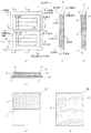
図19は、一般的な配送ラベルの一例を示す図であり、(a)は正面図、(b)は(a)に示したA−A’断面図、(c)は(a)に示したB−B’断面図、(d)は上基材510の裏面の構成を示す図、(e)は下基材520の表面の構成を示す図である。   FIG. 19 is a diagram illustrating an example of a general delivery label, where (a) is a front view, (b) is a cross-sectional view taken along line AA ′ shown in (a), and (c) is shown in (a). BB 'sectional drawing, (d) is a figure which shows the structure of the back surface of the upper base material 510, (e) is a figure which shows the structure of the surface of the lower base material 520.

本例は図19に示すように、剥離紙530上に下基材520と上基材510とが積層されて構成された配送ラベル501である。   As shown in FIG. 19, this example is a delivery label 501 configured by laminating a lower base material 520 and an upper base material 510 on a release paper 530.

剥離紙530は、剥離台紙531の一方の面に剥離剤532が塗工されることによって構成されている。この剥離紙530の剥離剤532が塗工された面に下基材520が積層され、下基材520の裏面に塗工された粘着剤542によって下基材520が剥離紙530に剥離可能に貼着されている。   The release paper 530 is configured by applying a release agent 532 to one surface of the release mount 531. The lower base material 520 is laminated on the surface of the release paper 530 on which the release agent 532 is applied, and the lower base material 520 can be peeled off from the release paper 530 by the adhesive 542 applied to the back surface of the lower base material 520. It is stuck.

上基材510は、配達票511と貼付票512とがスリット513を介して連接して構成されている。配達票511及び貼付票512のそれぞれには、この配送ラベル501が貼着されて配送される配送物の配送元及び配送先の住所や氏名あるいは名称等の配送情報が印字される配送情報印字領域511a,512aが設けられている。また、配達票511には、この配送ラベル501が貼着されて配送される配送物の配送先にて受領印を押下するための押印領域511bが設けられている。   The upper base material 510 is configured such that a delivery slip 511 and a sticker slip 512 are connected via a slit 513. In each of the delivery slip 511 and the sticker slip 512, a delivery information printing area in which delivery information such as an address, a name or a name of a delivery source and a delivery destination of a delivery to be delivered with the delivery label 501 attached is printed. 511a and 512a are provided. In addition, the delivery slip 511 is provided with a stamp area 511b for pressing a receipt stamp at a delivery destination of a delivery item to which the delivery label 501 is attached and delivered.

下基材520の表面にはその全面に粘着剤541が塗工されており、この粘着剤541によって下基材520に上基材510が貼着されているが、上基材510のうち配達票511の裏面にはその全面に剥離剤550が塗工されており、それにより、配達票511は下基材520に剥離可能に貼着されている。そして、配達票511の角部の1つを含む領域が、下基材520から配達票511を剥離する際の剥離開始端部511cとなっている。   An adhesive 541 is applied to the entire surface of the lower substrate 520, and the upper substrate 510 is attached to the lower substrate 520 by this adhesive 541. A release agent 550 is applied to the entire back surface of the vote 511, whereby the delivery slip 511 is detachably attached to the lower substrate 520. A region including one of the corners of the delivery slip 511 is a peeling start end portion 511c when peeling the delivery slip 511 from the lower base material 520.

以下に、上記のように構成された配送ラベル501の使用方法について説明する。   Below, the usage method of the delivery label 501 comprised as mentioned above is demonstrated.

図20は、図19に示した配送ラベル501の使用方法を説明するための図である。   FIG. 20 is a diagram for explaining a method of using the delivery label 501 shown in FIG.

図19に示した配送ラベル501は、まず、図20(a)に示すように、配達票511及び貼付票512のそれぞれに設けられた配送情報印字領域511a,512aに、この配送ラベル501が貼着されて配送される配送物の配送元及び配送先の住所や氏名あるいは名称等の配送情報511d,512dが印字された後、下基材520が剥離紙530から剥離される。   As shown in FIG. 20A, the delivery label 501 shown in FIG. 19 is first attached to the delivery information print areas 511a and 512a provided in the delivery slip 511 and the sticker slip 512, respectively. After the delivery information 511d and 512d such as the address and name or name of the delivery source and delivery destination of the delivery to be delivered is printed, the lower substrate 520 is peeled from the release paper 530.

下基材520が剥離紙530から剥離された配送ラベル501は、下基材520の裏面に塗工された粘着剤542が表出し、図20(b)に示すように、この粘着剤542によって配送物502に貼着される。   The delivery label 501 from which the lower base material 520 is peeled off from the release paper 530 is exposed to the adhesive 542 applied to the back surface of the lower base material 520. As shown in FIG. Affixed to delivery item 502.

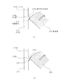
配送ラベル501が貼着された配送物502が、配送情報印字領域511a,512aに印字された配送情報511d,512dに従って配送先に届けられると、配達票511の押印領域511bに受領印が押下され、図20(c),(d)に示すように、配達票511が、剥離開始端部511cを剥離開始端として下基材520から剥離され、配送ラベル501から分離される。配達票511は、裏面に剥離剤550が塗工されていることにより下基材520から剥離できるとともに、貼付票512とはスリット513を介して連接しているため、配送ラベル501から分離することができる。   When the delivery item 502 to which the delivery label 501 is attached is delivered to the delivery destination in accordance with the delivery information 511d and 512d printed in the delivery information print areas 511a and 512a, the receipt stamp is pressed in the seal area 511b of the delivery slip 511. 20C and 20D, the delivery slip 511 is peeled from the lower base material 520 with the peeling start end 511c as the peeling start end, and separated from the delivery label 501. The delivery slip 511 can be peeled from the lower base material 520 by applying the release agent 550 on the back surface, and is separated from the delivery label 501 because it is connected to the sticker slip 512 via the slit 513. Can do.

このように配送ラベル501から分離した配達票511は、配送業者等にて持ち帰られることになる。   Thus, the delivery slip 511 separated from the delivery label 501 is taken home by a delivery company or the like.

上述した配送ラベル501においては、配送物502の配送先にて押印領域511bに受領印が押下された後、配達票511が、剥離開始端部511cを剥離開始端として下基材520から剥離されることになるため、剥離開始端部511cが下基材520から剥離しやすい構造であることが好ましい。   In the delivery label 501 described above, after the receipt stamp is pressed on the stamp area 511b at the delivery destination of the delivery item 502, the delivery slip 511 is peeled from the lower base material 520 with the peeling start end 511c as the peeling start end. Therefore, it is preferable that the peeling start end portion 511c has a structure that is easy to peel from the lower base material 520.

ここで、伝票基材が粘着層によって剥離紙に剥離可能に貼着されて構成され、伝票基材にスリットによってラベルが分離可能に設けられたラベル付き配送伝票において、ラベルの一部に粘着層を設けないことで、ラベルを剥離紙から容易に剥離できるようにした構成が、例えば特許文献1に開示されている。   Here, in the delivery slip with a label in which the slip base material is configured to be peelable and adhered to the release paper by the adhesive layer, and the label is provided on the slip base material so that the label can be separated by the slit, the adhesive layer is attached to a part of the label. For example, Patent Document 1 discloses a configuration in which the label can be easily peeled off from the release paper by not providing the label.

この構成を上述した配送ラベル501に適用し、下基材520の表面のうち、剥離開始端部511cに対向する領域に粘着剤541を塗工しない構成とすることにより、配達票511を下基材520から容易に剥離することができるようになる。   This configuration is applied to the delivery label 501 described above, and the adhesive slip 541 is not applied to a region of the surface of the lower base material 520 facing the peeling start end portion 511c, whereby the delivery slip 511 is set to the lower base. It can be easily peeled from the material 520.

特開2002−175014号公報JP 2002-175014 A

ところで、上述したように、配達票511及び貼付票512のそれぞれに設けられた配送情報印字領域511a,512aには、この配送ラベル501が貼着されて配送される配送物の配送元及び配送先の住所や氏名あるいは名称等の配送情報511d,512dが印字されることになるが、その際、配送ラベル501がプリンタ内を搬送されることになる。   By the way, as described above, in the delivery information print areas 511a and 512a provided in the delivery slip 511 and the sticker slip 512, the delivery source and the delivery destination of the delivery items to which the delivery label 501 is attached are delivered. The delivery information 511d, 512d such as the address, name, or name is printed, and the delivery label 501 is conveyed in the printer.

そのため、スリット513に接する領域において上基材510と下基材520とが貼着されていない部分が存在すると、その部分から上基材510が捲れ上がり、プリンタ内にて上基材510と下基材520とが剥離してしまい、紙づまり等が発生してしまう虞れがある。特に、配達票511を下基材520から剥離しやすくするためには、スリットに接する領域において上基材510と下基材520とが貼着されていない部分の面積を広くすることが好ましいが、その面積を広くするほど、上基材510が捲れ上がり、プリンタ内にて上基材510と下基材520とが剥離してしまう可能性が高くなってしまう。   For this reason, if there is a portion where the upper base material 510 and the lower base material 520 are not attached to each other in a region in contact with the slit 513, the upper base material 510 is rolled up from the portion, and the upper base material 510 and the lower base material 520 are laid in the printer. The substrate 520 may be peeled off and a paper jam or the like may occur. In particular, in order to make it easy to peel the delivery slip 511 from the lower base material 520, it is preferable to increase the area of the portion where the upper base material 510 and the lower base material 520 are not attached in the region in contact with the slit. As the area is increased, the upper base material 510 is rolled up, and the possibility that the upper base material 510 and the lower base material 520 are separated in the printer increases.

本発明は、上述したような従来の技術が有する問題点に鑑みてなされたものであって、その一部が剥離可能となるように貼着された2枚のシートを有するラベルにおいて、2枚のシートの一部を剥離しやすくしながらも、プリンタにて搬送する際等にて2枚のシートが不用意に剥離してしまうことを回避することができるラベルを提供することを目的とする。   The present invention has been made in view of the problems of the conventional technology as described above, and in a label having two sheets attached so that a part thereof can be peeled, two sheets are provided. An object of the present invention is to provide a label capable of avoiding that two sheets are inadvertently peeled off when being conveyed by a printer while easily peeling a part of the sheet. .

上記目的を達成するために本発明は、
第1の領域と第2の領域とが、連続した第1の切り離し線を介して連接した第1のシートと、
前記第1のシートの一方の面に貼着され、前記第1のシートとの貼着面とは反対側の面に粘着層を具備する第2のシートと、
前記粘着層によって第2のシートに剥離可能に貼着された第3のシートとを有し、
前記第1のシートが、前記第1の領域が前記第2のシートから剥離可能に構成されるとともに、前記第1の領域のうち、前記第1の切り離し線に沿う領域にて当該第1の領域の1つの角部を含むように設けられ、該第1の領域の前記第2のシートからの剥離を開始する剥離開始端部が、前記第2のシートに貼着されていない非貼着部となっており、前記第2のシートから前記第3のシートが剥離されて前記粘着層によって被着体に貼着されて使用されるラベルにおいて、
前記第1、第2及び第3のシートは、前記第1の領域と前記第2の領域との連接方向に直交する方向に、前記剥離開始端部を含む辺から延設した延設部を有し、
前記第1及び第2のシートは、前記剥離開始端部を含む辺に、連続した第2の切り離し線を有し、
前記第1の切り離し線が、前記非貼着部においてタイ部とスリット部と斜め切り込み部とからなり、
前記斜め切り込み部は、前記タイ部の前記剥離開始端部とは反対側に隣接するスリット部の端部から連続し、該スリット部に対して前記第1の領域の内部に鈍角を有して斜めに延び、
前記第1のシートにおいて、前記第2の切り離し線が前記非貼着部にてマイクロミシンから構成されていることを特徴とする。
In order to achieve the above object, the present invention provides:
A first sheet in which the first region and the second region are connected via a continuous first separation line;
A second sheet that is adhered to one surface of the first sheet, and includes an adhesive layer on the surface opposite to the adhesion surface to the first sheet;
Having a third sheet releasably attached to the second sheet by the adhesive layer;
The first sheet is configured such that the first region can be peeled from the second sheet, and the first sheet is formed in a region along the first separation line in the first region. Non-sticking that is provided so as to include one corner of a region, and a peeling start end portion that starts peeling of the first region from the second sheet is not stuck to the second sheet In the label used by being attached to an adherend by the adhesive layer by peeling the third sheet from the second sheet,
The first sheet, the second sheet, and the third sheet include an extending portion that extends from a side including the peeling start end portion in a direction orthogonal to a connecting direction between the first region and the second region. Have
The first and second sheets have a continuous second separation line on a side including the peeling start end,
The first separation line is composed of a tie portion, a slit portion, and an oblique cut portion in the non-sticking portion,
The oblique cut portion is continuous from an end portion of the slit portion adjacent to the side opposite to the peeling start end portion of the tie portion, and has an obtuse angle inside the first region with respect to the slit portion. Extending diagonally,
In the first sheet, the second separation line is constituted by a micro sewing machine at the non-sticking portion .

上記のように構成された本発明においては、第1のシートの第1の領域を第2のシートから剥離する際、第1の領域のうち剥離開始端部が第2のシートに貼着されていない非貼着部となっていることにより、剥離開始端部を剥離開始端として第1の領域を第2のシートから剥離しやすくなっている。また、第1の領域は、第2のシートから剥離可能に構成されるとともに、第2の領域とは、連続した第1の切り離し線を介して連接していることにより、第1のシートのうち第1の領域のみを第2のシートから剥離することができるが、第1の切り離し線が、非貼着部にて部分的に途切れていることにより、非貼着部においても、第1の領域の一部が、第2のシートに貼着されている第2の領域に固定されていることになり、プリンタにて搬送する際等にて第1のシートと第2のシートとが不用意に剥離してしまうことが回避されることになる。   In this invention comprised as mentioned above, when peeling the 1st area | region of a 1st sheet | seat from a 2nd sheet | seat, a peeling start edge part is stuck to a 2nd sheet | seat among 1st area | regions. By becoming the non-sticking part which is not, the 1st area | region is easy to peel from a 2nd sheet | seat by making a peeling start edge part into a peeling start edge. The first region is configured to be peelable from the second sheet, and the second region is connected to the second region via a continuous first separation line. Of these, only the first region can be peeled from the second sheet, but the first detachment line is partially interrupted at the non-sticking portion, so that the first non-sticking portion also has the first. A part of the area is fixed to the second area adhered to the second sheet, and the first sheet and the second sheet are separated when being conveyed by the printer. Inadvertent peeling is avoided.

また、非貼着部としては、第1の領域の角部のうち剥離開始端部を含む角部を頂点とした二等辺三角形の形状を有し、該二等辺三角形の等辺の長さが10mm以上のものが考えられ、その場合、第1の切り離し線が途切れた部分の長さが、2mm以下であれば好ましい。   Further, as the non-sticking part, it has an isosceles triangle shape with the corner including the peeling start end as a vertex among the corners of the first region, and the length of the isosceles triangle is 10 mm. The above can be considered. In this case, it is preferable that the length of the portion where the first separation line is interrupted is 2 mm or less.

また、第1、第2及び第3のシートが、第1の領域と第2の領域との連接方向に直交する方向に、剥離開始端部を含む辺から延設した延設部を有し、第1及び第2のシートが、剥離開始端部を含む辺に、連続した第2の切り離し線を有する構成において、第2の切り離し線が、非貼着部にて部分的に途切れていることで、上記同様に、第1の領域を第2のシートから剥離しやすくしながらも、プリンタにて搬送する際等にて第1のシートと第2のシートとが不用意に剥離してしまうことが回避されることになる。 In addition, the first, second, and third sheets have an extending portion that extends from a side including the peeling start end portion in a direction orthogonal to the connecting direction of the first region and the second region. , first and second sheets, the side including the peel starting end portion, in a configuration having a second separation line continuous, second disconnecting lines, that have partially broken in a non-adhesive portion As described above, the first sheet and the second sheet are inadvertently peeled off when transported by a printer, etc., while the first area is easily peeled off from the second sheet. It will be avoided.

本発明によれば、第1の領域を第2のシートから剥離しやすくするための非貼着部にて、第1の領域と第2の領域とが連接している第1の切り離し線が部分的に途切れている構成としたため、第1のシートのうち第1の領域を第2のシートから剥離しやすくしながらも、プリンタにて搬送する際等において、第1のシートと第2のシートとが不用意に剥離してしまうことを回避することができる。   According to the present invention, the first separation line in which the first region and the second region are connected to each other in the non-sticking portion for facilitating the separation of the first region from the second sheet. Since the configuration is partially interrupted, the first region of the first sheet can be easily separated from the second sheet, but the first sheet and the second sheet can be easily transported by the printer. It is possible to avoid inadvertent peeling from the sheet.

本発明のラベルの第1の実施の形態を示す図であり、(a)は正面図、(b)は(a)に示したA−A’断面図、(c)は(a)に示したB−B’断面図、(d)は(a)に示したC−C’断面図、(e)は上基材の裏面の構成を示す図、(f)は下基材の表面の構成を示す図である。It is a figure which shows 1st Embodiment of the label of this invention, (a) is a front view, (b) is AA 'sectional drawing shown to (a), (c) is shown to (a). BB 'sectional view, (d) is a CC' sectional view shown in (a), (e) is a diagram showing the configuration of the back surface of the upper substrate, and (f) is the surface of the lower substrate. It is a figure which shows a structure. 図1に示した剥離開始端部の詳細な構成を示す図である。It is a figure which shows the detailed structure of the peeling start edge part shown in FIG. 図1に示した配送ラベルの作用を説明するための図である。It is a figure for demonstrating the effect | action of the delivery label shown in FIG. 図1に示した配送ラベルの使用方法を説明するための図である。It is a figure for demonstrating the usage method of the delivery label shown in FIG. 図1に示した配達票が貼付票から分離していく様子を説明するための図である。It is a figure for demonstrating a mode that the delivery slip shown in FIG. 1 isolate | separates from a sticker slip. 本発明のラベルの第2の実施の形態を示す図であり、(a)は正面図、(b)は(a)に示したA−A’断面図、(c)は(a)に示したB−B’断面図、(d)は(a)に示したC−C’断面図、(e)は上基材の裏面の構成を示す図、(f)は下基材の表面の構成を示す図である。It is a figure which shows 2nd Embodiment of the label of this invention, (a) is a front view, (b) is AA 'sectional drawing shown to (a), (c) is shown to (a). BB 'sectional view, (d) is a CC' sectional view shown in (a), (e) is a diagram showing the configuration of the back surface of the upper substrate, and (f) is the surface of the lower substrate. It is a figure which shows a structure. 図6に示した剥離開始端部の詳細な構成を示す図である。It is a figure which shows the detailed structure of the peeling start edge part shown in FIG. 図6に示した配送ラベルの作用を説明するための図である。It is a figure for demonstrating the effect | action of the delivery label shown in FIG. 図6に示した配送ラベルの使用方法を説明するための図である。It is a figure for demonstrating the usage method of the delivery label shown in FIG. 本発明のラベルの第3の実施の形態を示す図であり、(a)は正面図、(b)は(a)に示したA−A’断面図、(c)は(a)に示したB−B’断面図、(d)は上基材の裏面の構成を示す図、(e)は下基材の表面の構成を示す図である。It is a figure which shows 3rd Embodiment of the label of this invention, (a) is a front view, (b) is AA 'sectional drawing shown to (a), (c) is shown to (a). BB 'sectional drawing, (d) is a figure which shows the structure of the back surface of an upper base material, (e) is a figure which shows the structure of the surface of a lower base material. 図10に示した剥離開始端部の詳細な構成を示す図である。It is a figure which shows the detailed structure of the peeling start edge part shown in FIG. 図10に示した配送ラベルシートの作用を説明するための図である。It is a figure for demonstrating an effect | action of the delivery label sheet | seat shown in FIG. 図10に示した配送ラベルシートの使用方法を説明するための図である。It is a figure for demonstrating the usage method of the delivery label sheet | seat shown in FIG. 図13に示した配送ラベルがスタブから分離していく様子を説明するための図である。It is a figure for demonstrating a mode that the delivery label shown in FIG. 13 isolate | separates from a stub. 本発明のラベルの第4の実施の形態を示す図であり、(a)は正面図、(b)は(a)に示したA−A’断面図、(c)は(a)に示したB−B’断面図、(d)は上基材の裏面の構成を示す図、(e)は下基材の表面の構成を示す図である。It is a figure which shows 4th Embodiment of the label of this invention, (a) is a front view, (b) is AA 'sectional drawing shown to (a), (c) is shown to (a). BB 'sectional drawing, (d) is a figure which shows the structure of the back surface of an upper base material, (e) is a figure which shows the structure of the surface of a lower base material. 図15に示した剥離開始端部の詳細な構成を示す図である。It is a figure which shows the detailed structure of the peeling start end part shown in FIG. 図15に示した配送ラベルシートの作用を説明するための図である。It is a figure for demonstrating an effect | action of the delivery label sheet | seat shown in FIG. 図15に示した配送ラベルシートの使用方法を説明するための図である。It is a figure for demonstrating the usage method of the delivery label sheet | seat shown in FIG. 一般的な配送ラベルの一例を示す図であり、(a)は正面図、(b)は(a)に示したA−A’断面図、(c)は(a)に示したB−B’断面図、(d)は上基材の裏面の構成を示す図、(e)は下基材の表面の構成を示す図である。It is a figure which shows an example of a general delivery label, (a) is a front view, (b) is AA 'sectional drawing shown to (a), (c) is BB shown to (a). 'Cross sectional view, (d) is a diagram showing the configuration of the back surface of the upper substrate, and (e) is a diagram showing the configuration of the surface of the lower substrate. 図19に示した配送ラベルの使用方法を説明するための図である。It is a figure for demonstrating the usage method of the delivery label shown in FIG.

以下に、本発明の実施の形態について図面を参照して説明する。   Embodiments of the present invention will be described below with reference to the drawings.

(第1の実施の形態)
図1は、本発明のラベルの第1の実施の形態を示す図であり、(a)は正面図、(b)は(a)に示したA−A’断面図、(c)は(a)に示したB−B’断面図、(d)は(a)に示したC−C’断面図、(e)は上基材10の裏面の構成を示す図、(f)は下基材20の表面の構成を示す図である。
(First embodiment)
1A and 1B are diagrams showing a first embodiment of a label of the present invention, in which FIG. 1A is a front view, FIG. 1B is a cross-sectional view taken along the line AA ′ shown in FIG. BB 'sectional drawing shown to a), (d) is CC' sectional drawing shown to (a), (e) is a figure which shows the structure of the back surface of the upper base material 10, (f) is lower 2 is a diagram illustrating a configuration of a surface of a base material 20. FIG.

本形態は図1に示すように、第3のシートである剥離紙30上に、第2のシートである下基材20と、第1のシートである上基材10とが積層されて構成された配送ラベル1である。上基材10と下基材20とは同一形状を有し、剥離紙30は、それよりも一回り大きな形状となっている。   In this embodiment, as shown in FIG. 1, a lower base material 20 that is a second sheet and an upper base material 10 that is a first sheet are laminated on a release paper 30 that is a third sheet. The delivery label 1 is displayed. The upper base material 10 and the lower base material 20 have the same shape, and the release paper 30 has a shape slightly larger than that.

剥離紙30は、剥離台紙31の一方の面に剥離剤32が塗工されることによって構成されている。この剥離紙30の剥離剤32が塗工された面に下基材20が積層され、下基材20の裏面に塗工された粘着層を構成する粘着剤42によって下基材20が剥離紙30に剥離可能に貼着されている。   The release paper 30 is configured by coating a release agent 32 on one surface of a release mount 31. The lower substrate 20 is laminated on the surface of the release paper 30 to which the release agent 32 is applied, and the lower substrate 20 is released by the adhesive 42 constituting the adhesive layer applied to the back surface of the lower substrate 20. 30 is attached to be peelable.

上基材10は、第1の領域である配達票11と、第2の領域である貼付票12とが、連続した第1の切り離し線であるスリット13を介して連接して構成されている。配達票11及び貼付票12のそれぞれには、この配送ラベル1が貼着されて配送される配送物の配送元及び配送先の住所や氏名あるいは名称等の配送情報が印字される配送情報印字領域11a,12aが設けられている。また、配達票11には、この配送ラベル1が貼着されて配送される配送物の配送先にて受領印を押下するための押印領域11bが設けられている。   The upper base material 10 is configured such that a delivery slip 11 which is a first region and a sticker slip 12 which is a second region are connected via a slit 13 which is a continuous first separation line. . In each of the delivery slip 11 and the sticker slip 12, a delivery information printing area in which delivery information such as the address, name or name of the delivery source and delivery destination of the delivery to be delivered with the delivery label 1 attached is printed. 11a and 12a are provided. Further, the delivery slip 11 is provided with a stamp area 11b for pressing a receipt stamp at a delivery destination of a delivery item to which the delivery label 1 is attached and delivered.

上基材10は、配達票11の裏面の全面に剥離剤50が塗工されており、それにより、配達票11が下基材20から剥離可能に構成されている。配達票11は、その角部の1つを含む領域が、下基材20からの配達票11の剥離を開始する剥離開始端部11cとなっている。   The upper base material 10 is configured such that the release agent 50 is coated on the entire back surface of the delivery form 11, and the delivery form 11 can be peeled from the lower base material 20. In the delivery slip 11, a region including one of the corners is a peeling start end portion 11 c that starts peeling of the delivery slip 11 from the lower base material 20.

下基材20の表面においては、剥離開始端部11cに対向する領域が、非貼着部であるのり抜き部15となっており、のり抜き部15を除く全面に粘着剤41が塗工され、この粘着剤41によって下基材20に上基材10が貼着されている。   On the surface of the lower base material 20, a region facing the peeling start end portion 11 c is a non-sticking portion 15 that is a paste portion 15, and the adhesive 41 is applied to the entire surface except the paste portion 15. The upper base material 10 is adhered to the lower base material 20 by the adhesive 41.

これにより、上基材10のうち配達票11が下基材20に剥離可能に貼着され、さらに、配達票11のうち剥離開始端部11cが下基材20に貼着されていない構成となっている。   Thereby, the delivery slip 11 of the upper base material 10 is detachably attached to the lower base material 20, and the peeling start end portion 11 c of the delivery slip 11 is not attached to the lower base material 20. It has become.

また、配達票11と貼付票12とは、スリット13を介して連接しているが、剥離開始端部11cの一部には、スリット13の代わりにジッパー部14が設けられている。   The delivery slip 11 and the sticker slip 12 are connected via a slit 13, but a zipper portion 14 is provided in place of the slit 13 at a part of the peeling start end portion 11 c.

ここで、剥離開始端部11cの詳細な構成について詳細に説明する。   Here, the detailed configuration of the peeling start end portion 11c will be described in detail.

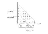
図2は、図1に示した剥離開始端部11cの詳細な構成を示す図である。   FIG. 2 is a diagram showing a detailed configuration of the peeling start end portion 11c shown in FIG.

図2に示すように、下基材20の表面においては、剥離開始端部11cに対向する領域が、非貼着部であるのり抜き部15(図中「×」で示す)となっている。また、その一部に、スリット13の代わりにジッパー部14が設けられている。   As shown in FIG. 2, in the surface of the lower base material 20, the area | region which opposes the peeling start end part 11c becomes the paste part 15 (it shows with "x" in a figure) which is a non-sticking part. . In addition, a zipper part 14 is provided instead of the slit 13 in a part thereof.

ジッパー部14は、配達票11と貼付票12とがスリット13を介さずに連接したタイ部14bと、タイ部14bの剥離開始端部11cを含む角部とは反対側に隣接するスリット13の端部から連続し、配達票11の内部に鈍角を有して斜めに延びた斜め切り込み部14aとから構成されている。   The zipper portion 14 includes a tie portion 14b in which the delivery slip 11 and the sticker slip 12 are connected to each other without the slit 13, and a slit 13 adjacent to the opposite side of the corner portion including the peeling start end portion 11c of the tie portion 14b. Continuing from the end portion, the delivery slip 11 has an oblique cut portion 14a that has an obtuse angle and extends obliquely.

のり抜き部15は、配達票11の角部のうち剥離開始端部11cを含む角部を頂点とした二等辺三角形の形状を有している。そして、剥離開始端部11cを含む角部からタイ部14bまでの長さaが5mm、タイ部14bの長さbが2mm、のり抜き部15の等辺の長さcが15mm程度となっている。   The glued portion 15 has an isosceles triangle shape with the corner portion including the peeling start end portion 11 c among the corner portions of the delivery slip 11 as a vertex. The length a from the corner including the peeling start end portion 11c to the tie portion 14b is 5 mm, the length b of the tie portion 14b is 2 mm, and the length c of the equilateral side of the scraped portion 15 is about 15 mm. .

これにより、スリット13は、のり抜き部15にて部分的に途切れた構成となっており、このスリット13が途切れた部分に、タイ部14bと斜め切り込み部14aとからなるジッパー部14が設けられていることになる。すなわち、スリット13が途切れた部分には、配達票11と貼付票12とがスリット13を介さずに連接した連続部となるタイ部14bと、スリット13が途切れた2つの端部のうち、配達票11の剥離開始端部11cを含む角部から遠い側の端部から連続し、スリット13に対して配達票11の内部に鈍角を有して斜めに延びた切り込み部となる斜め切り込み部14aとが設けられていることになる。なお、タイ部14bの長さbは2mm以下、のり抜き部15の等辺の長さcは10mm以上が好ましい。   As a result, the slit 13 has a structure in which the slit portion 15 is partially interrupted, and a zipper portion 14 including a tie portion 14b and an oblique cut portion 14a is provided in the portion where the slit 13 is interrupted. Will be. That is, in the portion where the slit 13 is interrupted, a delivery tie portion 14b that is a continuous portion in which the delivery slip 11 and the sticker slip 12 are connected without passing through the slit 13 and the two ends where the slit 13 is interrupted are delivered. An oblique cut portion 14a which is continuous from an end portion far from the corner portion including the peeling start end portion 11c of the slip 11 and becomes an oblique cut portion having an obtuse angle inside the delivery slip 11 with respect to the slit 13 and extending obliquely. And will be provided. In addition, the length b of the tie portion 14b is preferably 2 mm or less, and the length c of the equal side of the scraped portion 15 is preferably 10 mm or more.

以下に、上記のように構成された配送ラベル1の作用について説明する。   Below, the effect | action of the delivery label 1 comprised as mentioned above is demonstrated.

図3は、図1に示した配送ラベル1の作用を説明するための図であり、のり抜き部15近傍の断面を示す。なお、図3においては、剥離紙30の構成及び粘着剤42の図示は省略している。   FIG. 3 is a view for explaining the operation of the delivery label 1 shown in FIG. 1 and shows a cross section near the scraped portion 15. In addition, in FIG. 3, illustration of the structure of the release paper 30 and the adhesive 42 is abbreviate | omitted.

上述したように、図1に示した配送ラベル1においては、配達票11及び貼付票12のそれぞれに設けられた配送情報印字領域11a,12aに、この配送ラベル1が貼着されて配送される配送物の配送元及び配送先の住所や氏名あるいは名称等の配送情報11d,12dが印字される際、プリンタ内を搬送されることになる。なお、図1に示した配送ラベル1は、プリンタ内において配達票11と貼付票12の連接方向に搬送されるものとする。   As described above, in the delivery label 1 shown in FIG. 1, the delivery label 1 is attached and delivered to the delivery information print areas 11a and 12a provided in the delivery slip 11 and the sticker slip 12, respectively. When the delivery information 11d, 12d such as the address, name or name of the delivery source and delivery destination of the delivery is printed, it is conveyed in the printer. The delivery label 1 shown in FIG. 1 is conveyed in the connecting direction of the delivery slip 11 and the sticker 12 within the printer.

ここで、配達票11のうち剥離開始端部11cは、のり抜き部15となっていることから下基材20に貼着されていないため、プリンタ内を搬送された場合、スリット13から捲れ上がってしまう虞れがある。ところが、図1に示した配送ラベル1は、上述したように、のり抜き部15の一部に、スリット13の代わりにジッパー部14が設けられているため、のり抜き部15においても、配達票11の剥離開始端部11cが、下基材20に貼着されている貼付票12にタイ部14bによって固定されていることになる。それにより、図3に示すように、例えば、プリンタ内にて湾曲しながら搬送された場合であっても、配達票11が捲れ上がることがなくなり、プリンタ内にて上基材10と下基材20とが剥離してしまうことが回避されることになる。   Here, since the peeling start end portion 11c of the delivery slip 11 is a paste portion 15 and is not attached to the lower base material 20, it is rolled up from the slit 13 when transported through the printer. There is a risk of it. However, since the delivery label 1 shown in FIG. 1 is provided with the zipper part 14 instead of the slit 13 in a part of the glue part 15 as described above, the delivery slip is also provided in the glue part 15. 11, the peeling start end portion 11 c is fixed to the sticker 12 attached to the lower base material 20 by the tie portion 14 b. As a result, as shown in FIG. 3, for example, even when the sheet is conveyed while being bent in the printer, the delivery slip 11 does not roll up, and the upper base material 10 and the lower base material are not raised in the printer. That is, it is avoided that 20 peels off.

以下に、上記のように構成された配送ラベル1の使用方法について説明する。   Below, the usage method of the delivery label 1 comprised as mentioned above is demonstrated.

図4は、図1に示した配送ラベル1の使用方法を説明するための図である。   FIG. 4 is a diagram for explaining a method of using the delivery label 1 shown in FIG.

図1に示した配送ラベル1は、まず、図4(a)に示すように、配達票11及び貼付票12のそれぞれに設けられた配送情報印字領域11a,12aに、この配送ラベル1が貼着されて配送される配送物の配送元及び配送先の住所や氏名あるいは名称等の配送情報11d,12dが印字された後、下基材20が剥離紙30から剥離される。なお、配送ラベル1に配送情報11d,12dが印字される際、上述したように、ジッパー部14によって上基材10の下基材20からの不用意な剥離が回避される。   First, as shown in FIG. 4A, the delivery label 1 shown in FIG. 1 is attached to the delivery information print areas 11a and 12a provided in the delivery slip 11 and the sticker slip 12, respectively. After the delivery information 11d, 12d such as the address and name or name of the delivery source and delivery destination of the delivery delivered and delivered is printed, the lower substrate 20 is peeled from the release paper 30. In addition, when the delivery information 11d and 12d are printed on the delivery label 1, the zipper portion 14 avoids inadvertent peeling from the lower base material 20 of the upper base material 10 as described above.

下基材20が剥離紙30から剥離された配送ラベル1は、下基材20の裏面に塗工された粘着剤42が表出し、図4(b)に示すように、この粘着剤42によって被着体である配送物2に貼着される。   In the delivery label 1 from which the lower base material 20 is peeled off from the release paper 30, the adhesive 42 applied to the back surface of the lower base material 20 is exposed, and as shown in FIG. It is affixed to the delivery 2 which is an adherend.

配送ラベル1が貼着された配送物2が、配送情報印字領域11a,12aに印字された配送情報11d,12dに従って配送先に届けられると、配達票11の押印領域11bに受領印が押下され、図4(c),(d)に示すように、配達票11が、剥離開始端部11cを剥離開始端として下基材20から剥離され、配送ラベル1から分離される。この際、剥離開始端部11cは、のり抜き部15となっていることから下基材20に貼着されていないため、剥離開始端部11cと下基材20との間に指を容易に挿入することができ、配達票11を下基材20から容易に剥離し始めることができる。ここで、剥離開始端部11cにおいては、ジッパー部14のタイ部14bが存在している。そのため、タイ部14bの位置が、剥離開始端部11cを含む角部に近すぎた場合、剥離開始端部11cと下基材20との間に指を挿入しにくくなってしまう。反対に、タイ部14bの位置が、剥離開始端部11cを含む角部から遠すぎた場合は、上述したように上基材10の下基材20からの不用意な剥離を回避する効果が得にくくなってしまう。このように、タイ部14bの位置は、トレードオフの関係となっているとも言えるため、上基材10や下基材20の材質や大きさ、また、施される処理等に応じて適宜設定することが好ましい。   When the delivery item 2 to which the delivery label 1 is attached is delivered to the delivery destination in accordance with the delivery information 11d and 12d printed in the delivery information print areas 11a and 12a, a receipt stamp is pressed in the seal area 11b of the delivery slip 11. 4 (c) and 4 (d), the delivery slip 11 is peeled from the lower substrate 20 with the peeling start end 11c as the peeling start end, and separated from the delivery label 1. At this time, since the peeling start end portion 11c is not affixed to the lower base material 20 because it is a scraped portion 15, a finger can be easily placed between the peeling start end portion 11c and the lower base material 20. The delivery slip 11 can be easily peeled off from the lower substrate 20. Here, the tie part 14b of the zipper part 14 exists in the peeling start end part 11c. Therefore, when the position of the tie portion 14b is too close to the corner including the peeling start end portion 11c, it becomes difficult to insert a finger between the peeling start end portion 11c and the lower base material 20. On the contrary, when the position of the tie portion 14b is too far from the corner including the peeling start end portion 11c, the effect of avoiding inadvertent peeling from the lower base material 20 of the upper base material 10 as described above. It becomes difficult to obtain. Thus, since the position of the tie portion 14b can be said to be in a trade-off relationship, the position is appropriately set according to the material and size of the upper base material 10 and the lower base material 20, processing to be performed, and the like. It is preferable to do.

図5は、図1に示した配達票11が貼付票12から分離していく様子を説明するための図である。   FIG. 5 is a diagram for explaining how the delivery slip 11 shown in FIG.

配達票11を、剥離開始端部11cを剥離開始端として下基材20から剥離しながら貼付票12から分離していき、配達票11と貼付票12との分離部分が、スリット13のうち剥離開始端部11cを含む角部から延びた部分のタイ部14b側の端部に達すると、図5(a)に示すように、配達票11が裂けてその破断部分16が配達票11の分離方向(図中右上に向かう方向)に延びていく。   The delivery slip 11 is separated from the sticking slip 12 while being peeled from the lower base material 20 with the peeling start end 11c as the peeling start end, and the separation portion between the delivery slip 11 and the sticking slip 12 is peeled off of the slit 13. When the end portion on the tie portion 14b side of the portion including the start end portion 11c is reached, the delivery slip 11 is torn and the broken portion 16 is separated from the delivery slip 11 as shown in FIG. It extends in the direction (the direction toward the upper right in the figure).

ところが、破断部分16が延びる方向には、ジッパー部14の斜め切り込み部14aが存在するため、図5(b)に示すように破断部分16がこの斜め切り込み部14aに繋がり、それにより、その後スリット13に沿って配達票11が貼付票12から分離することになる。   However, since there is an oblique cut portion 14a of the zipper portion 14 in the direction in which the broken portion 16 extends, the broken portion 16 is connected to the oblique cut portion 14a as shown in FIG. 13, the delivery slip 11 is separated from the sticker slip 12.

配送ラベル1から分離した配達票11は、配送業者等にて持ち帰られることになる。   The delivery slip 11 separated from the delivery label 1 is taken home by a delivery company or the like.

このように、本形態においては、配達票11の下基材20からの剥離を開始する剥離開始端部11cがのり抜き部15となって下基材20に貼着されておらず、剥離開始端部11cの一部に、配達票11と貼付票12とが連接しているスリット13の代わりに、タイ部14bを有するジッパー部14を設けたことにより、配達票11を下基材20から剥離しやすくしながらも、プリンタにて搬送する際等において、上基材10と下基材20とが不用意に剥離してしまうことを回避することができる。   As described above, in this embodiment, the peeling start end portion 11c that starts peeling from the lower base material 20 of the delivery slip 11 becomes the scraped portion 15 and is not attached to the lower base material 20, and starts peeling. A zipper part 14 having a tie part 14b is provided in a part of the end part 11c in place of the slit 13 in which the delivery form 11 and the sticking form 12 are connected to each other. While being easily peeled off, it is possible to avoid the upper base material 10 and the lower base material 20 from being carelessly peeled off when transported by a printer.

(第2の実施の形態)
図6は、本発明のラベルの第2の実施の形態を示す図であり、(a)は正面図、(b)は(a)に示したA−A’断面図、(c)は(a)に示したB−B’断面図、(d)は(a)に示したC−C’断面図、(e)は上基材110の裏面の構成を示す図、(f)は下基材120の表面の構成を示す図である。
(Second Embodiment)
6A and 6B are diagrams showing a second embodiment of the label of the present invention, in which FIG. 6A is a front view, FIG. 6B is a cross-sectional view taken along the line AA ′ shown in FIG. BB 'sectional drawing shown to a), (d) is CC' sectional drawing shown to (a), (e) is a figure which shows the structure of the back surface of the upper base material 110, (f) is lower It is a figure which shows the structure of the surface of the base material.

本形態は図6に示すように、第1の実施の形態に示したものに対して、ジッパー部14の代わりにマイクロミシン114が設けられている点のみが異なるものである。   As shown in FIG. 6, this embodiment is different from that shown in the first embodiment only in that a micro-sewing machine 114 is provided instead of the zipper portion 14.

図7は、図6に示した剥離開始端部111cの詳細な構成を示す図である。   FIG. 7 is a diagram showing a detailed configuration of the peeling start end portion 111c shown in FIG.

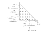
図7に示すように、下基材120の表面においては、剥離開始端部111cに対向する領域が、非貼着部であるのり抜き部115(図中「×」で示す)となっている。また、その一部に、スリット113の代わりにマイクロミシン114が設けられている。   As shown in FIG. 7, in the surface of the lower base material 120, the area | region which opposes the peeling start edge part 111c becomes the paste part 115 (it shows by "x" in a figure) which is a non-sticking part. . In addition, a micro sewing machine 114 is provided instead of the slit 113 in a part thereof.

マイクロミシン114は、細かな孔が微細な間隔で直線上に並んで構成されている。   The micro-sewing machine 114 is configured such that fine holes are arranged on a straight line at fine intervals.

のり抜き部115は、第1の実施の形態にて示したものと同様に、配達票111の角部のうち剥離開始端部111cを含む角部を頂点とした二等辺三角形の形状を有している。そして、剥離開始端部111cを含む角部からマイクロミシン114までの長さaが5mm、マイクロミシン114の長さbが2mm、のり抜き部115の等辺の長さcが15mm程度となっている。   The glued portion 115 has an isosceles triangle shape with the corner portion including the peeling start end portion 111c among the corner portions of the delivery slip 111 as an apex, similar to that shown in the first embodiment. ing. The length a from the corner including the peeling start end portion 111c to the micro sewing machine 114 is 5 mm, the length b of the micro sewing machine 114 is 2 mm, and the length c of the equilateral side of the scraped portion 115 is about 15 mm. .

このように、のり抜き部115にてスリット113の代わりにマイクロミシン114が設けられることにより、スリット113がのり抜き部115にて部分的に途切れた構成となっており、マイクロミシン114の2つの孔間において、配達票111と貼付票112とが繋がった状態となっている。なお、マイクロミシン114の長さbは2mm以下、のり抜き部115の等辺の長さcは10mm以上が好ましい。   Thus, by providing the micro sewing machine 114 in place of the slit 113 in the scraped portion 115, the slit 113 is partially cut off in the stripped portion 115. Between the holes, the delivery slip 111 and the sticker slip 112 are connected. The length b of the micro-sewing machine 114 is preferably 2 mm or less, and the length c of the equal side of the scraped portion 115 is preferably 10 mm or more.

以下に、上記のように構成された配送ラベル101の作用について説明する。   Hereinafter, the operation of the delivery label 101 configured as described above will be described.

図8は、図6に示した配送ラベル101の作用を説明するための図であり、のり抜き部115近傍の断面を示す。なお、図8においては、剥離紙130の構成及び粘着剤142の図示は省略している。   FIG. 8 is a view for explaining the operation of the delivery label 101 shown in FIG. 6 and shows a cross section near the scraped portion 115. In FIG. 8, the configuration of the release paper 130 and the illustration of the adhesive 142 are omitted.

図8に示した配送ラベル101においては、第1の実施の形態にて示したものと同様に、配達票111及び貼付票112のそれぞれに設けられた配送情報印字領域111a,112aに、この配送ラベル101が貼着されて配送される配送物の配送元及び配送先の住所や氏名あるいは名称等の配送情報111d,112dが印字される際、プリンタ内を搬送されることになる。なお、図8に示した配送ラベル101は、プリンタ内において配達票111と貼付票112の連接方向に搬送されるものとする。   In the delivery label 101 shown in FIG. 8, the delivery information print areas 111a and 112a provided in the delivery slip 111 and the sticker slip 112, respectively, are delivered to the delivery label 101 as in the first embodiment. When the delivery information 111d, 112d such as the address, name, or name of the delivery source and delivery destination of the delivery to be delivered with the label 101 attached is printed, it is conveyed in the printer. Note that the delivery label 101 shown in FIG. 8 is conveyed in the connection direction of the delivery slip 111 and the sticker 112 within the printer.

ここで、配達票111のうち剥離開始端部111cは、のり抜き部115となっていることから下基材120に貼着されていないため、プリンタ内を搬送された場合、スリット113から捲れ上がってしまう虞れがある。ところが、図8に示した配送ラベル101は、上述したように、のり抜き部115の一部に、スリット113の代わりにマイクロミシン114が設けられており、マイクロミシン114の2つの孔間において、配達票111と貼付票112とが繋がった状態となっているため、のり抜き部115においても、配達票111の剥離開始端部111cが、下基材120に貼着されている貼付票112に固定されていることになる。それにより、図8に示すように、例えば、プリンタ内にて湾曲しながら搬送された場合であっても、配達票111が捲れ上がることがなくなり、プリンタ内にて上基材110と下基材120とが剥離してしまうことが回避されることになる。   Here, in the delivery slip 111, the peeling start end portion 111c is not affixed to the lower base material 120 because it is a scraped portion 115. There is a risk of it. However, as described above, the delivery label 101 shown in FIG. 8 is provided with a micro sewing machine 114 instead of the slit 113 in a part of the scraped portion 115, and between the two holes of the micro sewing machine 114, Since the delivery slip 111 and the sticker 112 are in a connected state, the peeling start end portion 111 c of the delivery slip 111 is also attached to the sticker 112 attached to the lower substrate 120 in the glued portion 115. It will be fixed. As a result, as shown in FIG. 8, for example, even when the sheet is conveyed while curving in the printer, the delivery slip 111 does not roll up, and the upper base material 110 and the lower base material are not lifted in the printer. The separation from 120 is avoided.

以下に、上記のように構成された配送ラベル101の使用方法について説明する。   Below, the usage method of the delivery label 101 comprised as mentioned above is demonstrated.

図9は、図6に示した配送ラベル101の使用方法を説明するための図である。   FIG. 9 is a diagram for explaining a method of using the delivery label 101 shown in FIG.

図6に示した配送ラベル101は、まず、図9(a)に示すように、配達票111及び貼付票112のそれぞれに設けられた配送情報印字領域111a,112aに、この配送ラベル101が貼着されて配送される配送物の配送元及び配送先の住所や氏名あるいは名称等の配送情報111d,112dが印字された後、下基材120が剥離紙130から剥離される。なお、配送ラベル101に配送情報111d,112dが印字される際、上述したように、マイクロミシン114によって上基材110の下基材120からの不用意な剥離が回避される。   As shown in FIG. 9A, the delivery label 101 shown in FIG. 6 is first attached to the delivery information print areas 111a and 112a provided on the delivery slip 111 and the sticker slip 112, respectively. After the delivery information 111d, 112d such as the address and name or name of the delivery source and delivery destination of the delivery to be delivered is printed, the lower substrate 120 is peeled from the release paper 130. When the delivery information 111d and 112d are printed on the delivery label 101, the microsewing machine 114 avoids inadvertent peeling from the lower base 120 of the upper base 110 as described above.

下基材120が剥離紙130から剥離された配送ラベル101は、下基材120の裏面に塗工された粘着剤142が表出し、図9(b)に示すように、この粘着剤142によって配送物102に貼着される。   The delivery label 101 from which the lower base material 120 is peeled off from the release paper 130 is exposed with an adhesive 142 applied to the back surface of the lower base material 120. As shown in FIG. Affixed to the delivery item 102.

配送ラベル101が貼着された配送物102が、配送情報印字領域111a,112aに印字された配送情報111d,112dに従って配送先に届けられると、配達票111の押印領域111bに受領印が押下され、図9(c),(d)に示すように、配達票111が、剥離開始端部111cを剥離開始端として下基材120から剥離され、配送ラベル101から分離される。この際、剥離開始端部111cは、のり抜き部115となっていることから下基材120に貼着されていないため、剥離開始端部111cと下基材120との間に指を容易に挿入することができ、配達票111を下基材120から容易に剥離し始めることができる。ここで、剥離開始端部111cにおいては、マイクロミシン114が存在している。そのため、マイクロミシン114の位置が、剥離開始端部111cを含む角部に近すぎた場合、剥離開始端部111cと下基材120との間に指を挿入しにくくなってしまう。反対に、マイクロミシン114の位置が、剥離開始端部111cを含む角部から遠すぎた場合は、上述したように上基材110の下基材120からの不用意な剥離を回避する効果が得にくくなってしまう。このように、マイクロミシン114の位置は、トレードオフの関係となっているとも言えるため、上基材110や下基材120の材質や大きさ、また、施される処理等に応じて適宜設定することが好ましい。   When the delivery item 102 to which the delivery label 101 is attached is delivered to the delivery destination according to the delivery information 111d and 112d printed in the delivery information print areas 111a and 112a, a receipt stamp is pressed in the seal area 111b of the delivery slip 111. As shown in FIGS. 9C and 9D, the delivery slip 111 is peeled from the lower substrate 120 with the peeling start end 111c as the peeling start end, and separated from the delivery label 101. At this time, since the peeling start end portion 111c is not affixed to the lower base material 120 because it is a scraped portion 115, it is easy to place a finger between the peeling start end portion 111c and the lower base material 120. It can be inserted and the delivery slip 111 can be easily peeled off from the lower substrate 120. Here, the micro-sewing machine 114 is present at the peeling start end 111c. Therefore, if the position of the micro-sewing machine 114 is too close to the corner including the peeling start end portion 111 c, it becomes difficult to insert a finger between the peeling start end portion 111 c and the lower base material 120. On the other hand, when the position of the micro-sewing machine 114 is too far from the corner including the peeling start end portion 111c, the effect of avoiding inadvertent peeling from the lower base material 120 of the upper base material 110 as described above. It becomes difficult to obtain. Thus, since the position of the micro-sewing machine 114 can be said to be in a trade-off relationship, it is appropriately set according to the material and size of the upper base material 110 and the lower base material 120, processing to be performed, and the like. It is preferable to do.

配達票111を、剥離開始端部111cを剥離開始端として下基材120から剥離しながら貼付票112から分離していき、配達票111と貼付票112との分離部分が、スリット113のうち剥離開始端部111cを含む角部から延びた部分のマイクロミシン114側の端部に達すると、配達票111が配達票111の分離方向に裂けていこうとするが、マイクロミシン114は上述したように、細かな孔が微細な間隔で直線上に並んで構成されているため、細かな孔どうしが繋がり、それにより、配達票111が貼付票112から分離することになる。   The delivery slip 111 is separated from the sticker 112 while being peeled from the lower substrate 120 with the peel start end 111c as the peel start end, and the separation portion of the delivery slip 111 and the sticker 112 is peeled off the slit 113. When reaching the end of the part including the start end 111c on the side of the micro-sewing machine 114, the delivery slip 111 tries to tear in the separation direction of the delivery slip 111, but the micro-sewing machine 114 is as described above. Since the fine holes are arranged in a straight line at fine intervals, the fine holes are connected to each other, and the delivery slip 111 is separated from the sticker slip 112.

配送ラベル101から分離した配達票111は、配送業者等にて持ち帰られることになる。   The delivery slip 111 separated from the delivery label 101 is taken home by a delivery company or the like.

このように、本形態においては、配達票111の下基材120からの剥離を開始する剥離開始端部111cがのり抜き部115となって下基材120に貼着されておらず、剥離開始端部111cの一部に、配達票111と貼付票112とが連接しているスリット113の代わりに、マイクロミシン114を設けたことにより、配達票111を下基材120から剥離しやすくしながらも、プリンタにて搬送する際等において、上基材110と下基材120とが不用意に剥離してしまうことを回避することができる。   As described above, in this embodiment, the peeling start end portion 111c that starts peeling from the lower base material 120 of the delivery slip 111 is not affixed to the lower base material 120 as the scraped portion 115, and the peeling starts. By providing a micro-sewing machine 114 in place of the slit 113 where the delivery slip 111 and the sticking slip 112 are connected to a part of the end portion 111c, the delivery slip 111 can be easily peeled from the lower substrate 120. In addition, it is possible to avoid that the upper base material 110 and the lower base material 120 are inadvertently peeled off when transported by a printer.

(第3の実施の形態)
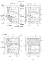
図10は、本発明のラベルの第3の実施の形態を示す図であり、(a)は正面図、(b)は(a)に示したA−A’断面図、(c)は(a)に示したB−B’断面図、(d)は上基材210の裏面の構成を示す図、(e)は下基材220の表面の構成を示す図である。
(Third embodiment)
10A and 10B are diagrams showing a third embodiment of the label of the present invention, in which FIG. 10A is a front view, FIG. 10B is a cross-sectional view taken along line AA ′ shown in FIG. BB 'sectional drawing shown to a), (d) is a figure which shows the structure of the back surface of the upper base material 210, (e) is a figure which shows the structure of the surface of the lower base material 220. FIG.

本形態は図10に示すように、第1の実施の形態にて示した配送ラベル201がマトリックス状に4つ並んで連接し、さらに、延設部となるスタブ217が連接してなる配送ラベルシート200である。   In this embodiment, as shown in FIG. 10, four delivery labels 201 shown in the first embodiment are connected in a matrix, and further, stubs 217 that are extended portions are connected. This is a sheet 200.

4つの配送ラベル201は、上基材210及び下基材220に形成されたスリット213bを介して連接している。   The four delivery labels 201 are connected via slits 213b formed in the upper base 210 and the lower base 220.

スタブ217は、2列に並んだ配送ラベル201のうち一方の列の2つの配送ラベル201の剥離開始端部211cを含む辺から、上基材210、下基材220及び剥離紙230が延設することで、2つの配送ラベル201に連接しており、この連接部分には、上基材210及び下基材220に第2の切り離し線となるスリット213bが形成されている。   In the stub 217, the upper substrate 210, the lower substrate 220, and the release paper 230 extend from the side including the peeling start end portion 211 c of the two delivery labels 201 in one row of the delivery labels 201 arranged in two rows. Thus, the two delivery labels 201 are connected to each other, and slits 213b serving as second separation lines are formed in the upper base material 210 and the lower base material 220 at the connection portion.

さらに、スリット213bは、剥離開始端部211cのそれぞれにて部分的に途切れており、その領域にはスリット213bの代わりにジッパー部218が設けられている。   Further, the slit 213b is partially interrupted at each of the peeling start end portions 211c, and a zipper portion 218 is provided in that region instead of the slit 213b.

図11は、図10に示した剥離開始端部211cの詳細な構成を示す図である。   FIG. 11 is a diagram showing a detailed configuration of the peeling start end portion 211c shown in FIG.

図11に示すように、下基材220の表面においては、剥離開始端部211cに対向する領域が、非貼着部であるのり抜き部215(図中「×」で示す)となっている。また、その一部に、スリット213a,213bの代わりにそれぞれジッパー部214,218が設けられている。   As shown in FIG. 11, on the surface of the lower base material 220, a region facing the peeling start end portion 211 c is a non-sticking portion 215 (indicated by “x” in the drawing). . In addition, zipper portions 214 and 218 are provided in part of them instead of the slits 213a and 213b.

ジッパー部214は、配達票211と貼付票212とがスリット213aを介さずに連接したタイ部214bと、タイ部214bの剥離開始端部211cを含む角部とは反対側に隣接するスリット213aの端部から連続し、配達票211の内部に鈍角を有して斜めに延びた斜め切り込み部214aとから構成されている。   The zipper portion 214 includes a tie portion 214b in which the delivery slip 211 and the sticker slip 212 are connected without passing through the slit 213a, and a slit 213a adjacent to the opposite side of the corner portion including the peeling start end portion 211c of the tie portion 214b. Continuing from the end portion, the delivery slip 211 has an oblique cut portion 214a that has an obtuse angle and extends obliquely.

ジッパー部218は、配達票211どうし及び下基材220の配達票211に対向する領域どうし、または配達票211及び下基材220の配達票211に対向する領域とスタブ217とがスリット213bを介さずに連接したタイ部218bと、タイ部218bの剥離開始端部211cを含む角部とは反対側に隣接するスリット213bの端部から連続し、配達票211の内部に鈍角を有して斜めに延びた斜め切り込み部218aとから構成されている。   In the zipper portion 218, the delivery slip 211 and the region facing the delivery slip 211 of the lower base material 220, or the region facing the delivery slip 211 and the delivery slip 211 of the lower base material 220 and the stub 217 via the slit 213b. The tie portion 218b connected without being connected to the end portion of the slit 213b adjacent to the opposite side of the corner portion including the peeling start end portion 211c of the tie portion 218b, has an obtuse angle inside the delivery slip 211, and is slanted. It is comprised from the diagonal cut | notch part 218a extended in this.

のり抜き部215は、配達票211の角部のうち剥離開始端部211cを含む角部を頂点とした二等辺三角形の形状を有しており、のり抜き部215の等辺の長さc,fが15mm程度となっている。また、剥離開始端部211cを含む角部からタイ部214bまでの長さaが5mm、タイ部214bの長さbが2mm程度となっており、剥離開始端部211cを含む角部からタイ部218bまでの長さdが3mm、タイ部218bの長さeが2mm程度となっている。   The glued portion 215 has an isosceles triangle shape with the corner including the peeling start end portion 211c among the corners of the delivery slip 211 as an apex, and the lengths c, f of the sides of the glued portion 215 are equal. Is about 15 mm. Further, the length a from the corner including the peeling start end 211c to the tie 214b is 5 mm, the length b of the tie 214b is about 2 mm, and the corner including the peeling start 211c is connected to the tie. The length d up to 218b is 3 mm, and the length e of the tie portion 218b is about 2 mm.

これにより、スリット213a,213bは、のり抜き部215にて部分的に途切れた構成となっており、このスリット213a,213bが途切れた部分に、タイ部214b,218bと斜め切り込み部214a,218aとからなるジッパー部214,218がそれぞれ設けられていることになる。すなわち、スリット213aが途切れた部分には、配達票211と貼付票212とがスリット213aを介さずに連接した連続部となるタイ部214bと、スリット213aが途切れた2つの端部のうち、配達票211の剥離開始端部211cを含む角部から遠い側の端部から連続し、スリット213aに対して配達票211の内部に鈍角を有して斜めに延びた切り込み部となる斜め切り込み部214aとが設けられていることになる。また、スリット213bが途切れた部分には、配達票211どうし及び下基材220の配達票211に対向する領域どうし、または配達票211及び下基材220の配達票211に対向する領域とスタブ217とがスリット213bを介さずに連接した連続部となるタイ部218bと、スリット213bが途切れた2つの端部のうち、配達票211の剥離開始端部211cを含む角部から遠い側の端部から連続し、スリット213bに対して配達票211の内部に鈍角を有して斜めに延びた切り込み部となる斜め切り込み部218aとが設けられていることになる。なお、タイ部214bの長さbは2mm以下、のり抜き部215の等辺の長さcは10mm以上が好ましい。   As a result, the slits 213a and 213b are partially cut off at the cut-out portion 215, and the tie portions 214b and 218b and the diagonal cut portions 214a and 218a Zipper portions 214 and 218 are provided. That is, in the part where the slit 213a is interrupted, the delivery form 211 and the sticking form 212 are connected to each other without the slit 213a, and the tie part 214b, which is a continuous part, and the two ends where the slit 213a is interrupted are delivered. An oblique cut portion 214a which is continuous from an end portion far from the corner including the peeling start end portion 211c of the slip 211 and becomes a cut portion having an obtuse angle inside the delivery slip 211 and extending obliquely with respect to the slit 213a. And will be provided. Further, in the portion where the slit 213b is interrupted, the areas facing the delivery slip 211 and the delivery slip 211 of the lower base material 220, or the region facing the delivery slip 211 and the delivery slip 211 of the lower base material 220, and the stub 217. Of the two ends where the slit 213b is interrupted, the end on the side far from the corner including the peeling start end 211c of the delivery slip 211. The slant cut portion 218a which is a cut portion having an obtuse angle and extending obliquely inside the delivery slip 211 with respect to the slit 213b is provided. In addition, the length b of the tie portion 214b is preferably 2 mm or less, and the length c of the equilateral side of the scraped portion 215 is preferably 10 mm or more.

以下に、上記のように構成された配送ラベルシート200の作用について説明する。   Below, the effect | action of the delivery label sheet | seat 200 comprised as mentioned above is demonstrated.

図12は、図10に示した配送ラベルシート200の作用を説明するための図であり、のり抜き部215近傍の断面を示す。なお、図12においては、剥離紙230の構成及び粘着剤242の図示は省略している。   FIG. 12 is a view for explaining the operation of the delivery label sheet 200 shown in FIG. 10 and shows a cross section near the scraped portion 215. In FIG. 12, the configuration of the release paper 230 and the adhesive 242 are not shown.

図10に示した配送ラベルシート200においては、第1の実施の形態にて示したものと同様に、配送ラベル201のそれぞれについて、配達票211及び貼付票212のそれぞれに設けられた配送情報印字領域211a,212aに、その配送ラベル201が貼着されて配送される配送物の配送元及び配送先の住所や氏名あるいは名称等の配送情報211d,212dが印字される際、プリンタ内を搬送されることになる。なお、図10に示した配送ラベルシート200は、プリンタ内において、スタブ217側が先端となって搬送されるものとする。   In the delivery label sheet 200 shown in FIG. 10, the delivery information printing provided on each of the delivery slip 211 and the sticker slip 212 for each of the delivery labels 201 is the same as that shown in the first embodiment. When the delivery information 211d, 212d such as the address, name or name of the delivery source and delivery destination of the delivery to be delivered with the delivery label 201 attached is printed in the areas 211a, 212a, it is conveyed within the printer. Will be. The delivery label sheet 200 shown in FIG. 10 is conveyed in the printer with the stub 217 side as the leading end.

ここで、配達票211のうち剥離開始端部211cは、のり抜き部215となっていることから下基材220に貼着されていないため、プリンタ内を搬送された場合、スタブ217との連接部分において、配達票211がスリット213bから捲れ上がってしまう虞れがある。ところが、図10に示した配送ラベルシート200は、上述したように、のり抜き部215の一部に、スリット213bの代わりにジッパー部218が設けられているため、のり抜き部215においても、配達票211の剥離開始端部211cが、スタブ217にタイ部218bによって固定されていることになる。それにより、図12(a)に示すように、例えば、プリンタ内にて湾曲しながら搬送された場合であっても、スタブ217との連接部分において、配達票211がスリット213bから捲れ上がることがなくなり、プリンタ内にて上基材210と下基材220とが剥離してしまうことが回避されることになる。   Here, in the delivery slip 211, the peeling start end portion 211c is not affixed to the lower base material 220 because it is a paste-out portion 215, and therefore when connected inside the printer, it is connected to the stub 217. In the portion, there is a possibility that the delivery slip 211 is rolled up from the slit 213b. However, since the delivery label sheet 200 shown in FIG. 10 is provided with a zipper part 218 instead of the slit 213b in a part of the glue part 215 as described above, the delivery label sheet 200 is also delivered in the glue part 215. The peeling start end portion 211c of the vote 211 is fixed to the stub 217 by the tie portion 218b. As a result, as shown in FIG. 12A, for example, even when the sheet is conveyed while being curved in the printer, the delivery slip 211 may be rolled up from the slit 213b at the connection portion with the stub 217. Thus, the upper substrate 210 and the lower substrate 220 are prevented from peeling off in the printer.

また、2つの配送ラベル201の配達票211が連接した部分においても同様に、配達票211がスリット213bから捲れ上がってしまう虞れがある。ところが、図10に示した配送ラベルシート200は、上述したように、のり抜き部215の一部に、スリット213bの代わりにジッパー部218が設けられているため、のり抜き部215においても、配達票211の剥離開始端部211cが、連接する配達票211の下基材220に貼着されている部分にタイ部218bによって固定されていることになる。それにより、図12(b)に示すように、例えば、プリンタ内にて湾曲しながら搬送された場合であっても、2つの配送ラベル201の配達票211が連接した部分において、配達票211がスリット213bから捲れ上がることがなくなり、プリンタ内にて上基材210と下基材220とが剥離してしまうことが回避されることになる。このような作用を鑑みた場合、図10(a)中右側の列の配送ラベル201に対して、その配送ラベル201に図10(a)中左側に隣接する配送ラベル201においても、本発明における延設部を構成することになる。   Similarly, in the part where the delivery slips 211 of the two delivery labels 201 are connected, there is a possibility that the delivery slips 211 may be rolled up from the slits 213b. However, since the delivery label sheet 200 shown in FIG. 10 is provided with a zipper part 218 instead of the slit 213b in a part of the glue part 215 as described above, the delivery label sheet 200 is also delivered in the glue part 215. The peeling start end portion 211c of the slip 211 is fixed to the portion of the delivery slip 211 connected to the lower base material 220 by the tie portion 218b. As a result, as shown in FIG. 12B, for example, even when the sheet is conveyed while curving in the printer, the delivery slip 211 is formed at the portion where the delivery slips 211 of the two delivery labels 201 are connected. As a result, the upper substrate 210 and the lower substrate 220 are prevented from being peeled off in the printer. In view of such an action, the delivery label 201 adjacent to the delivery label 201 on the left side in FIG. 10A also corresponds to the delivery label 201 in the right column in FIG. 10A. The extended portion is configured.

また、上記のような作用は、配送ラベルシート200の搬送方向に直交する方向についても生じる場合があり、その場合は、第1の実施の形態にて示したものと同様に、ジッパー部214によって、配達票211がスリット213aから捲れ上がることが回避されることになる。   In addition, the above-described operation may also occur in a direction orthogonal to the conveyance direction of the delivery label sheet 200. In this case, the zipper portion 214 is similar to the one shown in the first embodiment. Thus, it is avoided that the delivery slip 211 is rolled up from the slit 213a.

以下に、上記のように構成された配送ラベルシート200の使用方法について説明する。   Below, the usage method of the delivery label sheet | seat 200 comprised as mentioned above is demonstrated.

図13は、図10に示した配送ラベルシート200の使用方法を説明するための図である。   FIG. 13 is a diagram for explaining a method of using the delivery label sheet 200 shown in FIG.

図13に示した配送ラベルシート200は、まず、図13(a)に示すように、配送ラベル201のそれぞれについて、配達票211及び貼付票212のそれぞれに設けられた配送情報印字領域211a,212aに、配送ラベル201が貼着されて配送される配送物の配送元及び配送先の住所や氏名あるいは名称等の配送情報211d,212dが印字された後、配送ラベル201毎に、下基材220が剥離紙230から剥離されて配送ラベルシート200から分離される。またそれにより、配送ラベル201はスタブ217から分離される。なお、配送ラベル201に配送情報211d,212dが印字される際、上述したように、ジッパー部218によって上基材210の下基材220からの不用意な剥離が回避される。   First, as shown in FIG. 13A, the delivery label sheet 200 shown in FIG. 13 includes delivery information print areas 211a and 212a provided on the delivery slip 211 and the sticker slip 212 for each of the delivery labels 201. In addition, after the delivery information 211d and 212d such as the address, name or name of the delivery source and delivery destination of the delivery to be delivered with the delivery label 201 attached is printed, the lower base material 220 is provided for each delivery label 201. Is peeled off from the release paper 230 and separated from the delivery label sheet 200. Thereby, the delivery label 201 is separated from the stub 217. In addition, when the delivery information 211d and 212d are printed on the delivery label 201, as described above, the zipper portion 218 avoids inadvertent peeling from the lower base material 220 of the upper base material 210.

図14は、図13に示した配送ラベル201がスタブ217から分離していく様子を説明するための図である。   FIG. 14 is a diagram for explaining how the delivery label 201 shown in FIG. 13 is separated from the stub 217.

配送ラベル201を、貼付票212側を剥離開始端として剥離紙230から剥離しながらスタブ217から分離していき、配送ラベル201とスタブ217との分離部分が、スリット213bのタイ部218b側の端部に達すると、図14(a)に示すように、配送ラベル201が裂けてその破断部分216が配送ラベル201の分離方向(図中右上に向かう方向)に延びていく。   The delivery label 201 is separated from the stub 217 while being peeled from the release paper 230 with the sticking sheet 212 side as the peeling start end, and the separation portion between the delivery label 201 and the stub 217 is the end on the tie portion 218b side of the slit 213b. As shown in FIG. 14A, the delivery label 201 is torn and the broken portion 216 extends in the separation direction of the delivery label 201 (the direction toward the upper right in the figure).

ところが、破断部分216が延びる方向には、ジッパー部218の斜め切り込み部218aが存在するため、図14(b)に示すように破断部分216がこの斜め切り込み部218aに繋がり、それにより、その後スリット213bに沿って配送ラベル201がスタブ217から分離することになる。   However, since there is an oblique cut portion 218a of the zipper portion 218 in the extending direction of the broken portion 216, the broken portion 216 is connected to the oblique cut portion 218a as shown in FIG. The delivery label 201 is separated from the stub 217 along 213b.

下基材220が剥離紙230から剥離されて配送ラベルシート200から分離した配送ラベル201は、下基材220の裏面に塗工された粘着剤242が表出し、図13(b)に示すように、この粘着剤242によって配送物202に貼着される。   As shown in FIG. 13B, the delivery label 201 separated from the delivery label sheet 200 after the lower base material 220 is peeled off from the release paper 230 is exposed to the adhesive 242 applied to the back surface of the lower base material 220. In addition, the adhesive 242 is attached to the delivery item 202.

配送ラベル201が貼着された配送物202が、配送情報印字領域211a,212aに印字された配送情報211d,212dに従って配送先に届けられると、配達票211の押印領域211bに受領印が押下され、図13(c),(d)に示すように、第1の実施の形態にて示したものと同様に、配達票211が、剥離開始端部211cを剥離開始端として下基材220から剥離され、配送ラベル201から分離される。   When the delivery item 202 to which the delivery label 201 is attached is delivered to the delivery destination in accordance with the delivery information 211d and 212d printed in the delivery information print areas 211a and 212a, a receipt stamp is pressed in the seal area 211b of the delivery slip 211. As shown in FIGS. 13C and 13D, similarly to the one shown in the first embodiment, the delivery slip 211 is formed from the lower base material 220 with the peeling start end portion 211c as the peeling start end. It is peeled off and separated from the delivery label 201.

配送ラベル201から分離した配達票211は、配送業者等にて持ち帰られることになる。   The delivery slip 211 separated from the delivery label 201 is taken home by a delivery company or the like.

このように、本形態においては、配達票211の下基材220からの剥離を開始する剥離開始端部211cがのり抜き部215となって下基材220に貼着されておらず、剥離開始端部211cの一部に、配達票211どうし及び下基材220の配達票211に対向する領域どうし、または配達票211及び下基材220の配達票211に対向する領域とスタブ217とが連接しているスリット213bの代わりに、タイ部218bを有するジッパー部218を設けたことにより、配達票211を下基材220から剥離しやすくしながらも、プリンタにて搬送する際等において、上基材210と下基材220とが不用意に剥離してしまうことを回避することができる。また、配達票211と貼付票212とが連接しているスリット213aの代わりに、タイ部214bを有するジッパー部214を設けたことによっても、同様の効果を奏する。   As described above, in this embodiment, the peeling start end portion 211c that starts peeling from the lower base material 220 of the delivery slip 211 becomes the scraped portion 215 and is not attached to the lower base material 220, and thus starts peeling. The stub 217 is connected to a part of the end portion 211c between the delivery slips 211 and the regions facing the delivery slip 211 of the lower base material 220, or between the regions facing the delivery slip 211 and the delivery slip 211 of the lower base material 220. By providing a zipper portion 218 having a tie portion 218b instead of the slit 213b, the upper base is used when the delivery slip 211 is easily peeled from the lower base material 220 but is transported by a printer. It is possible to avoid the material 210 and the lower base material 220 from being carelessly separated. Further, the same effect can be obtained by providing a zipper part 214 having a tie part 214b instead of the slit 213a where the delivery form 211 and the sticking form 212 are connected.

(第4の実施の形態)
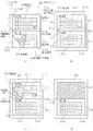
図15は、本発明のラベルの第4の実施の形態を示す図であり、(a)は正面図、(b)は(a)に示したA−A’断面図、(c)は(a)に示したB−B’断面図、(d)は上基材310の裏面の構成を示す図、(e)は下基材320の表面の構成を示す図である。
(Fourth embodiment)
FIGS. 15A and 15B are views showing a fourth embodiment of the label of the present invention, in which FIG. 15A is a front view, FIG. 15B is a cross-sectional view taken along the line AA ′ shown in FIG. BB 'sectional drawing shown to a), (d) is a figure which shows the structure of the back surface of the upper base material 310, (e) is a figure which shows the structure of the surface of the lower base material 320. FIG.

本形態は図15に示すように、第3の実施の形態に示したものに対して、ジッパー部218の代わりに2つのマイクロミシン318が設けられている点のみが異なるものである。   As shown in FIG. 15, this embodiment is different from that shown in the third embodiment only in that two micro sewing machines 318 are provided instead of the zipper portion 218.

図16は、図15に示した剥離開始端部311cの詳細な構成を示す図である。   FIG. 16 is a diagram showing a detailed configuration of the peeling start end portion 311c shown in FIG.

図16に示すように、下基材320の表面においては、剥離開始端部311cに対向する領域が、非貼着部であるのり抜き部315(図中「×」で示す)となっている。また、その一部に、スリット313aの代わりにジッパー部314が設けられるとともに、スリット313bの代わりにマイクロミシン318が設けられている。   As shown in FIG. 16, in the surface of the lower base material 320, the area | region which opposes the peeling start end part 311c becomes the paste part 315 (it shows with "x" in a figure) which is a non-sticking part. . In addition, a zipper portion 314 is provided in place of the slit 313a, and a micro sewing machine 318 is provided in place of the slit 313b.

ジッパー部314は、配達票311と貼付票312とがスリット213aを介さずに連接したタイ部314bと、タイ部314bの剥離開始端部311cを含む角部とは反対側に隣接するスリット313aの端部から連続し、配達票311の内部に鈍角を有して斜めに延びた斜め切り込み部314aとから構成されている。   The zipper portion 314 includes a tie portion 314b in which the delivery slip 311 and the sticker slip 312 are connected without the slit 213a, and a slit 313a adjacent to the opposite side of the corner portion including the peeling start end portion 311c of the tie portion 314b. Continuing from the end portion, the delivery slip 311 has an oblique cut portion 314a having an obtuse angle and extending obliquely.

マイクロミシン318は、細かな孔が微細な間隔で直線上に並んで構成されている。   The micro-sewing machine 318 is configured such that fine holes are arranged on a straight line at fine intervals.

のり抜き部315は、第1の実施の形態にて示したものと同様に、配達票311の角部のうち剥離開始端部311cを含む角部を頂点とした二等辺三角形の形状を有している。   The glued portion 315 has the shape of an isosceles triangle whose apex is the corner including the peeling start end 311c among the corners of the delivery slip 311 as in the first embodiment. ing.

このように、のり抜き部315において、スリット313aの代わりにジッパー部314が設けられるとともに、スリット313bの代わりにマイクロミシン318が設けられることにより、スリット313a,313bがのり抜き部315にて部分的に途切れた構成となっている。   As described above, in the scraped portion 315, the zipper portion 314 is provided instead of the slit 313a, and the micro sewing machine 318 is provided instead of the slit 313b, so that the slits 313a and 313b are partially formed in the scraped portion 315. It has become a discontinuous configuration.

以下に、上記のように構成された配送ラベルシート300の作用について説明する。   The operation of the delivery label sheet 300 configured as described above will be described below.

図17は、図15に示した配送ラベルシート300の作用を説明するための図であり、のり抜き部315近傍の断面を示す。なお、図17においては、剥離紙330の構成及び粘着剤342の図示は省略している。   FIG. 17 is a view for explaining the operation of the delivery label sheet 300 shown in FIG. 15 and shows a cross section near the scraped portion 315. In FIG. 17, the configuration of the release paper 330 and the adhesive 342 are not shown.

図15に示した配送ラベルシート300においては、第1の実施の形態にて示したものと同様に、配送ラベル301のそれぞれについて、配達票311及び貼付票312のそれぞれに設けられた配送情報印字領域311a,312aに、その配送ラベル301が貼着されて配送される配送物の配送元及び配送先の住所や氏名あるいは名称等の配送情報311d,312dが印字される際、プリンタ内を搬送されることになる。なお、図15に示した配送ラベルシート300は、プリンタ内において、スタブ317側が先端となって搬送されるものとする。   In the delivery label sheet 300 shown in FIG. 15, the delivery information printing provided on each of the delivery slip 311 and the sticker slip 312 for each of the delivery labels 301 is the same as that shown in the first embodiment. When the delivery information 311d, 312d such as the address, name, or name of the delivery source and delivery destination of the delivery to be delivered with the delivery label 301 attached is printed in the areas 311a, 312a, it is conveyed through the printer. Will be. It is assumed that the delivery label sheet 300 shown in FIG. 15 is conveyed with the stub 317 side as the leading end in the printer.

ここで、配達票311のうち剥離開始端部311cは、のり抜き部315となっていることから下基材320に貼着されていないため、プリンタ内を搬送された場合、スタブ317との連接部分において、配達票311がスリット313bから捲れ上がってしまう虞れがある。ところが、図15に示した配送ラベルシート300は、上述したように、のり抜き部315の一部に、スリット313bの代わりに2つのマイクロミシン318が設けられており、マイクロミシン318の2つの孔間において、配達票311がスタブ317に繋がった状態となっているため、のり抜き部315においても、配達票311の剥離開始端部311cが、スタブ217によって固定されていることになる。それにより、図17(a)に示すように、例えば、プリンタ内にて湾曲しながら搬送された場合であっても、スタブ317との連接部分において、配達票311がスリット313bから捲れ上がることがなくなり、プリンタ内にて上基材310と下基材320とが剥離してしまうことが回避されることになる。   Here, the peeling start end portion 311c of the delivery slip 311 is not affixed to the lower base material 320 because it is a paste-out portion 315, and therefore, when transported through the printer, it is connected to the stub 317. In the portion, there is a possibility that the delivery slip 311 is rolled up from the slit 313b. However, as described above, the delivery label sheet 300 shown in FIG. 15 is provided with two micro-sewing machines 318 instead of the slits 313b in a part of the glued portion 315, and the two holes of the micro-sewing machine 318 are provided. In the meantime, since the delivery slip 311 is connected to the stub 317, the peeling start end portion 311 c of the delivery slip 311 is fixed by the stub 217 also in the scraped portion 315. As a result, as shown in FIG. 17A, for example, even when the sheet is conveyed while being curved in the printer, the delivery slip 311 can be rolled up from the slit 313b at the connection portion with the stub 317. Thus, the upper substrate 310 and the lower substrate 320 are prevented from being peeled off in the printer.

また、2つの配送ラベル301の配達票311が連接した部分においても同様に、配達票311がスリット313bから捲れ上がってしまう虞れがある。ところが、図15に示した配送ラベルシート300は、上述したように、のり抜き部315の一部に、スリット313bの代わりに2つのマイクロミシン318が設けられており、マイクロミシン318の2つの孔間において、配達票311が、それに連接する配達票311に繋がった状態となっているため、のり抜き部315においても、配達票311の剥離開始端部311cが、それに連接する配達票311の下基材320に貼着されている部分に固定されていることになる。それにより、図17(b)に示すように、例えば、プリンタ内にて湾曲しながら搬送された場合であっても、2つの配送ラベル301の配達票311が連接した部分において、配達票311がスリット313bから捲れ上がることがなくなり、プリンタ内にて上基材310と下基材320とが剥離してしまうことが回避されることになる。   Similarly, in the portion where the delivery slips 311 of the two delivery labels 301 are connected, there is a possibility that the delivery slips 311 may be rolled up from the slits 313b. However, as described above, the delivery label sheet 300 shown in FIG. 15 is provided with two micro-sewing machines 318 instead of the slits 313b in a part of the glued portion 315, and the two holes of the micro-sewing machine 318 are provided. In the meantime, since the delivery slip 311 is connected to the delivery slip 311 connected to the delivery slip 311, the peeling start end portion 311 c of the delivery slip 311 is also below the delivery slip 311 connected to the scraped portion 315. That is, it is fixed to the portion stuck to the base material 320. As a result, as shown in FIG. 17B, for example, even when the sheet is conveyed while curving in the printer, the delivery slip 311 is formed at the portion where the delivery slips 311 of the two delivery labels 301 are connected. As a result, the upper base material 310 and the lower base material 320 are prevented from peeling off in the printer.

また、上記のような作用は、配送ラベルシート300の搬送方向に直交する方向についても生じる場合があり、その場合は、第3の実施の形態にて示したものと同様に、ジッパー部314によって、配達票311がスリット313aから捲れ上がることが回避されることになる。   In addition, the above-described action may also occur in a direction orthogonal to the conveyance direction of the delivery label sheet 300. In this case, the zipper portion 314 is used in the same manner as that described in the third embodiment. Thus, it is avoided that the delivery slip 311 is rolled up from the slit 313a.

以下に、上記のように構成された配送ラベルシート300の使用方法について説明する。   Below, the usage method of the delivery label sheet 300 comprised as mentioned above is demonstrated.

図18は、図15に示した配送ラベルシート300の使用方法を説明するための図である。   FIG. 18 is a view for explaining a method of using the delivery label sheet 300 shown in FIG.

図15に示した配送ラベルシート300は、まず、図18(a)に示すように、配送ラベル301のそれぞれについて、配達票311及び貼付票312のそれぞれに設けられた配送情報印字領域311a,312aに、配送ラベル301が貼着されて配送される配送物の配送元及び配送先の住所や氏名あるいは名称等の配送情報311d,312dが印字された後、配送ラベル301毎に、下基材320が剥離紙330から剥離されて配送ラベルシート300から分離される。またそれにより、配送ラベル301はスタブ317から分離される。なお、配送ラベル301に配送情報311d,312dが印字される際、上述したように、マイクロミシン318によって上基材310の下基材320からの不用意な剥離が回避される。   First, as shown in FIG. 18A, the delivery label sheet 300 shown in FIG. 15 includes delivery information print areas 311a and 312a provided on the delivery slip 311 and the sticker slip 312 for each delivery label 301. In addition, after the delivery information 311d and 312d such as the address, name, and name of the delivery item to be delivered with the delivery label 301 attached is delivered, the lower base material 320 is provided for each delivery label 301. Is peeled from the release paper 330 and separated from the delivery label sheet 300. Thereby, the delivery label 301 is separated from the stub 317. In addition, when the delivery information 311d and 312d are printed on the delivery label 301, as described above, the microsewing machine 318 prevents inadvertent peeling from the lower base material 320 of the upper base material 310.

下基材320が剥離紙330から剥離されて配送ラベルシート300から分離した配送ラベル301は、下基材320の裏面に塗工された粘着剤342が表出し、図18(b)に示すように、この粘着剤342によって配送物302に貼着される。   As shown in FIG. 18B, the delivery label 301 separated from the delivery label sheet 300 after the lower substrate 320 is peeled off from the release paper 330 is exposed to the adhesive 342 applied to the back surface of the lower substrate 320. The adhesive 342 is attached to the delivery item 302.

配送ラベル301が貼着された配送物302が、配送情報印字領域311a,312aに印字された配送情報311d,312dに従って配送先に届けられると、配達票311の押印領域311bに受領印が押下され、図18(c),(d)に示すように、第3の実施の形態にて示したものと同様に、配達票311が、剥離開始端部311cを剥離開始端として下基材320から剥離され、配送ラベル301から分離される。   When the delivery item 302 to which the delivery label 301 is attached is delivered to the delivery destination in accordance with the delivery information 311d and 312d printed in the delivery information print areas 311a and 312a, the receipt stamp is pressed in the seal area 311b of the delivery slip 311. As shown in FIGS. 18C and 18D, similarly to the one shown in the third embodiment, the delivery slip 311 is separated from the lower base material 320 with the peeling start end 311c as the peeling start end. It is peeled off and separated from the delivery label 301.

配送ラベル301から分離した配達票311は、配送業者等にて持ち帰られることになる。   The delivery slip 311 separated from the delivery label 301 is taken home by a delivery company or the like.

このように、本形態においては、配達票311の下基材320からの剥離を開始する剥離開始端部311cがのり抜き部315となって下基材320に貼着されておらず、剥離開始端部311cの一部に、配達票311どうし及び下基材320の配達票311に対向する領域どうし、または配達票311及び下基材320の配達票311に対向する領域とスタブ317とが連接しているスリット313bの代わりに、マイクロミシン318を設けたことにより、配達票311を下基材320から剥離しやすくしながらも、プリンタにて搬送する際等において、上基材310と下基材320とが不用意に剥離してしまうことを回避することができる。また、配達票311と貼付票312とが連接しているスリット313aの代わりに、ジッパー部314を設けたことによっても、同様の効果を奏する。   Thus, in this embodiment, the peeling start end 311c that starts peeling from the lower base material 320 of the delivery slip 311 is not affixed to the lower base material 320 as a scraped portion 315, and peeling starts. The stub 317 is connected to a part of the end portion 311c between the delivery slips 311 and the regions facing the delivery slips 311 of the lower base material 320 or between the delivery slips 311 and the lower base material 320 facing the delivery slips 311. By providing the micro-sewing machine 318 instead of the slit 313b, the delivery sheet 311 can be easily separated from the lower base material 320, but the upper base material 310 and the lower base material can be easily transported by a printer. It can be avoided that the material 320 is inadvertently peeled off. Further, the same effect can be obtained by providing a zipper portion 314 instead of the slit 313a where the delivery slip 311 and the sticking slip 312 are connected.

なお、スリットが部分的に途切れた構成としては、上述したようなジッパー部やマイクロミシンではなく、単純なタイのみでもよい。また、ジッパー部やマイクロミシンの数は、上述した実施の形態にて示したものに限らないが、配送ラベルや配達票の分離しやすさを考慮すると、剥離開始端部の辺の長さに対して、タイを合計した長さの比率が、1〜3割程度であることが望ましい。   In addition, as a structure in which the slit is partially interrupted, only a simple tie may be used instead of the zipper part or the micro sewing machine as described above. Further, the number of zipper parts and micro-sewing machines is not limited to those shown in the above-described embodiment, but considering the ease of separation of delivery labels and delivery slips, the number of sides of the peeling start end part is On the other hand, it is desirable that the ratio of the total length of the ties is about 10 to 30%.

また、上述した実施の形態においては、上基材の裏面に塗工された剥離剤と下基材の表面に塗工された粘着剤とによって配達票が下基材に剥離可能に貼着されているが、感圧接着剤等、貼着後の剥離が可能となる接着剤を用いて、配達票を下基材に剥離可能に貼着した構成としてもよい。   In the above-described embodiment, the delivery slip is detachably attached to the lower substrate by the release agent applied to the back surface of the upper substrate and the adhesive applied to the surface of the lower substrate. However, it is good also as a structure which stuck the delivery slip on the lower base material using the adhesive which can peel after sticking, such as a pressure sensitive adhesive.

1,101,201,301 配送ラベル
2,102,202,302 配送物
10,110,210,310 上基材
11,111,211,311 配達票
11a,12a,111a,112a,211a,212a,311a,312a 配送情報印字領域
11b,111b,211b,311b 押印領域
11c,111c,211c,311c 剥離開始端部
11d,12d,111d,112d,211d,212d,311d,312d 配送情報
12,112,212,312 貼付票
13,113,213a,213b,313a,313b スリット
14,214,218,314 ジッパー部
14a,214a,218a,314a 斜め切り込み部
14b,214b,218b,314b タイ部
15,115,215,315 のり抜き部
16,216 破断部分
20,120,220,320 下基材
30,130,230,330 剥離紙
31,131,231,331 剥離台紙
32,50,132,150,232,250,332,350 剥離剤
41,42,141,142,241,242,341,342 粘着剤
114,318 マイクロミシン
200,300 配送ラベルシート
1, 101, 201, 301 Delivery label 2, 102, 202, 302 Delivery item 10, 110, 210, 310 Upper substrate 11, 111, 211, 311 Delivery slip 11a, 12a, 111a, 112a, 211a, 212a, 311a , 312a Delivery information printing area 11b, 111b, 211b, 311b Sealing area 11c, 111c, 211c, 311c Separation start end 11d, 12d, 111d, 112d, 211d, 212d, 311d, 312d Delivery information 12, 112, 212, 312 Attached slip 13, 113, 213a, 213b, 313a, 313b Slit 14, 214, 218, 314 Zipper part 14a, 214a, 218a, 314a Diagonal cut part 14b, 214b, 218b, 314b Tie part 15, 115, 215, 3 5 Extruded portion 16,216 Broken portion 20,120,220,320 Lower substrate 30,130,230,330 Release paper 31,131,231,331 Release mount 32,50,132,150,232,250,332 , 350 Release agent 41, 42, 141, 142, 241, 242, 341, 342 Adhesive 114, 318 Micro sewing machine 200, 300 Delivery label sheet

Claims (1)

第1の領域と第2の領域とが、連続した第1の切り離し線を介して連接した第1のシートと、
前記第1のシートの一方の面に貼着され、前記第1のシートとの貼着面とは反対側の面に粘着層を具備する第2のシートと、
前記粘着層によって第2のシートに剥離可能に貼着された第3のシートとを有し、
前記第1のシートが、前記第1の領域が前記第2のシートから剥離可能に構成されるとともに、前記第1の領域のうち、前記第1の切り離し線に沿う領域にて当該第1の領域の1つの角部を含むように設けられ、該第1の領域の前記第2のシートからの剥離を開始する剥離開始端部が、前記第2のシートに貼着されていない非貼着部となっており、前記第2のシートから前記第3のシートが剥離されて前記粘着層によって被着体に貼着されて使用されるラベルにおいて、
前記第1、第2及び第3のシートは、前記第1の領域と前記第2の領域との連接方向に直交する方向に、前記剥離開始端部を含む辺から延設した延設部を有し、
前記第1及び第2のシートは、前記剥離開始端部を含む辺に、連続した第2の切り離し線を有し、
前記第1の切り離し線が、前記非貼着部においてタイ部とスリット部と斜め切り込み部とからなり、
前記斜め切り込み部は、前記タイ部の前記剥離開始端部とは反対側に隣接するスリット部の端部から連続し、該スリット部に対して前記第1の領域の内部に鈍角を有して斜めに延び、
前記第1のシートにおいて、前記第2の切り離し線が前記非貼着部にてマイクロミシンから構成されていることを特徴とするラベル。
A first sheet in which the first region and the second region are connected via a continuous first separation line;
A second sheet that is adhered to one surface of the first sheet, and includes an adhesive layer on the surface opposite to the adhesion surface to the first sheet;
Having a third sheet releasably attached to the second sheet by the adhesive layer;
The first sheet is configured such that the first region can be peeled from the second sheet, and the first sheet is formed in a region along the first separation line in the first region. Non-sticking that is provided so as to include one corner of a region, and a peeling start end portion that starts peeling of the first region from the second sheet is not stuck to the second sheet In the label used by being attached to an adherend by the adhesive layer by peeling the third sheet from the second sheet,
The first sheet, the second sheet, and the third sheet include an extending portion that extends from a side including the peeling start end portion in a direction orthogonal to a connecting direction between the first region and the second region. Have
The first and second sheets have a continuous second separation line on a side including the peeling start end,
The first separation line consists of a tie portion, a slit portion, and an oblique cut portion in the non-sticking portion,
The oblique cut portion is continuous from an end portion of the slit portion adjacent to the side opposite to the peeling start end portion of the tie portion, and has an obtuse angle inside the first region with respect to the slit portion. Extending diagonally,
The said 1st sheet | seat WHEREIN: The said 2nd separating line is comprised from the microsewing machine in the said non-sticking part, The label characterized by the above-mentioned .
JP2013226141A 2013-10-31 2013-10-31 label Active JP6328907B2 (en)

Priority Applications (1)

Application Number Priority Date Filing Date Title
JP2013226141A JP6328907B2 (en) 2013-10-31 2013-10-31 label

Applications Claiming Priority (1)

Application Number Priority Date Filing Date Title
JP2013226141A JP6328907B2 (en) 2013-10-31 2013-10-31 label

Publications (3)

Publication Number Publication Date
JP2015087559A JP2015087559A (en) 2015-05-07
JP2015087559A5 JP2015087559A5 (en) 2016-12-15
JP6328907B2 true JP6328907B2 (en) 2018-05-23

Family

ID=53050413

Family Applications (1)

Application Number Title Priority Date Filing Date
JP2013226141A Active JP6328907B2 (en) 2013-10-31 2013-10-31 label

Country Status (1)

Country Link
JP (1) JP6328907B2 (en)

Family Cites Families (5)

* Cited by examiner, † Cited by third party
Publication number Priority date Publication date Assignee Title
JP4139503B2 (en) * 1999-02-01 2008-08-27 大日本印刷株式会社 Delivery slip and sheet with it
US6254952B1 (en) * 1999-02-26 2001-07-03 Ncr Corporation Strip tied label sheet
JP2001353987A (en) * 2000-06-13 2001-12-25 Dainippon Printing Co Ltd Delivery slip
JP2007290278A (en) * 2006-04-26 2007-11-08 Toppan Forms Co Ltd Separating sheet
JP5699330B2 (en) * 2011-03-18 2015-04-08 大日本印刷株式会社 Delivery slip

Also Published As

Publication number Publication date
JP2015087559A (en) 2015-05-07

Similar Documents

Publication Publication Date Title
JP2006281739A (en) Label slip
JP4845192B2 (en) Separation sheet
JP2010264611A (en) Delivery slip
JPWO2017150386A1 (en) Peelable laminate
JP3672355B2 (en) Delivery slip
JP6209057B2 (en) label
WO2014122795A1 (en) Label
JP5602359B2 (en) Delivery label slip
JP6328907B2 (en) label
JP2016153857A (en) Label sheet
JP4695764B2 (en) Adhesive sheet with separable display
JP6647163B2 (en) Delivery slip
JP5705081B2 (en) Delivery slip
JP5592149B2 (en) Separation sheet
JP6276512B2 (en) Bag-like label
JP2008039837A (en) Label
JP2007290278A (en) Separating sheet
JP6618406B2 (en) Sheet body
JP2003136861A (en) Delivery slip and manufacturing method therefor
JP6395367B2 (en) Shipping label
JP3595021B2 (en) Delivery slip for printing
JP6391267B2 (en) label
JP6568728B2 (en) Pseudo adhesive sheet
JP6929663B2 (en) label
JP2005125599A (en) Label slip

Legal Events

Date Code Title Description
A521 Request for written amendment filed

Free format text: JAPANESE INTERMEDIATE CODE: A523

Effective date: 20161025

A621 Written request for application examination

Free format text: JAPANESE INTERMEDIATE CODE: A621

Effective date: 20161025

A131 Notification of reasons for refusal

Free format text: JAPANESE INTERMEDIATE CODE: A131

Effective date: 20170912

A977 Report on retrieval

Free format text: JAPANESE INTERMEDIATE CODE: A971007

Effective date: 20170915

A521 Request for written amendment filed

Free format text: JAPANESE INTERMEDIATE CODE: A523

Effective date: 20171101

TRDD Decision of grant or rejection written
A01 Written decision to grant a patent or to grant a registration (utility model)

Free format text: JAPANESE INTERMEDIATE CODE: A01

Effective date: 20180417

A61 First payment of annual fees (during grant procedure)

Free format text: JAPANESE INTERMEDIATE CODE: A61

Effective date: 20180419

R150 Certificate of patent or registration of utility model

Ref document number: 6328907

Country of ref document: JP

Free format text: JAPANESE INTERMEDIATE CODE: R150

R250 Receipt of annual fees

Free format text: JAPANESE INTERMEDIATE CODE: R250

R250 Receipt of annual fees

Free format text: JAPANESE INTERMEDIATE CODE: R250

R250 Receipt of annual fees

Free format text: JAPANESE INTERMEDIATE CODE: R250

S533 Written request for registration of change of name

Free format text: JAPANESE INTERMEDIATE CODE: R313533

R350 Written notification of registration of transfer

Free format text: JAPANESE INTERMEDIATE CODE: R350

S111 Request for change of ownership or part of ownership

Free format text: JAPANESE INTERMEDIATE CODE: R313113

R350 Written notification of registration of transfer

Free format text: JAPANESE INTERMEDIATE CODE: R350

R250 Receipt of annual fees

Free format text: JAPANESE INTERMEDIATE CODE: R250