JP6325543B2 - Instruments and systems for thrombus treatment - Google Patents
Instruments and systems for thrombus treatment Download PDFInfo
- Publication number
- JP6325543B2 JP6325543B2 JP2015527481A JP2015527481A JP6325543B2 JP 6325543 B2 JP6325543 B2 JP 6325543B2 JP 2015527481 A JP2015527481 A JP 2015527481A JP 2015527481 A JP2015527481 A JP 2015527481A JP 6325543 B2 JP6325543 B2 JP 6325543B2
- Authority
- JP
- Japan
- Prior art keywords
- body frame
- tethers
- thrombus
- instrument
- tether
- Prior art date
- Legal status (The legal status is an assumption and is not a legal conclusion. Google has not performed a legal analysis and makes no representation as to the accuracy of the status listed.)
- Active
Links
- 208000007536 Thrombosis Diseases 0.000 title claims description 402
- 238000011282 treatment Methods 0.000 title claims description 98
- 230000033001 locomotion Effects 0.000 claims description 173
- 238000013151 thrombectomy Methods 0.000 claims description 136
- 239000000463 material Substances 0.000 claims description 59
- 230000001732 thrombotic effect Effects 0.000 claims description 59
- 230000007935 neutral effect Effects 0.000 claims description 32
- 230000000087 stabilizing effect Effects 0.000 claims description 25
- 239000000126 substance Substances 0.000 claims description 19
- 230000004044 response Effects 0.000 claims description 3
- 238000000034 method Methods 0.000 description 83
- 210000004204 blood vessel Anatomy 0.000 description 44
- 230000017531 blood circulation Effects 0.000 description 42
- 238000010494 dissociation reaction Methods 0.000 description 39
- 230000005593 dissociations Effects 0.000 description 39
- 210000004369 blood Anatomy 0.000 description 26
- 239000008280 blood Substances 0.000 description 26
- 239000003527 fibrinolytic agent Substances 0.000 description 25
- 210000005166 vasculature Anatomy 0.000 description 18
- 229960000103 thrombolytic agent Drugs 0.000 description 15
- 230000002537 thrombolytic effect Effects 0.000 description 15
- 239000012634 fragment Substances 0.000 description 14
- 230000001965 increasing effect Effects 0.000 description 13
- 230000002885 thrombogenetic effect Effects 0.000 description 11
- 210000004027 cell Anatomy 0.000 description 10
- 238000001914 filtration Methods 0.000 description 10
- 230000008569 process Effects 0.000 description 10
- 238000010586 diagram Methods 0.000 description 9
- 230000036961 partial effect Effects 0.000 description 9
- 229910001000 nickel titanium Inorganic materials 0.000 description 7
- HLXZNVUGXRDIFK-UHFFFAOYSA-N nickel titanium Chemical compound [Ti].[Ti].[Ti].[Ti].[Ti].[Ti].[Ti].[Ti].[Ti].[Ti].[Ti].[Ni].[Ni].[Ni].[Ni].[Ni].[Ni].[Ni].[Ni].[Ni].[Ni].[Ni].[Ni].[Ni].[Ni] HLXZNVUGXRDIFK-UHFFFAOYSA-N 0.000 description 7
- 239000002245 particle Substances 0.000 description 7
- 230000002093 peripheral effect Effects 0.000 description 7
- 230000002526 effect on cardiovascular system Effects 0.000 description 6
- 229920001343 polytetrafluoroethylene Polymers 0.000 description 6
- 239000004810 polytetrafluoroethylene Substances 0.000 description 6
- 239000011148 porous material Substances 0.000 description 6
- 239000007787 solid Substances 0.000 description 6
- 238000012800 visualization Methods 0.000 description 6
- 230000000875 corresponding effect Effects 0.000 description 5
- 208000014674 injury Diseases 0.000 description 5
- 230000002101 lytic effect Effects 0.000 description 5
- 230000006641 stabilisation Effects 0.000 description 5
- 238000011105 stabilization Methods 0.000 description 5
- 230000008733 trauma Effects 0.000 description 5
- 230000002792 vascular Effects 0.000 description 5
- 230000009471 action Effects 0.000 description 4
- 239000002872 contrast media Substances 0.000 description 4
- 239000010432 diamond Substances 0.000 description 4
- 239000006260 foam Substances 0.000 description 4
- 239000007789 gas Substances 0.000 description 4
- 239000000499 gel Substances 0.000 description 4
- 239000008187 granular material Substances 0.000 description 4
- 239000007788 liquid Substances 0.000 description 4
- 230000010412 perfusion Effects 0.000 description 4
- 230000002829 reductive effect Effects 0.000 description 4
- 206010051055 Deep vein thrombosis Diseases 0.000 description 3
- 102000003978 Tissue Plasminogen Activator Human genes 0.000 description 3
- 108090000373 Tissue Plasminogen Activator Proteins 0.000 description 3
- RTAQQCXQSZGOHL-UHFFFAOYSA-N Titanium Chemical compound [Ti] RTAQQCXQSZGOHL-UHFFFAOYSA-N 0.000 description 3
- 206010047249 Venous thrombosis Diseases 0.000 description 3
- 230000000712 assembly Effects 0.000 description 3
- 238000000429 assembly Methods 0.000 description 3
- 230000008901 benefit Effects 0.000 description 3
- 229910003460 diamond Inorganic materials 0.000 description 3
- 238000004090 dissolution Methods 0.000 description 3
- 229940079593 drug Drugs 0.000 description 3
- 239000003814 drug Substances 0.000 description 3
- 230000000694 effects Effects 0.000 description 3
- 229920000295 expanded polytetrafluoroethylene Polymers 0.000 description 3
- 238000003780 insertion Methods 0.000 description 3
- 230000037431 insertion Effects 0.000 description 3
- 239000002184 metal Substances 0.000 description 3
- 229910052751 metal Inorganic materials 0.000 description 3
- 230000000144 pharmacologic effect Effects 0.000 description 3
- 229920000642 polymer Polymers 0.000 description 3
- -1 polytetrafluoroethylene Polymers 0.000 description 3
- 229910001220 stainless steel Inorganic materials 0.000 description 3
- 239000010935 stainless steel Substances 0.000 description 3
- 230000009424 thromboembolic effect Effects 0.000 description 3
- 229960000187 tissue plasminogen activator Drugs 0.000 description 3
- 239000010936 titanium Substances 0.000 description 3
- 238000012546 transfer Methods 0.000 description 3
- 208000005189 Embolism Diseases 0.000 description 2
- HTTJABKRGRZYRN-UHFFFAOYSA-N Heparin Chemical compound OC1C(NC(=O)C)C(O)OC(COS(O)(=O)=O)C1OC1C(OS(O)(=O)=O)C(O)C(OC2C(C(OS(O)(=O)=O)C(OC3C(C(O)C(O)C(O3)C(O)=O)OS(O)(=O)=O)C(CO)O2)NS(O)(=O)=O)C(C(O)=O)O1 HTTJABKRGRZYRN-UHFFFAOYSA-N 0.000 description 2
- 238000011360 adjunctive therapy Methods 0.000 description 2
- 210000001367 artery Anatomy 0.000 description 2
- 230000004888 barrier function Effects 0.000 description 2
- 239000000560 biocompatible material Substances 0.000 description 2
- 210000004556 brain Anatomy 0.000 description 2
- 230000015556 catabolic process Effects 0.000 description 2
- 230000035602 clotting Effects 0.000 description 2
- 239000011248 coating agent Substances 0.000 description 2
- 238000000576 coating method Methods 0.000 description 2
- 230000008878 coupling Effects 0.000 description 2
- 238000010168 coupling process Methods 0.000 description 2
- 238000005859 coupling reaction Methods 0.000 description 2
- 230000009089 cytolysis Effects 0.000 description 2
- 238000006731 degradation reaction Methods 0.000 description 2
- 238000006073 displacement reaction Methods 0.000 description 2
- 230000001747 exhibiting effect Effects 0.000 description 2
- 239000000835 fiber Substances 0.000 description 2
- 229960002897 heparin Drugs 0.000 description 2
- 229920000669 heparin Polymers 0.000 description 2
- 239000012528 membrane Substances 0.000 description 2
- 208000010125 myocardial infarction Diseases 0.000 description 2
- 210000000056 organ Anatomy 0.000 description 2
- 230000008520 organization Effects 0.000 description 2
- 230000035515 penetration Effects 0.000 description 2
- 238000012545 processing Methods 0.000 description 2
- 238000000926 separation method Methods 0.000 description 2
- 238000001356 surgical procedure Methods 0.000 description 2
- 229910052719 titanium Inorganic materials 0.000 description 2
- 230000007704 transition Effects 0.000 description 2
- 229910001200 Ferrotitanium Inorganic materials 0.000 description 1
- 108010010803 Gelatin Proteins 0.000 description 1
- 208000032382 Ischaemic stroke Diseases 0.000 description 1
- 208000028389 Nerve injury Diseases 0.000 description 1
- 239000004677 Nylon Substances 0.000 description 1
- 239000004372 Polyvinyl alcohol Substances 0.000 description 1
- 208000010378 Pulmonary Embolism Diseases 0.000 description 1
- 208000006011 Stroke Diseases 0.000 description 1
- 208000001435 Thromboembolism Diseases 0.000 description 1
- 208000027418 Wounds and injury Diseases 0.000 description 1
- 230000001154 acute effect Effects 0.000 description 1
- 238000011374 additional therapy Methods 0.000 description 1
- 210000003484 anatomy Anatomy 0.000 description 1
- 239000003146 anticoagulant agent Substances 0.000 description 1
- 229940127219 anticoagulant drug Drugs 0.000 description 1
- QVGXLLKOCUKJST-UHFFFAOYSA-N atomic oxygen Chemical compound [O] QVGXLLKOCUKJST-UHFFFAOYSA-N 0.000 description 1
- 230000002457 bidirectional effect Effects 0.000 description 1
- 230000015572 biosynthetic process Effects 0.000 description 1
- 230000036770 blood supply Effects 0.000 description 1
- 210000004958 brain cell Anatomy 0.000 description 1
- 239000003795 chemical substances by application Substances 0.000 description 1
- 230000000295 complement effect Effects 0.000 description 1
- 239000002131 composite material Substances 0.000 description 1
- 230000006835 compression Effects 0.000 description 1
- 238000007906 compression Methods 0.000 description 1
- 230000002596 correlated effect Effects 0.000 description 1
- 238000013461 design Methods 0.000 description 1
- 238000012377 drug delivery Methods 0.000 description 1
- 230000003073 embolic effect Effects 0.000 description 1
- 230000002708 enhancing effect Effects 0.000 description 1
- 238000011049 filling Methods 0.000 description 1
- 230000006870 function Effects 0.000 description 1
- 239000008273 gelatin Substances 0.000 description 1
- 229920000159 gelatin Polymers 0.000 description 1
- 235000019322 gelatine Nutrition 0.000 description 1
- 235000011852 gelatine desserts Nutrition 0.000 description 1
- 238000011065 in-situ storage Methods 0.000 description 1
- 230000001939 inductive effect Effects 0.000 description 1
- 230000002401 inhibitory effect Effects 0.000 description 1
- 230000003993 interaction Effects 0.000 description 1
- 230000009545 invasion Effects 0.000 description 1
- 230000000302 ischemic effect Effects 0.000 description 1
- 238000009940 knitting Methods 0.000 description 1
- 210000004072 lung Anatomy 0.000 description 1
- 238000002803 maceration Methods 0.000 description 1
- 238000002483 medication Methods 0.000 description 1
- 239000007769 metal material Substances 0.000 description 1
- 150000002739 metals Chemical class 0.000 description 1
- 230000005012 migration Effects 0.000 description 1
- 238000013508 migration Methods 0.000 description 1
- 230000008764 nerve damage Effects 0.000 description 1
- 230000001537 neural effect Effects 0.000 description 1
- 229920001778 nylon Polymers 0.000 description 1
- 239000001301 oxygen Substances 0.000 description 1
- 229910052760 oxygen Inorganic materials 0.000 description 1
- 210000005259 peripheral blood Anatomy 0.000 description 1
- 239000011886 peripheral blood Substances 0.000 description 1
- 229920000728 polyester Polymers 0.000 description 1
- 229920002451 polyvinyl alcohol Polymers 0.000 description 1
- 239000000843 powder Substances 0.000 description 1
- 238000002360 preparation method Methods 0.000 description 1
- 230000001737 promoting effect Effects 0.000 description 1
- 230000001681 protective effect Effects 0.000 description 1
- 238000002601 radiography Methods 0.000 description 1
- 230000009467 reduction Effects 0.000 description 1
- 230000000717 retained effect Effects 0.000 description 1
- 230000001225 therapeutic effect Effects 0.000 description 1
- 210000003462 vein Anatomy 0.000 description 1
Images


Classifications
-
- A—HUMAN NECESSITIES
- A61—MEDICAL OR VETERINARY SCIENCE; HYGIENE
- A61B—DIAGNOSIS; SURGERY; IDENTIFICATION
- A61B17/00—Surgical instruments, devices or methods, e.g. tourniquets
- A61B17/22—Implements for squeezing-off ulcers or the like on the inside of inner organs of the body; Implements for scraping-out cavities of body organs, e.g. bones; Calculus removers; Calculus smashing apparatus; Apparatus for removing obstructions in blood vessels, not otherwise provided for
- A61B17/221—Gripping devices in the form of loops or baskets for gripping calculi or similar types of obstructions
-
- A—HUMAN NECESSITIES
- A61—MEDICAL OR VETERINARY SCIENCE; HYGIENE
- A61B—DIAGNOSIS; SURGERY; IDENTIFICATION
- A61B17/00—Surgical instruments, devices or methods, e.g. tourniquets
- A61B17/32—Surgical cutting instruments
- A61B17/3205—Excision instruments
- A61B17/3207—Atherectomy devices working by cutting or abrading; Similar devices specially adapted for non-vascular obstructions
- A61B17/320725—Atherectomy devices working by cutting or abrading; Similar devices specially adapted for non-vascular obstructions with radially expandable cutting or abrading elements
-
- A—HUMAN NECESSITIES
- A61—MEDICAL OR VETERINARY SCIENCE; HYGIENE
- A61B—DIAGNOSIS; SURGERY; IDENTIFICATION
- A61B17/00—Surgical instruments, devices or methods, e.g. tourniquets
- A61B17/32—Surgical cutting instruments
- A61B17/3205—Excision instruments
- A61B17/3207—Atherectomy devices working by cutting or abrading; Similar devices specially adapted for non-vascular obstructions
- A61B17/320758—Atherectomy devices working by cutting or abrading; Similar devices specially adapted for non-vascular obstructions with a rotating cutting instrument, e.g. motor driven
-
- A—HUMAN NECESSITIES
- A61—MEDICAL OR VETERINARY SCIENCE; HYGIENE
- A61F—FILTERS IMPLANTABLE INTO BLOOD VESSELS; PROSTHESES; DEVICES PROVIDING PATENCY TO, OR PREVENTING COLLAPSING OF, TUBULAR STRUCTURES OF THE BODY, e.g. STENTS; ORTHOPAEDIC, NURSING OR CONTRACEPTIVE DEVICES; FOMENTATION; TREATMENT OR PROTECTION OF EYES OR EARS; BANDAGES, DRESSINGS OR ABSORBENT PADS; FIRST-AID KITS
- A61F2/00—Filters implantable into blood vessels; Prostheses, i.e. artificial substitutes or replacements for parts of the body; Appliances for connecting them with the body; Devices providing patency to, or preventing collapsing of, tubular structures of the body, e.g. stents
- A61F2/01—Filters implantable into blood vessels
- A61F2/013—Distal protection devices, i.e. devices placed distally in combination with another endovascular procedure, e.g. angioplasty or stenting
-
- A—HUMAN NECESSITIES
- A61—MEDICAL OR VETERINARY SCIENCE; HYGIENE
- A61M—DEVICES FOR INTRODUCING MEDIA INTO, OR ONTO, THE BODY; DEVICES FOR TRANSDUCING BODY MEDIA OR FOR TAKING MEDIA FROM THE BODY; DEVICES FOR PRODUCING OR ENDING SLEEP OR STUPOR
- A61M25/00—Catheters; Hollow probes
-
- A—HUMAN NECESSITIES
- A61—MEDICAL OR VETERINARY SCIENCE; HYGIENE
- A61B—DIAGNOSIS; SURGERY; IDENTIFICATION
- A61B17/00—Surgical instruments, devices or methods, e.g. tourniquets
- A61B17/22—Implements for squeezing-off ulcers or the like on the inside of inner organs of the body; Implements for scraping-out cavities of body organs, e.g. bones; Calculus removers; Calculus smashing apparatus; Apparatus for removing obstructions in blood vessels, not otherwise provided for
- A61B2017/22051—Implements for squeezing-off ulcers or the like on the inside of inner organs of the body; Implements for scraping-out cavities of body organs, e.g. bones; Calculus removers; Calculus smashing apparatus; Apparatus for removing obstructions in blood vessels, not otherwise provided for with an inflatable part, e.g. balloon, for positioning, blocking, or immobilisation
- A61B2017/22065—Functions of balloons
- A61B2017/22069—Immobilising; Stabilising
-
- A—HUMAN NECESSITIES
- A61—MEDICAL OR VETERINARY SCIENCE; HYGIENE
- A61B—DIAGNOSIS; SURGERY; IDENTIFICATION
- A61B17/00—Surgical instruments, devices or methods, e.g. tourniquets
- A61B17/22—Implements for squeezing-off ulcers or the like on the inside of inner organs of the body; Implements for scraping-out cavities of body organs, e.g. bones; Calculus removers; Calculus smashing apparatus; Apparatus for removing obstructions in blood vessels, not otherwise provided for
- A61B17/221—Gripping devices in the form of loops or baskets for gripping calculi or similar types of obstructions
- A61B2017/2212—Gripping devices in the form of loops or baskets for gripping calculi or similar types of obstructions having a closed distal end, e.g. a loop
-
- A—HUMAN NECESSITIES
- A61—MEDICAL OR VETERINARY SCIENCE; HYGIENE
- A61B—DIAGNOSIS; SURGERY; IDENTIFICATION
- A61B17/00—Surgical instruments, devices or methods, e.g. tourniquets
- A61B17/32—Surgical cutting instruments
- A61B2017/320004—Surgical cutting instruments abrasive
-
- A—HUMAN NECESSITIES
- A61—MEDICAL OR VETERINARY SCIENCE; HYGIENE
- A61B—DIAGNOSIS; SURGERY; IDENTIFICATION
- A61B17/00—Surgical instruments, devices or methods, e.g. tourniquets
- A61B17/32—Surgical cutting instruments
- A61B17/3205—Excision instruments
- A61B17/3207—Atherectomy devices working by cutting or abrading; Similar devices specially adapted for non-vascular obstructions
- A61B2017/320716—Atherectomy devices working by cutting or abrading; Similar devices specially adapted for non-vascular obstructions comprising means for preventing embolism by dislodged material
-
- A—HUMAN NECESSITIES
- A61—MEDICAL OR VETERINARY SCIENCE; HYGIENE
- A61B—DIAGNOSIS; SURGERY; IDENTIFICATION
- A61B17/00—Surgical instruments, devices or methods, e.g. tourniquets
- A61B17/32—Surgical cutting instruments
- A61B17/3205—Excision instruments
- A61B17/3207—Atherectomy devices working by cutting or abrading; Similar devices specially adapted for non-vascular obstructions
- A61B2017/320733—Atherectomy devices working by cutting or abrading; Similar devices specially adapted for non-vascular obstructions with a flexible cutting or scraping element, e.g. with a whip-like distal filament member
-
- A—HUMAN NECESSITIES
- A61—MEDICAL OR VETERINARY SCIENCE; HYGIENE
- A61F—FILTERS IMPLANTABLE INTO BLOOD VESSELS; PROSTHESES; DEVICES PROVIDING PATENCY TO, OR PREVENTING COLLAPSING OF, TUBULAR STRUCTURES OF THE BODY, e.g. STENTS; ORTHOPAEDIC, NURSING OR CONTRACEPTIVE DEVICES; FOMENTATION; TREATMENT OR PROTECTION OF EYES OR EARS; BANDAGES, DRESSINGS OR ABSORBENT PADS; FIRST-AID KITS
- A61F2/00—Filters implantable into blood vessels; Prostheses, i.e. artificial substitutes or replacements for parts of the body; Appliances for connecting them with the body; Devices providing patency to, or preventing collapsing of, tubular structures of the body, e.g. stents
- A61F2/01—Filters implantable into blood vessels
- A61F2002/018—Filters implantable into blood vessels made from tubes or sheets of material, e.g. by etching or laser-cutting
Description
関連出願の相互参照
本願は、2012年8月14日に提出された米国特許仮出願第61/683043号の優先権を主張するものである。その先願の開示は参照により本願の開示の一部とみなされ、且つ、本願の開示に援用される。本願はまた、2013年3月13日に提出された「血栓治療用の器具とシステム(DEVICES AND SYSTEMS FOR THROMBUS TREATMENT)」という表題の同時係属出願(代理人整理番号第MP/426号)の開示を参照により援用する。
CROSS REFERENCE TO RELATED APPLICATIONS This application claims priority to US Provisional Application No. 61 / 683,043 filed Aug. 14, 2012. The disclosure of that prior application is deemed to be part of the disclosure of the present application by reference and is incorporated into the disclosure of the present application. This application is also a disclosure of a co-pending application (Attorney Docket No. MP / 426) filed March 13, 2013 entitled “DEVICES AND SYSTEMS FOR THROMBUS TREATMENT”. Is incorporated by reference.
技術分野
本開示は血栓の治療のための器具、システム及び方法に関する。
TECHNICAL FIELD The present disclosure relates to instruments, systems and methods for the treatment of thrombus.
血餅形成又は「血栓症」は多数の重篤な病気、例えば、虚血性発作、心筋梗塞(心臓発作)、及び深部静脈血栓症(DVT)の基礎である。血餅又は「血栓」は血管の内側で形成し、循環器系を通る血液の流れを妨げ、それによって組織と器官から酸素を奪う。卒中の場合では、例えば、数秒よりも長く脳への血流が妨げられると脳細胞が死ぬことがあり得、永久的な神経損傷が生じ得る。 Clot formation or “thrombosis” is the basis of many serious illnesses, such as ischemic stroke, myocardial infarction (heart attack), and deep vein thrombosis (DVT). A clot or “thrombosis” forms inside a blood vessel and impedes blood flow through the circulatory system, thereby depriving tissues and organs of oxygen. In the case of a stroke, for example, if blood flow to the brain is interrupted for longer than a few seconds, brain cells can die and permanent nerve damage can occur.
血栓溶解を誘導することによって血栓を治療する(減少させる、又は除去する)ことができる。血栓溶解は血栓を溶かすこと、又は血栓の「溶解」である。血栓溶解は、時には最も一般的な血栓溶解薬である組織プラスミノーゲン活性化薬(tPA)の投与などによって薬理学的に誘導され得る。血栓溶解薬(「血餅破壊薬」と一般的に呼ばれる)はそれらの血栓溶解薬を血栓の近くまで送達するための静脈ラインを介して、又はカテーテルを使用して投与され得る。しかしながら、血餅破壊薬の投与による血栓溶解にはその限界がある。例えば、成功するには血餅破壊薬は急性虚血性発作から3時間以内に、好ましくは2時間以内に投与されるべきである。さらに、抗凝血薬及びある特定の他の医薬を使用している患者はたいてい薬理学的血栓溶解に適した候補者ではない。その治療を受ける患者のうち、およそ25%の患者で血栓の溶解が不成功に終わる。 Thrombus can be treated (reduced or eliminated) by inducing thrombolysis. Thrombolysis is the dissolution of a thrombus or “dissolution” of a thrombus. Thrombolysis can be induced pharmacologically, such as by administration of tissue plasminogen activator (tPA), sometimes the most common thrombolytic agent. Thrombolytic drugs (commonly referred to as “clot disrupting drugs”) can be administered via a venous line to deliver those thrombolytic drugs close to the thrombus or using a catheter. However, thrombolysis by administration of clot-disrupting drugs has its limitations. For example, to be successful, the clot destroying agent should be administered within 3 hours, preferably within 2 hours of an acute ischemic attack. Moreover, patients using anticoagulants and certain other medications are often not suitable candidates for pharmacological thrombolysis. Of the patients receiving the treatment, approximately 25% of patients have unsuccessful thrombolysis.
薬理学的に誘導される血栓溶解の限界を考慮して、血栓を外科的に除去するための様々な医療器具が開発されてきた。血栓を外科的に除去するための方法は一般に「血栓除去術」として知られている。血栓除去処置術では器具を血栓まで送達するためにカテーテルシステムを使用することが典型的である。その器具は例えば吸引カテーテルであり得る。吸引カテーテルは血管から血栓を吸引することによって血栓除去術を実施することができる。他の血栓除去術は、血栓と物理的にからまる機械的器具であって、その器具が血管から取り外されるときに血栓を除去する機械的器具を、使用する。様々な種類の機械的器具、例えば、ワイヤー、コークスクリュー様コイル、ブリストル(bristles、剛毛)、及びバスケットが血栓とからまるために使用されている。 In view of the limitations of pharmacologically induced thrombolysis, various medical devices have been developed for surgical removal of thrombus. The method for surgical removal of blood clots is commonly known as “thrombosis”. Thrombectomy procedures typically use a catheter system to deliver the instrument to the thrombus. The instrument can be, for example, a suction catheter. The suction catheter can perform thrombectomy by aspirating the thrombus from the blood vessel. Other thrombectomy uses a mechanical instrument that is physically entangled with the thrombus and removes the thrombus when the instrument is removed from the blood vessel. Various types of mechanical devices, such as wires, corkscrew-like coils, bristles, and baskets are used to entangle thrombi.
幾つかの伝統的な血栓除去器具は血管壁に損傷を引き起こすことがあり得る。加えて、幾つかの伝統的な血栓除去器具は、血流内を移動すると栓子(embolus)になる血栓性断片を発生させる傾向にある場合がある。栓子は動脈、静脈、小動脈、及び毛細管内で引っかかることがあり得、且つ、脳又は心臓などの生命の維持に必要な器官への血液の供給を阻止することがあり得る。血流中の栓子は生命を危うくするものであり得る。DVT治療の場合では遊離させられた血栓栓子が肺まで移動して肺塞栓症を引き起こすことがあり得、その肺塞栓症は致命的であり得る。 Some traditional thrombectomy devices can cause damage to the vessel wall. In addition, some traditional thrombectomy devices may tend to generate thrombotic fragments that become embolus as they move through the bloodstream. An obturator can be trapped in arteries, veins, small arteries, and capillaries, and can block blood supply to vital organs such as the brain or heart. An obturator in the bloodstream can be life-threatening. In the case of DVT treatment, the released thromboembolism can travel to the lungs and cause pulmonary embolism, which can be fatal.
本明細書は血栓の治療のための器具、システム及び方法について記載している。簡単に説明すると、様々な実施形態が血液流路の機械的再建、血流による溶解の促進、血栓性物質の除去、及びフィルター器具内での血栓性断片の捕捉について開示されている。さらに、解離(maceration)、吸引及び他の補助的方法のための器具、システム、及び方法が開示される。 This specification describes instruments, systems and methods for the treatment of blood clots. Briefly, various embodiments are disclosed for mechanical reconstruction of the blood flow path, facilitation of dissolution by blood flow, removal of thrombotic material, and capture of thrombotic fragments within the filter device. In addition, instruments, systems, and methods for maceration, aspiration, and other ancillary methods are disclosed.
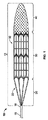
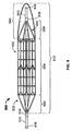
1つの一般的な態様において血栓治療器具が提供される。その血栓治療器具はサポートワイヤー、前記サポートワイヤーによって規定される軸線の周りに配置されるボディーフレーム部であって、前記ボディーフレーム部の長手方向の長さが前記ボディーフレーム部の外径の少なくとも2倍の長さであることを特徴とする前記ボディーフレーム部、前記ボディーフレーム部から前記サポートワイヤーに結合しているカラーまで延びている1本以上のテザーを含むテザー部、及び前記ボディーフレーム部から延びているフィルター部を備える。 In one general aspect, a thrombus treatment device is provided. The thrombus treatment instrument is a support wire, a body frame portion disposed around an axis defined by the support wire, and a longitudinal length of the body frame portion is at least 2 of an outer diameter of the body frame portion. A body frame portion, a tether portion including one or more tethers extending from the body frame portion to a collar coupled to the support wire, and the body frame portion An extending filter part is provided.
様々な実施形態において、前記ボディーフレーム部の長手方向の長さは前記ボディーフレーム部の外径の少なくとも3倍の長さであり得る。前記ボディーフレーム部の長手方向の長さは前記ボディーフレーム部の外径の少なくとも4倍の長さであり得る。前記ボディーフレーム部の長手方向の長さは前記ボディーフレーム部の外径の少なくとも5倍の長さであり得る。前記フィルター部の長手方向の長さは前記ボディーフレーム部の長手方向の長さの半分以下であり得る。前記の1本以上のテザーは、外転して前記の1本以上のテザーが前記ボディーフレーム部によって規定される領域内に実質的に存在する構成になるように構成され得る。前記の1本以上のテザーはニチノールから構成され得る。前記の1本以上のテザーは高分子材料から構成され得る。前記器具は、それぞれ前記ボディーフレーム部から前記サポートワイヤーに結合している前記カラーまで延びている複数のテザーを含むことができる。前記の複数のテザーの各テザーは、外転して前記の複数のテザーの各テザーが前記ボディーフレーム部によって規定される領域内に実質的に存在する構成になるように構成され得る。前記フィルター部は前記ボディーフレーム部と実質的に重ならなくてよい。前記ボディーフレーム部は前記ボディーフレーム部の長手方向の長さに沿って少なくとも3列に配置された複数の開放型セルを規定することができ、前記フィルター部は前記の少なくとも3列のうちの最大でも1列によって前記ボディーフレーム部と重なることができ、前記フィルター部は前記ボディーフレーム部の残りの部分と重ならなくてよい。前記ボディーフレーム部は前記ボディーフレーム部の長手方向の長さに沿って3列から10列までの開放型セルを規定することができる。前記フィルター部は前記ボディーフレーム部の長手方向の長さの20%以下と重なることができる。前記の1本以上のテザーが前記ボディーフレーム部の近位末端から延びてよく、且つ、前記フィルター部が前記ボディーフレーム部の遠位末端から延びてよい。 In various embodiments, the longitudinal length of the body frame portion may be at least three times the outer diameter of the body frame portion. The length of the body frame portion in the longitudinal direction may be at least four times the outer diameter of the body frame portion. The length of the body frame portion in the longitudinal direction may be at least five times the outer diameter of the body frame portion. The length of the filter part in the longitudinal direction may be less than or equal to half the length of the body frame part in the longitudinal direction. The one or more tethers may be configured to abduct so that the one or more tethers are substantially present in a region defined by the body frame portion. The one or more tethers may be composed of nitinol. The one or more tethers may be composed of a polymeric material. The appliance may include a plurality of tethers each extending from the body frame portion to the collar coupled to the support wire. Each tether of the plurality of tethers may be configured to be abducted so that each tether of the plurality of tethers substantially exists within an area defined by the body frame portion. The filter portion may not substantially overlap the body frame portion. The body frame part may define a plurality of open-type cells arranged in at least three rows along the length of the body frame part in the longitudinal direction, and the filter part is a maximum of the at least three rows. However, it can overlap with the body frame part by one row, and the filter part does not have to overlap the remaining part of the body frame part. The body frame part may define 3 to 10 open cells along the length of the body frame part in the longitudinal direction. The filter part may overlap with 20% or less of the length of the body frame part in the longitudinal direction. The one or more tethers may extend from a proximal end of the body frame portion, and the filter portion may extend from a distal end of the body frame portion.
別の一般的な態様において血栓を治療する方法が提供される。その方法は、カテーテルを患者に導入し、前記カテーテルの遠位末端を治療部位まで前進させること、前記カテーテルのルーメンを通して血栓治療器具を前進させること、前記ボディーフレーム部が前記治療部位にある血栓の少なくとも一部と大体並ぶ位置に前記カテーテルの前記ルーメン内の前記血栓治療器具を配置すること、及び前記カテーテルを近位方向に後退させることを含み、前記カテーテルの前記近位方向の後退に反応して前記ボディーフレーム部が前記血栓中に埋まるほど充分な半径方向力で拡張することを特徴とする。その血栓治療器具は(a)ボディーフレーム部、(b)前記ボディーフレーム部からサポートワイヤーに結合しているカラーまで延びている1本以上のテザーを含むテザー部、及び(c)前記ボディーフレーム部から延びているフィルター部を備え、前記ボディーフレーム部の長手方向の長さが前記ボディーフレーム部の外径の少なくとも2倍の長さであることを特徴とする。 In another general aspect, a method of treating a thrombus is provided. The method includes introducing a catheter into a patient, advancing the distal end of the catheter to a treatment site, advancing a thrombus treatment instrument through the lumen of the catheter, and a thrombus with the body frame portion at the treatment site. Locating the thrombus treatment device within the lumen of the catheter at a position approximately aligned with at least a portion, and retracting the catheter in a proximal direction, responsive to the proximal retraction of the catheter. The body frame portion is expanded with a radial force sufficient to be buried in the thrombus. The thrombus treatment device includes (a) a body frame portion, (b) a tether portion including one or more tethers extending from the body frame portion to a collar coupled to a support wire, and (c) the body frame portion. The body frame portion has a length in the longitudinal direction that is at least twice the outer diameter of the body frame portion.
様々な実施形態において、前記ボディーフレーム部は、前記ボディーフレーム部が拡張し、前記血栓に接触すると前記血栓を貫いて、又は前記血栓の付近に流路を開けるように構成され得る。前記フィルター部は前記ボディーフレーム部の前記拡張によって移動させられた血栓細粒を捕捉するように構成され得る。前記方法は前記フィルター部を血栓形成性物質又は自己血液で前処理することをさらに含むことができる。前記血栓治療器具は、前記の血栓形成性物質又は自己血液が前記フィルター部を介して血流を制限している間にオクルーダーとして作用し得る。前記方法は前記血栓まで血栓溶解薬を送達することをさらに含むことができる。 In various embodiments, the body frame portion may be configured to extend through the thrombus or open a flow path in the vicinity of the thrombus when the body frame portion expands and contacts the thrombus. The filter part may be configured to capture thrombotic granules moved by the expansion of the body frame part. The method may further include pretreating the filter portion with a thrombus-forming substance or autologous blood. The thrombus treatment device can act as an occluder while the thrombus-forming substance or autologous blood restricts blood flow through the filter portion. The method can further include delivering a thrombolytic agent to the thrombus.
別の一般的な態様において別の血栓治療器具が提供される。その血栓治療器具はサポートチューブ、前記サポートチューブによって規定される軸線の周りに配置されるボディーフレーム部であって、近位末端と遠位末端を含む前記ボディーフレーム部、前記ボディーフレーム部の遠位末端から延びているフィルター部、及びそれぞれ第1末端と第2末端を有する複数のテザーを備え、前記の複数のテザーのそれぞれの前記第1末端が前記サポートチューブの近位末端から外に延びており、前記テザーが前記サポートチューブのルーメンを通って前記サポートチューブの遠位末端から外に延びており、且つ、前記ボディーフレーム部の遠位末端の近くで前記ボディーフレーム部と係合し、且つ、前記ボディーフレーム部の近位末端まで延びており、前記の複数のテザーのそれぞれの前記第2末端が前記ボディーフレーム部の近位末端の近くで前記ボディーフレーム部に結合していることを特徴とする。 In another general aspect, another thrombus treatment device is provided. The thrombus treatment instrument includes a support tube, a body frame portion disposed around an axis defined by the support tube, the body frame portion including a proximal end and a distal end, and a distal end of the body frame portion A filter portion extending from the distal end, and a plurality of tethers each having a first end and a second end, each first end of the plurality of tethers extending outward from a proximal end of the support tube. The tether extends out of the distal end of the support tube through the lumen of the support tube and engages the body frame portion near the distal end of the body frame portion; and Extending to the proximal end of the body frame portion, and the second end of each of the plurality of tethers is Wherein the near the proximal end of Ifuremu portion attached to said body frame portion.
様々な実施形態において、前記の複数のテザーの各テザーは前記ボディーフレーム部の近位末端の近くの前記ボディーフレーム部の周りにループを形成することができる。前記の複数のテザーのそれぞれの前記第1末端に加えられた近位方向に向けられた力によって、前記ボディーフレーム部の遠位末端と前記ボディーフレーム部の近位末端が前記サポートチューブによって規定される前記軸線に向かって半径方向に折りたたまれ得る。前記の複数のテザーは前記ボディーフレーム部の近位末端の近くの前記ボディーフレーム部の周りに集団でループを形成することができる。前記の複数のテザーのそれぞれの前記第1末端に加えられた近位方向に向けられた力によって、前記ボディーフレーム部の遠位末端と前記ボディーフレーム部の近位末端が前記サポートチューブによって規定される前記長手方向の軸線に向かって半径方向に折りたたまれ得る。 In various embodiments, each tether of the plurality of tethers can form a loop around the body frame portion near a proximal end of the body frame portion. The distal end of the body frame portion and the proximal end of the body frame portion are defined by the support tube by a proximally directed force applied to the first end of each of the plurality of tethers. And can be folded radially toward the axis. The plurality of tethers may collectively form a loop around the body frame portion near a proximal end of the body frame portion. The distal end of the body frame portion and the proximal end of the body frame portion are defined by the support tube by a proximally directed force applied to the first end of each of the plurality of tethers. And can be folded radially towards the longitudinal axis.
別の一般的な態様において血栓を治療する別の方法が提供される。その方法は、カテーテルを患者に導入し、前記カテーテルの遠位末端を治療部位まで前進させること、前記カテーテルのルーメンを通して血栓治療器具を前進させること、前記ボディーフレーム部が前記治療部位にある血栓の少なくとも一部と大体並ぶ位置に前記カテーテルの前記ルーメン内の前記血栓治療器具を配置すること、及び前記カテーテルを近位方向に後退させることを含み、前記カテーテルの前記近位方向の後退に反応して前記ボディーフレーム部が前記血栓中に埋まるほど充分な半径方向力で拡張することを特徴とする。その血栓治療器具は(a)サポートチューブ、(b)前記サポートチューブによって規定される軸線の周りに配置されるボディーフレーム部であって、近位末端と遠位末端を含む前記ボディーフレーム部、(c)前記ボディーフレーム部の遠位末端から延びているフィルター部、及び(d)それぞれ第1末端と第2末端を有する複数のテザーを備え、前記の複数のテザーのそれぞれの前記第1末端が前記サポートチューブの近位末端から外に延びており、前記テザーが前記サポートチューブのルーメンを通って前記サポートチューブの遠位末端から外に延びており、且つ、前記ボディーフレーム部の遠位末端の近くで前記ボディーフレーム部と係合し、且つ、前記ボディーフレーム部の近位末端まで延びており、前記の複数のテザーのそれぞれの前記第2末端が前記ボディーフレーム部の近位末端の近くで前記ボディーフレーム部に結合していることを特徴とする。 In another general aspect, another method of treating a thrombus is provided. The method includes introducing a catheter into a patient, advancing the distal end of the catheter to a treatment site, advancing a thrombus treatment instrument through the lumen of the catheter, and a thrombus with the body frame portion at the treatment site. Locating the thrombus treatment device within the lumen of the catheter at a position approximately aligned with at least a portion, and retracting the catheter in a proximal direction, responsive to the proximal retraction of the catheter. The body frame portion is expanded with a radial force sufficient to be buried in the thrombus. The thrombus treatment device comprises: (a) a support tube; (b) a body frame portion disposed about an axis defined by the support tube, the body frame portion including a proximal end and a distal end; c) a filter portion extending from a distal end of the body frame portion, and (d) a plurality of tethers each having a first end and a second end, wherein the first ends of each of the plurality of tethers are Extending from a proximal end of the support tube, the tether extending through a lumen of the support tube and out of a distal end of the support tube, and at a distal end of the body frame portion Engaging the body frame portion in the vicinity and extending to a proximal end of the body frame portion, each of the plurality of tethers. Wherein the second end of is attached to the body frame portion near the proximal end of the body frame portion.
様々な実施形態において、前記ボディーフレーム部は、前記ボディーフレーム部が拡張し、前記血栓に接触すると前記血栓を貫いて流路を開けるように構成され得る。前記フィルター部は前記ボディーフレーム部の前記拡張によって移動させられた血栓細粒を捕捉するように構成され得る。前記方法は前記フィルター部を血栓形成性物質又は自己血液で前処理することをさらに含むことができる。前記血栓治療器具は、前記の血栓形成性物質又は自己血液が前記フィルター部を介して血流を制限している間にオクルーダーとして作用し得る。前記方法は前記血栓まで血栓溶解薬を送達することをさらに含むことができる。 In various embodiments, the body frame portion may be configured to open a flow path through the thrombus when the body frame portion expands and contacts the thrombus. The filter part may be configured to capture thrombotic granules moved by the expansion of the body frame part. The method may further include pretreating the filter portion with a thrombus-forming substance or autologous blood. The thrombus treatment device can act as an occluder while the thrombus-forming substance or autologous blood restricts blood flow through the filter portion. The method can further include delivering a thrombolytic agent to the thrombus.
別の一般的な態様において別の血栓治療器具が提供される。その血栓治療器具はサポートワイヤー、前記サポートワイヤーによって規定される軸線の周りに配置されるボディーフレーム部であって、前記ボディーフレーム部の長手方向の長さが前記ボディーフレーム部の外径の少なくとも2倍の長さであることを特徴とする前記ボディーフレーム部、それぞれ前記ボディーフレーム部の近位末端から前記サポートワイヤーに結合しているカラーまで延びている1本以上のテザー、及び前記ボディーフレーム部の遠位末端から延びているフィルター部を備える。前記ボディーフレーム部は前記ボディーフレーム部の長手方向の長さに沿って少なくとも3列に配置された複数の開放型セルを規定し、且つ、前記フィルター部は前記の少なくとも3列のうちの最大でも1列と重なり、残りの列と重ならない。 In another general aspect, another thrombus treatment device is provided. The thrombus treatment instrument is a support wire, a body frame portion disposed around an axis defined by the support wire, and a longitudinal length of the body frame portion is at least 2 of an outer diameter of the body frame portion. The body frame part, one or more tethers extending from the proximal end of the body frame part to a collar connected to the support wire, and the body frame part A filter portion extending from the distal end of the filter. The body frame portion defines a plurality of open-type cells arranged in at least three rows along the length of the body frame portion in the longitudinal direction, and the filter portion is at most of the at least three rows. It overlaps with one row and does not overlap with the remaining rows.
様々な実施形態において、前記ボディーフレーム部の長手方向の長さは前記ボディーフレーム部の外径の少なくとも3倍の長さであり得る。前記ボディーフレーム部の長手方向の長さは前記ボディーフレーム部の外径の少なくとも4倍の長さであり得る。前記ボディーフレーム部の長手方向の長さは前記ボディーフレーム部の外径の少なくとも5倍の長さであり得る。 In various embodiments, the longitudinal length of the body frame portion may be at least three times the outer diameter of the body frame portion. The length of the body frame portion in the longitudinal direction may be at least four times the outer diameter of the body frame portion. The length of the body frame portion in the longitudinal direction may be at least five times the outer diameter of the body frame portion.
別の一般的な態様において、血栓を治療する別の方法が提供される。その方法は、カテーテルを患者に挿入し、前記カテーテルの遠位末端を治療部位まで前進させること、前記カテーテルのルーメンを通して血栓治療器具を前進させること、前記ボディーフレーム部が前記治療部位にある血栓の少なくとも一部と大体並ぶ位置に前記カテーテルの前記ルーメン内の前記血栓治療器具を配置すること、及び前記カテーテルを近位方向に後退させることを含み、前記カテーテルの前記近位方向の後退に反応して前記ボディーフレーム部が前記血栓中に埋まるほど充分な半径方向力で拡張することを特徴とする。その血栓治療器具は(a)外径の少なくとも2倍の長さの長手方向の長さを有するボディーフレーム部、(b)それぞれ前記ボディーフレーム部からサポートワイヤーに結合しているカラーまで延びている1本以上のテザーを含むテザー部、及び(c)前記ボディーフレーム部から延びているフィルター部を備え、前記ボディーフレーム部が前記ボディーフレーム部の長手方向の長さに沿って少なくとも3列に配置された複数の開放型セルを規定し、且つ、前記フィルター部が前記の少なくとも3列のうちの最大でも1列と重なり、前記の少なくとも3列の残りの列と重ならないことを特徴とする。 In another general aspect, another method of treating a thrombus is provided. The method includes inserting a catheter into a patient and advancing the distal end of the catheter to a treatment site, advancing a thrombus treatment instrument through the lumen of the catheter, and a thrombus with the body frame portion at the treatment site. Locating the thrombus treatment device within the lumen of the catheter at a position approximately aligned with at least a portion, and retracting the catheter in a proximal direction, responsive to the proximal retraction of the catheter. The body frame portion is expanded with a radial force sufficient to be buried in the thrombus. The thrombus treatment device extends to (a) a body frame portion having a length in the longitudinal direction that is at least twice the outer diameter, and (b) each extending from the body frame portion to a collar coupled to a support wire. A tether portion including one or more tethers; and (c) a filter portion extending from the body frame portion, wherein the body frame portions are arranged in at least three rows along a length in a longitudinal direction of the body frame portion. The plurality of open-type cells are defined, and the filter unit overlaps at least one of the at least three columns and does not overlap the at least three remaining columns.
様々な実施形態において、前記ボディーフレーム部は、前記ボディーフレーム部が拡張し、前記血栓に接触すると前記血栓を貫いて流路を開けるように構成され得る。前記フィルター部は、前記ボディーフレーム部の前記拡張によって移動させられた血栓細粒を捕捉するように構成され得る。前記方法は前記フィルター部を血栓形成性物質又は自己血液で前処理することをさらに含むことができる。前記血栓治療器具は、前記の血栓形成性物質又は自己血液が前記フィルター部を介して血流を制限している間にオクルーダーとして作用し得る。前記方法は前記血栓まで血栓溶解薬を送達することをさらに含むことができる。 In various embodiments, the body frame portion may be configured to open a flow path through the thrombus when the body frame portion expands and contacts the thrombus. The filter part may be configured to capture thrombus granules that have been moved by the expansion of the body frame part. The method may further include pretreating the filter portion with a thrombus-forming substance or autologous blood. The thrombus treatment device can act as an occluder while the thrombus-forming substance or autologous blood restricts blood flow through the filter portion. The method can further include delivering a thrombolytic agent to the thrombus.
別の一般的な態様において別の血栓治療器具が提供される。その血栓治療器具は、サポートチューブ、前記サポートチューブによって規定される軸線の周りに配置されるボディーフレーム部であって、近位末端と遠位末端を含む前記ボディーフレーム部、前記ボディーフレーム部の遠位末端から延びているフィルター部、それぞれ第1末端と第2末端を有する1本以上の近位テザーであって、前記の1本以上の近位テザーのそれぞれの前記第1末端が前記サポートチューブに結合しており、且つ、前記の1本以上の近位テザーのそれぞれの前記第2末端が前記ボディーフレーム部に結合していることを特徴とする前記の1本以上の近位テザー、及びそれぞれ第1末端と第2末端を有する1本以上の遠位テザーであって、前記の1本以上の遠位テザーのそれぞれの前記第1末端が前記サポートチューブに結合しており、且つ、前記の1本以上の遠位テザーのそれぞれの前記第2末端が前記ボディーフレーム部に結合していることを特徴とする前記の1本以上の遠位テザーを備える。 In another general aspect, another thrombus treatment device is provided. The thrombus treatment instrument includes a support tube, a body frame portion disposed around an axis defined by the support tube, the body frame portion including a proximal end and a distal end, and a distal portion of the body frame portion. One or more proximal tethers each having a first end and a second end extending from the distal end, each said first end of said one or more proximal tethers being said support tube One or more proximal tethers, wherein the second end of each of the one or more proximal tethers is coupled to the body frame portion; and One or more distal tethers each having a first end and a second end, each first end of the one or more distal tethers being in the support tube; Combined and and comprises the one or more distal tether, characterized in that each of said second ends of one or more distal tether of said is attached to the body frame portion.
様々な実施形態において、前記の1本以上の遠位テザーは移動可能であるように前記サポートチューブに結合することができ、且つ、前記の1本以上の近位テザーは固定的に前記サポートチューブに結合することができる。前記の1本以上の遠位テザーは固定的に前記サポートチューブに結合することができ、且つ、前記の1本以上の近位テザーは移動可能であるように前記サポートチューブに結合することができる。前記サポートチューブの遠位末端は、前記遠位テザーが前記サポートチューブに結合している位置から遠位方向に位置し得る。前記サポートチューブの遠位末端は前記フィルター部から遠位方向に位置し得る。前記遠位テザーは前記フィルター部によって規定される内部空間内に実質的に位置し得る。前記ボディーフレーム部の長手方向の長さは前記ボディーフレーム部の外径の少なくとも2倍の長さであり得る。前記ボディーフレーム部の長手方向の長さは前記ボディーフレーム部の外径の少なくとも3倍の長さであり得る。前記ボディーフレーム部の長手方向の長さは前記ボディーフレーム部の外径の少なくとも4倍の長さであり得る。前記フィルター部の長手方向の長さは前記ボディーフレーム部の長手方向の長さの半分以下であり得る。前記の1本以上の近位テザーのそれぞれの前記第2末端は前記ボディーフレーム部の近位末端に結合することができ、且つ、前記の1本以上の遠位テザーのそれぞれの前記第2末端は前記ボディーフレーム部の遠位末端に結合することができる。 In various embodiments, the one or more distal tethers can be coupled to the support tube to be movable, and the one or more proximal tethers are fixedly attached to the support tube. Can be combined. The one or more distal tethers can be fixedly coupled to the support tube, and the one or more proximal tethers can be coupled to the support tube such that they are movable. . The distal end of the support tube may be located distally from the position where the distal tether is coupled to the support tube. The distal end of the support tube may be located distally from the filter portion. The distal tether can be located substantially within an interior space defined by the filter portion. The length of the body frame portion in the longitudinal direction may be at least twice the outer diameter of the body frame portion. The length of the body frame portion in the longitudinal direction may be at least three times the outer diameter of the body frame portion. The length of the body frame portion in the longitudinal direction may be at least four times the outer diameter of the body frame portion. The length of the filter part in the longitudinal direction may be less than or equal to half the length of the body frame part in the longitudinal direction. The second end of each of the one or more proximal tethers can be coupled to the proximal end of the body frame portion and the second end of each of the one or more distal tethers Can be coupled to the distal end of the body frame.
別の一般的な態様において血栓を治療するための別の方法が提供される。その方法は、カテーテルを患者に挿入し、前記カテーテルの遠位末端を治療部位まで前進させること、前記カテーテルのルーメンを通して血栓治療器具を前進させること、前記ボディーフレーム部が前記治療部位にある血栓の少なくとも一部と大体並ぶ位置に前記カテーテルの前記ルーメン内の前記血栓治療器具を配置すること、及び前記カテーテルを近位方向に後退させることを含み、前記カテーテルの前記近位方向の後退に反応して前記ボディーフレーム部が前記血栓中に埋まるほど充分な半径方向力で拡張することを特徴とする。その血栓治療器具はサポートチューブ、前記サポートチューブによって規定される軸線の周りに配置されるボディーフレーム部であって、近位末端と遠位末端を含む前記ボディーフレーム部、前記ボディーフレーム部の遠位末端から延びているフィルター部、それぞれ第1末端と第2末端を有する1本以上の近位テザーであって、前記の1本以上の近位テザーのそれぞれの前記第1末端が前記サポートチューブに結合しており、且つ、前記の1本以上の近位テザーのそれぞれの前記第2末端が前記ボディーフレーム部に結合していることを特徴とする前記近位テザー、及びそれぞれ第1末端と第2末端を有する1本以上の遠位テザーであって、前記の1本以上の遠位テザーのそれぞれの前記第1末端が前記サポートチューブに結合しており、且つ、前記の1本以上の遠位テザーのそれぞれの前記第2末端が前記ボディーフレーム部に結合していることを特徴とする前記遠位テザーを備える。 In another general aspect, another method for treating a thrombus is provided. The method includes inserting a catheter into a patient and advancing the distal end of the catheter to a treatment site, advancing a thrombus treatment instrument through the lumen of the catheter, and a thrombus with the body frame portion at the treatment site. Locating the thrombus treatment device within the lumen of the catheter at a position approximately aligned with at least a portion, and retracting the catheter in a proximal direction, responsive to the proximal retraction of the catheter. The body frame portion is expanded with a radial force sufficient to be buried in the thrombus. The thrombus treatment instrument includes a support tube, a body frame portion disposed around an axis defined by the support tube, the body frame portion including a proximal end and a distal end, and a distal end of the body frame portion One or more proximal tethers each having a first end and a second end extending from a distal end, wherein the first end of each of the one or more proximal tethers is in the support tube; The proximal tether, wherein the second end of each of the one or more proximal tethers is coupled to the body frame portion; and the first end and the first end of the proximal tether, respectively. One or more distal tethers having two ends, wherein the first end of each of the one or more distal tethers is coupled to the support tube; One comprises the distal tether, characterized in that each of said second ends of one or more distal tether of said is attached to the body frame portion.
様々な実施形態において、前記ボディーフレーム部は、前記ボディーフレーム部が拡張し、前記血栓に接触すると前記血栓を貫いて流路を開けるように構成され得る。前記フィルター部は前記ボディーフレーム部の前記拡張によって移動させられた血栓細粒を捕捉するように構成され得る。 In various embodiments, the body frame portion may be configured to open a flow path through the thrombus when the body frame portion expands and contacts the thrombus. The filter part may be configured to capture thrombotic granules moved by the expansion of the body frame part.
別の一般的な態様において別の血栓治療器具が提供される。その血栓治療器具はサポートワイヤー、前記サポートワイヤーによって規定される軸線の周りに配置されるボディーフレーム部であって、1つ以上の間隙を規定する前記ボディーフレーム部、前記ボディーフレーム部から前記サポートワイヤーに結合しているカラーまで延びている1本以上のテザーを含むテザー部、及び前記ボディーフレーム部から延びているフィルター部を備え、前記カラーが前記のボディーフレーム部又はフィルター部の内部領域内に実質的に位置するときに前記サポートワイヤーの関節接合(articulation)が前記の1本以上からなるテザーの一部を可動域(運動域)の中で動かすことになり、且つ、前記ボディーフレーム部に対して実質的な運動を伝えないことを特徴とする。 In another general aspect, another thrombus treatment device is provided. The thrombus treatment instrument is a support wire, a body frame portion arranged around an axis defined by the support wire, the body frame portion defining one or more gaps, and the support wire from the body frame portion A tether portion including one or more tethers extending to a collar coupled to the filter, and a filter portion extending from the body frame portion, wherein the collar is within an inner region of the body frame portion or the filter portion. When substantially positioned, articulation of the support wire will move a portion of the one or more tethers within a range of motion (movement range), and the body frame portion It is characterized by not transmitting substantial movements.
様々な実施形態において、前記サポートの前記関節接合は前記サポートワイヤーの回転運動であり得、且つ、前記ボディーフレーム部の実質的にゼロの運動を引き起こすことができる。前記器具は前記サポートワイヤーの前記回転運動に関して前記サポートワイヤーの0°回転と関連するニュートラルポジション、前記サポートワイヤーの時計回り回転と関連する第1トルクポジション、及び前記サポートワイヤーの反時計回り回転と関連する第2トルクポジションを含むことができる。前記器具が前記ニュートラルポジションにあるときに前記の1本以上のテザーは「S字」型形状を備えることができる。前記器具が前記第1トルクポジションにあるときに前記の1本以上のテザーは第1の全般的に直線的な形状を備えることができ、前記器具が前記第2トルクポジションにあるときに前記の1本以上のテザーは第2の全般的に直線的な形状を備えることができる。前記器具が前記ニュートラルポジションにあるときに前記の1本以上のテザーはループ構成を備えることができる。前記の1本以上のテザーは、前記サポートワイヤーが関節接合されると前記ボディーフレーム部によって規定される前記の1つ以上の間隙を通って突き出ている血栓性物質の少なくとも一部を切断するように構成され得る。前記サポートワイヤーの前記関節接合は最大で270°までの前記サポートワイヤーの回転運動であり得、且つ、前記の1本以上のテザーの前記一部を可動域の中で動かすことができ、前記ボディーフレーム部に対して実質的な運動を伝えずにいることができる。前記サポートワイヤーの前記関節接合は最大で180°までの前記サポートワイヤーの回転運動であり得、且つ、前記の1本以上のテザーの前記一部を可動域の中で動かすことができ、前記ボディーフレーム部に対して実質的な運動を伝えずにいることができる。前記サポートの前記関節接合は最大で360°までの前記サポートワイヤーの回転運動であり得、且つ、前記ボディーフレーム部の実質的にゼロの運動を引き起こすことができる。 In various embodiments, the articulation of the support can be a rotational movement of the support wire and can cause a substantially zero movement of the body frame portion. The instrument is associated with a neutral position associated with 0 ° rotation of the support wire with respect to the rotational movement of the support wire, a first torque position associated with clockwise rotation of the support wire, and counterclockwise rotation of the support wire. A second torque position may be included. The one or more tethers may comprise an “S” shape when the device is in the neutral position. The one or more tethers can have a first generally linear shape when the instrument is in the first torque position, and when the instrument is in the second torque position. The one or more tethers can have a second generally linear shape. The one or more tethers may comprise a loop configuration when the instrument is in the neutral position. The one or more tethers may cut at least a portion of the thrombotic material protruding through the one or more gaps defined by the body frame when the support wire is articulated. Can be configured. The articulation of the support wire can be a rotational movement of the support wire up to 270 °, and the part of the one or more tethers can be moved within a range of motion, the body It is possible to transmit no substantial movement to the frame portion. The articulation of the support wire can be a rotational movement of the support wire up to 180 °, and the part of the one or more tethers can be moved within a range of motion, the body It is possible to transmit no substantial movement to the frame portion. The articulation of the support can be a rotational movement of the support wire up to 360 ° and can cause a substantially zero movement of the body frame part.
別の一般的な態様において血栓を治療する別の方法が提供される。その方法は、近位末端と遠位末端を有するカテーテルを患者に挿入し、前記カテーテルの遠位末端を治療部位まで前進させること、血栓治療器具を、前記カテーテルのルーメンを通して前記治療部位まで前進させること、前記ボディーフレーム部が前記治療部位にある血栓の少なくとも一部と大体並ぶ位置に前記カテーテルの前記ルーメン内の前記血栓治療器具を配置し、前記カテーテルを近位方向に後退させること、前記サポートワイヤーに遠位方向に向けられた力を加えて前記カラーを実質的に前記ボディーフレーム部の内部領域内の位置又は実質的に前記フィルター部の内部領域内の位置まで前進させること、及び前記サポートワイヤーを回転させて動かすことを含み、前記血栓を解離するように構成されている前記の1本以上のテザーの少なくとも一部の回転運動が前記サポートワイヤーの前記回転動作によって引き起こされることを特徴とする。その血栓治療器具は(a)1つ以上の間隙を規定するボディーフレーム部、(b)前記ボディーフレーム部からサポートワイヤーに結合しているカラーまで延びている1本以上のテザーを含むテザー部、及び(c)前記ボディーフレーム部から延びているフィルター部を備える。 In another general aspect, another method of treating a thrombus is provided. The method inserts a catheter having a proximal end and a distal end into a patient, advances the distal end of the catheter to a treatment site, and advances a thrombus treatment device through the lumen of the catheter to the treatment site. Disposing the thrombus treatment instrument in the lumen of the catheter at a position where the body frame portion is substantially aligned with at least a part of the thrombus at the treatment site, and retracting the catheter in the proximal direction; Applying a distally directed force to the wire to advance the collar to a position substantially within the interior region of the body frame portion or substantially within the interior region of the filter portion; and the support One or more tethers configured to dissociate the thrombus, including rotating and moving a wire At least a portion of the rotational movement of the is equal to or caused by the rotation of the support wire. The thrombus treatment device comprises: (a) a body frame portion defining one or more gaps; (b) a tether portion including one or more tethers extending from the body frame portion to a collar coupled to a support wire; And (c) a filter portion extending from the body frame portion.
様々な実施形態において、前記の1本以上のテザーの前記一部の前記回転運動は前記ボディーフレーム部によって規定される1つ以上の間隙を通って突き出ている血栓性物質を切断し得る。前記サポートワイヤーの回転運動は前記ボディーフレーム部に対して運動を実質的に伝えることなく前記の1本以上のテザーの前記一部を可動域の中で動かすことができる。約360°の前記サポートワイヤーの前記回転運動は前記ボディーフレーム部の実質的にゼロの運動を引き起こすことができる。約270°の前記サポートワイヤーの回転運動は前記ボディーフレーム部に対して運動を実質的に伝えることなく前記の1本以上のテザーの前記一部を可動域の中で動かすことができる。最大で少なくとも約270°までの前記サポートワイヤーの前記回転運動は前記ボディーフレーム部の実質的にゼロの運動を引き起こすことができる。約180°の前記サポートワイヤーの回転運動は前記ボディーフレーム部に対して運動を実質的に伝えることなく前記の1本以上のテザーの前記一部を可動域の中で動かすことができる。前記サポートワイヤーの前記回転運動は前記ボディーフレーム部の実質的にゼロの運動を引き起こすことができる。前記器具は前記回転動作に関して前記サポートワイヤーの0°回転と関連するニュートラルポジション、前記サポートワイヤーの時計回り回転と関連する第1トルクポジション、及び前記サポートワイヤーの反時計回り回転と関連する第2トルクポジションを含むことができる。前記器具が前記ニュートラルポジションにあるときに前記の1本以上のテザーは「S字」型形状を備えることができる。前記器具が前記第1トルクポジションにあるときに前記の1本以上のテザーは第1の全般的に直線的な形状を備えることができ、前記器具が前記第2トルクポジションにあるときに前記の1本以上のテザーは第2の全般的に直線的な形状を備えることができる。前記器具が前記ニュートラルポジションにあるときに前記の1本以上のテザーはループ構成を備えることができる。前記の1本以上のテザーは、前記サポートワイヤーを回転すると前記ボディーフレーム部によって規定される前記の1つ以上の間隙を通って突き出ている血栓性物質を切断するように構成され得る。 In various embodiments, the rotational movement of the portion of the one or more tethers can cut thrombotic material protruding through one or more gaps defined by the body frame portion. The rotational motion of the support wire can move the portion of the one or more tethers within a range of motion without substantially transmitting motion to the body frame portion. The rotational movement of the support wire of about 360 ° can cause substantially zero movement of the body frame portion. A rotational movement of the support wire of about 270 ° can move the portion of the one or more tethers within a range of motion without substantially transferring movement to the body frame portion. The rotational movement of the support wire up to at least about 270 ° can cause substantially zero movement of the body frame portion. A rotational movement of the support wire of about 180 ° can move the portion of the one or more tethers within a range of motion without substantially transferring movement to the body frame portion. The rotational movement of the support wire can cause substantially zero movement of the body frame portion. The instrument has a neutral position associated with 0 ° rotation of the support wire with respect to the rotational movement, a first torque position associated with clockwise rotation of the support wire, and a second torque associated with counterclockwise rotation of the support wire. Can contain positions. The one or more tethers may comprise an “S” shape when the device is in the neutral position. The one or more tethers can have a first generally linear shape when the instrument is in the first torque position, and when the instrument is in the second torque position. The one or more tethers can have a second generally linear shape. The one or more tethers may comprise a loop configuration when the instrument is in the neutral position. The one or more tethers may be configured to cut thrombotic material protruding through the one or more gaps defined by the body frame portion as the support wire is rotated.
別の一般的な態様において血栓治療システムが提供される。その血栓治療システムは第1サポートチューブ、前記第1サポートチューブによって規定される軸線の周りに配置されるボディーフレーム部であって、1つ以上の間隙を規定する前記ボディーフレーム部、前記ボディーフレーム部から前記第1サポートチューブに結合しているカラーまで延びている1本以上のテザーを含むテザー部、及び第2サポートチューブに結合している安定化要素を備え、前記カラーが実質的に前記ボディーフレーム部の内部領域内に配置されているときに最大で360°までの前記第1サポートチューブの回転運動が前記の1本以上のテザーの一部を可動域の中で動かすことになり、且つ、前記ボディーフレーム部に対して実質的な運動を伝えないことを特徴とする。 In another general aspect, a thrombus treatment system is provided. The thrombus treatment system includes a first support tube, a body frame portion disposed around an axis defined by the first support tube, the body frame portion defining one or more gaps, and the body frame portion A tether portion including one or more tethers extending to a collar coupled to the first support tube, and a stabilizing element coupled to a second support tube, wherein the collar is substantially the body. Rotational movement of the first support tube up to 360 ° when disposed within the internal region of the frame portion will cause a portion of the one or more tethers to move within the range of motion; and The substantial motion is not transmitted to the body frame part.
様々な実施形態において、前記の1本以上のテザーは前記ボディーフレーム部の近位末端から延びてよい。前記の1本以上のテザーは前記ボディーフレーム部の遠位末端から延びてよい。前記の1本以上のテザーは、前記ボディーフレーム部によって規定される領域に進入している血栓性物質を前記第2サポートチューブに加えられた近位方向に向けられた力に反応して切断するように構成され得る。最大で270°までの前記第1サポートチューブの回転運動は、前記の1本以上のテザーの前記一部を可動域の中で動かすことができ、前記ボディーフレーム部に対して実質的な運動を伝えずにいることができる。最大で180°までの前記第1サポートチューブの回転運動は、前記の1本以上のテザーの前記一部を可動域の中で動かすことができ、前記ボディーフレーム部に対して実質的な運動を伝えずにいることができる。 In various embodiments, the one or more tethers may extend from a proximal end of the body frame portion. The one or more tethers may extend from a distal end of the body frame portion. The one or more tethers cut the thrombotic substance entering the region defined by the body frame portion in response to a force directed in the proximal direction applied to the second support tube. Can be configured as follows. The rotational movement of the first support tube up to 270 ° allows the part of the one or more tethers to move within the range of motion, and provides substantial movement relative to the body frame portion. You can stay away. The rotational movement of the first support tube up to 180 ° allows the part of the one or more tethers to move within the range of motion, and provides substantial movement relative to the body frame portion. You can stay away.
別の一般的な態様において血栓を治療する別の方法が提供される。その方法は、カテーテルを患者に挿入し、前記カテーテルの遠位末端を治療部位まで前進させること、血栓治療器具を、前記カテーテルのルーメンを通して前記治療部位まで前進させること、前記治療部位にある血栓の少なくとも一部から遠く離れて前記安定化要素が存在する位置まで前記第2サポートチューブを前進させること、前記血栓の少なくとも一部から近い位置に前記カテーテルの前記ルーメン内の前記ボディーフレームを配置すること、前記カテーテルを近位方向に後退させることによって前記ボディーフレーム部を拡張させること、遠位方向に向けられた力を前記第1サポートチューブに加えて前記カラーを前記ボディーフレーム部の内部の位置まで前進させること、近位方向に向けられた力を前記第2サポートチューブに加えることによって前記安定化要素を近位方向に移動させること、及び前記第1サポートチューブを回転させて動かすことを含み、前記第1サポートチューブの前記回転動作によって前記の1本以上のテザーの少なくとも一部の回転運動が引き起こされ、且つ、前記の1本以上のテザーが前記血栓を解離するように構成されていることを特徴とする。その血栓治療器具は(a)第1サポートチューブ、(b)前記第1サポートチューブによって規定される軸線の周りに配置されるボディーフレーム部、(c)前記ボディーフレーム部から前記第1サポートチューブに結合しているカラーまで延びている1本以上のテザーを含むテザー部であって、前記カラーが実質的に前記ボディーフレーム部の内部領域内に配置されているときに最大で360°までの前記第1サポートチューブの回転運動が前記の1本以上のテザーの一部を可動域の中で動かすことになり、且つ、前記ボディーフレーム部に対して運動を実質的に伝えないことを特徴とする前記テザー部、及び(d)第2サポートチューブに結合している安定化要素を備える。 In another general aspect, another method of treating a thrombus is provided. The method includes inserting a catheter into a patient and advancing the distal end of the catheter to a treatment site, advancing a thrombus treatment device through the catheter lumen to the treatment site, and removing a thrombus at the treatment site. Advancing the second support tube to a position at least far from at least a portion of the stabilizing element, and positioning the body frame within the lumen of the catheter at a location near at least a portion of the thrombus Expanding the body frame portion by retracting the catheter proximally, applying a distally directed force to the first support tube to move the collar to a position within the body frame portion. Advancing, applying a proximally directed force to the second support tube Moving the stabilization element in a proximal direction by rotating and moving the first support tube by rotating at least one of the one or more tethers by the rotational movement of the first support tube. Some rotational movement is caused and the one or more tethers are configured to dissociate the thrombus. The thrombus treatment instrument includes (a) a first support tube, (b) a body frame portion disposed around an axis defined by the first support tube, and (c) the body frame portion to the first support tube. A tether portion including one or more tethers extending to a connecting collar, wherein the collar is substantially up to 360 ° when the collar is disposed substantially within the interior region of the body frame portion. The rotational movement of the first support tube moves a part of the one or more tethers within a movable range, and does not substantially transmit the movement to the body frame part. The tether portion, and (d) a stabilizing element coupled to the second support tube.
様々な実施形態において、前記の1本以上のテザーの前記の少なくとも一部の前記回転運動は、前記安定化要素の前記近位方向の移動によって近位方向に移動させられた血栓性物質を解離することができる。前記器具は前記回転動作に関して前記第1サポートチューブの0°回転と関連するニュートラルポジション、前記第1サポートチューブの時計回り回転と関連する第1トルクポジション、及び前記第1サポートチューブの反対時計回り回転と関連する第2トルクポジションを含むことができる。前記器具が前記ニュートラルポジションにあるときに前記の1本以上のテザーは「S字」型形状を備えることができる。前記器具が前記第1トルクポジションにあるときに前記の1本以上のテザーは第1の全般的に直線的な形状を備えることができ、前記器具が前記第2トルクポジションにあるときに前記の1本以上のテザーは第2の全般的に直線的な形状を備えることができる。前記器具が前記ニュートラルポジションにあるときに前記の1本以上のテザーはループ構成を備えることができる。前記方法は、前記治療部位にある血栓の少なくとも一部から遠く離れて前記安定化要素が存在する位置まで前記第2サポートチューブを前進させた後に前記安定化要素に膨張媒体を供給して前記安定化要素の拡張を引き起こすことをさらに含むことができる。前記膨張媒体は液体、気体、ゲル、泡、及び固体のうちの1つであり得る。前記膨張媒体は造影剤を含むことができる。 In various embodiments, the rotational movement of the at least part of the one or more tethers dissociates the thrombotic material moved proximally by the proximal movement of the stabilizing element. can do. The instrument has a neutral position associated with 0 ° rotation of the first support tube with respect to the rotational movement, a first torque position associated with clockwise rotation of the first support tube, and counterclockwise rotation of the first support tube. A second torque position associated with the. The one or more tethers may comprise an “S” shape when the device is in the neutral position. The one or more tethers can have a first generally linear shape when the instrument is in the first torque position, and when the instrument is in the second torque position. The one or more tethers can have a second generally linear shape. The one or more tethers may comprise a loop configuration when the instrument is in the neutral position. The method includes the step of advancing the second support tube to a position where the stabilizing element is located far from at least a portion of the thrombus at the treatment site and then supplying an inflation medium to the stabilizing element to provide the stabilizing Can further include causing expansion of the visualization element. The expansion medium can be one of a liquid, a gas, a gel, a foam, and a solid. The expansion medium can include a contrast agent.
別の一般的な態様において別の血栓治療システムが提供される。その血栓治療システムは第1サポートチューブ、前記第1サポートチューブによって規定される軸線の周りに周方向に配置されるボディーフレーム部、前記ボディーフレーム部の近位部分から前記第1サポートチューブに結合している第1カラーまで延びている1本以上の第1テザーを含む第1テザー部、前記ボディーフレーム部の遠位部分から前記第1サポートチューブに結合している第2カラーまで延びている1本以上の第2テザーを含む第2テザー部、及び第2サポートチューブに結合している安定化要素を備え、前記第1カラーと前記第2カラーがそれぞれ前記ボディーフレーム部の内部領域内に位置するときに前記第1サポートチューブの回転運動が前記の1本以上の第1テザーと前記の1本以上の第2テザーの一部を可動域の中で動かすことになり、且つ、前記ボディーフレーム部に対して実質的な運動を伝えないことを特徴とする。 In another general aspect, another thrombus treatment system is provided. The thrombus treatment system is coupled to the first support tube from a first support tube, a body frame portion disposed circumferentially about an axis defined by the first support tube, and a proximal portion of the body frame portion. A first tether portion including one or more first tethers extending to a first collar extending from the distal portion of the body frame portion to a second collar coupled to the first support tube. A second tether portion including at least two second tethers, and a stabilizing element coupled to the second support tube, wherein the first collar and the second collar are each located in an inner region of the body frame portion. When the rotational movement of the first support tube causes the one or more first tethers and a part of the one or more second tethers to move within the range of motion. It will be moved, and characterized in that it does not carry substantial movement relative to said body frame portion.
様々な実施形態において、最大で360°までの前記第1サポートチューブの回転運動は前記の1本以上の第1テザーと前記の1本以上の第2テザーの一部を可動域の中で動かすことができ、且つ、前記ボディーフレーム部に対して実質的な運動を伝えずにいることができる。最大で180°までの前記第1サポートチューブの回転運動は前記の1本以上の第1テザーと前記の1本以上の第2テザーの一部を可動域の中で動かすことができ、且つ、前記ボディーフレーム部に対して実質的な運動を伝えずにいることができる。 In various embodiments, rotational movement of the first support tube up to 360 ° moves the one or more first tethers and a portion of the one or more second tethers within a range of motion. And it is possible to transmit no substantial motion to the body frame portion. Rotational movement of the first support tube up to 180 ° can move the one or more first tethers and a portion of the one or more second tethers within a range of motion; and It is possible to transmit no substantial movement to the body frame portion.
別の一般的な態様において血栓を治療する別の方法が提供される。その方法は、カテーテルを患者に挿入し、前記カテーテルの遠位末端を治療部位まで前進させること、血栓治療器具を、前記カテーテルのルーメンを通して前記治療部位まで前進させること、前記治療部位にある血栓の少なくとも一部から遠く離れて前記安定化要素が存在する位置まで前記第2サポートチューブを前進させること、前記血栓の少なくとも一部から近い位置に前記カテーテルの前記ルーメン内の前記ボディーフレームを配置すること、前記カテーテルを近位方向に後退させることによって前記ボディーフレーム部を拡張させること、前記第1カラーと前記第2カラーを前記ボディーフレーム部の前記内部領域内に配置すること、近位方向に向けられた力を前記第2サポートチューブに加えることによって前記安定化要素を近位方向に移動させること、及び前記第1サポートチューブを回転させて動かすことを含み、前記第1サポートチューブの前記回転動作によって前記の1本以上の第1テザーの一部と前記の1本以上の第2テザーの一部の回転運動が引き起こされ、且つ、前記の1本以上の第1テザーと前記の1本以上の第2テザーが前記血栓を解離するように構成されていることを特徴とする。その血栓治療器具は(a)第1サポートチューブ、(b)前記第1サポートチューブによって規定される軸線の周りに周方向に配置されるボディーフレーム部、(c)前記ボディーフレーム部の近位部分から前記第1サポートチューブに結合している第1カラーまで延びている1本以上の第1テザーを含む第1テザー部、(d)前記ボディーフレーム部の遠位部分から前記第1サポートチューブに結合している第2カラーまで延びている1本以上の第2テザーを含む第2テザー部であって、前記第1カラーと前記第2カラーがそれぞれ前記ボディーフレーム部の内部領域内に位置するときに最大で360°までの前記第1サポートチューブの回転運動が前記の1本以上の第1テザーと前記の1本以上の第2テザーの一部を可動域の中で動かすことになり、且つ、前記ボディーフレーム部に対して実質的な運動を伝えないことを特徴とする前記第1テザー部と前記第2テザー部、及び(e)第2サポートチューブに結合している安定化要素を備える。 In another general aspect, another method of treating a thrombus is provided. The method includes inserting a catheter into a patient and advancing the distal end of the catheter to a treatment site, advancing a thrombus treatment instrument through the catheter lumen to the treatment site, and removing a thrombus at the treatment site. Advancing the second support tube to a position at least far from at least a portion of the stabilizing element, and positioning the body frame within the lumen of the catheter at a location near at least a portion of the thrombus Expanding the body frame portion by retracting the catheter in the proximal direction, disposing the first collar and the second collar in the inner region of the body frame portion, and pointing in the proximal direction The stabilizing element proximally by applying an applied force to the second support tube Moving the first support tube and rotating the first support tube, and the rotating operation of the first support tube causes a portion of the one or more first tethers and the one or more ones of the first support tubes to move. A rotational movement of a part of the second tether is caused, and the one or more first tethers and the one or more second tethers are configured to dissociate the thrombus. To do. The thrombus treatment device includes (a) a first support tube, (b) a body frame portion disposed circumferentially about an axis defined by the first support tube, and (c) a proximal portion of the body frame portion. A first tether portion including one or more first tethers extending from to a first collar coupled to the first support tube; (d) from a distal portion of the body frame portion to the first support tube A second tether portion including one or more second tethers extending to the joined second collar, wherein the first collar and the second collar are each located in an internal region of the body frame portion Sometimes the rotational movement of the first support tube up to 360 ° moves the one or more first tethers and a portion of the one or more second tethers within a range of motion. And is coupled to the first tether portion and the second tether portion, and (e) the second support tube, which does not transmit substantial motion to the body frame portion. With a stabilizing element.
様々な実施形態において、前記の少なくとも1本の第1テザーの前記一部と前記の少なくとも1本の第2テザーの前記一部の前記回転運動は、前記安定化要素の前記近位方向の移動によって近位方向に移動させられた血栓性物質を解離することができる。前記器具は前記回転動作に関して前記第1サポートチューブの0°回転と関連するニュートラルポジション、前記第1サポートチューブの時計回り回転と関連する第1トルクポジション、及び前記第1サポートチューブの反時計回り回転と関連する第2トルクポジションを含むことができる。前記器具が前記ニュートラルポジションにあるときに前記の1本以上の第1テザーは「S字」型形状を備えることができ、前記器具が前記ニュートラルポジションにあるときに前記の1本以上の第2テザーは「S字」型形状を備えることができる。前記器具が前記第1トルクポジションにあるときに前記の1本以上の第1テザーと前記の1本以上の第2テザーは第1の全般的に直線的な形状を備えることができ、前記器具が前記第2トルクポジションにあるときに前記の1本以上の第1テザーと前記の1本以上の第2テザーは第2の全般的に直線的な形状を備えることができる。前記器具が前記ニュートラルポジションにあるときに前記の1本以上の第1テザーと前記の1本以上の第2テザーはループ構成を備えることができる。前記方法は、前記治療部位にある血栓の少なくとも一部から遠く離れて前記安定化要素が存在する位置まで前記第2サポートチューブを前進させた後に前記安定化要素に膨張媒体を供給して前記安定化要素の拡張を引き起こすことをさらに含むことができる。前記膨張媒体は液体、気体、ゲル、泡、及び固体のうちの1つであり得る。前記膨張媒体は造影剤を含むことができる。 In various embodiments, the rotational movement of the portion of the at least one first tether and the portion of the at least one second tether causes the proximal movement of the stabilizing element. The thrombotic substance moved in the proximal direction by can be dissociated. The instrument has a neutral position associated with 0 ° rotation of the first support tube with respect to the rotational movement, a first torque position associated with clockwise rotation of the first support tube, and counterclockwise rotation of the first support tube. A second torque position associated with the. The one or more first tethers may have a “S” shape when the device is in the neutral position, and the one or more second tethers when the device is in the neutral position. The tether can have an “S” shape. The one or more first tethers and the one or more second tethers may comprise a first generally linear shape when the instrument is in the first torque position; The one or more first tethers and the one or more second tethers may have a second generally linear shape when is in the second torque position. The one or more first tethers and the one or more second tethers may comprise a loop configuration when the instrument is in the neutral position. The method includes the step of advancing the second support tube to a position where the stabilizing element is located far from at least a portion of the thrombus at the treatment site and then supplying an inflation medium to the stabilizing element to provide the stabilizing Can further include causing expansion of the visualization element. The expansion medium can be one of a liquid, a gas, a gel, a foam, and a solid. The expansion medium can include a contrast agent.
別の一般的な態様において別の血栓治療システムが提供される。その血栓治療システムは第1サポートチューブと第2サポートチューブ、ボディーフレーム部、前記ボディーフレーム部の近位部分から前記第1サポートチューブに結合している第1カラーまで延びている1本以上の第1テザーを含む第1テザー部、前記ボディーフレーム部の遠位部分から前記第2サポートチューブに結合している第2カラーまで延びている1本以上の第2テザーを含む第2テザー部、及び第3サポートチューブに結合している安定化要素を備え、前記第1カラーと前記第2カラーがそれぞれ実質的に前記ボディーフレーム部の内部領域内に位置するときに前記第1サポートチューブの回転動作によって前記の1本以上の第1テザーの一部の回転運動が引き起こされ、且つ、前記第2サポートチューブの回転動作によって前記の1本以上の第2テザーの一部の回転運動が引き起こされることを特徴とする。 In another general aspect, another thrombus treatment system is provided. The thrombus treatment system includes a first support tube and a second support tube, a body frame portion, and one or more second frames extending from a proximal portion of the body frame portion to a first collar coupled to the first support tube. A first tether portion including one tether, a second tether portion including one or more second tethers extending from a distal portion of the body frame portion to a second collar coupled to the second support tube, and A stabilizing element coupled to a third support tube, wherein the first support tube rotates when the first collar and the second collar are each substantially located within the interior region of the body frame portion; Caused by the rotational movement of a part of the one or more first tethers, and the rotational movement of the second support tube And a part of the rotational movement of the one or more second tether is caused.
様々な実施形態において、前記第1チューブと前記第2チューブは、反時計回りに回転させられて前記の1本以上の第1テザーの第1回転運動と前記の1本以上の第2テザーの第2回転運動を引き起こすように構成され得る。 In various embodiments, the first tube and the second tube are rotated counterclockwise to provide a first rotational movement of the one or more first tethers and the one or more second tethers. It can be configured to cause a second rotational movement.
別の一般的な態様において血栓を治療する別の方法が提供される。その方法は、カテーテルを患者に挿入し、前記カテーテルの遠位末端を治療部位まで前進させること、血栓治療器具を、前記カテーテルのルーメンを通して前記治療部位まで前進させること、前記治療部位にある血栓の少なくとも一部から遠く離れて前記安定化要素が存在する位置まで前記第3サポートチューブを前進させること、前記血栓の少なくとも一部から近い位置に前記カテーテルの前記ルーメン内の前記ボディーフレームを配置すること、前記カテーテルを近位方向に後退させることによって前記ボディーフレーム部を拡張させること、前記第1カラーと前記第2カラーを実質的に前記ボディーフレーム部の前記内部領域内に配置すること、近位方向に向けられた力を前記第3サポートチューブに加えることによって前記安定化要素を近位方向に移動させること、及び前記第1サポートチューブと前記第2サポートチューブを回転させて動かすことを含み、前記第1サポートチューブの前記回転動作によって前記の1本以上の第1テザーの一部の回転運動が引き起こされ、且つ、前記第2サポートチューブの前記回転動作によって前記の1本以上の第2テザーの一部の回転運動が引き起こされ、且つ、前記の1本以上の第1テザーと前記の1本以上の第2テザーが前記血栓を解離するように構成されていることを特徴とする。その血栓治療器具は(a)第1サポートチューブ、(b)第2サポートチューブ、(c)ボディーフレーム部、(d)前記ボディーフレーム部の近位部分から前記第1サポートチューブに結合している第1カラーまで延びている1本以上の第1テザーを含む第1テザー部(e)前記ボディーフレーム部の遠位部分から前記第2サポートチューブに結合している第2カラーまで延びている1本以上の第2テザーを含む第2テザー部、及び(f)第3サポートチューブに結合している安定化要素を備える。 In another general aspect, another method of treating a thrombus is provided. The method includes inserting a catheter into a patient and advancing the distal end of the catheter to a treatment site, advancing a thrombus treatment instrument through the catheter lumen to the treatment site, and removing a thrombus at the treatment site. Advancing the third support tube to a position at least far from at least a portion of the stabilizing element, and positioning the body frame in the lumen of the catheter at a location near at least a portion of the thrombus Expanding the body frame portion by retracting the catheter in a proximal direction, positioning the first collar and the second collar substantially within the interior region of the body frame portion, proximal By applying a directed force to the third support tube. Moving the first support tube and the second support tube in a proximal direction, and the rotational movement of the first support tube causes the one or more first tethers to move. A partial rotational movement is caused, and the rotational movement of the second support tube causes a partial rotational movement of the one or more second tethers and the one or more first firsts. The tether and the one or more second tethers are configured to dissociate the thrombus. The thrombus treatment device is coupled to the first support tube from (a) a first support tube, (b) a second support tube, (c) a body frame portion, and (d) a proximal portion of the body frame portion. A first tether portion including one or more first tethers extending to the first collar; (e) extending from a distal portion of the body frame portion to a second collar coupled to the second support tube; A second tether portion including two or more second tethers, and (f) a stabilizing element coupled to the third support tube.
様々な実施形態において、前記第1チューブと前記第2チューブは、反時計回りに回転させられて前記の1本以上の第1テザーの第1回転運動と前記の1本以上の第2テザーの第2回転運動を引き起こすことができる。前記の1本以上の第1テザーの前記一部と前記の1本以上の第2テザーの前記一部の前記回転運動は前記安定化要素の前記近位方向の移動によって近位方向に移動させられた血栓性物質を解離することができる。前記器具は前記回転動作に関して前記第1サポートチューブと前記第2サポートチューブの0°回転と関連するニュートラルポジション、前記第1サポートチューブと前記第2サポートチューブの時計回り回転と関連する第1トルクポジション、及び前記第1サポートチューブと前記第2サポートチューブの反時計回り回転と関連する第2トルクポジションを含むことができる。前記器具が前記ニュートラルポジションにあるときに前記の1本以上の第1テザーは「S字」型形状を備えることができ、前記器具が前記ニュートラルポジションにあるときに前記の1本以上の第2テザーは「S字」型形状を備えることができる。前記器具が前記第1トルクポジションにあるときに前記の1本以上の第1テザーと前記の1本以上の第2テザーは第1の全般的に直線的な形状を備えることができ、前記器具が前記第2トルクポジションにあるときに前記の1本以上の第1テザーと前記の1本以上の第2テザーは第2の全般的に直線的な形状を備えることができる。前記器具が前記ニュートラルポジションにあるときに前記の1本以上の第1テザーと前記の1本以上の第2テザーはループ構成を備えることができる。前記方法は、前記治療部位にある血栓の少なくとも一部から遠く離れて前記安定化要素が存在する位置まで前記第3サポートチューブを前進させた後に前記安定化要素に膨張媒体を供給して前記安定化要素の拡張を引き起こすことをさらに含むことができる。前記膨張媒体は液体、気体、ゲル、泡、及び固体のうちの1つであり得る。前記膨張媒体は造影剤を含むことができる。 In various embodiments, the first tube and the second tube are rotated counterclockwise to provide a first rotational movement of the one or more first tethers and the one or more second tethers. A second rotational movement can be caused. The rotational movement of the portion of the one or more first tethers and the portion of the one or more second tethers is moved proximally by the proximal movement of the stabilizing element. The released thrombotic substance can be dissociated. The instrument has a neutral position associated with 0 ° rotation of the first support tube and the second support tube with respect to the rotational movement, and a first torque position associated with a clockwise rotation of the first support tube and the second support tube. , And a second torque position associated with counterclockwise rotation of the first support tube and the second support tube. The one or more first tethers may have a “S” shape when the device is in the neutral position, and the one or more second tethers when the device is in the neutral position. The tether can have an “S” shape. The one or more first tethers and the one or more second tethers may comprise a first generally linear shape when the instrument is in the first torque position; The one or more first tethers and the one or more second tethers may have a second generally linear shape when is in the second torque position. The one or more first tethers and the one or more second tethers may comprise a loop configuration when the instrument is in the neutral position. The method includes providing an inflation medium to the stabilizing element after advancing the third support tube to a position where the stabilizing element is located far from at least a portion of the thrombus at the treatment site. Can further include causing expansion of the visualization element. The expansion medium can be one of a liquid, a gas, a gel, a foam, and a solid. The expansion medium can include a contrast agent.
別の一般的な態様において血栓を治療する別の方法が提供される。その方法は、カテーテルを患者に挿入し、前記カテーテルの遠位末端を治療部位まで前進させること、血栓治療器具を、前記カテーテルのルーメンを通して前記治療部位まで前進させること、前記ボディーフレーム部が前記治療部位にある血栓の少なくとも一部と大体並ぶ位置に前記カテーテルの前記ルーメン内の前記血栓治療器具を配置し、前記カテーテルを近位方向に後退させること、遠位方向に向けられた力を前記サポートワイヤーに加えて前記カラーを実質的に前記ボディーフレーム部の内部の位置まで前進させること、及び近位方向に向けられた力を前記サポートワイヤーに加えて前記カラーを前記ボディーフレーム部の外部の位置まで後退させることを含み、前記血栓を解離するように構成されている前記の1本以上のテザーの少なくとも一部の動きが前記カラーの前記の前進と後退によって引き起こされることを特徴とする。その血栓治療器具は(a)ボディーフレーム部、(b)前記ボディーフレーム部からサポートワイヤーに結合しているカラーまで延びている1本以上のテザーを含むテザー部、及び(c)前記ボディーフレーム部から延びているフィルター部を備える。 In another general aspect, another method of treating a thrombus is provided. The method includes inserting a catheter into a patient and advancing the distal end of the catheter to a treatment site, advancing a thrombus treatment instrument through the lumen of the catheter to the treatment site, and the body frame portion being the treatment. Placing the thrombus treatment device within the lumen of the catheter at a position generally aligned with at least a portion of the thrombus at the site, retracting the catheter proximally, and supporting force directed in the distal direction Advancing the collar to a position substantially within the body frame portion in addition to a wire, and applying a proximally directed force to the support wire to position the collar outside the body frame portion Of said one or more tethers configured to dissociate said thrombus And a part of the motion is caused by retraction and the advancement of the color even without. The thrombus treatment device includes (a) a body frame portion, (b) a tether portion including one or more tethers extending from the body frame portion to a collar coupled to a support wire, and (c) the body frame portion. The filter part is extended from.
別の一般的な態様において別の血栓治療器具が提供される。その血栓治療器具はサポートワイヤー、前記サポートワイヤーによって規定される軸線の周りに配置されるボディーフレーム部であって、1つ以上の間隙を規定する前記ボディーフレーム部、前記ボディーフレーム部から前記サポートワイヤーに結合しているカラーまで延びている1本以上のテザーを含むテザー部、及び前記ボディーフレーム部から延びているフィルター部を備え、前記カラーが前記のボディーフレーム部又はフィルター部の内部領域内に実質的に位置するときに前記サポートワイヤーの操作が前記の1本以上のテザーの一部を可動域の中で動かすことになり、且つ、前記ボディーフレーム部に対して実質的な運動を伝えないことを特徴とする。 In another general aspect, another thrombus treatment device is provided. The thrombus treatment instrument is a support wire, a body frame portion arranged around an axis defined by the support wire, the body frame portion defining one or more gaps, and the support wire from the body frame portion A tether portion including one or more tethers extending to a collar coupled to the filter, and a filter portion extending from the body frame portion, wherein the collar is within an inner region of the body frame portion or the filter portion. When substantially positioned, operation of the support wire will cause a portion of the one or more tethers to move within a range of motion and does not transmit substantial motion to the body frame portion. It is characterized by that.
様々な実施形態において、前記サポートワイヤーの前記操作は前記軸線と実質的に平行な直線運動であり得る。前記サポートワイヤーの前記操作は回転運動であり得る。前記サポートワイヤーの前記回転運動は最大で360°までであり得る。前記サポートワイヤーの前記回転運動は最大で270°までであり得る。前記サポートワイヤーの前記回転運動は最大で180°までであり得る。前記器具は前記サポートワイヤーの前記回転運動に関して前記サポートワイヤーの0°回転と関連するニュートラルポジション、前記サポートワイヤーの時計回り回転と関連する第1トルクポジション、及び前記サポートワイヤーの反時計回り回転と関連する第2トルクポジションを含むことができる。前記器具が前記ニュートラルポジションにあるときに前記の1本以上のテザーは「S字」型形状を備えることができる。前記器具が前記第1トルクポジションにあるときに前記の1本以上のテザーは第1の全般的に直線的な形状を備えることができ、前記器具が前記第2トルクポジションにあるときに前記の1本以上のテザーは第2の全般的に直線的な形状を備えることができる。前記器具が前記ニュートラルポジションにあるときに前記の1本以上のテザーはループ構成を備えることができる。前記の1本以上のテザーは、前記サポートワイヤーを回転すると前記ボディーフレーム部によって規定される前記の1つ以上の間隙を通って突き出ている血栓性物質の少なくとも一部を切断するように構成され得る。 In various embodiments, the manipulation of the support wire can be a linear motion substantially parallel to the axis. The manipulation of the support wire can be a rotational movement. The rotational movement of the support wire may be up to 360 °. The rotational movement of the support wire may be up to 270 °. The rotational movement of the support wire may be up to 180 °. The instrument is associated with a neutral position associated with 0 ° rotation of the support wire with respect to the rotational movement of the support wire, a first torque position associated with clockwise rotation of the support wire, and counterclockwise rotation of the support wire. A second torque position may be included. The one or more tethers may comprise an “S” shape when the device is in the neutral position. The one or more tethers can have a first generally linear shape when the instrument is in the first torque position, and when the instrument is in the second torque position. The one or more tethers can have a second generally linear shape. The one or more tethers may comprise a loop configuration when the instrument is in the neutral position. The one or more tethers are configured to cut at least a portion of the thrombotic material protruding through the one or more gaps defined by the body frame portion as the support wire is rotated. obtain.
本明細書に記載される内容の特定の実施形態は後続の利点のうちの1つ以上を実現するように実施され得る。血栓を減少させ、血流を再建する治療は、血流への血栓栓子の放出を防ぎつつ実施され得る。血栓性物質は、外傷の可能性から血管壁を守りつつ解離され、除去され得る。単一の器具が、血栓栓子の保護を提供しつつ血栓溶解、吸引、解離、及び血栓除去などの複数の手順を実施するための治療プラットフォームを提供することができる。 Particular embodiments of the subject matter described in this specification can be implemented to realize one or more of the following advantages. Treatment to reduce thrombus and reconstruct blood flow can be performed while preventing the release of thrombus plugs into the blood stream. The thrombotic material can be dissociated and removed while protecting the vessel wall from the possibility of trauma. A single instrument can provide a therapeutic platform for performing multiple procedures such as thrombolysis, aspiration, dissociation, and thrombus removal while providing protection of the thrombus plug.
本明細書の内容の1つ以上の実施形態の詳細は添付されている図面と以下の記述に示されている。その内容の他の特徴、態様、及び利点は本記述、図面、及び特許請求の範囲から明らかになる。 The details of one or more embodiments of the subject matter herein are set forth in the accompanying drawings and the description below. Other features, aspects, and advantages of the contents will be apparent from the description, drawings, and claims.
図1は血栓除去器具10の例となる実施形態を示す。この器具は、経皮的に及び患者の血管を通して血栓部位に、例えば、神経血管血栓部位、心血管血栓部位、又は末梢静脈血栓部位に送達され得る。血栓除去器具10は順行性適用と逆行性適用の両方において使用され得る。
FIG. 1 shows an exemplary embodiment of a
例となる血栓除去器具10は概してサポートワイヤー15及び3つの主要構成要素である(i)テザー(tether)組立品20、(ii)ボディーフレーム30、及び(iii)フィルターバッグ40を含む遠位器具体12を含む。中央カラー18はテザー組立品20を前記サポートワイヤー15に結合することができる。その遠位器具体は折りたたみ可能であるので、血栓の位置まで患者の血管構造を介して送達するためのカテーテルルーメンの内部にその器具体を含めることができる(例えば、図2D及び2Eを参照のこと)。血栓部位においてその送達カテーテルの遠位末端から外側に血栓除去器具10を配置することができ、その時に血栓除去器具10は図1に示される非拘束的形態まで拡張することができる。
An
サポートワイヤー15はソリッドサポートワイヤー又は中空サポートワイヤーを含むことができ、又は中を通過する少なくとも1つの連続的ルーメンを有する他のあらゆる管状物品を含むことができる。血栓除去器具10と使用される適切なサポートワイヤー15はガイドワイヤー又はチューブ(例えば、サポートチューブ)を含むことができるが、これらに限定されない。総じて、サポートワイヤー15によって血栓除去器具10が蛇行性血管解剖学的構造を介して送達され、遠位血管領域に配置されることが可能になり得る。幾つかの実施形態では、サポートワイヤー15が延びてフィルターバッグ40の遠位末端を通過し、血栓除去器具10の最も遠位方向に位置する構成要素になる。幾つかの実施形態では、サポートワイヤー15は遠位器具体12の中に延びているが、フィルターバッグ40の遠位末端を通過してはいない。幾つかの実施形態では、少なくともボディーフレーム30から遠位方向に延びているサポートワイヤー15は遠位末端に配置された1つ以上のバルーン器具を含むこともできる。
幾つかの実施形態では、サポートワイヤー15は、本願と同じ日付に提出され、発明者がClifford P. Warnerであり、全ての目的のために参照により全体が本明細書に援用される「二方向にバランスがとれたねじり剛性を有する柔軟な駆動軸(Flexible Driveshafts with Bi−Directionally Balanced Torsional Stiffness Properties)」という表題の特許出願に記載されるような柔軟な駆動軸である。
In some embodiments, the
血栓除去器具10のテザー組立品20は1本以上のテザー22を含む。テザー22は一端で(中央カラー18などの1つ以上のカラーを使用して)サポートワイヤー15と連結され得る総じて細長い要素であり、テザー22はテザー22の反対の末端でボディーフレーム30と連結され得る。幾つかの実施形態では、テザー22はサポートワイヤー15から(図示されているように)ボディーフレーム30の近位末端まで延びている。幾つかの実施形態では、テザー22はサポートワイヤー15からボディーフレーム30の遠位末端まで延びている(図示されず)。幾つかの実施形態では、テザー22はサポートワイヤー15からボディーフレーム30の近位末端と遠位末端の間のボディーフレーム30上の位置まで延びている(図示されず)。幾つかの実施形態ではちょうど1本のテザー22が含まれるが、幾つかの実施形態は2本、3本、4本、又はそれより多くのテザー22を含む。
The
テザー22の長さは所望の実施特性に従って決定され得る。例えば、幾つかの用途では配置されるまでの長さが短いことが望ましく、短い、又はループ状の支持筋交いテザー20を選択することになる。幾つかの用途ではボディーフレーム30又はフィルターバッグ40内でテザー22を外転させる能力によってより長いテザー22を使用することが選択されることになり、そのテザーも幾つかの例ではループ状にされてよい。例えば、幾つかの実施形態では、テザー22は少なくともボディーフレーム30とフィルターバッグ40の合計の長さと同じ位長いことがあり得る。幾つかの実施形態では、それらのテザーは非拘束的形態においてフレームボディー30によって規定される直径の少なくとも2倍の長さであり得る。
The length of the
幾つかの実施形態では、血栓除去器具10のテザー22の長さが実質的に等しい。幾つかの実施形態では、1本以上のテザー22の長さが1本以上の他のテザー22と比べて等しくない。幾つかの実施形態では、血栓除去器具10のテザー22の断面のサイズ及び/又は形が実質的に等しい。幾つかの実施形態では、1本以上のテザー22の断面のサイズ及び/又は形が1本以上の他のテザー22と比べて等しくない。
In some embodiments, the length of the
テザー22は総じて柔軟な生体適合性物質から構成され得る。例えば、幾つかの実施形態では、テザー22は超弾性を示すニチノールから作製され得る。幾つかの実施形態では、テザー22はボディーフレーム30と同じ物質から作製され得る。他の実施形態では、テザー22は非常に柔軟な高分子材料であり得る。幾つかの実施形態では、テザー22は組み合わされると適切な柔軟性を示す生体適合性物質の組合せから作製され得る。幾つかの例ではテザー22はニチノール構成要素と高分子材料構成要素を含むことができる。幾つかの実施形態では、テザー22はそれらのテザーを下でさらに説明される血栓性物質の解離の実施に適切なものにする機械的特性を有する(図2G、5F、及び6Bを参照のこと)。例えば、幾つかのそのような実施形態では、テザー22は解離手段としての自身の有効性を促進することができる剛性と鋭利性を有する。
The
テザー22は、全ての目的のために参照により全体が本明細書に援用されるCullyらの米国特許第8231650号明細書に記載される「ループ状支持筋交い」として構成され得る。テザー22がループ状支持筋交い実施形態で構成されるとき、テザー22は幾つかの実施形態では基本的にS字形であり得、且つ、中央カラー18は以下で(例えば、図2Gに関して)説明されるようにボディーフレーム30又はフィルターバッグ40の内部で外転(evert、裏返す、めくり返す)し得る。
The
テザー22は複数の目的にかなうことができる。例えば、テザー22の1つの目的は血栓除去器具10の遠位器具体12をサポートワイヤー15に連結することであり得る。テザー22の別の目的はボディーフレーム30と不規則な形の血栓又は血管壁の輪郭との間で柔軟な順応性を可能にすることであり得る。別の目的は、血液流路を開ける(再開通としても知られる)、又は維持するようにボディーフレーム30と血栓の間に追加の半径方向の力を供給することであり得る。(下でさらに説明される)別の目的は、血栓除去術の一部としてテザー22を外転させて、旋回運動を引き起こすことによって血栓を切断、切除、又は分解することであり得る。幾つかの実施形態では、テザー22は血栓を切断、切除、又は分解するため、及び血栓除去術に関与するために外転する必要は無い。幾つかの実施形態では、テザー22は研磨材で被覆されてよく、その研磨材はテザー22に旋回運動が加えられると血栓を切断、切除、又は分解するのを助けることができる。幾つかの実施形態では、それらのテザーの一部を鋭利にすることができ、鋭利にされたテザーはテザー22に旋回運動が加えられると血栓を切断、切除、又は分解するのを助けることができる。
The
ボディーフレーム30は金属製であり得、例えば、ニチノール、ステンレス鋼、チタン、又は複合材料から構築され得る。ボディーフレーム30の材料は幾つかの実施形態ではレーザー切断されて所望の構成になり得る。幾つかの実施形態では、ボディーフレーム30は金属製フレームの上に高分子被覆又は粉体塗装を有し得る。総じて、ボディーフレーム30は送達カテーテルのルーメンの中にはまるように折りたたみ可能であり得る。ボディーフレーム30はカテーテルから配置されると非拘束的形態へ半径方向に自己拡張することができる。その非拘束的ボディーフレーム30は断面が円形又は部分円若しくは楕円などの別の断面形状であり得る。幾つかの実施形態では、ボディーフレーム30は先細形状の外形を有し得る。幾つかの実施形態では、ボディーフレーム30はボディーフレーム30が配置されている血管の断面形状に一致するように半径方向に自己拡張する。
The
ボディーフレーム30の長さは治療を受ける血栓の長さ、厚み、形、及び位置などの所望の実施特性に従って決定され得る。ボディーフレーム30は、例えば、ボディーフレーム30により多くの筋交いの列又は支持部材を加えることによって、又は1つ以上の既存の筋交いの列の長さを増加させることによって長くされ得る。本明細書において提供される器具のボディーフレームに関して使用される「列」又は「(複数の)列」という用語はその器具の骨組みの一区分に相当するボディーフレームの周囲部分(peripheral portion、例えば、円周、円環、又は円筒部の周りの完全らせん回転)を指す。ボディーフレーム30はあらゆる適切な構成の筋交い又は支持部材を使用して構成され得る。例えば、幾つかの実施形態では、ボディーフレーム30は筋交い部材のらせん状の列を備えるらせん構造体である。幾つかの実施形態では、ボディーフレーム30は筋交い部材の1つ以上の円環(又は列)からなる組立品である。
The length of the
幾つかの実施形態では、血栓除去器具10が非拘束的で拡張した状態にあるときにボディーフレーム30の外径に対するボディーフレーム30の長さの比率は約1:1、約2:1、約3:1、約4:1、約5:1、約6:1、約7:1、約8:1、又は約8:1を超えるものである。下でさらに説明されるように、ボディーフレーム30を標的血栓(target thrombus)と並べて配置することができ、その血栓の中、及び/又はその血栓の周りで拡張するようにボディーフレーム30を配置してその血栓を貫いて、及び/又はその血栓の付近に血液流路を開ける、又は拡大することができる。言い換えると、血液流路を再開通するために。
In some embodiments, the ratio of the length of the
ボディーフレーム30の直径は血栓除去器具10が配置される血管のサイズと総じて相関することができる。例えば、幾つかの用途では幾つかの実施形態は約2mm〜約6mmの、又は約4mm〜約8mmの、又はそれより大きいボディーフレーム30の直径を有する。他の用途では幾つかの実施形態は約8mm〜約12mmの、約10mm〜約16mmの、約14mm〜約22mmの、約20mm〜約28mmの、又はそれより大きいボディーフレーム30の直径を有する。これらの2つの例によって示されるように、連続的なボディーフレーム30の直径サイズが本明細書の範囲内で考えられている。すなわち、血栓除去器具10はありとあらゆる血管を治療するのに適切なサイズに作られ得る。幾つかの実施形態では、総じてより小さいサイズの器具が神経血管用途において使用される。幾つかの実施形態では、総じてより大きいサイズの器具が末梢静脈用途において使用される。
The diameter of the
幾つかの実施形態では、ボディーフレーム30は総じて開放型の格子構造体を有し得る。すなわち、拡張された形態においてボディーフレーム30の壁が、かなりの面積の開いた領域(フレーム材によってふさがれていない領域)を有し得る。幾つかの実施形態では、ボディーフレーム30の壁は高密度フレーム材(筋交い要素32など)を有し得る。比較すると、開放格子構造体は、より少ない血栓性物質を半径方向に移動させる一方でより多くの血栓性物質の侵入を可能することができるが、高密度フレーム材は、より多くの血栓性物質の半径方向の変位(圧縮、compaction)とより少ない血栓性物質の侵入を可能にすることができる。したがって、幾つかの実施形態では総じて開放型の格子構造体を有するボディーフレーム30を、血栓性物質を切り離し、除去することができるボディーフレーム30の内部へ、血栓性物質の侵入を可能にするようによく適合させることができ(図2G、2H、及び6Bを参照のこと)、幾つかの実施形態では高密度フレーム材を有するボディーフレーム30を、血管壁に対して血栓性物質を押しつけるようによく適合させることができ、それによって血管の再開通を促進することができる。幾つかの実施形態では、ボディーフレーム30は所望により血栓への侵入と血栓の半径方向の変位の両方の適切な配分をもたらすように、又は主に一方若しくは他方をもたらすように設計され得る。
In some embodiments, the
幾つかの実施形態では、筋交い要素32は架橋要素によって接続され得る。筋交い要素32は菱形、「v」字型、及び編組みメッシュなどの様々な構成を含むことができる。筋交い要素32が総じて菱形のセルを形成する幾つかの実施形態(例えば、図3を参照のこと)では、別の列の菱形セルを加えることによって前記器具を長くすることができる。不規則な形の血管構成とのボディーフレーム30の順応性を強化するために、幾つかの実施形態では隣接する列の筋交い要素32を連結するために非常に柔軟な介在性(interstitial)連結部材を含むことができる。幾つかの実施形態では、それらの連結部材は延伸ポリテトラフルオロエチレン(ePTFE)及び/又は他の柔軟な高分子材料から構成され得る。
In some embodiments, the
総じて、自己拡張性ボディーフレーム30の実施形態は送達カテーテル内での配置のために低い外形にまで折りたたまれることに対して最小のラテラル方向の抵抗力を示しつつ、かなりの半径方向の力を提供することができる。その半径方向の力は、血栓を貫いて、又は血栓の付近に血液流路を開ける、又は維持するために用いられ得る。折りたたまれることに対するその最小のラテラル方向の抵抗力はボディーフレーム30を送達カテーテルの小さい直径の中に配置及び再配置するのに有用である。ボディーフレーム30中の間隙が、ボディーフレーム30の内部に血栓の部分が突出することを可能にし得る筋交い要素32の間に開放空間を提供する。ボディーフレーム30の内部にある血栓の部分は例えば(下に記載される)吸引又は解離によって除去され得る。
Overall, embodiments of the self-expanding
幾つかの実施形態では、ボディーフレーム30は患者が血栓除去を受けている間にだけ患者の血管構造の中にあり続けることができ、且つ、総じてその処置を通してサポートワイヤー15に結合したままであってよい。血管構造から血栓性物質を収集するために血栓除去器具10を使用することができ、それによって血管構造から安全にその物質を除去することができ、且つ、その物質が血管構造を介してその器具の下流に移動し得るというリスクを最小化することができる。
In some embodiments, the
例となる血栓除去器具10のフィルターバッグ40はボディーフレーム30に取り付け可能であり、ボディーフレーム30から延びることができる。幾つかの実施形態では、フィルターバッグ40はボディーフレーム30の遠位末端に取り付けられる。幾つかの実施形態では、ボディーフレーム30がフィルターバッグ40の少なくとも一部の下に支持構造を提供するようにフィルターバッグ40はボディーフレーム30の一部、例えば、最大で約1列、又は1列より多くの遠位方向の筋交い要素32と重なることができる(例えば、図3を参照のこと)。幾つかの実施形態では、フィルターバッグ40はボディーフレーム30と重ならず、ボディーフレーム30の遠位末端へのフィルターバッグ40の取り付けの他にはフィルターバッグ40は支持されていない。Cullyらの米国特許出願公開第2005/0177186号明細書は全ての目的のために参照により全体が本明細書に援用され、様々なフィルターバッグ実施形態と本明細書において提供される実施形態に適用可能であり得るフィルターバッグの作製方法及び使用方法について記載している。
The
幾つかの実施形態では、フィルターバッグ40の長手方向の長さはボディーフレーム30の長さに大体比例する。例えば、幾つかの実施形態では、フィルターバッグ40の長さはボディーフレーム30の長さの約半分以下である。幾つかの実施形態では、フィルターバッグ40の長さはボディーフレーム30の長さの約半分からボディーフレーム30の長さにほぼ等しい長さである。幾つかの実施形態では、フィルターバッグ40の長さはボディーフレーム30の長さよりも大きい。
In some embodiments, the longitudinal length of the
総じて、フィルターバッグ40は、血液が通過して流れることを可能にしつつ、血栓栓子、プラーク、及び他の粒子を捕捉及び包含することができる。フィルターバッグ40は様々な濾過媒体材料から作製され得る。例えば、その濾過媒体はポリテトラフルオロエチレン(PTFE)のレーザー穿孔薄層であり得る。幾つかの実施形態では、その濾過媒体の孔径の範囲は20〜30μmまで、30〜50μmまで、50〜70μmまで、70〜80μmまで、又は80〜100μmまでであり得る。幾つかの実施形態では、その濾過媒体の孔径はフィルターバッグの領域に応じて異なり得る。幾つかの実施形態では、その濾過媒体は親水性にするために例えばヘパリン溶液又はポリビニルアルコール溶液にその媒体を浸漬することによって処理され得る。ある特定の実施形態では、濾過媒体のヘパリン溶液処理はその媒体中の孔における血栓形成を阻害する追加的利益を提供することができ、それによってその媒体中の孔を通り抜ける血流を増加させることができる。
In general, the
図2A〜2Iは血栓の治療のための例となる器具、システム、及び方法を示す。総じて、記載される実施形態及び構想は、血栓を含有する実質的にあらゆる血管領域、例えば、神経血管、心血管、及び末梢血管において、及び動脈血管系と静脈血管系の両方において適用され得る。記載される実施形態及び構想は総じて(1)血栓によってふさがれた血管を通る血液流路を開けること、及び(2)ある量の血栓性物質を捕捉及び除去することに関係する。 2A-2I illustrate exemplary devices, systems, and methods for the treatment of thrombi. Overall, the described embodiments and concepts can be applied in virtually any vascular region containing a thrombus, such as neurovascular, cardiovascular, and peripheral blood vessels, and in both arterial and venous vasculature. The described embodiments and concepts generally relate to (1) opening a blood flow path through a blood vessel blocked by a thrombus, and (2) capturing and removing a quantity of thrombotic material.
図2Aは血栓部位235に血栓230を含む例となる血管構造部分210を示す。血栓230は例えば血管壁225に付着する、又は引っかかることがあり得、すなわち、血管220内で留まることがあり得る。血栓230は血管220を通る血流226を部分的又は完全に阻止することができる。図2Aの例は血管220を通る血流226を部分的に阻止する血栓230を示しているが、血管を通る血流を完全に阻止する血餅又は血栓に対して本明細書に記載される器具と技術を用いることもできる。
FIG. 2A shows an exemplary
通常、血栓230への接近は柔軟なガイドワイヤー250によって最初に達成され得る。幾つかの事例では、標的血栓に近い位置まで患者の血管構造を通って進むために1つ以上のガイドカテーテルなどの他の器具(図示されず)を使用してもよい。幾つかの事例では、血栓への接近は1つ以上のガイドカテーテルとガイドワイヤーの組合せによって達成され得る。例えば、望遠鏡の様に連続的に小さくなるガイドカテーテルの組合せを編成することができる。幾つかの実施形態では、ガイドワイヤー250はガイドワイヤー250の遠位先端が血栓部位235を貫いて延びるように血管220に挿入され得る。
In general, access to the
図2Bはガイドワイヤー250の上に装着された例となるカテーテル240を示す。前に挿入された柔軟なガイドワイヤー250を使用してオーバー・ザ・ワイヤー方式でカテーテル240の挿入を導くことができる。幾つかの用途ではカテーテル240は、例えば、0.021インチ(約0.53mm)又は0.027インチ(約0.69mm)の内径を有するマイクロカテーテルであり得る。臨床操作者によって決定されるように、より大きな血管において比例してより大きなカテーテルを使用することができる。幾つかの実施形態では、カテーテル240の遠位末端が血栓部位235を貫いて延びる位置までカテーテル240を前進させることができる。
FIG. 2B shows an
図2Cはカテーテル240からのガイドワイヤー250の撤去を示す。この実施形態では、ガイドワイヤー250は所望の位置までのカテーテル240の進路決定を支援した。カテーテル240が所望の位置にある状態で、血栓230及び他の血管障害物又は血管状態を処置するための他の器具を幾つかの実施形態に従って挿入するためにガイドワイヤー250を撤去してカテーテル240のルーメン内に空間を作ることができる。幾つかの実施形態では、ガイドワイヤー250をその場に残すことでガイドワイヤー250を使用して追加の配置操作を容易にすることができる。
FIG. 2C shows removal of
図2Dはカテーテル240のルーメンを通る例となる血栓除去器具10の挿入を示す。この送達構成では、血栓除去器具10はカテーテル240のルーメンの中に適合するように折りたたまれた状態である。幾つかの実施形態では、少なくとも血栓除去器具10の遠位先端が血栓部位235を貫いて延びるように血栓除去器具10を前進させることができる。幾つかの実施形態では、フィルターバッグ40の大部分又は実質的に全体が血栓230を越えて(例えば、血栓230から遠く離れて)位置するように血栓除去器具10を配置することが望ましくあり得る。
FIG. 2D shows the insertion of the
図2A〜2Iは標的血栓230が血管225と総じて中心を同じくする実施形態を示しているが、幾つかの実施形態では血栓は血管内で中心を異にして位置する。すなわち、血栓の位置は血管の特定の側面に偏っていることがあり得る。そのような実施形態では、カテーテル240は血栓(を貫くよりもむしろ)の付近に挿入され得る。しかしながら、中心を異にして配置された血栓という背景における血栓除去器具10の操作原理は総じて図2A〜2Iの中心を同じくする血栓に関して本明細書に記載されるものと同じである。
2A-2I illustrate embodiments in which the
図2Eは血栓230内で拡張した(例えば、配置された)構成の例となる血栓除去器具10を示す。幾つかの実施形態では、この編成は、血栓230に関する血栓除去器具10の(例えば、図2Dに示される)それまでの軸線上の位置に血栓除去器具10を維持又は拘束しつつ、図2Dに示される位置からカテーテル240を撤収することによって達成され得る。すなわち、血栓除去器具10をその場に保持しつつ後方に(近位方向に)カテーテル240を引くことによってカテーテル240のルーメンから血栓除去器具10が現れることができる。
FIG. 2E shows an
前述のように、血栓除去器具10のボディーフレーム30は幾つかの実施形態では自己拡張性であり得る。すなわち、ボディーフレーム30は拘束から解放されると(例えば、送達カテーテルから現れた後に拘束から解放されると)拡張した構成(図1を参照のこと)をとるようにそのフレームを駆り立てる形状記憶特性を有し得る。幾つかの実施形態では、ボディーフレーム30は図2Eに示されるように、(例えば、血栓230によって)部分的に拘束されていると部分的に拡張した構成をとることができる。開放格子構造体を有するもののような幾つかの実施形態では、ボディーフレーム30は血栓230の少なくとも一部を完全に貫通して、又は血栓230の少なくとも一部を解離して血管内壁225と接触することができる。いずれの場合もボディーフレーム30の全体が配置される前にフィルターバッグ40が血管内壁225と実質的に接触するように血栓除去器具10が拡張する。その方式では、ボディーフレーム30の配置によって血栓230から分離した1つ以上の遊離させられた血栓性断片がフィルターバッグ40によって捕捉され得る。
As mentioned above, the
血栓除去器具10がカテーテル240を抜け出たときの血栓除去器具10の拡張は幾つかの実施形態に従って血栓230を貫いて、又は血栓230の付近に血流226の流路を開けることができる、又は拡大することができる。比較的に高密度フレーム材を有するもののような幾つかの実施形態では、ボディーフレーム30は血栓230に対してかなりの半径方向の力を働かせて血栓230を血管内壁225に対して押しつけることができる。すなわち、血栓性物質の少なくとも一部を移動又は圧縮するようにボディーフレーム30の拡張に関連する半径方向の力を血栓230の周囲に、又は血栓230に隣接して働かせ、それによって血流226の流路を開ける、又は拡大することができる(再開通としても知られる)。その事例では、血流226の流路はボディーフレーム30の内部領域を通る流路を含むことができる。したがって、拡張性ボディーフレーム30の作用による血栓性物質の移動の結果として血流226の流路が作製又は拡大され得る。血液は天然の溶解性因子を含むので、血栓230を貫く前記の血流226の流路の作製又は拡張は、幾つかの実施形態では、血液の天然の溶解性因子が血栓230を攻撃するように作用するときに血栓230の追加的減少を促進することができる。
Expansion of the
フィルターバッグ40の近位部分は血管内壁225と接触していることがあり得る。したがって、ボディーフレーム30による血栓性物質の移動又は解離の結果として血栓230から血栓性断片が遊離させられる場合、血栓栓子はフィルターバッグ40によって捕捉され得る。例えば、遊離させられた血栓栓子は血液によって血液流路を介して遠位方向に、ボディーフレーム30を通過してフィルターバッグ40によって規定される空間に運ばれ得る。その後、その血液は例えばフィルターバッグの小孔を通ってフィルターバッグを通過することができるが、一方、血栓栓子はフィルターバッグの孔を通過するには大きすぎることがあり得るので、血栓栓子はフィルターバッグ40内で捕捉又は捕集され得る。このようにして、遊離させられた血栓性断片が血流内で遊走性(fugitive)の血栓栓子になることを防ぐことができる。
The proximal portion of the
神経血管血栓性閉塞の事例では、上記のように潅流(perfusion)を再建することが患者の救命に従う最初の処置である。たとえ部分的な潅流だけであっても下流の潅流を再建することによって下流神経組織への血流が再建される。血流を再建することによって、血栓230に押し付けられている血液の圧力及び血栓230の遠位側にちょうど位置する真空圧力又は陰圧を最小化及び/又は除去することもできる。血栓230の両側で異なる圧力の軽減又は除去は血栓除去器具10の有効性を高めることができる。
In the case of neurovascular thrombotic occlusion, rebuilding the perfusion as described above is the first procedure to follow the patient's life. Reconstructing downstream perfusion, even if only partial perfusion, reconstructs blood flow to downstream neural tissue. By reconstructing the blood flow, the pressure of the blood being pressed against the
幾つかの実施形態では、ボディーフレーム30の構成によって血栓230の幾つかの部分が図2Eに見ることができるように筋交い要素32の間からボディーフレーム30の内部領域内まで侵入することが可能になり得る。幾つかの実施形態では同じことがテザー22の間で起こり得る。以下でさらに説明されるように、ボディーフレーム30とテザー22の内部までの血栓性物質の侵入は血栓230のサイズを減少させる追加の治療法を可能にし得る。
In some embodiments, the configuration of the
図2Fは血栓除去器具10を使用して実施され得る血栓除去技術の幾つかの例を示す。特に、上記のように血液流路を開けた、又は拡大した結果として増加した量の血液が後に血栓230の表面上を流れ、それによって血栓230の血栓溶解を促進することができる。すなわち、追加の血液を血栓230の表面上に流すことによって、血栓を溶解する血液の天然の傾向に由来する効果を高めることができる。血液の溶解作用は血栓230を幾らか溶解することによって、又は幾つかの血栓性粒子を遊離させることによって血栓230の表面232を部分的に侵食することができる。遊離させられた血栓性粒子は、それらの血栓性粒子が血流中の血栓栓子になることを防ぐためにフィルターバッグ40の中に捕捉され得る。テザー22及び/又はボディーフレーム30を通過して突出している血栓230の1つ以上の部分を増加した血流に曝すことができ、血液の溶解性傾向によって溶解することができるかもしれない。幾つかの例では、ボディーフレーム30又はテザー22の一部を通過して突出していない血栓230の部分でさえも、血流への曝露の増加及び関連の増加した溶解作用のためにサイズを減少させ得る、又は除去され得る。そのような曝露の増加は血栓230の分解又は溶解をもたらし得る。
FIG. 2F shows some examples of thrombus removal techniques that can be performed using the
図2Fを参照して理解することができるように、器具10は単一のカテーテルを移動して送達される単一の器具である。フィルターバッグ40はボディーフレーム30と一体であり、幾つかの実施形態ではボディーフレーム30の遠位末端に取り付けられている、又はボディーフレーム30の一部と重ねられている。幾つかの実施形態では、サポートワイヤー15に直接的に取り付けられているフィルターバッグ40の部分は無い。また、器具10は幾つかの実施形態ではテザー22をサポートワイヤー15に固定的に結合するサポートワイヤー15へのたった1つの取り付け点、すなわち、カラー18を含む。
As can be understood with reference to FIG. 2F, the
図2Gは血栓除去器具10の幾つかの実施形態によって実施され得る血栓除去技術の追加例を示す。幾つかの技術は様々な方式でのサポートワイヤー15の関節接合及び/又は操作を含む。幾つかの技術は矢印17の方向にサポートワイヤー15を前進させるためにサポートワイヤー15を前方に押すことを含み、それによってボディーフレーム30の内部の位置まで(例えば、ボディーフレーム30によって規定される内部領域内の位置まで)、又はフィルターバッグ40内部の位置まで(例えば、フィルターバッグ40によって規定される内部領域内の位置まで)カラー18を前進させることができる。幾つかの実施形態では、例えばサポートワイヤー15の近位末端に結合している作動器具に付いている送りねじ器具又はレバー器具を使用してサポートワイヤー15の前進を達成することができる。他の事例では、臨床操作者がサポートワイヤー15を手動で前進させることができる。総じて、ボディーフレーム30とフィルターバッグ40はサポートワイヤー15とカラー18の前進に応じて血管壁225に関して長手方向に実質的に移動しなくてよい。ボディーフレーム30とフィルターバッグ40は、ボディーフレーム30の血栓との干渉はまり(interference fit)のため、及びサポートワイヤー15が前進するとテザー22が外転することができるので、長手方向で実質的に静止したままでいる。
FIG. 2G shows an additional example of a thrombus removal technique that may be implemented by some embodiments of the
幾つかの実施形態では、1本以上のテザー22(幾つかの実施形態は1本のテザーを含み、幾つかの実施形態は1本より多くのテザーを含む)は形状記憶特性を有することができ、それによって1本以上のテザー22がほぼ示される通りの構成に配置される間に自動的にそれらのテザー自体を配置する。すなわち、幾つかの実施形態では、前記器具は1本以上のテザー22の形状記憶特性に基づいて配置され、それによって1本以上のテザー22が外転し、且つ、ボディーフレーム30によって規定される空間内に実質的に存在する。
In some embodiments, one or more tethers 22 (some embodiments include one tether, some embodiments include more than one tether) may have shape memory properties. Yes, thereby automatically placing one or
幾つかの実施形態では非拘束状態でボディーフレーム30によって規定される開口部の直径の少なくとも約2倍の長さを有する個々のテザー22の長さのため、ボディーフレーム30の内部の位置までのカラー18の前進は前記器具のボディーフレーム30に対して最小の力だけを加えることができ、又は実質的に力を加えずにいることができ、したがってボディーフレーム30はカラー18が前進すると血栓230に関してそのボディーフレームの位置を総じて維持することができる。幾つかの実施形態ではボディーフレーム30は血栓230に関して静止したままであり得るが、中央カラー18とテザー22はボディーフレーム30の内部の位置まで前進し、幾つかの実施形態ではフィルターバッグ40の内部の位置まで前進する。特に、例えばフレームと筋交い構造体の作製についての考察を含む全ての目的のために内容の全体が本明細書に援用される、ループ状支持筋交い要素について記載する米国特許出願公開第2005/0101989号明細書に開示されるように、この様式のテザー22が外転している。
In some embodiments, due to the length of the
外転したテザー22の一部は血栓治療器具のボディーフレーム30の近くにあり得る。すなわち、外転したテザーがボディーフレーム30の近位末端からカラー18までループを形成すると、テザーのかなりの部分がボディーフレーム30の内向き部分と隣接して、又は実質的に隣接して存在するように構成され得る。この構成では、外転したテザー22はボディーフレーム30の間隙を通過してボディーフレーム30の内部領域内まで侵入した血栓230の部分と接触することができる。幾つかの実施形態では、この血栓除去処置の有効性は、ボディーフレーム30の内部領域内の血栓230の全て又は一部と接触するように構成されている長くて柔軟なテザー22を有することによって高められ得る。幾つかの実施形態では、血栓除去処置の有効性は、膨張するとテザー22をボディーフレーム30の内部領域内の血栓230の全て又は大部分との接触に駆り立てることができる膨張式バルーン器具をボディーフレーム30の内部領域内に導入することによって高められ得る。幾つかの実施形態ではそのようなバルーン器具をサポートワイヤー15上に配置することができ、又は幾つかの実施形態ではそのようなバルーン器具は別のサポートワイヤー/チューブに配置された別個の相補的器具であり得る。
A portion of the abducted
幾つかの実施形態ではそのバルーン器具は、2012年8月2日に提出され、Edward H. CullyとMichael J. Voneshが発明者であり、全ての目的のために全体が参照により本明細書に援用される「空間充填器具(Space−Filling Device)」という表題の特許仮出願番号第61/678898号明細書に記載される通りである。 In some embodiments, the balloon device was submitted on August 2, 2012, and Edward H. et al. Cully and Michael J. Vonesh is the inventor and is incorporated in patent provisional application No. 61 / 678,898, entitled “Space-Filling Device”, which is incorporated herein by reference in its entirety for all purposes. As described.
外転したテザー22がボディーフレーム30の内部にある血栓230の部分と接触している状態で、次の方式で幾つかの追加の血栓性物質の除去を達成することができる。例えば、サポートワイヤー15を関節接合及び/又は操作することができる。幾つかの事例では、矢印16によって示されるように、あるいは時計回りに、そして次に反時計回りに(又はその反対に)サポートワイヤー15を回転又はねじることができ、幾つかの実施形態ではサポートワイヤー15からカラー18を介してテザー22まで回転力が加えられるように1回以上繰り返すことができる。このようにテザー22又はテザー22の一部が回転し、ボディーフレーム30の開口部を通過して突出する血栓230の部分を切断、切除、又は分解するための切断刃として作用することができる。すなわち、臨床操作者は手動で、又は機械の支援を受けてサポートワイヤー15の近位末端においてねじり運動を作動させることができ、そのねじり運動はサポートワイヤー15の遠位末端のねじれに転換され、且つ、テザー22の一部の回転運動又は旋回運動を引き起こし、その力はテザーの一端(カラー18に結合している末端)においてのみテザー22に加えられる。呼応して、テザー22が回転してボディーフレーム30を通過して突出している幾つかの血栓230の部分を切断する。
With the abducted
例えば、幾つかの実施形態では、サポートワイヤー15をニュートラル開始ポジションから時計回りにおよそ180°又は270°ねじり、ニュートラル開始ポジションに戻し、次にニュートラル開始ポジションから反時計回りに180°又は270°ねじることができる。幾つかの実施形態では、サポートワイヤー15の回転運動は、例えば、ハードストップを越える回転を防ぐためのハードストップであって、ボディーフレーム30の運動を引き起こしかねない力をボディーフレーム30に加えることなくテザー22が扱うことができるハードストップを、有することによって制限され得る。ハードストップは、例えば、サポートワイヤー15を回転させるために操作者又は動力付き要素が動かすことができるハンドル又はノブを含む、近位末端にあるハブ器具によって組み込まれ得る。他の例では、あらゆる適切な量の回転(例えば、約30°、45°、60°、90°、120°、135°、150°、180°、210°、225°、240°、270°、300°、315°、330°、360°、又は360°を超える回転)を加えることができる。
For example, in some embodiments, the
切断することができる全ての血栓性物質が切断されていることを確実にすることを試みて、この回転運動を必要に応じて反復することができる。しかしながら、幾つかの実施形態では一回のねじり運動(又はねじり運動無し)が必要に応じて血栓性物質を適切に切断するために必要とされる全てのことであり得る。幾つかの実施形態では、サポートワイヤー15のねじり動作はテザー22の長さと柔軟性に応じて360°以上であり得る。切断された血栓性物質をフィルターバッグ40によって捕捉してその切断された物質が血流中で血栓栓子になることを防ぐことができる。あるいは、又は加えて、吸引を用いて血流から切断された血栓性物質を収集及び除去することができる。その吸引は血栓除去器具を配置するために使用されたガイドカテーテルを使用して実施され得る、又は追加の吸引カテーテルを使用することができる。
This rotational movement can be repeated as necessary in an attempt to ensure that all thrombotic material that can be cut has been cut. However, in some embodiments, a single twisting motion (or no twisting motion) can be all that is required to properly cut the thrombotic material as needed. In some embodiments, the twisting motion of the
幾つかの実施形態では非拘束状態でボディーフレーム30によって規定される開口部の直径の少なくとも約2倍の長さを有する個々のテザー22の長さのため、サポートワイヤー15に、及びカラー18を介してテザー22に加えられる回転力はそれらのテザーの長さと共に実質的に消散することがあり得るので、減少した力だけが、幾つかの事例では最小又は実質的にゼロの力が血栓除去器具10のボディーフレーム30に伝えられる。このように、サポートワイヤーが回転するときにボディーフレームが実質的に回転しない、又は実質的に長手方向に移動しないことがあり得るので、血管壁の損傷を最小にすることができる。
In some embodiments, due to the length of the
幾つかの実施形態ではより長いテザー22を使用することによって、外転したテザー22がボディーフレーム30の内壁のより近くに位置することができる。幾つかの例では、中央カラー18の位置はフィルターバッグ40の内部にあり得る。幾つかの実施形態では、外転したテザー22がボディーフレーム30の内壁の実質的に全体に接触する、又はほぼ接触することができる。幾つかの実施形態では、テザー22の切断能力を改善するために鋭利な縁部又は特別な切断意匠を有するテザー22を製造することができる。ボディーフレーム30が血管壁225を保護する血管壁225とテザー22の間の障壁として作用し得るので、外転したテザー22の切断作用による血栓性物質の除去に関連した外傷の可能性から血管壁225を守ることができる。この血栓除去技術を用いて、ボディーフレーム230の内部に突出している血栓230の部分のうちの少なくとも幾らかを血栓230から切断し、フィルターバッグ40の中に収集することができる。
In some embodiments, the use of a
幾つかの実施形態では、テザー22に血栓230の部分を切断させるためにサポートワイヤー15をねじるよりもむしろ、サポートワイヤー15を近位方向に(矢印17の方向に)進め、且つ、サポートワイヤー15を遠位方向に引くことによってサポートワイヤー15を関節接合及び/又は操作してテザー22を動かすことができ、テザー22に血栓230の部分を切断させることができるかもしれない。その前進運動と後退運動(実質的に回転運動を有しない)を所望により反復して血栓230の幾つかの部分の切断を引き起こすことができる。
In some embodiments, rather than twisting the
図2Hは血栓除去器具10の実施形態によって実施され得る血栓除去技術のその他の例を示す。テザー22が外転した構成である状態で、カテーテル240の遠位先端がテザー22又はカラー18の近くにあるようにカテーテル240(又は別のカテーテル)を前方に動かすことができる。例えばカテーテル240の遠位先端で、又はその近くで使用することができる放射線不透過性マーカーはカテーテル240の位置の視覚化を向上させることができる。カテーテル240の遠位先端がボディーフレーム30の内部の近く、又はその中にある状態で追加の処置技術が可能であり得る。例えば、血栓230又は血栓230の断片の吸引のためにカテーテル240を使用することができる。総じて、吸引は、血栓230の部分をカテーテル240のルーメンに吸引することによって血栓部位235から血栓230の部分を除去することができるようにカテーテル240のルーメンに吸引源を適用することを含むことができる。加えて、血栓除去器具10の撤去の前にフィルターバッグ40の中に集められた血栓性物質を吸引するためにカテーテル240(又は別のカテーテル)を介して加えられた吸引力を使用することができる。血栓除去器具10の撤去前の塞栓性負荷物の除去は血栓除去器具10の撤去手順の際のそれらの栓子の放出リスクを最小にすることができる。
FIG. 2H illustrates another example of a thrombus removal technique that may be implemented by an embodiment of the
カテーテル240の先端の位置も1種類以上の血栓溶解性薬剤を血栓230に直接的に、又はその近くに送達するための導管として使用されることに役立つ。
The position of the tip of the
これらの技術によって遊離させられる血栓性物質をフィルターバッグ40によって捕捉してその遊離させられた物質が血流中で血栓栓子になることを防ぐことができる。
The thrombotic substance released by these techniques can be captured by the
図2Iは血栓部位235からの血栓除去器具10の撤去の例を示す。血管220から血栓除去器具10が撤去されるとボディーフレーム30又はテザー22と共に血栓230に由来する幾らかの残っている血栓性物質が引っ張られることがあり得る。血栓除去器具10によって実施される血栓除去技術の結果として、幾つかの事例では以前の血栓230の浸食された面232だけが血栓部位235に残ることがあり得、又は幾つかの事例では実質的に血栓性物質が残っていないことがあり得る。幾つかの実施形態では、除去された血栓性物質はフィルターバッグ40によって捕捉され、上記のように吸引によって、又はフィルターバッグ40の中に保持されることによって患者の血管構造から除去され得る。
FIG. 2I shows an example of removal of the
図3は例となる血栓除去器具300を示す。この特定の例となる血栓除去器具は小血管、例えば、神経血管血栓除去術の一部として治療される血管におよそ適したサイズにされる。以上より、ボディーフレーム330の長さは約15mmであり、ボディーフレーム330の外径は約5mmである。したがって、ボディーフレーム330の直径に対するボディーフレーム330の長さの比率は、拡張した非拘束状態の血栓除去器具300について約3:1である。幾つかの実施形態では、拡張した非拘束状態のボディーフレームの長さに対する外径の比率は約4:1、約5:1、約6:1、約7:1、又は約8:1、又はそれを超えるものである。
FIG. 3 shows an exemplary
血栓除去器具300は上記の構成要素のうちの多くを示している。例えば、テザー組立品320は一端で中央カラー318と結合し、反対の末端でボディーフレーム330と結合するテザー322を含む。ボディーフレーム330は筋交い要素332の列を含む。この実施形態では3列の筋交い要素332が存在する。筋交い要素332の開放型セルは総じて菱形に構成されている。フィルターバッグ340がボディーフレーム330から延びている。この例では、フィルターバッグ340はボディーフレーム330の筋交い要素332の1つの(総じて菱形の)円環と重なる。他の例では、フィルターバッグ340はボディーフレーム330と重ならずにボディーフレーム330の遠位末端から延びることができる。幾つかの実施形態では、フィルターバッグ340の長さはボディーフレーム330の長さの半分以下である。幾つかの実施形態では、フィルターバッグ340の長さはボディーフレーム330の長さの半分よりも大きい。
The
図4は血栓除去のための方法400の例となる実施形態を示す。操作410時にガイドワイヤーの遠位末端が治療される標的血栓を貫いて延びるように患者の血管構造を通してガイドワイヤーを挿入することができる。幾つかの事例では、1つ以上のガイドカテーテルを使用してガイドワイヤーの配置を支援することができる。操作420時にガイドワイヤーに重ねてオーバー・ザ・ワイヤーカテーテルを挿入することができる。遠位先端が治療される標的血栓を越えて延びるようにカテーテルを配置することができる。操作430時にカテーテルのルーメンを介してガイドワイヤーを撤去することができる。カテーテルの遠位先端が標的血栓を越えて延びている状態でカテーテルがその場に残ることができる。操作440時にカテーテルのルーメンを介して上記の血栓除去器具10又は300などの血栓除去器具を前進させることができる。血栓除去器具がまだカテーテルの中にある間にフィルターバッグの少なくとも一部又は全体が標的血栓を越えているように血栓除去器具をおおまかに配置することができる。
FIG. 4 illustrates an exemplary embodiment of a
幾つかの実施形態では、配置されると前記器具のボディーフレームが血栓の中で開くように前記器具を配置又は整列させることができる。例えば、ボディーフレームの遠位縁を血栓の遠位末端と長手方向で整列させることができ、それによって前記器具のフィルターバッグ部分がその血栓から離れて位置することができる。幾つかの例では、血栓の遠位末端からわずかに離してボディーフレームの遠位末端を配置又は整列させることができる。 In some embodiments, the instrument can be positioned or aligned such that when deployed, the instrument body frame opens in the thrombus. For example, the distal edge of the body frame can be longitudinally aligned with the distal end of the thrombus so that the filter bag portion of the device can be located away from the thrombus. In some examples, the distal end of the body frame can be positioned or aligned slightly away from the distal end of the thrombus.
操作450時に、血栓除去器具の位置を維持しつつカテーテルを後退させて血栓除去器具をカテーテルのルーメンから抜け出させることができる。例えば、少なくとも血栓除去器具の器具体の近位部分がカテーテルルーメンの外にある地点、又はボディーフレーム、テザー、及びカラーがカテーテルルーメンを抜け出している地点までカテーテルを後退させることができる。
During
幾つかの実施形態では血栓除去器具は自己拡張性であり得るので、カテーテルの撤収によりカテーテルからの拘束を解除された結果として血栓除去器具が拡張することになり得る。標的血栓の内部で、又は隣接して血栓除去器具が拡張すると、その器具は、その器具が拡張するとその器具のボディーフレームがその血栓に対して加えることができる外側に向いた半径方向の圧力によって標的血栓を貫いて、又は標的血栓の付近に血液流路を開ける、又は拡大することができる。あらゆる血栓性断片がその器具の拡張によって標的血栓に加えられた力の結果として作製される場合、それらの血栓性断片は血栓治療器具のフィルターバッグの中に捕捉され得る。血栓除去器具の拡張によって、標的血栓の幾つかの部分を血栓治療器具のボディーフレームに侵入させることができる。操作450の結果生じる血流の増加により、血液が天然の血栓溶解を実行して標的血栓のサイズを減少させることが可能になり得るかもしれない。血栓性断片が作製される場合、それらの血栓性断片は血栓治療器具のフィルターバッグの中に収集され得る。
In some embodiments, the thrombectomy device can be self-expanding, so that the removal of the catheter from the removal of the catheter can result in the thrombectomy device expanding. As the thrombectomy device expands within or adjacent to the target thrombus, the device is subjected to an outward radial pressure that the device body frame can apply to the thrombus as the device expands. A blood flow path can be opened or enlarged through or near the target thrombus. If any thrombotic fragments are created as a result of the force applied to the target thrombus by expansion of the instrument, those thrombotic fragments can be trapped in the filter bag of the thrombotherapy instrument. The expansion of the thrombectomy device allows some parts of the target thrombus to enter the body frame of the thrombus treatment device. The increased blood flow resulting from
操作460は自由選択の作業であり、その作業ではカラーを血栓除去器具のボディーフレームによって規定される内部領域内の位置まで前進させることができ、それによってその器具のテザーを外転させることができる。例えば、配置されるとカラー18とテザー22がボディーフレームの近位に位置するように、外転していない構成でテザー22が配置される実施形態(例えば、図1及び3を参照のこと)についてこのステップをとることができる。したがって、血栓除去器具のテザーを外転させることによって総じてその血栓除去器具のボディーフレームの内部領域内に、又は実質的にその内部領域内に配置することができる。カラーと前記器具のボディーフレームによって規定される領域内のテザーの全て又は一部を架橋することによって、補助療法又は補助処置を提供する利用可能性を高めることができる。例えば、1つ以上のカテーテルを前記器具のボディーフレーム内の位置まで前進させることができ、したがって、血栓の近くの位置まで前進させることができ、それによってこのようにテザーを外転させることができない器具では不可能かもしれない様々な補助療法又は補助作業を可能にすることができる。幾つかの例では、テザーの一部が血栓治療器具のフィルターバッグによって規定される領域内で拡張するようにテザーを外転させることができる。上記のように、幾つかの実施形態ではテザーは、例えばテザーの形状記憶特性に基づいて外転した構成で配置されるように構成され得る。
幾つかの実施形態では、カラーがボディーフレームの内部空間内に位置しているにしても、フィルターバッグの内部に位置しているにしても、自由選択の作業470に示される、ボディーフレームの内部に突出しつつある可能性がある標的血栓の部分を切断、切除、又は分解するために外転したテザーを使用することができる。それらの血栓の部分は、例えば、テザーが血栓の部分を切り開き、血栓からその血栓の部分を分離することができるようにテザーの少なくとも一部が動かされ、その血栓の部分と接触させられると、切断され得る。回転動作又はねじり動作を血栓除去器具のサポートワイヤーに加えることができ、その動作がカラーを介してねじり力をテザーに加えることができ、それによってテザーがねじられる、又は回転運動又は旋回運動で動くようにされるが、一方、ボディーフレームとフィルターバッグは総じて静止したままである。解離により作製されたあらゆる血栓性断片を血栓治療器具のフィルターバッグによって収集することができる。
In some embodiments, whether the collar is located within the interior space of the body frame or the interior of the filter bag, the interior of the body frame shown in the
幾つかの例では、配置時又はそれ以降のどちらかで前記器具内の位置までカラー18を前進させることによってテザー22を外転させることで別途サポートワイヤー15に回転力を加えることなく血栓の部分を切断することができる。すなわち、幾つかの実施形態ではサポートワイヤーとカラーの長手方向の前進によって、又はテザーが外転された状態で配置される(例えば、実質的にボディーフレームによって規定される領域内に存在する)にしても、そうでないにしても配置の際においても、テザーは血栓を切り開くようにふるまうことができる。幾つかの例では、血栓の部分を切断するためにサポートワイヤーを1回以上繰返し長手方向で前進及び後退させることができる。
In some examples, a portion of the thrombus without applying additional rotational force to the
操作480は自由選択の作業であり、その作業ではカテーテルの遠位先端がボディーフレームのほぼ内部にあるようにカテーテルを遠位方向に動かすことができる。この位置でそのカテーテルのルーメンを使用して、例えば、そのカテーテルの近位末端からルーメンに吸引力を加えて標的血栓を吸引することができる。その吸引力は、その吸引力の結果として、テザーによる血栓の解離の結果として、又は血栓除去器具のボディーフレームにより血栓に加えられた半径方向の力の結果としてその血栓から遊離させられた血栓性物質を吸引することができる。その吸引力は血栓治療器具のフィルターバッグに収集されている血栓性物質を吸引することもできる。あるいは、又は加えて、そのカテーテル(又は別のカテーテル)の同じルーメン又は別のルーメンを使用して1種類以上の血栓溶解性薬剤を近位側から(例えば、血栓によって規定される空間の内部の位置から)標的血栓に送達することもできる。また、これらの動作から作製されたあらゆる血栓性断片が血栓除去器具のフィルターバッグによって収集され得る。
操作490時に血栓除去器具とカテーテルを患者の血管構造から撤去することができる。その器具のフィルターバッグの中に集まるか、又はボディーフレームのテザーに付着したままであり得る標的血栓の追加の部分の除去が血栓除去器具の撤去により引き起こされることがあり得る。遊離させられたあらゆる血栓性物質を吸引することができるようにそのカテーテルのルーメンに吸引力を加えながら除去を行うことができ、そのフィルターバッグに集められたあらゆる残っている物質を吸引することができる。幾つかの実施形態では、カテーテルを一定の位置に保持したままサポートワイヤーに近位方向に向けられた力を加えることができ、そのカテーテルのルーメンの中に血栓除去器具を引き込むことができる。その血栓除去器具はカテーテルのルーメン内で前に記載された送達構成に折りたたまれることができ、そのカテーテルと器具を体から引き出すことができ、又は、同一の標的血栓又は異なる標的血栓に再配置することができる。
During
図5Aは例となる血栓除去システム500を示す。血栓除去システム500は総じて血栓の解離と吸引を行うためのシステムである。このシステムを経皮的(percutaneously)に、及び患者の血管構造を介して血栓部位、例えば、神経血管血栓部位、心血管血栓部位、又は末梢静脈血栓部位まで送達することができる。血栓除去システム500は順行性適用と逆行性適用の両方において使用され得る。
FIG. 5A shows an exemplary
例となる血栓除去システム500は総じて血栓移動器具550などの安定化器具、カテーテル540、及び2つの主要構成要素である(i)1本以上のテザー522を備えるテザー組立品520、及び(ii)ボディーフレーム530を有する解離器具を含むことができる。幾つかの実施形態では、テザー組立品520とボディーフレーム530は、例となる血栓除去器具10に関して上で説明されたテザー組立品20とボディーフレーム30のように構築及び構成され得る。幾つかの実施形態では、ボディーフレーム530は血管内壁と接触する膜状外装を含むことができる。しかしながら、総じてボディーフレーム530に取り付けられているフィルターバッグは無い。
The
血栓移動器具550は、血栓535を解離器具に向かって追い立てるために使用することができ、総じて血栓535の部分を最小にするか、血栓535の部分が血栓移動器具550から遠位方向に抜け出すことを防ぐことができるあらゆる種類の安定化器具(stabilization device)であり得る。幾つかの実施形態では、血栓移動器具550はバルーン器具であり得る。他の実施形態では、血栓移動器具550は作動可能組み紐構造体、フィルター様器具、コークスクリュー様コイル構造体、バスケット構造体、オクルーダーディスク(occluder disc)、マレコ器具(malecot device)(例えば、長手方向に開いたチューブ形状で、軸方向に折りたたまれるとアームが外側にゆがんで紡錘形をとる器具)、又は他の種類の適切な器具であり得る。
The
簡単にするため、後続の考察はバルーン器具が血栓移動器具550であることを仮定する。血栓移動器具550はチューブ555とバルーン560を含むことができる。チューブ555は適切な膨張媒体(例えば、液体、ゲル、気体、固体、泡など)をバルーン560に送ってバルーン560を膨張させることができ、且つ、血管510内でバルーン560の軸線上の位置を制御することができる。幾つかの実施形態では、膨張媒体はバルーン560の放射線撮影法による視覚化を容易にするための造影媒体を含む。血栓移動器具550はサポートチューブ515などのチューブを介した送達のために折りたたみ可能であり得る。あるいは、血栓移動器具550はカテーテル540に挿入されても挿入されなくてもよい別のカテーテルによって送達され得る。バルーン構成が本明細書に記載されているが、血栓の少なくとも一部を横切ることができるあらゆる適切な安定化器具を使用してよい。
For simplicity, the following discussion assumes that the balloon device is a
前記解離器具はテザー組立品520とボディーフレーム530を含み、カテーテル540などのカテーテルを介した送達のために折りたたみ可能である。ボディーフレーム530はボディーフレーム30に関して上に記載されたように自己拡張性であり得る。その解離器具は、上で記載されたサポートワイヤー15と全般的に類似していてよいサポートチューブ515をさらに含むことができる。図2D〜2Eについて上で記載された方法と全般的に同じように、折りたたまれた解離器具を押し、それによってその折りたたまれた解離器具の送達カテーテルを介してその折りたたまれた解離器具を配置するためにサポートチューブ515を使用することができる。しかしながら、この実施形態では拡張したボディーフレーム530の位置は血栓内部よりはむしろ標的血栓に隣接している(例えば、標的血栓の近位に位置する)ことがあり得る。
The dissociation device includes a
例えば、ボディーフレーム530内の位置まで(上で記載されたカラー18と総じて類似している)中央カラー518を前進させることによってテザー組立品520を外転させるためにサポートチューブ515を使用することもでき、テザー522の回転運動又は旋回運動を引き起こすためにサポートチューブ515を回転させることができる。中央カラー518はテザー組立品520をサポートチューブ515に連結するために使用され得る。前記解離器具は折りたたみ可能であるので、標的血栓535に隣接する位置まで患者の血管構造を介して送達するためのカテーテル540のルーメンの内部にその解離器具を含めることができる。血栓部位において、又は血栓部位の近くで、又は幾つかの実施形態では血栓部位から本当に近くでその解離器具を送達カテーテル540の遠位先端から外側に配置することができ、その時にその解離器具は図5Aに示される非拘束的形態まで拡張することができる。自己拡張性ボディーフレーム530の半径方向の力は干渉はまりを介して血管510の内壁にボディーフレーム530を(一時的に)効果的に固定することができる。
For example, the
図5Aはボディーフレーム530の近位末端に結合したテザー522の遠位末端とサポートチューブ515に結合しているカラー518に結合したテザー522の近位末端を有する特定の解離器具の実施形態を示すが、別の実施形態ではテザー522の遠位末端はボディーフレーム530の遠位末端と結合することができる。
FIG. 5A illustrates an embodiment of a particular dissociation instrument having a distal end of
幾つかの実施形態は2セットのテザーを含むことができ、1セットは(図5Aに示されるように)ボディーフレーム530の近位末端から延びており、2つ目のセットはボディーフレーム530の遠位末端から延びている(図示されず)。幾つかの例では2セットのテザーを含む幾つかの実施形態は、2セットのテザーをサポートチューブ515に連結するための2つのカラーを含むことができる1本のサポートチューブ515を含むことができる。この例では、そのサポートワイヤーの回転によって、例えば、両セットのテザーが(例えば、回転運動又は旋回運動で)動かされることになり得、各セットのテザーが血栓の切断、切除、又は分解を支援することができる。
Some embodiments may include two sets of tethers, one set extending from the proximal end of the body frame 530 (as shown in FIG. 5A), and the second set of body frames 530 Extending from the distal end (not shown). Some embodiments that include two sets of tethers in some examples can include a
2セットのテザーを含む幾つかの実施形態は互いに軸線を同じくして配置された2つのサポートチューブを含むことができ、その場合に1セットのテザーが(例えば、第1カラーによって)第1サポートチューブと結合することができ、2つ目のセットのテザーは(例えば、第2カラーによって)第2サポートチューブと結合することができる。この例では、例えば血栓を切断、切除、又は分解するためにサポートチューブのうちの一方又は両方を回転又は互いに対して反対に回転して関連するセットのテザーの運動(例えば、回転運動又は旋回運動)を引き起こすことができる。例えば、1本のサポートチューブを回転させ、他方のサポートチューブを回転させない場合、回転したサポートチューブに対応するセットのテザーが(例えば、回転運動又は旋回運動で)運動するようになることがあるが、一方、回転していないサポートチューブに対応するセットのテザーは静止したままであり得る。この例では、テザーの相互作用が血栓の切断、切除、又は分解を引き起こすことができる。 Some embodiments that include two sets of tethers may include two support tubes that are arranged coaxially with each other, in which case one set of tethers is the first support (eg, by a first collar). A second set of tethers can be coupled to the second support tube (eg, by a second collar). In this example, for example, one or both of the support tubes is rotated or rotated counterclockwise relative to each other to cut, ablate, or disassemble the thrombus, for example, a related set of tether motions (e.g., rotational motion or pivot motion). ) Can be caused. For example, if one support tube is rotated and the other support tube is not rotated, the set of tethers corresponding to the rotated support tube may begin to move (eg, in a rotational or pivoting motion). However, the set of tethers corresponding to the non-rotating support tube may remain stationary. In this example, tether interaction can cause thrombus cutting, excision, or degradation.
幾つかの例では、1つ目のセットのテザーと2つ目のセットのテザーのそれぞれが外転する。幾つかの例では、遠位セットのテザーが静止したままである一方、近位セットのテザーが回転又は旋回するようになる。幾つかの例では、近位セットのテザーが静止したままである一方、遠位セットのテザーが回転又は旋回するようになる。幾つかの例では、遠位セットのテザーと近位セットのテザーの両方が回転又は旋回するようになり、これらの例では、例えば、それらのテザーセットが同方向又は反対方向に回転又は旋回するようになり得る。総じて、そのサポートチューブ又はそれらのサポートチューブの回転は上記のようにサポートワイヤー15と同様にして行われ得る。それらのサポートチューブはスルー・ルーメンを提供し、前記手順の前、及びその間に必要に応じてガイドワイヤー及び/又は血栓安定化器具が挿入及び撤去され得る。
In some examples, each of the first set of tethers and the second set of tethers is abducted. In some examples, the distal set tether remains stationary while the proximal set tether rotates or pivots. In some examples, the proximal set of tethers remains stationary while the distal set of tethers rotates or pivots. In some examples, both the distal and proximal set tethers will rotate or pivot, and in these examples, for example, the tether sets rotate or pivot in the same or opposite direction. Can be. In general, rotation of the support tubes or their support tubes can be performed in the same manner as the
図5Bはフレーム530の内部の位置までカラー518を前進させるか、又は配置時にテザー522の形状記憶特性に基づいて、テザー組立品520が外転して解離構成(maceration configuration)になった例となる血栓除去システム500を示す。解離構成ではテザー組立品520は実質的にボディーフレーム530の内部に位置し得る。この構成はカテーテル540内で、又はカテーテル540と併せてサポートチューブ515を前方に(遠位方向に)押した結果であり、それによってカラー518とテザーの遠位末端の前進が引き起こされる。テザー522の柔軟性のためにテザー組立品520は外転することが可能になり得る。ボディーフレーム530はサポートチューブ515とテザー組立品520の解離構成への移行の際に血管510に対して静止したままであり得る。すなわち、ボディーフレーム530は実質的な回転運動、直線運動、又は他のあらゆる種類の運動を経験せずにいることができる。両末端に結合したテザーを有する代替的な実施形態では、ボディーフレーム530の遠位末端にあるテザーは、それらのテザーの対応するサポートチューブに張力を加えることで外転することができるだろう。また、幾つかの実施形態では、最も近位のサポートチューブを同時に前方に動かしつつ最遠位のサポートチューブに張力を加えることによって両セットのテザーを外転させることができる。
FIG. 5B illustrates an example in which the
図5C〜5Eはボディーフレーム530内のテザー522の末端からの(図5B中の「A−A」の見方により示される)投影図を示す。総じて、これらの3種類の投影図は解離処理中にテザー522の回転動作又は旋回動作を引き起こすことによるサポートチューブ515の関節接合及び/又は操作を示す。下に説明するように、幾つかの実施形態ではテザー522の回転運動はカテーテル540の側での吸引による除去のために血栓535の部分を切断、切除、又は分解することができる。幾つかの実施形態では、図5C〜5Eは図1及び図2Gに記載される血栓除去器具10のテザー22の投影図を示す。
FIGS. 5C-5E show projections from the end of the
図5Cはニュートラルポジション又は全般的に弛緩した状態でのテザー522の例となる構成を示す。図5C中に見ることができるように、幾つかの実施形態ではテザー522はニュートラルポジションにおいて全般的にループ状の形態を有することができる。幾つかの例では、テザー522はニュートラルポジションにおいて全般的に「S字」型の形状を有し得る。
FIG. 5C shows an exemplary configuration of the
図5Dは、サポートチューブ515が矢印570によって示される時計回りの方向に回転した後の1本以上のテザー522の第1トルクポジションを表し得る例となる構成を示す。図5E中に見ることができるように、テザー522は第1トルクポジションにおいて第1直線形状を全般的に有する。図5Eは、サポートチューブ515が矢印575によって示される反時計回りの方向に回転した後のテザー522の第2トルクポジションを表し得る例となる構成を示す。図5E中に見ることができるように、テザー522は第2トルクポジションにおいて第2直線形状を全般的に有する。
FIG. 5D illustrates an example configuration that may represent the first torque position of one or
幾つかの実施形態ではサポートチューブ515を時計回りと反時計回りに(前後に、所望により反復する)回転させることによって血栓535に対する1本以上のテザー522の解離動作を作り出すことができる。このようにして、テザー522はそれらのテザーの図5Dの構成から図5Eの構成に移行し、再び図5Dの構成に戻り、そして再び図5Eの構成に移行することなどができる。他の事例では、臨床操作者が必要と判断する限り、テザー522が適切に血栓を解離するのに一回の回転(又は、回転無し、すなわち、サポートチューブ515を関節接合及び/又は操作するための単なる長手方向の運動)で充分であり得る。幾つかの実施形態では、サポートチューブ515の回転運動は、例えば、器具10に関して上で考察されたハードストップと同様に、ハードストップを越える回転を防ぐためのハードストップであって、血管510に関してボディーフレーム530の運動を引き起こしかねない力をボディーフレーム530に加えることなくテザー522が扱うことができるハードストップを有することによって制限され得る。幾つかの実施形態では、テザー522は血管510に関してボディーフレーム530を実質的に回転運動又は直線運動させることなく最大で180°までの可動域の中を動く(sweep)ことができる。幾つかの実施形態では、テザー522は血管510に関してボディーフレーム530を実質的に回転運動させることなく、又は実質的に直線運動させることなく最大で270°までの可動域の中を動く(sweep)ことができる。幾つかの実施形態では、テザー522は血管510に関してボディーフレーム530を実質的に回転運動又は直線運動させることなく最大で360°までの可動域の中を動く(sweep)ことができる。幾つかの実施形態では、テザー522は血管510に関してボディーフレーム530を実質的に回転運動又は直線運動させることなく最大で540°までの可動域の中を動く(sweep)ことができる。幾つかの実施形態では、テザー522は血管510に関してボディーフレーム530を実質的に回転運動又は直線運動させることなく540°以上の可動域の中を動く(sweep)ことができる。
In some embodiments, the dissociation motion of one or
図5Fは例となる血栓除去システム500の解離処理を示す。解離処理は総じて、血栓535の部分をカテーテル540によって吸引され得る血栓断片535’に切断するために血栓535の部分と接触することができる1本以上のテザー522の回転(swiveling、旋回)によって実行され得る。テザー522が切断刃として作用する原因となり得るテザー522の回転運動(swiveling motion)は上で図5B〜5Eに関して記載されている。幾つかの実施形態では、回転テザー522はバルーン560を血栓535に対して追い立てることによって血栓535と接触することができる。すなわち、血栓移動器具550はサポートワイヤーに結合していてよく、臨床操作者によって引っ張られて血栓535をボディーフレーム530の内部に押し込み、テザー522が回転しているときに血栓535をテザー522と接触させることができる。このように、血栓535の部分が血栓断片535’に切断され得る。他の実施形態では、安定化器具を静止したままにすることができ、且つ、解離器具を血栓535に向かって前進させて血栓535の解離を行うことができる。
FIG. 5F shows the dissociation process of the exemplary
1つ以上の血栓断片535’が吸引器具、例えば、カテーテル540又は別の吸引器具によって血管510から除去され得る。カテーテル540は血栓除去システム500の送達カテーテルでもあり得る。その解離処理は、(例えば、チューブ515を回転させることによって)テザー522を動かしつつ血栓移動器具550を徐々に引っ張ることで継続することができる。これらの操作は手動で、又は機械式機器又は電気機械式機器の支援を受けて実施され得る。血栓の密度に依存するが、テザーを介して血栓を引いたり押したりする作業は、テザーを動かすことなく血栓を吸引可能なサイズの部分に切断するのに充分であり得る。すなわち、血栓が充分に柔らかい幾つかの事例では、テザーは血栓を切断及び吸引するための動作を必要としないことがあり得る。
One or more thrombus fragments 535 'can be removed from the
解離が起きている間に血管510の壁はボディーフレーム530の存在のためにテザー522による外傷の可能性から守られ得る。ボディーフレーム530はテザー522と血管510の内壁の間で保護障壁として作用する。幾つかの実施形態のボディーフレーム530は、解離処理中に過度の外傷からの宿主血管の保護を支援することもできるePTFE管状外被などの外被(図示されず)を含んでもよい。また、幾つかの実施形態では、非拘束状態でボディーフレーム530によって規定される開口部の直径の少なくとも約2倍の長さを有し得る個々のテザー522の長さのため、サポートチューブ515に、及びカラー518を介してテザー522に加えられる回転力はテザーの長さと共に実質的に消散することがあり得るので、最小の力だけが、又は実質的にゼロの力が前記器具のボディーフレーム530に伝えられる。このように、例えばサポートチューブ515が回転するときにボディーフレームが回転又は移動しないことがあり得るので、血管壁の損傷を最小にすることができる。
While the dissociation occurs, the wall of the
解離処理の完了時にサポートチューブ515の回転運動と血栓移動器具550の直線運動を止めることができる。血管510から血栓除去システム500を撤去する前にカテーテル540内に解離器具を撤収することができる。また、バルーン560を収縮させ、サポートチューブ515によって提供されるルーメンを介して撤収することができる。次に血栓除去システム500を患者の血管構造から撤去することができる。
When the dissociation process is completed, the rotational movement of the
図6Aは例となる血栓除去器具600を示す。この器具は、経皮的に及び患者の血管を通して血栓部位に、例えば、神経血管血栓部位、心血管血栓部位、又は末梢静脈血栓部位に送達され得る。血栓除去器具600は順行性適用と逆行性適用の両方において使用され得る。
FIG. 6A shows an
例となる血栓除去器具600は総じて、血栓を貫く血液流路を開けること、又は拡大することによって、増加した血流を介して天然の血栓溶解を可能にすることによって、及びフィルターバッグ中に血栓栓子を捕捉しながら血栓の解離を実施することによって標的血栓を治療するための器具である。総じて、血栓除去器具600はボディーフレーム630、フィルターバッグ640、及び2つの主要構成要素である(i)テザー625及び(ii)テザーフレーム620を有するテザー組立品を含む。ボディーフレーム630、フィルターバッグ640、送達カテーテル610、及びサポートワイヤー655は上記のそれらに対応する構成要素と類似している。しかしながら、血栓除去器具600のテザー組立品は以前に説明した実施形態と比べて異なる編成を有し得る。
The
幾つかの実施形態では、テザーフレーム620は、それぞれ末端の一方で中央ハブ618に結合している複数の個々の延長アームを有し得る。中央ハブ618はテザーフレーム620をサポートワイヤー655に連結するように機能し得る。テザーフレーム620の個々のアームは、例えば車輪のスポークと同様に、中央ハブ618から半径方向に拡張することができる。幾つかの例では、テザーフレーム620の個々のアームは互いに交差又は重なることなくハブ618から拡張することができる。幾つかの例では、個々のアームはハブ618から拡張し、且つ、例えば自転車の車輪のスポークと同様に、他のアームのうちの1つ以上と交差又は重なることができる。
In some embodiments, the
個々のアームの反対の末端は個々のテザー625に結合することができる。幾つかの実施形態では、個々のアームの数は血栓除去器具600のボディーフレーム630の特定の構成に必要とされる個々のテザーの数に対応する。テザーフレーム620はニチノール、チタン、ステンレス鋼、様々な重合体、又は材料の組合せ若しくは部分的組合せなどの材料から構築され得る。
The opposite ends of the individual arms can be coupled to
テザー625はそれらのテザーの(図6Aにおいて示される)近位末端においてテザーフレーム620に結合し、それらのテザーの遠位末端でフレームボディー630に結合することができる。テザー625は例えば低い柱強度を有する薄くて柔軟な部材であり得る。例えば、テザー625はワイヤー、ファイバー、フィラメント、メンブレン、ストリング、及び/又はスレッドの形状であり得る。テザー625はPTFE、他の重合体などの様々な材料、又はニチノール、チタン、及びステンレス鋼などの金属、又は材料の組合せ若しくは部分的組合せから構築され得る。
血栓除去器具600はカテーテル610のルーメン内で標的血栓650の部位まで送達され得る。フレームボディー630が標的血栓650と触れるように血栓除去器具600をカテーテル610から配置することができる。フレームボディー30を参照して上に記載されたように、フレームボディー630は血栓650上で血液流路を開ける、又は拡大するように作用することができる。増加した血流によって血栓650に対する血流の天然の溶解作用が増強されて血栓650を減少させることができる。遊離させられた血栓性物質の粒子は、血栓栓子が血管構造に放出されることを防ぐためのフィルターバッグ640に捕捉され得る。
The
図6Bは解離構成に編成された例となる血栓除去器具600を示す。血栓除去器具600は、例えば矢印617によって示されるようにサポートワイヤー655を遠位方向に前進させることによって解離構成に編成され得る。サポートワイヤー655が遠位方向に押されると、ハブ618とテザーフレーム620が同様に遠位方向に前進し、一方、ボディーフレーム630は血管に関して(例えば、実質的に回転運動又は直線運動せずに)実質的に静止位置に留まり、テザーフレーム620がボディーフレーム630の内部領域に移動することを可能にする。
FIG. 6B shows an
幾つかの実施形態では、テザーフレーム620の直径はボディーフレーム630の内径よりも小さいことがあり得るのでテザーフレーム620はボディーフレーム630の中にはまることができる。テザーフレーム620がボディーフレーム630の内部に移動すると、テザー625はそれらのテザーの柔軟性のためにテザーフレーム620の移動によって共に引っ張られることがあり得る。このように、テザーフレーム620とテザー625はボディーフレーム630の内部に位置することができる。さらに、テザー625は血栓650の解離の準備においてボディーフレーム630の内壁と実質的に平行に、且つ、隣接して位置することができる。
In some embodiments, the
矢印616によって示されるようにサポートワイヤー655を回転させることによって血栓解離処理を実施することができる。サポートワイヤー655によりテザー625に加えられるその運動によってテザー625は血栓剪断アーム又は血栓剪断刃として作用することになり得る。臨床医による操作は、図5B〜5Eに関する上の説明と同様に、手動で、又は機器の支援を受けてサポートワイヤー655の回転運動を作動させることができる。幾つかの実施形態では、サポートワイヤー655の回転運動は、例えば、ハードストップを越える回転を防ぐためのハードストップであって、ボディーフレーム630の運動を引き起こしかねない力をボディーフレーム630に加えることなくテザー625が扱うことができるハードストップを有することによって制限され得る。ボディーフレーム630は解離処理による外傷の可能性から血管壁を守ることができる。遊離させられた血栓性物質の粒子は、血栓栓子が血管構造に放出されることを防ぐためのフィルターバッグ640に捕捉され得る。
The thrombus dissociation process can be performed by rotating the
図7は例となる血栓除去器具700を示す。この器具は、経皮的に及び患者の血管を通して血栓部位に、例えば、神経血管血栓部位、心血管血栓部位、又は末梢静脈血栓部位に送達され得る。血栓除去器具700は順行性適用(antegrade)と逆行性適用(retrograde)の両方において使用され得る。血栓除去器具700は総じて、血液流路を開けること、又は拡大することによって、増加した血流を介して天然の血栓溶解を可能にすることによって、及びフィルターバッグ中に血栓栓子を捕捉しながら血栓の解離を実施することによって標的血栓を治療するための器具である。
FIG. 7 shows an
総じて、例となる血栓除去器具700はボディーフレーム735、フィルターバッグ740、サポートチューブ755、及びテザー715を含む。ボディーフレーム735とフィルターバッグ740は上記のそれらに対応する構成要素と類似している。しかしながら、血栓除去器具700のテザー715とサポートチューブ755は以前に説明した実施形態と比べて異なる編成を有し得る。
In general, the
テザー715は柔軟なストリング、ワイヤー、スレッド、ファイバー、又はそのようなものであり得、且つ、PTFE、ナイロン、又はポリエステルなどの高分子材料、又はニチノールなどの金属材料から作製され得る。図7の左側に示されるようにテザー715の近位末端を編成することができ、その編成ではテザー715の近位末端はチューブ755のルーメンを抜け出すことができており、それによってテザー715の近位末端は臨床操作者による制御のために接近可能である。テザー715はサポートチューブ755のルーメンを介して送り出され得る。テザー715は中央カラー718の近くでサポートチューブ755を抜け出すことができ、ボディーフレーム735の遠位末端の近くでほぼ放射状に外側に向かって、且つ、ボディーフレーム735を介して送り出され得る。そこ(ボディーフレーム735の遠位末端)からテザー715はボディーフレーム735の近位末端に向かって近位方向に送り出され得る。例えば、テザー715がボディーフレーム735の近位末端に向かって送り出されるとき、ボディーフレーム735の構造部材に沿ってテザー715が編み合わせられ得る。幾つかの例では、テザーがボディーフレームの遠位末端からボディーフレームの近位末端まで送り出されるとき、ボディーフレーム735のセルを介してテザー715が巻回され得る。幾つかの例では、及び図7に示されるように、テザー715はボディーフレーム735の遠位末端近くからボディーフレームの外側(例えば、総じてボディーフレーム735によって規定される空間の外側)のボディーフレームの近位末端まで送り出され得る。
The
幾つかの実施形態では、テザー715の発送経路がボディーフレーム735の近位末端に到達するとき、個々のテザー715はボディーフレーム735の近位円周を回って送り出され得る。それ故、それぞれ個々のテザー715はボディーフレーム735の近位円周の周りにループ又は「投げ縄型(lasso)」を形成する。次に個々のテザー715がボディーフレーム735に結合することができる(例えば、スリップノット(slip knot)を用いることができる)。テザー715がそれらのテザーの近位末端で(例えば、操作者によって)近位方向に引っ張られるとき、ボディーフレーム735の遠位末端及び近位末端がサポートチューブ755に向かって内側にゆがめられ得る、又は折りたたまれ得る。このようにして、臨床操作者は血栓除去器具700の再捕捉を可能にすることができる。すなわち、手動で、又は機器によってテザー715に張力を加えることによりボディーフレーム735の遠位末端及び近位末端の外形を折りたたむことができるので、ボディーフレーム735はカテーテルのルーメン内により簡単に入ることができる(図7に図示されず)。
In some embodiments, when the delivery path of the
幾つかの実施形態では、テザー715の発送経路がボディーフレーム735の近位末端に到達するとき、個々のテザー715はボディーフレーム735の近位末端の周りに部分的なループを形成することができる。例えば、ボディーフレームの特定のセル近くのボディーフレームの近位末端に到達したテザーについて、そのテザーはそのボディーフレームの近位末端を回って周方向に送り出されてよく、且つ、ボディーフレームの隣接するセルの支持部材に結合してよい。次に個々のテザー715が協働してボディーフレーム735の近位末端の円周の周りに1つの一重のループ又は投げ縄型を形成するようにボディーフレーム735上の位置で個々のテザー715をボディーフレーム735に繋ぐことができる。
In some embodiments, when the delivery path of
幾つかの例では、カラー718を省略することができる。例えば、テザー715はチューブ755の遠位末端から抜け出すことができる。別の例として、チューブ755はそのチューブの遠位末端の近くのチューブ755の側面に開口部(例えば、テザー毎に1つの開口部)を含むことができ、それらの開口部を介してテザーがチューブを抜け出すことができるだろう。
In some examples, the
例となる血栓除去器具700によって示されるように、本明細書において提供される血栓除去器具のテザーはボディーフレーム上の様々な位置から延びることができる。本明細書において提供される例となる血栓除去器具の大半でテザーはボディーフレームの近位末端から延びているものと示されている。しかしながら、テザーはボディーフレーム上の様々な他の位置から延びることができることが理解されるべきである。例えば、幾つかの実施形態では、テザーはボディーフレームの遠位末端から延びている。幾つかの実施形態では、テザーはボディーフレームの近位末端と遠位末端の間の位置から延びている。幾つかの実施形態では、単一の血栓除去器具の個々のテザーがボディーフレーム上の様々な位置から、例えば、近位末端、遠位末端、又は近位末端と遠位末端の間の位置から延びている。
As shown by the
図8は血栓溶解のための方法800の例となる実施形態を示す。総じて、標的血栓に送達され得る薬理学的血栓溶解薬の有効性を高めるためにこの方法を使用することができる。操作810時に血栓除去器具(例えば、器具10、300、600、又は700)のフィルターバッグを自己血液又は血栓形成性物質で処理して濾過媒体を「予備血餅形成」する、すなわち、フィルターバッグを血流に対して一時的に閉塞させることができる。例えば、幾つかの実施形態では、血液又は他の物質がフィルターバッグの小孔内で凝固するように配置前にフィルターバッグを自己血液、又は停滞血栓形成性溶液又はゼラチンに浸漬することができる。幾つかの実施形態では送達カテーテル内にあるフィルターバッグと接触させるために自己血液又は血栓形成性物質を送達カテーテルに吸引することができる。幾つかの実施形態では血管内に配置されたインサイチュ・フィルターバッグ(in situ、本来の位置)と接触させるためにカテーテルを介して自己血液又は血栓形成性物質を注入することができる。予備血餅形成処理を受ける器具は、限定されないが、上で記載された血栓除去器具を含む、フィルターバッグを使用するあらゆる血栓除去器具であり得る。
FIG. 8 shows an exemplary embodiment of a
操作820時に前記器具を標的血栓部位に送達及び配置することができる。上記のように、(前処理された)フィルターバッグが標的血栓から遠位方向に(例えば、血栓から遠位方向に、且つ、隣接して)位置するように前記器具を配置することができる。操作830時に薬理学的血栓溶解薬を標的血栓に送達することができる。例えば、カテーテル又はハイポチューブを介して血栓溶解薬(例えば、tPA)を標的血栓の血流領域に注入することができる。幾つかの実施形態では、血栓除去器具を送達するために使用されるカテーテルが血栓溶解薬を送達するために使用され得る。又は、追加の薬物送達チューブを標的血栓の部位まで送り出すために送達カテーテルのルーメンを使用することができる。幾つかの実施形態では、カテーテルの遠位末端が前記器具のボディーフレームの内部にあるように前進させられるカテーテルを介して血栓溶解薬を送達することができ、それによってボディーフレームが血餅の内部に位置するときに血餅自体によって規定される空間内に血栓溶解薬が放出される。
During
前処理されたフィルターバッグは前記器具を通過する血流を制限する一時的なオクルーダー(occluder、すきまをふさぐもの)として作用することができるため、投与された血栓溶解薬は血栓部位で、又は血栓部位の近くで濃縮されたままであり得、そのことによって血栓の溶解におけるその血栓溶解薬の作用を増強することができ、且つ、ある期間において血栓溶解薬が患者の血管構造中へ全身的に分散することを防ぐことができる。 The pretreated filter bag can act as a temporary occluder that restricts blood flow through the device, so that the administered thrombolytic agent can be at the thrombus site or at the thrombus Can remain concentrated near the site, thereby enhancing the effect of the thrombolytic agent in thrombolysis and systemically dispersing the thrombolytic agent into the patient's vasculature over a period of time Can be prevented.
操作840時に例えば所定の時間を待った後に血栓除去器具を撤去することができる。前処理されて血流に対してより閉鎖的になったフィルターバッグは、標的血栓に送達された血栓溶解薬が即座に血流によって押し流されるよりもむしろ標的血栓の領域に滞留する原因となり得る。標的血栓の領域における血栓溶解薬のその追加的な滞留時間は標的血栓に対する血栓溶解薬の血栓溶解作用の有効性を高めることができる。したがって、操作840は所定の時間を待つことを定める。最終的にはその血栓溶解薬は前処理されたフィルターバッグ上の血栓形成性物質を取り除くように作用することもでき、フィルターバッグ上の血栓形成性物質を実質的に溶解することができる。すなわち、血栓溶解薬が標的血栓領域で滞留している間に血栓溶解薬は標的血栓に対して作用することに加えてフィルターバッグ上の血栓形成性物質に対して作用することもできる。このようにしてフィルターバッグ上の血栓形成性物質の閉塞特性は時間と共に低減することができ、フィルターバッグを通る血流がそれと比例して増加することができ、それによって下流血管構造の潅流を再建することができる。フィルターバッグ上の血栓形成性物質を溶解するために血栓溶解薬が必要とする時間のため、その血栓溶解薬は標的血栓を溶解する機会よりも多くのものを有し得る。
The thrombectomy device can be removed after waiting for a predetermined time, for example, during
図9は血栓除去器具900の例となる実施形態を示す。この器具は、経皮的に及び患者の血管を通して血栓部位に、例えば、神経血管血栓部位、心血管血栓部位、又は末梢静脈血栓部位に送達され得る。血栓除去器具900は順行性適用と逆行性適用の両方において使用され得る。
FIG. 9 shows an exemplary embodiment of a
例となる血栓除去器具900は概してサポートワイヤー915と4つの主要構成要素である(i)近位テザー組立品920、(ii)ボディーフレーム930、(iii)遠位テザー組立品926、及び(iv)フィルターバッグ940を含む器具体912(フィルターバッグ940によって規定される内部空間内に位置する遠位テザー組立品926の視覚化を可能にする断面図で示されている)を含む。
An
近位中央カラー918は近位テザー組立品920をサポートワイヤー915に連結することができる。遠位中央カラー919は遠位テザー組立品926をサポートワイヤー915に連結することができる。サポートワイヤー915は少なくとも近位中央カラー918と遠位中央カラー919の間にわたる。幾つかの実施形態では、サポートワイヤー915は遠位中央カラー919を越えて遠位方向に延びている。
Proximal
幾つかの実施形態では、中央カラー918及び919の一方又は両方は移動可能であるようにサポートワイヤー915に結合している。幾つかの実施形態では、中央カラー918及び919の一方又は両方が移動可能であるようにサポートワイヤー915に結合することによって、送達カテーテルを介して器具900を配置するのに適した器具900の折りたたみ可能性を促進することができる。幾つかの実施形態では、中央カラー918及び919の一方又は両方が移動可能であるようにサポートワイヤー915に結合することによって血栓解離処理に適したテザー組立品920及び926の外転を促進することができる。幾つかのそのような実施形態では、近位中央カラー918は固定的にサポートワイヤー915に結合し、遠位中央カラー919は移動可能であるようにサポートワイヤー915に結合する。幾つかのそのような実施形態では、近位中央カラー918は移動可能であるようにサポートワイヤー915に結合し、遠位中央カラー919は固定的にサポートワイヤー915に結合する。幾つかのそのような実施形態では、近位中央カラー918は移動可能であるようにサポートワイヤー915に結合し、遠位中央カラー919は移動可能であるようにサポートワイヤー915に結合する。幾つかのそのような実施形態では、近位中央カラー918は固定的にサポートワイヤー915に結合し、遠位中央カラー919は固定的にサポートワイヤー915に結合する。
In some embodiments, one or both of the
幾つかの実施形態では、1つ以上のカラーストップ916がサポートワイヤー915上に含まれる。カラーストップ916は移動可能であるように結合した中央カラー918及び919の移動を制限することができる。
In some embodiments, one or more color stops 916 are included on the
遠位器具体912は折りたたみ可能であるので、血栓の位置まで患者の血管構造を介して送達するためのカテーテルルーメンの内部にその器具体を含めることができる(例えば、図2D及び2Eを参照のこと)。血栓部位においてその送達カテーテルの遠位末端から外側に血栓除去器具900を配置することができ、その時に血栓除去器具900は図9に示される非拘束的形態まで拡張することができる。
Since the
サポートワイヤー915は(サポートワイヤー15に関して上に記載したように)ソリッドサポートワイヤー又は中空サポートワイヤーを含むことができ、又は中を通過する少なくとも1つの連続的ルーメンを有する他のあらゆる管状物品を含むことができる。幾つかの実施形態では、サポートワイヤー915が延びてフィルターバッグ940の遠位末端を通過し、血栓除去器具900の最も遠位方向に位置する構成要素になる。幾つかの実施形態では、サポートワイヤー915は遠位器具体912の中に延びているが、フィルターバッグ940の遠位末端を通過してはいない。幾つかの実施形態では、少なくともボディーフレーム930から遠位方向に延びているサポートワイヤー915は遠位末端に配置された1つ以上のバルーン器具を含むこともできる。
血栓除去器具900のテザー組立品920及び926はそれぞれ1本以上のテザー922及び924を含む。1本以上のテザー922及び924は一端でサポートワイヤー915と(中央カラー918及び919などの1つ以上のカラーを使用して)連結され得る(テザー22に関して上に記載したような)総じて細長い要素である。テザー922及び924はテザー922及び924の反対の末端でボディーフレーム930と連結され得る。幾つかの実施形態では、近位テザー922はサポートワイヤー915からボディーフレーム930の近位末端まで延びている。幾つかの実施形態では、遠位テザー924はサポートワイヤー915からボディーフレーム930の遠位末端まで延びている。幾つかの実施形態では、テザー922及び924はサポートワイヤー915から(示されていない)ボディーフレーム930の近位末端と遠位末端の間のボディーフレーム930上の位置まで延びている。幾つかの実施形態ではちょうど1本の近位テザー922が含まれるが、幾つかの実施形態は2本、3本、4本、又はそれより多くの近位テザー922を含む。幾つかの実施形態ではちょうど1本の遠位テザー924が含まれるが、幾つかの実施形態は2本、3本、4本、又はそれより多くの遠位テザー924を含む。
The
テザー922及び924の長さは所望の実施特性に従って決定され得る。例えば、幾つかの用途では配置するまでの長さが短いことが望ましく、短い、又はループ状の支持筋交いテザー922及び924を選択することになる。幾つかの用途ではボディーフレーム930又はフィルターバッグ940内でテザー922及び924を外転させる能力によってより長いテザー922及び924を使用することが選択されることになり、それらのテザーも幾つかの例ではループ状にされてよい。
The length of the
幾つかの実施形態では、テザー922及び924は実質的に同じ長さである。幾つかの実施形態では、近位テザー922と遠位テザー924は異なる長さを有する。幾つかの実施形態では、テザー922及び924の断面のサイズ及び/又は形が実質的に等しい。幾つかの実施形態では、近位テザー922と遠位テザー924は互いと比べて異なる断面のサイズ及び/又は形を有する。
In some embodiments, the
幾つかの実施形態では、全ての近位テザー922の長さが実質的に等しい。幾つかの実施形態では、1本以上の近位テザー922の長さが1本以上の他の近位テザー922と比べて等しくない。幾つかの実施形態では、全ての近位テザー922の断面のサイズ及び/又は形が実質的に等しい。幾つかの実施形態では、1本以上の近位テザー922の断面のサイズ及び/又は形が1本以上の他の近位テザー922と比べて等しくない。
In some embodiments, all
幾つかの実施形態では、全ての遠位テザー924の長さが実質的に等しい。幾つかの実施形態では、1本以上の遠位テザー924の長さが1本以上の他の遠位テザー924と比べて等しくない。幾つかの実施形態では、全ての遠位テザー924の断面のサイズ及び/又は形が実質的に等しい。幾つかの実施形態では、1本以上の遠位テザー924の断面のサイズ及び/又は形が1本以上の他の遠位テザー924と比べて等しくない。
In some embodiments, all
テザー922及び924は複数の目的にかなうことができる。例えば、テザー922及び924の1つの目的は血栓除去器具900の遠位器具体912をサポートワイヤー915に連結することであり得る。テザー922及び924の別の目的はボディーフレーム930と不規則な形の血栓又は血管壁の輪郭との間で柔軟な順応性を可能にすることであり得る。別の目的は、血液流路を再開通又は維持するようにボディーフレーム930と血栓の間に追加の半径方向の力を供給することであり得る。(上で、例えば、図2G及び2Hでさらに説明される)別の目的は、血栓除去術の一部としてテザー922及び924を外転させて、旋回運動(又は直線運動)を引き起こすことによって血栓を切断、切除、又は分解することであり得る。幾つかの実施形態では、テザー922及び924は血栓を切断、切除、又は分解するため、及び血栓除去術に関与するために外転する必要はない。幾つかの実施形態では、テザー922及び924は研磨材で被覆されてよく、その研磨材はテザー922及び924に旋回運動が加えられると血栓を切断、切除、又は分解するのを助けることができる。幾つかの実施形態では、それらのテザーの一部を鋭利にすることができ、鋭利にされたテザーはテザー922及び924に旋回運動が加えられると血栓を切断、切除、又は分解するのを助けることができる。
ボディーフレーム930はボディーフレーム930と全般的に類似し得る(例えば、図1を参考のこと)。総じて、自己拡張性ボディーフレーム930の実施形態は送達カテーテル内での配置のために低い外形にまで折りたたまれることに対して最小のラテラル方向の抵抗力を示しつつ、かなりの半径方向の力を提供することができる。その半径方向の力は、血栓を貫通して、又は血栓の付近に血液流路を再開通又は維持するために用いられ得る。折りたたまれることに対するその最小のラテラル方向の抵抗力はボディーフレーム930を送達カテーテルの小さい直径の中に配置及び再配置するのに有用である。ボディーフレーム930中の間隙が、ボディーフレーム930の内部に血栓の部分が突出することを可能にし得る筋交い要素932の間に開放空間を提供する。ボディーフレーム930の内部にある血栓の部分は例えば(上に記載される)吸引又は解離によって除去され得る。幾つかの実施形態では、拡張した非拘束状態のボディーフレーム930の外径に対するボディーフレーム930の長さの比率は約1:1、約2:1、約3:1、約4:1、約5:1、約6:1、約7:1、約8:1、又は約8:1を超えるものである。
フィルターバッグ940は総じて(例えば、図1に関して)フィルターバッグ940と類似していることがあり得る。総じて、フィルターバッグ940は、血液が通過して流れることを可能にしつつ、血栓栓子、プラーク、及び他の粒子を捕捉及び包含することができる。フィルターバッグ940は様々な濾過媒体材料から作製され得る。例えば、その濾過媒体はポリテトラフルオロエチレン(PTFE)のレーザー穿孔薄層であり得る。幾つかの実施形態では、その濾過媒体の孔径の範囲は20〜30μmまで、30〜50μmまで、50〜70μmまで、70〜80μmまで、又は80〜100μmまでであり得る。
The
幾つかの実施形態では、フィルターバッグ940の長手方向の長さはボディーフレーム930の長さに大体比例する。例えば、幾つかの実施形態では、フィルターバッグ940の長さはボディーフレーム930の長さの約半分以下である。幾つかの実施形態では、フィルターバッグ940の長さはボディーフレーム930の長さの約半分からボディーフレーム930の長さにほぼ等しい長さである。幾つかの実施形態では、フィルターバッグ940の長さはボディーフレーム930の長さよりも大きい。
In some embodiments, the longitudinal length of the
本明細書は多くの特定の実施形態の詳細を含むが、これらの詳細はあらゆる発明の範囲、又は請求可能であることの範囲に対する限定と解釈されるべきではなく、むしろ特定の発明の特定の実施形態に特異的であり得る特色の説明として解釈されるべきである。別々の実施形態の文脈で本明細書に記載されているある特定の特色を単一の実施形態において組み合わせて実施することもできる。逆に、単一の実施形態の文脈で記載されている様々な特色を複数の実施形態において別々に、又はあらゆる適切な部分的組合せで実施することもできる。また、(複数の)特色がある特定の組合せで作用すると上で記載され、最初はそのように主張されたかもしれないが、主張された組合せに由来する1つ以上の特色を幾つかの場合ではその組合せから削除することができ、その主張された組合せを部分的組合せ又は組み換えた部分的組合せにすることができる。 This specification includes details of many specific embodiments, but these details should not be construed as limitations on the scope of any invention or claimable, but rather specific details of a particular invention. It should be construed as a description of the features that may be specific to the embodiment. Certain features that are described in this specification in the context of separate embodiments can also be implemented in combination in a single embodiment. Conversely, various features that are described in the context of a single embodiment can also be implemented in multiple embodiments separately or in any suitable subcombination. Also, the feature (s) may be described above as acting in a particular combination, and may have been claimed as such at first, but in some cases one or more features derived from the claimed combination Can be deleted from the combination, and the claimed combination can be a partial combination or a recombined partial combination.
同様に、操作が特定の順序で図面に示されているが、このことは望ましい結果を達成するためにそのような操作が示されている特定の順序で、又は連続的順序で実施されることを必要とすると、又は全ての示されている操作が実施されることを必要とすると理解されるべきではない。ある特定の状況では複数課業遂行と並行処理が有利であり得る。また、上で記載された実施形態における様々な組立品及び構成要素の分離は全ての実施形態においてそのような分離を必要とすると理解されるべきではなく、記載の構成要素とシステムが総じて単一の製品又は複数の製品に共に組み込まれ得ることが理解されるべきである。 Similarly, operations are shown in the drawings in a particular order, which means that such operations may be performed in the particular order shown or in a sequential order to achieve the desired result. Should not be understood to require that all shown operations be performed. In certain situations, multitasking and parallel processing may be advantageous. Also, the separation of various assemblies and components in the embodiments described above should not be construed as requiring such separation in all embodiments, and the described components and systems are generally single. It should be understood that they can be incorporated together in a product or multiple products.
本発明の対象の特定の実施形態が説明されてきた。他の実施形態は後続の特許請求の範囲の範囲内にある。例えば、特許請求の範囲に列挙されている作業を異なる順序で実施することができ、それでも望ましい結果を達成することができる。一例として、添付されている図面に示されている処理は望ましい結果を達成するために示されている特定の順序、又は連続的な順序を必ずしも必要としない。ある特定の実施形態では複数課業遂行と並行処理が有利であり得る。 Particular embodiments of the subject of the invention have been described. Other embodiments are within the scope of the following claims. For example, the actions recited in the claims can be performed in a different order and still achieve desirable results. By way of example, the processes illustrated in the accompanying drawings do not necessarily require the particular order shown, or sequential order, to achieve the desired result. In certain embodiments, multi-tasking and parallel processing may be advantageous.
Claims (31)
前記サポートワイヤーによって規定される軸線の周りに配置されるボディーフレーム部であって、1つ以上の間隙を規定する前記ボディーフレーム部、
前記ボディーフレーム部から前記サポートワイヤーに結合しているカラーまで延びている1本以上のテザーを含むテザー部、及び
前記ボディーフレーム部から延びているフィルター部
を備える血栓治療器具であって、
前記カラーが実質的に前記のボディーフレーム部又はフィルター部の内部領域内に位置するときに、前記サポートワイヤーの回転は、前記の1本以上のテザーの一部を可動域の中で移動させることになり、且つ、前記ボディーフレーム部に対して実質的な運動を伝えないことを特徴とする前記血栓治療器具。 Support wire,
A body frame portion disposed about an axis defined by the support wire, the body frame portion defining one or more gaps;
A thrombus treatment instrument comprising a tether portion including one or more tethers extending from the body frame portion to a collar coupled to the support wire, and a filter portion extending from the body frame portion,
When the collar is located substantially within the interior region of the body frame or filter portion, rotation of the support wire causes a portion of the one or more tethers to move within the range of motion. The thrombus treatment instrument is characterized by not transmitting substantial motion to the body frame portion.
前記第1サポートチューブによって規定される軸線の周りに配置されるボディーフレーム部であって、1つ以上の間隙を規定する前記ボディーフレーム部、
前記ボディーフレーム部から前記第1サポートチューブに結合しているカラーまで延びている1本以上のテザーを含むテザー部、及び
第2サポートチューブに結合している安定化要素
を備える血栓治療システムであって、
前記カラーが実質的に前記ボディーフレーム部の内部領域内に配置されているときに最大で360°までの前記第1サポートチューブの回転運動が前記の1本以上のテザーの一部を可動域の中で動かすことになり、且つ、前記ボディーフレーム部に対して実質的な運動を伝えないことを特徴とする前記血栓治療システム。 First support tube,
A body frame portion disposed about an axis defined by the first support tube, the body frame portion defining one or more gaps;
A thrombus treatment system comprising a tether portion including one or more tethers extending from the body frame portion to a collar coupled to the first support tube, and a stabilizing element coupled to a second support tube. And
When the collar is disposed substantially within the interior region of the body frame portion, the rotational movement of the first support tube up to 360 ° causes a portion of the one or more tethers to move within the movable range. The thrombus treatment system is characterized in that it moves inside and does not transmit substantial movement to the body frame part.
前記第1サポートチューブによって規定される軸線の周りに周方向に配置されるボディーフレーム部、
前記ボディーフレーム部の近位部分から前記第1サポートチューブに結合している第1カラーまで延びている1本以上の第1テザーを含む第1テザー部、
前記ボディーフレーム部の遠位部分から前記第1サポートチューブに結合している第2カラーまで延びている1本以上の第2テザーを含む第2テザー部、及び
第2サポートチューブに結合している安定化要素
を備える血栓治療システムであって、
前記第1カラーと前記第2カラーがそれぞれ前記ボディーフレーム部の内部領域内に位置するときに前記第1サポートチューブの回転運動が前記の1本以上の第1テザーと前記の1本以上の第2テザーの一部を可動域の中で動かすことになり、且つ、前記ボディーフレーム部に対して実質的な運動を伝えないことを特徴とする前記血栓治療システム。 First support tube,
A body frame portion disposed circumferentially around an axis defined by the first support tube;
A first tether portion including one or more first tethers extending from a proximal portion of the body frame portion to a first collar coupled to the first support tube;
A second tether portion including one or more second tethers extending from a distal portion of the body frame portion to a second collar coupled to the first support tube; and coupled to the second support tube A thrombus treatment system comprising a stabilizing element,
When the first collar and the second collar are respectively positioned in the inner region of the body frame portion, the rotational movement of the first support tube causes the one or more first tethers and the one or more first collars. 2. The thrombus treatment system according to claim 1, wherein a part of the two tethers is moved within a movable range, and no substantial movement is transmitted to the body frame part.
ボディーフレーム部、
前記ボディーフレーム部の近位部分から前記第1サポートチューブに結合している第1カラーまで延びている1本以上の第1テザーを含む第1テザー部、
前記ボディーフレーム部の遠位部分から前記第2サポートチューブに結合している第2カラーまで延びている1本以上の第2テザーを含む第2テザー部、及び
第3サポートチューブに結合している安定化要素
を備える血栓治療システムであって、
前記第1カラーと前記第2カラーがそれぞれ実質的に前記ボディーフレーム部の内部領域内に位置するときに前記第1サポートチューブの回転によって前記の1本以上の第1テザーの一部の旋回運動が引き起こされ、且つ、前記第2サポートチューブの回転によって前記の1本以上の第2テザーの一部の旋回運動が引き起こされることを特徴とする前記血栓治療システム。 A first support tube and a second support tube,
Body frame,
A first tether portion including one or more first tethers extending from a proximal portion of the body frame portion to a first collar coupled to the first support tube;
A second tether portion including one or more second tethers extending from a distal portion of the body frame portion to a second collar coupled to the second support tube, and coupled to a third support tube A thrombus treatment system comprising a stabilizing element,
Rotating motion of a part of the one or more first tethers by rotation of the first support tube when the first collar and the second collar are substantially located within the inner region of the body frame portion. The thrombus treatment system is characterized in that rotation of the second support tube causes a pivoting motion of a part of the one or more second tethers.
前記サポートワイヤーによって規定される軸線の周りに配置されるボディーフレーム部であって、1つ以上の間隙を規定する前記ボディーフレーム部、ここで、前記ボディーフレームは、血栓中に埋まるほど充分な半径方向力で拡張するように作動可能であり、前記ボディーフレームの内部に血栓性物質の突出を許容する、
前記ボディーフレーム部から前記サポートワイヤーに結合しているカラーまで延びている1本以上のテザーを含むテザー部、及び
前記ボディーフレーム部から延びているフィルター部
を備える血栓治療器具であって、
前記カラーが前記のボディーフレーム部又はフィルター部の内部領域内に実質的に位置するときに前記サポートワイヤーの操作が前記の1本以上のテザーの一部を可動域の中で動かすことになり、且つ、前記ボディーフレーム部に対して実質的な運動を伝えず、そして
前記サポートワイヤーの操作が回転運動であることを特徴とする前記血栓治療器具。 Support wire,
A body frame portion disposed about an axis defined by the support wire, the body frame portion defining one or more gaps , wherein the body frame has a radius sufficient to be embedded in a thrombus Operable to expand with directional force, allowing protrusion of a thrombotic substance inside the body frame ;
A thrombus treatment instrument comprising a tether portion including one or more tethers extending from the body frame portion to a collar coupled to the support wire, and a filter portion extending from the body frame portion,
When the collar is located substantially within the inner region of the body frame portion or the filter portion, the operation of the support wire moves a part of the one or more tethers within a movable range, And does not transmit substantial movement to the body frame part , and
The thrombus treatment instrument, wherein the operation of the support wire is a rotational motion .
Applications Claiming Priority (7)
| Application Number | Priority Date | Filing Date | Title |
|---|---|---|---|
| US201261683043P | 2012-08-14 | 2012-08-14 | |
| US61/683,043 | 2012-08-14 | ||
| US13/802,428 US9204887B2 (en) | 2012-08-14 | 2013-03-13 | Devices and systems for thrombus treatment |
| US13/802,437 US9308007B2 (en) | 2012-08-14 | 2013-03-13 | Devices and systems for thrombus treatment |
| US13/802,428 | 2013-03-13 | ||
| US13/802,437 | 2013-03-13 | ||
| PCT/US2013/053655 WO2014028260A1 (en) | 2012-08-14 | 2013-08-05 | Devices and systems for thrombus treatment |
Publications (3)
| Publication Number | Publication Date |
|---|---|
| JP2015524735A JP2015524735A (en) | 2015-08-27 |
| JP2015524735A5 JP2015524735A5 (en) | 2016-09-15 |
| JP6325543B2 true JP6325543B2 (en) | 2018-05-16 |
Family
ID=50100557
Family Applications (3)
| Application Number | Title | Priority Date | Filing Date |
|---|---|---|---|
| JP2015527481A Active JP6325543B2 (en) | 2012-08-14 | 2013-08-05 | Instruments and systems for thrombus treatment |
| JP2015527480A Active JP6612616B2 (en) | 2012-08-14 | 2013-08-05 | Instruments and systems for thrombus treatment |
| JP2018026967A Active JP6646085B2 (en) | 2012-08-14 | 2018-02-19 | Instruments and systems for treating thrombus |
Family Applications After (2)
| Application Number | Title | Priority Date | Filing Date |
|---|---|---|---|
| JP2015527480A Active JP6612616B2 (en) | 2012-08-14 | 2013-08-05 | Instruments and systems for thrombus treatment |
| JP2018026967A Active JP6646085B2 (en) | 2012-08-14 | 2018-02-19 | Instruments and systems for treating thrombus |
Country Status (12)
| Country | Link |
|---|---|
| US (6) | US9308007B2 (en) |
| EP (2) | EP2884916B1 (en) |
| JP (3) | JP6325543B2 (en) |
| KR (2) | KR20150043419A (en) |
| CN (2) | CN104582607B (en) |
| AU (5) | AU2013302998B2 (en) |
| BR (2) | BR112015003144A2 (en) |
| CA (2) | CA2879800C (en) |
| ES (2) | ES2837648T3 (en) |
| HK (2) | HK1205910A1 (en) |
| RU (2) | RU2015108918A (en) |
| WO (2) | WO2014028259A1 (en) |
Families Citing this family (170)
| Publication number | Priority date | Publication date | Assignee | Title |
|---|---|---|---|---|
| US20030187495A1 (en) | 2002-04-01 | 2003-10-02 | Cully Edward H. | Endoluminal devices, embolic filters, methods of manufacture and use |
| DE10233085B4 (en) | 2002-07-19 | 2014-02-20 | Dendron Gmbh | Stent with guide wire |
| US20040093012A1 (en) | 2002-10-17 | 2004-05-13 | Cully Edward H. | Embolic filter frame having looped support strut elements |
| WO2005094283A2 (en) | 2004-03-25 | 2005-10-13 | Hauser David L | Vascular filter device |
| EP1986568B1 (en) | 2006-02-03 | 2017-04-05 | Covidien LP | Methods and devices for restoring blood flow within blocked vasculature |
| US10076346B2 (en) | 2007-04-17 | 2018-09-18 | Covidien Lp | Complex wire formed devices |
| US11202646B2 (en) | 2007-04-17 | 2021-12-21 | Covidien Lp | Articulating retrieval devices |
| JP5758626B2 (en) | 2007-06-26 | 2015-08-05 | ロックスウッド・メディカル・インコーポレイテッド | Catheter apparatus for treating vasculature |
| US9125683B2 (en) | 2007-06-26 | 2015-09-08 | Roxwood Medical Inc. | Method and apparatus for placing a catheter within a vasculature |
| US9126020B2 (en) | 2007-06-26 | 2015-09-08 | Roxwood Medical, Inc. | Catheter apparatus with telescoping lumen catheters and its use in methods for treating vasculatures |
| US10123803B2 (en) | 2007-10-17 | 2018-11-13 | Covidien Lp | Methods of managing neurovascular obstructions |
| US11337714B2 (en) | 2007-10-17 | 2022-05-24 | Covidien Lp | Restoring blood flow and clot removal during acute ischemic stroke |
| WO2009076482A1 (en) * | 2007-12-10 | 2009-06-18 | Incept, Llc | Retrieval apparatus and methods for use |
| EP2231037B1 (en) | 2007-12-26 | 2015-08-12 | Lazarus Effect, Inc. | Retrieval systems |
| BRPI0908500A8 (en) | 2008-02-22 | 2018-10-23 | Micro Therapeutics Inc | imaging methods of restoration of thrombus-occluded blood vessel blood flow, partial or substantial dissolution and thrombus dislocation, self-expanding thrombus removal equipment and integrated removable thrombus mass |
| US9402707B2 (en) | 2008-07-22 | 2016-08-02 | Neuravi Limited | Clot capture systems and associated methods |
| WO2012009675A2 (en) | 2010-07-15 | 2012-01-19 | Lazarus Effect, Inc. | Retrieval systems and methods for use thereof |
| US9463036B2 (en) | 2010-10-22 | 2016-10-11 | Neuravi Limited | Clot engagement and removal system |
| US11259824B2 (en) | 2011-03-09 | 2022-03-01 | Neuravi Limited | Clot retrieval device for removing occlusive clot from a blood vessel |
| WO2012120490A2 (en) | 2011-03-09 | 2012-09-13 | Neuravi Limited | A clot retrieval device for removing occlusive clot from a blood vessel |
| EP3741314B1 (en) | 2011-05-23 | 2022-12-21 | Covidien LP | Retrieval systems |
| US11026708B2 (en) | 2011-07-26 | 2021-06-08 | Thrombx Medical, Inc. | Intravascular thromboembolectomy device and method using the same |
| US9072624B2 (en) | 2012-02-23 | 2015-07-07 | Covidien Lp | Luminal stenting |
| US9848881B2 (en) | 2012-05-09 | 2017-12-26 | Fusion Medical, Inc. | Clot removal device for deep vein thrombosis |
| US10448969B2 (en) * | 2012-05-09 | 2019-10-22 | Fusion Medical, Inc. | Clot removal device for blood vessels |
| US9308007B2 (en) | 2012-08-14 | 2016-04-12 | W. L. Gore & Associates, Inc. | Devices and systems for thrombus treatment |
| DK2897536T3 (en) | 2012-09-24 | 2020-11-23 | Inari Medical Inc | APPARATUS FOR THE TREATMENT OF VASCULAR OCCLUSIONS |
| JP6381536B2 (en) | 2012-10-22 | 2018-08-29 | ロックスウッド メディカル, インコーポレイテッド | Method and apparatus for aligning a microcatheter within a vascular system |
| US9314248B2 (en) | 2012-11-06 | 2016-04-19 | Covidien Lp | Multi-pivot thrombectomy device |
| US8784434B2 (en) | 2012-11-20 | 2014-07-22 | Inceptus Medical, Inc. | Methods and apparatus for treating embolism |
| US9642635B2 (en) | 2013-03-13 | 2017-05-09 | Neuravi Limited | Clot removal device |
| ES2713633T3 (en) | 2013-03-14 | 2019-05-23 | Neuravi Ltd | Devices and methods for elimination of severe blockages of blood vessels |
| US9433429B2 (en) | 2013-03-14 | 2016-09-06 | Neuravi Limited | Clot retrieval devices |
| JP2016513505A (en) | 2013-03-14 | 2016-05-16 | ニューラヴィ・リミテッド | Clot collection device for removing obstructed clots from blood vessels |
| US10231751B2 (en) | 2013-05-29 | 2019-03-19 | Thomas A. Sos | Thrombus removal and intravascular distal embolic protection device |
| US10076399B2 (en) | 2013-09-13 | 2018-09-18 | Covidien Lp | Endovascular device engagement |
| US9592139B2 (en) | 2013-10-04 | 2017-03-14 | Covidien Lp | Stents twisted prior to deployment and untwisted during deployment |
| US10238406B2 (en) | 2013-10-21 | 2019-03-26 | Inari Medical, Inc. | Methods and apparatus for treating embolism |
| US9795400B2 (en) | 2013-11-13 | 2017-10-24 | Covidien Lp | Galvanically assisted attachment of medical devices to thrombus |
| JP6352642B2 (en) | 2013-12-03 | 2018-07-04 | 川澄化学工業株式会社 | Intravascular foreign body removal catheter |
| CN106413593B (en) | 2014-03-04 | 2019-10-15 | 莱克马克医学公司 | Intravascular Thrombus embolectomy device with multiple grumeleuse joint elements |
| US10285720B2 (en) | 2014-03-11 | 2019-05-14 | Neuravi Limited | Clot retrieval system for removing occlusive clot from a blood vessel |
| EP3142598B1 (en) | 2014-05-16 | 2020-07-08 | Veosource SA | Implantable self-cleaning blood filters |
| CN106470728A (en) | 2014-06-09 | 2017-03-01 | 因赛普特斯医学有限责任公司 | For treating retraction and aspirator and related system and the method for thromboembolism |
| US10441301B2 (en) | 2014-06-13 | 2019-10-15 | Neuravi Limited | Devices and methods for removal of acute blockages from blood vessels |
| US10792056B2 (en) | 2014-06-13 | 2020-10-06 | Neuravi Limited | Devices and methods for removal of acute blockages from blood vessels |
| US10265086B2 (en) | 2014-06-30 | 2019-04-23 | Neuravi Limited | System for removing a clot from a blood vessel |
| CN104095666B (en) * | 2014-07-15 | 2016-04-13 | 中国人民解放军第二军医大学 | Urinary system calculus intracavity extracts device |
| EP3682821B1 (en) | 2014-11-26 | 2022-05-11 | Neuravi Limited | A clot retrieval device for removing an occlusive clot from a blood vessel |
| US11253278B2 (en) | 2014-11-26 | 2022-02-22 | Neuravi Limited | Clot retrieval system for removing occlusive clot from a blood vessel |
| US10617435B2 (en) | 2014-11-26 | 2020-04-14 | Neuravi Limited | Clot retrieval device for removing clot from a blood vessel |
| ES2577288B8 (en) | 2015-01-13 | 2019-01-10 | Anaconda Biomed S L | Device for thrombectomy |
| US11771446B2 (en) | 2020-10-19 | 2023-10-03 | Anaconda Biomed, S.L. | Thrombectomy system and method of use |
| WO2016130647A1 (en) * | 2015-02-11 | 2016-08-18 | Lazarus Effect, Inc. | Expandable tip medical devices and methods |
| EP3302311B1 (en) | 2015-06-03 | 2019-11-20 | Covidien LP | Flexible intravascular treatment devices |
| JP2018126173A (en) * | 2015-06-16 | 2018-08-16 | テルモ株式会社 | Medical device and treatment method |
| US9999493B2 (en) | 2015-08-06 | 2018-06-19 | Kp Medcure, Inc. | Axial lengthening thrombus capture system |
| EP3721818A1 (en) | 2015-08-06 | 2020-10-14 | KP Medcure, Inc. | Axially lengthening thrombus capture system |
| US9744024B2 (en) | 2015-08-06 | 2017-08-29 | Kp Medcure, Inc. | Axial lengthening thrombus capture system |
| CN108024821B (en) | 2015-09-21 | 2020-10-30 | 斯瑞克公司 | Embolectomy device |
| WO2017053271A1 (en) | 2015-09-21 | 2017-03-30 | Stryker Corporation | Embolectomy devices |
| US10688282B2 (en) | 2015-09-25 | 2020-06-23 | Covidien Lp | Medical device delivery system |
| US10342571B2 (en) | 2015-10-23 | 2019-07-09 | Inari Medical, Inc. | Intravascular treatment of vascular occlusion and associated devices, systems, and methods |
| US9700332B2 (en) | 2015-10-23 | 2017-07-11 | Inari Medical, Inc. | Intravascular treatment of vascular occlusion and associated devices, systems, and methods |
| US10537344B2 (en) | 2015-10-23 | 2020-01-21 | Covidien Lp | Rotatable connection between an intervention member and a manipulation member of an endovascular device |
| EP4233744A3 (en) | 2015-10-23 | 2023-11-01 | Inari Medical, Inc. | Device for intravascular treatment of vascular occlusion |
| WO2017074530A1 (en) * | 2015-10-26 | 2017-05-04 | Sos Thomas A | Thrombus removal and intravascular distal embolic protection device |
| US10874410B2 (en) | 2015-11-04 | 2020-12-29 | Covidien Lp | Clot removal by adhesion |
| CN105380698A (en) * | 2015-12-01 | 2016-03-09 | 李启洋 | Nanometer electrospinning thrombus exsector |
| WO2017106877A1 (en) | 2015-12-18 | 2017-06-22 | Inari Medical, Inc. | Catheter shaft and associated devices, systems, and methods |
| CN105662646A (en) * | 2015-12-29 | 2016-06-15 | 先健科技(深圳)有限公司 | Filter |
| US10265089B2 (en) | 2016-02-12 | 2019-04-23 | Covidien Lp | Vascular device visibility |
| US10052185B2 (en) | 2016-02-12 | 2018-08-21 | Covidien Lp | Vascular device marker attachment |
| WO2019010318A1 (en) * | 2017-07-06 | 2019-01-10 | Stryker Corporation | Inverting thrombectomy apparatuses and methods |
| CN109310446B (en) | 2016-04-25 | 2021-08-27 | 斯瑞克公司 | Preloaded eversion retractor thrombectomy devices and methods |
| US11896247B2 (en) | 2016-04-25 | 2024-02-13 | Stryker Corporation | Inverting mechanical thrombectomy apparatuses |
| US11497512B2 (en) | 2016-04-25 | 2022-11-15 | Stryker Corporation | Inverting thrombectomy apparatuses and methods |
| US11389283B2 (en) * | 2016-05-11 | 2022-07-19 | W. L. Gore & Associates, Inc. | Filter and occluder systems and associated methods and devices |
| USD802769S1 (en) | 2016-05-16 | 2017-11-14 | Teleflex Medical Incorporated | Thrombectomy handle assembly |
| EP4094699A1 (en) | 2016-06-03 | 2022-11-30 | Stryker Corporation | Inverting thrombectomy apparatuses |
| EP3782562A1 (en) | 2016-08-17 | 2021-02-24 | Neuravi Limited | A clot retrieval system for removing occlusive clot from a blood vessel |
| JP2019187458A (en) * | 2016-08-29 | 2019-10-31 | テルモ株式会社 | Suction catheter, suction system, and treatment method |
| MX2019002565A (en) | 2016-09-06 | 2019-09-18 | Neuravi Ltd | A clot retrieval device for removing occlusive clot from a blood vessel. |
| US9993257B2 (en) * | 2016-09-07 | 2018-06-12 | NeuroVarc Technologies Inc. | Clot retrieval device for ischemic stroke treatment |
| JP2019526381A (en) | 2016-09-12 | 2019-09-19 | ストライカー コーポレイションStryker Corporation | Self-rolling thrombectomy device and method |
| CN107198554B (en) * | 2016-09-23 | 2020-02-04 | 赛诺医疗科学技术股份有限公司 | Thrombus-removing instrument |
| CN110312481B (en) | 2016-10-24 | 2023-04-11 | 伊纳里医疗有限公司 | Devices and methods for treating vascular occlusions |
| WO2018147449A1 (en) * | 2017-02-10 | 2018-08-16 | 川澄化学工業株式会社 | Foreign substance removing device, foreign substance removing catheter, and foreign substance collecting system |
| CN114948106A (en) | 2017-05-03 | 2022-08-30 | 美敦力瓦斯科尔勒公司 | Tissue removal catheter with guidewire isolation bushing |
| US11690645B2 (en) | 2017-05-03 | 2023-07-04 | Medtronic Vascular, Inc. | Tissue-removing catheter |
| US11129630B2 (en) | 2017-05-12 | 2021-09-28 | Covidien Lp | Retrieval of material from vessel lumens |
| US11191555B2 (en) | 2017-05-12 | 2021-12-07 | Covidien Lp | Retrieval of material from vessel lumens |
| US11298145B2 (en) | 2017-05-12 | 2022-04-12 | Covidien Lp | Retrieval of material from vessel lumens |
| US10722257B2 (en) | 2017-05-12 | 2020-07-28 | Covidien Lp | Retrieval of material from vessel lumens |
| US10709464B2 (en) | 2017-05-12 | 2020-07-14 | Covidien Lp | Retrieval of material from vessel lumens |
| US11006841B2 (en) | 2017-06-07 | 2021-05-18 | Covidien Lp | Systems and methods for detecting strokes |
| WO2018232044A1 (en) * | 2017-06-12 | 2018-12-20 | Covidien Lp | Tools for sheathing treatment devices and associated systems and methods |
| US10478322B2 (en) | 2017-06-19 | 2019-11-19 | Covidien Lp | Retractor device for transforming a retrieval device from a deployed position to a delivery position |
| US10575864B2 (en) | 2017-06-22 | 2020-03-03 | Covidien Lp | Securing element for resheathing an intravascular device and associated systems and methods |
| KR101912537B1 (en) * | 2017-07-27 | 2018-10-26 | 주식회사 바이오알파 | Stent for blood clots removal |
| US10342686B2 (en) | 2017-08-10 | 2019-07-09 | Covidien Lp | Thin film mesh hybrid for treating vascular defects |
| CN107669378A (en) * | 2017-09-01 | 2018-02-09 | 太仓新宏电子科技有限公司 | A kind of heart optics membrane support |
| WO2019050765A1 (en) | 2017-09-06 | 2019-03-14 | Inari Medical, Inc. | Hemostasis valves and methods of use |
| WO2019051425A1 (en) * | 2017-09-11 | 2019-03-14 | Thrombx Medical, Inc. | Intravascular thromboembolectomy devices and methods |
| JP7096880B2 (en) | 2017-09-12 | 2022-07-06 | ダブリュ.エル.ゴア アンド アソシエイツ,インコーポレイティド | Substrate with rotatable struts for medical devices |
| US10258357B1 (en) | 2017-10-16 | 2019-04-16 | Michael Bruce Horowitz | Catheter based retrieval device with proximal body having axial freedom of movement |
| AU2021362245A1 (en) | 2017-10-16 | 2023-05-25 | Retriever Medical, Inc. | Clot removal methods and devices with multiple independently controllable elements |
| US20220104839A1 (en) | 2017-10-16 | 2022-04-07 | Retriever Medical, Inc. | Clot Removal Methods and Devices with Multiple Independently Controllable Elements |
| US10835398B2 (en) | 2017-11-03 | 2020-11-17 | Covidien Lp | Meshes and devices for treating vascular defects |
| US10105154B1 (en) | 2017-11-09 | 2018-10-23 | Pebble Hill Partners, Llc | Basket for a catheter device |
| EP3706650B1 (en) | 2017-11-09 | 2022-11-30 | Stryker Corporation | Inverting thrombectomy apparatuses having enhanced tracking |
| US10709463B2 (en) | 2017-12-11 | 2020-07-14 | Covidien Lp | Electrically enhanced retrieval of material from vessel lumens |
| US11058444B2 (en) | 2017-12-11 | 2021-07-13 | Covidien Lp | Electrically enhanced retrieval of material from vessel lumens |
| US11154314B2 (en) | 2018-01-26 | 2021-10-26 | Inari Medical, Inc. | Single insertion delivery system for treating embolism and associated systems and methods |
| CN110090063B (en) * | 2018-01-30 | 2022-07-08 | 上海沃比医疗科技有限公司 | Thrombus capturing device and method thereof |
| CN108095804B (en) * | 2018-02-10 | 2023-08-08 | 郑州大学第一附属医院 | Multifunctional inner bracket loading, recovering and releasing device for cerebral vascular variability |
| CN108498139B (en) * | 2018-04-25 | 2020-02-21 | 广西中医药大学 | Graphene oxide thrombus removal shield needle and preparation method thereof |
| EP3793490A4 (en) * | 2018-05-12 | 2021-10-06 | Venacore Inc. | Controlling rate of blood flow to right atrium |
| CN112423683A (en) | 2018-05-14 | 2021-02-26 | 史赛克公司 | Reverse thrombectomy device and method of use |
| EP3813727B1 (en) | 2018-05-30 | 2023-08-30 | Elum Technologies, Inc. | Integrated thrombectomy and filter device |
| US10874411B2 (en) | 2018-06-22 | 2020-12-29 | Covidien Lp | Electrically enhanced retrieval of material from vessel lumens |
| CN109124837A (en) * | 2018-07-06 | 2019-01-04 | 淮阴工学院 | A kind of encephalic of imitative fish scale-shaped takes bolt bracket |
| CN112638240A (en) | 2018-07-20 | 2021-04-09 | 艾露姆技术股份有限公司 | Neurovascular distal access support catheter, aspiration catheter or device shaft |
| AU2019321256B2 (en) | 2018-08-13 | 2023-06-22 | Inari Medical, Inc. | System for treating embolism and associated devices and methods |
| CN112702961A (en) | 2018-09-10 | 2021-04-23 | 斯瑞克公司 | Laser grooving and grabbing device |
| EP3984477B1 (en) | 2018-09-10 | 2023-07-19 | Stryker Corporation | Inverting thrombectomy apparatuses |
| US10842498B2 (en) | 2018-09-13 | 2020-11-24 | Neuravi Limited | Systems and methods of restoring perfusion to a vessel |
| US11406416B2 (en) | 2018-10-02 | 2022-08-09 | Neuravi Limited | Joint assembly for vasculature obstruction capture device |
| US11357534B2 (en) | 2018-11-16 | 2022-06-14 | Medtronic Vascular, Inc. | Catheter |
| CN113795204A (en) | 2019-01-11 | 2021-12-14 | 阿纳康达生物医学有限公司 | Loading device and method for loading a medical instrument into a catheter |
| EP4000540B1 (en) | 2019-03-04 | 2024-02-14 | Neuravi Limited | Actuated clot retrieval catheter |
| US11612430B2 (en) | 2019-03-19 | 2023-03-28 | Covidien Lp | Electrically enhanced retrieval of material from vessel lumens |
| KR102247433B1 (en) * | 2019-05-13 | 2021-04-30 | 인제대학교 산학협력단 | Basket stent for blood clots removal |
| US11819236B2 (en) | 2019-05-17 | 2023-11-21 | Medtronic Vascular, Inc. | Tissue-removing catheter |
| US11191558B2 (en) | 2019-06-12 | 2021-12-07 | Covidien Lp | Retrieval of material from corporeal lumens |
| US11523838B2 (en) | 2019-06-12 | 2022-12-13 | Covidien Lp | Retrieval of material from corporeal lumens |
| CN110353762B (en) * | 2019-06-19 | 2020-08-21 | 中国人民解放军陆军军医大学第一附属医院 | Thrombus taking device |
| US11529495B2 (en) | 2019-09-11 | 2022-12-20 | Neuravi Limited | Expandable mouth catheter |
| CN114845648A (en) | 2019-10-16 | 2022-08-02 | 伊纳里医疗有限公司 | Systems, devices, and methods for treating vascular occlusions |
| US11712231B2 (en) | 2019-10-29 | 2023-08-01 | Neuravi Limited | Proximal locking assembly design for dual stent mechanical thrombectomy device |
| CN115175638A (en) | 2019-11-05 | 2022-10-11 | 瓦斯科尔勒治疗股份有限公司 | Axially elongated thrombus capture system, tensioning system, and expandable funnel catheter |
| US11779364B2 (en) | 2019-11-27 | 2023-10-10 | Neuravi Limited | Actuated expandable mouth thrombectomy catheter |
| US11839725B2 (en) | 2019-11-27 | 2023-12-12 | Neuravi Limited | Clot retrieval device with outer sheath and inner catheter |
| WO2021113302A1 (en) * | 2019-12-02 | 2021-06-10 | Razack Intellectual Properties, LLC | Thrombectomy devices and methods |
| US11517340B2 (en) | 2019-12-03 | 2022-12-06 | Neuravi Limited | Stentriever devices for removing an occlusive clot from a vessel and methods thereof |
| US11395668B2 (en) | 2019-12-12 | 2022-07-26 | Covidien Lp | Electrically enhanced retrieval of material from vessel lumens |
| US11944327B2 (en) | 2020-03-05 | 2024-04-02 | Neuravi Limited | Expandable mouth aspirating clot retrieval catheter |
| US11633198B2 (en) | 2020-03-05 | 2023-04-25 | Neuravi Limited | Catheter proximal joint |
| US11883043B2 (en) | 2020-03-31 | 2024-01-30 | DePuy Synthes Products, Inc. | Catheter funnel extension |
| US11759217B2 (en) | 2020-04-07 | 2023-09-19 | Neuravi Limited | Catheter tubular support |
| US11717308B2 (en) | 2020-04-17 | 2023-08-08 | Neuravi Limited | Clot retrieval device for removing heterogeneous clots from a blood vessel |
| US11871946B2 (en) | 2020-04-17 | 2024-01-16 | Neuravi Limited | Clot retrieval device for removing clot from a blood vessel |
| US11730501B2 (en) | 2020-04-17 | 2023-08-22 | Neuravi Limited | Floating clot retrieval device for removing clots from a blood vessel |
| CN111493975B (en) * | 2020-04-29 | 2022-08-19 | 北京迎兴医疗科技有限公司 | Thrombus extraction device and manufacturing method thereof |
| US11737771B2 (en) | 2020-06-18 | 2023-08-29 | Neuravi Limited | Dual channel thrombectomy device |
| US11937836B2 (en) | 2020-06-22 | 2024-03-26 | Neuravi Limited | Clot retrieval system with expandable clot engaging framework |
| US11395669B2 (en) | 2020-06-23 | 2022-07-26 | Neuravi Limited | Clot retrieval device with flexible collapsible frame |
| US11439418B2 (en) | 2020-06-23 | 2022-09-13 | Neuravi Limited | Clot retrieval device for removing clot from a blood vessel |
| EP4181793A1 (en) * | 2020-07-17 | 2023-05-24 | Squadra Lifesciences, Inc | Systems and methods for entrapping and/or removing clots to provide blood flow restoration in a vessel |
| US11864781B2 (en) | 2020-09-23 | 2024-01-09 | Neuravi Limited | Rotating frame thrombectomy device |
| US11937837B2 (en) | 2020-12-29 | 2024-03-26 | Neuravi Limited | Fibrin rich / soft clot mechanical thrombectomy device |
| US11872354B2 (en) | 2021-02-24 | 2024-01-16 | Neuravi Limited | Flexible catheter shaft frame with seam |
| EP4304497A1 (en) * | 2021-03-10 | 2024-01-17 | Intervene, Inc. | Device for modifying and/or removing obstructive material from a lumen of a blood vessel |
| US11963713B2 (en) | 2021-06-02 | 2024-04-23 | Covidien Lp | Medical treatment system |
| EP4108188A1 (en) * | 2021-06-23 | 2022-12-28 | Artedrone | Medical device, system and method for retrieving a thrombus from a vessel, and method for producing a device |
| US11864787B2 (en) | 2021-07-28 | 2024-01-09 | Sanford Altman | Thrombectomy device and methods of use |
| US11944374B2 (en) | 2021-08-30 | 2024-04-02 | Covidien Lp | Electrical signals for retrieval of material from vessel lumens |
| US11937839B2 (en) | 2021-09-28 | 2024-03-26 | Neuravi Limited | Catheter with electrically actuated expandable mouth |
| WO2024019606A1 (en) * | 2022-07-18 | 2024-01-25 | Нурлан Токтаганович ИСМАИЛОВ | Cutting catheter |
| CN116269651B (en) * | 2022-12-06 | 2023-10-10 | 杭州亿科医疗科技有限公司 | Prevent that thrombus extraction net from releasing in advance's thrombus extraction device |
Family Cites Families (226)
| Publication number | Priority date | Publication date | Assignee | Title |
|---|---|---|---|---|
| US655228A (en) | 1900-03-07 | 1900-08-07 | Charles B Hatfield | Measuring instrument for lasts, &c. |
| DE3016729A1 (en) | 1980-04-30 | 1981-11-05 | Maxs Ag, Sachseln | BASKET FILTER |
| US4425908A (en) | 1981-10-22 | 1984-01-17 | Beth Israel Hospital | Blood clot filter |
| US4643184A (en) | 1982-09-29 | 1987-02-17 | Mobin Uddin Kazi | Embolus trap |
| DE8426270U1 (en) | 1984-09-06 | 1985-02-14 | Veltrup, Elmar Michael, Dipl.-Ing., 4150 Krefeld | DEVICE FOR REMOVING SOLID BODIES OR DEPOSITS FROM BODY VESSELS |
| FR2580504B1 (en) | 1985-04-22 | 1987-07-10 | Pieronne Alain | FILTER FOR THE PARTIAL AND AT LEAST PROVISIONAL INTERRUPTION OF A VEIN AND CATHETER CARRYING THE FILTER |
| US4706671A (en) | 1985-05-02 | 1987-11-17 | Weinrib Harry P | Catheter with coiled tip |
| US4723549A (en) | 1986-09-18 | 1988-02-09 | Wholey Mark H | Method and apparatus for dilating blood vessels |
| US5011488A (en) | 1988-12-07 | 1991-04-30 | Robert Ginsburg | Thrombus extraction system |
| US5211651A (en) | 1989-08-18 | 1993-05-18 | Evi Corporation | Catheter atherotome |
| DE8910603U1 (en) | 1989-09-06 | 1989-12-07 | Guenther, Rolf W., Prof. Dr. | |
| GB2238485B (en) | 1989-11-28 | 1993-07-14 | Cook William Europ | A collapsible filter for introduction in a blood vessel of a patient |
| CA2048120A1 (en) | 1990-08-06 | 1992-02-07 | William J. Drasler | Thrombectomy method and device |
| US6676627B1 (en) | 1990-08-06 | 2004-01-13 | Possis Medical, Inc. | Crossflow thrombectomy catheter and system |
| CA2048307C (en) | 1990-08-14 | 1998-08-18 | Rolf Gunther | Method and apparatus for filtering blood in a blood vessel of a patient |
| US5100423A (en) | 1990-08-21 | 1992-03-31 | Medical Engineering & Development Institute, Inc. | Ablation catheter |
| US5695518A (en) | 1990-12-28 | 1997-12-09 | Laerum; Frode | Filtering device for preventing embolism and/or distension of blood vessel walls |
| US5370685A (en) | 1991-07-16 | 1994-12-06 | Stanford Surgical Technologies, Inc. | Endovascular aortic valve replacement |
| US5192286A (en) | 1991-07-26 | 1993-03-09 | Regents Of The University Of California | Method and device for retrieving materials from body lumens |
| FR2694687B1 (en) | 1992-08-12 | 1994-09-30 | Celsa Lg | Vascular prosthesis for filtering blood in a vessel and interventional device for such temporary filtering. |
| US5419774A (en) | 1993-07-13 | 1995-05-30 | Scimed Life Systems, Inc. | Thrombus extraction device |
| US5735892A (en) | 1993-08-18 | 1998-04-07 | W. L. Gore & Associates, Inc. | Intraluminal stent graft |
| US5495519A (en) | 1993-10-04 | 1996-02-27 | E Lead Electronic Co., Ltd. | Control circuit for control of peripheral equipment of wireless communication appliance |
| FR2713081B1 (en) | 1993-11-29 | 1996-01-12 | Celsa Lg | Improved blood filter with two series of petal legs. |
| US6135977A (en) | 1994-02-16 | 2000-10-24 | Possis Medical, Inc. | Rheolytic catheter |
| US5449373A (en) | 1994-03-17 | 1995-09-12 | Medinol Ltd. | Articulated stent |
| US5853420A (en) | 1994-04-21 | 1998-12-29 | B. Braun Celsa | Assembly comprising a blood filter for temporary or definitive use and device for implanting it, corresponding filter and method of implanting such a filter |
| US5634942A (en) | 1994-04-21 | 1997-06-03 | B. Braun Celsa | Assembly comprising a blood filter for temporary or definitive use and a device for implanting it |
| WO1996001591A1 (en) | 1994-07-08 | 1996-01-25 | Microvena Corporation | Method of forming medical devices; intravascular occlusion devices |
| US6123715A (en) | 1994-07-08 | 2000-09-26 | Amplatz; Curtis | Method of forming medical devices; intravascular occlusion devices |
| US5709704A (en) | 1994-11-30 | 1998-01-20 | Boston Scientific Corporation | Blood clot filtering |
| US6214025B1 (en) | 1994-11-30 | 2001-04-10 | Boston Scientific Corporation | Self-centering, self-expanding and retrievable vena cava filter |
| US6171329B1 (en) | 1994-12-19 | 2001-01-09 | Gore Enterprise Holdings, Inc. | Self-expanding defect closure device and method of making and using |
| JPH08187294A (en) | 1995-01-12 | 1996-07-23 | Clinical Supply:Kk | Filter for thrombus catching |
| EP0812155B1 (en) | 1995-02-02 | 2003-12-17 | Boston Scientific Corporation | Surgical wire basket extractor |
| US5833650A (en) | 1995-06-05 | 1998-11-10 | Percusurge, Inc. | Catheter apparatus and method for treating occluded vessels |
| US6083215A (en) | 1995-07-17 | 2000-07-04 | Milavetz; James J. | Method and apparatus for antegrade coronary perfusion |
| US6168604B1 (en) | 1995-10-06 | 2001-01-02 | Metamorphic Surgical Devices, Llc | Guide wire device for removing solid objects from body canals |
| US5769816A (en) | 1995-11-07 | 1998-06-23 | Embol-X, Inc. | Cannula with associated filter |
| US5989281A (en) | 1995-11-07 | 1999-11-23 | Embol-X, Inc. | Cannula with associated filter and methods of use during cardiac surgery |
| US5695519A (en) | 1995-11-30 | 1997-12-09 | American Biomed, Inc. | Percutaneous filter for carotid angioplasty |
| US6168622B1 (en) | 1996-01-24 | 2001-01-02 | Microvena Corporation | Method and apparatus for occluding aneurysms |
| US5688234A (en) | 1996-01-26 | 1997-11-18 | Cardiometrics Inc. | Apparatus and method for the treatment of thrombotic occlusions in vessels |
| WO1997027959A1 (en) | 1996-01-30 | 1997-08-07 | Medtronic, Inc. | Articles for and methods of making stents |
| US5971938A (en) | 1996-04-02 | 1999-10-26 | Hart; Charles C. | Access device with expandable containment member |
| US6251133B1 (en) | 1996-05-03 | 2001-06-26 | Medinol Ltd. | Bifurcated stent with improved side branch aperture and method of making same |
| AU3122197A (en) | 1996-05-14 | 1997-12-05 | Embol-X, Inc. | Aortic occluder with associated filter and methods of use during cardiac surgery |
| US6270477B1 (en) | 1996-05-20 | 2001-08-07 | Percusurge, Inc. | Catheter for emboli containment |
| US6544276B1 (en) | 1996-05-20 | 2003-04-08 | Medtronic Ave. Inc. | Exchange method for emboli containment |
| US6080170A (en) | 1996-07-26 | 2000-06-27 | Kensey Nash Corporation | System and method of use for revascularizing stenotic bypass grafts and other occluded blood vessels |
| US5730734A (en) | 1996-11-14 | 1998-03-24 | Scimed Life Systems, Inc. | Catheter systems with interchangeable parts |
| US5876367A (en) | 1996-12-05 | 1999-03-02 | Embol-X, Inc. | Cerebral protection during carotid endarterectomy and downstream vascular protection during other surgeries |
| DE69830431T2 (en) | 1997-02-03 | 2006-08-03 | Cordis Corp., Miami Lakes | vascular filters |
| US6391044B1 (en) | 1997-02-03 | 2002-05-21 | Angioguard, Inc. | Vascular filter system |
| US5882329A (en) | 1997-02-12 | 1999-03-16 | Prolifix Medical, Inc. | Apparatus and method for removing stenotic material from stents |
| US5893869A (en) | 1997-02-19 | 1999-04-13 | University Of Iowa Research Foundation | Retrievable inferior vena cava filter system and method for use thereof |
| EP1205261B1 (en) | 1997-03-01 | 2004-07-28 | United Wire Limited | Improved reinforcement for a moulded filtering screen support frame |
| US6152946A (en) | 1998-03-05 | 2000-11-28 | Scimed Life Systems, Inc. | Distal protection device and method |
| US5827324A (en) | 1997-03-06 | 1998-10-27 | Scimed Life Systems, Inc. | Distal protection device |
| US5814064A (en) | 1997-03-06 | 1998-09-29 | Scimed Life Systems, Inc. | Distal protection device |
| US5902475A (en) | 1997-04-08 | 1999-05-11 | Interventional Technologies, Inc. | Method for manufacturing a stent |
| US6726829B2 (en) | 1997-04-08 | 2004-04-27 | Scimed Life Systems, Inc. | Method of manufacturing a stent |
| WO1998047447A1 (en) | 1997-04-23 | 1998-10-29 | Dubrul William R | Bifurcated stent and distal protection system |
| US5846260A (en) | 1997-05-08 | 1998-12-08 | Embol-X, Inc. | Cannula with a modular filter for filtering embolic material |
| US5911734A (en) | 1997-05-08 | 1999-06-15 | Embol-X, Inc. | Percutaneous catheter and guidewire having filter and medical device deployment capabilities |
| US6176844B1 (en) | 1997-05-22 | 2001-01-23 | Peter Y. Lee | Catheter system for the isolation of a segment of blood vessel |
| US6761727B1 (en) | 1997-06-02 | 2004-07-13 | Medtronic Ave, Inc. | Filter assembly |
| US6059814A (en) | 1997-06-02 | 2000-05-09 | Medtronic Ave., Inc. | Filter for filtering fluid in a bodily passageway |
| JPH1122566A (en) | 1997-06-30 | 1999-01-26 | Burein Works:Kk | Combustion acceleration auxiliary device for internal combustion engine |
| US5941896A (en) | 1997-09-08 | 1999-08-24 | Montefiore Hospital And Medical Center | Filter and method for trapping emboli during endovascular procedures |
| US5925063A (en) | 1997-09-26 | 1999-07-20 | Khosravi; Farhad | Coiled sheet valve, filter or occlusive device and methods of use |
| US6066149A (en) | 1997-09-30 | 2000-05-23 | Target Therapeutics, Inc. | Mechanical clot treatment device with distal filter |
| US6099534A (en) | 1997-10-01 | 2000-08-08 | Scimed Life Systems, Inc. | Releasable basket |
| US5908435A (en) | 1997-10-23 | 1999-06-01 | Samuels; Shaun L. W. | Expandable lumen device and method of use |
| DE69828634T2 (en) | 1997-11-03 | 2005-12-01 | C.R. Bard, Inc. | GUIDE WIRE FOR TEMPORARY BLOOD FILTERS |
| IL135463A0 (en) | 1997-11-07 | 2001-05-20 | Salviac Ltd | An embolic protection device |
| ATE404123T1 (en) | 1997-11-12 | 2008-08-15 | Genesis Technologies Llc | DEVICE FOR REMOVAL OF OCCLUSIONS IN BIOLOGICAL PASSAGES |
| US6443972B1 (en) | 1997-11-19 | 2002-09-03 | Cordis Europa N.V. | Vascular filter |
| NL1007584C2 (en) | 1997-11-19 | 1999-05-20 | Cordis Europ | Vena cava filter. |
| US6755803B1 (en) | 1998-02-06 | 2004-06-29 | Possis Medical, Inc. | Single operator exchange fluid jet thrombectomy device |
| EP1054634A4 (en) | 1998-02-10 | 2006-03-29 | Artemis Medical Inc | Entrapping apparatus and method for use |
| CA2322973C (en) | 1998-03-05 | 2011-04-12 | Boston Scientific Limited | Intraluminal stent |
| US6206868B1 (en) | 1998-03-13 | 2001-03-27 | Arteria Medical Science, Inc. | Protective device and method against embolization during treatment of carotid artery disease |
| US6626915B2 (en) | 1998-04-23 | 2003-09-30 | Scimed Life Systems, Inc. | Medical retrieval device with loop basket |
| US6450989B2 (en) | 1998-04-27 | 2002-09-17 | Artemis Medical, Inc. | Dilating and support apparatus with disease inhibitors and methods for use |
| US6007557A (en) | 1998-04-29 | 1999-12-28 | Embol-X, Inc. | Adjustable blood filtration system |
| US6511492B1 (en) | 1998-05-01 | 2003-01-28 | Microvention, Inc. | Embolectomy catheters and methods for treating stroke and other small vessel thromboembolic disorders |
| US6091980A (en) | 1998-05-12 | 2000-07-18 | Massachusetts Institute Of Technology | Stent slip sensing system and method |
| NL1009551C2 (en) | 1998-07-03 | 2000-01-07 | Cordis Europ | Vena cava filter with improvements for controlled ejection. |
| US6306163B1 (en) | 1998-08-04 | 2001-10-23 | Advanced Cardiovascular Systems, Inc. | Assembly for collecting emboli and method of use |
| US6179860B1 (en) | 1998-08-19 | 2001-01-30 | Artemis Medical, Inc. | Target tissue localization device and method |
| DE19843766A1 (en) | 1998-09-24 | 2000-03-30 | Bayer Ag | Substituted thiazole (in) ylidene aminosulfonylamino (thio) carbonyl triazolinones |
| US6051014A (en) | 1998-10-13 | 2000-04-18 | Embol-X, Inc. | Percutaneous filtration catheter for valve repair surgery and methods of use |
| US5989271A (en) | 1998-11-09 | 1999-11-23 | Possis Medical, Inc. | Flexible tip rheolytic thrombectomy catheter and method of constructing same |
| US20020138094A1 (en) | 1999-02-12 | 2002-09-26 | Thomas Borillo | Vascular filter system |
| US6171327B1 (en) | 1999-02-24 | 2001-01-09 | Scimed Life Systems, Inc. | Intravascular filter and method |
| CA2364136A1 (en) | 1999-03-08 | 2000-09-14 | Microvena Corporation | Minimally invasive medical device deployment and retrieval system |
| US6231589B1 (en) | 1999-03-22 | 2001-05-15 | Microvena Corporation | Body vessel filter |
| US6893450B2 (en) | 1999-03-26 | 2005-05-17 | Cook Urological Incorporated | Minimally-invasive medical retrieval device |
| US6277139B1 (en) | 1999-04-01 | 2001-08-21 | Scion Cardio-Vascular, Inc. | Vascular protection and embolic material retriever |
| US7150756B2 (en) | 1999-04-01 | 2006-12-19 | Scion Cardio-Vascular, Inc | Radiopaque locking frame, filter and flexible end |
| US6146370A (en) | 1999-04-07 | 2000-11-14 | Coaxia, Inc. | Devices and methods for preventing distal embolization from the internal carotid artery using flow reversal by partial occlusion of the external carotid artery |
| US6436120B1 (en) | 1999-04-20 | 2002-08-20 | Allen J. Meglin | Vena cava filter |
| US6267776B1 (en) | 1999-05-03 | 2001-07-31 | O'connell Paul T. | Vena cava filter and method for treating pulmonary embolism |
| JP2002543875A (en) | 1999-05-07 | 2002-12-24 | サルヴィアック・リミテッド | Improved filter element for embolic protection devices |
| US6918921B2 (en) | 1999-05-07 | 2005-07-19 | Salviac Limited | Support frame for an embolic protection device |
| US20020058911A1 (en) | 1999-05-07 | 2002-05-16 | Paul Gilson | Support frame for an embolic protection device |
| AU3844399A (en) | 1999-05-07 | 2000-11-21 | Salviac Limited | Support frame for embolic protection device |
| US6068645A (en) | 1999-06-07 | 2000-05-30 | Tu; Hosheng | Filter system and methods for removing blood clots and biological material |
| US6179859B1 (en) | 1999-07-16 | 2001-01-30 | Baff Llc | Emboli filtration system and methods of use |
| US6203561B1 (en) | 1999-07-30 | 2001-03-20 | Incept Llc | Integrated vascular device having thrombectomy element and vascular filter and methods of use |
| US6530939B1 (en) | 1999-07-30 | 2003-03-11 | Incept, Llc | Vascular device having articulation region and methods of use |
| US7229462B2 (en) | 1999-07-30 | 2007-06-12 | Angioguard, Inc. | Vascular filter system for carotid endarterectomy |
| US7229463B2 (en) | 1999-07-30 | 2007-06-12 | Angioguard, Inc. | Vascular filter system for cardiopulmonary bypass |
| US7306618B2 (en) | 1999-07-30 | 2007-12-11 | Incept Llc | Vascular device for emboli and thrombi removal and methods of use |
| US20020022858A1 (en) | 1999-07-30 | 2002-02-21 | Demond Jackson F. | Vascular device for emboli removal having suspension strut and methods of use |
| US6371970B1 (en) | 1999-07-30 | 2002-04-16 | Incept Llc | Vascular filter having articulation region and methods of use in the ascending aorta |
| US6544279B1 (en) | 2000-08-09 | 2003-04-08 | Incept, Llc | Vascular device for emboli, thrombus and foreign body removal and methods of use |
| US6142987A (en) | 1999-08-03 | 2000-11-07 | Scimed Life Systems, Inc. | Guided filter with support wire and methods of use |
| US6346116B1 (en) | 1999-08-03 | 2002-02-12 | Medtronic Ave, Inc. | Distal protection device |
| ES2209503T3 (en) | 1999-08-27 | 2004-06-16 | Ev3 Inc. | FOLDING MEDICAL DEVICE. |
| US6187025B1 (en) | 1999-09-09 | 2001-02-13 | Noble-Met, Ltd. | Vascular filter |
| IL131863A0 (en) | 1999-09-10 | 2001-03-19 | Bruckheimer Elchanan | Intravascular device and method using it |
| US6458151B1 (en) | 1999-09-10 | 2002-10-01 | Frank S. Saltiel | Ostial stent positioning device and method |
| DE29916162U1 (en) | 1999-09-14 | 2000-01-13 | Cormedics Gmbh | Vascular filter system |
| US6368328B1 (en) | 1999-09-16 | 2002-04-09 | Scimed Life Systems, Inc. | Laser-resistant medical retrieval device |
| US6325815B1 (en) | 1999-09-21 | 2001-12-04 | Microvena Corporation | Temporary vascular filter |
| US6939361B1 (en) | 1999-09-22 | 2005-09-06 | Nmt Medical, Inc. | Guidewire for a free standing intervascular device having an integral stop mechanism |
| US6375670B1 (en) | 1999-10-07 | 2002-04-23 | Prodesco, Inc. | Intraluminal filter |
| US6364895B1 (en) | 1999-10-07 | 2002-04-02 | Prodesco, Inc. | Intraluminal filter |
| WO2001026584A1 (en) | 1999-10-14 | 2001-04-19 | United Stenting, Inc. | Stents with multilayered struts |
| US8414543B2 (en) | 1999-10-22 | 2013-04-09 | Rex Medical, L.P. | Rotational thrombectomy wire with blocking device |
| US6264672B1 (en) | 1999-10-25 | 2001-07-24 | Biopsy Sciences, Llc | Emboli capturing device |
| US6217589B1 (en) | 1999-10-27 | 2001-04-17 | Scimed Life Systems, Inc. | Retrieval device made of precursor alloy cable and method of manufacturing |
| US6171328B1 (en) | 1999-11-09 | 2001-01-09 | Embol-X, Inc. | Intravascular catheter filter with interlocking petal design and methods of use |
| US6371971B1 (en) | 1999-11-15 | 2002-04-16 | Scimed Life Systems, Inc. | Guidewire filter and methods of use |
| AU2736901A (en) | 1999-12-23 | 2001-07-03 | Percusurge, Inc. | Strut design for an occlusion device |
| US6402771B1 (en) | 1999-12-23 | 2002-06-11 | Guidant Endovascular Solutions | Snare |
| US6660021B1 (en) | 1999-12-23 | 2003-12-09 | Advanced Cardiovascular Systems, Inc. | Intravascular device and system |
| US6290710B1 (en) | 1999-12-29 | 2001-09-18 | Advanced Cardiovascular Systems, Inc. | Embolic protection device |
| US6695813B1 (en) | 1999-12-30 | 2004-02-24 | Advanced Cardiovascular Systems, Inc. | Embolic protection devices |
| US6540722B1 (en) | 1999-12-30 | 2003-04-01 | Advanced Cardiovascular Systems, Inc. | Embolic protection devices |
| US7095793B2 (en) | 2000-01-07 | 2006-08-22 | Mario Hieb | Digital exciter/phasor/transmitter for directional antennal system |
| US6361546B1 (en) | 2000-01-13 | 2002-03-26 | Endotex Interventional Systems, Inc. | Deployable recoverable vascular filter and methods for use |
| AU2001238155A1 (en) | 2000-02-11 | 2001-08-20 | Percusurge, Inc. | Intravascular device for filtering emboli |
| US6629953B1 (en) * | 2000-02-18 | 2003-10-07 | Fox Hollow Technologies, Inc. | Methods and devices for removing material from a vascular site |
| US6391037B1 (en) | 2000-03-02 | 2002-05-21 | Prodesco, Inc. | Bag for use in the intravascular treatment of saccular aneurysms |
| US6346117B1 (en) | 2000-03-02 | 2002-02-12 | Prodesco, Inc. | Bag for use in the intravascular treatment of saccular aneurysms |
| ES2282246T3 (en) | 2000-03-10 | 2007-10-16 | Anthony T. Don Michael | VASCULAR EMBOLIA PREVENTION DEVICE USING FILTERS. |
| US6695865B2 (en) | 2000-03-20 | 2004-02-24 | Advanced Bio Prosthetic Surfaces, Ltd. | Embolic protection device |
| US6485500B1 (en) | 2000-03-21 | 2002-11-26 | Advanced Cardiovascular Systems, Inc. | Emboli protection system |
| US20010031981A1 (en) | 2000-03-31 | 2001-10-18 | Evans Michael A. | Method and device for locating guidewire and treating chronic total occlusions |
| GB2369575A (en) | 2000-04-20 | 2002-06-05 | Salviac Ltd | An embolic protection system |
| US6939362B2 (en) | 2001-11-27 | 2005-09-06 | Advanced Cardiovascular Systems, Inc. | Offset proximal cage for embolic filtering devices |
| US6740061B1 (en) | 2000-07-28 | 2004-05-25 | Ev3 Inc. | Distal protection device |
| US6527746B1 (en) | 2000-08-03 | 2003-03-04 | Ev3, Inc. | Back-loading catheter |
| US6485501B1 (en) | 2000-08-11 | 2002-11-26 | Cordis Corporation | Vascular filter system with guidewire and capture mechanism |
| US6558405B1 (en) | 2000-08-29 | 2003-05-06 | Advanced Cardiovascular Systems, Inc. | Embolic filter |
| US6511496B1 (en) | 2000-09-12 | 2003-01-28 | Advanced Cardiovascular Systems, Inc. | Embolic protection device for use in interventional procedures |
| US6893451B2 (en) | 2000-11-09 | 2005-05-17 | Advanced Cardiovascular Systems, Inc. | Apparatus for capturing objects beyond an operative site utilizing a capture device delivered on a medical guide wire |
| US6679893B1 (en) | 2000-11-16 | 2004-01-20 | Chestnut Medical Technologies, Inc. | Grasping device and method of use |
| US6517551B1 (en) | 2000-11-22 | 2003-02-11 | George Mark Driskill | Intravascular foreign object retrieval catheter |
| CN100382859C (en) * | 2001-01-09 | 2008-04-23 | 微温森公司 | Embolectomy catheters and method for treatment |
| US6491660B2 (en) | 2001-01-23 | 2002-12-10 | Scimed Life Systems, Inc. | Frontal infusion system for intravenous burrs |
| US7229453B2 (en) | 2001-01-23 | 2007-06-12 | Ams Research Corporation | Pelvic floor implant system and method of assembly |
| US6610077B1 (en) | 2001-01-23 | 2003-08-26 | Endovascular Technologies, Inc. | Expandable emboli filter and thrombectomy device |
| US7214237B2 (en) | 2001-03-12 | 2007-05-08 | Don Michael T Anthony | Vascular filter with improved strength and flexibility |
| US6635070B2 (en) | 2001-05-21 | 2003-10-21 | Bacchus Vascular, Inc. | Apparatus and methods for capturing particulate material within blood vessels |
| US6575996B1 (en) | 2001-06-29 | 2003-06-10 | Advanced Cardiovascular Systems, Inc. | Filter device for embolic protection system |
| US7338510B2 (en) | 2001-06-29 | 2008-03-04 | Advanced Cardiovascular Systems, Inc. | Variable thickness embolic filtering devices and method of manufacturing the same |
| US6599307B1 (en) | 2001-06-29 | 2003-07-29 | Advanced Cardiovascular Systems, Inc. | Filter device for embolic protection systems |
| US6551342B1 (en) | 2001-08-24 | 2003-04-22 | Endovascular Technologies, Inc. | Embolic filter |
| US7097651B2 (en) | 2001-09-06 | 2006-08-29 | Advanced Cardiovascular Systems, Inc. | Embolic protection basket |
| US8262689B2 (en) | 2001-09-28 | 2012-09-11 | Advanced Cardiovascular Systems, Inc. | Embolic filtering devices |
| CA2456918C (en) | 2001-09-28 | 2011-02-22 | Edward Parsonage | Medical devices comprising nanocomposites |
| US8562664B2 (en) | 2001-10-25 | 2013-10-22 | Advanced Cardiovascular Systems, Inc. | Manufacture of fine-grained material for use in medical devices |
| US6989020B2 (en) | 2001-11-15 | 2006-01-24 | Cordis Neurovascular, Inc. | Embolic coil retrieval system |
| US6890340B2 (en) | 2001-11-29 | 2005-05-10 | Medtronic Vascular, Inc. | Apparatus for temporary intraluminal protection |
| US7241304B2 (en) | 2001-12-21 | 2007-07-10 | Advanced Cardiovascular Systems, Inc. | Flexible and conformable embolic filtering devices |
| WO2003055412A2 (en) | 2001-12-21 | 2003-07-10 | Salviac Limited | A support frame for an embolic protection device |
| EP1469790B1 (en) | 2002-01-25 | 2016-10-19 | Atritech, Inc. | Atrial appendage blood filtration systems |
| US20030144686A1 (en) | 2002-01-30 | 2003-07-31 | Embol-X, Inc. | Distal filtration devices and methods of use during aortic procedures |
| US7344549B2 (en) | 2002-01-31 | 2008-03-18 | Advanced Cardiovascular Systems, Inc. | Expandable cages for embolic filtering devices |
| US6773448B2 (en) | 2002-03-08 | 2004-08-10 | Ev3 Inc. | Distal protection devices having controllable wire motion |
| US20030176884A1 (en) | 2002-03-12 | 2003-09-18 | Marwane Berrada | Everted filter device |
| US20030187495A1 (en) | 2002-04-01 | 2003-10-02 | Cully Edward H. | Endoluminal devices, embolic filters, methods of manufacture and use |
| US8070769B2 (en) | 2002-05-06 | 2011-12-06 | Boston Scientific Scimed, Inc. | Inverted embolic protection filter |
| WO2003094788A2 (en) | 2002-05-10 | 2003-11-20 | Salviac Limited | An embolic protection system |
| CA2389469A1 (en) | 2002-06-06 | 2003-12-06 | Ida Weber | Spinal support for reclining persons |
| EP1402826B1 (en) * | 2002-08-20 | 2013-06-12 | Nipro Corporation | Thrombus capture catheter |
| JP4440787B2 (en) * | 2002-09-19 | 2010-03-24 | メモリー・メタル・ホーランド・ベスローテン・フェンノートシャップ | Vascular filter with improved strength and flexibility |
| US7252675B2 (en) | 2002-09-30 | 2007-08-07 | Advanced Cardiovascular, Inc. | Embolic filtering devices |
| AU2003282746A1 (en) | 2002-10-02 | 2004-04-23 | Boston Scientific Limited | Expandable retrieval device |
| US20040093012A1 (en) | 2002-10-17 | 2004-05-13 | Cully Edward H. | Embolic filter frame having looped support strut elements |
| US7220271B2 (en) | 2003-01-30 | 2007-05-22 | Ev3 Inc. | Embolic filters having multiple layers and controlled pore size |
| US7163550B2 (en) | 2003-03-26 | 2007-01-16 | Scimed Life Systems, Inc. | Method for manufacturing medical devices from linear elastic materials while maintaining linear elastic properties |
| US7597704B2 (en) | 2003-04-28 | 2009-10-06 | Atritech, Inc. | Left atrial appendage occlusion device with active expansion |
| US7942892B2 (en) * | 2003-05-01 | 2011-05-17 | Abbott Cardiovascular Systems Inc. | Radiopaque nitinol embolic protection frame |
| US7220269B1 (en) | 2003-11-06 | 2007-05-22 | Possis Medical, Inc. | Thrombectomy catheter system with occluder and method of using same |
| WO2006074163A2 (en) | 2005-01-03 | 2006-07-13 | Crux Biomedical, Inc. | Retrievable endoluminal filter |
| US20060229658A1 (en) * | 2005-04-07 | 2006-10-12 | Stivland Timothy M | Embolic protection filter with reduced landing zone |
| US7717936B2 (en) | 2005-04-18 | 2010-05-18 | Salviac Limited | Device for loading an embolic protection filter into a catheter |
| US7645290B2 (en) | 2005-05-05 | 2010-01-12 | Lucas Paul R | Multi-functional thrombectomy device |
| US8109962B2 (en) * | 2005-06-20 | 2012-02-07 | Cook Medical Technologies Llc | Retrievable device having a reticulation portion with staggered struts |
| WO2007013356A1 (en) | 2005-07-26 | 2007-02-01 | Advantest Corporation | Signal transmission device, signal reception device, test device, test module, and semiconductor chip |
| US8632562B2 (en) | 2005-10-03 | 2014-01-21 | Cook Medical Technologies Llc | Embolic protection device |
| US8252017B2 (en) | 2005-10-18 | 2012-08-28 | Cook Medical Technologies Llc | Invertible filter for embolic protection |
| US20070191878A1 (en) | 2006-01-20 | 2007-08-16 | Segner Garland L | Body vessel filter |
| EP1981413B1 (en) * | 2006-02-01 | 2014-11-12 | The Cleveland Clinic Foundation | An apparatus for increasing blood flow through an obstructed blood vessel |
| US7621946B2 (en) | 2006-03-06 | 2009-11-24 | Boston Scientific Scimed, Inc. | Implantable medical endoprosthesis delivery system with hub |
| US7846175B2 (en) | 2006-04-03 | 2010-12-07 | Medrad, Inc. | Guidewire and collapsable filter system |
| US20080234722A1 (en) | 2006-06-14 | 2008-09-25 | Possis Medical, Inc. | Inferior vena cava filter on guidewire |
| JP2009542303A (en) * | 2006-07-06 | 2009-12-03 | アンジオスライド リミテッド | Collecting sheath and method of using the same |
| US20080097401A1 (en) | 2006-09-22 | 2008-04-24 | Trapp Benjamin M | Cerebral vasculature device |
| US9149609B2 (en) | 2006-10-16 | 2015-10-06 | Embolitech, Llc | Catheter for removal of an organized embolic thrombus |
| US7912386B2 (en) | 2006-12-20 | 2011-03-22 | Xerox Corporation | Systems and methods for determining a charge-to-mass ratio, and a concentration, of one component of a mixture |
| US20080167679A1 (en) * | 2007-01-06 | 2008-07-10 | Papp John E | Cage and Sleeve Assembly for a Filtering Device |
| US8088140B2 (en) | 2008-05-19 | 2012-01-03 | Mindframe, Inc. | Blood flow restorative and embolus removal methods |
| WO2009055782A1 (en) | 2007-10-26 | 2009-04-30 | Possis Medical, Inc. | Intravascular guidewire filter system for pulmonary embolism protection and embolism removal or maceration |
| EP2303384B1 (en) | 2008-06-23 | 2015-08-12 | Lumen Biomedical, Inc. | Embolic protection during percutaneous heart valve replacement and similar procedures |
| JP5529141B2 (en) * | 2008-09-22 | 2014-06-25 | ホットスパー テクノロジーズ,インコーポレイテッド | Fluid recovery system and usage |
| US20100286722A1 (en) * | 2009-05-11 | 2010-11-11 | Intersect Partners, Llc | Temporary venous filter system |
| US20110009941A1 (en) * | 2009-07-08 | 2011-01-13 | Concentric Medical, Inc. | Vascular and bodily duct treatment devices and methods |
| US8357179B2 (en) | 2009-07-08 | 2013-01-22 | Concentric Medical, Inc. | Vascular and bodily duct treatment devices and methods |
| US20140309673A1 (en) * | 2011-11-11 | 2014-10-16 | Nathan John Dacuycuy | Devices for removing vessel occlusions |
| US9308007B2 (en) | 2012-08-14 | 2016-04-12 | W. L. Gore & Associates, Inc. | Devices and systems for thrombus treatment |
-
2013
- 2013-03-13 US US13/802,437 patent/US9308007B2/en active Active
- 2013-03-13 US US13/802,428 patent/US9204887B2/en active Active
- 2013-08-05 RU RU2015108918A patent/RU2015108918A/en unknown
- 2013-08-05 EP EP13750230.8A patent/EP2884916B1/en active Active
- 2013-08-05 BR BR112015003144A patent/BR112015003144A2/en not_active Application Discontinuation
- 2013-08-05 ES ES13750230T patent/ES2837648T3/en active Active
- 2013-08-05 CA CA2879800A patent/CA2879800C/en active Active
- 2013-08-05 WO PCT/US2013/053647 patent/WO2014028259A1/en active Application Filing
- 2013-08-05 AU AU2013302998A patent/AU2013302998B2/en active Active
- 2013-08-05 KR KR20157006303A patent/KR20150043419A/en not_active Application Discontinuation
- 2013-08-05 JP JP2015527481A patent/JP6325543B2/en active Active
- 2013-08-05 CN CN201380043187.7A patent/CN104582607B/en active Active
- 2013-08-05 RU RU2015108994A patent/RU2015108994A/en unknown
- 2013-08-05 KR KR20157006299A patent/KR20150043418A/en not_active Application Discontinuation
- 2013-08-05 CA CA2879766A patent/CA2879766C/en active Active
- 2013-08-05 ES ES13750791T patent/ES2788739T3/en active Active
- 2013-08-05 BR BR112015003145A patent/BR112015003145A2/en not_active Application Discontinuation
- 2013-08-05 CN CN201380043188.1A patent/CN104582608B/en active Active
- 2013-08-05 WO PCT/US2013/053655 patent/WO2014028260A1/en active Application Filing
- 2013-08-05 EP EP13750791.9A patent/EP2884917B1/en active Active
- 2013-08-05 JP JP2015527480A patent/JP6612616B2/en active Active
- 2013-08-05 AU AU2013302997A patent/AU2013302997B2/en active Active
-
2015
- 2015-07-10 HK HK15106614.6A patent/HK1205910A1/en unknown
- 2015-07-10 HK HK15106613.7A patent/HK1205909A1/en unknown
- 2015-11-09 US US14/935,833 patent/US10105158B2/en active Active
-
2016
- 2016-03-07 US US15/062,738 patent/US9579119B2/en active Active
- 2016-12-14 AU AU2016273879A patent/AU2016273879B2/en active Active
-
2017
- 2017-01-25 AU AU2017200517A patent/AU2017200517A1/en not_active Abandoned
- 2017-02-09 US US15/428,243 patent/US10695084B2/en active Active
-
2018
- 2018-02-19 JP JP2018026967A patent/JP6646085B2/en active Active
- 2018-09-03 AU AU2018226388A patent/AU2018226388B2/en active Active
- 2018-10-17 US US16/162,999 patent/US11207095B2/en active Active
Also Published As
Similar Documents
| Publication | Publication Date | Title |
|---|---|---|
| JP6646085B2 (en) | Instruments and systems for treating thrombus | |
| US11596426B2 (en) | Methods for restoring blood flow within blocked vasculature | |
| JP6162689B2 (en) | Recovery system and method of use | |
| US11751900B2 (en) | Thrombo-embolic protection and embolectomy/thrombectomy devices and methods |
Legal Events
| Date | Code | Title | Description |
|---|---|---|---|
| A521 | Request for written amendment filed |
Free format text: JAPANESE INTERMEDIATE CODE: A523 Effective date: 20160728 |
|
| A621 | Written request for application examination |
Free format text: JAPANESE INTERMEDIATE CODE: A621 Effective date: 20160728 |
|
| A131 | Notification of reasons for refusal |
Free format text: JAPANESE INTERMEDIATE CODE: A131 Effective date: 20170509 |
|
| A977 | Report on retrieval |
Free format text: JAPANESE INTERMEDIATE CODE: A971007 Effective date: 20170512 |
|
| A521 | Request for written amendment filed |
Free format text: JAPANESE INTERMEDIATE CODE: A523 Effective date: 20170807 |
|
| A131 | Notification of reasons for refusal |
Free format text: JAPANESE INTERMEDIATE CODE: A131 Effective date: 20171031 |
|
| A521 | Request for written amendment filed |
Free format text: JAPANESE INTERMEDIATE CODE: A523 Effective date: 20180131 |
|
| TRDD | Decision of grant or rejection written | ||
| A01 | Written decision to grant a patent or to grant a registration (utility model) |
Free format text: JAPANESE INTERMEDIATE CODE: A01 Effective date: 20180313 |
|
| A61 | First payment of annual fees (during grant procedure) |
Free format text: JAPANESE INTERMEDIATE CODE: A61 Effective date: 20180412 |
|
| R150 | Certificate of patent or registration of utility model |
Ref document number: 6325543 Country of ref document: JP Free format text: JAPANESE INTERMEDIATE CODE: R150 |
|
| R250 | Receipt of annual fees |
Free format text: JAPANESE INTERMEDIATE CODE: R250 |
|
| R250 | Receipt of annual fees |
Free format text: JAPANESE INTERMEDIATE CODE: R250 |
|
| R250 | Receipt of annual fees |
Free format text: JAPANESE INTERMEDIATE CODE: R250 |
|
| R250 | Receipt of annual fees |
Free format text: JAPANESE INTERMEDIATE CODE: R250 |