JP6324318B2 - Method for producing a seamless large area master template for imprint lithography - Google Patents
Method for producing a seamless large area master template for imprint lithography Download PDFInfo
- Publication number
- JP6324318B2 JP6324318B2 JP2014547570A JP2014547570A JP6324318B2 JP 6324318 B2 JP6324318 B2 JP 6324318B2 JP 2014547570 A JP2014547570 A JP 2014547570A JP 2014547570 A JP2014547570 A JP 2014547570A JP 6324318 B2 JP6324318 B2 JP 6324318B2
- Authority
- JP
- Japan
- Prior art keywords
- substrate
- pattern
- patterned
- large area
- field
- Prior art date
- Legal status (The legal status is an assumption and is not a legal conclusion. Google has not performed a legal analysis and makes no representation as to the accuracy of the status listed.)
- Active
Links
- 238000001459 lithography Methods 0.000 title claims description 20
- 238000004519 manufacturing process Methods 0.000 title description 11
- 238000000034 method Methods 0.000 claims description 60
- 239000000758 substrate Substances 0.000 claims description 49
- 239000010410 layer Substances 0.000 claims description 33
- 230000003287 optical effect Effects 0.000 claims description 22
- 230000007547 defect Effects 0.000 claims description 6
- 238000007654 immersion Methods 0.000 claims description 5
- 239000006117 anti-reflective coating Substances 0.000 claims 1
- 238000005530 etching Methods 0.000 claims 1
- 238000000206 photolithography Methods 0.000 claims 1
- 230000008569 process Effects 0.000 description 23
- 239000000463 material Substances 0.000 description 16
- 238000000059 patterning Methods 0.000 description 16
- XUIMIQQOPSSXEZ-UHFFFAOYSA-N Silicon Chemical compound [Si] XUIMIQQOPSSXEZ-UHFFFAOYSA-N 0.000 description 10
- 229910052710 silicon Inorganic materials 0.000 description 10
- 239000010703 silicon Substances 0.000 description 10
- 238000007639 printing Methods 0.000 description 9
- 239000010408 film Substances 0.000 description 8
- 230000003667 anti-reflective effect Effects 0.000 description 6
- 238000013459 approach Methods 0.000 description 6
- 238000005516 engineering process Methods 0.000 description 6
- 238000004904 shortening Methods 0.000 description 6
- 238000012937 correction Methods 0.000 description 5
- VYPSYNLAJGMNEJ-UHFFFAOYSA-N Silicium dioxide Chemical compound O=[Si]=O VYPSYNLAJGMNEJ-UHFFFAOYSA-N 0.000 description 4
- 230000008901 benefit Effects 0.000 description 3
- 238000005229 chemical vapour deposition Methods 0.000 description 3
- 230000000694 effects Effects 0.000 description 3
- 239000012530 fluid Substances 0.000 description 3
- 239000007788 liquid Substances 0.000 description 3
- 230000009467 reduction Effects 0.000 description 3
- 125000006850 spacer group Chemical group 0.000 description 3
- 238000012546 transfer Methods 0.000 description 3
- CPELXLSAUQHCOX-UHFFFAOYSA-N Hydrogen bromide Chemical compound Br CPELXLSAUQHCOX-UHFFFAOYSA-N 0.000 description 2
- 238000003491 array Methods 0.000 description 2
- 230000008859 change Effects 0.000 description 2
- 150000001845 chromium compounds Chemical class 0.000 description 2
- 238000000151 deposition Methods 0.000 description 2
- 230000008021 deposition Effects 0.000 description 2
- 238000000609 electron-beam lithography Methods 0.000 description 2
- 238000001900 extreme ultraviolet lithography Methods 0.000 description 2
- 238000003384 imaging method Methods 0.000 description 2
- 229910052751 metal Inorganic materials 0.000 description 2
- 239000002184 metal Substances 0.000 description 2
- 238000001127 nanoimprint lithography Methods 0.000 description 2
- 239000002105 nanoparticle Substances 0.000 description 2
- 238000005240 physical vapour deposition Methods 0.000 description 2
- 229920000642 polymer Polymers 0.000 description 2
- 239000004065 semiconductor Substances 0.000 description 2
- 235000012239 silicon dioxide Nutrition 0.000 description 2
- 230000000007 visual effect Effects 0.000 description 2
- 238000012935 Averaging Methods 0.000 description 1
- OKTJSMMVPCPJKN-UHFFFAOYSA-N Carbon Chemical compound [C] OKTJSMMVPCPJKN-UHFFFAOYSA-N 0.000 description 1
- ZAMOUSCENKQFHK-UHFFFAOYSA-N Chlorine atom Chemical compound [Cl] ZAMOUSCENKQFHK-UHFFFAOYSA-N 0.000 description 1
- 239000012620 biological material Substances 0.000 description 1
- 230000015572 biosynthetic process Effects 0.000 description 1
- 239000005388 borosilicate glass Substances 0.000 description 1
- 229910052799 carbon Inorganic materials 0.000 description 1
- 239000000460 chlorine Substances 0.000 description 1
- 229910052801 chlorine Inorganic materials 0.000 description 1
- 239000011651 chromium Substances 0.000 description 1
- 239000011248 coating agent Substances 0.000 description 1
- 238000000576 coating method Methods 0.000 description 1
- 238000004891 communication Methods 0.000 description 1
- 230000002950 deficient Effects 0.000 description 1
- 238000013461 design Methods 0.000 description 1
- 238000011161 development Methods 0.000 description 1
- 238000003618 dip coating Methods 0.000 description 1
- KPUWHANPEXNPJT-UHFFFAOYSA-N disiloxane Chemical class [SiH3]O[SiH3] KPUWHANPEXNPJT-UHFFFAOYSA-N 0.000 description 1
- 230000005611 electricity Effects 0.000 description 1
- 238000010894 electron beam technology Methods 0.000 description 1
- 229920002313 fluoropolymer Polymers 0.000 description 1
- 239000005350 fused silica glass Substances 0.000 description 1
- 239000011521 glass Substances 0.000 description 1
- 229910000042 hydrogen bromide Inorganic materials 0.000 description 1
- 238000010348 incorporation Methods 0.000 description 1
- 238000000025 interference lithography Methods 0.000 description 1
- 239000004973 liquid crystal related substance Substances 0.000 description 1
- 239000012528 membrane Substances 0.000 description 1
- 239000000203 mixture Substances 0.000 description 1
- 238000012986 modification Methods 0.000 description 1
- 230000004048 modification Effects 0.000 description 1
- 239000000178 monomer Substances 0.000 description 1
- 150000004767 nitrides Chemical class 0.000 description 1
- 229920000620 organic polymer Polymers 0.000 description 1
- 230000003647 oxidation Effects 0.000 description 1
- 238000007254 oxidation reaction Methods 0.000 description 1
- 230000000704 physical effect Effects 0.000 description 1
- 238000000623 plasma-assisted chemical vapour deposition Methods 0.000 description 1
- 238000004886 process control Methods 0.000 description 1
- 238000012545 processing Methods 0.000 description 1
- 239000010453 quartz Substances 0.000 description 1
- 230000005855 radiation Effects 0.000 description 1
- 230000003362 replicative effect Effects 0.000 description 1
- 229910052594 sapphire Inorganic materials 0.000 description 1
- 239000010980 sapphire Substances 0.000 description 1
- 239000000377 silicon dioxide Substances 0.000 description 1
- 238000004513 sizing Methods 0.000 description 1
- 239000004984 smart glass Substances 0.000 description 1
- 238000007711 solidification Methods 0.000 description 1
- 230000008023 solidification Effects 0.000 description 1
- 238000000638 solvent extraction Methods 0.000 description 1
- 238000004528 spin coating Methods 0.000 description 1
- 238000004544 sputter deposition Methods 0.000 description 1
- 230000003068 static effect Effects 0.000 description 1
- 239000000126 substance Substances 0.000 description 1
- 238000000427 thin-film deposition Methods 0.000 description 1
- 238000012876 topography Methods 0.000 description 1
- 238000013519 translation Methods 0.000 description 1
Images
Classifications
-
- B—PERFORMING OPERATIONS; TRANSPORTING
- B29—WORKING OF PLASTICS; WORKING OF SUBSTANCES IN A PLASTIC STATE IN GENERAL
- B29D—PRODUCING PARTICULAR ARTICLES FROM PLASTICS OR FROM SUBSTANCES IN A PLASTIC STATE
- B29D11/00—Producing optical elements, e.g. lenses or prisms
- B29D11/0074—Production of other optical elements not provided for in B29D11/00009- B29D11/0073
-
- G—PHYSICS
- G03—PHOTOGRAPHY; CINEMATOGRAPHY; ANALOGOUS TECHNIQUES USING WAVES OTHER THAN OPTICAL WAVES; ELECTROGRAPHY; HOLOGRAPHY
- G03F—PHOTOMECHANICAL PRODUCTION OF TEXTURED OR PATTERNED SURFACES, e.g. FOR PRINTING, FOR PROCESSING OF SEMICONDUCTOR DEVICES; MATERIALS THEREFOR; ORIGINALS THEREFOR; APPARATUS SPECIALLY ADAPTED THEREFOR
- G03F7/00—Photomechanical, e.g. photolithographic, production of textured or patterned surfaces, e.g. printing surfaces; Materials therefor, e.g. comprising photoresists; Apparatus specially adapted therefor
- G03F7/0017—Photomechanical, e.g. photolithographic, production of textured or patterned surfaces, e.g. printing surfaces; Materials therefor, e.g. comprising photoresists; Apparatus specially adapted therefor for the production of embossing, cutting or similar devices; for the production of casting means
-
- B—PERFORMING OPERATIONS; TRANSPORTING
- B29—WORKING OF PLASTICS; WORKING OF SUBSTANCES IN A PLASTIC STATE IN GENERAL
- B29C—SHAPING OR JOINING OF PLASTICS; SHAPING OF MATERIAL IN A PLASTIC STATE, NOT OTHERWISE PROVIDED FOR; AFTER-TREATMENT OF THE SHAPED PRODUCTS, e.g. REPAIRING
- B29C33/00—Moulds or cores; Details thereof or accessories therefor
- B29C33/42—Moulds or cores; Details thereof or accessories therefor characterised by the shape of the moulding surface, e.g. ribs or grooves
- B29C33/424—Moulding surfaces provided with means for marking or patterning
- B29C2033/426—Stampers
-
- B—PERFORMING OPERATIONS; TRANSPORTING
- B29—WORKING OF PLASTICS; WORKING OF SUBSTANCES IN A PLASTIC STATE IN GENERAL
- B29C—SHAPING OR JOINING OF PLASTICS; SHAPING OF MATERIAL IN A PLASTIC STATE, NOT OTHERWISE PROVIDED FOR; AFTER-TREATMENT OF THE SHAPED PRODUCTS, e.g. REPAIRING
- B29C43/00—Compression moulding, i.e. applying external pressure to flow the moulding material; Apparatus therefor
- B29C43/02—Compression moulding, i.e. applying external pressure to flow the moulding material; Apparatus therefor of articles of definite length, i.e. discrete articles
- B29C43/021—Compression moulding, i.e. applying external pressure to flow the moulding material; Apparatus therefor of articles of definite length, i.e. discrete articles characterised by the shape of the surface
- B29C2043/023—Compression moulding, i.e. applying external pressure to flow the moulding material; Apparatus therefor of articles of definite length, i.e. discrete articles characterised by the shape of the surface having a plurality of grooves
- B29C2043/025—Compression moulding, i.e. applying external pressure to flow the moulding material; Apparatus therefor of articles of definite length, i.e. discrete articles characterised by the shape of the surface having a plurality of grooves forming a microstructure, i.e. fine patterning
-
- B—PERFORMING OPERATIONS; TRANSPORTING
- B29—WORKING OF PLASTICS; WORKING OF SUBSTANCES IN A PLASTIC STATE IN GENERAL
- B29C—SHAPING OR JOINING OF PLASTICS; SHAPING OF MATERIAL IN A PLASTIC STATE, NOT OTHERWISE PROVIDED FOR; AFTER-TREATMENT OF THE SHAPED PRODUCTS, e.g. REPAIRING
- B29C59/00—Surface shaping of articles, e.g. embossing; Apparatus therefor
- B29C59/02—Surface shaping of articles, e.g. embossing; Apparatus therefor by mechanical means, e.g. pressing
- B29C59/022—Surface shaping of articles, e.g. embossing; Apparatus therefor by mechanical means, e.g. pressing characterised by the disposition or the configuration, e.g. dimensions, of the embossments or the shaping tools therefor
- B29C2059/023—Microembossing
-
- B—PERFORMING OPERATIONS; TRANSPORTING
- B29—WORKING OF PLASTICS; WORKING OF SUBSTANCES IN A PLASTIC STATE IN GENERAL
- B29C—SHAPING OR JOINING OF PLASTICS; SHAPING OF MATERIAL IN A PLASTIC STATE, NOT OTHERWISE PROVIDED FOR; AFTER-TREATMENT OF THE SHAPED PRODUCTS, e.g. REPAIRING
- B29C33/00—Moulds or cores; Details thereof or accessories therefor
- B29C33/38—Moulds or cores; Details thereof or accessories therefor characterised by the material or the manufacturing process
- B29C33/3842—Manufacturing moulds, e.g. shaping the mould surface by machining
-
- B—PERFORMING OPERATIONS; TRANSPORTING
- B29—WORKING OF PLASTICS; WORKING OF SUBSTANCES IN A PLASTIC STATE IN GENERAL
- B29C—SHAPING OR JOINING OF PLASTICS; SHAPING OF MATERIAL IN A PLASTIC STATE, NOT OTHERWISE PROVIDED FOR; AFTER-TREATMENT OF THE SHAPED PRODUCTS, e.g. REPAIRING
- B29C43/00—Compression moulding, i.e. applying external pressure to flow the moulding material; Apparatus therefor
- B29C43/003—Compression moulding, i.e. applying external pressure to flow the moulding material; Apparatus therefor characterised by the choice of material
-
- B—PERFORMING OPERATIONS; TRANSPORTING
- B29—WORKING OF PLASTICS; WORKING OF SUBSTANCES IN A PLASTIC STATE IN GENERAL
- B29C—SHAPING OR JOINING OF PLASTICS; SHAPING OF MATERIAL IN A PLASTIC STATE, NOT OTHERWISE PROVIDED FOR; AFTER-TREATMENT OF THE SHAPED PRODUCTS, e.g. REPAIRING
- B29C43/00—Compression moulding, i.e. applying external pressure to flow the moulding material; Apparatus therefor
- B29C43/02—Compression moulding, i.e. applying external pressure to flow the moulding material; Apparatus therefor of articles of definite length, i.e. discrete articles
- B29C43/021—Compression moulding, i.e. applying external pressure to flow the moulding material; Apparatus therefor of articles of definite length, i.e. discrete articles characterised by the shape of the surface
-
- B—PERFORMING OPERATIONS; TRANSPORTING
- B29—WORKING OF PLASTICS; WORKING OF SUBSTANCES IN A PLASTIC STATE IN GENERAL
- B29C—SHAPING OR JOINING OF PLASTICS; SHAPING OF MATERIAL IN A PLASTIC STATE, NOT OTHERWISE PROVIDED FOR; AFTER-TREATMENT OF THE SHAPED PRODUCTS, e.g. REPAIRING
- B29C59/00—Surface shaping of articles, e.g. embossing; Apparatus therefor
- B29C59/02—Surface shaping of articles, e.g. embossing; Apparatus therefor by mechanical means, e.g. pressing
- B29C59/022—Surface shaping of articles, e.g. embossing; Apparatus therefor by mechanical means, e.g. pressing characterised by the disposition or the configuration, e.g. dimensions, of the embossments or the shaping tools therefor
-
- B—PERFORMING OPERATIONS; TRANSPORTING
- B29—WORKING OF PLASTICS; WORKING OF SUBSTANCES IN A PLASTIC STATE IN GENERAL
- B29D—PRODUCING PARTICULAR ARTICLES FROM PLASTICS OR FROM SUBSTANCES IN A PLASTIC STATE
- B29D11/00—Producing optical elements, e.g. lenses or prisms
-
- B—PERFORMING OPERATIONS; TRANSPORTING
- B29—WORKING OF PLASTICS; WORKING OF SUBSTANCES IN A PLASTIC STATE IN GENERAL
- B29D—PRODUCING PARTICULAR ARTICLES FROM PLASTICS OR FROM SUBSTANCES IN A PLASTIC STATE
- B29D11/00—Producing optical elements, e.g. lenses or prisms
- B29D11/0074—Production of other optical elements not provided for in B29D11/00009- B29D11/0073
- B29D11/00769—Producing diffraction gratings
-
- B—PERFORMING OPERATIONS; TRANSPORTING
- B29—WORKING OF PLASTICS; WORKING OF SUBSTANCES IN A PLASTIC STATE IN GENERAL
- B29L—INDEXING SCHEME ASSOCIATED WITH SUBCLASS B29C, RELATING TO PARTICULAR ARTICLES
- B29L2011/00—Optical elements, e.g. lenses, prisms
-
- B—PERFORMING OPERATIONS; TRANSPORTING
- B82—NANOTECHNOLOGY
- B82Y—SPECIFIC USES OR APPLICATIONS OF NANOSTRUCTURES; MEASUREMENT OR ANALYSIS OF NANOSTRUCTURES; MANUFACTURE OR TREATMENT OF NANOSTRUCTURES
- B82Y10/00—Nanotechnology for information processing, storage or transmission, e.g. quantum computing or single electron logic
-
- B—PERFORMING OPERATIONS; TRANSPORTING
- B82—NANOTECHNOLOGY
- B82Y—SPECIFIC USES OR APPLICATIONS OF NANOSTRUCTURES; MEASUREMENT OR ANALYSIS OF NANOSTRUCTURES; MANUFACTURE OR TREATMENT OF NANOSTRUCTURES
- B82Y30/00—Nanotechnology for materials or surface science, e.g. nanocomposites
-
- B—PERFORMING OPERATIONS; TRANSPORTING
- B82—NANOTECHNOLOGY
- B82Y—SPECIFIC USES OR APPLICATIONS OF NANOSTRUCTURES; MEASUREMENT OR ANALYSIS OF NANOSTRUCTURES; MANUFACTURE OR TREATMENT OF NANOSTRUCTURES
- B82Y40/00—Manufacture or treatment of nanostructures
-
- G—PHYSICS
- G03—PHOTOGRAPHY; CINEMATOGRAPHY; ANALOGOUS TECHNIQUES USING WAVES OTHER THAN OPTICAL WAVES; ELECTROGRAPHY; HOLOGRAPHY
- G03F—PHOTOMECHANICAL PRODUCTION OF TEXTURED OR PATTERNED SURFACES, e.g. FOR PRINTING, FOR PROCESSING OF SEMICONDUCTOR DEVICES; MATERIALS THEREFOR; ORIGINALS THEREFOR; APPARATUS SPECIALLY ADAPTED THEREFOR
- G03F7/00—Photomechanical, e.g. photolithographic, production of textured or patterned surfaces, e.g. printing surfaces; Materials therefor, e.g. comprising photoresists; Apparatus specially adapted therefor
- G03F7/0002—Lithographic processes using patterning methods other than those involving the exposure to radiation, e.g. by stamping
-
- Y—GENERAL TAGGING OF NEW TECHNOLOGICAL DEVELOPMENTS; GENERAL TAGGING OF CROSS-SECTIONAL TECHNOLOGIES SPANNING OVER SEVERAL SECTIONS OF THE IPC; TECHNICAL SUBJECTS COVERED BY FORMER USPC CROSS-REFERENCE ART COLLECTIONS [XRACs] AND DIGESTS
- Y10—TECHNICAL SUBJECTS COVERED BY FORMER USPC
- Y10S—TECHNICAL SUBJECTS COVERED BY FORMER USPC CROSS-REFERENCE ART COLLECTIONS [XRACs] AND DIGESTS
- Y10S977/00—Nanotechnology
- Y10S977/84—Manufacture, treatment, or detection of nanostructure
- Y10S977/887—Nanoimprint lithography, i.e. nanostamp
-
- Y—GENERAL TAGGING OF NEW TECHNOLOGICAL DEVELOPMENTS; GENERAL TAGGING OF CROSS-SECTIONAL TECHNOLOGIES SPANNING OVER SEVERAL SECTIONS OF THE IPC; TECHNICAL SUBJECTS COVERED BY FORMER USPC CROSS-REFERENCE ART COLLECTIONS [XRACs] AND DIGESTS
- Y10—TECHNICAL SUBJECTS COVERED BY FORMER USPC
- Y10S—TECHNICAL SUBJECTS COVERED BY FORMER USPC CROSS-REFERENCE ART COLLECTIONS [XRACs] AND DIGESTS
- Y10S977/00—Nanotechnology
- Y10S977/84—Manufacture, treatment, or detection of nanostructure
- Y10S977/888—Shaping or removal of materials, e.g. etching
Landscapes
- Engineering & Computer Science (AREA)
- Mechanical Engineering (AREA)
- Manufacturing & Machinery (AREA)
- Health & Medical Sciences (AREA)
- Ophthalmology & Optometry (AREA)
- Physics & Mathematics (AREA)
- General Physics & Mathematics (AREA)
- Exposure Of Semiconductors, Excluding Electron Or Ion Beam Exposure (AREA)
- Polarising Elements (AREA)
- Shaping Of Tube Ends By Bending Or Straightening (AREA)
Description
関連出願の相互参照
本出願は、2011年12月19日に出願された米国特許出願第61/577135号の優先権を主張するものである。
CROSS REFERENCE TO RELATED APPLICATIONS This application claims priority to US patent application Ser. No. 61 / 577,135, filed Dec. 19, 2011.
ナノファブリケーションは、100nm以下のオーダーのフィーチャー(特徴)がある非常に小さな構造を製造することを伴う。ナノファブリケーションに関連して相当に大きいインパクトがあった1つの利用として、集積回路の製造がある。半導体プロセス産業は、基板上に形成された単位面積当たりの回路を増加させながら、より大きな生産歩留まりを求めて努力し続けている。したがって、ナノファブリケーションはますます重要になる。ナノファブリケーションは、形成された構造の最小のフィーチャーの寸法を縮小しつづけながら、プロセス制御を改善させている。ナノファブリケーションが使用される他の開発分野として、バイオ技術、光技術、機械システムなどがある。 Nanofabrication involves producing very small structures with features on the order of 100 nm or less. One use that has had a significant impact on nanofabrication is the manufacture of integrated circuits. The semiconductor process industry continues to strive for greater production yields while increasing the circuits per unit area formed on the substrate. Therefore, nanofabrication becomes increasingly important. Nanofabrication improves process control while continuing to reduce the dimensions of the smallest features of the formed structure. Other development areas in which nanofabrication is used include biotechnology, optical technology, mechanical systems and the like.
今日使用されているナノファブリケーション技術は一般に、インプリントリソグラフィーと呼ばれる。例示的なインプリントリソグラフィープロセスは、米国特許出願第2004/0065976号公報、米国特許出願第2004/0065252号公報及び米国特許公報6936194号公報のような多くの刊行物において詳細に説明されている。 The nanofabrication technology used today is commonly referred to as imprint lithography. Exemplary imprint lithography processes are described in detail in a number of publications, such as U.S. Patent Application No. 2004/0065976, U.S. Patent Application No. 2004/0065252, and U.S. Patent No. 6936194.
前記米国特許出願公報及び米国特許公報それぞれにおいて開示されたインプリントリソグラフィー技術は、成形性(重合可能な)の層にレリーフパターンを形成し、下の基板へとレリーフパターンに対応するパターンを転写することを伴う。パターニングプロセスを促進するために、所望のポジショニングを得るために、基板は移動ステージにつながれていてもよい。このパターニングプロセスは、基板とは離れて配置されたテンプレートと、及びテンプレートと基板の間に塗布される成形性液体を使用する。成形性液体は固体化して、この成形性液体と接触するテンプレートの表面の形に適合するパターンを有する硬質層を形成する。固体化の後、テンプレートと基板が離れるように、テンプレートは硬質層から分離される。その後、固体化層におけるパターンに対応する基板へレリーフ画像を転写するように、基板と固体化層は追加の工程を経る。 The imprint lithography technique disclosed in each of the above-mentioned US Patent Application Publications and US Patent Publications forms a relief pattern on a moldable (polymerizable) layer, and transfers the pattern corresponding to the relief pattern to an underlying substrate. With that. To facilitate the patterning process, the substrate may be connected to a moving stage to obtain the desired positioning. This patterning process uses a template placed remotely from the substrate and a moldable liquid that is applied between the template and the substrate. The moldable liquid solidifies to form a hard layer having a pattern that conforms to the shape of the template surface in contact with the moldable liquid. After solidification, the template is separated from the hard layer so that the template and substrate are separated. Thereafter, the substrate and the solidified layer are subjected to an additional step so as to transfer the relief image to the substrate corresponding to the pattern in the solidified layer.
添付図面に示された実施形態を参照しながら本発明の実施形態のより詳細な説明を読むことにより、本発明の特徴及び利点が詳細に理解されるであろう。なお、添付した図面は本発明の典型的な実施形態を示すのみであり、よって、本発明の範囲を限定するものとして解釈されるものではなく、本発明は他の同等に有効な実施形態も発明の実施例と考えることが出来る。 A better understanding of the features and advantages of the present invention will be obtained by reading the detailed description of embodiments of the invention that refers to the embodiments illustrated in the accompanying drawings. It should be noted that the attached drawings only show typical embodiments of the present invention, and therefore are not to be construed as limiting the scope of the present invention, and the present invention includes other equally effective embodiments. It can be considered as an embodiment of the invention.
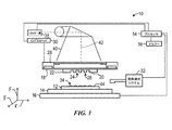
図面、特に図1を参照する。これは、基板12上にレリーフパターンを形成するために使用されるリソグラフィーシステム10を示す。基板12は基板チャック14につながれていてもよい。図示するように、基板チャック14は真空チャックである。しかし、基板チャック14は、真空、ピンタイプ、溝タイプ、静電気、電磁気及び/又は同様なもののいずれのチャックであってもよい(これらに限定されない)。例示的なチャックが、米国特許第6873087号公報に記載されている。
Reference is made to the drawings, particularly FIG. This shows the
基板12及び基板チャック14は、ステージ16によってさらに支持されていてもよい。ステージ16は、x、y及びz軸に沿った平行移動及び/又は回転運動を提供してもよい。ステージ16、基板12及び基板チャック14も基礎(図示せず)上に置かれていてもよい。
The
基板12から離れた位置にテンプレート18がある。テンプレート18は、第1の側面及び第2の側面を有する本体を有しており、一方の側面は、基板12の方へ延びるメサ20を有する。メサ20は、その上にパターニング表面22を有する。また、メサ20は型20とも呼ばれる。あるいは、テンプレート18は、メサ20なしで形成されていてもよい。
There is a
テンプレート18及び/又は型20は、融解石英、石英、ケイ素、有機高分子、シロキサン重合体、ホウケイ酸ガラス、フッ化炭素高分子、金属、硬化サファイア、及び/又は同様なもの(これらに限定されない)の材料から形成されていてもよい。図示したように、パターニング表面22は、複数の離間する凹部24及び/又は突出26によって定められるフィーチャーを有する。ただし、本発明の実施形態は、かかる構成(例、平坦な表面)に限定されない。パターニング表面22は、基板12上に形成されるパターンの基礎を形成するあらゆるオリジナルのパターンを定めてもよい。
テンプレート18はチャック28につながっていてもよい。チャック28は、真空、ピンタイプ、溝タイプ、静電気、電磁気、及び/又は他の同様なチャックのタイプとして構成される(これらに限定されない)。例示的なチャックは、米国特許第6873087号公報にさらに記載されている。また、チャック28及び/又はインプリントヘッド30がテンプレート18の移動を促進するように構成されるように、チャック28はインプリントヘッド30につながっていてもよい。
The
システム10は、流体提供システム32をさらに有していてもよい。流体提供システム32は、基板12上に成形性材料34(例、重合性材料)を堆積させるために使用されていてもよい。成形性材料34は、落下提供、スピンコーティング、浸漬コーティング、化学蒸着(CVD)、物理蒸着(PVD)、薄膜堆積、厚膜堆積、及び/又は同様なもののような技術を用いて基板12に配置させてもよい。成形性材料34は、設計上の考慮事項に依存して、所望の体積が型22と基板12の間に定められる前に及び/又は後に、基板12上に配置されてもよい。成形性材料34は、バイオ領域、太陽電池産業、電池産業、及び/又は機能的なナノ粒子を必要とする他の産業において用いられている機能的なナノ粒子とすることができる。例えば、成形性材料34は、米国特許第7157036号公報及び米国特許出願第2005/0187339号公報に記載されているようなモノマー混合物を含んでいてもよい。あるいは、成形性材料34は、バイオ素材(例、PEG)、太陽電池材料(例、N型、P型の材料)、及び/又は同様なものを含んでいてもよい(これらに限定されない)。
The
図1及び2を参照する。システム10は、パス42に沿ってエネルギー40を向かわせるためにつながれたエネルギー源38をさらに有していてもよい。インプリントヘッド30及びステージ16は、テンプレート18及び基板12をパス42に重複するように配置するように構成されていてもよい。システム10は、ステージ16、インプリントヘッド30、流体提供システム32及び/又は線源38との通信にてプロセッサー54によって統制されていてもよく、メモリー56に格納されたコンピューターが読取り可能なプログラムで動作してもよい。
Reference is made to FIGS.
インプリントヘッド30とステージ16の一方又は両方は、型20と基板12の間の距離を変え、これによって、成形性材料34によって充填される型20と基板12の間の所望の空間が定められる。例えば、型20が成形性材料34と接触するように、インプリントヘッド30がテンプレート18に力を加えてもよい。所望の体積が成形性材料34で充填された後、線源38はエネルギー40(例、紫外線)を発生させる。その結果、成形性材料34が固体化及び/又は架橋して、基板12の表面44及びパターニング表面22の形と同じになり、基板12上のパターン化層46を定める。パターン化層46は、残余の層48と、及び突出50及び凹部52として示されている複数のフィーチャーとを含んでいてもよく、突出50が厚みt1を有し、残余の層が厚みt2を有する。
One or both of the imprint head 30 and the
前記システム及びプロセスは、米国特許第6932934号公報、米国特許第7077992号公報、米国特許第7179396号公報、及び米国特許第7396475号公報に記載のインプリントリソグラフィープロセス及びシステムでさらに用いられている。 The systems and processes are further used in the imprint lithography processes and systems described in US Pat. No. 6,932,934, US Pat. No. 7,077,992, US Pat. No. 7,179,396, and US Pat. No. 7,396,475.
他のアプリケーションにおいても、ワイヤーグリッド偏光器(WGP)のような光学デバイスの製造において、インプリントリソグラフィープロセス及びシステムを有利に使用することができる。ワイヤーグリッド偏光器は、様々な産業及び市場で使用される、光学デバイスを含む様々なデバイスにおいて使用することができる。一例は、液晶ディスプレー(LCD)のフラットパネルモジュールにWGPを組み入れることである。これらのフラットパネルモジュールは、モバイルデバイス(例、電話、タブレット、ノートブックコンピューター)、コンピューターモニター、テレビ等のデバイスのための表示画面の製造に適用することができる。 In other applications, imprint lithography processes and systems can be advantageously used in the manufacture of optical devices such as wire grid polarizers (WGP). Wire grid polarizers can be used in a variety of devices, including optical devices, used in a variety of industries and markets. One example is the incorporation of WGP in a liquid crystal display (LCD) flat panel module. These flat panel modules can be applied to the manufacture of display screens for devices such as mobile devices (eg, phones, tablets, notebook computers), computer monitors, televisions and the like.
今まで、WGPは、プロジェクターのような小さな市場に制限されてきた。その理由は、高い製造コストに加え、WGPを大面積にスケーリングする際の困難さにある。本明細書にて記載される方法を使用して大きなマスターテンプレートを作成し、その後でさらにインプリントリソグラフィーのような別の技術を使用することによって、WGP技術を、より主流となっている大面積表示アプリケーションに利用することが可能になる。マスターマスクとインプリントリソグラフィーを組み合わせることによって、ディスプレーの性能を改善し、ディスプレーの電力消費を低下させて電池寿命を延ばす、コスト効率の良い解決策が可能になる。 To date, WGP has been limited to small markets such as projectors. This is because of the difficulty in scaling WGP to large areas in addition to high manufacturing costs. By using the method described herein to create a large master template, and then using another technique such as imprint lithography, the WGP technology is becoming more mainstream. It can be used for display applications. Combining the master mask and imprint lithography enables a cost-effective solution that improves display performance, lowers display power consumption, and extends battery life.
しかし、前述のように、本発明はWGPに限定されない。記載したアプローチによって、他の大面積パターンを作ることができ、これは、マスターテンプレートの形成に有用となることがある。例えば、大面積ドットアレー、ホールアレー等は、太陽のデバイス、波長シフト等に有用なプラズモン的なふるまいを可能にすることができる。 However, as described above, the present invention is not limited to WGP. The approach described can produce other large area patterns, which can be useful in the formation of master templates. For example, large area dot arrays, hole arrays, etc. can enable plasmonic behavior useful for solar devices, wavelength shifts, and the like.
大面積WGPを作る以前の取り組みは部分的に成功したが、隣接フィールドのインタフェースにおいて望ましくない欠損部ないしシームをもたらした。ステッパー又はスキャナーによって、グレーティングの適切な解像度を備えたマスターマスクを定め、その後に、ステップアンドリピートアプローチを用いて、はるかに大きな面積を有するレプリカテンプレート(複製テンプレート)、すなわち、ワーキングテンプレートを作ることができる。すなわち、マスターの小さなフィールドパターンが何度もプリントされ、より大きな面積の繰り返しパターンを作る。しかし、2つのフィールドが互いに隣接して配置される場合に欠損部が生じる場合がある。商業的に適切な大面積WGPは、見る人にとって認識可能な視覚上の欠陥を偏光器が有していないことを必要とする。大面積表示アプリケーションでは、目はパターン中の1μm未満の欠損部を感じることができる。例えば、2×2のフィールドアレーを有する25mm×25mmのパターンの繰り返しにより形成されたWGPである。このデバイスは25mm×25mm以内のフィールドで良好な性能を発揮するが、フィールドはお互い数十μm分離され、お互いシームレスには隣接しない。このように、約1μm以上の接合部のエラーについて、欠損部の問題は存在する。 Previous efforts to create large area WGPs have been partially successful, but have resulted in undesirable defects or seams at adjacent field interfaces. A master mask with the appropriate resolution of the grating can be defined by a stepper or scanner, and then a replica template with a much larger area (replicating template), ie a working template, can be created using a step-and-repeat approach it can. That is, a small master field pattern is printed many times to create a repeating pattern with a larger area. However, a missing part may occur when two fields are arranged adjacent to each other. Commercially appropriate large area WGP requires that the polarizer does not have a visual defect that is perceptible to the viewer. In a large area display application, the eyes can feel a defect of less than 1 μm in the pattern. For example, a WGP formed by repeating a pattern of 25 mm × 25 mm having a 2 × 2 field array. This device performs well in a field within 25 mm × 25 mm, but the fields are separated from each other by several tens of μm and are not seamlessly adjacent to each other. As described above, there is a problem of a defective portion with respect to an error of a joint portion of about 1 μm or more.
インプリントリソグラフィーを使用するいくつかのアプリケーションでは、大面積(〜>30mm×30mm)をカバーしなければならない小さな寸法(200nm未満)のパターンを必要とする。より小さなフィールド(面積)においては、小さなフィーチャーのパターン化のために電子ビーム書き込みシステム(e-beam writing system)が許容範囲内であることがある。大面積においては、電子ビームシステムの書き込み時間は許容できないほどに遅い。コンタクト型/近接型のアライナー、ホログラフィープロジェクターのような他のリソグラフィーシステムは、大きなパネルを有するステッパーであり、スキャナーが相当に大きな面積をカバーすることができても必要な解像度がない。 Some applications using imprint lithography require patterns with small dimensions (less than 200 nm) that must cover a large area (~> 30 mm × 30 mm). In smaller fields, the e-beam writing system may be acceptable for patterning small features. In large areas, the writing time of electron beam systems is unacceptably slow. Other lithography systems, such as contact / proximity aligners and holographic projectors, are steppers with large panels and do not have the necessary resolution even though the scanner can cover a fairly large area.
インプリントリソグラフィープロセスによってこのような大面積WGPを製造するためには、対応する寸法を有するマスターテンプレートの製造を必要とする。これらのタイプのマスターテンプレートは、大面積WGPだけでなく、性能が大面積すべてにわたって一定でなければならない平均化デバイスの生成に本質的に依存する他の大面積光学デバイスをもインプリントするのに有用である。本明細書では、フィールド間で「シームレス」のように見えるパターンを有するウェハー基板上に大面積インプリントテンプレートを作る方法が提供される。このような方法には、ステッパー又はスキャナー及び/又はインプリントリソグラフィープロセス及びツールの使用を伴う。特定の実施形態において、隣接し合うフィールドが「シームレス」にプリントすることを確実にするために、光学近接効果の戦略及びフィールドオフセットの戦略が用いられる。本明細書において提供される方法を使用して、ステッピングフィールド間にシームがほとんどないかまったくないように、大面積パターンを作ることができる。このようなパターンは、本明細書で提供される方法を用いることの他、ハイエンドの光ステッパー及びスキャナーのステージ精度の有利さを享受して、理想的な配置の10nm以下の範囲内にフィールドを配置することによって作ることができる。193nmの浸漬スキャナー(immersion scanner)のような、今日のハイエンドの光リダクションステッパー及びスキャナーツールは、40nmもの小さなフィーチャーを解像することができ、10nm未満のステージ精度を有する。本明細書で提供される方法を用いることの他、パターン拡大にまつわる問題をいずれも考慮することによって、300mmウェハー上にほぼシームレスな大面積パターンを作ることが可能である。 In order to manufacture such a large area WGP by an imprint lithography process, it is necessary to manufacture a master template having corresponding dimensions. These types of master templates not only imprint large area WGP, but also other large area optical devices that rely essentially on the generation of averaging devices whose performance must be constant across all large areas. Useful. Provided herein is a method of making a large area imprint template on a wafer substrate having a pattern that appears to be “seamless” between fields. Such methods involve the use of steppers or scanners and / or imprint lithography processes and tools. In certain embodiments, an optical proximity effect strategy and a field offset strategy are used to ensure that adjacent fields print “seamlessly”. Using the methods provided herein, large area patterns can be created such that there is little or no seam between stepping fields. Such a pattern takes advantage of the stage accuracy of high-end optical steppers and scanners, in addition to using the methods provided herein, to provide a field within 10 nm of ideal placement. Can be made by placing. Today's high-end optical reduction steppers and scanner tools, such as 193 nm immersion scanners, can resolve features as small as 40 nm and have stage accuracy of less than 10 nm. In addition to using the methods provided herein, it is possible to create a nearly seamless large area pattern on a 300 mm wafer by considering all the problems associated with pattern expansion.
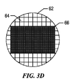
図3A〜3Dに移る。ここでは、300mmウェハー上の大面積にわたってシームレスなパターンを形成する本発明の一実施形態に従う各ステップを示してある。図3Aは、パターンがないウェハー62を示す。図3Bは、ウェハー62上の個々のステッパー又はスキャナーのフィールド64のプリントの開始時を示す。図3Cは、フィールド64で完全に占められたウェハー62を示す。図3Dは、300mmウェハー(約11.6インチ)で作ることができる最大の16:9比の大面積パターン166を示す。なお、450mmウェハーへ移行することが今後ありうるので、このプロセスによってさらに大きい面積パターン(及びこれによって発生するマスクやテンプレート)を定めることができるであろう。
Turning to FIGS. Here, the steps according to one embodiment of the present invention for forming a seamless pattern over a large area on a 300 mm wafer are shown. FIG. 3A shows a
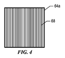
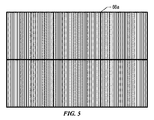
例示的なアプリケーションにおいて、ワイヤーグリッド偏光器(WGP)を形成するために、図4に示すように、ステッパー又はスキャナーのフィールド64aを、一連の平行線68を有するように構成することができる。これらは、線形のグレーティングパターンを発生させることができる。本明細書にさらに記載するように、このパターン化されたフィールドは、シームレスに「接合」して、より大きな面積のグレーティング66aを作ることができる。なお、193nmのスキャナーで今日作ることができる最も小さなハーフピッチのフィーチャーは、約40nmであるが、このことは、本明細書に記載された方法に従って形成されたパターン化されたフィーチャーの限界を定めないことを理解できるであろう。例えば、堆積及びエッチバックの工程を伴う技術である、スペーサーダブルパターニング技術を使用して、20nmへとピッチを半分にすることができる。3倍又は4倍のスペーサーパターニングによって、さらに小さな寸法を実現することができる。WGPにおいては、50nmのハーフピッチによって十分な性能を与えることができる。
In an exemplary application, to form a wire grid polarizer (WGP), a stepper or
また、本明細書に記載された方法が線とスペースのパターンに限定されないことも理解できるであろう。例えば、ドット又は孔パターンを作るためにスキャナーも使用することができる。また、様々な長さ及び幅を有する組織された線分を必要とするパターンに対して同じプロセスを適用することができる。一例として、大面積の長方形アレーが約20nm×50nmの寸法を必要とする場合、20nmハーフピッチの線及びスペースをハードマスクに作るために、スペーサーダブルパターニング技術を用いることができる。そして、20nmの線と直角に50nmの線をパターン化することができる。一旦ハードマスクへとエッチングされれば、一連の20nm×50nmの線分が形成される。 It will also be appreciated that the methods described herein are not limited to line and space patterns. For example, a scanner can also be used to create a dot or hole pattern. The same process can also be applied to patterns that require organized line segments with varying lengths and widths. As an example, if a large area rectangular array requires dimensions of about 20 nm × 50 nm, a spacer double patterning technique can be used to create 20 nm half pitch lines and spaces in the hard mask. A 50 nm line can then be patterned perpendicular to the 20 nm line. Once etched into the hard mask, a series of 20 nm × 50 nm line segments are formed.
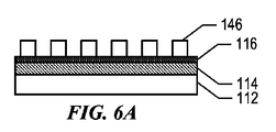
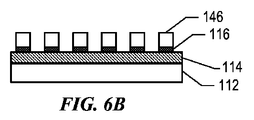
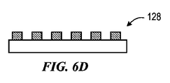
上記によって、ウェハー等の上にマスターマスク(又はテンプレート)を作るための大面積パターニングについて大まかに解決したが、付加的な加工ステップが必要である。図6A〜6Dは、このような例の1つを示す。図示するように、技術(熱酸化、CVD、PECVD、スパッタリング)をいくらか使用して、シリコンウェハー又は基板112上に、二酸化ケイ素膜114が堆積される。レジストパターン146を酸化物層114上に形成することができる。代わりに、図6Aに示すように、まず、抗反射(AR)コーティング又は膜116を酸化物層114上に形成する。これは、AR膜116上にレジストパターン146を形成する前である。このようにして、AR膜116がレジストと酸化物の間に存在する。マスターテンプレートを作るために、まず、レジストパターン146がAR膜116に転写され(図6Bに示したように)、その後で、酸化物層114上に転写され(図6Cに示したように)、シリコン基板112上で止まる。残ったレジスト(及び存在すれば残ったAR膜も)が少しでもあれば、剥がされ、最終的なパターン化マスク又はテンプレート128を形成する(図6D)。
Although the above has roughly solved large-area patterning for producing a master mask (or template) on a wafer or the like, additional processing steps are required. Figures 6A-6D show one such example. As shown, a
シームレス又はほぼシームレスなパターンを作るためにフィールドをお互い結合することができる方法がいくつかある。例えば、フィールドサイズをセットするために、スキャナー又はステッパーの開口ブレードを使用することができる。ブレードからの軽度のフレアー(flair)によって、パターンの縁部分における照射量がばらつく。これを修正する1つの方法は、パターンの究極の縁部分においてフィーチャーの照射量を減少させることである。 There are several ways in which fields can be joined together to create a seamless or nearly seamless pattern. For example, a scanner or a stepper aperture blade can be used to set the field size. A slight flare from the blade will vary the dose at the edge of the pattern. One way to correct this is to reduce the dose of the feature at the ultimate edge of the pattern.
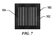
パターンを結合する第2の方法は、図7に示したマスク160のような暗視野マスクを使用する方法である。マスク160は、クロム化合物のような不透明な材料162を有し、これは、線164が定められる領域以外の全領域に堆積される。パターン領域外に位置する不透明な材料(例、クロム化合物)は、対象フィールドのリソグラフィー工程時に、いかなる迷光であっても隣接フィールドに当たることを防ぐ。
A second method for combining the patterns is to use a dark field mask such as
ワイヤーグリッド偏光器は、フラットパネルディスプレー及びスマートウィンドウを含む多様な市場に適用することができる。これらの技術には、視覚上の欠陥のない大面積用偏光器を必要とする。偏光器をインプリントするために必要とされるマスターテンプレートを製造する最も適当な方法として、大面積用偏光器を作るためにより小さなフィールドの偏光器が何度もプリントされる「ステップアンドリピート」の戦略を採用するものがある。本発明では、隣接フィールドが「シームレス」にプリントされることを確実にするために光学近接効果の戦略及びフィールドオフセットの戦略を採用する。 Wire grid polarizers can be applied to a variety of markets including flat panel displays and smart windows. These techniques require large area polarizers that are free of visual defects. The most appropriate way to produce the master template needed to imprint a polarizer is a “step and repeat” where a smaller field polarizer is printed many times to make a large area polarizer. Some adopt a strategy. The present invention employs an optical proximity effect strategy and a field offset strategy to ensure that adjacent fields are printed “seamlessly”.
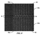
現在ハイエンドであるスキャナー及びステッパーツールは、10nmより良好な精度で隣接フィールドを配置することができるが、xとyの両方の方向におけるフィールドの縁部分におけるフィーチャーのプリントは、露光系の物理的特性の結果である光学的作用の影響を大きく受ける(特に、300nm未満のフィーチャーサイズの場合)。図8は、試みの結果が、約65nmの寸法を有するグレーティング線68がプリントされた隣接フィールド64b及び64cを当てる試みの結果を示す。図8において、フィールド64b及び64cが正しく配置されているにもかかわらず、プリントされた線68はy方向にて間にギャップg1があって接合していない。小さな寸法だけ線を短くすることは、通常、線端短縮と呼ばれる。図8は、x方向における光学的作用の問題を示す。見ればわかるように、結果として得られる端の線69aの空間的な像は、グレーティングの内側線68とは異なる。具体的には、端の線69aは、さらに大きなギャップ線端短縮の作用を有し、これは内側線68よりも短く、端の線69aの間のギャップg2はさらに大きい。また、線69aは、内側線68よりも狭い。他の光学的作用によって、フィーチャーが小さく見えたり、完全に解像せずに見えるようなことをもたらす。
Current high-end scanner and stepper tools can place adjacent fields with better accuracy than 10 nm, but feature printing at the edge of the field in both x and y directions is a physical property of the exposure system. Are greatly affected by the optical effects resulting from the above (especially in the case of feature sizes less than 300 nm). FIG. 8 shows the result of an attempt to hit
上記光学的作用は、フィールドの境界におけるプリントされたフィーチャーのサイジングを修正するために光近接効果補正(OPC)を適用することによって克服することができる。光近接効果補正(OPC)は、当分野において既知のリソグラフィー拡張技術であり、回折等の光学的作用に起因する像エラーを補正するのに一般的に使用されている。具体的には、線幅狭まり及び/又は線端短縮のような不規則性に対して、イメージングに使用されるマスク上のパターンを変更することによって補正を行うことが特に適している。OPCによってこれらのエラーを修正することができる。例えば、マスクに書き込まれた線パターンに縁部分を移動させる。これは、線フィーチャー(ルールベースのOPCとして知られる)間の幅及びスペーシングに基づいた、予め計算されたルックアップ表によって、又は最終パターンを動的にシミュレーションし、これによって、通常、区分に分けられた縁部分の移動を駆動させるようにコンパクトなモデルを用いることによって行われ、最良の解決策(モデルベースのOPC)がわかる。現在、OPC技術は、半導体デバイス用途に主として使用されている。しかし、このような技術は、フィールドの究極の端まで高い信頼性でプリントされたフィーチャーを必要とする状況では用いられていない。 The optical effects can be overcome by applying optical proximity correction (OPC) to modify the sizing of the printed features at the field boundaries. Optical proximity correction (OPC) is a lithographic extension technique known in the art and is commonly used to correct image errors due to optical effects such as diffraction. Specifically, it is particularly suitable to correct irregularities such as line width narrowing and / or line end shortening by changing the pattern on the mask used for imaging. These errors can be corrected by OPC. For example, the edge portion is moved to the line pattern written on the mask. This can be done with a pre-calculated look-up table based on the width and spacing between line features (known as rule-based OPC), or by dynamically simulating the final pattern, thereby usually partitioning This is done by using a compact model to drive the movement of the divided edge portions and the best solution (model-based OPC) is known. Currently, OPC technology is mainly used for semiconductor device applications. However, such techniques are not used in situations that require reliable printed features to the extreme edge of the field.
本発明において使用されるOPCは、4倍リダクションマスクから、マスク、テンプレート又はウェハー上のイメージングレジストへと転写される不完全な空間像を修正するために、4倍リダクションマスクに適用される必要のあるフィーチャー補正について記載する文脈において一般に使用される。例えば、本発明の一態様において、OPCは、隣接フィールドからのプリントされた線が「接合」又はさらに重複させるように、マスクの線(例、5〜200nmの範囲)を所望のプリント長さを超えて意図的に延長するために使用される。前述のように、WGPの場合には、フィーチャーはフィールドの究極の端にプリントする必要があり、OPC技術を適用することによって、境界におけるフィーチャーサイズを修正する、より正確な方法が提供される。例えば、プリントによって多数のフィールドを横切る連続的なシームレスな線を発生させることを確実にするために、境界の縁部分の近くの個々の線が修正されるような方法である。 The OPC used in the present invention needs to be applied to a 4x reduction mask to correct an incomplete aerial image transferred from the 4x reduction mask to an imaging resist on the mask, template or wafer. Commonly used in the context of describing certain feature corrections. For example, in one aspect of the present invention, the OPC reduces the mask line (eg, in the range of 5 to 200 nm) to the desired print length so that printed lines from adjacent fields are “joined” or further overlapped. Used to intentionally extend beyond. As previously mentioned, in the case of WGP, features need to be printed at the extreme edge of the field, and applying OPC technology provides a more accurate way to modify feature sizes at the boundaries. For example, in order to ensure that the print produces a continuous seamless line across multiple fields, the individual lines near the border edges are modified.
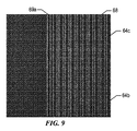
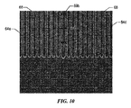
本発明の別の態様では、本質的にはプリントされたフィールドが重複するようにするために、フィールドの配置を意図的にオフセットするようにスキャナー又はステッパーをプログラムすることができる。図9は、フィールド64b及び64cが約80nmだけy方向に意図的にオフセットされる例を示す。見てわかるように、ギャップg1/g2がなくなっており、連続的なグレーティング線68及び69aを作っており、これによって、y方向で当たっているフィールドをもはや認識できなくなっている。しかし、このようなオフセットアプローチは、まだ光学的作用が作る狭まった端線を修正できていない。より狭い端線を修正するために、各フィールドはx方向にも同様に重複していてもよい。このことは、図10に示してある。ここに示した補正は、x方向への50nmのシフトを使用しており、これによって、フィールド64dと64eの間にx方向の重複を発生させている。これによって、以前の狭い端の線69aが重複することになり、線69bが得られる。描かれた線69bは線68に比べるとわずかに大きくなっているが、x方向にて端のフィーチャーの大きさを変えるように、重複をずらすこと及び/又はOPC技術の使用によって、結果として得られる幅をさらに調整することができる。OPC技術とフィールドオフセットの組合せを、所望のフィーチャー幅の連続的でシームレスなグレーティングを達成するために使用できることを理解できるであろう。
In another aspect of the invention, the scanner or stepper can be programmed to deliberately offset the field placement in order to essentially overlap the printed fields. FIG. 9 shows an example in which the
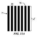
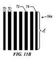
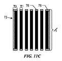
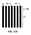
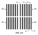
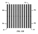
図11A〜11D及び12A〜12Bには、上記のOPC及び/又はオフセット補正の概要図を示す。図11Aは、幅w1×長さl1の同じ寸法の線70を有するマスク71を示す。上で議論した光学的作用に起因して、図11Bに示すように、マスク71は、線端短縮及び線狭幅化の影響を受けたフィールド84aをプリントする。具体的には、内側線72及び端の線74はすべて長さl2まで短縮しており、端の線74は幅w2までさらに狭くなっている。図11Cはマスク73を示す。これは、同じ幅w1の内側線76を有するが長さl3まで伸長され、端の線78は両方ともに長さl3まで伸長され幅w3までさらに広げられている。マスク73は、すべての線80が同じ所望の長さl1及び幅w1を有するフィールド88aをプリントする。図12Aには、マスク71を用いて隣接フィールド84a〜84dをプリントした結果を示してあり、これには、線短縮作用と、内側線72の幅と比較して狭まった端線74の幅とに起因してフィールド間に望まないギャップが発生している。対照的に、図12Bは、マスク73を用いて隣接フィールド84a〜84dをプリントした結果を示してあり、これにおいては、各々所望の長さ及び幅を有する線80の所望のシームレスなパターニングが得られている。なお、必要なx及びy方向のオフセットを行ったマスク71を使用して重複プリントすることによっても、図12Bの結果を得ることができる。また、OPCと重複を組み合わせて、図12Bの結果を同様に得ることができる。
11A to 11D and 12A to 12B are schematic views of the above OPC and / or offset correction. FIG. 11A shows a
なお、フィーチャーの大きさが小さくなると、上記光学的作用の問題が悪くなることには留意すべきである。図8〜10に示した例において、65nmのフィーチャー線がプリントされている。前述のように、65nmは、浸漬ベースの193nmのスキャナーを使用して解像するのがかなり簡単な数字である。しかし、ワイヤーグリッド偏光器は、より短い波長で最良な性能を発揮する。線幅50nmのWGPは、使用するために良い線サイズであるように思え、ハイエンドの浸漬スキャナーを使えば40nmも可能である。しかし、40nmでは、プリントプロセスのプロセス許容度はかなり小さい。また、空間像のいかなる欠陥があっても、隣接したグレーティングフィールドにとってより重大なプリント問題を引き起こし、これによって、上記アプローチをさらに頼ることになる。大面積パターンをシームレスに「接合」する別の方法として、アレー全体における一部を露光する際に、隣接するフィールドの縁部分どうしがいずれのリソグラフィー工程でも同時に露光されることがないようにいくつものリソグラフィー工程が行われるような、インプリントリソグラフィーを行う方法がある。図13A〜13Eは、このようなプロセスの一例を示す。図13Aに示すように、基板212に酸化物層214及びハードマスク層216が提供される。ハードマスク216上にレジストパターン層246aが形成される。図示するように、レジストパターン層246aは、パターンフィールドF1及びF3においてパターン化されたフィーチャー250aを含んでいる。一方、フィールドF2はパターン化されていないままである。露光の後、F1及びF3のパターンがハードマスク216(例、Cr、高分子、窒化物、カーボン、他の金属)へとエッチングされ、残ったレジスト146aが除去される(図13B)。その後、パターン化層146bがハードマスク216上に形成され、パターン化層146bがパターンフィールドF2にてパターン化されたフィーチャー250bを含み、フィールドF1及びF3はパターン化されたままである(図13C)。再び、露光の後、F2パターンがハードマスク216へとエッチングされ、残ったレジストが除去される(図13D)。フィールドすべてが埋まるまで(ハードマスク216へとパターン化されるまで)このプロセスをさらに繰り返すことができる。その後、酸化物層214へとパターンがエッチングされ、大面積のパターン化マスク228が作られる。この「Litho/Etch-Litho/Etch」(又はLELE)アプローチのために位置合わせ(アライメント)が必要な場合、まず、ウェハーに対して、位置合わせマークをゼロレベルにセットする。例えば、このような位置合わせマークを有効領域の外に配置する。別の例では、まず、位置合わせマークを各フィールドに配置して、次に、ウェハーへとエッチングする。次に、平坦化ステップを用いて、いかなるトポグラフィーをも除去され、これによって、位置合わせマークによっていかなる望まれないパターンも除去される。
It should be noted that the smaller the feature size, the worse the above optical problem. In the example shown in FIGS. 8 to 10, a 65 nm feature line is printed. As mentioned above, 65 nm is a fairly simple number to resolve using an immersion based 193 nm scanner. However, wire grid polarizers perform best at shorter wavelengths. A WGP with a line width of 50 nm seems to be a good line size to use, and 40 nm is possible with a high-end immersion scanner. However, at 40 nm, the process tolerance of the printing process is quite small. Also, any defect in the aerial image causes a more serious printing problem for the adjacent grating field, which further relies on the above approach. Several other ways to seamlessly “join” large area patterns so that when exposing portions of the entire array, the edges of adjacent fields are not exposed at the same time in any lithography process There is a method for performing imprint lithography in which a lithography process is performed. Figures 13A-13E illustrate an example of such a process. As shown in FIG. 13A, an
本明細書に記載される方法に従って形成されたマスターマスクがメサを有して、パターンがシリコンの高くなった部分の上に存在することが望ましい場合がある。このようなメサは、例えば、図14A〜14Eに示した方法に従って形成することができる。図14Aは、シリコン基板312と、及びパターン化されたフィーチャー350を有する酸化物層314を示す。ここで、パターン化されたフィーチャー350は酸化物層314に形成されている。一層のリソグラフィー工程は、レジスト層346を設け、さらに随意に、酸化物のようなハードマスク層(図示せず)を設けることによってパターンフィーチャー350が保護されて、酸化物層314がパターンフィーチャー領域の外で露光される(図14B)。パターン(図14C)の外の領域を選択的にエッチングして取り除くために酸化物エッチングを行い、その後にシリコンエッチングを行い、これによって、基板312上にメサ360を形成する(図14D)。その後、残ったレジスト346が除去され、メサ360から延びるパターンフィーチャーを有するテンプレート328が提供される。酸化物とシリコンをエッチングするために多くの化学物質を用いることができる。酸化物に対しては、例えば、CF4やCHF3を用いる。シリコンに対しては、塩素や臭化水素を用いることができる。
It may be desirable for a master mask formed in accordance with the methods described herein to have mesas and a pattern to be present on the raised portion of silicon. Such a mesa can be formed, for example, according to the method shown in FIGS. FIG. 14A shows a
なお、本明細書に記載されたプロセスを使用する大面積マスターマスクやテンプレートの製造は、193nmの浸漬ツールの使用には特に限定されないことが理解されるだろう。例えば、極紫外リソグラフィー(EUV)ツールやナノインプリントリソグラフィー(NIL)ツールを使用することができる。また、走査ビーム干渉リソグラフィー(SBIL)、多重電子ビームリソグラフィー、及びステンシルベースの走査電子ビームリソグラフィーのような他のアプローチも、本明細書に記載された方法に従う大面積マスターやワーキングテンプレートの製造に用いることができる。 It will be appreciated that the fabrication of large area master masks and templates using the process described herein is not particularly limited to the use of a 193 nm immersion tool. For example, an extreme ultraviolet lithography (EUV) tool or a nanoimprint lithography (NIL) tool can be used. Other approaches such as scanning beam interference lithography (SBIL), multiple electron beam lithography, and stencil-based scanning electron beam lithography are also used to manufacture large area masters and working templates in accordance with the methods described herein. be able to.
大面積マスターマスクが作成されれば、インプリントリソグラフィーを使用してサブマスターテンプレート又はレプリカテンプレート(すなわち、ワーキングテンプレート)を形成するために、さらに別の方法を利用可能である。例えば、シリコンウェハーパターンをガラス基板に転写することができる。同様に、シリコンウェハーパターンをフレキシブル膜に転写することができる。フレキシブル膜上のパターンはレプリカテンプレートになり、これは、ロールツーロール(roll-to-roll)又はロールツープレート(roll-to-plate)システムにおいて使用することができる。 Once a large area master mask is created, yet another method can be used to form a sub-master template or replica template (ie, working template) using imprint lithography. For example, a silicon wafer pattern can be transferred to a glass substrate. Similarly, a silicon wafer pattern can be transferred to a flexible film. The pattern on the flexible membrane becomes a replica template, which can be used in a roll-to-roll or roll-to-plate system.
最後に、このような転写プロセスは、複数のステップアンドリピート(step-and-repeat)のインプリントを取り入れて、大面積レプリカマスクを埋めることができる。これは、パネルが3m×3mよりも大きい寸法を有するようなディスプレー用途において必要とされることがある。 Finally, such a transfer process can incorporate multiple step-and-repeat imprints to fill large area replica masks. This may be required in display applications where the panel has dimensions greater than 3m x 3m.
当業者であれば、本説明を読むことによって、様々な態様のさらなる別の変更例及び代替実施形態が明白になるであろう。したがって、本説明は例示的にすぎない。なお、本明細書に示され記載された形態は、実施例として解釈されるべきである。本明細書や図面に記載されたり図示された要素と材料は、置き換わってもよく、部分やプロセスは逆にされていてもよく、特定の特徴を独立して利用してもよい。これらはすべて、本説明がもたらす利益を考慮すると当業者には明白であろう。本発明の精神及び請求の範囲に記載される範囲から逸脱せずに、本明細書に記載された要素に対して変更を行うことができる。 Those skilled in the art will appreciate still other modifications and alternative embodiments of the various aspects upon reading this description. Accordingly, this description is merely exemplary. In addition, the form shown and described in this specification should be construed as an example. The elements and materials described or illustrated in this specification and the drawings may be interchanged, parts and processes may be reversed, and certain features may be utilized independently. All of these will be apparent to one of ordinary skill in the art in view of the benefits provided by this description. Changes may be made in the elements described herein without departing from the spirit of the invention and the scope described in the claims.
Claims (7)
前記基板上に複数のパターン化されたフィールドを作ることによって、前記基板上に所望の長さ及び幅のグレーティングを有するパターン化層を形成するステップとを含み、
前記複数のパターン化されたフィールドを作ることは、光学リソグラフィーステップによって各フィールドを作るために、10nm未満のフィールド配置精度の光学スキャナーと、暗視野マスクを使用するステップを更に含み、
前記暗視野マスクは、光学的作用を修正するために、所望の長さ及び幅より大きい長さおよび幅を有する1つ以上のグレーティングを更に含み、隣接するフィールドパターンのインタフェース上の欠損部が1μm未満であるように、1つ又は複数の前記パターン化されたフィールドは、光学的作用を修正するために、x及び/またはyの方向にオフセットされ、
前記基板上にパターン化されたフィーチャー領域を形成するために、前記基板にパターンを転写し、残ったパターン化層のいずれも除去するステップとを備えることを特徴とするインプリントリソグラフィーテンプレートを形成する方法。 Providing a substrate;
Forming a patterned layer having a desired length and width grating on the substrate by creating a plurality of patterned fields on the substrate; and
Creating the plurality of patterned fields further comprises using an optical scanner with a field placement accuracy of less than 10 nm and a dark field mask to create each field by an optical lithography step;
The dark field mask further includes one or more gratings having a length and width greater than the desired length and width to modify the optical effect, and a defect on the interface of the adjacent field pattern is 1 μm. one or more of the patterned fields is offset in the x and / or y direction to modify the optical effect so that it is less than m;
Forming an imprint lithography template comprising: transferring a pattern to the substrate and removing any remaining patterned layer to form a patterned feature region on the substrate; Method.
前記パターンは前記酸化物層へ転写されることを特徴とする請求項1に記載の方法。 The substrate has an oxide layer;
The method of claim 1, wherein the pattern is transferred to the oxide layer.
Applications Claiming Priority (3)
| Application Number | Priority Date | Filing Date | Title |
|---|---|---|---|
| US201161577135P | 2011-12-19 | 2011-12-19 | |
| US61/577,135 | 2011-12-19 | ||
| PCT/US2012/070639 WO2013096459A1 (en) | 2011-12-19 | 2012-12-19 | Fabrication of seamless large area master templates for imprint lithography |
Publications (3)
| Publication Number | Publication Date |
|---|---|
| JP2015502668A JP2015502668A (en) | 2015-01-22 |
| JP2015502668A5 JP2015502668A5 (en) | 2016-02-12 |
| JP6324318B2 true JP6324318B2 (en) | 2018-05-16 |
Family
ID=48609072
Family Applications (1)
| Application Number | Title | Priority Date | Filing Date |
|---|---|---|---|
| JP2014547570A Active JP6324318B2 (en) | 2011-12-19 | 2012-12-19 | Method for producing a seamless large area master template for imprint lithography |
Country Status (7)
| Country | Link |
|---|---|
| US (1) | US9452574B2 (en) |
| JP (1) | JP6324318B2 (en) |
| KR (2) | KR102149669B1 (en) |
| CN (2) | CN107015433B (en) |
| SG (2) | SG10201608504SA (en) |
| TW (1) | TWI570771B (en) |
| WO (1) | WO2013096459A1 (en) |
Families Citing this family (34)
| Publication number | Priority date | Publication date | Assignee | Title |
|---|---|---|---|---|
| WO2015060943A1 (en) * | 2013-10-24 | 2015-04-30 | Moxtek, Inc. | Polarizer with variable inter-wire distance |
| US9632223B2 (en) | 2013-10-24 | 2017-04-25 | Moxtek, Inc. | Wire grid polarizer with side region |
| CN103576221B (en) * | 2013-10-25 | 2015-11-18 | 中国科学院半导体研究所 | A kind of electron beam exposure method improving optical grating construction uniformity coefficient |
| KR102214830B1 (en) | 2014-05-02 | 2021-02-10 | 삼성전자주식회사 | Manufacturing method of Master mold |
| KR102219703B1 (en) | 2014-05-07 | 2021-02-24 | 삼성전자주식회사 | Patterning method using imprint and pattern structure fabricated by the method, and imprinting system |
| KR102176591B1 (en) | 2014-05-07 | 2020-11-09 | 삼성전자주식회사 | Wire grid polarizer, liquid crystal display having the same and method of manufacturing the same |
| KR102336499B1 (en) * | 2014-08-04 | 2021-12-07 | 삼성전자주식회사 | Pattern structure and method of manufacturing the pattern structure, and liquid crystal display device having metal wire grid polarizer |
| KR102332038B1 (en) | 2015-04-10 | 2021-11-30 | 삼성디스플레이 주식회사 | Imprint lithography method, method for manufacturing master template using the method and master template manufactured by the method |
| KR102306655B1 (en) | 2015-04-10 | 2021-09-29 | 삼성디스플레이 주식회사 | Liquid crystal display and method for manufacturing the same |
| US9989845B2 (en) | 2015-04-16 | 2018-06-05 | Samsung Display Co., Ltd. | Imprint lithography method, method for manufacturing master template using the method and master template manufactured by the method |
| KR102446872B1 (en) | 2015-04-24 | 2022-09-26 | 삼성디스플레이 주식회사 | display panel |
| KR20170091439A (en) * | 2016-02-01 | 2017-08-09 | 삼성전자주식회사 | Pattern structure and method of manufacturing the same |
| WO2017151291A1 (en) * | 2016-03-04 | 2017-09-08 | Applied Materials, Inc. | Wire grid polarizer manufacturing method |
| WO2017156388A1 (en) * | 2016-03-11 | 2017-09-14 | Inpria Corporation | Pre-patterned lithography templates, processes based on radiation patterning using the templates and processes to form the templates |
| CN105789118B (en) * | 2016-04-14 | 2019-03-22 | 京东方科技集团股份有限公司 | A display substrate and its manufacturing method |
| KR102526936B1 (en) * | 2016-04-26 | 2023-04-28 | 삼성디스플레이 주식회사 | Display panel and mother substrate for display panel |
| KR102535820B1 (en) | 2016-05-19 | 2023-05-24 | 삼성디스플레이 주식회사 | Imprint lithograhy method, substrate manufactured by the method, master template for imprint, wire grid polarizer manufactured using the master template and display substrate having the same |
| KR102607657B1 (en) | 2016-06-07 | 2023-11-28 | 티씨엘 차이나 스타 옵토일렉트로닉스 테크놀로지 컴퍼니 리미티드 | Method for forming fine pattern |
| KR20180023102A (en) | 2016-08-23 | 2018-03-07 | 삼성디스플레이 주식회사 | Wire grid pattern and method for fabricating the same |
| KR102697540B1 (en) | 2016-09-27 | 2024-08-23 | 삼성디스플레이 주식회사 | Method of manufacturing imprint master template |
| KR20180039228A (en) | 2016-10-07 | 2018-04-18 | 삼성디스플레이 주식회사 | Method of manufacturing display apparatus |
| KR20180044744A (en) | 2016-10-24 | 2018-05-03 | 삼성전자주식회사 | Pattern structure and method of manufacturing the pattern structure |
| KR20200003295A (en) * | 2017-05-16 | 2020-01-08 | 어플라이드 머티어리얼스, 인코포레이티드 | Wire grid polarizer manufacturing methods using frequency doubling interference lithography |
| TWI646389B (en) * | 2017-09-12 | 2019-01-01 | 友達光電股份有限公司 | Imprinting mold and manufacturing method of imprinting mold |
| US10948818B2 (en) * | 2018-03-19 | 2021-03-16 | Applied Materials, Inc. | Methods and apparatus for creating a large area imprint without a seam |
| US10705269B2 (en) * | 2018-03-30 | 2020-07-07 | Northrop Grumman Systems Corporation | Fabrication method of a diffractive optic for hybrid coherent and spectral beam combination |
| KR102666843B1 (en) | 2018-08-31 | 2024-05-21 | 삼성디스플레이 주식회사 | Master stamp for nano imprint and method of manufacturing of the smae |
| WO2020080372A1 (en) * | 2018-10-16 | 2020-04-23 | Scivax株式会社 | Fine pattern molding method, imprint mold manufacturing method, imprint mold, and optical device |
| CN113490883A (en) * | 2019-02-11 | 2021-10-08 | 应用材料公司 | Large area seamless master and imprint stamp manufacturing method |
| CN110824835B (en) * | 2019-11-26 | 2023-05-12 | 京东方科技集团股份有限公司 | Splicing nano-imprint template, method for repairing its splicing seam, and manufacturing method thereof |
| CN111522206B (en) * | 2020-04-29 | 2021-09-21 | 中国科学院光电技术研究所 | Micro-nano optical printing manufacturing method based on reflection type optical field enhancement |
| WO2022023040A1 (en) | 2020-07-31 | 2022-02-03 | Morphotonics Holding B.V. | Welding method for creating an upscaled master |
| CN115480442A (en) * | 2021-05-31 | 2022-12-16 | 联华电子股份有限公司 | Pattern disassembling method |
| KR102716442B1 (en) * | 2021-12-09 | 2024-10-14 | 한국기계연구원 | Large-area seamless master and manufacturing method |
Family Cites Families (50)
| Publication number | Priority date | Publication date | Assignee | Title |
|---|---|---|---|---|
| US5437946A (en) | 1994-03-03 | 1995-08-01 | Nikon Precision Inc. | Multiple reticle stitching for scanning exposure system |
| JPH09251954A (en) * | 1996-01-10 | 1997-09-22 | Nikon Corp | Semiconductor device, reticle, and projection exposure method |
| KR100283408B1 (en) * | 1998-01-21 | 2001-04-02 | 김영환 | Mask for semiconductor device |
| WO1999066370A1 (en) * | 1998-06-17 | 1999-12-23 | Nikon Corporation | Method for producing mask |
| US6225013B1 (en) | 1999-05-20 | 2001-05-01 | Tower Semiconductor Ltd. | Stitching design rules for forming interconnect layers |
| US6873087B1 (en) | 1999-10-29 | 2005-03-29 | Board Of Regents, The University Of Texas System | High precision orientation alignment and gap control stages for imprint lithography processes |
| US6387787B1 (en) | 2001-03-02 | 2002-05-14 | Motorola, Inc. | Lithographic template and method of formation and use |
| JP3985165B2 (en) * | 2001-08-20 | 2007-10-03 | 日産化学工業株式会社 | Antireflection film forming composition for lithography |
| US6849558B2 (en) * | 2002-05-22 | 2005-02-01 | The Board Of Trustees Of The Leland Stanford Junior University | Replication and transfer of microstructures and nanostructures |
| US7077992B2 (en) * | 2002-07-11 | 2006-07-18 | Molecular Imprints, Inc. | Step and repeat imprint lithography processes |
| US6932934B2 (en) | 2002-07-11 | 2005-08-23 | Molecular Imprints, Inc. | Formation of discontinuous films during an imprint lithography process |
| US6936194B2 (en) | 2002-09-05 | 2005-08-30 | Molecular Imprints, Inc. | Functional patterning material for imprint lithography processes |
| US20040121246A1 (en) * | 2002-09-20 | 2004-06-24 | Brown David R. | Lithography process to reduce seam lines in an array of microelements produced from a sub-mask and a sub-mask for use thereof |
| US20040065252A1 (en) | 2002-10-04 | 2004-04-08 | Sreenivasan Sidlgata V. | Method of forming a layer on a substrate to facilitate fabrication of metrology standards |
| US8349241B2 (en) | 2002-10-04 | 2013-01-08 | Molecular Imprints, Inc. | Method to arrange features on a substrate to replicate features having minimal dimensional variability |
| US7179396B2 (en) | 2003-03-25 | 2007-02-20 | Molecular Imprints, Inc. | Positive tone bi-layer imprint lithography method |
| US7396475B2 (en) | 2003-04-25 | 2008-07-08 | Molecular Imprints, Inc. | Method of forming stepped structures employing imprint lithography |
| US7157036B2 (en) | 2003-06-17 | 2007-01-02 | Molecular Imprints, Inc | Method to reduce adhesion between a conformable region and a pattern of a mold |
| US7003758B2 (en) * | 2003-10-07 | 2006-02-21 | Brion Technologies, Inc. | System and method for lithography simulation |
| US8076386B2 (en) | 2004-02-23 | 2011-12-13 | Molecular Imprints, Inc. | Materials for imprint lithography |
| KR20060080010A (en) * | 2005-01-04 | 2006-07-07 | 매그나칩 반도체 유한회사 | Fine Pattern Forming Method Using Imprint Lithography |
| JP2006210856A (en) * | 2005-01-31 | 2006-08-10 | Toshiba Corp | Exposure method and semiconductor device manufacturing method |
| US7718326B2 (en) | 2005-06-17 | 2010-05-18 | Vincent E Stenger | Seamless stitching of patterns formed by interference lithography |
| KR20080068821A (en) * | 2005-09-30 | 2008-07-24 | 퀄컴 엠이엠스 테크놀로지스, 인크. | MEMS devices and connections for those devices |
| JP2007171451A (en) * | 2005-12-21 | 2007-07-05 | Matsushita Electric Ind Co Ltd | Exposure method and plasma display panel |
| JP2007193243A (en) * | 2006-01-23 | 2007-08-02 | Sony Corp | Exposure mask, exposure method, exposure mask manufacturing method, three-dimensional device, and three-dimensional device manufacturing method |
| JP2008107720A (en) * | 2006-10-27 | 2008-05-08 | Enplas Corp | Polarizer and its manufacturing method |
| KR101270200B1 (en) * | 2006-10-30 | 2013-05-31 | 삼성디스플레이 주식회사 | Method of manufacturing a wire grid polarizer and liquid crystal display manufactured by the same |
| KR100863570B1 (en) * | 2006-12-19 | 2008-10-15 | 삼성전자주식회사 | Manufacturing Method of Wire Grid Polarizer |
| KR101563874B1 (en) * | 2007-02-07 | 2015-10-29 | 주식회사 에스앤에스텍 | Blank stamps and stamps for nanoimprint lithography |
| JP4996488B2 (en) * | 2007-03-08 | 2012-08-08 | 東芝機械株式会社 | Fine pattern forming method |
| KR20080105524A (en) * | 2007-05-31 | 2008-12-04 | 삼성전자주식회사 | Mask mold, its manufacturing method and large area fine pattern molding method using the manufactured mask mold |
| JP5473266B2 (en) | 2007-08-03 | 2014-04-16 | キヤノン株式会社 | Imprint method, substrate processing method, and semiconductor device manufacturing method by substrate processing method |
| US7785946B2 (en) * | 2007-09-25 | 2010-08-31 | Infineon Technologies Ag | Integrated circuits and methods of design and manufacture thereof |
| US7985941B2 (en) * | 2007-11-16 | 2011-07-26 | 3M Innovative Properties Company | Seamless laser ablated roll tooling |
| US8518633B2 (en) * | 2008-01-22 | 2013-08-27 | Rolith Inc. | Large area nanopatterning method and apparatus |
| WO2009093700A1 (en) * | 2008-01-25 | 2009-07-30 | Asahi Kasei Kabushiki Kaisha | Manufacturing method for seamless mold |
| JP2009210856A (en) * | 2008-03-05 | 2009-09-17 | Fujitsu Ltd | Hologram recording device |
| JP4799575B2 (en) * | 2008-03-06 | 2011-10-26 | 株式会社東芝 | Imprint method |
| JP5258635B2 (en) | 2008-03-18 | 2013-08-07 | キヤノン株式会社 | Nanoimprint method, mold used for nanoimprint, and method for producing structure |
| US20090246706A1 (en) * | 2008-04-01 | 2009-10-01 | Applied Materials, Inc. | Patterning resolution enhancement combining interference lithography and self-aligned double patterning techniques |
| US8192920B2 (en) * | 2008-04-26 | 2012-06-05 | Rolith Inc. | Lithography method |
| JP5370958B2 (en) * | 2008-09-25 | 2013-12-18 | 国立大学法人東京工業大学 | Nanoimprint mold |
| KR101880582B1 (en) * | 2008-12-05 | 2018-07-20 | 리퀴디아 테크놀로지스 인코포레이티드 | Method for producing patterned materials |
| JP4825891B2 (en) * | 2009-03-31 | 2011-11-30 | 株式会社東芝 | Semiconductor device manufacturing method and template |
| JP5377053B2 (en) * | 2009-04-17 | 2013-12-25 | 株式会社東芝 | Template, manufacturing method thereof, and pattern forming method |
| JP5257225B2 (en) * | 2009-04-28 | 2013-08-07 | 大日本印刷株式会社 | Nanoimprint mold and manufacturing method thereof |
| NL2005975A (en) * | 2010-03-03 | 2011-09-06 | Asml Netherlands Bv | Imprint lithography. |
| JP5619458B2 (en) * | 2010-03-31 | 2014-11-05 | Hoya株式会社 | Resist pattern forming method and mold manufacturing method |
| EP2609467A4 (en) * | 2010-08-23 | 2014-07-30 | Rolith Inc | Mask for near-field lithography and fabrication the same |
-
2012
- 2012-12-19 JP JP2014547570A patent/JP6324318B2/en active Active
- 2012-12-19 CN CN201710168787.6A patent/CN107015433B/en active Active
- 2012-12-19 CN CN201280062807.7A patent/CN104221127B/en active Active
- 2012-12-19 TW TW101148378A patent/TWI570771B/en active
- 2012-12-19 KR KR1020197033103A patent/KR102149669B1/en active Active
- 2012-12-19 US US13/720,315 patent/US9452574B2/en active Active
- 2012-12-19 SG SG10201608504SA patent/SG10201608504SA/en unknown
- 2012-12-19 KR KR1020147020172A patent/KR102044771B1/en active Active
- 2012-12-19 SG SG11201403060WA patent/SG11201403060WA/en unknown
- 2012-12-19 WO PCT/US2012/070639 patent/WO2013096459A1/en not_active Ceased
Also Published As
| Publication number | Publication date |
|---|---|
| TWI570771B (en) | 2017-02-11 |
| SG10201608504SA (en) | 2016-12-29 |
| CN107015433B (en) | 2021-06-04 |
| US9452574B2 (en) | 2016-09-27 |
| KR102044771B1 (en) | 2019-11-14 |
| KR20140117425A (en) | 2014-10-07 |
| CN107015433A (en) | 2017-08-04 |
| JP2015502668A (en) | 2015-01-22 |
| SG11201403060WA (en) | 2014-09-26 |
| WO2013096459A1 (en) | 2013-06-27 |
| US20130153534A1 (en) | 2013-06-20 |
| CN104221127A (en) | 2014-12-17 |
| KR102149669B1 (en) | 2020-09-01 |
| TW201335970A (en) | 2013-09-01 |
| CN104221127B (en) | 2017-04-12 |
| KR20190132695A (en) | 2019-11-28 |
Similar Documents
| Publication | Publication Date | Title |
|---|---|---|
| JP6324318B2 (en) | Method for producing a seamless large area master template for imprint lithography | |
| US7537866B2 (en) | Patterning a single integrated circuit layer using multiple masks and multiple masking layers | |
| JP5570688B2 (en) | Fine resist pattern forming method and nanoimprint mold structure | |
| US20080299467A1 (en) | Mask mold, manufacturing method thereof, and method for forming large-sized micro pattern using mask mold | |
| US20080292976A1 (en) | Pattern forming method, pattern formed thereby, mold, processing apparatus, and processing method | |
| US7560201B2 (en) | Patterning a single integrated circuit layer using multiple masks and multiple masking layers | |
| JP2011066238A (en) | Method of preparing pattern-forming template | |
| CN1351721A (en) | Method for error reduction in lithography | |
| US20130177840A1 (en) | Alignment marks for multi-exposure lithography | |
| JP4486364B2 (en) | All phase phase shift mask in damascene process | |
| TWI520857B (en) | Cliche and method for preparing the same | |
| JP2007027361A (en) | Imprint mold | |
| EP1839088A1 (en) | Imprint reference template for multilayer or multipattern registration and method therefor | |
| US20120135341A1 (en) | Method for double patterning lithography and photomask layout | |
| WO2023236254A1 (en) | Photomask pattern correction method, system, photomask and preparation method therefor | |
| JP6206644B2 (en) | Method for producing template for nanoimprint lithography | |
| JP5962353B2 (en) | Method for producing template for nanoimprint lithography | |
| JP6020026B2 (en) | Method for correcting defect in template for nanoimprint lithography, and method for manufacturing template for nanoimprint lithography | |
| TWI518444B (en) | Method of forming assist feature patterns | |
| TWI328255B (en) | Etching bias reduction | |
| CN115793413B (en) | Super-resolution pattern implementation method and device based on alignment difference and double lithography | |
| JP4774937B2 (en) | Template manufacturing method | |
| KR20120071794A (en) | High definition printing plate of liquid crystal display and method for manufacture using the same | |
| JP2019109499A (en) | Pattern drawing method, method for manufacturing photomask, photomask, and method for manufacturing display device | |
| CN116413995A (en) | Formation method of mask layout |
Legal Events
| Date | Code | Title | Description |
|---|---|---|---|
| A521 | Request for written amendment filed |
Free format text: JAPANESE INTERMEDIATE CODE: A523 Effective date: 20151215 |
|
| A621 | Written request for application examination |
Free format text: JAPANESE INTERMEDIATE CODE: A621 Effective date: 20151215 |
|
| A977 | Report on retrieval |
Free format text: JAPANESE INTERMEDIATE CODE: A971007 Effective date: 20160926 |
|
| A131 | Notification of reasons for refusal |
Free format text: JAPANESE INTERMEDIATE CODE: A131 Effective date: 20161004 |
|
| A601 | Written request for extension of time |
Free format text: JAPANESE INTERMEDIATE CODE: A601 Effective date: 20170104 |
|
| A601 | Written request for extension of time |
Free format text: JAPANESE INTERMEDIATE CODE: A601 Effective date: 20170306 |
|
| A521 | Request for written amendment filed |
Free format text: JAPANESE INTERMEDIATE CODE: A523 Effective date: 20170404 |
|
| A131 | Notification of reasons for refusal |
Free format text: JAPANESE INTERMEDIATE CODE: A131 Effective date: 20170718 |
|
| A601 | Written request for extension of time |
Free format text: JAPANESE INTERMEDIATE CODE: A601 Effective date: 20171018 |
|
| A521 | Request for written amendment filed |
Free format text: JAPANESE INTERMEDIATE CODE: A523 Effective date: 20171218 |
|
| TRDD | Decision of grant or rejection written | ||
| A01 | Written decision to grant a patent or to grant a registration (utility model) |
Free format text: JAPANESE INTERMEDIATE CODE: A01 Effective date: 20180320 |
|
| A61 | First payment of annual fees (during grant procedure) |
Free format text: JAPANESE INTERMEDIATE CODE: A61 Effective date: 20180410 |
|
| R150 | Certificate of patent or registration of utility model |
Ref document number: 6324318 Country of ref document: JP Free format text: JAPANESE INTERMEDIATE CODE: R150 |
|
| R250 | Receipt of annual fees |
Free format text: JAPANESE INTERMEDIATE CODE: R250 |
|
| R250 | Receipt of annual fees |
Free format text: JAPANESE INTERMEDIATE CODE: R250 |
|
| R250 | Receipt of annual fees |
Free format text: JAPANESE INTERMEDIATE CODE: R250 |
|
| R250 | Receipt of annual fees |
Free format text: JAPANESE INTERMEDIATE CODE: R250 |
|
| R250 | Receipt of annual fees |
Free format text: JAPANESE INTERMEDIATE CODE: R250 |
