JP6319967B2 - Sunshade assembly structure for vehicles - Google Patents
Sunshade assembly structure for vehicles Download PDFInfo
- Publication number
- JP6319967B2 JP6319967B2 JP2013164009A JP2013164009A JP6319967B2 JP 6319967 B2 JP6319967 B2 JP 6319967B2 JP 2013164009 A JP2013164009 A JP 2013164009A JP 2013164009 A JP2013164009 A JP 2013164009A JP 6319967 B2 JP6319967 B2 JP 6319967B2
- Authority
- JP
- Japan
- Prior art keywords
- sunshade
- door
- outer case
- door trim
- sunshade assembly
- Prior art date
- Legal status (The legal status is an assumption and is not a legal conclusion. Google has not performed a legal analysis and makes no representation as to the accuracy of the status listed.)
- Active
Links
- NJPPVKZQTLUDBO-UHFFFAOYSA-N novaluron Chemical compound C1=C(Cl)C(OC(F)(F)C(OC(F)(F)F)F)=CC=C1NC(=O)NC(=O)C1=C(F)C=CC=C1F NJPPVKZQTLUDBO-UHFFFAOYSA-N 0.000 claims description 11
- 210000000078 claw Anatomy 0.000 claims description 8
- 238000004804 winding Methods 0.000 description 8
- 208000027418 Wounds and injury Diseases 0.000 description 5
- 238000003466 welding Methods 0.000 description 4
- 230000006378 damage Effects 0.000 description 3
- 239000011521 glass Substances 0.000 description 3
- 208000014674 injury Diseases 0.000 description 3
- 239000002184 metal Substances 0.000 description 2
- 239000011347 resin Substances 0.000 description 2
- 229920005989 resin Polymers 0.000 description 2
- 238000012986 modification Methods 0.000 description 1
- 230000004048 modification Effects 0.000 description 1
Images


Landscapes
- Vehicle Interior And Exterior Ornaments, Soundproofing, And Insulation (AREA)
Description
本発明は、車両のサイドドアのウィンドウを遮光するためのサンシェードをサイドドアに取り付ける車両用サンシェードアッセンブリ構造に関するものである。 The present invention relates to a vehicle sunshade assembly structure in which a sunshade for shielding light from a side door window of a vehicle is attached to the side door.
一般に、車両のサイドドアのウィンドウを遮光するために、サイドドアにサンシェードを取り付けることが行われており、例えばシェードシートを巻き取る巻取手段がアウタケース内に収納されて、アウタケースがドアトリムの内側に取り付けられることにより、サンシェードがドアトリムの内側に配設される。そして従来、上記した巻取手段は、シャフトと、左右対を成すトーションスプリングと、スプリングカバーとから成り、このシャフトにシェードシートが巻き取られるようになっており、トーションスプリングの一端がシャフトの略中央部に係止されるとともに他端がアウタケースに係止され、トーションスプリングのコイル部が円筒状のスプリングカバーによって包被された状態で、スプリングカバーごと巻取手段がアウタケース内に収納され、該スプリングカバーの長尺方向に平行に形成されたスリットにシェードシートの一端部が止着されており、シェードシートの他端部に取り付けられたシェードフレームを把持してシェードシートを引っ張ることにより、シェードシートが巻取手段から展開され、このときシェードシートを展開するに連れてトーションスプリングのコイル部の捻じれ度合いが大きくなり、シェードシートを収納する際の巻き取り方向へのバネ力が蓄えられるようになっている(特許文献1参照)。 In general, a sunshade is attached to a side door in order to shield a window of a vehicle side door. For example, a winding means for winding a shade sheet is stored in the outer case, and the outer case is a door trim. By being attached to the inside, the sunshade is disposed inside the door trim. Conventionally, the winding means described above comprises a shaft, a torsion spring that forms a pair of left and right sides, and a spring cover. A shade sheet is wound around the shaft, and one end of the torsion spring is substantially the same as the shaft. The winding means is housed in the outer case together with the spring cover in a state where the other end is locked to the outer case and the coil portion of the torsion spring is covered with the cylindrical spring cover. One end portion of the shade sheet is fixed to a slit formed in parallel to the longitudinal direction of the spring cover, and the shade sheet attached to the other end portion of the shade sheet is gripped to pull the shade sheet. The shade sheet is unfolded from the winding means, and at this time, the shade sheet is unfolded. Take degree increases torsional a coil portion of the torsion spring by, so that the spring force in the winding direction at the time of housing the shade sheet is stored (see Patent Document 1).
しかし、上記した特許文献に記載のアウタケースは、ドアトリムの内側から車室内に向って複数個のビスが螺合されて取り付けられる構成であるため、他車両が側方から衝突したときに、ビスがドアトリムを突き破って車室内の乗員に怪我をさせるおそれがあり、安全性に問題がある。さらに、複数個のビスで止める構成であるため、コストがかかるという問題もある。また、ビスに代えて、樹脂製のボスとこれが挿通する孔との組み合わせで、ボスを溶着することでアウタケースを固着することも考えられるが、アウタケースを含むサンシェードアッセンブリに不具合が生じたときには、溶着する場合のようにサンシェードアッセンブリごと交換しなければならず、ユーザのコスト負担が大きくなりサービス性を欠くという不都合がある。 However, since the outer case described in the above-mentioned patent document has a structure in which a plurality of screws are screwed and attached from the inside of the door trim toward the vehicle interior, when the other vehicle collides from the side, May break through the door trim and cause injury to passengers in the passenger compartment, which is a safety issue. Furthermore, since it is the structure which stops with several screws, there also exists a problem that cost starts. In addition, instead of screws, it is possible to fix the outer case by welding the boss with a combination of a resin boss and a hole through which it is inserted, but when a problem occurs in the sunshade assembly including the outer case The sunshade assembly must be exchanged as in the case of welding, which increases the cost burden on the user and lacks serviceability.
本発明は、他車両の側方からの衝突が生じても乗員が怪我をすることを防止でき、安全性の向上を図るとともに、コストを低減できるようにすることを目的とする。 It is an object of the present invention to prevent an occupant from being injured even when a collision from the side of another vehicle occurs, to improve safety and to reduce costs.
上記した目的を達成するために、本発明の車両用サンシェードアッセンブリ構造は、車両のサイドドアの窓を遮光するためのサンシェードを前記サイドドアに取り付ける車両用サンシェードアッセンブリ構造において、前記サイドドアのドアトリムに車室内側に突出して設けられた台座部と、前記台座部の内側面に形成された係止孔と、断面し字状をなす長尺の基部と、該基部の下部に略垂直に形成された垂直部とを有し、前記基部の車室内に向かう端縁が前記ドアトリムに当接した状態で、前記サンシェードを展開・収納自在に保持するサンシェードアッセンブリが前記基部と前記ドアトリムとの間に収納されて、前記ドアトリムの内側に前記サンシェードアッセンブリを取り付けるアウタケースと、前記アウタケースの前記垂直部に設けられ前記係止孔に係止して前記アウタケースを前記ドアトリムに取り付ける係止爪とを備えることを特徴としている(請求項1)。 To achieve the above object, a vehicle sunshade assembly structure according to the present invention is a vehicle sunshade assembly structure in which a sunshade for shielding a window of a vehicle side door is attached to the side door. A pedestal portion protruding from the vehicle interior side, a locking hole formed in the inner surface of the pedestal portion, a long base having a cross-sectional shape, and a lower portion of the base are formed substantially perpendicularly. A sunshade assembly that holds the sunshade so that the sunshade can be unfolded and stowed is accommodated between the base and the door trim. is, an outer casing for attaching the sunshade assembly inside the door trim is provided on the vertical portion of the outer case It is characterized in that is provided with a locking pawl for attaching the outer casing engages with the locking hole in the door trim (claim 1).
請求項1に係る発明によれば、ドアトリムに車室内側に突出して設けられた台座部の内側面に形成された係止孔に、アウタケースの垂直部に設けられた係止爪を係止して、アウタケースをドアトリムに取り付けるため、他車両の側面衝突が生じたときには、ビス止めの場合のようにビスが突出することによる乗員の怪我が生じることを防止でき、アウタケースだけを簡単に取り外せるので、アウタケースを含むサンシェードアッセンブリに不具合が生じたときには、溶着する場合のようにサンシェードアッセンブリごと交換する必要がなく、安全性の向上を図るとともに、コストの低減を図ることができる。 According to the first aspect of the present invention, the locking claw provided in the vertical portion of the outer case is locked in the locking hole formed in the inner surface of the pedestal portion that is provided in the door trim so as to protrude toward the vehicle interior side. Since the outer case is attached to the door trim, when a side collision of another vehicle occurs, it is possible to prevent the injury of the occupant due to the protruding of the screw as in the case of the screw stop, and it is possible to simply remove the outer case. Since it can be removed, when a problem occurs in the sunshade assembly including the outer case, it is not necessary to replace the sunshade assembly as in the case of welding, so that safety can be improved and cost can be reduced.
つぎに、本発明に係る車両用サンシェードアッセンブリ構造の一実施形態について、図1ないし図4を参照して詳細に説明する。 Next, an embodiment of a vehicle sunshade assembly structure according to the present invention will be described in detail with reference to FIGS.
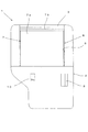
図1に示すように、自動車の右側のリアサイドドア1を例として説明すると、ドア1は、金属製のドアアウタパネルと、金属製のドアインナパネルと、樹脂製のドアトリム2とが結合されて構成され、ドアアウタパネルとドアインナパネルとの結合により、ドアトリム2の上部に窓枠3が形成され、この窓枠3に形成された窓開口5にこれを閉塞する全閉位置とドア本体2内に没入する全開位置との間でドアガラスが昇降可能に配設されて窓6が構成されている。
As shown in FIG. 1, the
また、図1に示すように、窓枠3には窓6を遮光するためのサンシェード7が設けられ、このサンシェード7は、窓開口5の下側であってドア本体2の上端内部にバネ力により巻き取り方向に付勢された状態でロール状に巻き取られた遮光シート7aと、遮光シート7aの上端に設けられた窓開口5の幅と略同寸法を有し窓枠3等に設けられた係止部に係止されて遮光シート7aを展開状態に保持する樹脂製の上部バー7bとを備え、窓6のドアガラス側に沿って遮光シート7aが上下方向に展開・収納自在にサンシェード7が配設されており、上部バー7bはドア本体2の内部に完全に没入することはなく、サンシェード7が収納されているときには、ドア本体2の上部に上部バー7bが露出した状態に保持され、露出状態の上部バー7bの把持部を持って引き上げることにより、遮光シート7aがバネの付勢力に抗して展開される。なお、図1中の9はドアハンドル、10はパワーウィンドウスイッチである。
As shown in FIG. 1, the
このとき、サンシェード7は、例えば遮光シート7aがロール状に巻き取られる中空円筒状のシャフトと、該シャフト内に配設されそれぞれ一端がシャフトの中央部に係止された一対のトーションバネとから成るサンシェードアッセンブリ12により、シャフトから引き伸ばされ、かつ、巻き取られる。さらに、サンシェードアッセンブリ12のシャフトの両端に位置する両トーションバネそれぞれの他端がアウタケース14に係止され、このアウタケース14がドアトリム2に取り付けられることにより、サンシェード7がドアトリム2の内側に展開・収納自在に固定される。
At this time, the
そして、シャフトまたはこのシャフトを包皮する中空円筒状のカバーに、長尺方向に平行に形成されたスリットに遮光シート7aの下端部が止着され、上部バー7bを把持して遮光シート7aを引き上げることにより遮光シート7aがシャフトから引き出され、サンシェード7が展開状態となり、上部バー7bを窓枠3等に設けられた係止部(図示せず)に係止することで、窓6が遮光される。
And the lower end part of the light shielding sheet 7a is fixed to the shaft or a hollow cylindrical cover covering the shaft to the slit formed in parallel with the longitudinal direction, the upper bar 7b is gripped and the light shielding sheet 7a is pulled up. As a result, the light shielding sheet 7a is pulled out from the shaft, the
一方、遮光シート7aの展開の際に、遮光シート7aを展開するに連れて両トーションバネのコイル部の捻じれ度合いが大きくなり、遮光シート7aを収納する際の巻き取り方向へのバネ力が蓄えられるため上部バー7bの係止を解除すると、両トーションバネのバネ力によって遮光シート7aがサンシェードアッセンブリ12のシャフトに巻き取られ、サンシェード7が収納状態になる。
On the other hand, when the light shielding sheet 7a is deployed, the degree of twisting of the coil portions of both torsion springs increases as the light shielding sheet 7a is deployed, and the spring force in the winding direction when the light shielding sheet 7a is stored is increased. When the upper bar 7b is unlocked because it is stored, the light shielding sheet 7a is wound around the shaft of the sunshade assembly 12 by the spring force of both torsion springs, and the
ところで、上記したアウタケース14は、図3に示すように、断面が平仮名のし字状をなす長尺の基部14aと、基部14aの上端に略水平に一体形成された水平部14bと、基部14aの下部に略垂直に一体形成された垂直部14cとにより構成され、基部14aとドアトリム2との間にサンシェードアッセンブリ12を収納するようになっている。なお、水平部14bの端部にはドアガラスとの間の隙間をシールするシール部材(図示せず)が配設される。
By the way, as shown in FIG. 3, the
さらに、図3、図4に示すように、複数個の断面コ字状の台座部16がドアトリム2に車室内側に突出して一体形成され、これら各台座部16の車室内側の側面(内側面)に係止孔16aが形成され、アウタケース14の垂直部14cの各係止孔16aそれぞれに対向する位置には車室外方向に突出してボス18が一体形成され、各ボス18の先端部に出没自在に弾性係止爪18aが一体形成されており、各ボス18が係止孔16aに挿通されると、各ボス18の係止爪18aが台座部16の内側に没入し、これにより各係止爪18aが係止孔16a周縁の台座部16の内側面に係止した状態になり、アウタケース14がドアトリム2に取り付け固定される。
Further, as shown in FIGS. 3 and 4, a plurality of
そして、アウタケース14を固定した状態では、図3に示すように、ドアトリム2の上端縁とアウタケース14の水平部14bとの間に隙間20が設けられ、サンシェード7の上部バー7bの上端が隙間20から少し覗くようにサンシェードアッセンブリ12が配設され、上部バー7bを引き上げることにより遮光シート7aが隙間20を移動してシャフトから繰り出されて展開される。
In the state where the
したがって、上記した実施形態によれば、ドアトリム2に設けられた台座部16の係止孔16aに、アウタケース14のボス18に設けられた係止爪18aを係止して、アウタケース14をドアトリム2に取り付けるため、他車両の側面衝突が生じたときには、ビス止めの場合のようにビスが突出することによる乗員の怪我が生じることもなく、アウタケース14だけを簡単に取り外せることから、アウタケース13を含むサンシェードアッセンブリ12に不具合が生じたときには、溶着する場合のようにサンシェードアッセンブリ12ごと交換する必要がなく、安全性の向上を図ると同時にコストの低減を図ることが可能になる。
Therefore, according to the above-described embodiment, the
なお、本発明は上記した実施形態に限定されるものではなく、その趣旨を逸脱しない限りにおいて上述したもの以外に種々の変更を行なうことが可能である。 The present invention is not limited to the above-described embodiment, and various modifications other than those described above can be made without departing from the spirit of the present invention.
上記した実施形態では、台座部16を断面コ字状として説明したが、この台座部の形状はこれに限定されないのはいうまでもない。
In the above-described embodiment, the
また、上記した実施形態では、本発明をリアサイドドア1に採用した場合について説明したが、本発明を適用可能な範囲はリアサイドドアに限定されるものはではない。
Moreover, although the case where this invention was employ | adopted as the
1 …サイドドア
2 …ドアトリム
6 …窓
7 …サンシェード
12 …サンシェードアッセンブリ
14 …アウタケース
16 …台座部
16a …係止孔
18a …係止爪
DESCRIPTION OF
Claims (1)
前記サイドドアのドアトリムに車室内側に突出して設けられた台座部と、
前記台座部の内側面に形成された係止孔と、
断面し字状をなす長尺の基部と、該基部の下部に略垂直に形成された垂直部とを有し、前記基部の車室内に向かう端縁が前記ドアトリムに当接した状態で、前記サンシェードを展開・収納自在に保持するサンシェードアッセンブリが前記基部と前記ドアトリムとの間に収納されて、前記ドアトリムの内側に前記サンシェードアッセンブリを取り付けるアウタケースと、
前記アウタケースの前記垂直部に設けられ前記係止孔に係止して前記アウタケースを前記ドアトリムに取り付ける係止爪と
を備えることを特徴とする車両用サンシェードアッセンブリ構造。 In a vehicle sunshade assembly structure for attaching a sunshade for shielding a window of a vehicle side door to the side door,
A pedestal portion provided on the door trim of the side door so as to protrude toward the vehicle interior side ;
A locking hole formed on the inner surface of the pedestal,
A long base portion having a cross-sectional shape and a vertical portion formed substantially perpendicular to the lower portion of the base portion, with the edge of the base portion facing the vehicle interior in contact with the door trim, A sunshade assembly that holds the sunshade in a freely deployable and retractable manner is housed between the base and the door trim, and an outer case that attaches the sunshade assembly to the inside of the door trim;
A vehicle sunshade assembly structure comprising a locking claw provided at the vertical portion of the outer case and locking the outer case to the door trim by locking in the locking hole.
Priority Applications (1)
| Application Number | Priority Date | Filing Date | Title |
|---|---|---|---|
| JP2013164009A JP6319967B2 (en) | 2013-08-07 | 2013-08-07 | Sunshade assembly structure for vehicles |
Applications Claiming Priority (1)
| Application Number | Priority Date | Filing Date | Title |
|---|---|---|---|
| JP2013164009A JP6319967B2 (en) | 2013-08-07 | 2013-08-07 | Sunshade assembly structure for vehicles |
Publications (2)
| Publication Number | Publication Date |
|---|---|
| JP2015030451A JP2015030451A (en) | 2015-02-16 |
| JP6319967B2 true JP6319967B2 (en) | 2018-05-09 |
Family
ID=52516134
Family Applications (1)
| Application Number | Title | Priority Date | Filing Date |
|---|---|---|---|
| JP2013164009A Active JP6319967B2 (en) | 2013-08-07 | 2013-08-07 | Sunshade assembly structure for vehicles |
Country Status (1)
| Country | Link |
|---|---|
| JP (1) | JP6319967B2 (en) |
Family Cites Families (4)
| Publication number | Priority date | Publication date | Assignee | Title |
|---|---|---|---|---|
| JP3566549B2 (en) * | 1998-06-19 | 2004-09-15 | アラコ株式会社 | Door sunshade assembly structure |
| JP2003300415A (en) * | 2002-04-09 | 2003-10-21 | Araco Corp | Vehicle door trim |
| JP2004314829A (en) * | 2003-04-17 | 2004-11-11 | Araco Corp | Sunshade device |
| EP1832453B1 (en) * | 2006-03-08 | 2008-09-24 | C.R.F. Società Consortile per Azioni | Sunshade device for motor-vehicles, with shape memory actuator |
-
2013
- 2013-08-07 JP JP2013164009A patent/JP6319967B2/en active Active
Also Published As
| Publication number | Publication date |
|---|---|
| JP2015030451A (en) | 2015-02-16 |
Similar Documents
| Publication | Publication Date | Title |
|---|---|---|
| JP6629049B2 (en) | Shade device for vehicle | |
| WO2010106767A1 (en) | Sunshade structure | |
| JP6319967B2 (en) | Sunshade assembly structure for vehicles | |
| JP5985234B2 (en) | Seat member fastening | |
| JP4685126B2 (en) | Sunshade equipment | |
| JP6340624B2 (en) | Sunshade device for vehicle | |
| JP6278211B2 (en) | Vehicle interior structure | |
| US20190176581A1 (en) | Vehicle door sun shade apparatus | |
| JP2008195267A (en) | Vehicular trim structure and its manufacturing method | |
| JP5407339B2 (en) | Sunshade equipment | |
| JP2012101570A (en) | Sunshade device | |
| JP4396382B2 (en) | Vehicle occupant protection structure | |
| JP4775099B2 (en) | Sunshade for automobile window glass | |
| EP2862738B1 (en) | Electric-powered sun visor for vehicle | |
| JP7135587B2 (en) | Vehicle interior materials | |
| JP6319966B2 (en) | Auto body structure | |
| JP2006306147A (en) | Tonneau cover device | |
| JP6673577B2 (en) | Sunshade structure | |
| JP6724728B2 (en) | Sunshade equipment | |
| JP2020029201A (en) | Interior material for vehicle | |
| WO2014006980A1 (en) | Door for vehicle | |
| JP2018070087A (en) | Sunshade device | |
| WO2023074625A1 (en) | Tonneau cover device | |
| JP2009280159A (en) | Sun shade device | |
| KR20140049871A (en) | Apparatus for door curtain of a car |
Legal Events
| Date | Code | Title | Description |
|---|---|---|---|
| A621 | Written request for application examination |
Free format text: JAPANESE INTERMEDIATE CODE: A621 Effective date: 20160804 |
|
| A977 | Report on retrieval |
Free format text: JAPANESE INTERMEDIATE CODE: A971007 Effective date: 20170725 |
|
| A131 | Notification of reasons for refusal |
Free format text: JAPANESE INTERMEDIATE CODE: A131 Effective date: 20170905 |
|
| A521 | Request for written amendment filed |
Free format text: JAPANESE INTERMEDIATE CODE: A523 Effective date: 20171025 |
|
| TRDD | Decision of grant or rejection written | ||
| A01 | Written decision to grant a patent or to grant a registration (utility model) |
Free format text: JAPANESE INTERMEDIATE CODE: A01 Effective date: 20180403 |
|
| A61 | First payment of annual fees (during grant procedure) |
Free format text: JAPANESE INTERMEDIATE CODE: A61 Effective date: 20180403 |
|
| R150 | Certificate of patent or registration of utility model |
Ref document number: 6319967 Country of ref document: JP Free format text: JAPANESE INTERMEDIATE CODE: R150 |
|
| R250 | Receipt of annual fees |
Free format text: JAPANESE INTERMEDIATE CODE: R250 |
|
| R250 | Receipt of annual fees |
Free format text: JAPANESE INTERMEDIATE CODE: R250 |
|
| R250 | Receipt of annual fees |
Free format text: JAPANESE INTERMEDIATE CODE: R250 |
|
| R250 | Receipt of annual fees |
Free format text: JAPANESE INTERMEDIATE CODE: R250 |