JP6319552B2 - Flue gas denitration apparatus and flue gas denitration method - Google Patents
Flue gas denitration apparatus and flue gas denitration method Download PDFInfo
- Publication number
- JP6319552B2 JP6319552B2 JP2013240848A JP2013240848A JP6319552B2 JP 6319552 B2 JP6319552 B2 JP 6319552B2 JP 2013240848 A JP2013240848 A JP 2013240848A JP 2013240848 A JP2013240848 A JP 2013240848A JP 6319552 B2 JP6319552 B2 JP 6319552B2
- Authority
- JP
- Japan
- Prior art keywords
- exhaust gas
- nox
- denitration
- concentration
- measured
- Prior art date
- Legal status (The legal status is an assumption and is not a legal conclusion. Google has not performed a legal analysis and makes no representation as to the accuracy of the status listed.)
- Active
Links
- UGFAIRIUMAVXCW-UHFFFAOYSA-N Carbon monoxide Chemical compound [O+]#[C-] UGFAIRIUMAVXCW-UHFFFAOYSA-N 0.000 title claims description 37
- 239000003546 flue gas Substances 0.000 title claims description 37
- 238000000034 method Methods 0.000 title claims description 9
- 239000007789 gas Substances 0.000 claims description 118
- 238000005259 measurement Methods 0.000 claims description 79
- 239000003054 catalyst Substances 0.000 claims description 46
- 238000009826 distribution Methods 0.000 claims description 37
- 238000011144 upstream manufacturing Methods 0.000 claims description 30
- 239000000779 smoke Substances 0.000 claims 1
- MWUXSHHQAYIFBG-UHFFFAOYSA-N Nitric oxide Chemical compound O=[N] MWUXSHHQAYIFBG-UHFFFAOYSA-N 0.000 description 303
- 238000002347 injection Methods 0.000 description 10
- 239000007924 injection Substances 0.000 description 10
- IJGRMHOSHXDMSA-UHFFFAOYSA-N Atomic nitrogen Chemical compound N#N IJGRMHOSHXDMSA-UHFFFAOYSA-N 0.000 description 2
- 239000003245 coal Substances 0.000 description 2
- 238000006477 desulfuration reaction Methods 0.000 description 2
- 230000023556 desulfurization Effects 0.000 description 2
- 239000000428 dust Substances 0.000 description 2
- 230000000694 effects Effects 0.000 description 2
- 230000006698 induction Effects 0.000 description 2
- 230000002378 acidificating effect Effects 0.000 description 1
- 230000032683 aging Effects 0.000 description 1
- BFNBIHQBYMNNAN-UHFFFAOYSA-N ammonium sulfate Chemical compound N.N.OS(O)(=O)=O BFNBIHQBYMNNAN-UHFFFAOYSA-N 0.000 description 1
- 229910052921 ammonium sulfate Inorganic materials 0.000 description 1
- 235000011130 ammonium sulphate Nutrition 0.000 description 1
- 239000002803 fossil fuel Substances 0.000 description 1
- 238000004519 manufacturing process Methods 0.000 description 1
- 229910052757 nitrogen Inorganic materials 0.000 description 1
- 239000000126 substance Substances 0.000 description 1
- XLYOFNOQVPJJNP-UHFFFAOYSA-N water Substances O XLYOFNOQVPJJNP-UHFFFAOYSA-N 0.000 description 1
Images


Landscapes
- Exhaust Gas Treatment By Means Of Catalyst (AREA)
Description
本発明は、石炭などの化石燃料をボイラ(燃焼器)で燃焼させる際に排出される排ガス中に含まれるNOx(窒素酸化物)を除去するのに用いられる排煙脱硝装置及び排煙脱硝方法に関するものである。 The present invention relates to a flue gas denitrification apparatus and a flue gas denitration method used to remove NOx (nitrogen oxide) contained in exhaust gas discharged when fossil fuel such as coal is burned in a boiler (combustor). It is about.
上記したような排煙脱硝装置としては、例えば、特許文献1に記載されたものがある。
この排煙脱硝装置は、ボイラから排出された排ガスが流れる煙道に配置されており、排ガスにNH3を注入する複数のNH3注入ノズルと、このNH3注入ノズルのガス流れ下流側に位置してNH3が注入された排ガスからNOxを除去する脱硝触媒を備えている。
As the above-described flue gas denitration device, for example, there is one described in
The denitrification device is disposed in the flue flows discharged flue gas from the boiler, and a plurality of NH 3 injection nozzle for injecting NH 3 in the exhaust gas, located in the gas flow downstream of the NH 3 injection nozzles Thus, a denitration catalyst for removing NOx from the exhaust gas into which NH 3 has been injected is provided.
ボイラの運用に伴って、ボイラから排出された排ガス分布パターンが変化すると、脱硝触媒出口におけるNOx及びNH3の各濃度分布(脱硝装置出口におけるNOx濃度分布及びNH3濃度分布)のばらつきが次第に大きくなるので、上記した排煙脱硝装置では、複数のNH3注入ノズルの各分配調整弁を操作して、NH3注入量の分配調整(NH3注入バランス調整)を行うことで、脱硝装置出口におけるNOx濃度分布及びNH3濃度分布をそれぞれ平準化するようにしている。 With the operation of the boiler, the exhaust gas distribution pattern discharged from the boiler is changed, variation in the concentration distribution of NOx and NH 3 in the denitration catalyst outlet (NOx concentration at the denitration unit outlet distribution and NH 3 concentration distribution) gradually increases Therefore, in the above-described flue gas denitration apparatus, by operating each distribution adjustment valve of a plurality of NH 3 injection nozzles and performing distribution adjustment (NH 3 injection balance adjustment) of the NH 3 injection amount, at the denitration apparatus outlet The NOx concentration distribution and the NH 3 concentration distribution are leveled.
ところが、上記した排煙脱硝装置において、複数のNH3注入ノズルの各分配調整弁を操作して行うNH3注入バランス調整は、通常、ボイラの常用負荷条件(100%定格負荷)の状態で成されるのが一般的であり、例えば、100%定格負荷を下回る部分負荷の状態でボイラを運用する場合には、ボイラからの排ガスの濃度分布パターンがさらに変化したとしても、100%定格負荷の状態の脱硝装置出口におけるNOx濃度分布及びNH3濃度分布に対応したNH3の注入量及びバランスのまま運用しなければならない。 However, in the above-described flue gas denitration apparatus, the NH 3 injection balance adjustment performed by operating each distribution adjusting valve of a plurality of NH 3 injection nozzles is normally performed under the normal load condition (100% rated load) of the boiler. For example, when a boiler is operated in a partial load state below 100% rated load, even if the concentration distribution pattern of exhaust gas from the boiler further changes, The NH 3 injection amount and balance corresponding to the NOx concentration distribution and NH 3 concentration distribution at the outlet of the denitration apparatus in the state must be operated.
つまり、上記した排煙脱硝装置では、脱硝出口NOx濃度分布及び脱硝出口NH3濃度分布の平準化が成されないまま運用せざるを得ない場合がないとは言えず、脱硝出口NH3濃度の局所的な増大によって、脱硝触媒の排ガス流れ下流側に位置するエアヒータ等の機器内部に酸性硫安の生成による目詰まりが生じる可能性があるという問題を有しており、この問題を解決することが従来の課題となっていた。 That is, the above-mentioned in denitrification device, not be said that there is no case management forced leave denitrification outlet NOx concentration distribution and leveling of the denitration outlet NH 3 concentration distribution is not performed, the denitrification outlet NH 3 concentrations of local As a result of this increase, there is a possibility that clogging due to the production of acidic ammonium sulfate may occur inside the device such as an air heater located downstream of the exhaust gas flow of the denitration catalyst. It was an issue.
本発明は、上記した従来の課題に着目してなされたもので、ボイラ運用の経年変化あるいは負荷状態にかかわらず、平準化した脱硝出口におけるNOx濃度分布及びNH3濃度分布をいずれも確保することができ、その結果、脱硝触媒の排ガス流れ下流側に位置する機器に及ぼすNH3による影響を少なく抑えることが可能である排煙脱硝装置及び排煙脱硝方法を提供することを目的としている。 The present invention has been made by paying attention to the above-described conventional problems, and ensures both the NOx concentration distribution and the NH 3 concentration distribution at the leveled denitration outlet regardless of aging or load conditions of boiler operation. As a result, an object of the present invention is to provide a flue gas denitration apparatus and a flue gas denitration method that can suppress the influence of NH 3 on equipment located on the downstream side of the exhaust gas flow of the denitration catalyst.
ここで、燃焼器から排出される排ガス中に含まれるNOxについては、煙道内の所定の計測点に配置される周知のNOx濃度計によって、瞬時に濃度を測定することができる。一方、NH3濃度の測定には、化学的な分析を行う必要があるため、瞬時にNH3濃度を取得することは不可能である。 Here, the NOx contained in the exhaust gas discharged from the combustor can be instantaneously measured by a known NOx concentration meter disposed at a predetermined measurement point in the flue. On the other hand, the measurement of the NH 3 concentration, it is necessary to perform chemical analysis, it is impossible to obtain the NH 3 concentration instantaneously.
本発明者は、NOx濃度が低い計測点のNH3濃度が高いことに着目し、脱硝触媒の出口においてNOx濃度を瞬時に測定して、このNOx濃度が低い部位を流れる流出排ガスを脱硝触媒の排ガス流れ上流側に戻すことで、脱硝出口NH3濃度が局所的に高くなる部位をなくし得ることを見出し、本発明をするに至った。 The inventor pays attention to the high NH 3 concentration at the measurement point where the NOx concentration is low, instantaneously measures the NOx concentration at the outlet of the denitration catalyst, and discharges the exhaust gas flowing through the portion where the NOx concentration is low to the denitration catalyst. By returning to the upstream side of the exhaust gas flow, it has been found that the site where the denitration outlet NH 3 concentration is locally high can be eliminated, and the present invention has been achieved.
すなわち、本発明の第1の態様は、燃焼器から排出される排ガスを導く煙道に配置されて、NH3を注入して前記排ガス中に含まれるNOxを除去する排煙脱硝装置であって、 前記排ガスからNOxを除去する脱硝処理を行う脱硝触媒と、前記脱硝触媒の排ガス流れ下流側で且つ該排ガス流れに対する面内において脱硝出口NOx濃度を複数箇所で計測する下流側計測部と、前記排ガスに注入するNH 3 の量のバランス調整により脱硝出口NOx濃度分布及び脱硝出口NH 3 濃度分布がいずれも平準化された状態において、前記下流側計測部における複数箇所の計測点のうちの局所的に低い脱硝出口NOx濃度を計測した計測点及びその近傍を流れる流出排ガスを吸引して、前記脱硝触媒の排ガス流れ上流側に戻して流す排ガス循環機構を備えている構成としている。
なお、局所的に低い脱硝出口NOx濃度を計測した計測点及びその近傍とは、下流側計測部の複数箇所の計測点で計測した脱硝出口NOx濃度の平均値を大幅に下回る脱硝出口NOx濃度を計測した計測点とその周囲の数箇所の計測点のことを指す。
That is, the first aspect of the present invention is a flue gas denitration apparatus that is disposed in a flue that guides exhaust gas discharged from a combustor and injects NH 3 to remove NOx contained in the exhaust gas. a denitration catalyst to perform denitration process for removing NOx from the exhaust gas, a downstream measurement unit that measures a denitration outlet NOx concentration at a plurality of locations in the plane relative to and exhaust gas flow exhaust flow downstream of the denitration catalyst, the In the state where both the NOx removal NOx concentration distribution and the NOx removal NH 3 concentration distribution are leveled by adjusting the balance of the amount of NH 3 injected into the exhaust gas, the local measurement point of the plurality of measurement points in the downstream measurement unit is local. An exhaust gas circulation mechanism for sucking out exhaust gas flowing in the vicinity of the measurement point where the NOx concentration at a low denitration outlet is measured and returning it to the upstream side of the exhaust flow of the denitration catalyst It is assumed that it is equipped.
In addition, the measurement point where the low denitration outlet NOx concentration was measured locally and its vicinity are the NOx removal NOx concentration that is significantly lower than the average value of the NOx removal NOx concentration measured at a plurality of measurement points in the downstream measurement unit. It refers to the measured measurement point and several measurement points around it.
また、本発明の第2の態様は、前記脱硝触媒の排ガス流れ上流側で且つ該排ガス流れに対する面内において脱硝入口NOx濃度を複数箇所で計測する上流側計測部を備え、前記排ガス循環機構は、前記下流側計測部における複数箇所の計測点のうちの局所的に低い脱硝出口NOx濃度を計測した計測点及びその近傍で吸引した流出排ガスを前記上流側計測部における複数箇所の計測点のうちの局所的に高い脱硝入口NOx濃度を計測した計測点及びその近傍に戻す構成としている。
この場合も、局所的に高い脱硝入口NOx濃度を計測した計測点及びその近傍とは、上流側計測部の複数箇所の計測点で計測した脱硝入口NOx濃度の平均値を大幅に上回る脱硝入口NOx濃度を計測した計測点とその周囲の数箇所の計測点のことを指す。
Further, the second aspect of the present invention includes an upstream side measurement unit that measures the NOx concentration at a plurality of locations on the upstream side of the exhaust gas flow of the denitration catalyst and in the plane with respect to the exhaust gas flow, and the exhaust gas circulation mechanism includes Among the plurality of measurement points in the upstream measurement unit, the measurement point at which the locally low NOx removal NOx concentration is measured among the plurality of measurement points in the downstream measurement unit and the exhaust gas sucked in the vicinity thereof In this configuration, the NOx concentration at a locally high NOx removal is returned to the measurement point and its vicinity.
In this case as well, the measurement point where the high NOx removal NOx concentration is locally measured and its vicinity are the NOx removal NOx concentration that greatly exceeds the average value of the NOx removal NOx concentration measured at a plurality of measurement points in the upstream measurement unit. It refers to the measurement point where the concentration was measured and several measurement points around it.
一方、本発明に係る排煙脱硝方法は、燃焼器から排出される排ガスを導く煙道に配置された脱硝触媒により、NH3を注入した排ガス中のNOxを除去するに際して、前記排ガスに注入するNH 3 の量のバランス調整を行って脱硝出口NOx濃度分布及び脱硝出口NH 3 濃度分布をいずれも平準化させて前記燃焼器の運用を開始し、前記脱硝触媒の排ガス流れ下流側で且つ該排ガス流れに対する面内において脱硝出口NOx濃度を複数箇所で計測し、計測した複数の脱硝出口NOx濃度のうちの局所的に低い脱硝出口NOx濃度を計測した計測点及びその近傍を流れる流出排ガスを吸引して、前記脱硝触媒の排ガス流れ上流側に戻して流す構成としている。 On the other hand, flue gas denitration method according to the present invention, when removed by a denitration catalyst disposed in the flue to guide the exhaust gas discharged from the combustor, the NOx in the exhaust gas injected NH 3, and injected into the flue gas The NO 3 concentration distribution of the denitration outlet and the NH 3 concentration distribution of the denitration outlet are leveled by adjusting the balance of the amount of NH 3 and the operation of the combustor is started, and the exhaust gas downstream of the denitration catalyst and the exhaust gas The NOx concentration at the NOx removal outlet is measured at a plurality of locations in the plane with respect to the flow, and the outflow exhaust gas flowing in the vicinity of the measurement point at which the NOx concentration at the locally low NOx removal NOx concentration is measured is measured. Thus, the denitration catalyst is configured to flow back to the upstream side of the exhaust gas flow.
本発明に係る排煙脱硝装置及び排煙脱硝方法において、脱硝触媒としては、ハニカム状に形成されたものを使用することができるが、他の方式の触媒を使用することができるのは言うまでもない。 In the flue gas denitration apparatus and the flue gas denitration method according to the present invention, as the denitration catalyst, those formed in a honeycomb shape can be used, but it goes without saying that other types of catalysts can be used. .
本発明に係る排煙脱硝装置及び排煙脱硝方法では、まず、適宜時点(適宜負荷条件)で排ガスに注入するNH3の量のバランス調整を行って、脱硝出口NOx濃度分布及び脱硝出口NH3濃度分布をいずれも平準化させる。 In the flue gas denitration apparatus and the flue gas denitration method according to the present invention, first, the balance of the amount of NH 3 injected into the exhaust gas at an appropriate time point (appropriate load condition) is adjusted to obtain the NOx concentration distribution and the denitration outlet NH 3. All concentration distributions are leveled.
次いで、燃焼器の運用を開始した段階において、脱硝触媒の排ガス流れ下流側で且つ該排ガス流れに対する面内の複数箇所で脱硝出口NOx濃度を計測する。 Next, at the stage where the operation of the combustor is started, the NOx concentration at the NOx removal outlet is measured at a plurality of locations on the downstream side of the exhaust gas flow of the NOx removal catalyst and in the plane relative to the exhaust gas flow.
そして、脱硝出口NOx濃度の低い部位が局所的に発生した場合には、この低い脱硝出口NOx濃度を計測した計測点及びその近傍を流れる流出排ガスを吸引して、脱硝触媒の排ガス流れ上流側に戻して流すと、脱硝出口NH3濃度が局所的に高くなっている部位がなくなるので、脱硝触媒の排ガス流れ下流側に位置する機器に及ぼすNH3による影響を少なく抑え得ることとなる。 And when the site | part with low NOx removal NOx density | concentration generate | occur | produced locally, the outflow exhaust gas which flows through the measurement point which measured this low NOx removal NOx density | concentration and its vicinity is sucked, and the exhaust gas flow upstream of the NOx removal catalyst When flowing back, there is no portion where the denitration outlet NH 3 concentration is locally high, so that the influence of NH 3 on the device located downstream of the denitration catalyst in the exhaust gas flow can be suppressed.
つまり、運用時の負荷の大小にかかわらず、平準化した脱硝出口NOx濃度分布及び脱硝出口NH3濃度分布を確保し得ることとなる。 That is, regardless of the load during operation, it is possible to ensure a uniform denitration outlet NOx concentration distribution and denitration outlet NH 3 concentration distribution.
この際、脱硝触媒の排ガス流れ上流側に上流側計測部を配置して、局所的に低い脱硝出口NOx濃度を計測した計測点及びその近傍で吸引した流出排ガスを上流側計測部の複数箇所の計測点のうちの局所的に高い脱硝入口NOx濃度を計測した計測点及びその近傍に戻すように成すと、脱硝出口NOx濃度分布及び脱硝出口NH3濃度分布の平準化がより一層効率よく成されることとなる。 At this time, an upstream measurement unit is arranged upstream of the exhaust gas flow of the denitration catalyst, and the measurement point at which the low NOx removal NOx concentration is locally measured and the exhaust gas sucked in the vicinity thereof at a plurality of locations in the upstream measurement unit. By returning to the measurement point where the locally high NOx removal NOx concentration was measured and returning to its vicinity, the NOx removal NOx concentration distribution and the NO3 removal NH 3 concentration distribution are more efficiently leveled. The Rukoto.
本発明に係る排煙脱硝装置では、燃焼器の運用時における負荷の大小にかかわらず、脱硝出口NH3濃度が局所的に高くなっている部位をなくすことができ、したがって、脱硝触媒の排ガス流れ下流側に位置する機器に及ぼすNH3による影響を少なく抑えることが可能であるという非常に優れた効果がもたらされる。 In the flue gas denitration apparatus according to the present invention, it is possible to eliminate the portion where the denitration outlet NH 3 concentration is locally high regardless of the load during operation of the combustor, and therefore, the exhaust gas flow of the denitration catalyst. A very excellent effect is obtained that it is possible to suppress the influence of NH 3 on the equipment located on the downstream side to a small extent.
以下、本発明の実施例を図面に基づいて説明する。
図1〜図3は、本発明の一実施例による排煙脱硝装置を示している。
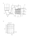
図1に示すように、この排煙脱硝装置10は、石炭焚きボイラ(燃焼器)Bの節炭部Baに垂直煙道1を介して接続しており、排煙脱硝装置10から煙突Pに至るまでの排ガス処理煙道2の下流側には、エアヒータ3、集塵装置4、誘引ファン5、熱交換器6、脱硫部7及び押込みファン8が順次配置されている。
Embodiments of the present invention will be described below with reference to the drawings.
1 to 3 show a flue gas denitration apparatus according to an embodiment of the present invention.
As shown in FIG. 1, the flue
エアヒータ3は、押込みファン9により導入される外部空気を排煙脱硝装置10から排出される排ガスの熱で暖めて石炭焚きボイラBに送り込み、熱交換器6は、誘引ファン5により導かれる集塵装置4通過後の排ガスと押込みファン8により導入される脱硫部7通過後の排ガスとの熱交換を行うものとなっている。
The
この排煙脱硝装置10は、図2(a)にも示すように、垂直煙道1に配置されて、排ガスにNH3を注入することでNOxを還元して窒素と水に変換するNH3注入ノズル11と、垂直煙道1の上端連結煙道1aから導入される白抜き矢印で示す排ガスが上から下に向けて流れるダクト12を横断するようにして複数段(この実施例では3段)設置された脱硝触媒13を具備しており、この脱硝触媒13は、排ガスとの接触面積が大きくなるようにハニカム状に形成されている。
The
また、この排煙脱硝装置10は、脱硝触媒13の排ガス流れ下流側で脱硝出口NOx濃度を計測する下流側計測部15を備えている。
Further, the flue
この下流側計測部15は、図2(b)に示すように、脱硝触媒13の排ガス流れに対する面内における複数箇所(この実施例では24箇所)に計測点((1,a),(1,b),…,(6,c),(6,d))を設定して成っており、これらの計測点((1,a),(1,b),…,(6,c),(6,d))において、周知のNOx濃度計によってそれぞれ瞬時にNOx濃度を測定することができるようになっている。
As shown in FIG. 2 (b), the downstream
さらに、この排煙脱硝装置10は、脱硝触媒13を通過した流出排ガスを脱硝触媒13の排ガス流れ上流側に戻す排ガス循環機構20を備えている。
Further, the flue
この排ガス循環機構20は、脱硝触媒13を通過した流出排ガスを吸引する排ガス吸引部22と、ダクト12を横断する方向(図2(a),(b)左右方向)に排ガス吸引部22を往復移動させる吸引駆動部23と、排ガス吸引部22で吸引した流出排ガスを脱硝触媒13の排ガス流れ上流側に圧送する排ガス循環ファン24と、この排ガス循環ファン24を介して圧送された流出排ガスを脱硝触媒13に向けて放出する排ガス放出部25を具備している。
This exhaust
この排ガス循環機構20では、下流側計測部15の複数箇所の計測点((1,a),(1,b),…,(6,c),(6,d))で計測した脱硝出口NOx濃度のうちの局所的に低い値の脱硝出口NOx濃度を計測した計測点及びその近傍に、吸引駆動部23によって排ガス吸引部22を移動させ、この計測点及びその近傍を流れる流出排ガスを排ガス吸引部22で吸引して、排ガス循環ファン24及び排ガス放出部25を介して脱硝触媒13の排ガス流れ上流側に戻すようになっている。
In the exhaust
さらに、この排煙脱硝装置10は、脱硝触媒13の排ガス流れ上流側で脱硝入口NOx濃度を計測する上流側計測部16を備えている。
Further, the flue
この上流側計測部16も、下流側計測部15と同様に、脱硝触媒13の排ガス流れに対する面内における複数箇所に計測点(図示省略)を設定して成っており、これらの計測点において、周知のNOx濃度計によってそれぞれ瞬時にNOx濃度を測定することができるようになっている。
Similarly to the downstream
この場合、排ガス循環機構20には、ダクト12を横断する方向(図2(a),(b)左右方向)に排ガス放出部25を往復移動させる放出駆動部26が具備されており、この排ガス循環機構20では、局所的に低い脱硝出口NOx濃度を計測した計測点及びその近傍で吸引した流出排ガスを脱硝触媒13の排ガス流れ上流側に戻す際に、上流側計測部16の複数箇所の計測点のうちの局所的に高い脱硝入口NOx濃度を計測した計測点及びその近傍に、放出駆動部26によって排ガス放出部25を移動させるようになっている。
In this case, the exhaust
つまり、この排ガス循環機構20では、例えば、図3の左側に示すように、局所的に低い脱硝出口NOx濃度(高い脱硝出口NH3濃度)を計測した計測点(5,b)及びその近傍の計測点(5,a),(5,c)の流出排ガスを吸引して、脱硝触媒13の排ガス流れ上流側の局所的に高い脱硝入口NOx濃度(低い脱硝入口NH3濃度)を計測した計測点及びその近傍に戻すようになっている。
That is, in the exhaust
この実施例に係る排煙脱硝装置10では、まず、適宜時点(適宜負荷条件)で複数のNH3注入ノズル11の図示しない各分配調整弁を操作して、排ガスに注入するNH3の量のバランス調整を行って、脱硝出口NOx濃度分布及び脱硝出口NH3濃度分布をいずれも平準化させる。
In the flue
次いで、ボイラBの運用を開始した段階において、脱硝触媒13の排ガス流れ下流側に位置する下流側計測部15の複数箇所の計測点((1,a),(1,b),…,(6,c),(6,d))で脱硝出口NOx濃度を定期的に計測して、脱硝出口NOx濃度の平均値を算出する。
Next, at the stage where the operation of the boiler B is started, a plurality of measurement points ((1, a), (1, b), ..., () in the
そして、この脱硝出口NOx濃度の平均値を下回る部位が局所的に発生した場合には、この平均値を下回る脱硝出口NOx濃度を計測した計測点及びその近傍(図3左側では計測点(5,b)及びその近傍の計測点(5,a),(5,c))を流れる流出排ガスを排ガス循環機構20の排ガス吸引部22により吸引して、脱硝触媒13の排ガス流れ上流側に戻して流すと、図3右側に示すように、脱硝出口NH3濃度が局所的に高くなっている部位がなくなるので、脱硝触媒13の排ガス流れ下流側に位置するエアヒータ3等の機器に及ぼすNH3による影響を少なく抑え得ることとなる。
And when the site | part less than the average value of this NOx removal NOx density | concentration generate | occur | produced locally, the measurement point which measured the NOx removal NOx density | concentration below this average value, and its vicinity (on the left side of FIG. 3, measurement point (5, b) and the exhaust gas flowing through the measurement points (5, a), (5, c) in the vicinity thereof are sucked by the exhaust
この際、上流側計測部16の複数箇所の計測点で脱硝入口NOx濃度を定期的に計測して、脱硝入口NOx濃度の平均値を算出しておき、この平均値を上回る部位が局所的に存在する場合には、上流側計測部16の複数箇所の計測点のうちの平均値を上回る脱硝入口NOx濃度を計測した計測点及びその近傍に排ガス循環機構20の排ガス放出部25を移動させて、これらの部位に計測点(5,b)及びその近傍の計測点(5,a),(5,c)で吸引した脱硝出口NOx濃度の低い流出排ガスを戻すように成すと、脱硝出口NOx濃度分布及び脱硝出口NH3濃度分布の平準化が効率よく成されることとなる。
At this time, the NOx removal NOx concentration is periodically measured at a plurality of measurement points of the
つまり、この実施例に係る排煙脱硝装置10では、運用時の負荷の大小にかかわらず、平準化した脱硝出口NOx濃度分布及び脱硝出口NH3濃度分布を確保し得ることとなって、脱硝出口NH3濃度が局所的に高くなっている部位をなくし得ることとなる。
That is, in the flue
本発明に係る排煙脱硝装置の構成は、上記した実施例に限定されるものではなく、他の構成として、例えば、脱硝出口NOx濃度の低い部位が局所的に発生した場合に、この低い脱硝出口NOx濃度を計測した下流側計測部15の計測点及びその近傍を流れる流出排ガスを排ガス循環機構20の排ガス吸引部22によって自動的に吸引して、脱硝触媒13の排ガス流れ上流側に戻して流すようにしてもよい。
The configuration of the flue gas denitration device according to the present invention is not limited to the above-described embodiment. As another configuration, for example, when a portion having a low NOx removal NOx concentration is locally generated, this low denitration device is used. The exhaust gas flowing in the vicinity of the measurement point of the downstream
1 垂直煙道
10 排煙脱硝装置
13 脱硝触媒
15 下流側計測部
16 上流側計測部
20 排ガス循環機構
22 排ガス吸引部(排ガス循環機構)
23 吸引駆動部(排ガス循環機構)
24 排ガス循環ファン(排ガス循環機構)
25 排ガス放出部(排ガス循環機構)
26 放出駆動部(排ガス循環機構)
B 石炭焚きボイラ(燃焼器)
DESCRIPTION OF
23 Suction drive (exhaust gas circulation mechanism)
24 Exhaust gas circulation fan (exhaust gas circulation mechanism)
25 Exhaust gas discharge part (exhaust gas circulation mechanism)
26 Release drive (exhaust gas circulation mechanism)
B Coal fired boiler (combustor)
Claims (3)
前記排ガスからNOxを除去する脱硝処理を行う脱硝触媒と、
前記脱硝触媒の排ガス流れ下流側で且つ該排ガス流れに対する面内において脱硝出口NOx濃度を複数箇所で計測する下流側計測部と、
前記排ガスに注入するNH 3 の量のバランス調整により脱硝出口NOx濃度分布及び脱硝出口NH 3 濃度分布がいずれも平準化された状態において、前記下流側計測部における複数箇所の計測点のうちの局所的に低い脱硝出口NOx濃度を計測した計測点及びその近傍を流れる流出排ガスを吸引して、前記脱硝触媒の排ガス流れ上流側に戻して流す排ガス循環機構を備えている排煙脱硝装置。 A flue gas denitration device that is disposed in a flue that guides exhaust gas discharged from a combustor and injects NH 3 to remove NOx contained in the exhaust gas,
A denitration catalyst for performing a denitration process for removing NOx from the exhaust gas;
A downstream measurement unit that measures the NOx concentration at a plurality of locations on the downstream side of the exhaust gas flow of the denitration catalyst and in the plane with respect to the exhaust gas flow;
In the state where both the NOx removal NOx concentration distribution and the NOx removal NH 3 concentration distribution are leveled by the balance adjustment of the amount of NH 3 injected into the exhaust gas, the local measurement point among the plurality of measurement points in the downstream measurement unit A flue gas denitrification device comprising an exhaust gas circulation mechanism that sucks outflow exhaust gas flowing in the vicinity of the measurement point where the NOx concentration at a low denitration outlet is measured and the vicinity thereof and flows it back to the upstream side of the exhaust flow of the denitration catalyst.
前記排ガスに注入するNH 3 の量のバランス調整を行って脱硝出口NOx濃度分布及び脱硝出口NH 3 濃度分布をいずれも平準化させて前記燃焼器の運用を開始し、
前記脱硝触媒の排ガス流れ下流側で且つ該排ガス流れに対する面内において脱硝出口NOx濃度を複数箇所で計測し、
計測した複数の脱硝出口NOx濃度のうちの局所的に低い脱硝出口NOx濃度を計測した計測点及びその近傍を流れる流出排ガスを吸引して、前記脱硝触媒の排ガス流れ上流側に戻して流す排煙脱硝方法。 When removing NOx in the exhaust gas injected with NH 3 by the denitration catalyst arranged in the flue leading the exhaust gas discharged from the combustor,
And both were leveled denitration outlet NOx concentration distribution and denitrification outlet NH 3 concentration distribution performed balance of the amount of NH 3 injected into the flue gas to initiate the operation of the combustor,
The NOx concentration at the NOx removal outlet is measured at a plurality of locations on the downstream side of the exhaust gas flow of the NOx removal catalyst and in the plane with respect to the exhaust gas flow,
Smoke exhaust that sucks outflow exhaust gas flowing in and near the measurement point at which the locally low NOx removal NOx concentration is measured among a plurality of measured NOx removal NOx concentrations and flows back to the exhaust gas flow upstream side of the denitration catalyst Denitration method.
Priority Applications (1)
| Application Number | Priority Date | Filing Date | Title |
|---|---|---|---|
| JP2013240848A JP6319552B2 (en) | 2013-11-21 | 2013-11-21 | Flue gas denitration apparatus and flue gas denitration method |
Applications Claiming Priority (1)
| Application Number | Priority Date | Filing Date | Title |
|---|---|---|---|
| JP2013240848A JP6319552B2 (en) | 2013-11-21 | 2013-11-21 | Flue gas denitration apparatus and flue gas denitration method |
Publications (2)
| Publication Number | Publication Date |
|---|---|
| JP2015100722A JP2015100722A (en) | 2015-06-04 |
| JP6319552B2 true JP6319552B2 (en) | 2018-05-09 |
Family
ID=53376926
Family Applications (1)
| Application Number | Title | Priority Date | Filing Date |
|---|---|---|---|
| JP2013240848A Active JP6319552B2 (en) | 2013-11-21 | 2013-11-21 | Flue gas denitration apparatus and flue gas denitration method |
Country Status (1)
| Country | Link |
|---|---|
| JP (1) | JP6319552B2 (en) |
Families Citing this family (4)
| Publication number | Priority date | Publication date | Assignee | Title |
|---|---|---|---|---|
| JP6586812B2 (en) * | 2015-07-31 | 2019-10-09 | 中国電力株式会社 | Coal-fired power generation facility |
| CN109569294A (en) * | 2019-01-31 | 2019-04-05 | 福建鑫泽环保设备工程有限公司 | Magnesite shaft furnace flue gas NO_x Reduction by Effective equipment and its technique |
| CN112044268B (en) * | 2019-06-05 | 2022-08-16 | 中冶长天国际工程有限责任公司 | Method and system for utilizing heat energy in flue gas treatment |
| CN112879655B (en) * | 2020-12-25 | 2022-06-21 | 成都建工工业设备安装有限公司 | Installation method for fire damper of parallel air pipe |
Family Cites Families (4)
| Publication number | Priority date | Publication date | Assignee | Title |
|---|---|---|---|---|
| JPS6034720A (en) * | 1983-08-08 | 1985-02-22 | Babcock Hitachi Kk | Denitration apparatus by catalytic reduction with ammonia for reprocessing off gas |
| JPH0724258A (en) * | 1993-07-12 | 1995-01-27 | Kobe Steel Ltd | Catalytic denitrizer |
| CA2206236C (en) * | 1996-07-08 | 2001-10-30 | The Boc Group, Inc. | Removal of nitrogen oxides from gas streams |
| JP4079414B2 (en) * | 2002-04-03 | 2008-04-23 | 三菱重工業株式会社 | Nitrogen oxide processing apparatus and nitrogen oxide processing method |
-
2013
- 2013-11-21 JP JP2013240848A patent/JP6319552B2/en active Active
Also Published As
| Publication number | Publication date |
|---|---|
| JP2015100722A (en) | 2015-06-04 |
Similar Documents
| Publication | Publication Date | Title |
|---|---|---|
| JP6319552B2 (en) | Flue gas denitration apparatus and flue gas denitration method | |
| JP5931506B2 (en) | Denitration apparatus and reducing agent distribution adjustment method for denitration apparatus | |
| CN101637701B (en) | Gas turbine combustor exhaust gas spray cooling for NOx control using selective catalytic reductions | |
| CN103328786B (en) | Gas turbine and air inlet segmentation thereof and flue gas recirculation method | |
| CN102626585A (en) | V-type ammonia spraying and mixing system for SCR (Selective Catalytic Reduction) smoke denitrification device | |
| JP5594368B2 (en) | Ammonia injection equipment | |
| JP6542568B2 (en) | Fluid mixing device and denitration device provided with fluid mixing device | |
| JP6179774B2 (en) | Demister unit and EGR system including the same | |
| JP2011230047A (en) | Exhaust gas desulfurizer and oxygen combustion apparatus and method having the same | |
| RU2606298C1 (en) | Exhaust system | |
| JP6702547B2 (en) | Denitration system and denitration method | |
| JP6733352B2 (en) | Oxidation catalyst and exhaust gas purification system | |
| CN101476736B (en) | Rapid turn flue flow equalization device | |
| JP2011031209A (en) | Wet type flue gas desulfurization apparatus | |
| JP6156628B2 (en) | Flue gas denitration apparatus and flue gas denitration method | |
| JP2011125766A (en) | Exhaust gas treatment apparatus | |
| CN111228997A (en) | Cascaded injection apparatus of ozone denitration | |
| CN109224849A (en) | A kind of trapezoidal SCR reactor assembly equipped with ladder rectifier | |
| KR101526773B1 (en) | Back pressure reducing system for diesel vehicle and operation-method thereof | |
| US10731846B2 (en) | Boiler facility and operating method thereof | |
| JP6783164B2 (en) | Exhaust gas treatment equipment | |
| US20140199218A1 (en) | Method and apparatus for zero emission combined heat and power | |
| JP6195059B2 (en) | Flue gas denitration equipment | |
| JPH1128337A (en) | Ammonia supply method in denitration equipment | |
| DK180165B1 (en) | Denitrator |
Legal Events
| Date | Code | Title | Description |
|---|---|---|---|
| A621 | Written request for application examination |
Free format text: JAPANESE INTERMEDIATE CODE: A621 Effective date: 20160921 |
|
| A977 | Report on retrieval |
Free format text: JAPANESE INTERMEDIATE CODE: A971007 Effective date: 20170925 |
|
| A131 | Notification of reasons for refusal |
Free format text: JAPANESE INTERMEDIATE CODE: A131 Effective date: 20171101 |
|
| A521 | Written amendment |
Free format text: JAPANESE INTERMEDIATE CODE: A523 Effective date: 20171227 |
|
| TRDD | Decision of grant or rejection written | ||
| A01 | Written decision to grant a patent or to grant a registration (utility model) |
Free format text: JAPANESE INTERMEDIATE CODE: A01 Effective date: 20180307 |
|
| A61 | First payment of annual fees (during grant procedure) |
Free format text: JAPANESE INTERMEDIATE CODE: A61 Effective date: 20180320 |
|
| R151 | Written notification of patent or utility model registration |
Ref document number: 6319552 Country of ref document: JP Free format text: JAPANESE INTERMEDIATE CODE: R151 |