JP6319210B2 - Connector and connector device - Google Patents
Connector and connector device Download PDFInfo
- Publication number
- JP6319210B2 JP6319210B2 JP2015133537A JP2015133537A JP6319210B2 JP 6319210 B2 JP6319210 B2 JP 6319210B2 JP 2015133537 A JP2015133537 A JP 2015133537A JP 2015133537 A JP2015133537 A JP 2015133537A JP 6319210 B2 JP6319210 B2 JP 6319210B2
- Authority
- JP
- Japan
- Prior art keywords
- plug
- socket
- wall
- wall portion
- connector
- Prior art date
- Legal status (The legal status is an assumption and is not a legal conclusion. Google has not performed a legal analysis and makes no representation as to the accuracy of the status listed.)
- Active
Links
- 230000003014 reinforcing effect Effects 0.000 claims description 110
- 239000002184 metal Substances 0.000 claims description 28
- 229910052751 metal Inorganic materials 0.000 claims description 28
- 238000005476 soldering Methods 0.000 claims description 14
- 230000002093 peripheral effect Effects 0.000 claims description 12
- 230000013011 mating Effects 0.000 claims description 6
- 229920003002 synthetic resin Polymers 0.000 claims description 6
- 239000000057 synthetic resin Substances 0.000 claims description 6
- 230000002787 reinforcement Effects 0.000 description 22
- 238000003780 insertion Methods 0.000 description 14
- 230000037431 insertion Effects 0.000 description 14
- 238000005452 bending Methods 0.000 description 12
- 238000000605 extraction Methods 0.000 description 12
- 239000000463 material Substances 0.000 description 8
- 238000009434 installation Methods 0.000 description 5
- 229910000881 Cu alloy Inorganic materials 0.000 description 4
- PCHJSUWPFVWCPO-UHFFFAOYSA-N gold Chemical compound [Au] PCHJSUWPFVWCPO-UHFFFAOYSA-N 0.000 description 4
- 239000010931 gold Substances 0.000 description 4
- 229910052737 gold Inorganic materials 0.000 description 4
- 238000009413 insulation Methods 0.000 description 4
- 238000007747 plating Methods 0.000 description 4
- 229920005989 resin Polymers 0.000 description 4
- 239000011347 resin Substances 0.000 description 4
- 229920000106 Liquid crystal polymer Polymers 0.000 description 3
- 239000004977 Liquid-crystal polymers (LCPs) Substances 0.000 description 3
- ATJFFYVFTNAWJD-UHFFFAOYSA-N Tin Chemical compound [Sn] ATJFFYVFTNAWJD-UHFFFAOYSA-N 0.000 description 2
- 230000006378 damage Effects 0.000 description 2
- 239000007769 metal material Substances 0.000 description 2
- 238000000465 moulding Methods 0.000 description 2
- 229910052709 silver Inorganic materials 0.000 description 2
- 239000004332 silver Substances 0.000 description 2
- 230000004308 accommodation Effects 0.000 description 1
- 230000000694 effects Effects 0.000 description 1
- 238000004519 manufacturing process Methods 0.000 description 1
- 238000012986 modification Methods 0.000 description 1
- 230000004048 modification Effects 0.000 description 1
Images


Classifications
-
- H—ELECTRICITY
- H01—ELECTRIC ELEMENTS
- H01R—ELECTRICALLY-CONDUCTIVE CONNECTIONS; STRUCTURAL ASSOCIATIONS OF A PLURALITY OF MUTUALLY-INSULATED ELECTRICAL CONNECTING ELEMENTS; COUPLING DEVICES; CURRENT COLLECTORS
- H01R12/00—Structural associations of a plurality of mutually-insulated electrical connecting elements, specially adapted for printed circuits, e.g. printed circuit boards [PCB], flat or ribbon cables, or like generally planar structures, e.g. terminal strips, terminal blocks; Coupling devices specially adapted for printed circuits, flat or ribbon cables, or like generally planar structures; Terminals specially adapted for contact with, or insertion into, printed circuits, flat or ribbon cables, or like generally planar structures
- H01R12/70—Coupling devices
- H01R12/71—Coupling devices for rigid printing circuits or like structures
- H01R12/72—Coupling devices for rigid printing circuits or like structures coupling with the edge of the rigid printed circuits or like structures
- H01R12/73—Coupling devices for rigid printing circuits or like structures coupling with the edge of the rigid printed circuits or like structures connecting to other rigid printed circuits or like structures
-
- H—ELECTRICITY
- H01—ELECTRIC ELEMENTS
- H01R—ELECTRICALLY-CONDUCTIVE CONNECTIONS; STRUCTURAL ASSOCIATIONS OF A PLURALITY OF MUTUALLY-INSULATED ELECTRICAL CONNECTING ELEMENTS; COUPLING DEVICES; CURRENT COLLECTORS
- H01R13/00—Details of coupling devices of the kinds covered by groups H01R12/70 or H01R24/00 - H01R33/00
- H01R13/02—Contact members
-
- H—ELECTRICITY
- H01—ELECTRIC ELEMENTS
- H01R—ELECTRICALLY-CONDUCTIVE CONNECTIONS; STRUCTURAL ASSOCIATIONS OF A PLURALITY OF MUTUALLY-INSULATED ELECTRICAL CONNECTING ELEMENTS; COUPLING DEVICES; CURRENT COLLECTORS
- H01R12/00—Structural associations of a plurality of mutually-insulated electrical connecting elements, specially adapted for printed circuits, e.g. printed circuit boards [PCB], flat or ribbon cables, or like generally planar structures, e.g. terminal strips, terminal blocks; Coupling devices specially adapted for printed circuits, flat or ribbon cables, or like generally planar structures; Terminals specially adapted for contact with, or insertion into, printed circuits, flat or ribbon cables, or like generally planar structures
- H01R12/70—Coupling devices
- H01R12/71—Coupling devices for rigid printing circuits or like structures
- H01R12/712—Coupling devices for rigid printing circuits or like structures co-operating with the surface of the printed circuit or with a coupling device exclusively provided on the surface of the printed circuit
- H01R12/716—Coupling device provided on the PCB
-
- H—ELECTRICITY
- H01—ELECTRIC ELEMENTS
- H01R—ELECTRICALLY-CONDUCTIVE CONNECTIONS; STRUCTURAL ASSOCIATIONS OF A PLURALITY OF MUTUALLY-INSULATED ELECTRICAL CONNECTING ELEMENTS; COUPLING DEVICES; CURRENT COLLECTORS
- H01R13/00—Details of coupling devices of the kinds covered by groups H01R12/70 or H01R24/00 - H01R33/00
- H01R13/46—Bases; Cases
- H01R13/502—Bases; Cases composed of different pieces
Description
本発明は、コネクタおよびコネクタ装置に関する。特に、本発明は、2枚のプリント配線基板間の電気的接続に用いるプラグ、ソケット等のコネクタ、およびプラグとソケットとからなるコネクタ装置に関する。 The present invention relates to a connector and a connector device. In particular, the present invention relates to a connector such as a plug and a socket used for electrical connection between two printed wiring boards, and a connector device including a plug and a socket.
従来、2枚のプリント配線基板をケーブルを介さず直に電気的に接続するためのコネクタ装置が知られている。このコネクタ装置は、一方のプリント配線基板に実装されるプラグと、他方のプリント配線基板に実装されるソケットとからなり、プラグをソケットに嵌合することにより、両プリント配線基板のプリント配線同士を電気的に接続している(例えば、特許文献1参照)。 2. Description of the Related Art Conventionally, a connector device for directly connecting two printed wiring boards directly without using a cable is known. This connector device comprises a plug mounted on one printed wiring board and a socket mounted on the other printed wiring board. By fitting the plug into the socket, the printed wirings of both printed wiring boards can be connected to each other. They are electrically connected (see, for example, Patent Document 1).
近年、コネクタの小サイズ化や薄型化が進み、コネクタの強度が低下してきている。これは、コネクタのハウジングが樹脂材で形成されており、その小サイズ化や薄肉化により、必要な強度を維持するのが難しくなってきたためである。そのため、コネクタの挿抜作業時に発生する応力に耐えられずハウジングの破壊が生じる可能性があった。 In recent years, the connector has been reduced in size and thickness, and the strength of the connector has been reduced. This is because the housing of the connector is made of a resin material, and it has become difficult to maintain the required strength due to the reduction in size and thickness. For this reason, there is a possibility that the housing may be broken because it cannot withstand the stress generated during the connector insertion / extraction operation.
図19(a)は、例としてコネクタの抜去作業の様子を示している。プラグ10とソケット20との嵌合により2枚のプリント配線基板30、40が連結された状態から、一方のプリント配線基板30の端を指50で持ち上げることにより、他方のプリント配線基板40に実装されたソケット20からプラグ10を抜き取っている。しかしながら、このような作業では、図19(b)およびそのA部拡大図である図19(c)中に符号Bで示される箇所に応力が集中してハウジングの破壊が生じる可能性があった。この部分は、肉薄で樹脂材のみから形成されており、他の部分に比べて強度が弱く、抜去作業時に加わる外力に耐えられず破断等の破壊が起こりやすいからである。このため、この周辺を補強金具で補強することが行われている(例えば、特許文献1参照)。
FIG. 19A shows the state of the connector removal work as an example. From the state in which the two printed
特許文献1に開示されたプラグコネクタでは、補強部材として機能する金属製のプラグ部材が第1プラグ壁部に設けられている。この金属製のプラグ部材は、第2プラグ壁部に埋め込まれる一対の第3プラグ板部を有し、第1プラグ壁部と第2プラグ壁部との接続箇所を補強している。
In the plug connector disclosed in
また、特許文献1に開示されたレセプタクルコネクタでは、補強部材として機能する金属製のレセプタクル部材が第1レセプタクル壁部に設けられている。この金属製のレセプタクル部材は、第2レセプタクル壁部に埋め込まれる一対の第6レセプタクル板部を有し、第1レセプタクル壁部と第2レセプタクル壁部との接続箇所を補強している。
Moreover, in the receptacle connector disclosed in
しかしながら、特許文献1に開示されたプラグコネクタでは、補強金具である第3プラグ板部を有するプラグ部材が、プラグコンタクトとは別体として構成されているので、端に位置するプラグコンタクトと補強金具との間に樹脂材だけからなる肉薄で強度の弱いハウジング部位が少なからず残っていた。また、別体の補強金具を設けるとなると、ハウジングにそのための設置スペースが必要となるので、コネクタの更なる小型化の要請に応えられないという問題もあった。
However, in the plug connector disclosed in
また、特許文献1に開示されたレセプタクルコネクタでは、補強金具である第6レセプタクル板部を有するレセプタクル部材が、レセプタクルコンタクトとは別体として構成されているので、端に位置するレセプタクルコンタクトと補強金具との間に樹脂材だけからなる肉薄で強度の弱いハウジング部位が少なからず残っていた。また、上述のように、別体の補強金具を設けるとなると、ハウジングにそのための設置スペースが必要となるので、コネクタの更なる小型化の要請に応えられないという問題もあった。
Further, in the receptacle connector disclosed in
本発明は、このような課題を解決するためになされたもので、コネクタの挿抜作業時にハウジングの破壊が生じないようにハウジングを補強することができると共に、コネクタを小型化することができるコネクタおよびコネクタ装置を提供することを目的としている。 The present invention has been made to solve such a problem, and a connector that can reinforce the housing so that the housing is not destroyed during connector insertion / extraction work, and can reduce the size of the connector. An object of the present invention is to provide a connector device.
本発明に係るコネクタは、上記目的を達成するため、一方のプリント配線基板に実装され、他方のプリント配線基板に実装された相手方コネクタと嵌合することにより、両プリント配線基板を電気的に接続するためのコネクタであって、互いに平行に離間配置された一対の第1壁部と、前記一対の第1壁部の長手方向に直交する方向に互いに平行に離間配置され、前記一対の第1壁部の各々の長手方向両端部が対向内側面に接続された一対の第2壁部と、を有する略矩形枠状の外周壁を備えた合成樹脂製のハウジングと、前記一対の第1壁部の各々に前記第1壁部の長手方向に沿って間隔をおいて配置された金属製の複数のコンタクトと、を有し、前記複数のコンタクトのうち前記第1壁部の長手方向の端に位置するコンタクトの各々が補強部を有し、前記補強部は前記端に位置するコンタクトの各々から一体に前記長手方向に沿って延在し、かつ、前記補強部の少なくとも一部において延在する方向の周囲全てが前記第2壁部の内部に埋入した構成をしている。 In order to achieve the above object, the connector according to the present invention is mounted on one printed wiring board and electrically connected to the other printed wiring board by fitting with a mating connector mounted on the other printed wiring board. A pair of first wall portions spaced apart in parallel to each other, and spaced apart in parallel to each other in a direction perpendicular to the longitudinal direction of the pair of first wall portions, the pair of first walls A synthetic resin housing having a substantially rectangular frame-shaped outer peripheral wall having a pair of second wall portions each having a longitudinal end portion of each wall portion connected to opposite inner side surfaces, and the pair of first walls A plurality of metal contacts disposed at intervals along the longitudinal direction of the first wall portion, and the longitudinal end of the first wall portion of the plurality of contacts. Each of the contacts located in is reinforced Has the reinforcing portion extends along the longitudinal direction integrally from the respective contact positioned in the end, and the extending directions around all of the second at least part of the reinforcing portion It is configured to be embedded inside the wall.
この構成により、端のコンタクトが存在する第1壁部のハウジング部位から第2壁部に至る範囲のハウジングを漏れなく確実に補強することができる。このため、コネクタの挿抜作業時にハウジングの破壊が生じるのを効果的に防止することができる。また、別体の補強金具を用いなくても有効な補強を行うことができるので、ハウジングにそのための設置スペースを確保する必要がなく、コネクタを小型化することができる。 With this configuration, the housing in the range from the housing portion of the first wall portion where the end contact exists to the second wall portion can be reliably reinforced without leakage. For this reason, it is possible to effectively prevent the housing from being destroyed during the connector insertion / extraction operation. Further, since effective reinforcement can be performed without using a separate reinforcing metal fitting, it is not necessary to secure an installation space in the housing, and the connector can be miniaturized.
本発明に係るコネクタは、前記複数のコンタクトの各々が、互いに平行な外側面部と内側面部とをそれぞれの端部間で接続した断面略U字状の部分を有し、前記外側面部と前記内側面部の少なくとも一方が前記第1壁部の側面に対向して配置され、前記補強部が、前記外側面部および前記内側面部のいずれか一方から一体に前記長手方向に延在して板状に形成された構成としてもよい。 In the connector according to the present invention, each of the plurality of contacts has a substantially U-shaped section in which an outer surface portion and an inner surface portion that are parallel to each other are connected between the respective end portions, and the outer surface portion and the inner surface portion At least one of the surface portions is disposed so as to face the side surface of the first wall portion, and the reinforcing portion is integrally formed from either one of the outer side surface portion and the inner side surface portion in the longitudinal direction to form a plate shape. A configuration may be adopted.
この構成により、板状の補強部がハウジングの第1壁部の側面に略平行になるよう配置される。すなわち、板状の補強部がハウジングの第1壁部および第2壁部の高さ方向に立設されるので、コネクタの挿抜作業時にハウジングの第1壁部と第2壁部との接続部に該高さ方向から加わる外力に対して高い剛性をもつことができる。 With this configuration, the plate-shaped reinforcing portion is disposed so as to be substantially parallel to the side surface of the first wall portion of the housing. That is, since the plate-like reinforcing portion is erected in the height direction of the first wall portion and the second wall portion of the housing, the connecting portion between the first wall portion and the second wall portion of the housing during the connector insertion / extraction operation It is possible to have high rigidity against external force applied from the height direction.
本発明に係るコネクタは、前記複数のコンタクトの各々が、互いに平行な外側面部と内側面部とをそれぞれの端部間で接続した断面略U字状の部分を有し、前記外側面部と前記内側面部の少なくとも一方が前記第1壁部の側面に対向して配置され、前記補強部が、前記外側面部および前記内側面部の両方からそれぞれ一体に前記長手方向に延在して2枚の板状に形成された構成としてもよい。 In the connector according to the present invention, each of the plurality of contacts has a substantially U-shaped section in which an outer surface portion and an inner surface portion that are parallel to each other are connected between the respective end portions, and the outer surface portion and the inner surface portion At least one of the surface portions is disposed to face the side surface of the first wall portion, and the reinforcing portion integrally extends from both the outer side surface portion and the inner side surface portion in the longitudinal direction to form two plates. It is good also as a structure formed in.
この構成により、端に位置するコンタクトの各々が、板状の補強部を2枚備えて、その一部をハウジングの第2壁部の内部に埋入させているので、端のコンタクトから第1壁部と第2壁部との接続部に至る範囲におけるハウジングの強度を格段に高めることができる。 With this configuration, each of the contacts located at the end includes two plate-like reinforcing portions, and a part of the contacts is embedded in the second wall portion of the housing. The strength of the housing in the range reaching the connecting portion between the wall portion and the second wall portion can be remarkably increased.
また、本発明に係るコネクタは、前記補強部が前記第2壁部の内部において前記第2壁部の長手方向に折れ曲がった折曲部を有するようにしてもよい。 In the connector according to the present invention, the reinforcing portion may have a bent portion that is bent in the longitudinal direction of the second wall portion inside the second wall portion.
この構成により、ハウジングの第1壁部と第2壁部との接続がより強固になるので、コネクタの挿抜作業においてハウジングの破壊が生じるのを効果的に防止することができる。また、この折曲部はハウジングの第2壁部の内部で第2壁部の長手方向に延びているので、第2壁部自体の補強にもなっている。 With this configuration, since the connection between the first wall portion and the second wall portion of the housing becomes stronger, it is possible to effectively prevent the housing from being destroyed during the connector insertion / removal operation. Moreover, since this bending part is extended in the longitudinal direction of the 2nd wall part inside the 2nd wall part of a housing, it is also reinforcement of 2nd wall part itself.
また、本発明に係るコネクタは、前記補強部が、前記一方のプリント配線基板に半田付けされる半田付け部、および前記相手方コネクタとの前記嵌合を固定するためのロック部をそれぞれ前記補強部から一体で延設した構成としてもよい。 Further, in the connector according to the present invention, the reinforcing portion includes a soldering portion to be soldered to the one printed wiring board, and a lock portion for fixing the fitting with the counterpart connector, respectively. It is good also as a structure extended integrally from.
この構成により、端のコンタクトから一体で形成された補強部から、さらに一体で半田付け部とロック部を形成しているので、端のコンタクトから第1壁部と第2壁部との接続部に至る範囲におけるハウジングの強度をさらに高めることができる。また、端のコンタクトと半田付け部とロック部とを一体で形成しているので、部品点数が減り、コストの削減にもなる。 With this configuration, since the soldering portion and the lock portion are integrally formed from the reinforcing portion integrally formed from the end contact, the connection portion between the first wall portion and the second wall portion is formed from the end contact. The strength of the housing in the range up to can be further increased. In addition, since the end contact, the soldering portion, and the lock portion are integrally formed, the number of parts is reduced and the cost is also reduced.
また、本発明のコネクタ装置は、プラグとして用いられる上記いずれか1つのコネクタと、前記プラグに嵌合するソケットとして用いられるコネクタまたは前記プラグに嵌合するソケットとして用いられる上記いずれか1つのコネクタと、を有する構成をしている。 Moreover, the connector device of the present invention includes any one of the above connectors used as a plug and any one of the above connectors used as a socket that fits into the plug or a socket that fits into the plug. , Has a configuration having.
本発明によれば、コネクタの挿抜作業時にハウジングの破壊が生じないようにハウジングを補強することができると共に、コネクタを小型化することができるコネクタおよびコネクタ装置を提供することができる。 ADVANTAGE OF THE INVENTION According to this invention, while a housing can be reinforced so that destruction of a housing may not arise at the time of the insertion / extraction operation | work of a connector, the connector and connector apparatus which can reduce a connector can be provided.
以下、本発明の実施形態に係るコネクタおよびコネクタ装置について、図面を参照して説明する。 Hereinafter, a connector and a connector device according to embodiments of the present invention will be described with reference to the drawings.
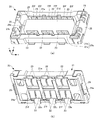
コネクタ装置1は、2枚のプリント配線基板同士を電気的に接続するためのものであり、図1に示すプラグ10と、図2に示すソケット20と、から構成される。
The
プラグ10は、一方のプリント配線基板に実装され、ソケット20は、他方のプリント配線基板に実装され、プラグ10とソケット20とを嵌合することにより、両プリント配線基板の電気回路を電気的に接続する。図3(a)は嵌合前のプラグ10とソケット20を上方から見た斜視図であり、(b)は下方から見た斜視図である。図4(a)は嵌合した状態のプラグ10とソケット20を上方から見た斜視図であり、(b)は下方から見た斜視図である。嵌合の際には、プラグ10側の略矩形枠型のプラグ外周壁11cが、ソケット20側のソケットハウジング21のソケット外周壁21cと中央凸部21dとの間に形成された嵌合溝部29に挿入されるようになっている。
The
プリント配線基板にはフレキシブルプリント配線基板も含めるものとする。すなわち、本実施形態に係るコネクタ装置1は、2枚のリジッドなプリント配線基板間、1枚のリジッドなプリント配線基板と1枚のフレキシブルプリント配線基板間、または2枚のフレキシブルプリント配線基板間の電気的接続に用いられる。
The printed wiring board includes a flexible printed wiring board. In other words, the
プラグ10のプリント配線基板への実装は、図1に示すプラグコンタクト12、13のプラグ端子片12c、13cやプラグロック部18の固定片18bなどをプリント配線基板の所定のランドに半田付けすることにより行われる。ソケット20のプリント配線基板への実装についても、同様に、図2に示すソケットコンタクト22、23のソケット端子片22c、23cや補強金具28などをプリント配線基板の所定のランドに半田付けすることにより行われる。
The
次に、第1の実施形態に係るプラグ10について図面を参照して説明する。
Next, the
[第1の実施形態]
図1(a)はプラグ10を上方から見た斜視図であり、(b)は下方から見た斜視図であり、(c)は(a)のI−I断面図である。プラグ10は、図1(a)および(b)に示すように、全体の構造を形成する合成樹脂製のプラグハウジング11と、金属製の複数のプラグコンタクト12、13とを有している。プラグコンタクト12、13は、相手方コネクタであるソケット20のソケットコンタクト22、23にそれぞれ接触することにより電気的な接続を実現するようになっている。このプラグ10は、例えばインサート成形によって製造することができる。
[First Embodiment]
1A is a perspective view of the
プラグハウジング11は、略矩形枠状のプラグ外周壁11cを備えている。このプラグ外周壁11cは、一対のプラグ第1壁部11aと、一対のプラグ第2壁部11bとを有している。一対のプラグ第1壁部11aは、互いに平行に離間配置されている。一対のプラグ第2壁部11bは、一対のプラグ第1壁部11aの長手方向に直交する方向(y軸方向)に互いに平行に離間配置され、一対のプラグ第1壁部11aの各々の長手方向(x軸方向)両端部が、一対のプラグ第2壁部11bの対向内側面に接続されている。プラグ外周壁11cで囲まれた内側には底壁11dを有している。
The
プラグハウジング11は、液晶ポリマー(Liquid Crystal Polymer:LCP)などの合成樹脂の成形品であり、構造を維持するための剛性と、プラグコンタクト12、13間の絶縁を確保するための絶縁性を有する。
The
複数のプラグコンタクト12、13が、一対のプラグ第1壁部11aの各々にそのプラグ第1壁部11aの長手方向に沿って間隔をあけて配置されている。図1に示すプラグ10では、各プラグ第1壁部11aに合計3個のプラグコンタクト12、13を配置しているが、個数は3に限定されるものではなく、2個以上である限り3より多くても少なくてもよい。
The plurality of
図5(a)は、図1のプラグ10に用いられる全てのプラグコンタクト12、13をプラグハウジング11における配置通りに示した斜視図であり、(b)はその下方から見た斜視図であり、(c)は(a)のV−V断面図である。図5(a)および(b)に示すように、プラグ第1壁部11aの長手方向(x軸方向)両端部に存在する端のプラグコンタクト13と、それらの間に挟まれて配置された中間のプラグコンタクト12とが用いられている。
FIG. 5A is a perspective view showing all the
中間のプラグコンタクト12と端のプラグコンタクト13は、共通の構成として、互いに平行なプラグ外側面部12b、13bとプラグ内側面部12a、13aとをそれぞれの端部間で接続した断面略U字状のプラグU字状部12u、13uを有している。このプラグ外側面部12b、13bとプラグ内側面部12a、13aの両方がプラグ第1壁部11aの側面に対向して配置されている。すなわち、プラグコンタクト12、13の各々は、プラグU字状部12u、13uがプラグ第1壁部11aに被さるように配置されている。
The
また、共通の構成として、プラグコンタクト12、13におけるプラグU字状部12u、13uのプラグ外側面部12b、13bには、係合凹部12d、13dが形成されている。この係合凹部12d、13dが、図2に示すソケットコンタクト22、23側のソケットU字状部22u、23uのソケット内側面部22a、23aに形成された係合凸部22f、23fと係合するようになっている。これにより、プラグコンタクト12、13とソケットコンタクト22、23の接触がより確実なものとなる。
Further, as a common configuration, engagement recesses 12d and 13d are formed in the plug
また、各プラグコンタクト12、13は、共通の構成として、プラグU字状部12u、13uの下端部から外方向に突出するプラグ端子片12c、13cを有している。プラグコンタクト12、13は、例えば、銅合金等の金属薄板を打ち抜き成形および折り曲げ加工した後、金メッキ等を施すことによって形成することができる。
Moreover, each
図5(a)および(b)に示すように、各プラグ第1壁部11aに配列された複数のプラグコンタクト12、13のうち、プラグ第1壁部11aの長手方向の端に位置するプラグコンタクト13の各々には、プラグ補強部13eが設けられている。このプラグ補強部13eは、端のプラグコンタクト13から一体で長手方向に沿って延在し、かつ、プラグ補強部13eの少なくとも一部がプラグ第2壁部11bの内部に埋入した構成となっている。
As shown in FIGS. 5A and 5B, among the plurality of
このプラグ補強部13eは、端のプラグコンタクト13から一体で形成されることから、プラグコンタクト13と同じ金属材料により製造されるのが好都合である。ただし、プラグ補強部13eはプラグハウジング11の補強を目的としているので、金メッキ等は必要に応じて省いてもよい。
Since the
プラグ補強部13eは、プラグ第1壁部11aの幅方向(y軸方向)から見て矩形状の板材であるが、補強機能を有する限り、任意の形状の板材とすることができ、板材に代えて例えば棒状等の部材とすることもできる。
The
上述した構成により、本実施形態に係るプラグ10は、端のプラグコンタクト13の各々がプラグ補強部13eを有し、このプラグ補強部13eが端のプラグコンタクト13の各々から一体に長手方向に沿って延在し、かつ、プラグ補強部13eの少なくとも一部がプラグ第2壁部11bの内部に埋入している。このため、端のプラグコンタクト13が存在するプラグ第1壁部11aのハウジング部位からプラグ第2壁部11bに至る範囲のプラグハウジング11を漏れなく確実に補強することができる。この範囲のプラグハウジング11は、プラグ10の挿抜作業時に破断等の破壊が起こりやすい部分であるから、挿抜作業時の破断等の破壊を有効に防止することができる。仮に挿抜作業時にプラグハウジング11の上記範囲において破断等の破壊が生じたとしても、端のプラグコンタクト13から一体で形成されたプラグ補強部13eにより、プラグハウジング11自体の形状を保持することができる。端のプラグコンタクト13自体も、このようなプラグ補強部13eを一体で形成していることにより、プラグ第1壁部11aの幅方向(y軸方向)の外力に対して、端のプラグコンタクト13の強度を高めることができる。また、端のプラグコンタクト13とは別体の補強金具と併存させることもできるが、別体の補強金具を用いなくて有効な補強を行うことができる。別体の補強金具を用いなくともよいので、プラグハウジング11にそのための設置スペースを確保する必要がなく、プラグ10を小型化することができる。
With the configuration described above, in the
プラグハウジング11のプラグ第2壁部11bには、図6に示す金属製のプラグロック部18が設けられている。プラグロック部18は、例えば銅合金に銀や錫などのメッキが施されたものであり、外面にロック凹部18aが設けられ、内面下端に外向きの固定片18bが設けられている。プラグ10をソケット20に嵌合する際、プラグロック部18のロック凹部18aが、ソケット20側の補強金具28の内面に設けられたロック凸部28aに係合することにより、プラグ10とソケット20との嵌合をより確実なものにしている。
The plug
プラグ補強部13eは、詳しくは図5(a)および(b)に示すように、端のプラグコンタクト13におけるプラグU字状部13uのプラグ内側面部13aから、一体で長手方向外向きに延在して板状に形成されている。板状のプラグ補強部13eの肉厚は、一体形成されるプラグ内側面部13aの肉厚に等しいが、必要に応じて肉厚を違えてもよい。
As shown in detail in FIGS. 5 (a) and 5 (b), the
したがって、板状のプラグ補強部13eがプラグハウジング11のプラグ第1壁部11aの内側面に略平行になるよう配置される。すなわち、板状のプラグ補強部13eがプラグハウジング11のプラグ第1壁部11aおよびプラグ第2壁部11bの高さ方向(z軸方向)に立設される。このため、コネクタの挿抜作業時にプラグハウジング11のプラグ第1壁部11aとプラグ第2壁部11bとの接続部およびその周辺に対して該高さ方向から加わる外力に対して高い剛性をもつことができる。
Therefore, the plate-like
次に、第2の実施形態に係るプラグ10について説明する。
Next, the
[第2の実施形態]
図7および図8に示すように、プラグコンタクト12、14の各々は、共通の構成として、互いに平行なプラグ外側面部12b、14bとプラグ内側面部12a、14aとをそれぞれの端部間で接続した断面略U字状のプラグU字状部12u、14uを有している。このプラグ外側面部12b、14bとプラグ内側面部12a、14aの両方がプラグ第1壁部11aの側面に対向して配置されている。すなわち、プラグコンタクト12、14の各々は、プラグU字状部12u、14uがプラグ第1壁部11aに被さるように配置されている。
[Second Embodiment]
As shown in FIGS. 7 and 8, each of the
各プラグ第1壁部11aの長手方向に沿って配列された複数のプラグコンタクト12、14のうち、端に位置するプラグコンタクト14の各々に、プラグ補強部14eが設けられている。このプラグ補強部14eは、プラグコンタクト14におけるプラグU字状部14uのプラグ外側面部14bから、一体で上記長手方向に延在して板状に形成されている。そして、プラグ補強部14eの少なくとも一部は、プラグ第2壁部11bの内部に埋入するよう構成されている。板状のプラグ補強部14eの肉厚は、一体形成されるプラグ外側面部14bの肉厚に等しくしているが、必要に応じて肉厚を違えてもよい。
Among the plurality of
したがって、板状のプラグ補強部14eがプラグハウジング11のプラグ第1壁部11aの外側側面に略平行になるよう配置される。すなわち、板状のプラグ補強部14eがプラグハウジング11のプラグ第1壁部11aおよびプラグ第2壁部11bの高さ方向に立設されている。このため、プラグ10の挿抜作業時にプラグハウジング11のプラグ第1壁部11aとプラグ第2壁部11bとの接続部およびその周辺に対して該高さ方向から加わる外力に対して高い剛性をもつことができる。
Therefore, the plate-like
その他の部分は、第1の実施形態と同様であるので、同一の部分には同一の符号を付し、説明を省略する。 Since other parts are the same as those in the first embodiment, the same parts are denoted by the same reference numerals and description thereof is omitted.
次に、第3の実施形態に係るプラグ10について説明する。
Next, the
[第3の実施形態]
図9および図10に示すように、プラグコンタクト12、15の各々は、共通の構成として、互いに平行なプラグ外側面部12b、15bとプラグ内側面部12a、15aとをそれぞれの端部間で接続した断面略U字状のプラグU字状部12u、15uを有している。このプラグ外側面部12b、15bとプラグ内側面部12a、15aの両方がプラグ第1壁部11aの側面に対向して配置されている。すなわち、プラグコンタクト12、15の各々は、プラグU字状部12u、15uがプラグ第1壁部11aに被さるように配置されている。
[Third Embodiment]
As shown in FIGS. 9 and 10, each of the
各プラグ第1壁部11aの長手方向に沿って配列された複数のプラグコンタクト12、15のうち、端に位置するプラグコンタクト15の各々に、2つのプラグ補強部15eが設けられている。そのうち、一方のプラグ補強部15eは、この端のプラグコンタクト15におけるプラグU字状部15uのプラグ外側面部15bから一体で上記長手方向に延在して板状に形成されている。また、他方のプラグ補強部15eは、端のプラグコンタクト15におけるプラグU字状部15uのプラグ内側面部15aから一体で上記長手方向に延在して板状に形成されている。各プラグ補強部15eの少なくとも一部は、プラグ第2壁部11bの内部に埋入するよう構成されている。2つのうちの一方のプラグ補強部15eのみ、その少なくとも一部をプラグ第2壁部11bの内部に埋入するように構成してもよい。板状の2つのプラグ補強部15eの肉厚は、一体形成されるプラグ外側面部15bおよびプラグ内側面部15aの肉厚にそれぞれ等しくしているが、必要に応じて肉厚を違えてもよい。
Of the plurality of
このように、プラグ補強部15eは、端のプラグコンタクト15の各々が、板状のプラグ補強部15eを2つ備えて、各プラグ補強部15eの一部をプラグ第2壁部11bの内部に埋入させている。このため、端のプラグコンタクト15からプラグ第1壁部11aとプラグ第2壁部11bとの接続部に至る範囲におけるプラグハウジング11の強度を格段に高めることができる。
As described above, each of the
その他の部分は、第1の実施形態と同様であるので、同一の部分には同一の符号を付し、説明を省略する。 Since other parts are the same as those in the first embodiment, the same parts are denoted by the same reference numerals and description thereof is omitted.
次に、第4の実施形態に係るプラグ10について説明する。
Next, the
[第4の実施形態]
図11および図12に示すように、プラグコンタクト12、16の各々は、共通の構成として、互いに平行なプラグ外側面部12b、16bとプラグ内側面部12a、16aとをそれぞれの端部間で接続した断面略U字状のプラグU字状部12u、16uを有している。このプラグ外側面部12b、16bとプラグ内側面部12a、16aの両方がプラグ第1壁部11aの側面に対向して配置されている。すなわち、プラグコンタクト12、16の各々は、プラグU字状部12u、16uがプラグ第1壁部11aに被さるように配置されている。
[Fourth Embodiment]
As shown in FIG. 11 and FIG. 12, each of the
各プラグ第1壁部11aの長手方向に沿って配列された複数のプラグコンタクト12、16のうち、端に位置するプラグコンタクト16の各々に、プラグ補強部16eが設けられている。このプラグ補強部16eは、プラグ第2壁部11bの内部においてプラグ第2壁部11bの長手方向に折れ曲がったプラグ折曲部16fを有するように構成されている。詳しくは、プラグ補強部16eがプラグ外側面部16bから延在しており、空きスペースの観点からプラグ第2壁部11bの長手方向内向きに折り曲げられている。しかし、折れ曲げ方向はこれに限定されるものではなく、プラグ第2壁部11bの内部に空きスペースがあれば、長手方向外向きに折れ曲がるようにしてもよい。
Among the plurality of
また、プラグ補強部16eをプラグ内側面部16aから延在させて、プラグ第2壁部11bの内部においてプラグ第2壁部11bの長手方向に折れ曲がったプラグ折曲部16fを有するように構成してもよい。折れ曲げ方向は、プラグ第2壁部11bの長方向内向きでもよいし、必要に応じて、スペースが空いている長手方向外向きでもよい。
Further, the
また、各プラグ補強部16eが、プラグ第2壁部11bの長手方向外向きに折れ曲がったプラグ折曲部16fと長手方向内向きに折れ曲ったプラグ折曲部16fを2つ備えるようにしてもよい。また、必要に応じて、プラグ折曲部16fをさらにプラグ第2壁部11bの幅方向に折り曲げるなどしてプラグ第2壁部11bとプラグ補強部16eとの連結をさらに強化することもできる。
Each
上述した構成により、プラグ第1壁部11aとプラグ第2壁部11bとの接続がより強固になるので、挿抜作業においてプラグハウジング11の破壊が生じるのを効果的に防止することができる。また、このプラグ折曲部16fはプラグ第2壁部11bの内部でプラグ第2壁部11bの長手方向に延びているので、プラグ第2壁部11b自体の補強にもなっている。
With the above-described configuration, the connection between the plug
その他の部分は、第1の実施形態と同様であるので、同一の部分には同一の符号を付し、説明を省略する。 Since other parts are the same as those in the first embodiment, the same parts are denoted by the same reference numerals and description thereof is omitted.
次に、第5の実施形態に係るプラグ10について説明する。
Next, a
[第5の実施形態]
図13および図14に示すように、プラグコンタクト12、17の各々は、共通の構成として、互いに平行なプラグ外側面部12b、17bとプラグ内側面部12a、17aとをそれぞれの端部間で接続した断面略U字状のプラグU字状部12u、17uを有している。このプラグ外側面部12b、17bとプラグ内側面部12a、17aの両方がプラグ第1壁部11aの側面に対向して配置されている。すなわち、プラグコンタクト12、17の各々は、プラグU字状部12u、17uがプラグ第1壁部11aに被さるように配置されている。
[Fifth Embodiment]
As shown in FIGS. 13 and 14, each of the
各プラグ第1壁部11aの長手方向に沿って配列された複数のプラグコンタクト12、17のうち、端に位置するプラグコンタクト17の各々に、プラグ補強部17eが設けられている。このプラグ補強部17eは、プラグ補強部17eにおいてプラグ第2壁部11bの高さ方向下端部から一体でプラグ第2壁部11bの長手方向外向きに半田付け部17gを延設するように構成されている。この半田付け部17gは、プラグ10が実装されるプリント配線基板の実装面の所定のランドに半田付けされることにより、プラグ10とプリント配線基板との連結を強化する。
Among the plurality of
プラグ補強部17eは、半田付け部17gに加えて、プラグ補強部17eにおいてプラグ第2壁部11bの高さ方向上端部から一体でプラグ第2壁部11bの外側面に配置されたロック部17hを延設するように構成されている。ロック部17hの外面には固定用凹部17jが形成され、ソケット20側の対応するロック用凸部に係合することにより、プラグ10とソケット20との嵌合を固定するようになっている。また、半田付け部17gとロック部17hの一方だけをプラグ補強部17eに延設するように構成してもよい。
In addition to the
このように、端のプラグコンタクト17から一体で形成されたプラグ補強部17eから、さらに一体で半田付け部17gとロック部17hを形成している。このため、端のプラグコンタクト17からプラグ第1壁部11aとプラグ第2壁部11bとの接続部に至る範囲におけるプラグハウジング11の強度をさらに高めることができる。また、端のプラグコンタクト17と半田付け部17gとロック部17hとを一体で形成しているので、部品点数が減り、コストの削減にもなる。
Thus, the
その他の部分は、第1の実施形態と同様であるので、同一の部分には同一の符号を付し、説明を省略する。 Since other parts are the same as those in the first embodiment, the same parts are denoted by the same reference numerals and description thereof is omitted.
なお、第1ないし第4の実施形態のいずれか1つの構成に加えて、第5の実施形態の構成を設けるようにしてもよい。また、プラグ10についての第5の実施形態と同様の構成をソケット20に適用することもできる。
In addition to the configuration of any one of the first to fourth embodiments, the configuration of the fifth embodiment may be provided. Further, the same configuration as that of the fifth embodiment of the
以上、コネクタとして用いるプラグ10について実施形態を説明してきたが、以下では、コネクタとして用いるソケット20の実施形態を説明する。まず、第6の実施形態に係るソケット20について図面を参照して説明する。
Although the embodiment of the
[第6の実施形態]
ソケット20は、図2(a)および(b)に示すように、全体の構造を形成する合成樹脂製のソケットハウジング21と、金属製の複数のソケットコンタクト22、23と、を有している。ソケットコンタクト22、23は、相手方コネクタであるプラグ10側のプラグコンタクト12、13にそれぞれ接触することにより電気的な接続が行われるようになっている。このソケット20は、例えばインサート成形によって製造することができる。
[Sixth Embodiment]
As shown in FIGS. 2A and 2B, the
ソケットハウジング21は、略矩形枠状のソケット外周壁21cを備えている。このソケット外周壁21cは、一対のソケット第1壁部21aと、一対のソケット第2壁部21bとを有している。一対のソケット第1壁部21aは、互いに平行に離間配置された構成としている。一対のソケット第2壁部21bは、ソケット第1壁部21aの長手方向に直交する方向(y軸方向)に互いに平行に離間配置されている。そして、一対のソケット第1壁部21aの各々の長手方向(x軸方向)両端部が、一対のソケット第2壁部21bの対向内側面に接続されるように構成されている。ソケット外周壁21cで囲まれた内側には中央凸部21dが設けられ、この中央凸部21dとソケット外周壁21cとの間に略矩形枠状の嵌合溝部29を形成している。
The
ソケットハウジング21には、ソケット第1壁部21aの幅方向(y軸方向)に沿ってソケット外周壁21cの内側面から嵌合溝部29を経て中央凸部21dの側面に至る範囲に、ソケットコンタクト22、23を収容するための収容凹部21fが設けられている。
The
ソケットハウジング21は、液晶ポリマーなどの合成樹脂の成形品であり、構造を維持するための剛性と、ソケットコンタクト22間の絶縁を確保するための絶縁性を有する。
The
複数のソケットコンタクト22、23が、一対のソケット第1壁部21aの各々にそのソケット第1壁部21aの長手方向に沿って間隔をあけて配置されている。図2に示すソケット20では、各ソケット第1壁部21aに合計3個のソケットコンタクト22、23を配置しているが、個数は3に限定されるものではなく、2個以上である限り3より多くても少なくてもよい。
The plurality of
図15は、図2に示すようなハウジング構造のソケット20に用いられるソケットコンタクト全てをソケットハウジング21における配置通りに示した斜視図である。図15に示すように、ソケット第1壁部21aの長手方向(x軸方向)両端部に存在する端のソケットコンタクト23と、それらの間に挟まれて配置された中間のソケットコンタクト22とが用いられている。
FIG. 15 is a perspective view showing all socket contacts used in the
ソケットコンタクト22、23の各々は、共通の構成として、互いに平行なソケット外側面部22b、23bとソケット内側面部22a、23aとをそれぞれの端部間で接続した断面略U字状のソケットU字状部22u、23uを有している。このソケット外側面部22b、23bとソケット内側面部22a、23aのいずれか一方がソケット第1壁部21aの側面に対向して配置される構造を有している。図2では、ソケットコンタクト22のソケット外側面部22bがソケット第1壁部21aの側面に対向して配置されている。
Each of the
また、各ソケットコンタクト22、23は、共通の構成として、ソケットU字状部22u、23uに離間対向するよう配置された断面略U字状のバネ部22d、23dを有している。ソケットU字状部22u、23uとバネ部22d、23dとは高さ方向(z軸方向)下端部同士が接続されている。ソケットコンタクト22、23は、ソケットU字状部22u、23uがソケット第1壁部21aの内側側面に対向し、バネ部22d、23dが中央凸部21dの側面に対向するように、収容凹部21fに嵌められる。ソケットU字状部22u、23uとバネ部22d、23dとでプラグコンタクト12、13を弾力的に挟み込むようになっている。
Moreover, each
また、各ソケットコンタクト22、23は、共通の構成として、ソケットU字状部22u、23uの高さ方向(z軸方向)下端部から外方向に突出するソケット端子片22c、23cを有している。
Moreover, each
また、共通の構成として、ソケットU字状部22u、23uのソケット内側面部22a、23aには、係合凸部22f、23fが形成されている。図15では、一例として、各ソケットコンタクト22、23につき1つの係合凸部22f、23fが設けられる構成を示している。係合凸部22f、23fの個数は任意であるが、相手方の各プラグコンタクト12、13に設けられる係合凹部12d、13dの個数に合わせるのが、確実なコンタクト接触を維持する上で好ましい。
Further, as a common configuration, engagement
ソケットコンタクト22、23は、例えば、銅合金等の金属薄板を打ち抜き成形および折り曲げ加工した後、金メッキ等を施すことによって形成することができる。
The
図15に示すように、各ソケット第1壁部21aに配列された複数のソケットコンタクト22、23のうち、ソケット第1壁部21aの長手方向の端に位置するソケットコンタクト23の各々には、ソケット補強部23eが設けられている。このソケット補強部23eは、端のソケットコンタクト23から一体に該長手方向に沿って延在し、かつ、ソケット補強部23eの少なくとも一部がソケット第2壁部21bの内部に埋入した構成となっている。
As shown in FIG. 15, among the plurality of
このソケット補強部23eは、端のソケットコンタクト23と一体で形成されることから、ソケットコンタクト23と同じ金属材料により製造されるのが好都合である。ただし、ソケット補強部23eはソケットハウジング21の補強を目的としているので、金メッキ等は必要に応じて省いてもよい。
Since the
ソケット補強部23eは、ソケット第1壁部21aの幅方向(y軸方向)から見て矩形状の板材であるが、補強機能を有する限り、任意の形状の板材とすることができ、板材に代えて例えば棒状等の部材とすることもできる。
The
上述した構成により、本実施形態のソケット20では、端のソケットコンタクト23の各々に設けられたソケット補強部23eが、それぞれの端のソケットコンタクト23から一体に長手方向に沿って延在している。そして、ソケット補強部23eの少なくとも一部がソケット第2壁部21bの内部に埋入している。これにより、端のソケットコンタクト23が存在するソケット第1壁部21aのハウジング部位からソケット第2壁部21bに至る範囲のソケットハウジング21を漏れなく確実に補強することができる。この範囲のソケットハウジング21は、ソケット20の挿抜作業時に破断等の破壊が起こりやすい部分であるから、挿抜作業時の破断等の破壊を有効に防止することができる。仮に挿抜作業時にソケットハウジング21の上記範囲において破断が生じたとしても、端のソケットコンタクト23から一体で形成されたソケット補強部23eにより、ソケットハウジング21自体の形状を保持することができる。端のソケットコンタクト23自体も、このようなソケット補強部23eを一体で形成していることにより、ソケット第1壁部21aの幅方向(y軸方向)の外力に対して、端のソケットコンタクト23の強度を高めることができる。また、端のソケットコンタクト23とは別体の補強金具と併存させることもできるが、別体の補強金具を用いなくて有効な補強を行うことができる。別体の補強金具を用いなくてもよいので、ソケットハウジング21にそのための設置スペースを確保する必要がなく、ソケット20を小型化することができる。
With the configuration described above, in the
ソケットハウジング21のソケット第2壁部21bには、図2に示すような補強金具28が設けられている。補強金具28は、例えば銅合金に銀や錫などのメッキが施されたものであり、内面にロック凸部28aが設けられ、必要に応じてその外面下端に半田付け部が設けられている。プラグ10をソケット20に嵌合する際、補強金具28のロック凸部28aが、プラグロック部18の外面に設けられたロック凹部18aに係合することにより、プラグ10とソケット20との嵌合をより確実なものにしている。
A reinforcing metal fitting 28 as shown in FIG. 2 is provided on the socket
ソケット補強部23eは、図15に示すように、端のソケットコンタクト23におけるソケットU字状部23uのソケット内側面部23aから、一体で長手方向外向きに延在して板状に形成されている。板状のソケット補強部23eの肉厚は、一体形成されるソケット内側面部23aの肉厚に等しくしているが、必要に応じて肉厚を違えてもよい。
As shown in FIG. 15, the
したがって、板状のソケット補強部23eがソケットハウジング21のソケット第1壁部21aの内側側面に略平行になるよう配置される。すなわち、板状のソケット補強部23eがソケットハウジング21のソケット第1壁部21aおよびソケット第2壁部21bの高さ方向(z軸方向)に立設される。このため、コネクタの挿抜作業時にソケットハウジング21のソケット第1壁部21aとソケット第2壁部21bとの接続部およびその周辺に対して該高さ方向から加わる外力に対して高い剛性をもつことができる。
Therefore, the plate-shaped
次に、第7の実施形態に係るソケット20について説明する。
Next, the
[第7の実施形態]
図16に示すように、ソケットコンタクト22、24の各々は、共通の構成として、互いに平行なソケット外側面部22b、24bとソケット内側面部22a、24aとをそれぞれの端部間で接続した断面略U字状のソケットU字状部22u、24uを有している。このソケット外側面部22b、24bがソケット第1壁部21aの側面に対向して配置されている。
[Seventh Embodiment]
As shown in FIG. 16, each of the
各ソケット第1壁部21aの長手方向に沿って配列された複数のソケットコンタクト22、24のうち、端に位置するソケットコンタクト24の各々に、ソケット補強部24eが設けられている。このソケット補強部24eは、ソケットコンタクト24におけるソケットU字状部24uのソケット外側面部24bから、一体で上記長手方向に延在して板状に形成されている。そして、ソケット補強部24eの少なくとも一部は、ソケット第2壁部21bの内部に埋入するよう構成されている。板状のソケット補強部ソケット4eの肉厚は、一体形成されるソケット外側面部24bの肉厚に等しくしているが、必要に応じて肉厚を違えてもよい。
Of the plurality of
したがって、板状のソケット補強部24eがソケットハウジング21のソケット第1壁部21aの内側側面に略平行になるよう配置される。すなわち、板状のソケット補強部24eがソケットハウジング21のソケット第1壁部21aおよびソケット第2壁部21bの高さ方向に立設されている。このため、ソケット20の挿抜作業時にソケットハウジング21のソケット第1壁部21aとソケット第2壁部21bとの接続部およびその周辺に対して該高さ方向から加わる外力に対して高い剛性をもつことができる。
Therefore, the plate-shaped
その他の部分は、第6の実施形態と同様であるので、同一の部分には同一の符号を付し、説明を省略する。 The other parts are the same as in the sixth embodiment, so the same parts are denoted by the same reference numerals and the description thereof is omitted.
次に、第8の実施形態に係るソケット20について説明する。
Next, the
[第8の実施形態]
図17に示すように、ソケットコンタクト22、25の各々は、共通の構成として、互いに平行なソケット外側面部22b、25bとソケット内側面部22a、25aとをそれぞれの端部間で接続した断面略U字状のソケットU字状部22u、25uを有している。このソケット外側面部22b、25bがソケット第1壁部21aの側面に対向して配置されている。
[Eighth Embodiment]
As shown in FIG. 17, each of the
各ソケット第1壁部21aの長手方向に沿って配列された複数のソケットコンタクト22、25のうち、端に位置するソケットコンタクト25の各々に、2つのソケット補強部25eが設けられている。そのうち、一方のソケット補強部25eは、この端のソケットコンタクト25におけるソケットU字状部25uのソケット外側面部25bから一体で上記長手方向に延在して板状に形成されている。また、他方のソケット補強部25eは、端のソケットコンタクト25におけるソケットU字状部25uのソケット内側面部25aから一体で上記長手方向に延在して板状に形成されている。各ソケット補強部25eの少なくとも一部は、ソケット第2壁部21bの内部に埋入するよう構成されている。2つのうちの一方のソケット補強部25eのみ、その少なくとも一部をソケット第2壁部21bの内部に埋入するように構成してもよい。板状の2つのソケット補強部25eの肉厚は、一体形成されるソケット外側面部25bおよびソケット内側面部25aの肉厚にそれぞれ等しくしているが、必要に応じて肉厚を違えてもよい。
Of the plurality of
このように、ソケット補強部25eは、端のソケットコンタクト25の各々が、板状のソケット補強部25eを2つ備えて、各ソケット補強部25eの一部をソケット第2壁部21bの内部に埋入させている。このため、端のソケットコンタクト25からソケット第1壁部21aとソケット第2壁部21bとの接続部に至る範囲におけるソケットハウジング21の強度を格段に高めることができる。
As described above, each of the
その他の部分は、第6の実施形態と同様であるので、同一の部分には同一の符号を付し、説明を省略する。 The other parts are the same as in the sixth embodiment, so the same parts are denoted by the same reference numerals and the description thereof is omitted.
次に、第9の実施形態に係るソケット20について説明する。
Next, a
[第9の実施形態]
図18に示すように、ソケットコンタクト22、26の各々は、共通の構成として、互いに平行なソケット外側面部22b、26bとソケット内側面部22a、26aとをそれぞれの端部間で接続した断面略U字状のソケットU字状部22u、26uを有している。このソケット外側面部22b、26bがソケット第1壁部21aの側面に対向して配置されている。
[Ninth Embodiment]
As shown in FIG. 18, each of the
各ソケット第1壁部21aの長手方向に沿って配列された複数のソケットコンタクト22、26のうち、端に位置するソケットコンタクト26の各々に、ソケット補強部26eが設けられている。このソケット補強部26eは、ソケット第2壁部21bの内部においてソケット第2壁部21bの長手方向に折れ曲がったソケット折曲部26gを有するように構成されている。詳しくは、ソケット補強部26eがソケット外側面部26bから延在しており、空きスペースの観点からソケット第2壁部21bの長手方向内向きに折り曲げられている。しかし、折れ曲げ方向はこれに限定されるものではなく、ソケット第2壁部21bの内部に空きスペースがあれば、長手方向外向きに折れ曲がるようにしてもよい。
Of the plurality of
また、ソケット補強部26eをソケット内側面部26aから延在させて、ソケット第2壁部21bの内部においてソケット第2壁部21bの長手方向に折れ曲がったソケット折曲部26gを有するように構成してもよい。折れ曲げ方向は、ソケット第2壁部21bの長方向内向きでもよいし、必要に応じて、スペースが空いている長手方向外向きでもよい。
The
また、各ソケット補強部26eが、ソケット第2壁部21bの長手方向外向きに折れ曲がったソケット折曲部26gと長手方向内向きに折れ曲ったソケット折曲部26gを2つ備えるようにしてもよい。また、必要に応じて、ソケット折曲部26gをさらにソケット第2壁部21bの幅方向に折り曲げるなどしてソケット第2壁部21bとソケット補強部26eとの連結をさらに強化することもできる。
Each
上述した構成により、ソケット第1壁部21aとソケット第2壁部21bとの接続がより強固になるので、挿抜作業においてソケットハウジング21の破壊が生じるのを効果的に防止することができる。また、このソケット折曲部26gはソケット第2壁部21bの内部でソケット第2壁部21bの長手方向に延びているので、ソケット第2壁部21b自体の補強にもなっている。
With the above-described configuration, the connection between the socket
その他の部分は、第6の実施形態と同様であるので、同一の部分には同一の符号を付し、説明を省略する。 The other parts are the same as in the sixth embodiment, so the same parts are denoted by the same reference numerals and the description thereof is omitted.
上記の実施形態におけるプラグ10とソケット20は、それぞれ本発明に係る「コネクタ」に対応する。プラグコンタクト12、13、14、15、16、17とソケットコンタクト22、23、24、25、26は、それぞれ本発明に係る「コンタクト」に対応する。プラグハウジング11とソケットハウジング21は、それぞれ本発明に係る「ハウジング」に対応する。プラグ第1壁部11aとソケット第1壁部21aは、それぞれ本発明に係る「第1壁部」に対応する。プラグ第2壁部11bとソケット第2壁部21bは、それぞれ本発明に係る「第2壁部」に対応する。プラグ補強部13e、14e、15e、16e、17eとソケット補強部23e、24e、25e、26eは、それぞれ本発明に係る「補強部」に対応する。プラグ折曲部16fとソケット折曲部26gは、それぞれ本発明に係る「折曲部」に対応する。
Each of the
なお、本発明に係るコネクタおよびコネクタ装置の技術的範囲は、上記の実施形態に限定されるものではなく、本発明の範囲を逸脱しない限り、種々の変更や改変を含むものである。 The technical scope of the connector and the connector device according to the present invention is not limited to the above embodiment, and includes various changes and modifications without departing from the scope of the present invention.
以上説明したように、本発明に係るコネクタおよびコネクタ装置は、コネクタの挿抜作業時にハウジングの破壊が生じないようにハウジングを補強することができると共に、コネクタを小型化することができるという効果を有し、プラグ、ソケット等のコネクタ、およびプラグとソケットとからなるコネクタ装置の全般に有用である。 As described above, the connector and the connector device according to the present invention have an effect that the housing can be reinforced and the connector can be miniaturized so that the housing is not destroyed during the connector insertion / removal operation. In addition, it is useful for connectors such as plugs and sockets, and connector devices composed of plugs and sockets in general.
1 コネクタ装置
10 プラグ(コネクタ)
11 プラグハウジング(ハウジング)
11a プラグ第1壁部(第1壁部)
11b プラグ第2壁部(第2壁部)
11c プラグ外周壁(外周壁)
12、13、14、15、16、17 プラグコンタクト(コンタクト)
13a、14a、15a、16a、17a プラグ内側面部(内側面部)
13b、14b、15b、16b、17b プラグ外側面部(外側面部)
13e、14e、15e、16e、17e プラグ補強部(補強部)
16f プラグ折曲部(折曲部)
17g 半田付け部
17h ロック部
20 ソケット(コネクタ)
21 ソケットハウジング(ハウジング)
21a ソケット第1壁部(第1壁部)
21b ソケット第2壁部(第2壁部)
21c ソケット外周壁(外周壁)
22、23、24、25、26 ソケットコンタクト(コンタクト)
23a、24a、25a、26a ソケット内側面部(内側面部)
23b、24b、25b、26b ソケット外側面部(外側面部)
23e、24e、25e、26e ソケット補強部(補強部)
26g ソケット折曲部(折曲部)
1
11 Plug housing (housing)
11a Plug first wall (first wall)
11b Plug second wall (second wall)
11c Plug outer wall (outer wall)
12, 13, 14, 15, 16, 17 Plug contact (contact)
13a, 14a, 15a, 16a, 17a Plug inner side surface (inner side surface)
13b, 14b, 15b, 16b, 17b Plug outer surface (outer surface)
13e, 14e, 15e, 16e, 17e Plug reinforcement part (reinforcement part)
16f Plug bent part (bent part)
21 Socket housing (housing)
21a Socket first wall (first wall)
21b Socket second wall (second wall)
21c Socket outer wall (outer wall)
22, 23, 24, 25, 26 Socket contact (contact)
23a, 24a, 25a, 26a Socket inner side surface (inner side surface)
23b, 24b, 25b, 26b Socket outer surface (outer surface)
23e, 24e, 25e, 26e Socket reinforcement part (reinforcement part)
26g Socket bending part (bending part)
Claims (4)
互いに平行に離間配置された一対の第1壁部と、前記一対の第1壁部の長手方向に直交する方向に互いに平行に離間配置され、前記一対の第1壁部の各々の長手方向両端部が対向内側面に接続された一対の第2壁部と、を有する略矩形枠状の外周壁を備えた合成樹脂製のハウジングと、
前記一対の第1壁部の各々に前記第1壁部の長手方向に沿って間隔をおいて配置された金属製の複数のコンタクトと、を有し、
前記複数のコンタクトのうち前記第1壁部の長手方向の端に位置するコンタクトの各々が補強部を有し、前記補強部は前記端に位置するコンタクトの各々から一体に前記長手方向に沿って延在し、かつ、前記補強部の少なくとも一部において延在する方向の周囲全てが前記第2壁部の内部に埋入し、
前記複数のコンタクトの各々が、互いに平行な外側面部と内側面部とをそれぞれの端部間で接続した断面略U字状の部分を有し、前記外側面部と前記内側面部の少なくとも一方が前記第1壁部の側面に対向して配置され、前記補強部が、前記外側面部および前記内側面部の両方からそれぞれ一体に前記長手方向に延在して2枚の板状に形成されたことを特徴とするコネクタ。 A connector for electrically connecting both printed wiring boards by being mounted on one printed wiring board and mating with a mating connector mounted on the other printed wiring board,
A pair of first wall portions spaced apart in parallel with each other and both longitudinal ends of each of the pair of first wall portions spaced apart in parallel with each other in a direction perpendicular to the longitudinal direction of the pair of first wall portions A synthetic resin housing provided with a substantially rectangular frame-shaped outer peripheral wall having a pair of second wall portions connected to the opposing inner surface;
A plurality of contacts made of metal disposed at intervals along the longitudinal direction of the first wall portion on each of the pair of first wall portions;
Of the plurality of contacts, each of the contacts positioned at the longitudinal end of the first wall portion has a reinforcing portion, and the reinforcing portion integrally extends from each of the contacts positioned at the end along the longitudinal direction. All extending in the direction extending in at least a part of the reinforcing part are embedded in the second wall part,
Each of the plurality of contacts has a substantially U-shaped section in which an outer surface portion and an inner surface portion that are parallel to each other are connected between the respective end portions, and at least one of the outer surface portion and the inner surface portion is the first surface. It is arranged to face the side surface of one wall portion, and the reinforcing portion extends in the longitudinal direction integrally from both the outer side surface portion and the inner side surface portion, and is formed into two plates. Connector.
Priority Applications (3)
| Application Number | Priority Date | Filing Date | Title |
|---|---|---|---|
| JP2015133537A JP6319210B2 (en) | 2015-07-02 | 2015-07-02 | Connector and connector device |
| TW104127180A TWI600220B (en) | 2015-07-02 | 2015-08-20 | Connector and connecting apparatus |
| CN201610028061.8A CN106329177B (en) | 2015-07-02 | 2016-01-15 | Connector and electrical connector |
Applications Claiming Priority (1)
| Application Number | Priority Date | Filing Date | Title |
|---|---|---|---|
| JP2015133537A JP6319210B2 (en) | 2015-07-02 | 2015-07-02 | Connector and connector device |
Publications (2)
| Publication Number | Publication Date |
|---|---|
| JP2017016917A JP2017016917A (en) | 2017-01-19 |
| JP6319210B2 true JP6319210B2 (en) | 2018-05-09 |
Family
ID=57725681
Family Applications (1)
| Application Number | Title | Priority Date | Filing Date |
|---|---|---|---|
| JP2015133537A Active JP6319210B2 (en) | 2015-07-02 | 2015-07-02 | Connector and connector device |
Country Status (3)
| Country | Link |
|---|---|
| JP (1) | JP6319210B2 (en) |
| CN (1) | CN106329177B (en) |
| TW (1) | TWI600220B (en) |
Cited By (1)
| Publication number | Priority date | Publication date | Assignee | Title |
|---|---|---|---|---|
| KR20210073464A (en) * | 2019-12-10 | 2021-06-18 | 몰렉스 엘엘씨 | Connector |
Families Citing this family (4)
| Publication number | Priority date | Publication date | Assignee | Title |
|---|---|---|---|---|
| JP6978956B2 (en) * | 2018-02-09 | 2021-12-08 | ヒロセ電機株式会社 | Electrical connector for circuit board and its assembly |
| WO2019220930A1 (en) * | 2018-05-16 | 2019-11-21 | 株式会社村田製作所 | Male connector |
| DE102018210233B4 (en) | 2018-06-22 | 2020-01-09 | Würth Elektronik eiSos Gmbh & Co. KG | Direct plug and direct plug connection |
| JP7341651B2 (en) | 2018-10-24 | 2023-09-11 | ヒロセ電機株式会社 | Circuit board connector device |
Family Cites Families (9)
| Publication number | Priority date | Publication date | Assignee | Title |
|---|---|---|---|---|
| JP3969229B2 (en) * | 2002-07-23 | 2007-09-05 | 松下電工株式会社 | connector |
| JP4000935B2 (en) * | 2002-07-23 | 2007-10-31 | 松下電工株式会社 | Low profile connector |
| JP4478609B2 (en) * | 2005-05-23 | 2010-06-09 | 日本航空電子工業株式会社 | Plug connector and receptacle connector |
| JP4412347B2 (en) * | 2007-04-24 | 2010-02-10 | パナソニック電工株式会社 | Connector and connector connector |
| JP5660756B2 (en) * | 2008-10-14 | 2015-01-28 | モレックス インコーポレイテドMolex Incorporated | Board to board connector |
| JP5685220B2 (en) * | 2012-05-02 | 2015-03-18 | ヒロセ電機株式会社 | Electrical connector assembly and plug connector |
| JP6245964B2 (en) * | 2013-12-02 | 2017-12-13 | モレックス エルエルシー | connector |
| JP5887326B2 (en) * | 2013-12-12 | 2016-03-16 | モレックス エルエルシー | connector |
| JP5972855B2 (en) * | 2013-12-24 | 2016-08-17 | ヒロセ電機株式会社 | Electrical connector |
-
2015
- 2015-07-02 JP JP2015133537A patent/JP6319210B2/en active Active
- 2015-08-20 TW TW104127180A patent/TWI600220B/en active
-
2016
- 2016-01-15 CN CN201610028061.8A patent/CN106329177B/en active Active
Cited By (5)
| Publication number | Priority date | Publication date | Assignee | Title |
|---|---|---|---|---|
| KR20210073464A (en) * | 2019-12-10 | 2021-06-18 | 몰렉스 엘엘씨 | Connector |
| US11515670B2 (en) | 2019-12-10 | 2022-11-29 | Molex, Llc | Connector |
| KR20230002249A (en) * | 2019-12-10 | 2023-01-05 | 몰렉스 엘엘씨 | Connector |
| KR20230035023A (en) * | 2019-12-10 | 2023-03-10 | 몰렉스 엘엘씨 | Connector |
| KR20230035305A (en) * | 2019-12-10 | 2023-03-13 | 몰렉스 엘엘씨 | Connector |
Also Published As
| Publication number | Publication date |
|---|---|
| TWI600220B (en) | 2017-09-21 |
| TW201703356A (en) | 2017-01-16 |
| CN106329177A (en) | 2017-01-11 |
| CN106329177B (en) | 2019-05-10 |
| JP2017016917A (en) | 2017-01-19 |
Similar Documents
| Publication | Publication Date | Title |
|---|---|---|
| JP6319210B2 (en) | Connector and connector device | |
| JP6199666B2 (en) | Board to board connector | |
| JP5687459B2 (en) | Terminal block structure | |
| JP5721577B2 (en) | Electrical connector and circuit board assembly | |
| WO2013051075A1 (en) | Electronic circuit unit capable of external connection | |
| KR102507203B1 (en) | Connector | |
| US9444166B2 (en) | Connector for flat cable | |
| JP5423700B2 (en) | Case for electronic unit and method for manufacturing electronic unit | |
| US9318858B2 (en) | Receptacle connector, plug connector and connector assembly | |
| JP2007257999A (en) | Electric connector for circuit board | |
| JP2007258001A (en) | Electrical connector with flexible board | |
| CN108123238B (en) | Connector with a locking member | |
| JP5074999B2 (en) | Case for circuit board with electrical connector and electronic unit having the same | |
| JP6076953B2 (en) | Board terminal | |
| JP2013235772A (en) | Connector | |
| JP6416311B2 (en) | connector | |
| JP2012043587A (en) | Contact and connector | |
| JP6287977B2 (en) | connector | |
| KR20120134005A (en) | Electric connector | |
| JP2021012774A (en) | Connector assembly | |
| JP4252066B2 (en) | Socket connector | |
| JP7266513B2 (en) | receptacle connector | |
| JP5567882B2 (en) | Electrical connector | |
| KR102148179B1 (en) | Connector assembly | |
| KR102319024B1 (en) | Socket terminal and socket connector comprising the same |
Legal Events
| Date | Code | Title | Description |
|---|---|---|---|
| A977 | Report on retrieval |
Free format text: JAPANESE INTERMEDIATE CODE: A971007 Effective date: 20170516 |
|
| A131 | Notification of reasons for refusal |
Free format text: JAPANESE INTERMEDIATE CODE: A131 Effective date: 20170523 |
|
| A521 | Request for written amendment filed |
Free format text: JAPANESE INTERMEDIATE CODE: A523 Effective date: 20170719 |
|
| A131 | Notification of reasons for refusal |
Free format text: JAPANESE INTERMEDIATE CODE: A131 Effective date: 20180109 |
|
| A521 | Request for written amendment filed |
Free format text: JAPANESE INTERMEDIATE CODE: A523 Effective date: 20180125 |
|
| TRDD | Decision of grant or rejection written | ||
| A01 | Written decision to grant a patent or to grant a registration (utility model) |
Free format text: JAPANESE INTERMEDIATE CODE: A01 Effective date: 20180306 |
|
| A61 | First payment of annual fees (during grant procedure) |
Free format text: JAPANESE INTERMEDIATE CODE: A61 Effective date: 20180319 |
|
| R150 | Certificate of patent or registration of utility model |
Ref document number: 6319210 Country of ref document: JP Free format text: JAPANESE INTERMEDIATE CODE: R150 |