JP6318245B2 - Installation of rotating anode suitable for thermal expansion - Google Patents
Installation of rotating anode suitable for thermal expansion Download PDFInfo
- Publication number
- JP6318245B2 JP6318245B2 JP2016524721A JP2016524721A JP6318245B2 JP 6318245 B2 JP6318245 B2 JP 6318245B2 JP 2016524721 A JP2016524721 A JP 2016524721A JP 2016524721 A JP2016524721 A JP 2016524721A JP 6318245 B2 JP6318245 B2 JP 6318245B2
- Authority
- JP
- Japan
- Prior art keywords
- support
- axial
- anode
- anode disk
- rotating shaft
- Prior art date
- Legal status (The legal status is an assumption and is not a legal conclusion. Google has not performed a legal analysis and makes no representation as to the accuracy of the status listed.)
- Active
Links
- 238000009434 installation Methods 0.000 title 1
- 238000000034 method Methods 0.000 claims description 12
- 238000003384 imaging method Methods 0.000 claims description 10
- 238000012546 transfer Methods 0.000 claims description 8
- 238000010438 heat treatment Methods 0.000 claims description 3
- 238000005452 bending Methods 0.000 description 8
- 230000033001 locomotion Effects 0.000 description 5
- 239000000463 material Substances 0.000 description 4
- 230000001419 dependent effect Effects 0.000 description 3
- 238000006073 displacement reaction Methods 0.000 description 3
- 239000007788 liquid Substances 0.000 description 3
- 230000005855 radiation Effects 0.000 description 3
- 230000005489 elastic deformation Effects 0.000 description 2
- 230000001678 irradiating effect Effects 0.000 description 2
- 230000006978 adaptation Effects 0.000 description 1
- 238000013459 approach Methods 0.000 description 1
- 230000005540 biological transmission Effects 0.000 description 1
- 239000003086 colorant Substances 0.000 description 1
- 238000013170 computed tomography imaging Methods 0.000 description 1
- 238000001816 cooling Methods 0.000 description 1
- 238000012937 correction Methods 0.000 description 1
- 238000013461 design Methods 0.000 description 1
- 238000010894 electron beam technology Methods 0.000 description 1
- 230000020169 heat generation Effects 0.000 description 1
- 238000003825 pressing Methods 0.000 description 1
- 238000012545 processing Methods 0.000 description 1
Images


Classifications
-
- H—ELECTRICITY
- H01—ELECTRIC ELEMENTS
- H01J—ELECTRIC DISCHARGE TUBES OR DISCHARGE LAMPS
- H01J35/00—X-ray tubes
- H01J35/02—Details
- H01J35/04—Electrodes ; Mutual position thereof; Constructional adaptations therefor
- H01J35/08—Anodes; Anti cathodes
- H01J35/10—Rotary anodes; Arrangements for rotating anodes; Cooling rotary anodes
- H01J35/101—Arrangements for rotating anodes, e.g. supporting means, means for greasing, means for sealing the axle or means for shielding or protecting the driving
- H01J35/1017—Bearings for rotating anodes
-
- H—ELECTRICITY
- H01—ELECTRIC ELEMENTS
- H01J—ELECTRIC DISCHARGE TUBES OR DISCHARGE LAMPS
- H01J9/00—Apparatus or processes specially adapted for the manufacture, installation, removal, maintenance of electric discharge tubes, discharge lamps, or parts thereof; Recovery of material from discharge tubes or lamps
- H01J9/02—Manufacture of electrodes or electrode systems
- H01J9/14—Manufacture of electrodes or electrode systems of non-emitting electrodes
- H01J9/148—Manufacture of electrodes or electrode systems of non-emitting electrodes of electron emission flat panels, e.g. gate electrodes, focusing electrodes or anode electrodes
-
- H—ELECTRICITY
- H01—ELECTRIC ELEMENTS
- H01J—ELECTRIC DISCHARGE TUBES OR DISCHARGE LAMPS
- H01J2235/00—X-ray tubes
- H01J2235/10—Drive means for anode (target) substrate
- H01J2235/1006—Supports or shafts for target or substrate
-
- H—ELECTRICITY
- H01—ELECTRIC ELEMENTS
- H01J—ELECTRIC DISCHARGE TUBES OR DISCHARGE LAMPS
- H01J2235/00—X-ray tubes
- H01J2235/10—Drive means for anode (target) substrate
- H01J2235/1006—Supports or shafts for target or substrate
- H01J2235/1013—Fixing to the target or substrate
-
- H—ELECTRICITY
- H01—ELECTRIC ELEMENTS
- H01J—ELECTRIC DISCHARGE TUBES OR DISCHARGE LAMPS
- H01J2235/00—X-ray tubes
- H01J2235/10—Drive means for anode (target) substrate
- H01J2235/1046—Bearings and bearing contact surfaces
Description
本発明は、陽極ディスクの装着に関し、より具体的には、回転陽極アセンブリ、X線管、X線撮像システム、回転陽極ディスクを装着するための方法、及び陽極ディスクを回転シャフトに装着するためのX線管の支持体の使用に関する。 The present invention relates to mounting an anode disk, and more specifically, a rotating anode assembly, an x-ray tube, an x-ray imaging system, a method for mounting a rotating anode disk, and a method for mounting an anode disk to a rotating shaft. The use of an X-ray tube support.
X線放射を発生させるために、回転陽極ディスクが設けられている。X線発生中に、X線放射を発生させるための陽極ディスクの表面に衝突する電子により、熱が生成される。発生した熱を除去するために冷却装置を用いる場合であっても、陽極ディスクは、例えばCT撮像システムに使用されるX線管で非常に高温になる。特許文献1は、陽極ディスクと、熱伝達材料で充填された装着対応部分との間にチャンバを含む陽極ディスクについて説明している。この材料は、発熱による表面の変形に追従するように変形可能である。陽極ディスクが加熱すると、陽極ディスクを回転シャフトに機械的に装着させるような熱膨張が発生する。陽極ディスクの一部に生じる熱膨張は、熱勾配及び使用される材料の異なる膨張係数によって半径方向の変形を受けることが示されている。ナットによるクランプ力によって回転シャフトに装着された陽極ディスクの場合には、陽極ディスクの偏心した位置付けが、動作中に発生し得る。しかしながら、これは、回転速度と共に、不均衡(釣合)をもたらし、不要な振動や騒音の原因となり得る。高出力のX線発生について増大する需要が存在するので、陽極ディスクの装着に関する熱膨張の問題も増大する。
特許文献2は、陽極ディスク支持体を含む回転陽極アセンブリを開示する。
特許文献3は、X線管用の回転陽極構造を開示する。
特許文献4は、動的な圧力タイプの摺動軸受を使用する回転陽極タイプのX線管を開示する。
A rotating anode disk is provided for generating X-ray radiation. During X-ray generation, heat is generated by electrons that impinge on the surface of the anode disk for generating X-ray radiation. Even when a cooling device is used to remove the generated heat, the anode disk becomes very hot, for example in X-ray tubes used in CT imaging systems. Patent Document 1 describes an anode disk including a chamber between an anode disk and a mounting-compatible portion filled with a heat transfer material. This material can be deformed to follow the deformation of the surface due to heat generation. When the anode disk is heated, thermal expansion occurs such that the anode disk is mechanically attached to the rotating shaft. It has been shown that the thermal expansion occurring in a portion of the anode disk is subject to radial deformation due to thermal gradients and different expansion coefficients of the materials used. In the case of an anode disk mounted on a rotating shaft by a clamping force by a nut, an eccentric positioning of the anode disk can occur during operation. However, this, together with the rotational speed, results in imbalance (balance) and can cause unwanted vibration and noise. As there is an increasing demand for high-power x-ray generation, the problem of thermal expansion associated with anode disk mounting also increases.
U.S. Patent No. 6,053,077 discloses a rotating anode assembly that includes an anode disk support.
Patent Document 3 discloses a rotating anode structure for an X-ray tube.
Patent Document 4 discloses a rotary anode type X-ray tube using a dynamic pressure type sliding bearing.
陽極ディスクでの増大する熱負荷に適合するような、回転シャフトへの陽極ディスクの装着を提供するニーズが存在している。
本発明の目的は、独立請求項の主題によって解決され、更なる実施形態は、従属請求項に組み込まれている。以下で説明する本発明の態様は、回転陽極アセンブリ、X線管、X線撮像システム、及び回転陽極ディスクを装着するための方法、並びに陽極ディスクを回転シャフトに装着するためのX線管での支持体の使用にも適用されることに留意されたい。
There is a need to provide attachment of an anode disk to a rotating shaft to accommodate the increasing heat load on the anode disk.
The object of the invention is solved by the subject matter of the independent claims and further embodiments are incorporated in the dependent claims. Aspects of the invention described below include a rotating anode assembly, an x-ray tube, an x-ray imaging system, a method for mounting a rotating anode disk, and an x-ray tube for mounting an anode disk to a rotating shaft. Note that this also applies to the use of a support.
本発明によれば、陽極ディスク、回転シャフト、及び陽極ディスク支持体を有する回転陽極アセンブリが提供される。陽極ディスクは、陽極ディスク支持体を介して回転シャフトの回転軸線に同心状に装着される。陽極ディスク支持体は、回転シャフトにおいて回転軸線と同心状に設けられた、第1の円形の軸線方向支持面を含む第1の支持体を有する。陽極ディスク支持体は、クランプ軸線方向に第1の支持面に対して陽極ディスクを付勢するために回転シャフトに少なくとも一時的に装着された、第2の軸線方向支持面を含む第2の支持体を有する。第1の支持体は、半径方向に可撓性を有する支持体として設けられている。また、X線発生中の陽極ディスクを加熱する際であって、陽極ディスクが熱膨張する際に、半径方向に可撓性を有する支持体は、半径方向に屈曲し、それによって、第1の軸線方向支持面は、半径方向の熱膨張に少なくとも部分的に追従する。第1の支持体は、半径方向よりも軸線方向の力に対してより大きな抵抗を有する。第1の支持体は、支持体ベースによって前記回転シャフトに接続されており、支持体ベースには、軸線方向にベースの高さが設けられており、ベースの高さは、第1の支持体の半径方向の幅の少なくとも2倍の大きさである。軸線方向の断面において、第1の支持体20には、半径方向の幅及び軸線方向の高さが設けられており、軸線方向の高さは、半径方向の幅の少なくとも2倍の大きさである。
In accordance with the present invention, a rotating anode assembly is provided having an anode disk, a rotating shaft, and an anode disk support. The anode disk is mounted concentrically on the rotation axis of the rotating shaft via the anode disk support. The anode disk support has a first support including a first circular axial support surface provided concentrically with the rotation axis on the rotating shaft. The anode disk support includes a second support that includes a second axial support surface that is at least temporarily mounted to the rotating shaft to bias the anode disk against the first support surface in the clamping axis direction. Have a body. The first support is provided as a support having flexibility in the radial direction. Further, when the anode disk during X-ray generation is heated and the anode disk thermally expands, the support body having flexibility in the radial direction is bent in the radial direction, whereby the first disk The axial support surface at least partially follows the radial thermal expansion. The first support has a greater resistance to axial forces than to the radial direction. The first support is connected to the rotating shaft by a support base, and the support base is provided with the height of the base in the axial direction. The height of the base is the first support. Is at least twice as large as the width in the radial direction. In the axial cross section, the
利点として、陽極ディスクは、熱膨張によって生じる特定の変形が発生する場合であっても、確実に支持される。言わば、熱膨張に追従して屈曲する可撓性を有する支持体を設けることによって、陽極ディスクのクランプが行われる接触部は、安定した状態を保つ。換言すれば、回転シャフトに取付けられた陽極の2つの接触面同士の間の摩擦が、回避される、又は少なくとも最小限に抑えられる。 As an advantage, the anode disk is reliably supported even when certain deformations caused by thermal expansion occur. In other words, by providing a flexible support body that bends following thermal expansion, the contact portion where the anode disk is clamped maintains a stable state. In other words, friction between the two contact surfaces of the anode attached to the rotating shaft is avoided or at least minimized.
第1の支持体は、半径方向よりも軸線方向の力に対してより大きな抵抗を有する。
例えば、これは、以下で説明するような異なる幾何学的関係や比率によって達成される、又は異なる材料特性を用いて達成される。
実施例によれば、第1の支持面は、回転シャフト上に設けられる。第1の軸線方向支持面によって陽極ディスクの熱膨張が補償され、それによって、熱膨張中に、第1の支持面の第1の接触領域と陽極ディスクの第2の接触領域とが、回転軸線に関して共に移動し、その接触が維持される。
The first support has a greater resistance to axial forces than to the radial direction.
For example, this can be achieved with different geometric relationships and ratios as described below, or with different material properties.
According to an embodiment, the first support surface is provided on the rotating shaft. The first axial support surface compensates for thermal expansion of the anode disk, so that during thermal expansion, the first contact area of the first support surface and the second contact area of the anode disk are rotational axes. Move together and maintain contact.
実施例によれば、肩部は、回転シャフトの外径の階段状凹部によって形成される。
例えば、凹部は、より大きな直径を有するシャフトの直径の一部の一種の端面を形成する。
更なる実施例では、肩部は、隣接するシャフト面の外径を越えて延びる、片持ち式の2つの円周方向(dircumferational)突起部によって設けられる。
According to actual施例, shoulder is formed by a stepped recess of the outer diameter of the rotating shaft.
For example, the recesses form a kind of end face of the diameter of a shaft having a larger diameter.
In a further embodiment, the shoulder is provided by two cantilevered dircumferational projections that extend beyond the outer diameter of the adjacent shaft surface.
実施例によれば、第1の支持体は、回転シャフトの肩部から軸線方向に突出する軸線方向の円形カラーを含み、このカラーと回転シャフトとの間に逃げ溝が設けられている。
実施例によれば、第1の支持体は、複数の半径方向に可撓性を有する支持要素を含み、この支持要素によって、複数の第1の軸線方向支持面部分が提供される。
実施例によれば、熱伝達要素が、回転シャフトを介した熱伝導のために、半径方向に可撓性を有する支持体と回転シャフトとの間に設けられている。
利点として、熱を放散するために可能な減少した断面の経路を考えると、陽極支持体の減少した接触面によって、熱伝達要素は、更なる熱経路を提供するが、いかなる支持力及び支持体の他の態様に影響を与えない。
実施例では、半径方向に可撓性を有する支持体の曲げは、弾性変形に限定される。
According to an embodiment, the first support includes an axial circular collar that protrudes axially from the shoulder of the rotating shaft, and a relief groove is provided between the collar and the rotating shaft.
According to an embodiment, the first support includes a plurality of radially flexible support elements that provide a plurality of first axial support surface portions.
According to an embodiment, a heat transfer element is provided between the radially flexible support and the rotating shaft for heat conduction through the rotating shaft.
As an advantage, given the reduced cross-sectional path possible to dissipate heat, the reduced contact surface of the anode support allows the heat transfer element to provide additional heat paths, but any support force and support It does not affect other aspects.
In an embodiment, the bending of the support having flexibility in the radial direction is limited to elastic deformation.
更なる実施例によれば、第2の支持体には、第2の円形の軸線方向支持面が設けられている。第2の支持体は、半径方向に可撓性を有する支持体として設けられている。X線発生中の陽極ディスクを加熱する際であって、陽極ディスクが熱膨張する際に、第2の支持体の半径方向に可撓性を有する支持体は、半径方向に屈曲し、それによって、第2の軸線方向支持面は、半径方向の熱膨張に少なくとも部分的に追従する。 According to a further embodiment, the second support is provided with a second circular axial support surface. The second support is provided as a support having flexibility in the radial direction. When the anode disk during X-ray generation is heated and when the anode disk is thermally expanded, the support having flexibility in the radial direction of the second support is bent in the radial direction, thereby The second axial support surface at least partially follows the radial thermal expansion.
本発明によれば、X線用真空ハウジング、陽極、陰極、及び陽極を支持する軸受装置を有するX線管も提供される。陽極及び陰極は、X線用真空ハウジングの内部に配置される。陽極は、上述した実施例のいずれかに記載の回転陽極アセンブリとして設けられる。軸受装置は、回転シャフトを支持するX線用真空ハウジングの内部に配置される。軸受装置は、少なくとも1つの螺旋溝軸受を有する。
利点として、熱膨張に適合する回転陽極アセンブリによって、陽極ディスクの中心が回転軸線と整列する改善された位置付けを意味するような陽極ディスクの改良された固定が、提供される。これは、特に、不均衡(釣合)によって生じる振動の観点から、増大する精度要件によって一緒に用いられる螺旋溝軸受との組合せに適している。
According to the present invention, there is also provided an X-ray tube having an X-ray vacuum housing, an anode, a cathode, and a bearing device for supporting the anode. The anode and the cathode are disposed inside the X-ray vacuum housing. The anode is provided as a rotating anode assembly as described in any of the embodiments described above. The bearing device is disposed inside an X-ray vacuum housing that supports the rotating shaft. The bearing device has at least one helical groove bearing.
As an advantage, a rotating anode assembly that adapts to thermal expansion provides improved fixation of the anode disk, which means improved positioning where the center of the anode disk is aligned with the axis of rotation. This is particularly suitable for combination with spiral groove bearings used together with increasing accuracy requirements in terms of vibrations caused by imbalance.
実施例によれば、回転シャフトには、中空のボアが設けられており、固定シャフトが、ボアの内部に設けられ、回転シャフトを支持する。回転シャフトは、固定シャフトによって、螺旋溝軸受装置で支持される。
本発明によれば、X線取得装置を有するX線撮像システムが提供され、そのX線取得装置は、X線源及びX線検出器、並びに対象物支持体を含む。対象物支持体は、X線源によって供給されるX線を対象物に照射するために、X線源とX線検出器との間に配置される。X線源は、上述した実施例に記載のX線管を含む。
According to the embodiment, the rotary shaft is provided with a hollow bore, and the fixed shaft is provided inside the bore and supports the rotary shaft. The rotating shaft is supported by the helical groove bearing device by a fixed shaft.
According to the present invention, an X-ray imaging system having an X-ray acquisition apparatus is provided, and the X-ray acquisition apparatus includes an X-ray source and an X-ray detector, and an object support. The object support is disposed between the X-ray source and the X-ray detector for irradiating the object with X-rays supplied by the X-ray source. The X-ray source includes the X-ray tube described in the above-described embodiment.
本発明によれば、回転陽極ディスクを装着するための方法も提供される。この方法は:
a)陽極ディスク支持体の第1の支持体を、回転シャフトにおいて、この回転シャフトの回転軸線に対して垂直に設けるステップであって、第1の支持体は、回転シャフトにおいて、回転軸線の周りに同心状に設けられた第1の軸線方向支持面を含む、設けるステップと;
b)陽極ディスクを設けるステップと;
c)陽極ディスク支持体の第2の支持体を設けるステップであって、第2の支持体は、第2の軸線方向支持面を含む、設けるステップと;
d)クランプ軸線方向に第1の支持体に対して陽極ディスクを付勢するために、第2の支持体を回転シャフトに少なくとも一時的に装着するステップと;を含む。
第1の支持体は、半径方向に可撓性を有する支持体として設けられている。X線発生中の陽極ディスクを加熱する際に、半径方向に可撓性を有する支持体は、半径方向に屈曲し、それによって、第1の軸線方向支持面は、陽極ディスクの半径方向の熱膨張に少なくとも部分的に追従する。
According to the present invention, a method for mounting a rotating anode disk is also provided. This method is:
a) providing a first support for the anode disk support on the rotary shaft perpendicular to the axis of rotation of the rotary shaft, the first support being about the axis of rotation on the rotary shaft; Providing a first axial support surface concentrically with the first axial support surface;
b) providing an anode disk;
c) providing a second support for the anode disk support, wherein the second support includes a second axial support surface;
d) at least temporarily mounting the second support to the rotating shaft to bias the anode disk against the first support in the clamping axis direction.
The first support is provided as a support having flexibility in the radial direction. When heating the anode disk during X-ray generation, the radially flexible support is bent in the radial direction so that the first axial support surface is heated in the radial direction of the anode disk. At least partially follow the expansion.
本発明によれば、陽極ディスクを回転シャフトに装着するためのX線管における支持体の使用も提供される。支持体は、回転シャフトにおいて、回転軸線の周りに同心状に設けられた、第1の軸線方向支持面を含む第1の支持体を有する。第2の軸線方向支持面を含む第2の支持体が、設けられる。第2の支持体は、クランプ軸線方向に第1の支持体に対して陽極ディスクを付勢するために、回転シャフトに少なくとも一時的に装着される。第1の支持体は、半径方向に可撓性を有する支持体として設けられる。X線発生中の陽極ディスクを加熱する際に、半径方向に可撓性を有する支持体は、半径方向に屈曲し、それによって、第1の軸線方向支持面は、陽極ディスクの半径方向の熱膨張に少なくとも部分的に追従する。 The present invention also provides the use of a support in an X-ray tube for mounting an anode disk to a rotating shaft. The support body has a first support body including a first axial support surface provided concentrically around the rotation axis in the rotation shaft. A second support is provided that includes a second axial support surface. The second support is at least temporarily attached to the rotating shaft to bias the anode disk against the first support in the clamping axis direction. The first support is provided as a support having flexibility in the radial direction. When heating the anode disk during X-ray generation, the radially flexible support is bent in the radial direction so that the first axial support surface is heated in the radial direction of the anode disk. At least partially follow the expansion.
本発明の一態様によれば、回転ディスクは、陽極ディスクの少なくとも片面で、ディスクが装着状態でクランプされたときに、接触面同士が安定した状態に保たれ、それによって、摩擦が生じず且つ不均衡(釣合)が発生しないように回転シャフトに装着される。熱膨張を考慮する適合、すなわち、言わば回転シャフト上の支持体の表面部分の移動(非常に小さい)が、可撓性を有する支持要素に提供される。こうして、剛性支持要素との摩擦運動を生じるような熱膨張の代わりに、支持体自体の補正が、それぞれの状況に応じて、X線発生中に様々な程度で生じる熱膨張に支持体を適合させるために提供される。こうして、陽極ディスクの固定した中心装着が、依然として陽極ディスクの同心状の熱膨張を可能にしながら、提供される。
本発明のこれらの態様及び他の態様が、以下に記載される実施例を参照して説明し且つ明らかになるだろう。
According to one aspect of the present invention, the rotating disk has at least one side of the anode disk, and when the disk is clamped in the mounted state, the contact surfaces are kept in a stable state, thereby causing no friction and It is attached to the rotating shaft so that imbalance (balance) does not occur. An adaptation that takes into account thermal expansion, i.e. movement of the surface part of the support on the rotating shaft (very small) is provided to the flexible support element. Thus, instead of thermal expansion that would cause frictional motion with the rigid support element, correction of the support itself adapts the support to thermal expansion that occurs to varying degrees during x-ray generation, depending on the situation. Provided to let you. Thus, a fixed center mounting of the anode disk is provided while still allowing concentric thermal expansion of the anode disk.
These and other aspects of the invention will be apparent from and will be elucidated with reference to the embodiments described hereinafter.
本発明の例示的な実施形態について、以下の図面を参照しながら以下で説明する。
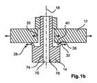
図1Aには、陽極ディスク12、回転シャフト14、及び陽極ディスク支持体16を有する回転陽極アセンブリ10が示されている。また、回転シャフト14の回転軸線18が示されている。陽極ディスク12は、陽極ディスク支持体16を介して回転シャフト14の回転軸線18に同心状に装着される。陽極ディスク支持体16は、回転シャフト14において回転軸線18と同心状に設けられた、第1の円形の軸線方向支持面22を含む支持体20を有する。第1の支持体20及び第1の円形の軸線方向支持面22について、以下でさらに説明する。陽極ディスク支持体16は、クランプ軸線方向に第1の支持面22に対して陽極ディスク12を付勢するために回転シャフト14に少なくとも一時的に装着された、第2の軸線方向支持面26を含む第2の支持体24も有する。図1Bにも示されるように、第1の支持体20は、半径方向に可撓性を有する支持体28として設けられている。
Exemplary embodiments of the invention are described below with reference to the following drawings.
FIG. 1A shows a
図1Bには、陽極ディスク12が、例えばX線発生によって加熱される状況が示されており、陽極ディスクの熱膨張が、熱膨張を示す矢印30で示されるように生じる。半径方向に可撓性を有する支持体28は、曲げ矢印32で示されるように屈曲される。この屈曲は、第1の軸線方向支持面22が、半径方向の、すなわち回転軸線18に対して垂直方向の熱膨張に少なくとも部分的に追従するように、半径方向に生じる。
「陽極ディスク」は、半径方向に平坦な形状を含む円形形態を有するような陽極に関する。陽極ディスクは、このディスクの半径方向が、回転シャフトの回転軸線に対して垂直になるように、回転シャフトに装着される。
FIG. 1B shows a situation in which the
“Anode disk” relates to an anode having a circular form including a radially flat shape. The anode disk is mounted on the rotating shaft such that the radial direction of the disk is perpendicular to the rotation axis of the rotating shaft.
「第1の円形の軸線方向支持面」は、陽極ディスクを装着するための当接面に関し、この当接は、軸線方向で、すなわち回転軸線の方向で行われる。「第2の軸線方向支持面」は、陽極ディスクを装着するための当接面に関しこの当接は、軸線方向で、すなわち回転軸線の方向で行われる。第1の軸線方向支持面及び第2の軸線方向支持面は、陽極ディスクの反対側に配置されており、これら第1の軸線方向支持面と第2の軸線方向支持面との間で回転ディスクをクランプする。換言すると、第1及び第2の軸線方向支持面は、2つの異なる側面から回転ディスクに当接する。
第1の円形の支持面は、第1の相互接続部とも呼称され、及び第2の円形の支持面は、第2の相互接続部とも呼称される。
The “first circular axial support surface” relates to a contact surface for mounting the anode disk, and this contact is performed in the axial direction, that is, in the direction of the rotation axis. The “second axial support surface” relates to the contact surface for mounting the anode disk, and this contact is performed in the axial direction, that is, in the direction of the rotation axis. The first axial support surface and the second axial support surface are disposed on opposite sides of the anode disk, and the rotating disk is between the first axial support surface and the second axial support surface. Clamp. In other words, the first and second axial support surfaces come into contact with the rotating disk from two different side surfaces.
The first circular support surface is also referred to as the first interconnect and the second circular support surface is also referred to as the second interconnect.
実施例では、陽極ディスクには、中心ボア34が設けられている。実施例では、第2の支持体は、中心ボア34を貫通して延びるシャフトの端部36にねじ切りされたナットである。
実施例では、第2の支持体24は、ブッシングである。
更なる実施例では、第2の支持体は、回転シャフト14の端部に溶接された又はろう付けされたクランプ要素によって提供される。
実施例では、第1の支持面は、回転シャフトに一体に形成される、すなわち、単一のピース又は部品として形成される。
図1Bに示される曲げ運動は、説明目的のためだけに、かなり極端な態様で示されていることに留意されたい。実際には、本発明によれば、その変形は、例えば0.5ミリメートル(mm)まで、例えば0.3mm又は0.2mmまでの範囲である。
半径方向に可撓性を有する支持体の屈曲は、弾性変形に限定される。
In the embodiment, the anode disk is provided with a
In the embodiment, the
In a further embodiment, the second support is provided by a clamping element welded or brazed to the end of the
In an embodiment, the first support surface is integrally formed on the rotating shaft, i.e. formed as a single piece or piece.
Note that the bending motion shown in FIG. 1B is shown in a fairly extreme manner for illustrative purposes only. In practice, according to the present invention, the deformation ranges for example up to 0.5 millimeters (mm), for example up to 0.3 mm or 0.2 mm.
The bending of the support having flexibility in the radial direction is limited to elastic deformation.
回転シャフト14上に設けられた第1の支持面22が、図1A及び図1Bに示されている。第1の軸線方向支持面22によって陽極ディスク12の熱膨張が補償され、それによって、熱膨張中に、第1の支持面の第1の接触領域38と陽極ディスク12の第2の接触領域40とが、回転シャフト14に関して及び回転軸線18に関して共に移動し、その接触を維持する。換言すると、接触が維持され、且つ第1及び第2の接触領域との間の摩擦に関する移動が防止される、又は少なくとも最小限に抑えられる。
実施例によれば、図1Aにも示されるように、軸線方向の断面において、第1の支持体20には、半径方向の幅42及び軸線方向の高さ44が設けられており、ここで半径方向幅42は、軸線方向の高さ44よりも小さい。例えば、軸線方向の高さ44は、半径方向の幅42の少なくとも2倍の大きさである。
A
According to the embodiment, as also shown in FIG. 1A, in the axial section, the
図1Aにも示されるように、第1の支持体は、支持体ベースによって回転シャフトに接続されており、ここで支持体ベースには、軸線方向にベースの高さが設けられる。回転シャフト14の底面における表面46から水平方向の表面までの距離であるベースの高さは、第1の支持体の半径方向の幅42よりも大きい。ベースの高さは、半径方向の幅42の少なくとも2倍の大きさである。基準線Xに沿った支持体ベースと回転シャフトとの間の接続は、連続又は分離してもよい。
As also shown in FIG. 1A, the first support member is connected to the support base depending on the rotation shaft, wherein the support base is provided high Saga of the base in the axial direction. Based height from the
別の実施例によれば、オプションとして図1A、図1B及び図1Cに示されるように、第1の支持体20は、回転シャフト上の肩部46から軸線方向に突設されており、オプションとして、この肩部は、回転シャフトの外径の階段状凹部によって形成される。
少なくとも周方向のギャップ48が、陽極ディスク12のボアを貫通して延びるシャフト端部50に設けられている。
例えば、オプションとして図1A及び図1Bに示されるように、第1の支持体20には、陽極ディスク12のボアを貫通して延びるシャフト端部50までの距離52が設けられており、この距離52は、軸線方向の高さ44よりも大きい。
例えば、この距離は、軸線方向の高さ44の少なくとも2倍の大きさである。
According to another embodiment, as shown in FIGS. 1A, 1B and 1C as an option, the
At least a
For example, as shown in FIGS. 1A and 1B as an option, the
For example, this distance is at least twice as large as the
図2Aには、回転陽極アセンブリ10の更なる実施例が示されており、第1の支持体20は、図2Bの水平方向断面で示されるような複数の半径方向に可撓性を有する支持要素54を含む。半径方向に可撓性を有する支持要素によって、複数の第1の軸線方向支持面部分56が設けられる。実施例では、示されるように、半径方向に可撓性を有する支持要素54同士には、互いにギャップ58が設けられている。更なる実施例では、図示しないが、このギャップは、隣接する支持要素が非屈曲状態で側面同士で互いに当接するように、最小限に低減される。
FIG. 2A shows a further embodiment of the
実施例では、半径方向に可撓性を有する支持要素54は、銃眼付きの胸壁(battlement)の設計とも呼ばれる城郭様式で設けられる。
一例として、半径方向に可撓性を有する支持要素は、熱に依存する半径方向に可撓性を有する支持要素として設けられる。
支持要素には、第1の円形の軸線方向支持面と陽極ディスク表面上の対応部分との間の摩擦力を介した陽極の熱膨張によって生じる屈曲を可能にするのに十分であるような可撓性が提供される。その摩擦力は、ナットの締付力によって生じる。支持要素は、適当な装着を可能にするのに十分な剛性を有する。
実施例では、その可撓性は、摩擦力の少なくとも2倍、例えば摩擦力の5倍の大きさである。
In an embodiment, the radially
As an example, the radially flexible support element is provided as a radially flexible support element that depends on heat.
The support element may be such that it is sufficient to allow bending caused by thermal expansion of the anode via frictional forces between the first circular axial support surface and a corresponding portion on the anode disk surface. Flexibility is provided. The frictional force is generated by the tightening force of the nut. The support element has sufficient rigidity to allow proper mounting.
In an embodiment, the flexibility is at least twice as large as the friction force, for example five times as large as the friction force.
実施例によれば、尖塔(pinnacles)とも呼ばれる半径方向に可撓性を有する支持要素は、接触領域での摩擦力によって、尖塔の弾性曲げが十分生じるように寸法決めされる。
実施例では、12個のスリットが、約30°の円形セグメントを形成するように設けられる。
支持面は、2.5mmの幅(h)である。
溝の深さ(l)は、6mmである。
スリットは、4mmの幅を有しており、その結果、b=15mmとなる。
According to an embodiment, the radially flexible support elements, also called pinnacles, are dimensioned so that the elastic bending of the spire is sufficiently caused by the frictional forces in the contact area.
In an embodiment, twelve slits are provided to form a circular segment of about 30 °.
The support surface has a width (h) of 2.5 mm.
The depth (l) of the groove is 6 mm.
The slit has a width of 4 mm, resulting in b = 15 mm.
支持面の半径方向の変位は、次のとおりである。
f=F・l3/3・E・I
断面二次モーメントは、略次のとおりである。
I=b・h3/12
所定の半径方向の変位に必要な摩擦力は、次のとおりである。
F=(b・h3・E/4・l3)・f
第1のアプローチとして、最大の半径方向変位fは:f=0.03mmである。
その結果、要求される摩擦力Fは:F=2.4kNである。
最小摩擦係数μを:μ=0.2と想定すると、要求される押圧力Fnは:Fn=12kNである。
この力は、例えば、ナットを締めることによって提供される。
The radial displacement of the support surface is as follows.
f = F · l 3/3 · E · I
The cross-sectional second moment is substantially as follows.
I = b · h 3/12
The frictional force required for the predetermined radial displacement is as follows.
F = (b · h 3 · E / 4 · l 3 ) · f
As a first approach, the maximum radial displacement f is: f = 0.03 mm.
As a result, the required frictional force F is: F = 2.4 kN.
Assuming that the minimum friction coefficient μ is: μ = 0.2, the required pressing force F n is: F n = 12 kN.
This force is provided, for example, by tightening the nut.
図3Aには、回転シャフト14の肩部62から軸線方向に突出する軸線方向の円形のカラー60を含み、カラー60と回転シャフト14との間の逃げ溝64が設けられた第1の支持体20の更なる実施例が示されている。例えば肩部62は、シャフトの直径の凹部によって半径方向に設けられる。実施例では、この凹部は、回転シャフトの直径に段階形状として設けられる。カラー60が、水平方向断面図、すなわち平面図で図3Bに示されており、カラー60は、円形の支持面66を提供する。カラー60は、簡略化のために可撓性を有する支持要素54と同様の寸法で示されることに留意されたい。実施例では、カラーは、複数の可撓性を有する支持要素54と同様の曲げ運動を可能にするために、より薄い寸法で設けられる。
更なる実施例では、さらに図示しないが、異なる数のセグメント、例えば図3Bの3つのセグメントのカラーが設けられる。
FIG. 3A shows a first support including an axially
In a further embodiment, although not further illustrated, different numbers of segments are provided, for example the colors of the three segments of FIG. 3B.
更なる実施例では、図4に示されるように、熱伝達要素68が、回転シャフトを介した熱伝導のために半径方向に可撓性を有する支持体と回転シャフトとの間に設けられる。実施例では、熱伝達要素は、熱伝導性液体、例えば可撓性を有する支持要素の場合には可撓性エンベロープ内の液体を含む。連続的なカラーの場合には、その液体は、エンベロープなしで提供してもよい。
In a further embodiment, a
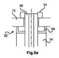
図5Aには、第1の支持体20が、別個の構成要素として、例えば中心部の両側にL字状の断面69を有し、回転シャフトの延出部が貫通して延びるボアを有するディスク20’として提供される更なる実施例が示されている。別個の構成要素は、例えば回転シャフトを取り囲む正確に嵌合するボアによって回転シャフトに固定して取り付けられる。換言すれば、第1の支持体は、カラーを提供するようなU字状の断面のブッシングとして設けられており、このブッシングは、第1の円形の軸線方向支持面を提供する。別個の部品の場合には、軸線方向の支持面の基点が、回転軸線に対して半径方向に固定して設けられていることに注意しなければならない。
In FIG. 5A, the
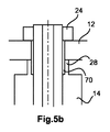
図5Bには、半径方向に可撓性を有する支持体28には、回転シャフト14の隣接する部分に小さなギャップ70が設けられた更なる実施例が示されている。
図5Cには、第1の支持体20の半径方向に可撓性を有する支持体28に加えて、第2の支持体24には、第2の円形の軸線方向支持面72が設けられており、半径方向に可撓性を有する支持体として設けられた更なる実施例が示されている。X線発生中の陽極ディスクを加熱する際であって、陽極ディスク12が熱膨張する際に、第1の支持体20の半径方向に可撓性を有する支持体だけでなく第2の支持体24の半径方向に可撓性を有する支持体は、半径方向に屈曲し、それによって、第1の軸線方向支持面と第2の軸線方向支持面が、半径方向の熱膨張に少なくとも部分的に追従する(さらに図示せず)。
FIG. 5B shows a further embodiment in which the radially
In FIG. 5C, in addition to the
図6には、X線用真空ハウジング102、陽極104、及び陰極106を有するX線管100が示されている。X線用真空ハウジング102内でX線透過窓112を通って放射されるX線放射110を発生するような電子ビーム108が概略的に示されている。陽極104及び陰極106は、X線用真空ハウジング102の内部に配置される。陽極104は、陽極シャフト116に装着された陽極ディスク114と一緒に示されている。また、回転軸線18の周りを回転する回転陽極114を駆動するための駆動機構118が、概略的に示されている。更なる構成要素が設けられるが、図示していない。さらに、詳細に図示していないが、陽極を支持する軸受装置が設けられており、この軸受装置は、参照符号120で示されている。
FIG. 6 shows an
本発明によれば、陽極104は、上述した実施例のいずれかに係る回転陽極アセンブリ10として設けられる。軸受装置120は、回転シャフト14、116を支持するX線用真空ハウジング102の内側に配置される。軸受装置は、少なくとも1つの螺旋溝軸受を有する(さらに図示しない)。
実施例によれば、図1〜図5に示されるように、回転シャフト14には、中空のボア74が設けられており、固定シャフト76が、ボア74の内部に設けられ、螺旋溝軸受装置78で支持される。
According to the present invention, the
According to the embodiment, as shown in FIGS. 1 to 5, the
図7には、X線撮像システム200の一例が示されており、このX線撮像システムは、X線源204及びX線検出器206を含むX線取得装置202を有する。また、対象物支持体208が設けられている。対象物支持体208は、X線源204によって提供される扇形構造212で示されるX線を対象物、例えば患者210に照射するために、X線源204とX線検出器206との間に配置される。X線源204は、上述した実施例に係るX線管100を有する。
X線撮像システム200は、概略的に示されるガントリ214を有するCT装置として示されていることに留意されたい。また、処理装置216は、表示装置220とも組み合わせて、データ接続218される。
CT装置の代わりに、他のX線撮像システム、例えば対象物支持体に関してX線源を固定した構成のX線撮像システム又はCアームシステムも提供される。
FIG. 7 shows an example of an
Note that the
In place of the CT apparatus, another X-ray imaging system, for example, an X-ray imaging system or a C-arm system configured to fix the X-ray source with respect to the object support is also provided.
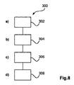
図8には、回転陽極ディスクを装着するための方法300が示されており、この方法は、以下のステップを含む。
第1のステップ302では、陽極ディスク支持体の第1の支持体が、回転シャフトにおいて、このシャフトの回転軸線に対して垂直に設けられる。第1の支持体は、回転シャフトにおいて、回転軸線の周りに同心状に設けられた第1の軸線方向支持面を含む。
第2のステップ304では、陽極ディスクが設けられる。
第3のステップ306では、陽極ディスク支持体の第2の支持体が設けられ、第2の支持体は、第2の軸線方向支持面を含む。
FIG. 8 shows a
In a
In the
In a
第4のステップ308では、第2の支持体は、クランプ軸線方向に第1の支持体に対して陽極ディスクを付勢するために、回転シャフトに少なくとも一時的に装着される。第1の支持体は、半径方向に可撓性を有する支持体として設けられており、X線発生中の陽極ディスクを加熱する際に、この半径方向に可撓性を有する支持体は、半径方向に屈曲し、それによって、第1の軸線方向支持面は、陽極ディスクの半径方向の熱膨張に少なくとも部分的に追従する。
第1のステップ302はステップa)とも呼称され、第2のステップ304はステップb)とも呼称され、第3のステップ306はステップc)とも呼称され、第4ステップ308はステップd)とも呼称される。
更なる実施例によれば、陽極ディスクを回転シャフトに装着するためのX線管における支持体の使用も提供される(さらに図示しない)。
In a
The
According to a further embodiment, the use of a support in an X-ray tube for attaching the anode disk to the rotating shaft is also provided (further not shown).
なお、本発明の実施形態は、様々な主題を参照して説明していることに留意されたい。特に、いくつかの実施形態は、方法タイプクレームを参照して説明しているが、他の実施形態は、装置タイプクレームを参照して説明している。しかしながら、当業者は、特に断らない限り、1つのタイプの主題に属する特徴の任意の組合せに加えて、異なる主題に関する特徴同士間の任意の組合せも本願に開示されているとみなすことを、上記及び以下の詳細な説明から推量するだろう。しかしながら、全ての特徴は、特徴の単純な総和よりも大きな相乗効果を提供するように組み合わせることができる。 It should be noted that embodiments of the present invention have been described with reference to various subject matters. In particular, some embodiments have been described with reference to method type claims, while other embodiments have been described with reference to apparatus type claims. However, those skilled in the art will recognize that any combination between features on different subjects is considered to be disclosed in this application in addition to any combination of features belonging to one type of subject matter, unless otherwise specified. And will be inferred from the detailed description below. However, all features can be combined to provide a greater synergy than a simple sum of features.
本発明について、図面及び前述した詳細な説明において詳細に図示及び説明してきたが、このような図示及び説明は、例又は例示としてみなすべきであり、限定的なものとしてみなすべきでない。本発明は、開示された実施形態に限定されるものではない。開示された実施例に対する他の変形形態は、図面、明細書の開示、及び従属請求項の検討から、特許請求の範囲に記載された発明を実施する際に当業者によって理解され、達成することができる。 Although the invention has been illustrated and described in detail in the drawings and foregoing detailed description, such illustration and description are to be considered illustrative or exemplary and not restrictive. The invention is not limited to the disclosed embodiments. Other variations to the disclosed embodiments will be understood and attained by those skilled in the art in practicing the claimed invention, from a study of the drawings, the disclosure of the specification, and the dependent claims. Can do.
特許請求の範囲において、「備える、有する、含む(comprising)」という用語は、他の要素又はステップを除外するものではなく、不定冠詞「1つの(a, an)」は、複数を排除するものではない。単一のプロセッサ又は他のユニットは、特許請求の範囲に記載されるいくつかのアイテムの機能を充足することができる。特定の手段が互いに異なる従属請求項に記載されているという単なる事実は、これら手段の組合せが有利に使用できないことを示すものではない。請求項における任意の参照符号は、特許請求の範囲を限定するものとしてみなすべきではない。 In the claims, the term “comprising” does not exclude other elements or steps, and the indefinite article “a, an” excludes the plural. is not. A single processor or other unit may fulfill the functions of several items recited in the claims. The mere fact that certain measures are recited in mutually different dependent claims does not indicate that a combination of these measured cannot be used to advantage. Any reference signs in the claims should not be construed as limiting the scope.
Claims (14)
ボアを有する陽極ディスクと;
回転シャフトと;
陽極ディスク支持体と;を備えており、
前記陽極ディスクは、前記陽極ディスク支持体を介して前記回転シャフトの回転軸線に同心状に装着され、
前記陽極ディスク支持体は、前記回転シャフトにおいて前記回転軸線と同心状に設けられた、第1の円形の軸線方向支持面を含む第1の支持体を有し、
前記陽極ディスク支持体は、クランプ軸線方向に第1の支持面に対して前記陽極ディスクを付勢するために前記回転シャフトに少なくとも一時的に装着された、第2の軸線方向支持面を含む第2の支持体を有し、
第1の支持体は、半径方向に可撓性を有する支持体として設けられており、
X線発生中の前記陽極ディスクを加熱する際であって、前記陽極ディスクが熱膨張する際に、前記半径方向に可撓性を有する支持体は、半径方向に屈曲し、それによって、第1の軸線方向支持面が、半径方向の熱膨張に少なくとも部分的に追従し、
第1の支持体は、前記半径方向よりも前記軸線方向の力に対してより大きな抵抗を有しており、
第1の支持体は、支持体ベースによって前記回転シャフトに接続されており、前記支持体ベースには、前記軸線方向にベースの高さが設けられており、前記ベースの高さは、第1の支持体の前記半径方向の幅の少なくとも2倍であり、
軸線方向の断面において、第1の支持体には、半径方向の幅と軸線方向の高さとが設けられており、該軸線方向の高さは、前記半径方向の幅の少なくとも2倍である、
回転陽極アセンブリ。 A rotating anode assembly comprising:
An anode disk having a bore ;
A rotating shaft;
An anode disk support; and
The anode disk is mounted concentrically on the rotation axis of the rotating shaft via the anode disk support,
The anode disk support has a first support including a first circular axial support surface provided concentrically with the rotation axis on the rotating shaft;
The anode disk support includes a second axial support surface that is at least temporarily mounted to the rotating shaft to bias the anode disk against the first support surface in a clamping axis direction. Having two supports,
The first support is provided as a support having flexibility in the radial direction,
When the anode disk during X-ray generation is heated and the anode disk thermally expands, the support having flexibility in the radial direction is bent in the radial direction, whereby the first disk axial support surface of at least partially follow the thermal expansion in the radial direction,
The first support has a greater resistance to force in the axial direction than in the radial direction;
The first support is connected to the rotating shaft by a support base, and the support base is provided with a base height in the axial direction. At least twice the radial width of the support of
In the axial cross section, the first support is provided with a radial width and an axial height, the axial height being at least twice the radial width.
Rotating anode assembly.
第1の軸線方向支持面によって前記陽極ディスクの熱膨張が補償され、それによって、前記熱膨張中に、第1の支持面の第1の接触領域と前記陽極ディスクの第2の接触領域とが、前記回転軸線に関して共に移動し、その接触が維持される、
請求項1に記載の回転陽極アセンブリ。 The first support surface is provided on the rotating shaft,
A first axial support surface compensates for thermal expansion of the anode disk, so that during the thermal expansion, the first contact area of the first support surface and the second contact area of the anode disk are Move together with respect to the axis of rotation and maintain contact therewith,
The rotating anode assembly according to claim 1 .
少なくとも周方向のラジアルギャップが、前記陽極ディスクの前記ボアを貫通して延びるシャフト端部に設けられる、
請求項1に記載の回転陽極アセンブリ。 The first support is protruded in the axial direction from the shoulder of the rotary shaft,
Radial gap of at least the circumferential direction is provided in the shaft end portion extending through said bore of said anode disk,
The rotating anode assembly according to claim 1 .
請求項3に記載の回転陽極アセンブリ。 The shoulder portion is formed by a stepped recess having an outer diameter of the rotating shaft.
The rotating anode assembly according to claim 3 .
請求項1に記載の回転陽極アセンブリ。 The first support, the are distance is provided to the shaft end portion extending through the bore of the anode disk, said distance is greater than the height of the axial,
The rotating anode assembly according to claim 1 .
請求項1に記載の回転陽極アセンブリ。 The first support includes an axial circular collar protruding in an axial direction from a shoulder portion of the rotary shaft, and a relief groove is provided between the collar and the rotary shaft.
The rotating anode assembly according to claim 1 .
請求項1に記載の回転陽極アセンブリ。 The first support includes a plurality of radially flexible support elements that provide a plurality of first axial support surface portions.
The rotating anode assembly according to claim 1 .
請求項7に記載の回転陽極アセンブリ。 For heat conduction through the rotating shaft, a heat transfer element is provided between the rotating shaft and the flexible support in the radial direction.
The rotating anode assembly according to claim 7 .
第2の支持体は、半径方向に可撓性を有する支持体として設けられており、
X線発生中の前記陽極ディスクを加熱する際であって、前記陽極ディスクが熱膨張する際に、第2の支持体の半径方向に可撓性を有する支持体は、半径方向に曲がり、それによって、第2の軸線方向支持面は、半径方向の熱膨張に少なくとも部分的に追従する、
請求項8に記載の回転陽極アセンブリ。 The second support includes a second circular axial support surface;
The second support is provided as a support having flexibility in the radial direction,
When the anode disk during X-ray generation is heated and the anode disk is thermally expanded, the support body having flexibility in the radial direction of the second support body is bent in the radial direction. The second axial support surface at least partially follows the radial thermal expansion,
The rotating anode assembly according to claim 8 .
X線用真空ハウジングと;
陽極と;
陰極と;
前記陽極を支持するための軸受装置と;を備えており、
前記陽極及び前記陰極は、前記X線用真空ハウジングの内部に配置され、
前記陽極は、請求項1に記載の回転陽極アセンブリとして設けられ、
前記軸受装置は、前記X線用真空ハウジングの内部に配置され、前記回転シャフトを支持し、
前記軸受装置は、少なくとも1つの螺旋溝軸受を含む、
X線管。 An x-ray tube, which is:
A vacuum housing for X-rays;
With the anode;
A cathode;
A bearing device for supporting the anode; and
The anode and the cathode are disposed inside the X-ray vacuum housing,
The anode is provided as a rotating anode assembly according to claim 1 ,
The bearing device is disposed inside the vacuum housing for X-rays, supports the rotating shaft,
The bearing device includes at least one helical groove bearing,
X-ray tube.
固定シャフトが、ボアの内部に設けられ、前記回転シャフトを支持し、
前記回転シャフトは、前記固定シャフトによって、少なくとも1つの螺旋溝軸受で支持される、
請求項10に記載のX線管。 The rotating shaft is provided with a hollow bore,
A fixed shaft is provided inside the bore and supports the rotating shaft;
The rotary shaft, by the fixed shaft is supported by at least one spiral groove bearings,
The X-ray tube according to claim 10 .
X線源及びX線検出器を含むX線取得装置と;
対象物支持体と;を備えており、
前記対象物支持体は、前記X線源によって供給されるX線を対象物に照射するために、前記X線源と前記X線検出器との間に配置されており、
前記X線源は、請求項10に記載のX線管を含む、
X線撮像システム。 An X-ray imaging system, which is:
An X-ray acquisition device including an X-ray source and an X-ray detector;
An object support; and
The object support is disposed between the X-ray source and the X-ray detector to irradiate the object with X-rays supplied by the X-ray source;
The X-ray source includes the X-ray tube according to claim 10 ,
X-ray imaging system.
a)陽極ディスク支持体の第1の支持体を、回転シャフトにおいて、該回転シャフトの回転軸線に対して垂直に設けるステップであって、第1の支持体は、前記回転シャフトにおいて、前記回転軸線の周りに同心状に設けられた第1の軸線方向支持面を含む、設けるステップと;
b)陽極ディスクを設けるステップと;
c)前記陽極ディスク支持体の第2の支持体を設けるステップであって、第2の支持体は、第2の軸線方向支持面を含む、設けるステップと;
d)クランプ軸線方向に第1の支持体に対して前記陽極ディスクを付勢するために、第2の支持体を前記回転シャフトに少なくとも一時的に装着するステップと;を含み、
第1の支持体は、半径方向に可撓性を有する支持体として設けられており、
X線発生中の前記陽極ディスクを加熱する際に、前記半径方向に可撓性を有する支持体は、半径方向に屈曲し、それによって、第1の軸線方向支持面は、前記陽極ディスクの半径方向の熱膨張に少なくとも部分的に追従し、
第1の支持体は、前記半径方向よりも前記軸線方向の力に対してより大きな抵抗を有しており、
第1の支持体は、支持体ベースによって前記回転シャフトに接続されており、前記支持体ベースには、前記軸線方向にベースの高さが設けられており、前記ベースの高さは、第1の支持体の前記半径方向の幅の少なくとも2倍であり、
軸線方向の断面において、第1の支持体には、半径方向の幅と軸線方向の高さとが設けられており、該軸線方向の高さは、前記半径方向の幅の少なくとも2倍である、
方法。 A method for mounting a rotating anode disk, the method comprising:
a) providing a first support for the anode disk support on the rotary shaft perpendicular to the rotational axis of the rotary shaft, wherein the first support is the rotational axis on the rotary shaft; Providing a first axial support surface concentrically disposed around the surface;
b) providing an anode disk;
c) providing a second support of the anode disk support, wherein the second support includes a second axial support surface;
d) at least temporarily mounting a second support to the rotating shaft to bias the anode disk against the first support in a clamping axis direction;
The first support is provided as a support having flexibility in the radial direction,
When heating the anode disk during X-ray generation, the radially flexible support bends in the radial direction so that the first axial support surface is the radius of the anode disk. at least partially follows the direction of thermal expansion,
The first support has a greater resistance to force in the axial direction than in the radial direction;
The first support is connected to the rotating shaft by a support base, and the support base is provided with a base height in the axial direction. At least twice the radial width of the support of
In the axial cross section, the first support is provided with a radial width and an axial height, the axial height being at least twice the radial width.
Method.
前記支持体は、回転シャフトにおいて、回転軸線の周りに同心状に設けられた、第1の軸線方向支持面を含む第1の支持体を有し、
第2の軸線方向支持面を含む第2の支持体が設けられており、第2の支持体は、クランプ軸線方向に第1の支持体に対して陽極ディスクを付勢するために、前記回転シャフトに少なくとも一時的に装着され、
第1の支持体は、半径方向に可撓性を有する支持体として設けられており、X線発生中の前記陽極ディスクを加熱する際に、前記半径方向に可撓性を有する支持体は、半径方向に屈曲し、それによって、第1の軸線方向支持面は、前記陽極ディスクの半径方向の熱膨張に少なくとも部分的に追従し、
第1の支持体は、前記半径方向よりも前記軸線方向の力に対してより大きな抵抗を有しており、
第1の支持体は、支持体ベースによって前記回転シャフトに接続されており、前記支持体ベースには、前記軸線方向にベースの高さが設けられており、前記ベースの高さは、第1の支持体の前記半径方向の幅の少なくとも2倍であり、
軸線方向の断面において、第1の支持体には、半径方向の幅と軸線方向の高さとが設けられており、該軸線方向の高さは、前記半径方向の幅の少なくとも2倍である、
使用。 Use of a support in an X-ray tube for mounting an anode disk to a rotating shaft:
The support includes a first support including a first axial support surface provided concentrically around the rotation axis in the rotation shaft;
A second support is provided that includes a second axial support surface, the second support rotating to rotate the anode disk against the first support in the clamp axis direction. Attached at least temporarily to the shaft,
The first support is provided as a support having flexibility in the radial direction, and when the anode disk during X-ray generation is heated, the support having flexibility in the radial direction is: bent radially, whereby a first axial support surface at least partially follow the radial thermal expansion of the anode disc,
The first support has a greater resistance to force in the axial direction than in the radial direction;
The first support is connected to the rotating shaft by a support base, and the support base is provided with a base height in the axial direction. At least twice the radial width of the support of
In the axial cross section, the first support is provided with a radial width and an axial height, the axial height being at least twice the radial width.
use.
Applications Claiming Priority (3)
| Application Number | Priority Date | Filing Date | Title |
|---|---|---|---|
| EP13176026.6 | 2013-07-11 | ||
| EP13176026 | 2013-07-11 | ||
| PCT/EP2014/063013 WO2015003886A1 (en) | 2013-07-11 | 2014-06-20 | Rotating anode mount adaptive to thermal expansion |
Publications (3)
| Publication Number | Publication Date |
|---|---|
| JP2016526775A JP2016526775A (en) | 2016-09-05 |
| JP2016526775A5 JP2016526775A5 (en) | 2018-02-01 |
| JP6318245B2 true JP6318245B2 (en) | 2018-04-25 |
Family
ID=48748059
Family Applications (1)
| Application Number | Title | Priority Date | Filing Date |
|---|---|---|---|
| JP2016524721A Active JP6318245B2 (en) | 2013-07-11 | 2014-06-20 | Installation of rotating anode suitable for thermal expansion |
Country Status (5)
| Country | Link |
|---|---|
| US (2) | US9934931B2 (en) |
| EP (1) | EP3020061B1 (en) |
| JP (1) | JP6318245B2 (en) |
| CN (1) | CN105378890B (en) |
| WO (1) | WO2015003886A1 (en) |
Families Citing this family (1)
| Publication number | Priority date | Publication date | Assignee | Title |
|---|---|---|---|---|
| CN104810229B (en) * | 2015-04-16 | 2017-01-18 | 赛诺威盛科技(北京)有限公司 | X-ray tube using piezoelectric ceramic for positive electrode movement compensation and compensation method thereof |
Family Cites Families (13)
| Publication number | Priority date | Publication date | Assignee | Title |
|---|---|---|---|---|
| JPS553181A (en) * | 1978-06-23 | 1980-01-10 | Toshiba Corp | Rotary anode structure for x-ray tube |
| CS232586B1 (en) | 1983-03-31 | 1985-02-14 | Frantisek Starek | Seating of rotating parts of a x-ray tube's anode |
| JPS61198537A (en) | 1985-02-27 | 1986-09-02 | Hitachi Medical Corp | X-ray tube with rotary anode |
| US4736400A (en) * | 1986-01-09 | 1988-04-05 | The Machlett Laboratories, Inc. | Diffusion bonded x-ray target |
| JP2581923Y2 (en) | 1992-11-30 | 1998-09-24 | 株式会社島津製作所 | Rotating anode X-ray tube |
| WO2003019610A1 (en) | 2001-08-29 | 2003-03-06 | Kabushiki Kaisha Toshiba | Rotary positive pole type x-ray tube |
| AU2003201153A1 (en) | 2002-02-11 | 2003-09-04 | Koninklijke Philips Electronics N.V. | A device for generating x-rays |
| FR2846784B1 (en) | 2002-10-30 | 2005-02-11 | Ge Med Sys Global Tech Co Llc | BEARING ASSEMBLY FOR ROTATING MOUNTING OF ROTARY ANODE OF X-RAY TRANSMITTING DEVICE AND X-RAY TRANSMITTING DEVICE EQUIPPED WITH SUCH AN ASSEMBLY |
| US7184520B1 (en) * | 2003-01-29 | 2007-02-27 | Varian Medical Systems Technologies, Inc. | Component mounting system with stress compensation |
| CN1868026A (en) * | 2003-10-17 | 2006-11-22 | 株式会社东芝 | X-ray apparatus |
| US8111025B2 (en) | 2007-10-12 | 2012-02-07 | Varian Medical Systems, Inc. | Charged particle accelerators, radiation sources, systems, and methods |
| JP5529152B2 (en) | 2008-11-26 | 2014-06-25 | コーニンクレッカ フィリップス エヌ ヴェ | X-ray tube with rotatable anode and liquid heat sink |
| JP5646876B2 (en) * | 2010-05-13 | 2014-12-24 | 株式会社日立メディコ | Rotating anode X-ray tube and X-ray tube apparatus having the same |
-
2014
- 2014-06-20 JP JP2016524721A patent/JP6318245B2/en active Active
- 2014-06-20 US US14/903,805 patent/US9934931B2/en active Active
- 2014-06-20 WO PCT/EP2014/063013 patent/WO2015003886A1/en active Application Filing
- 2014-06-20 EP EP14738419.2A patent/EP3020061B1/en active Active
- 2014-06-20 CN CN201480039451.4A patent/CN105378890B/en active Active
-
2018
- 2018-02-22 US US15/902,416 patent/US20180182591A1/en not_active Abandoned
Also Published As
| Publication number | Publication date |
|---|---|
| US20180182591A1 (en) | 2018-06-28 |
| US20160163498A1 (en) | 2016-06-09 |
| US9934931B2 (en) | 2018-04-03 |
| CN105378890A (en) | 2016-03-02 |
| CN105378890B (en) | 2018-07-10 |
| EP3020061A1 (en) | 2016-05-18 |
| WO2015003886A1 (en) | 2015-01-15 |
| EP3020061B1 (en) | 2020-03-11 |
| JP2016526775A (en) | 2016-09-05 |
Similar Documents
| Publication | Publication Date | Title |
|---|---|---|
| US8553844B2 (en) | Hybrid design of an anode disk structure for high prower X-ray tube configurations of the rotary-anode type | |
| JP7214336B2 (en) | Systems and methods for reducing relative bearing shaft deflection in x-ray tubes | |
| JP6318245B2 (en) | Installation of rotating anode suitable for thermal expansion | |
| US10504679B2 (en) | X-ray generating apparatus and radiography system including the same | |
| US6888923B2 (en) | Assembly for mounting a radiation emitting device, radiation emitting device having such an assembly, and a radiological apparatus having such an assembly and emitting device | |
| JP2017091881A (en) | X-ray tube apparatus and X-ray CT apparatus | |
| JP6169576B2 (en) | Rotating anode type X-ray tube apparatus and X-ray imaging apparatus | |
| US11920630B2 (en) | Self-lubricated sliding bearing | |
| JP5890309B2 (en) | X-ray tube apparatus and X-ray CT apparatus | |
| JP6304986B2 (en) | Breast tomography equipment | |
| JP6416593B2 (en) | Rotating anode X-ray tube device and X-ray imaging device | |
| JP2016526775A5 (en) | ||
| JP5566062B2 (en) | X-ray tube apparatus and X-ray imaging apparatus | |
| JP5959866B2 (en) | X-ray tube apparatus and X-ray CT apparatus | |
| JP6798941B2 (en) | X-ray tube device and X-ray CT device | |
| JP2010277822A (en) | X-ray tube device | |
| WO2023228430A1 (en) | Rotary positive electrode x-ray tube | |
| JP2022040843A (en) | X-ray tube device and x-ray imaging device | |
| JP2007220353A (en) | Rotating anode type x-ray tube | |
| CN115376871A (en) | X-ray tube and X-ray generating device | |
| JP2004063444A (en) | X-ray tube device and x-ray ct (computed tomography) device using it | |
| JP2012123931A (en) | Mounting tool, rotary anode x-ray tube device and x-ray device |
Legal Events
| Date | Code | Title | Description |
|---|---|---|---|
| A621 | Written request for application examination |
Free format text: JAPANESE INTERMEDIATE CODE: A621 Effective date: 20170615 |
|
| A521 | Request for written amendment filed |
Free format text: JAPANESE INTERMEDIATE CODE: A523 Effective date: 20171213 |
|
| A871 | Explanation of circumstances concerning accelerated examination |
Free format text: JAPANESE INTERMEDIATE CODE: A871 Effective date: 20171213 |
|
| A975 | Report on accelerated examination |
Free format text: JAPANESE INTERMEDIATE CODE: A971005 Effective date: 20180228 |
|
| TRDD | Decision of grant or rejection written | ||
| A977 | Report on retrieval |
Free format text: JAPANESE INTERMEDIATE CODE: A971007 Effective date: 20180228 |
|
| A01 | Written decision to grant a patent or to grant a registration (utility model) |
Free format text: JAPANESE INTERMEDIATE CODE: A01 Effective date: 20180306 |
|
| A61 | First payment of annual fees (during grant procedure) |
Free format text: JAPANESE INTERMEDIATE CODE: A61 Effective date: 20180402 |
|
| R150 | Certificate of patent or registration of utility model |
Ref document number: 6318245 Country of ref document: JP Free format text: JAPANESE INTERMEDIATE CODE: R150 |
|
| R250 | Receipt of annual fees |
Free format text: JAPANESE INTERMEDIATE CODE: R250 |
|
| R250 | Receipt of annual fees |
Free format text: JAPANESE INTERMEDIATE CODE: R250 |
|
| R250 | Receipt of annual fees |
Free format text: JAPANESE INTERMEDIATE CODE: R250 |
|
| R250 | Receipt of annual fees |
Free format text: JAPANESE INTERMEDIATE CODE: R250 |