JP6315552B2 - Power system protection system and power system protection method - Google Patents
Power system protection system and power system protection method Download PDFInfo
- Publication number
- JP6315552B2 JP6315552B2 JP2014013698A JP2014013698A JP6315552B2 JP 6315552 B2 JP6315552 B2 JP 6315552B2 JP 2014013698 A JP2014013698 A JP 2014013698A JP 2014013698 A JP2014013698 A JP 2014013698A JP 6315552 B2 JP6315552 B2 JP 6315552B2
- Authority
- JP
- Japan
- Prior art keywords
- protection
- power system
- amount
- electricity
- section
- Prior art date
- Legal status (The legal status is an assumption and is not a legal conclusion. Google has not performed a legal analysis and makes no representation as to the accuracy of the status listed.)
- Active
Links
- 238000000034 method Methods 0.000 title claims description 15
- 230000005611 electricity Effects 0.000 claims description 86
- 238000004364 calculation method Methods 0.000 claims description 71
- 238000012545 processing Methods 0.000 claims description 20
- 230000008569 process Effects 0.000 claims description 5
- 230000008859 change Effects 0.000 claims description 2
- 230000005540 biological transmission Effects 0.000 description 52
- 230000004044 response Effects 0.000 description 6
- 230000000903 blocking effect Effects 0.000 description 5
- 238000001514 detection method Methods 0.000 description 5
- 238000010586 diagram Methods 0.000 description 5
- 238000004891 communication Methods 0.000 description 4
- 238000005070 sampling Methods 0.000 description 3
- 206010039203 Road traffic accident Diseases 0.000 description 2
- 230000000694 effects Effects 0.000 description 2
- 230000008030 elimination Effects 0.000 description 2
- 238000003379 elimination reaction Methods 0.000 description 2
- 238000005516 engineering process Methods 0.000 description 2
- 241000255777 Lepidoptera Species 0.000 description 1
- 238000012790 confirmation Methods 0.000 description 1
- 230000001934 delay Effects 0.000 description 1
- 230000003111 delayed effect Effects 0.000 description 1
- 230000006872 improvement Effects 0.000 description 1
- 230000007257 malfunction Effects 0.000 description 1
- 238000012986 modification Methods 0.000 description 1
- 230000004048 modification Effects 0.000 description 1
- 239000013307 optical fiber Substances 0.000 description 1
- 230000001681 protective effect Effects 0.000 description 1
- 238000009420 retrofitting Methods 0.000 description 1
- 230000035945 sensitivity Effects 0.000 description 1
Images


Landscapes
- Emergency Protection Circuit Devices (AREA)
Description
本発明は、電力系統を広域に亘って保護するための電力系統の保護システム及び電力系統の保護方法に関する。 The present invention relates to a power system protection system and a power system protection method for protecting a power system over a wide area.
電力の安定供給に不可欠な電力系統の保護システムは、最近のマイクロプロセッサ技術や情報通信技術を活用したものが主流になっている。例えば、送電線保護リレーについては、デジタル通信回線と組合せた高性能なデジタル電流差動リレーの適用が多数を占めている。電流差動方式は、遮断器で区分された送電線全端子の電流値を常時計測し、それをマイクロ波や光ファイバ通信回線を用いて端子間で相互に交換し合って、差動演算による事故判定を行うものである。 Power system protection systems that are indispensable for the stable supply of power are mainly based on recent microprocessor technology and information communication technology. For example, for power transmission line protection relays, many applications are high-performance digital current differential relays combined with digital communication lines. In the current differential method, the current values of all terminals of the transmission line divided by the circuit breaker are constantly measured, and exchanged between the terminals using microwaves or optical fiber communication lines, and differential operation is performed. Accident judgment is performed.
送電線全端子の電流値を常時計測し、差動演算による事故判定を行う方式においては、全端子の電流を瞬時値レベルで同時にサンプリングする必要がある。電流差動リレーでは、電流値のサンプリングタイミングを全端子にわたって同期(サンプリング同期)化するため、専用の通信回線で電流値データとともにサンプリングタイミングの同期化制御信号を端子間でやり取りしている。 In a method in which current values at all terminals of a transmission line are constantly measured and an accident is determined by differential calculation, it is necessary to simultaneously sample currents at all terminals at an instantaneous value level. In the current differential relay, in order to synchronize the sampling timing of the current value over all the terminals (sampling synchronization), a sampling timing synchronization control signal is exchanged between the terminals together with the current value data through a dedicated communication line.
一方、主保護装置不動作時のバックアップを行う後備保護リレーについては、自端の情報のみで事故の検出・除去を行う距離リレーが多く適用されている。しかし、距離リレーによる後備保護は、時間協調を考慮して事故除去時間を遅く設定する必要が生じる場合や、系統の分流誤差や負荷電流の影響によって保護能力の低下する場合など、事故除去時間の高速化や事故区間の選択性に課題がある。 On the other hand, as relay protection relays that perform backup when the main protection device is not operating, many distance relays that detect and remove accidents using only local information are often used. However, retrofitting protection with distance relays requires less time for accident elimination, such as when it is necessary to set the accident elimination time later in consideration of time coordination, or when the protection capability is reduced due to the effects of system shunt error or load current. There is a problem in speeding up and selectivity of the accident section.
事故除去時間が遅れるケースとしては、長距離送電線と短距離送電線が混在する系統で、長距離送電線の対向母線事故を検出する目的の後備保護第2段距離リレーが短距離線路の対向母線事故までを検出する整定値となる場合があり、短距離線路の後備保護リレーと協調が取り難く、長距離送電線の後備保護第2段の動作を遅延する必要がでてくる。このため、近年では、動作時間の遅延やルート断および運用の煩雑さをなくす目的で、後備保護方式や、従来の遮断器不動作対策の向上策として広域保護装置などが考えられている。 A case where the accident removal time is delayed is a system in which long-distance transmission lines and short-distance transmission lines are mixed, and the second stage distance relay for the purpose of detecting the opposite bus accident of the long-distance transmission line is opposed to the short-distance line. There may be a settling value for detecting up to the bus accident, and it is difficult to coordinate with the rear-end protection relay of the short-distance line, and it is necessary to delay the operation of the rear-end protection second stage of the long-distance transmission line. For this reason, in recent years, for the purpose of eliminating delays in operation time, route disconnection, and complexity of operation, a backup protection system, a wide area protection device, and the like have been considered as an improvement measure for conventional measures for circuit breaker malfunction.
上記のような従来例においては、いずれも、事故除去時間の高速化、遮断器不動作時の対策などについて、個別に性能を向上することは可能である。しかしながら、総合的な性能を考慮した場合、高速・高感度で事故を検出し、最小区間で事故除去を行う主保護機能を持ちながら、しかも、広域の電力系統に亘って総合的な保護機能を有するシステムを実現するものではない。 In any of the conventional examples as described above, it is possible to individually improve the performance for speeding up the accident removal time, countermeasures when the circuit breaker does not operate, and the like. However, when considering the overall performance, it has a main protection function that detects accidents at high speed and with high sensitivity, and eliminates accidents in the minimum section, while providing comprehensive protection functions over a wide-area power system. It does not realize the system that has it.
本発明の目的は、既存システムで実現されてきた主保護機能を有し、主保護機能が作動後、差動演算範囲を拡大し保護機能を作動させる。これにより、最小区間で即時に除去可能であり、広域の電力系統に亘って総合的な保護機能を有する優れた広域保護システムとその方法を提供することである。 An object of the present invention is to have a main protection function that has been realized in an existing system, and after the main protection function is activated, the differential operation range is expanded to activate the protection function. Accordingly, it is an object of the present invention to provide an excellent wide area protection system and method that can be removed immediately in a minimum section and have a comprehensive protection function over a wide area power system.
本発明の電力系統の保護システムは、上記の目的を達成するために、電力系統内の電気量を用いて電力系統の事故区間を判別し、事故区間に応じた遮断器を動作せしめる電力系統の保護システムにおいて、前記保護システムは、事故区間に応じた遮断器へ遮断指令を出力する複数の端末装置と、前記端末間で情報を伝達するためのネットワークと、前記ネットワークに接続し、前記端末装置に保護演算に使用する電気量データを指定する使用電気量の取得箇所を指示する演算装置を備え、前記端末装置は、前記電力系統内の電気量データを取得する電気量取得部と、取得した前記電力系統内の電気量データを記憶する電気量記憶部と、前記電気量記憶部に記憶された電気量データと前記演算装置からの使用電気量に基づいて保護演算を行う保護演算部を備えることを特徴とする。 In order to achieve the above object, the power system protection system according to the present invention uses a quantity of electricity in the power system to determine a fault section of the power system and operates a circuit breaker corresponding to the fault section. In the protection system, the protection system includes a plurality of terminal devices that output a break command to a circuit breaker corresponding to an accident section, a network for transmitting information between the terminals, and the terminal device connected to the network. A calculation device for designating an acquisition point of the amount of electricity used for specifying the amount of electricity to be used for the protection calculation, and the terminal device acquires an amount of electricity to acquire the amount of electricity in the power system, and an acquired amount of electricity An electrical quantity storage unit for storing electrical quantity data in the electric power system, an electrical quantity data stored in the electrical quantity storage unit, and a protection computation for performing a protection calculation based on the used electrical quantity from the arithmetic unit. Characterized in that it comprises an arithmetic unit.
前記端末装置は、自らの電気量取得部で取得した電気量データと、他の端末装置の電気取得部で取得され前記ネットワークを介して取得した電気量データとを、電気量記憶部に記憶することを特徴とする。 The terminal device stores the electric quantity data acquired by its own electric quantity acquisition unit and the electric quantity data acquired by the electric acquisition unit of another terminal apparatus and acquired through the network in the electric quantity storage unit. It is characterized by that.
前記演算装置は、主保護用の使用電気量、主保護区間より1区間広いN−1保護用の使用電気量、及び主保護区間より2区間広いN−2保護用の使用電気量を指示しても良い。 The arithmetic unit indicates the amount of electricity used for main protection, the amount of electricity used for N-1 protection that is one section wider than the main protection section, and the amount of electricity used for N-2 protection that is two sections wider than the main protection section. May be.
前記演算装置は、前記電力系統に系統構成の変化があった場合に、前記使用電気量の取得箇所の更新を行っても良い。 The arithmetic unit may update the acquisition point of the used electricity amount when a system configuration change occurs in the power system.
前記演算装置は、前記電力系統で事故が発生した場合に、前記使用電気量の取得箇所の更新を行っても良い。 The arithmetic unit may update the acquisition location of the amount of electricity used when an accident occurs in the power system.
本発明の他の態様の電力系統の保護システムとして、電力系統内の電気量を用いて電力系統の事故区間を判別し、事故区間に応じた遮断器を動作せしめる電力系統の保護システムにおいて、前記保護システムは、事故区間に応じた遮断器へ遮断指令を出力する複数の端末装置と、前記端末装置間で情報を伝達するためのネットワークと、を備え、前記端末装置は、前記電力系統内の電気量データを取得する電気量取得部と、取得した前記電力系統内の電気量データを記憶する電気量記憶部と、前記電気量記憶部に記憶された複数の保護区間の電気量データの中から保護演算に使用する保護区間の電気量データを設定する使用電気量設定部と、前記使用電気量設定部が設定した電気量データに基づいて保護演算を行う保護演算部を備えることを特徴とする。
As a power system protection system according to another aspect of the present invention, in the power system protection system for determining an accident section of the power system using the amount of electricity in the power system and operating a circuit breaker according to the accident section, The protection system includes a plurality of terminal devices that output a shut-off command to a circuit breaker according to an accident section, and a network for transmitting information between the terminal devices , the terminal device in the power system An electric quantity acquisition unit for acquiring electric quantity data, an electric quantity storage unit for storing the acquired electric quantity data in the electric power system, and electric quantity data for a plurality of protection sections stored in the electric quantity storage unit and using the electrical quantity setting unit that sets the electric quantity data of the guard interval to be used in the protection operation from further comprising a protection calculation unit for protecting operation based on the electric quantity data to which the used electric quantity setting unit has set And butterflies.
また、電力系統の事故区間に応じた遮断器へ遮断指令を出力する複数の端末装置と、前記端末間で情報を伝達するためのネットワークと、前記ネットワークに接続し、前記端末装置に保護演算に使用する電気量データを指定する使用電気量の指示をする演算装置を備える電力系統の保護方法も、本発明の一態様である。 In addition, a plurality of terminal devices that output a cut-off command to a circuit breaker corresponding to an accident section of the power system, a network for transmitting information between the terminals, and a connection to the network for protection computation to the terminal device A method for protecting an electric power system including an arithmetic device that designates the amount of electricity used to specify the amount of electricity to be used is also an aspect of the present invention.
[1.第1の実施の形態]
以下には、本発明による第1の実施の形態として、電力系統の保護システムの実施の形態を、図1〜図6を用いて説明する。本実施形態の電力系統の保護システムは、電力系統内の電気量を用いて電力系統の事故区間を判別し、事故区間に応じた遮断器を動作せしめる。事故区間は、遮断器の動作状況に応じて、最短区間、最短区間より1区間広いN−1区間、最短区間より2区間広いN−2区間と拡大させる。また、事故を検出するために行う差動演算を行うDMD端末では、ネットワークを介して系統内の変流器CTからの電気量データを受信し、その電気量データを基にして演算を行う。DMD端末は、同じくネットワークを介して演算処理部から、どの電気量データを使用し、差動演算を行うかの指示を受け付ける。
[1. First Embodiment]
Hereinafter, as a first embodiment according to the present invention, an embodiment of a power system protection system will be described with reference to FIGS. The power system protection system according to the present embodiment determines an accident section of the power system using the amount of electricity in the power system, and operates a circuit breaker corresponding to the accident section. The accident section is expanded into the shortest section, the N-1 section that is one section wider than the shortest section, and the N-2 section that is two sections wider than the shortest section according to the operation status of the circuit breaker. In addition, a DMD terminal that performs a differential operation for detecting an accident receives the electric quantity data from the current transformer CT in the system via the network, and performs an operation based on the electric quantity data. Similarly, the DMD terminal accepts an instruction as to which electric quantity data is used and differential calculation is performed from the arithmetic processing unit via the network.
[1−1.構成]
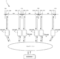
図1は、本発明の電力系統の保護システムの概略を示す構成図である。本発明の電力系統10には、変流器CT1〜6と遮断器CB1〜6が設けられる。電力系統の保護システム1は、事故区間に応じた遮断器CBへ遮断指令を送出するためにDMD端末2a〜2fと、DMD端末2a〜2f間を繋ぐネットワーク3、DMD端末2a〜2fにおいて、差動演算を行う際に使用する電気量を指示する演算処理部4を備える。
[1-1. Constitution]
FIG. 1 is a configuration diagram showing an outline of a power system protection system according to the present invention. In the
図示はしないが電力系統10には電気所が含まれる。この電気所に対して送電するための母線11A〜11Dや、電気所間を結ぶ送電線12A〜12Cにより電力系統10は構成される。本発明の電力系統の保護システム1は、その電力系統10内の送電線12A〜12Cに設けられた変流器CT1〜6と遮断器CB1〜6のデータを基にして、動作させる遮断器CB1〜6を決定し電力系統の保護を行う。
Although not shown, the
電力系統の保護システム1では、電力系統を構成する母線11A〜11Dや、送電線12A〜12Cの任意の場所に変流器CT及び遮断器CBを設置する。本実施形態では、母線11Aに対して送電線12Aの一端が接続している。この送電線12Aの母線11Aと接続する端部に変流器CT1と遮断器CB1とを配置する。
In the power
また、送電線12Aの一方の端部には、母線11Bと送電線12Bとが接続される。送電線12Aの母線11Bと送電線12Bと接続する端部には、変流器CT2と遮断器CB2とを配置する。
Further, the
送電線12Bの母線11Bと接続する端部には、変流器CT3と遮断器CB3とを配置する。送電線12Bの一方の端部には、母線11Cと送電線12Cが接続される。送電線12Bの母線11Cと接続する端部には、変流器CT4と遮断器CB4とを配置する。
A current transformer CT3 and a circuit breaker CB3 are arranged at the end of the
送電線12Cの母線11Cと接続する端部には、変流器CT5と遮断器CB5とを配置する。送電線12Cの一方の端部には、母線11Dが接続される。送電線12Cの母線11Dと接続する端部には、変流器CT6と遮断器CB6とを配置する。
A current transformer CT5 and a circuit breaker CB5 are disposed at the end of the
送電線12Aの端部に配置された変流器CT1と遮断器CB1はDMD端末2aと、送電線12Aの他端に配置された変流器CT2と遮断器CB2はDMD端末2bと、送電線12Bの端部に配置された変流器CT3と遮断器CB3はDMD端末2cと、送電線12Bの他端に配置された変流器CT4と遮断器CB4はDMD端末2dと、送電線12Cの端部に配置された変流器CT5と遮断器CB5はDMD端末2eと、送電線12Cの他端に配置された変流器CT6と遮断器CB6はDMD端末2fと、データの送受信可能に構成される。変流器CT1〜6からDMD端末2a〜2fに対しては、変流器CT1〜6で検出した電流データが送信される。遮断器CB1〜6からDMD端末2a〜2fに対しては、遮断器の動作情報が送信される。DMD端末2a〜2fから遮断器CB1〜6に対しては、遮断器の遮断指令が送信される。
Current transformer CT1 and circuit breaker CB1 disposed at the end of
DMD端末2aで受信した変流器CT1で検出した電気量は、ネットワーク3を介して、DMD端末2b〜2fに対して伝達される。同様にDMD端末2b〜2fで受信した変流器CT2〜6で検出した電気量は、ネットワーク3を介して各DMD端末2a〜2fに対して伝達される。
The quantity of electricity detected by the current transformer CT1 received by the
DMD端末2a〜2fで受信した変流器CT1〜6で検出した電気量は、ネットワーク3を介して、演算処理部4に対して伝達される。また、DMD端末2a〜2fで受信した遮断器CB1〜CB6の遮断器データもネットワーク3を介して、演算処理部4に対して伝達される。演算処理部4では、受信した電気量CT1〜6及び遮断器CB1〜CB6の遮断器データに基づいて、各DMD端末2a〜2fの保護演算を行うために使用する電気量を指示する使用電気量指示を出力する。
The quantity of electricity detected by the current transformers CT <b> 1 to 6 received by the
DMD端末2a〜2fは、事故区間に応じた遮断器へ遮断指令を出力する。図2に示すようにDMD端末2aは、電気量取得部21、遮断器データ取得部22、送信部23、受信部24、電気量テーブル25、電気量選択部26、保護演算部27、出力部28を備える。
The
電気量取得部21は、電力系統10に設置された変流器CT1で検出した電気量データIt1を取得する。電気量データIt1は、時間tにおける瞬時値データである。変流器CT1で検出した電気量データIt1はアナログデータであり、電気量取得部21はアナログデータの電気量データIt1をデジタルデータに変換する機能を備える。電気量取得部21で取得した電気量データIt1は、電気量テーブル25と、送信部23とに対して出力される。
Electric
遮断器データ取得部22は、電力系統に設置された遮断器CB1の遮断器情報である遮断器データを取得する。遮断器情報は、遮断器の投入/遮断情報を示す情報である。遮断器データ取得部22で取得した遮断器情報は、送信部23に対して出力される。
The circuit breaker data acquisition unit 22 acquires circuit breaker data that is circuit breaker information of the circuit breaker CB1 installed in the power system. The circuit breaker information is information indicating circuit breaker on / off information. The circuit breaker information acquired by the circuit breaker data acquisition unit 22 is output to the
送信部23は、ネットワーク3と接続し電気量データIt1及び遮断器情報b1を送信する。送信部23から送信される電気量データIt1は、DMD端末2b〜2fの受信部24に対して出力される。受信部24は、ネットワーク3と接続し、DMD端末2b〜2fから送信された電気量データIt2〜It6を受信する。受信部24で受信した電気量データIt2〜It6は、電気量テーブル25に対して出力される。
The
電気量テーブル25は、電気量取得部21で取得した電気量データIt1と、受信部24で受信した電気量データIt2〜It6を記憶する。図3は、電気量テーブル25に記憶される電気量テーブルの一例である。電気量は、各DMD端末2a〜2fの時間tにおける電気量として記憶される。例えば、時間t1におけるDMD端末2a〜2fの電気量は、It1〜It6として表される。
Electrical amount table 25 stores the electric quantity data I t1 acquired by the electric
電気量選択部26は、保護演算部27で差動演算を行う際に使用する電気量の選択を行う。すなわち、保護演算部27は、差動演算を行う演算部である。差動演算を行うためには、保護区間の端の電流値が必要である。電気量選択部26は、電気量テーブルに記憶された電気量データIt1〜It6の中から適切なデータを選択することにより、所定の保護区間における差動演算を可能にする。
The electrical
保護演算部27は、電気量データIt1〜It6の中から電気量選択部26で選択した電気量データに基づいて保護演算を行う演算部である。保護演算の結果、遮断器CB1で遮断が必要となった場合には、遮断指示を出力部に対して出力する。
The protection computation unit 27 is a computation unit that performs a protection computation based on the electrical quantity data selected by the electrical
出力部28は、受信した遮断指示を遮断器CB1に対して出力する。遮断指示を受信した遮断器CB1は、遮断状態となるように動作する。
The
演算処理部4は、DMD端末2a〜2fから送信された変流器CT1〜6で検出した電気量データIt1〜It6と、遮断器CB1〜6の遮断器データに基づいて、対象となるDMD端末2a〜2fで差動演算を行う際の電気量を選択する基準となる使用電気量を指示する。演算処理部4は、図4に示すように、受信部41、演算範囲選択部42、使用電気量決定部43、演算用データベース44、出力部45とを備える。
受信部41は、ネットワーク3と接続し、変流器CT1〜6で検出した電気量データIt1〜It6と、遮断器CB1〜6の遮断器データを受信する。
演算範囲選択部42は、演算用データベース44を参照し、受信した電気量データIt1〜It6と、遮断器CB1〜6の遮断器データに基づき演算範囲を主保護、N−1、N−2から選択する。主保護の場合の演算範囲は、最少の区間の演算を行う範囲であり、N−1の場合は、主保護区間より1区間広い範囲、N−2の場合は、主保護区間より2区間広い範囲である。
The calculation
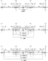
例えば、図5は、送電線12Bで事故が起こった場合の主保護区間、N−1の保護区間、N−2の保護区間を示す図である。図5に示すように、主保護区間は、送電線12Bに設置されたCB3とCB4の間の区間LP1となる。この場合、N−1の保護区間は、主保護区間より1区間広くなり、送電線12Aに設置されたCB2と、送電線12Cに設置されたCB5との間の区間となる。さらに、N−1の保護区間内の遮断器の動作状態を検出し、保護区間の範囲を限定することもできる。つまり、N−1の保護区間の範囲を、後述のCBF検出部46の検出結果に基づいて、主保護区間LP1の左右どちらかにだけ1区間広く設定する。換言すれば、限定したN−1の保護区間内に、事故区間が残るようN−1の区間を設定する。例えば、N−1の保護区間の範囲を主保護区間LP1の左に1区間広く設定した場合(図5のN−1(左))の保護区間は、送電線12Aに設置されたCB2と、送電線12Bに設置されたCB4の間の区間である。また、N−1の保護区間の範囲を主保護区間LP1の右に1区間広く設定し場合(図5のN−1(右))の保護区間は、送電線12Bに設置されたCB3と、送電線12Cに設置されたCB5との間の区間である。
For example, FIG. 5 is a diagram illustrating a main protection section, an N-1 protection section, and an N-2 protection section when an accident occurs in the
また、N−2の保護区間は、主保護区間より2区間広くなり、送電線12Aに設置されたCB1と、送電線12Cに設置されたCB6との間の区間となる。また、N−2の保護区間もN−1の保護区間と同様に、範囲を限定することもできる。つまり、N−2の保護区間の範囲として、N−1の保護区間の左右どちらかにだけ1区間広く設定する。この場合も、限定したN−2の保護区間内に、事故区間が残るようN−2の区間を設定する。例えば、N−2の保護区間をN−1保護区間の左に1区間広く設定した場合(図5のN−2(左))の保護区間は、送電線12Aに設置されたCB1と、送電線12Cに設置されたCB5との間の区間である。また、N−2の保護区間の範囲をN−1保護区間の右に1区間広く設定した場合(図5のN−2(右))の保護区間は、送電線12Aに設置されたCB2と、送電線12Cに設置されたCB6との間の区間である。同様に、主保護区間を送電線12Aや12Cの区間とした場合も、図示されない範囲も含めて左右にN−1の保護区間とN−2の保護区間が定義される。
Further, the N-2 protection section is two sections wider than the main protection section, and is a section between CB1 installed in the
また、演算範囲選択部42における演算範囲の選択には、電気力系統内の遮断器CBの遮断器不動作(CBF)を検出するCBF検出部46と、そのCBF検出部46での検出結果に基づいてN−1及びN−2の保護区間を決定する拡大方向決定部47を備える。
In addition, the calculation
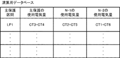
使用電気量決定部43は、演算用データベース44を参照し、演算範囲選択部42で選択した保護区間の際に各DMD端末2a〜2fの保護演算で使用する電気量を決定する。演算用データベース44は、図6に示すように、主保護区ごとの主保護の際に使用する使用電気量、N−1区間の使用電気量、N−2区間の使用電気量が記憶されている。使用電気量決定部43は、演算用データベース44に記憶されている使用電気量を基に、使用電気量指示を出力する。すなわち、主保護区間LP1の場合に、N−1区間で差動演算を行うためには、変流器CT2、CT5の電流データを使用するとの使用電気量指示を出力し、N−2区間で差動演算を行うためには、変流器CT1、CT6の電流データを使用するとの使用電気量指示を出力する。
The used electricity
出力部45は、使用電気量決定部43が決定した使用電気量をネットワーク3を介して各DMD端末2a〜2fに出力する。出力された使用電気量指示は各DMD端末2a〜2fの電気量選択部に入力する。
The
[1−2.システム動作]
以上のような構成を有する図1の電力系統の保護システム1の動作の概略は次の通りである。図7は、電力系統の保護システム1の保護における工程を示すフローチャートである。DMD端末2a〜2fは、電力系統10の各部の電流を変流器CT1〜6より取り込む。また、DMD端末2a〜2fは、自ら取り込んだ電流データを、ネットワーク3を介して他のDMD端末に対して送信する。DMD端末2a〜2fは、電力系統内で取り込んだ電流データを電気量テーブル25内に記憶しておく。また、DMD端末2a〜2fは、自ら取り込んだ電流データを、ネットワーク3を介して演算処理部4に伝送する。
[1-2. System operation]
The outline of the operation of the power
演算処理装置4は、DMD端末2a〜2fに対して、主保護用の電流データを使用し差動演算による保護演算を行うように指示する(S01)。各DMD端末2a〜2fでは、遮断器CBで区分された最小の事故区間と事故様相を判定するために、DMD端末2a〜2fから伝送された電力系統10内の電流データに基づき、差動演算による保護演算を行う(S02)。
The
保護演算では、事故が発生していない場合には、差動電流値Idは0近傍にあることから、CT固有誤差を考慮して差動電流値Idが設定値K以上である事を判定する(S03)。なお具体的な差動演算では右辺が固定的な設定値Kと電流の大きさに比例する設定値との和からなるが、公知であり、ここでは簡略化して設定値Kとのみ記している。 In the protection calculation, when no accident has occurred, the differential current value Id is in the vicinity of 0. Therefore, it is determined that the differential current value Id is equal to or greater than the set value K in consideration of the CT inherent error. (S03). In a specific differential calculation, the right side is a sum of a fixed set value K and a set value proportional to the magnitude of the current. However, this is well known, and here, only the set value K is shown in a simplified manner. .
差動電流値Idが設定値K未満である場合(S03のNO)には、引き続き保護演算を行う(S02)。差動電流値Idが設定値Kを超える場合(S03のYES)には、確認のため例えば5ms待機する(S04)。その後、遮断対象となる遮断器を選択する。遮断器の選択は、DMD端末2a〜2fでの差動演算の結果に基づき選択される(S05)。そして対象となる遮断器CBに対して遮断指示を出力可能なDMD端末2a〜2fから遮断指示が出力される(S06)。
When the differential current value Id is less than the set value K (NO in S03), the protection calculation is continued (S02). When the differential current value Id exceeds the set value K (YES in S03), for example, 5 ms is waited for confirmation (S04). Thereafter, the circuit breaker to be interrupted is selected. The selection of the circuit breaker is selected based on the result of differential operation at the
その後、各DMD端末2a〜2fは、演算処理装置4からの指示に基づき、N−1保護区間用の電流データを使用した差動演算による保護演算に切り替える(S11)。各DMD端末2a〜2fでは、演算処理装置4からの使用電気量指示に基づいて、電気量テーブルに記憶された電気量データを使用し、差動演算による保護演算を行う(S12)。
Then, each
保護演算の方法は、主保護用の電流データを使用する場合と同様であり、事故が発生していない場合には、差動電流値Idは0近傍にあることから、CT固有誤差を考慮して差動電流値Idが設定値K以上である事を判定する(S13)。差動電流値Idが設定値K未満である場合(S13のNO)には、主保護用の電流データを使用した遮断器の動作により、保護が行われているので、N−1保護区間用の電流データを使用した差動演算による保護演算を行わず終了する。差動電流値Idが設定値K以上である場合(S13のYESには、遮断器不動作(CBF)と判定し、不動作の遮断器CBの検出を行う(S15、S16)。 The protection calculation method is the same as that when the current data for main protection is used. When no accident has occurred, the differential current value Id is close to 0. It is then determined that the differential current value Id is greater than or equal to the set value K (S13). When the differential current value Id is less than the set value K (NO in S13), the protection is performed by the operation of the circuit breaker using the current data for main protection. End without performing protection operation by differential operation using the current data. When the differential current value Id is equal to or greater than the set value K (YES in S13, it is determined that the circuit breaker is not operating (CBF)), and the non-operating circuit breaker CB is detected (S15, S16).
動作をしなかった遮断器CBの場所に基づいて、N−1区間の決定を行う(S16)。その後、N−1で拡大処理を行うために遮断対象となる遮断器を選択する。遮断器の選択は、演算処理部4の拡大方向決定部により決定する(S17)。そして対象となる遮断器CBに対して遮断指示を出力可能なDMD端末2a〜2fから遮断指示が出力される(S18)。 Based on the location of the circuit breaker CB that did not operate, the N-1 section is determined (S16). Thereafter, a circuit breaker to be interrupted is selected in order to perform the enlargement process at N-1. The selection of the circuit breaker is determined by the enlargement direction determination unit of the arithmetic processing unit 4 (S17). And the interruption | blocking instruction | indication is output from DMD terminal 2a-2f which can output the interruption | blocking instruction | indication with respect to the circuit breaker CB used as object (S18).
その後、各DMD端末2a〜2fは、演算処理装置4からの指示に基づき、N−2保護区間用の電流データを使用した差動演算による保護演算に切り替える(S21)。以下の工程は、N−1保護区間用の電流データを使用した保護演算時と同様である(S22〜28)。
Then, each
[1−3.事故除去動作の具体例]
例えば、図8(a)では、主保護区間LP1として送電線12Bの両端にある変流器CT3とCT4から取り込まれた電流データIt3とIt4を用いた保護演算を行う。主保護区間LP1において、系統事故が発生した場合には、It3+It4より求められる差動電流値Idは、設定値K以上となる。この結果を受けて、遮断器CB3と遮断器CB4に対して遮断指示が行われる。その後、保護区間をN−1に拡大した差動演算が行われる。保護演算における差動電流値Idは、It2+It5より求められる。図8(a)では、遮断器CB3、CB4が正常に動作し、電流を遮断しているのでIt3とIt4は0である。また、事故電気流が遮断器CB3、CB4で遮断されているためN−1区間に流れる電流はIt2+It5は設定値K未満となり、保護演算を終了する。
[1-3. Specific example of accident removal operation]
For example, to protect calculation using current data I t3 and I t4 taken from in FIG. 8 (a), the a current transformer CT3 with a main protective section LP1 across the
一方、図8(b)では、遮断器CB2、CB3、CB5が正常、CB4が不動作である。このため、遮断器CB4では遮断が行われずN−1区間には故障による電流が流れることとなる。そのためIt2+It5は、設定値K以上となる。この結果と、遮断を拡大すべき方向が主保護区間LP1の左側(CB2側)と右側(CB5側)のいずれであるのかの拡大方向決定を受けて、遮断器CB5に対して遮断指示が行われる。図8(b)では、遮断を拡大すべき方向が右側(CB5側)という決定を受けた場合の、主保護区間LP1の右へ1区間広げた区間(N−1保護(右))が保護区間である。 On the other hand, in FIG. 8B, the circuit breakers CB2, CB3, and CB5 are normal and CB4 is not operating. For this reason, the circuit breaker CB4 is not interrupted, and a current due to a failure flows in the N-1 section. Therefore, I t2 + I t5 is equal to or greater than the set value K. In response to this result and an enlargement direction determination as to which of the left side (CB2 side) and the right side (CB5 side) of the main protection section LP1 is the direction in which the interruption should be enlarged, the interruption instruction is issued to the breaker CB5. Is called. In FIG. 8B, when the direction in which the interruption should be expanded is determined to be the right side (CB5 side), the section (N-1 protection (right)) expanded by one section to the right of the main protection section LP1 is protected. It is a section.
その後、保護区間をN−2に拡大した差動演算が行われる。保護演算における差動電流値Idは、It1+It6より求められる。図8(b)では、遮断器CB3、CB5が共に正常に動作しているので、遮断器CB3、CB5により遮断が行われためN−1区間を超えて事故による電流が流れることはない。そのため、N−2区間に流れる電流It1+It6は設定値K未満となり、保護演算を終了する。 Thereafter, a differential operation is performed by expanding the protection interval to N-2. The differential current value Id in the protection calculation is obtained from I t1 + I t6 . In FIG. 8B, since both of the circuit breakers CB3 and CB5 are operating normally, the circuit breakers CB3 and CB5 block the circuit, so that no current flows due to the accident beyond the N-1 section. Therefore, the current I t1 + I t6 flowing in the N-2 section becomes less than the set value K, and the protection calculation is finished.
一方、図8(c)では、遮断器CB1、CB2、CB3、CB6が正常、遮断器CB4、CB5が不動作であるため、遮断器CB5では遮断が行われずN−2区間には故障による電流が流れることとなる。そのためIt1+It6は、設定値K以上となる。この結果と、遮断を拡大すべき方向がN−1区間の左側(CB1側)と右側(CB6側)のいずれであるのかの拡大方向決定を受けて、遮断器CB6に対して遮断指示が行われる。図8(c)では、遮断を拡大すべき方向が右側(CB6側)という決定を受けた場合の、N−1の区間の右へ1区間広げた区間(N−2保護(右))が保護区間である。 On the other hand, in FIG. 8C, the circuit breakers CB1, CB2, CB3, and CB6 are normal, and the circuit breakers CB4 and CB5 are inoperative. Will flow. Therefore, I t1 + I t6 is equal to or greater than the set value K. In response to this result and an enlargement direction determination as to which of the left side (CB1 side) and the right side (CB6 side) of the N-1 section is the direction in which the interruption should be enlarged, the interruption instruction is issued to the breaker CB6. Is called. In FIG.8 (c), when the direction which should enlarge interruption | blocking is received that the right side (CB6 side) was received, the area (N-2 protection (right)) which expanded one section to the right of the section of N-1 is. It is a protection section.
図8(c)では、遮断器CB6は正常に動作しているので、遮断器CB3、CB6により遮断が行われた時点でN−2区間を超えて事故電流が流れないため、保護演算を終了する。 In FIG. 8 (c), since the circuit breaker CB6 is operating normally, the accidental current does not flow beyond the N-2 section when the circuit breakers CB3 and CB6 are interrupted. To do.
以上の様に、保護演算における差動電流値Idとして選択する電気量を変更することにより、同じ構成のままに、保護区間を主保護区間、主保護区間より1区間拡大したN−1区間、主保護区間より2区間拡大したN−2区間と拡大することができる。 As described above, by changing the amount of electricity selected as the differential current value Id in the protection calculation, the protection section is the main protection section, the N-1 section expanded by one section from the main protection section, with the same configuration, It can be expanded with an N-2 section that is two sections larger than the main protection section.
[拡大差動シークエンス]
図9(a)のタイムチャートに示すように、主保護区間の保護演算における差動電流値Idは設定値K以上という結果を受けた主保護区間の保護演算後、一定時間(例えば5ms)の待機の後に遮断器に対して遮断指示が出力される。その後、行われる保護区間をN−1に拡大した差動演算の結果、差動電流値Idは設定値K未満となり、保護演算を終了する。
[Expanded differential sequence]
As shown in the time chart of FIG. 9A, the differential current value Id in the protection operation in the main protection interval is a predetermined time (for example, 5 ms) after the protection operation in the main protection interval in which the result that the set value K is exceeded. After waiting, a break instruction is output to the breaker. Thereafter, as a result of the differential calculation in which the protection interval to be performed is expanded to N−1, the differential current value Id becomes less than the set value K, and the protection calculation ends.
図9(b)のタイムチャートに示すように、主保護区間の保護演算における差動電流値Idは設定値K以上という結果を受けた主保護区間の保護演算後、例えば5msの待機の後に遮断器に対して遮断指示が出力される。その後、行われる保護区間をN−1に拡大した差動演算の結果、差動電流値Idは設定値K以上となる。 As shown in the time chart of FIG. 9B, the differential current value Id in the protection operation of the main protection section is cut off after the protection calculation of the main protection section that has received the result that the set value K or more, for example, after waiting for 5 ms. A shutoff instruction is output to the device. Thereafter, the differential current value Id becomes equal to or greater than the set value K as a result of the differential operation in which the protection interval to be performed is expanded to N-1.
その結果を受けて一定時間(例えば150ms)の遮断器CBの遮断器不動作(CBF)を検出時間後、遮断器に対して遮断指示が出力される。その後、行われる保護区間をN−2に拡大した差動演算の結果、差動電流値Idは設定値K未満となり、保護演算を終了する。 In response to the result, a break instruction is output to the breaker after detecting a breaker non-operation (CBF) of the breaker CB for a certain time (for example, 150 ms). Thereafter, as a result of the differential calculation in which the protection interval to be performed is expanded to N−2, the differential current value Id becomes less than the set value K, and the protection calculation is terminated.
図9(c)のタイムチャートでは、保護区間をN−1に拡大した差動演算の結果、差動電流値Idは設定値K以上となる。その結果を受けて例えば150msの遮断器CBの遮断器不動作(CBF)を検出時間後、遮断器に対して遮断指示が出力される。その後、行われる保護区間をN−2に拡大した差動演算の結果、差動電流値Idは設定値K以上となる。その結果を受けて例えば150msの遮断器CBの遮断器不動作(CBF)を検出時間後、遮断器に対して遮断指示が出力される。
In the time chart of FIG. 9C, the differential current value Id is equal to or greater than the set value K as a result of the differential calculation with the protection interval expanded to N-1. In response to the result, for example, after detecting the circuit breaker non-operation (CBF) of the circuit breaker CB for 150 ms, a circuit break instruction is output to the circuit breaker. Thereafter, the differential current value Id becomes equal to or larger than the set value K as a result of the differential operation in which the protection interval to be performed is expanded to
[1−4.効果]
以上のように、本発明の電力系統の保護システムによれば、DMD端末における保護演算部において、差動演算を行うための電気量データを切替えることで、最短区間、最短区間より1区間広いN−1区間、最短区間より2区間広いN−2区間と拡大させることができる。
[1-4. effect]
As described above, according to the power system protection system of the present invention, the protection calculation unit in the DMD terminal switches the electric quantity data for performing the differential calculation, thereby reducing the shortest section and the one section wider than the shortest section. -1 section, N-2 section that is 2 sections wider than the shortest section can be expanded.
また、本発明では、DMD端末2a〜2fは、自らの電気量取得部で取得した電気量データと、電力系統10内の他のDMD端末の電気取得部で取得した電気量データを電気量テーブルに記憶する。この際、電気量データをネットワーク3を介して送受信することで、系統内の電気量データをほぼリアルタイムで電気量テーブルに記憶することができる。
Further, in the present invention, the
さらに、保護区間を拡大する場合に、系統における遮断器の動作情報に基づいて拡大方向を決定する。これにより、保護区間をN−1、N−2と拡大した場合にでも、保護区間の範囲を最低限に抑えることができる。そのため、保護動作により影響を受ける区間を狭くすることができる。また、この第1の実施形態では、拡大方向の決定を遮断器の動作情報に基づいて決定したが、他の情報に基づいて決定してもよい。 Furthermore, when expanding a protection area, an expansion direction is determined based on the operation information of the circuit breaker in a system | strain. Thereby, even when a protection area is expanded with N-1 and N-2, the range of a protection area can be suppressed to the minimum. Therefore, the section affected by the protection operation can be narrowed. Moreover, in this 1st Embodiment, although the determination of the expansion direction was determined based on the operation information of a circuit breaker, you may determine based on other information.
[2.他の実施形態]
本明細書においては、本発明に係る複数の実施形態を説明したが、これらの実施形態は例として提示したものであって、発明の範囲を限定することを意図していない。具体的には、発明の範囲を逸脱しない範囲で、種々の省略や置き換え、変更を行うことができる。これらの実施形態やその変形は、発明の範囲や要旨に含まれると同様に、特許請求の範囲に記載された発明とその均等の範囲に含まれるものである。
[2. Other Embodiments]
In the present specification, a plurality of embodiments according to the present invention have been described. However, these embodiments are presented as examples and are not intended to limit the scope of the invention. Specifically, various omissions, replacements, and changes can be made without departing from the scope of the invention. These embodiments and modifications thereof are included in the invention described in the claims and equivalents thereof as well as included in the scope and gist of the invention.
例えば、第1の実施形態では、演算範囲選択部42における演算範囲を主保護、N−1、N−2から選択したが、Nは3以上でもよい。N−3まで選択する場合には、図10の様に演算データベースにおいて、N−3を選択した場合の使用電気量の取得箇所を記憶しておく。
For example, in the first embodiment, the calculation range in the calculation
また、演算処理部4の演算用データベースには、主保護区間における使用電気量取得箇所、N−1区間における使用電気量取得箇所、N−2区間における使用電気量取得箇所を記憶しておくが、それぞれの使用電気量の記憶のタイミングは、電力系統10に新たな変電所を追加するなどの系統構成の変化があったタイミングで内容を更新することもできる。これにより、実情に合う電力系統10に対して保護を行うことができる。
The calculation database of the
さらに、使用電気量取得箇所の記憶のタイミングは、系統において事故が発生したタイミングでも良い。系統において事故が発生したタイミングで更新を行うことにより、その事故の内容に合わせた使用電気量のみを記憶すればよいので、データの容量が少なくなると共に、更新の手間も減少する。 Furthermore, the timing of storing the used electricity amount acquisition location may be the timing at which an accident occurs in the system. By updating at the timing when an accident occurs in the system, it is only necessary to store the amount of electricity used according to the content of the accident, so the data capacity is reduced and the updating effort is reduced.
また例えば、第1の実施形態では、使用電気量や拡大方向の決定を演算処理部4で実行したが、これらの一方もしくは両方を、DMD端末2a〜2fで実行させてもよい。この場合、使用電気量の決定には、演算用データベース44をDMD端末2a〜2fに持たせずに、あらかじめ手動でDMD端末に設定しておく方法をとることもできる。
Further, for example, in the first embodiment, the amount of electricity used and the enlargement direction are determined by the
1 … 保護システム
10 … 電力系統
11A〜11D… 母線
12A〜12C… 送電線
2a〜2f … DMD端末
21 … 電気量取得部
22 … 遮断器データ取得部
23 … 送信部
24 … 受信部
25 … 電気量テーブル
26 … 電気量選択部
27 … 保護演算部
28 … 出力部
3 … ネットワーク
4 … 演算処理部
41 … 受信部
42 … 演算範囲選択部
43 … 使用電気量決定部
44 … 演算用データベース
45 … 出力部
46 … 遮断器不動作検出部
47 … 拡大方向決定部
DESCRIPTION OF
Claims (9)
前記保護システムは、事故区間に応じた遮断器へ遮断指令を出力する複数の端末装置と、
前記端末装置間で情報を伝達するためのネットワークと、
前記ネットワークに接続し、前記端末装置に保護演算に使用する電気量データを指定する使用電気量の取得箇所を指示する演算装置を備え、
前記端末装置は、前記電力系統内の電気量データを取得する電気量取得部と、
取得した前記電力系統内の電気量データを記憶する電気量記憶部と、
前記電気量記憶部に記憶された電気量データと前記演算装置からの使用電気量に基づいて保護演算を行う保護演算部を備えることを特徴とする電力系統の保護システム。 In the power system protection system that determines the accident section of the power system using the amount of electricity in the power system and operates the circuit breaker according to the accident section,
The protection system includes a plurality of terminal devices that output a cutoff command to a circuit breaker according to an accident section;
A network for transmitting information between the terminal devices ;
An arithmetic device that connects to the network and instructs the terminal device to acquire the amount of electricity used for specifying the amount of electricity data to be used for protection computation,
The terminal device includes an electric quantity acquisition unit that acquires electric quantity data in the power system;
An electrical quantity storage unit for storing electrical quantity data in the acquired electric power system;
A protection system for a power system, comprising: a protection calculation unit that performs a protection calculation based on the amount of electricity stored in the amount of electricity storage unit and the amount of electricity used from the arithmetic unit.
前記使用電気量の取得箇所の更新を行うことを特徴とする請求項1乃至3の何れか1項に記載の電力系統の保護システム。 The arithmetic unit, when there is a change in the system configuration in the power system,
The power system protection system according to any one of claims 1 to 3, wherein an acquisition location of the amount of used electricity is updated.
前記使用電気量の取得箇所の更新を行うことを特徴とする請求項1乃至3の何れか1項に記載の電力系統の保護システム。 The arithmetic unit, when an accident occurs in the power system,
The power system protection system according to any one of claims 1 to 3, wherein an acquisition location of the amount of used electricity is updated.
前記保護システムは、事故区間に応じた遮断器へ遮断指令を出力する複数の端末装置と、
前記端末装置間で情報を伝達するためのネットワークと、
を備え、
前記端末装置は、前記電力系統内の電気量データを取得する電気量取得部と、
取得した前記電力系統内の電気量データを記憶する電気量記憶部と、
前記電気量記憶部に記憶された複数の保護区間の電気量データの中から保護演算に使用する保護区間の電気量データを設定する使用電気量設定部と、
前記使用電気量設定部が設定した電気量データに基づいて保護演算を行う保護演算部を備えることを特徴とする電力系統の保護システム。 In the power system protection system that determines the accident section of the power system using the amount of electricity in the power system and operates the circuit breaker according to the accident section,
The protection system includes a plurality of terminal devices that output a cutoff command to a circuit breaker according to an accident section;
A network for transmitting information between the terminal devices ;
With
The terminal device includes an electric quantity acquisition unit that acquires electric quantity data in the power system;
An electrical quantity storage unit for storing electrical quantity data in the acquired electric power system;
A used electricity amount setting unit for setting the electricity amount data of the protection section used for the protection calculation from the electricity amount data of the plurality of protection sections stored in the electricity amount storage unit;
A power system protection system comprising a protection calculation unit that performs a protection calculation based on the amount of electricity data set by the used electricity amount setting unit.
前記端末装置間で情報を伝達するためのネットワークと、
前記ネットワークに接続し、前記端末装置に保護演算に使用する電気量データを指定する使用電気量の指示をする演算装置を備える電力系統の保護方法において、
前記端末装置により、前記電力系統内の電気量データを取得する電気量取得処理と、
取得した前記電力系統内の電気量データを記憶する電気量記憶部と、
前記記憶された電気量データと前記演算装置からの使用電気量に基づいて保護演算を行う保護演算処理と、
を含むことを特徴とする電力系統の保護方法。 A plurality of terminal devices that output a cut-off command to a circuit breaker according to an accident section of the power system;
A network for transmitting information between the terminal devices ;
In a protection method for an electric power system comprising an arithmetic device that is connected to the network and instructs the terminal device to specify electric energy data to be used for protection calculation,
Electric amount acquisition processing for acquiring electric amount data in the power system by the terminal device;
An electrical quantity storage unit for storing electrical quantity data in the acquired electric power system;
A protection calculation process for performing a protection calculation based on the stored amount of electricity data and the amount of electricity used from the arithmetic unit;
A method for protecting an electric power system, comprising:
前記端末装置間で情報を伝達するためのネットワークを備える電力系統の保護方法において、
前記端末装置により、前記電力系統内の電気量データを取得する電気量取得処理と、
取得した前記電力系統内の電気量データを記憶する電気量記憶部と、
前記電気量記憶部に記憶された複数の保護区間の電気量データから保護演算に使用する保護区間の電気量データを設定する使用電気量設定処理と、
前記使用電気量設定処理の設定に基づいて保護演算を行う保護演算処理と、
を含むことを特徴とする電力系統の保護方法。 A plurality of terminal devices that output a cut-off command to a circuit breaker according to an accident section of the power system;
In a power system protection method comprising a network for transmitting information between the terminal devices ,
Electric amount acquisition processing for acquiring electric amount data in the power system by the terminal device;
An electrical quantity storage unit for storing electrical quantity data in the acquired electric power system;
A use electricity amount setting process for setting the electricity amount data of the protection section used for the protection calculation from the electricity amount data of the plurality of protection sections stored in the electricity amount storage unit;
A protection operation process for protecting operation based on the setting of the prior Symbol used electric quantity setting processing,
A method for protecting an electric power system, comprising:
Priority Applications (1)
| Application Number | Priority Date | Filing Date | Title |
|---|---|---|---|
| JP2014013698A JP6315552B2 (en) | 2014-01-28 | 2014-01-28 | Power system protection system and power system protection method |
Applications Claiming Priority (1)
| Application Number | Priority Date | Filing Date | Title |
|---|---|---|---|
| JP2014013698A JP6315552B2 (en) | 2014-01-28 | 2014-01-28 | Power system protection system and power system protection method |
Publications (2)
| Publication Number | Publication Date |
|---|---|
| JP2015142433A JP2015142433A (en) | 2015-08-03 |
| JP6315552B2 true JP6315552B2 (en) | 2018-04-25 |
Family
ID=53772460
Family Applications (1)
| Application Number | Title | Priority Date | Filing Date |
|---|---|---|---|
| JP2014013698A Active JP6315552B2 (en) | 2014-01-28 | 2014-01-28 | Power system protection system and power system protection method |
Country Status (1)
| Country | Link |
|---|---|
| JP (1) | JP6315552B2 (en) |
Families Citing this family (1)
| Publication number | Priority date | Publication date | Assignee | Title |
|---|---|---|---|---|
| JP6963835B2 (en) * | 2019-09-25 | 2021-11-10 | 株式会社コルグ | Playback control device, playback control method, and program |
Family Cites Families (6)
| Publication number | Priority date | Publication date | Assignee | Title |
|---|---|---|---|---|
| JPH05207645A (en) * | 1992-01-22 | 1993-08-13 | Toshiba Corp | Fault detection method for current differential protection relay |
| JPH08340632A (en) * | 1995-06-12 | 1996-12-24 | Hitachi Ltd | Current differential protection relay device and abnormality detecting method thereof |
| JPH10248158A (en) * | 1997-03-05 | 1998-09-14 | Mitsubishi Electric Corp | Wide-area system protection relay and automatic recovery device in case of breaker failure |
| JP2001045645A (en) * | 1999-07-30 | 2001-02-16 | Central Res Inst Of Electric Power Ind | Power system wide area protection system and method, and program recording medium |
| JP2004088919A (en) * | 2002-08-27 | 2004-03-18 | Kansai Electric Power Co Inc:The | Current differential protection relay |
| JP4050694B2 (en) * | 2003-12-26 | 2008-02-20 | 中国電力株式会社 | Total protection system with self-end judgment function for power system and total protection method with self-end judgment function |
-
2014
- 2014-01-28 JP JP2014013698A patent/JP6315552B2/en active Active
Also Published As
| Publication number | Publication date |
|---|---|
| JP2015142433A (en) | 2015-08-03 |
Similar Documents
| Publication | Publication Date | Title |
|---|---|---|
| CN101297450B (en) | Fault protection system and method for an electrical power distribution system | |
| JP2018064416A (en) | Two parallel line transmission line protection system | |
| US10074972B2 (en) | System and method of controlling current-limiters in ring systems | |
| JP5068200B2 (en) | Current differential protection relay | |
| JP2017017832A (en) | Server device | |
| JP6315552B2 (en) | Power system protection system and power system protection method | |
| CN106329492B (en) | A kind of simple bus bar protecting method based on system topological | |
| JP2013090445A (en) | Power system protection system | |
| JP2013062974A (en) | Protection relay system | |
| JP2007244138A (en) | Protective circuit | |
| JP2012130107A (en) | Ground fault protection relay system and ground fault protection method | |
| CN104466923A (en) | Power distribution network protection circuit and system connected into microgrid | |
| JP2008259327A (en) | Reclosing system | |
| JP6129679B2 (en) | Power system stabilization system and power system stabilization method | |
| JP2018026926A (en) | Power system protective system | |
| JP3556044B2 (en) | Current differential relay | |
| JP2014217103A (en) | Current differential protective relay device and power line protective system | |
| GB2521143A (en) | An improved ring main unit | |
| JP2015154670A (en) | Short circuit protection relay system | |
| CN104155578B (en) | The fault detection method of the T-shaped 10kV distribution lines based on on-pole switch | |
| KR102127471B1 (en) | Total AI Backup Protection System for Substation | |
| JP2019068571A (en) | Channel selection protection relay device and parallel two-line power transmission line protection system | |
| CN104155579B (en) | 10KV distribution line and fault detection method of the M types based on on-pole switch | |
| JP4602271B2 (en) | Protection system for two parallel transmission lines | |
| JP6645759B2 (en) | Current differential relay system |
Legal Events
| Date | Code | Title | Description |
|---|---|---|---|
| A621 | Written request for application examination |
Free format text: JAPANESE INTERMEDIATE CODE: A621 Effective date: 20170127 |
|
| A977 | Report on retrieval |
Free format text: JAPANESE INTERMEDIATE CODE: A971007 Effective date: 20171127 |
|
| A131 | Notification of reasons for refusal |
Free format text: JAPANESE INTERMEDIATE CODE: A131 Effective date: 20171205 |
|
| A521 | Written amendment |
Free format text: JAPANESE INTERMEDIATE CODE: A523 Effective date: 20180202 |
|
| TRDD | Decision of grant or rejection written | ||
| A711 | Notification of change in applicant |
Free format text: JAPANESE INTERMEDIATE CODE: A712 Effective date: 20180216 |
|
| A01 | Written decision to grant a patent or to grant a registration (utility model) |
Free format text: JAPANESE INTERMEDIATE CODE: A01 Effective date: 20180220 |
|
| A61 | First payment of annual fees (during grant procedure) |
Free format text: JAPANESE INTERMEDIATE CODE: A61 Effective date: 20180322 |
|
| R150 | Certificate of patent or registration of utility model |
Ref document number: 6315552 Country of ref document: JP Free format text: JAPANESE INTERMEDIATE CODE: R150 |