JP6309552B2 - Vehicle seat - Google Patents
Vehicle seat Download PDFInfo
- Publication number
- JP6309552B2 JP6309552B2 JP2016001814A JP2016001814A JP6309552B2 JP 6309552 B2 JP6309552 B2 JP 6309552B2 JP 2016001814 A JP2016001814 A JP 2016001814A JP 2016001814 A JP2016001814 A JP 2016001814A JP 6309552 B2 JP6309552 B2 JP 6309552B2
- Authority
- JP
- Japan
- Prior art keywords
- seat
- bracket
- airbag device
- attached
- main body
- Prior art date
- Legal status (The legal status is an assumption and is not a legal conclusion. Google has not performed a legal analysis and makes no representation as to the accuracy of the status listed.)
- Active
Links
Images


Classifications
-
- B—PERFORMING OPERATIONS; TRANSPORTING
- B60—VEHICLES IN GENERAL
- B60R—VEHICLES, VEHICLE FITTINGS, OR VEHICLE PARTS, NOT OTHERWISE PROVIDED FOR
- B60R21/00—Arrangements or fittings on vehicles for protecting or preventing injuries to occupants or pedestrians in case of accidents or other traffic risks
- B60R21/02—Occupant safety arrangements or fittings, e.g. crash pads
- B60R21/16—Inflatable occupant restraints or confinements designed to inflate upon impact or impending impact, e.g. air bags
- B60R21/20—Arrangements for storing inflatable members in their non-use or deflated condition; Arrangement or mounting of air bag modules or components
- B60R21/207—Arrangements for storing inflatable members in their non-use or deflated condition; Arrangement or mounting of air bag modules or components in vehicle seats
-
- B—PERFORMING OPERATIONS; TRANSPORTING
- B60—VEHICLES IN GENERAL
- B60N—SEATS SPECIALLY ADAPTED FOR VEHICLES; VEHICLE PASSENGER ACCOMMODATION NOT OTHERWISE PROVIDED FOR
- B60N2/00—Seats specially adapted for vehicles; Arrangement or mounting of seats in vehicles
- B60N2/58—Seat coverings
-
- B—PERFORMING OPERATIONS; TRANSPORTING
- B60—VEHICLES IN GENERAL
- B60N—SEATS SPECIALLY ADAPTED FOR VEHICLES; VEHICLE PASSENGER ACCOMMODATION NOT OTHERWISE PROVIDED FOR
- B60N2/00—Seats specially adapted for vehicles; Arrangement or mounting of seats in vehicles
- B60N2/64—Back-rests or cushions
- B60N2/646—Back-rests or cushions shape of the cushion
-
- B—PERFORMING OPERATIONS; TRANSPORTING
- B60—VEHICLES IN GENERAL
- B60R—VEHICLES, VEHICLE FITTINGS, OR VEHICLE PARTS, NOT OTHERWISE PROVIDED FOR
- B60R21/00—Arrangements or fittings on vehicles for protecting or preventing injuries to occupants or pedestrians in case of accidents or other traffic risks
- B60R21/02—Occupant safety arrangements or fittings, e.g. crash pads
- B60R21/16—Inflatable occupant restraints or confinements designed to inflate upon impact or impending impact, e.g. air bags
- B60R21/23—Inflatable members
- B60R21/231—Inflatable members characterised by their shape, construction or spatial configuration
- B60R21/23138—Inflatable members characterised by their shape, construction or spatial configuration specially adapted for side protection
- B60R2021/23146—Inflatable members characterised by their shape, construction or spatial configuration specially adapted for side protection seat mounted
Landscapes
- Engineering & Computer Science (AREA)
- Mechanical Engineering (AREA)
- Aviation & Aerospace Engineering (AREA)
- Transportation (AREA)
- Seats For Vehicles (AREA)
- Air Bags (AREA)
Description
本発明は、シートフレームに取付けられてシートパッドを裏面側から支持する平板状の支持部材と、支持部材に取付けられたエアバッグとを備えた乗物用シートに関する。 The present invention relates to a vehicle seat that includes a flat plate-like support member that is attached to a seat frame and supports a seat pad from the back side, and an airbag that is attached to the support member.
この種の乗物用シートとして、シートバックが、シート骨格をなすシートフレームと、乗員を弾性的に支持するシートパッドと、シートバックボードと、サイドエアバッグ装置を備えた乗物用シートが公知である(特許文献1を参照)。このシートバックでは、本発明の支持部材に相当するシートバックボードがシートフレームの着座側に取付けられている。このシートバックボードは、シートパッドを裏面側から支持する樹脂製の部材であり、平板状のボード本体と、複数のバックバネ部を有している。複数のバックバネ部は、それぞれシート幅方向に延びる帯状の部位であり、ボード本体の着座側に配設されてシートパッドを裏面から弾性的に支持する。そしてボード本体には、シートフレームに係止め可能な下部連結固定部と、サイドエアバッグ装置を取付けるための取付部が設けられている。下部連結固定部は、平断面視で略逆U字状に形成された部位であり、シート幅方向におけるボード本体の周縁に設けられている。また取付部は、下部連結固定部の末端からシート幅方向外側に突出する平板部位であり、この取付部には、サイドエアバッグ装置をボルト止め可能なボルト挿設孔が設けられている。またサイドエアバッグ装置は、スタッドボルトが裏面側から突出した立方体状の部材であり、ガスの流入により膨張可能なエアバッグと、エアバッグにガスを供給するインフレータが内蔵されている。 As this type of vehicle seat, a vehicle seat including a seat frame in which a seat back forms a seat skeleton, a seat pad that elastically supports an occupant, a seat back board, and a side airbag device is known. (See Patent Document 1). In this seat back, a seat back board corresponding to the support member of the present invention is attached to the seating side of the seat frame. The seat back board is a resin member that supports the seat pad from the back side, and includes a flat board main body and a plurality of back spring portions. Each of the plurality of back spring portions is a belt-like portion extending in the seat width direction, and is disposed on the seating side of the board body to elastically support the seat pad from the back surface. The board body is provided with a lower connecting and fixing portion that can be locked to the seat frame, and an attachment portion for attaching the side airbag device. The lower connecting and fixing portion is a portion formed in a substantially inverted U shape in a plan view, and is provided at the periphery of the board body in the seat width direction. The attachment portion is a flat plate portion that protrudes outward in the seat width direction from the end of the lower connecting and fixing portion, and the attachment portion is provided with a bolt insertion hole that can bolt the side airbag device. The side airbag device is a cubic member in which a stud bolt projects from the back surface side, and includes an airbag that can be inflated by inflow of gas and an inflator that supplies gas to the airbag.
そしてシートバックボードのボード本体をシートフレームに取付けるとともに、サイドエアバッグ装置を、シートバックボードの取付部に着座側から締結して固定する。このときサイドエアバッグ装置のスタッドボルトを、取付部のボルト挿設孔に挿通しつつ取付部の裏側でナットに螺合する。そしてシートパッドを、バックバネ部に支持させながらシートフレームの着座側に配設してシートカバーで被覆する。この状態においては、サイドエアバッグ装置が、ボード本体の取付部に取付けられてシートパッドの裏面側に配置されている。そして乗物衝突時においては、インフレータが作動してエアバッグを膨張させ、この膨張したエアバッグが、シートパッドから飛出しながらシートカバーを破断させてシート外に展開する。このエアバッグの展開時においては、着座側に向けて膨張するエアバッグを、サイドエアバッグ装置とともに裏面側の取付部によって支持する。このため公知技術では、樹脂製の取付部を、エアバッグ展開時の応力に対応すべくボード本体に比して肉厚としたり、取付部の裏側に平板状のリブを突設したりしている。 And while attaching the board main body of a seat back board to a seat frame, the side airbag apparatus is fastened and fixed to the attaching part of a seat back board from the seating side. At this time, the stud bolt of the side airbag device is screwed into the nut on the back side of the mounting portion while being inserted through the bolt insertion hole of the mounting portion. Then, the seat pad is disposed on the seat frame side while being supported by the back spring portion, and is covered with the seat cover. In this state, the side airbag device is attached to the attachment portion of the board body and disposed on the back side of the seat pad. In the event of a vehicle collision, the inflator is activated to inflate the airbag, and the inflated airbag breaks out of the seat cover while popping out of the seat pad and deploys outside the seat. When the airbag is deployed, the airbag that is inflated toward the seating side is supported by the attachment portion on the back surface side together with the side airbag device. For this reason, in the known technology, the resin mounting portion is made thicker than the board body in order to cope with the stress at the time of airbag deployment, or a flat rib is projected on the back side of the mounting portion. Yes.
ところで公知技術では、エアバッグ展開時の応力に対応するため、樹脂製の取付部を肉厚としたりリブを設けたりして構造的に補強する必要がある。このため公知技術の構成では、取付部が過度に大きくなることがあり、シートの内部スペースの関係から、すんなり採用できる構成ではなかった。また公知技術のようにサイドエアバッグ装置を樹脂製の取付部に締結する構成では、取付部の座屈変形等によってナットが緩むことがあり、サイドエアバッグ装置の取付け安定性にやや欠ける構成となりがちであった。本発明は上述の点に鑑みて創案されたものであり、本発明が解決しようとする課題は、比較的コンパクトな構成によって、エアバッグ装置などの他部材を支持部材に安定的に取付けることにある。 By the way, in the known technique, in order to cope with the stress when the airbag is deployed, it is necessary to reinforce structurally by making the resin mounting portion thick or providing ribs. For this reason, in the structure of a well-known technique, an attaching part may become large too much and it was not the structure which can be employ | adopted easily from the relationship of the internal space of a sheet | seat. In addition, in the configuration in which the side airbag device is fastened to the resin mounting portion as in the known art, the nut may be loosened due to buckling deformation of the mounting portion, etc., so that the mounting stability of the side airbag device is somewhat lacking. It was apt. The present invention has been devised in view of the above points, and the problem to be solved by the present invention is to stably attach other members such as an airbag device to a support member with a relatively compact configuration. is there.
上記課題を解決するための手段として、第1発明の乗物用シートは、シート骨格をなすシートフレームと、乗員を弾性的に支持可能なシートパッドと、シートパッドの着座側を被覆するシートカバーと、シートフレームに取付けられてシートパッドを裏面側から支持する平板状の支持部材と、支持部材に取付けられたエアバッグ装置を備える。本発明では、エアバッグ装置のエアバッグが、シートパッドの飛出部を通ってシートカバーの破断部からシート外に展開可能である。この種の構成では、比較的コンパクトな構成によって、支持部材とは異なる他部材であるエアバッグ装置を支持部材に安定的に取付けられることが望ましい。 As means for solving the above problems, a vehicle seat of the first invention includes a seat frame that forms a seat skeleton, a seat pad that can elastically support an occupant, and a seat cover that covers a seating side of the seat pad. A flat plate-like support member attached to the seat frame and supporting the seat pad from the back surface side, and an airbag device attached to the support member. In the present invention, the airbag of the airbag device can be deployed out of the seat from the breakage portion of the seat cover through the protruding portion of the seat pad. In this type of configuration, it is desirable that the airbag device, which is another member different from the support member, can be stably attached to the support member by a relatively compact configuration.
そこで本発明では、支持部材が、シートパッドに対面状に配置された樹脂製の本体部と、本体部に比して変形しにくい素材で形成されたブラケット部とを一体的に備える。そしてエアバッグ装置が、ブラケット部に取付けられて飛出部の裏側に配置されている。本発明では、ブラケット部が、本体部に比して変形しにくい素材(曲がりにくい又は破損しにくい素材)で形成されている。このため他部材であるエアバッグ装置を取付けるためのブラケット部を、構造的に補強する必要がなく低質量でコンパクトな構成とすることができる。そしてエアバッグ装置のエアバッグの展開時には、相対的に変形しにくいブラケット部にてエアバッグ装置を安定的に支持することができる。
また第1発明の乗物用シートは、シートカバーの裏側でエアバッグ装置の少なくとも一部を囲うように設けられた帯状の力布を備えている。そして力布のシート着座側の端部が破断部に取付けられているとともに、力布のシート裏側の端部がブラケット部に取付けられている。本発明では、他部材である力布の端部を、相対的に変形しにくいブラケット部に安定的に取付けることができる。
また第1発明の乗物用シートは、ブラケット部が、力布の通過を許容する通過部を有し、通過部の内面の少なくとも一部が、本体部の一部で構成された被覆部にて覆われており、力布が通過部に挿通された状態で配索されている。本発明では、シート着座側から裏側に力布を配索する場合、この力布を、本体部から露出するブラケット部の通過部を通過させながら適切に配索することができる。そして通過部の内面が被覆部にて覆われていることから、力布を、極力破損させることなく通過部に挿通させておくことができる。
Therefore, in the present invention, the support member integrally includes a resin main body disposed on the seat pad in a face-to-face manner and a bracket portion formed of a material that is less likely to deform than the main body. And the airbag apparatus is attached to the bracket part, and is arrange | positioned on the back side of the protrusion part. In the present invention, the bracket portion is formed of a material that is not easily deformed compared to the main body portion (a material that is difficult to bend or break). For this reason, it is not necessary to reinforce structurally the bracket part for attaching the airbag apparatus which is another member, and it can be set as a low mass and a compact structure. And at the time of expansion | deployment of the airbag of an airbag apparatus, an airbag apparatus can be stably supported by the bracket part which cannot be deform | transformed relatively.
The vehicle seat according to the first aspect of the invention further includes a belt-like force cloth provided so as to surround at least a part of the airbag device on the back side of the seat cover. The end of the power cloth on the seat seating side is attached to the break portion, and the end of the power cloth on the seat back side is attached to the bracket portion. In the present invention, the end portion of the bedding that is the other member can be stably attached to the bracket portion that is relatively difficult to deform.
In the vehicle seat according to the first aspect of the invention, the bracket portion has a passage portion that allows the passing of the force cloth, and at least a part of the inner surface of the passage portion is a covering portion that is constituted by a part of the main body portion. It is covered, and it is routed in a state where the blanket is inserted through the passage. In the present invention, when a webbing is routed from the seat seating side to the back side, the webbing can be properly routed while passing through the passing part of the bracket part exposed from the main body part. And since the inner surface of the passage part is covered with the covering part, the webbing can be inserted through the passage part without being damaged as much as possible.
第2発明の乗物用シートは、第1発明の乗物用シートにおいて、ブラケット部が、エアバッグ装置を固定可能な孔状の固定部を有し、エアバッグ装置を固定するための固定具が、本体部から露出した固定部に挿通された状態で固定されている。本発明では、エアバッグ装置を固定するための固定具を、本体部から露出し且つ相対的に変形しにくいブラケット部の固定部に挿通しつつ安定的に固定することができる。 The vehicle seat of the second invention is the vehicle seat of the first invention, wherein the bracket portion has a hole-like fixing portion capable of fixing the airbag device, and a fixing tool for fixing the airbag device is It is fixed in a state of being inserted through a fixing portion exposed from the main body portion. In the present invention, the fixing tool for fixing the airbag device can be stably fixed while being inserted through the fixing portion of the bracket portion that is exposed from the main body portion and is relatively difficult to deform.
第3発明の乗物用シートは、第2発明の乗物用シートにおいて、ボルト状の固定具が、固定部に挿通され且つ固定部の裏側で留め具に螺合されている。本発明では、エアバッグ装置を締結するためのボルト状の固定具を、本体部から露出するブラケット部の固定部に挿通しつつ留め具に螺合する。このとき座面となる固定部の周縁が座屈変形しにくくされて軸力を出して締結できるため、固定具に対して留め具をしっかり螺合させておくことができる。 A vehicle seat according to a third aspect is the vehicle seat according to the second aspect, wherein a bolt-shaped fixing tool is inserted into the fixing portion and is screwed to the fastener on the back side of the fixing portion. In the present invention, a bolt-shaped fixture for fastening the airbag device is screwed into the fastener while being inserted through the fixing portion of the bracket portion exposed from the main body portion. At this time, since the peripheral edge of the fixing portion serving as the seating surface is hardly buckled and deformed and can be fastened with an axial force, the fastener can be firmly screwed to the fixing tool.
第4発明の乗物用シートは、第1発明〜第3発明のいずれかの乗物用シートにおいて、力布のシート裏側の端部に平板状の取付け具が設けられているとともに、取付け具が、取付け具を厚み方向に貫通する挿通孔を有し、挿通孔に、ブラケット部から突出する棒状の固定ピンを挿通可能である。そして取付け具が、ブラケット部から突出する棒状の固定ピンに挿通された状態で固定されているとともに、ブラケット部に、固定ピンを中心とした取付け具の回転を規制する規制部が設けられている。本発明では、規制部によって、力布の取付け具を、ブラケット部の適所に正しく配置しつつ固定ピンに固定することができる。 The vehicle seat of the fourth invention is the vehicle seat of any one of the first invention to the third invention, wherein a flat fixture is provided at the end of the back of the power cloth, and the fixture is It has an insertion hole that penetrates the fixture in the thickness direction, and a rod-shaped fixing pin that protrudes from the bracket portion can be inserted into the insertion hole. The fixture is fixed in a state where the fixture is inserted through a rod-like fixing pin protruding from the bracket portion, and a restriction portion is provided on the bracket portion to restrict rotation of the fixture around the fixing pin. . In the present invention, the baffle fixture can be fixed to the fixing pin by the restricting portion while being correctly arranged at an appropriate position of the bracket portion.
第5発明の乗物用シートは、第1発明〜第4発明のいずれかの乗物用シートにおいて、シートカバーのシート着座側とは反対のシート裏側の端部がブラケット部に取付けられている。本発明では、他部材であるシートカバーの端部を、相対的に変形しにくいブラケット部に安定的に取付けることができる。 The vehicle seat according to a fifth aspect of the present invention is the vehicle seat according to any one of the first to fourth aspects, wherein the end of the seat back side opposite to the seat seating side of the seat cover is attached to the bracket portion. In this invention, the edge part of the seat cover which is another member can be stably attached to the bracket part which is hard to deform | transform relatively.
第6発明の乗物用シートは、第1発明〜第5発明のいずれかの乗物用シートにおいて、ブラケット部の少なくとも一部が本体部に埋設状に一体化されているとともに、埋設状とされたブラケット部に、本体部の一部が入り込んで配置されている孔状又は切欠き状のアンカー部が設けられている。本発明では、ブラケット部の少なくとも一部が本体部に埋設状に一体化されており、さらにブラケット部が、その埋設部分に設けられたアンカー部によって本体部に安定的に保持されている。 The vehicle seat according to a sixth aspect of the present invention is the vehicle seat according to any one of the first to fifth aspects of the invention, wherein at least a part of the bracket portion is embedded in the main body portion and is embedded. The bracket portion is provided with a hole-shaped or notched-shaped anchor portion in which a part of the main body portion is inserted. In the present invention, at least a part of the bracket portion is integrally embedded in the main body portion, and the bracket portion is stably held on the main body portion by the anchor portion provided in the embedded portion.
第7発明の乗物用シートは、第1発明〜第6発明のいずれかの乗物用シートにおいて、エアバッグ装置がブラケット部に取付けられた状態を基準として、ブラケット部に、エアバッグ装置よりもシート幅方向外方で着座側に向けて突出する突出部が設けられている。本発明では、エアバッグ装置の外方に配置する突出部により、エアバッグを正しい方向に向けてスムーズに展開させることができる。 The vehicle seat according to a seventh aspect of the present invention is the vehicle seat according to any one of the first to sixth aspects of the present invention, wherein the seat is more seated in the bracket portion than the air bag device based on the state in which the airbag device is attached to the bracket portion. A projecting portion that projects outward in the width direction toward the seating side is provided. In the present invention, the airbag can be smoothly deployed in the correct direction by the protruding portion disposed outside the airbag device.
第8発明の乗物用シートは、第1発明〜第7発明のいずれかの乗物用シートにおいて、ブラケット部が、本体部よりも変形しにくい金属製の部材で構成されている。本発明では、樹脂製の本体部に比して変形しにくい金属製のブラケット部にエアバッグ装置を安定的に取付けることができる。 A vehicle seat according to an eighth aspect of the present invention is the vehicle seat according to any one of the first to seventh aspects, wherein the bracket portion is made of a metal member that is more difficult to deform than the main body portion. In the present invention, the airbag device can be stably attached to a metal bracket portion that is less likely to be deformed than a resin main body portion.
本発明に係る第1発明によれば、比較的コンパクトな構成によって、他部材であるエアバッグ装置を支持部材に安定的に取付けることができる。また第1発明によれば、比較的コンパクトな構成によって、他部材である力布を支持部材に安定的に取付けることができる。また第1発明によれば、力布を支持部材に取付ける安定的且つ性能良く取付けることができる。また第2発明によれば、エアバッグ装置を支持部材により安定的に取付けることができる。また第3発明によれば、エアバッグ装置を支持部材により安定的に締結して取付けることができる。また第4発明によれば、力布を支持部材にさらに安定的に取付けることができる。また第5発明によれば、比較的コンパクトな構成によって、他部材であるシートカバーを支持部材に安定的に取付けることができる。また第6発明によれば、他部材を支持部材に更に安定的に取付けることができる。また第7発明によれば、エアバッグ装置を支持部材に安定的且つ性能よくに取付けることができる。そして第8発明によれば、他部材を支持部材により更に安定的に取付けることができる。
According to the first aspect of the present invention, the airbag device as another member can be stably attached to the support member with a relatively compact configuration. According to the first aspect of the present invention, it is possible to stably attach the webbing as another member to the support member with a relatively compact configuration. Further, according to the first aspect of the present invention, it is possible to attach the webbing to the support member stably and with good performance. According to the second invention, the airbag device can be stably attached by the support member. According to the third aspect of the invention, the airbag device can be stably fastened and attached by the support member. According to the fourth aspect of the present invention, it is possible to more stably attach the webbing to the support member. According to the fifth aspect of the present invention, the seat cover as another member can be stably attached to the support member with a relatively compact configuration. According to the sixth invention, the other member can be more stably attached to the support member. According to the seventh invention, the airbag device can be attached to the support member stably and with good performance. According to the eighth aspect of the invention, the other member can be more stably attached by the support member.
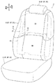
以下、本発明を実施するための形態を、図1〜図15を参照して説明する。各図には、便宜上、乗物用シートの前後方向と左右方向と上下方向を示す矢線を図示することがある。図1の乗物用シート2は、シートクッション4と、シートバック6と、ヘッドレスト8を有する。これらシート構成部材は、各々、シート骨格をなすシートフレーム(4F,6F,8F)と、シート外形をなすシートパッド(4P,6P,8P)と、シートパッドを被覆するシートカバー(4S,6S,8S)を有する。そしてシートクッション4の後部にシートバック6(詳細後述)の下部が起倒可能に連結するとともに、起立状態のシートバック6の上部にヘッドレスト8が配設される。
Hereinafter, embodiments for carrying out the present invention will be described with reference to FIGS. In each drawing, for convenience, arrow lines indicating the front-rear direction, the left-right direction, and the up-down direction of the vehicle seat may be illustrated. The vehicle seat 2 in FIG. 1 includes a
[シートバック]
シートバック6は、図2を参照して、上述の基本構成(6F,6P,6S)と、エアバッグ装置20と、一対の力布31,32と、本発明の支持部材に相当するバックパン40を有する(各部材の詳細は後述)。ここでシートパッド6Pは、後述するバックパン40を介してシートフレーム6Fの着座側に取付けられており、シートパッド6Pの着座側がシートカバー6Sで被覆されている。なおシートバック6の裏面側には平板状のバックボード9が取付けられており、このバックボード9は、シート幅方向における周縁が着座側に向けて湾曲している(図2では、便宜上、バッグボードの周縁部分のみ図示する)。そしてシートバック6は、図1を参照して、乗員の肩甲骨や肩部等を支える上部領域6Aが、乗員の腰部等を支える下部領域6Bに対して、前側に折れ曲がる形に傾動(中折れ)することができる。
[Seatback]
Referring to FIG. 2, the seat back 6 is a back pan corresponding to the above-described basic configuration (6F, 6P, 6S), the
またエアバッグ装置20(詳細後述)は、図2及び図10を参照して、後述するバックパン40のブラケット部50に取付けられてシート内に配設されている。そして乗物衝突時においては、エアバッグ装置20に内蔵されたエアバッグ24がシート外に展開して乗員を保護する。このとき膨張するエアバッグ24が、図2を参照して、シートパッド6Pの飛出部6PXを通りながら、一対の力布31,32を介してシートカバー6Sの破断部6SXを開口させつつシート外に展開することとなる。このエアバッグ展開時においては、シート外に向けて膨張するエアバッグ24を、エアバッグ装置20とともに裏面側のバックパン40のブラケット部50によって支持する。この種の構成では、シートの内部スペースなどを考慮して、比較的コンパクトな構成によって、バックパン40にエアバッグ装置20を安定的に取付けられることが望ましい。そこで後述するコンパクトな構成によって、バックパン40にエアバッグ装置20を安定的に取付けることとした。以下、各構成について詳述する。
Moreover, the airbag apparatus 20 (detailed later) is attached to a
[基本構成]
シートフレーム6Fは、図3を参照して、正面視で略矩形状の枠部材であり、剛性に優れる金属や硬質樹脂等の素材にて形成できる。このシートフレーム6Fは、上部骨格をなすアッパフレーム部12と、側部骨格をなす左右のサイドフレーム部14と、下部骨格をなすロアフレーム部16を一つなぎで有する。そしてアッパフレーム部12には、一対のヘッドレストブラケット13と、一対のブラダ15が設けられている。一対のヘッドレストブラケット13は、ヘッドレスト8の下部から突出するヘッドレストステー(図示省略)を挿設可能な筒状の部材であり、シート幅方向におけるアッパフレーム部12の中央に適宜の間隔で固定されている。また一対のブラダ15は、後述するバックパン40のアッパパン42を傾倒させる正面視で略矩形の平板部材であり、アッパフレーム部12の左右にそれぞれ設けられている。これら各ブラダ15は、その背後の進退機構(図示省略)とともに平板状の取付けブラケット15aを介してアッパフレーム部12等に固定されている。また各サイドフレーム部14とロアフレーム部16には、正面視で略矩形の一対の締結板18Fが取付けられている。これら締結板18Fには、図示しないボルト部材を挿通可能な貫通孔(符号省略)が設けられており、後述するバックパン40のロアパン44を締結して固定可能である。ここで一方の締結板18Fは、右側のサイドフレーム部14の下部外側に取付けられている。また他方の締結板18Fは、一方の締結板18Fよりも下方に配置されており、左側のサイドフレーム部14下端からロアフレーム部16左端にかけての角部分に取付けられている。
[Basic configuration]
Referring to FIG. 3, the
またシートパッド6Pは、図2及び図3を参照して、シート外形をなして乗員を弾性的に支持可能な部材であり、エアバッグ24の飛出し箇所となる飛出部6PXを有する。ここでシートパッド6Pの材質は特に限定しないが、例えばポリウレタンフォーム(密度:10kg/m3〜60kg/m3)等の発泡樹脂で形成できる。このシートパッド6Pは、正面視で略矩形状をなしており、天板メイン部6aと、天板サイド部6bと、区画溝部6cと、飛出部6PXと、通路部W1,W2を有する。天板メイン部6aは、シートパッド6P中央の平坦な部位であり、乗員の着座(背もたれ)が可能である。また天板サイド部6bは、天板メイン部6aの側方で着座側に突出する部位であり、例えばコーナリング走行時に乗員の側部56を支持できる。また区画溝部6cは、シートバック6の上部領域6Aと下部領域6Bの間に配置する溝部であり、天板メイン部6aと天板サイド部6bを横断して配置されている。この区画溝部6cから上の天板メイン部6aと天板サイド部6bが上部領域6Aを構成しており、後述するバックパン40のアッパパン42の前傾に追従して傾倒することができる。そして図2を参照して、右側の天板サイド部6bの頂部付近には、他の部位に比して薄肉化された飛出部6PXが形成されており、シートカバー6Sの破断部6SX(後述)に対面状に配置されている。また右側の天板メイン部6aと天板サイド部6bの間と、右側の天板サイド部6bの右側部後方には、それぞれシートパッド6P内外を連通する通路部W1,W2が設けられている。これら通路部W1,W2には、対応する各力布31,32(後述)がそれぞれ配索されることとなる。
2 and 3, the
またシートカバー6Sは、図2を参照して、シートパッド6Pを被覆可能な袋状の部材であり、エアバッグ24のシート外への展開基点となる破断部6SXを有する。このシートカバー6Sは、複数の表皮ピース(SP1〜SP3等)を縫合して形成されており、符号SEW1とSEW2は隣り合う表皮ピースの縫合部を示す。例えば第一表皮ピースSP1は、天板メイン部6aの上部を被覆する表皮ピースである。また第二表皮ピースSP2は、右側の天板サイド部6bの上部着座側を被覆する表皮ピースである。そして第三表皮ピースSP3は、右側の天板サイド部6bの上部側面から後側を被覆する表皮ピースである。なお各表皮ピースの素材として、天然繊維又は合成繊維からなる布帛(織物,編物,不職布)や皮革(天然皮革,合成皮革)を例示できる。そして破断部6SXは、他のシートカバー6S部分よりも脆弱な部位であり、エアバッグ24の膨張時に破断して開口することができる。この破断部6SXは、第二表皮ピースSP2と第三表皮ピースSP3の縫合部SEW2であり、右側の天板サイド部6bの頂点付近においてシート上下方向に延設されている。また図12を参照して、第三表皮ピースSP3の端部は内折りされて輪状となるように縫付けられており、この端部内にはワイヤ18が挿入されている。このワイヤ18の一部は、第三表皮ピースSP3の端部に設けた切欠きから露出しており、この露出したワイヤ18部分が、後述するブラケット部50の掛止部71〜73に掛止されて取付けられることとなる。
Further, referring to FIG. 2, the
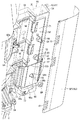
[エアバッグ装置]
ここでエアバッグ装置20は、図2及び図10を参照して、シート上下方向に長尺な略立方体状の部材であり、シートバック6右側の内部に配設されている。このエアバッグ装置20は、図10を参照して、一対の固定具21,22と、未膨張状態のエアバッグ24と、このエアバッグ24にガスを供給するガス供給装置26とを備える。一対の固定具21,22は、エアバッグ装置20の裏面に固定されたスタッドボルト状の部材であり、その周面にネジ溝が設けられて後述の留め具80が螺合可能である。またエアバッグ24は、ガスの流入により膨張する袋体であり、ガス供給装置26には、ガス発生剤又は高圧ガスが封入されている。そしてエアバッグ装置20を、後述するようにバックパン40のブラケット部50に締結固定してシート内に配設する。そして乗物衝突時においては、衝突の衝撃を受けてガス供給装置26が作動し、エアバッグ装置20内のエアバッグ24が、ガスの供給により膨張しながら、飛出部6PXと破断部6SXを通ってシート外に展開することとなる。
[Airbag device]
2 and 10, the
[力布・取付け具]
一対の力布(第一力布31,第二力布32)は、図2を参照して、それぞれシートカバー6Sの裏側でエアバッグ装置20の周りに配置される帯状の部材である。ここで各力布31,32の素材は特に限定しないが、エアバッグ24の膨張時の圧力では破損しない程度の剛性を備えることが好ましく、典型的にはシートカバー6Sよりも伸び難い布帛製である。そして各力布31,32のシート着座側の一端側は、後述するようにシートカバー6Sの破断部6SXに取付けられる。また各力布31,32のシート裏側の他端側には取付け具34a,34bが取付けられており、これら取付け具34a,34bが、後述するブラケット部50に固定されることとなる。各取付け具34a,34bは、図11を参照して、断面視で略L字状をなす略矩形の平板部材であり、その一片が、ブラケット部50の裏面に対面配置可能であるとともに、他片が、一片から湾曲又は屈曲して着座側に突出している。また各取付け具34a,34bには、後述するブラケット部50に締結するための挿通孔34Hと、各力布31,32を取付けるための取付け孔35Hとが設けられている。ここで取付け孔35Hは、各取付け具34a,34bの他片側に設けられた貫通孔であり、この取付け孔35Hに、各力布31,32の端部を輪状とした部分が挿通されている。また挿通孔34Hは、ブラケット部50の固定ピン68を挿通可能な貫通孔であり、各取付け具34a,34bの一片の略中央に設けられている。
[Blanket / Fitting]
The pair of webbings (the
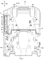
[バックパン(支持部材)]
バックパン40は、本発明の支持部材に相当する平板部材であり、図3を参照して、シートフレーム6Fの着座側に取付けられてシートパッド6Pを裏側から支持することができる。このバックパン40は、図4〜図6を参照して、正面視で略矩形をなす樹脂製の本体部41(アッパパン42,ロアパン44)と、後述する金属製のブラケット部50を有する。アッパパン42は、シートバック起立時を基準として本体部41の上部側をなす平板部位であり、一対の支承凹部42aが設けられている。一対の支承凹部42aは、アッパパン42の上部左右に設けられた略矩形の凹み部位であり、シートフレーム6Fへの取付け状態時においては、シート後方に突出配置され且つ対応するブラダ15に当接可能な位置に配置される。またロアパン44は、シートバック起立時を基準として本体部41の下部側をなす平板部位であり、一対のボルト受け部44aが設けられている。これらボルト受け部44aは、シート幅方向におけるロアパン44の左右位置にそれぞれ設けられており、その裏面側に、図示しないボルト部材を螺合可能な固定凹部44H(非貫通孔)が形成されている。そして右方のボルト受け部44aは、シートフレーム6Fへの取付け状態時においてサイドフレーム部14下部に設けた一方の締結板18Fに対面状に配置され、左方のボルト受け部44aは、サイドフレーム部14下端に設けた他方の締結板18Fに対面状に配置されることとなる。
[Back pan (supporting member)]
The
そして本体部41をなすアッパパン42とロアパン44は、起立状態のシートバック6において上下方向に並んで配置されている。これらアッパパン42とロアパン44は、後述するシートフレーム6Fへの取付け状態時を基準として、シート幅方向における周縁部分が次第に着座側に湾曲している。またアッパパン42とロアパン44は、図4及び図6を参照して、これらの間に配設された一対のヒンジピン46で連結されている。各ヒンジピン46は、シート幅方向に延びる棒状部材であり、本体部41を裏面から見てその左右に設けられている。そしてアッパパン42の下縁が、ロアパン44の上縁に対してヒンジピン46の軸周りに回転可能に連結されている。こうすることでアッパパン42が、後述するようにシートフレーム6Fに固定されたロアパン44に対してシート前方に傾倒可能とされる。
The
[ブラケット部]
ブラケット部50は、図5、図7及び図8を参照して、ハット断面形状を有する平板部材で構成されており、本体部41に比して変形しにくい素材で形成されて相対的に曲がりにくく又は破損しにくくされている。ここでブラケット部50の材質は特に限定しないが、鋼系(ステンレス鋼等)、アルミニウム合金系、マグネシウム合金系、チタン合金系等の金属を例示できる。このブラケット部50は、本体部41よりも薄肉化されてその質量が低減されており、正面視で長方形状の底面部52と、底面部52の右側に設けた立壁状の突出部54と、底面部52の左側に設けたクランク状の側部56とを有する。突出部54は、ブラケット部50の右側を屈曲させることで形成されており、図2のようにエアバッグ装置20を取付けた状態においては、エアバッグ装置20よりもシート幅方向外側(図では右側)に配置して着座側に突出する。この突出部54の前端は、本体部41をなす樹脂にて覆われており、この突出部54を覆う樹脂部分がシート前方に向けて延長している(本発明の突出部は、突出部54自体のほか、この突出部54から前方に突出する樹脂部分を含むことができる)。また側部56は、ブラケット部50の左側をクランク状に屈曲させながら突出させることで形成されており、その末端側の側部端部56aが底面部52に比して着座側に一段高くされている。これら突出部54と側部56には、図5及び図7を参照して、複数の円形状の貫通孔(後述のアンカー部60となるべき部分)が適宜の間隔で設けられている。そしてブラケット部50には、後述するように他部材としてのエアバッグ装置20とシートカバー6Sと各力布31,32を取付けることができる。このためブラケット部50には、一対の固定部62と、通過部64と、規制部66と、固定ピン68と、複数の掛止部71〜73が設けられている(各部の詳細は後述)。
[Bracket part]
Referring to FIGS. 5, 7, and 8, the
[アンカー部]
ここで図4〜図6を参照して、バックパン40においては、ブラケット部50と本体部41が一体的に設けられている。ブラケット部50と本体部41の一体化の手法は特に限定しないが、例えば一体成形によってブラケット部50を本体部41に埋設状に一体化することができる。すなわち本体部41のアッパパン42を成形する成形型(図示省略)のキャビティ内の適所にブラケット部50を予め配置しておき、この状態でアッパパン42を成形することにより、ブラケット部50を、アッパパン42の上部右側に埋設状に一体化することができる。このとき図9、図10及び図13を参照して、ブラケット部50の底面部52は本体部41から露出しているが、ブラケット部50の少なくとも一部である突出部54と側部56(通過部64を除く部分)は、本体部41に対して埋設されて一体化されている。このように金属製の突出部54と側部56を本体部41に埋設しておくことで、これら各部の端部(エッジ)によってシート内の部材が破損することを好適に回避できる。さらに突出部54と側部56には、ブラケット部50を厚み方向に貫通する孔状のアンカー部60が複数設けられており、各アンカー部60には、本体部41の一部が入り込んで配置されている。このようにブラケット部50の埋設部分にアンカー部60を設けることで、ブラケット部50を本体部41に安定的に保持させておくことができる。
[Anchor part]
4 to 6, in the
[固定部]
一対の固定部62は、図5を参照して、それぞれ底面部52の上部を厚み方向に貫通する略円形の孔部であり、エアバッグ装置20を取付けることができる。これら固定部62は、上下方向に適宜の間隔で配置されており、図9及び図10を参照して、各エアバッグ装置20の対応する固定具21,22をそれぞれ挿通することができる。これら一対の固定部62は、底面部52とともに本体部41から露出しており、シートフレーム6Fにバックパン40を取付けた状態においては、対応する固定具21,22を前後方向から挿通可能な位置に配置されている。
[Fixed part]
With reference to FIG. 5, the pair of fixing
[通過部]
通過部64は、図5及び図7を参照して、側部56の側部端部56aを厚み方向に貫通する孔部であり、第一力布31を挿通可能な開口寸法を有している。この通過部64の開口部分は、図2、図5及び図11を参照して、本体部41から露出しており、シートフレーム6Fにバックパン40を取付けた状態においては、エアバッグ装置20の少なくとも一部を囲う第一力布31の配索途中に配置されている。そして通過部64の内面は、図14を参照して、本体部41の一部をなす被覆部41aにて被覆されている。すなわち側部56が埋設されている本体部41が、被覆部41aとして通過部64の内面をも覆っている。このように通過部64の内面が被覆部41aにて覆われていることから、後述するように第一力布31を、極力破損させることなく通過部64に挿通させておくことができる。
[Passing section]
5 and 7, the
[規制部・固定ピン]
規制部66は、図7〜図9を参照して、底面部52の裏面下部に設けられた略矩形の凹み部位であり、各力布31,32のシート裏側の端部を取付けることができる。この規制部66は、本体部41から露出しており、平坦な底壁66aと、この底壁66aの上下端からそれぞれ立ち上がる立壁66b,66cとを有している。底壁66aは、底面部52の裏面上部に比して一段低くされており、図11及び図12を参照して、各力布31,32の取付け具34a,34bの一片を重ねて配置することができる。この底壁66aには、各取付け具34a,34bの挿通孔34Hに挿通可能なボルト状の固定ピン68が突出している。そして後述するように各取付け具34a,34bを重ねながら規制部66内に配置しつつ、各取付け具34a,34bの挿通孔34Hに固定ピン68を挿通する。このとき規制部66の立壁66b,66cによって、各取付け具34a,34bが固定ピン68を中心として回転することを規制することができる。
[Regulator / fixing pin]
With reference to FIGS. 7 to 9, the restricting
[掛止部]
複数の掛止部(第一掛止部71〜第三掛止部73)は、図7〜図9を参照して、底面部52の裏面側に設けられた爪状の部位であり、シートカバー6Sのシート裏側の端部を取付けることができる。第一掛止部71と第二掛止部72は、それぞれ底面部52の裏面左側から突出する爪状の部位であり、ブラケット部50の対応する部分をクランク状に切り起こすことで形成されている。また第三掛止部73は、底面部52の下端から突出する略L字状の突出片で形成されており、この突出片の端部は底面部52に対してクランク状に屈曲しながら突出して配置されている。これら複数の掛止部71〜73は、図12を参照して、底面部52とともに本体部41から露出しており、シートフレーム6Fにバックパン40を取付けた状態においては、上下方向に適宜の間隔で配置されている。そして後述するように、シートカバー6Sの取付け時においては、第三表皮ピースSP3の端部から露出するワイヤ18が、それぞれ対応する掛止部71〜73に掛止されることとなる。
[Hanging part]
The plurality of latching portions (the
[シートバックの組立作業]
図3を参照して、シートフレーム6Fの着座側にバックパン40を組付けつつ、このバックパン40の上部右側にエアバッグ装置20を配設する。このときロアパン44の一対のボルト受け部44aを、それぞれシートフレーム6Fの対応する締結板18Fにあてがいながら、図示しないボルト部材を介して締結して固定する。この状態では、アッパパン42がロアパン44に対して起立した状態で配置されるとともに、各支承凹部42aが、シートフレーム6Fのブラダ15に押し当てられている。そこでアッパパン42の上部と、アッパフレーム部12の上部を、ストッパとなる帯体(図示省略)で連結しておく。そしてブラダ15がシート前方に移動することにより、アッパパン42が、一対のヒンジピン46を基点としてロアパン44に対してシート前方に傾倒する。そしてアッパフレーム部12とアッパパン42の間で帯体が緊張して張った状態となることで、アッパフレーム部12に対するアッパパン42の前傾が停止することとなる。
[Assembly work of seat back]
Referring to FIG. 3, the
また上述の作業に前後して、エアバッグ装置20を、アッパパン42のブラケット部50に締結して固定する。このとき図9〜図11を参照して、エアバッグ装置20の各固定具21,22を、それぞれブラケット部50の対応する固定部62に挿通しながら裏側でナット状の留め具80に螺合する。このようにエアバッグ装置20をブラケット部50に締結して固定することで安定的に取付けることができる。このとき座面となる固定部62の周縁が座屈変形しにくくされて軸力を出して締結できるため、各固定具21,22に対して留め具80を極力緩ませることなくしっかり螺合させて締結しておくことができる。そしてこの取付け状態においては、エアバッグ装置20の裏側がブラケット部50の底面部52で支持された状態とされる。またエアバッグ装置20の右方に配置する突出部54により、後述するようにエアバッグ24を正しい方向である着座側に向けてスムーズに展開させることができる。
Further, before and after the above-described operation, the
つぎにシートパッド6Pを、図2を参照して、バックパン40を介してシートフレーム6Fの着座側に取付けたのち、各力布31,32とシートカバー6Sを順次取付ける。このときシートパッド6Pは、シートカバー6Sの張力などによりバックパン40に押し付けられた状態とされている。またシートパッド6Pの裏面を、バックパン40の着座側に接着又は貼着しておくことができる。こうすることでアッパパン42の前傾に伴ってシートパッド6Pの上部側を前傾させることが可能となり、シートバック6を中折れさせる構成とすることができる。そして図2を参照して、シートパッドの飛出部6PXが、右側の天板サイド部6bの頂部付近に配置されている。この状態においては、エアバッグ装置20が、ブラケット部50に取付けられて飛出部6PXの裏側に配置されている。
Next, referring to FIG. 2, the
そして第一力布31と第二力布32の一端側を、それぞれシートカバー6Sの着座側に配置しつつ、破断部6SXとしての縫合部SEW2に共縫いして取付けておく。つぎに第二力布32を、エアバッグ装置20を右側から囲うように、天板サイド部6bの右外面に沿って配置しつつ通路部W2からシート内に引込みながらブラケット部50の裏面側に配索する。また第一力布31を、エアバッグ装置20を左側から囲うように、天板サイド部6bの左外面に沿って配置しつつ通路部W1からシート内に引込みながらブラケット部50の裏面側に配索する。このとき第一力布31は、エアバッグ装置20の一部である左面側を囲いつつ、ブラケット部50の通過部64を通りながら着座側から裏側に配索される。この通過部64の内面は、図14を参照して、被覆部41aにて被覆されていることから、第一力布31を、極力破損させることなくスムーズに通過部64に挿通させておくことができる。そして図11及び図12を参照して、各力布31,32の他端に取付けられた取付け具34a,34bをブラケット部50の規制部66内に配置する。そして規制部66内で重ねられた各取付け具34a,34bの各挿通孔34Hに固定ピン68を挿通する。このとき規制部66の立壁66b,66cによって、各取付け具34a,34bが固定ピン68の軸周りに回転することを規制することができる。そして正しい姿勢で重ねられた取付け具34a,34bから突出した固定ピン68にナット部材NMを螺合することで、各力布31,32の端部をブラケット部50に安定的に取付けることができる。こうして一対の力布31,32が、シートカバー6Sの裏側でエアバッグ装置20を囲うように配置されることとなる。
Then, one end sides of the
つぎに図2を参照して、シートパッド6Pの着座側をシートカバー6Sで被覆する。このとき破断部6SXとしての縫合部SEW2を天板サイド部6bの頂点付近に配置しておく。また第三表皮ピースSP3によって天板サイド部6bの側面側を覆いつつ、第三表皮ピースSP3のシート裏側の端部を、バックボード9の内側からシート内に引込む。そして図12及び図15を参照して、第三表皮ピースSP3のシート裏側の端部をブラケット部50の裏側に引っ張り込みながら、第三表皮ピースSP3の端部から露出するワイヤ18を、それぞれ対応する掛止部71〜73に掛止する。こうすることでシートカバー6Sの端部をブラケット部50に安定的に取付けることができる。
Next, referring to FIG. 2, the seating side of the
[エアバッグの挙動]
図2を参照して、乗物衝突時においては、図10に示すエアバック装置20のエアバッグ24をシート外に展開させて乗員側部を保護する。このときエアバッグ24が、ガスの供給により膨張しつつ飛出部6PXを突き破りながらシートカバー6S側に向けて飛出すこととなる。つづいて一対の力布31,32が緊張して破断部6SXを開裂(開口)させることにより、エアバッグ24をシート外に展開させる。このエアバッグ展開時においては、シート外に向けて膨張するエアバッグ24を、エアバッグ装置20とともに裏面側の相対的に変形しにくいブラケット部50によって好適に支持することができる。またブラケット部50の突出部54によって、エアバッグ24を着座側に向けて正しく膨張させることができる。さらにシートカバー6Sとしての第三表皮ピースSP3の端部がブラケット部50に安定的に取付けられている。このためエアバッグ展開時においても、第三表皮ピースSP3の端部をブラケット部50に強固に留めておくことができ、シートカバー6Sが極力外れない構成である。さらに各力布31,32のシート裏側の端部が、それぞれブラケット部50に安定的に取付けられている。このため各力布31,32の緊張状態が好適に維持されて、破断部6SXを素早く開裂させて開口状態とすることができる。
[Airbag behavior]
Referring to FIG. 2, at the time of vehicle collision, the
以上説明したとおり本実施例では、ブラケット部50が、本体部41に比して変形しにくい素材(曲がりにくい又は破損しにくい素材)で形成されている。このため他部材であるエアバッグ装置20を取付けるためのブラケット部50を、構造的に補強する必要がなく低質量でコンパクトな構成とすることができる。例えば図2を参照して、ブラケット部50を相対的に薄肉化して質量を低減することにより、シンプルな構造とすることができる。そしてエアバッグ装置20のエアバッグ24の展開時には、相対的に変形しにくいブラケット部50にて他部材であるエアバッグ装置20を安定的に支持することができる。またエアバッグ装置20を締結するための固定具21,22を、本体部41から露出するブラケット部50の固定部62に挿通しつつ留め具80に螺合して締結する。このとき座面となる固定部62の周縁が座屈変形しにくくされて軸力を出して締結できるため、各固定具21,22に対して留め具80をしっかり螺合させておくことができる。またエアバッグ装置20の外方に配置する突出部54により、エアバッグ24を正しい方向に向けてスムーズに展開させることができる。また樹脂製の本体部41に比して変形しにくい金属製のブラケット部50にエアバッグ装置20を安定的に取付けることができる。またブラケット部50の少なくとも一部が本体部41に埋設状に一体化されており、さらにブラケット部50が、その埋設部分に設けられたアンカー部60によって本体部41に安定的に保持されている。こうして本実施例によれば、比較的コンパクトな構成にて、他部材であるエアバッグ装置20を支持部材としてのバックパン40に安定的に取付けることができる。
As described above, in the present embodiment, the
さらに本実施例では、他部材である各力布31,32の端部を、相対的に変形しにくいブラケット部50に安定的に取付けることができる。このとき第一力布31を、シート着座側から裏側に配索する場合、この第一力布31を、本体部41から露出するブラケット部50の通過部64を通過させながら適切に配索することができる。そして通過部64の内面が被覆部41aにて覆われていることから、第一力布31を、極力破損させることなく通過部64に挿通させておくことができる。また規制部66によって、力布31,32の取付け具34a,34bを、ブラケット部50の適所に正しく配置しつつ固定ピン68に締結して固定することができる。また他部材であるシートカバー6Sの端部を、相対的に変形しにくいブラケット部50に安定的に取付けることができる。こうして本実施例によれば、比較的コンパクトな構成にて、他部材である各力布31,32とシートカバー6Sを支持部材としてのバックパン40に安定的に取付けることができる。
Furthermore, in the present embodiment, the end portions of the
本実施形態の乗物用シートは、上述した実施形態に限定されるものではなく、その他各種の実施形態を取り得る。本実施形態では、ブラケット部50の構成(形状,寸法,配置位置,配設数,素材など)を説明したが、同部の構成を限定する趣旨ではない。例えばブラケット部に対してエアバッグ装置を締結以外の手法で取付けることができ、カシメ付けや、溶接や接着などの手法で直接的に取付けることができ、他の取付け部材を介して間接的に取付けることもできる。なおカシメ付けの手法は特に限定しないが、スピンカシメ、ハトメカシメ、リベットカシメ、パーリングカシメ、ダボカシメを例示できる。またブラケット部は、本体部よりも変形しにくい素材で形成されておればよく、例えば極度に硬く変形しにくい繊維強化プラスチックなどの樹脂にて形成することもできる。またブラケット部から突出部と側部の少なくとも一方を省略することもできる。
The vehicle seat of the present embodiment is not limited to the above-described embodiment, and can take other various embodiments. In the present embodiment, the configuration (shape, dimension, arrangement position, number of arrangement, material, etc.) of the
また本実施形態では、ブラケット部50に、アンカー部60と、一対の固定部62と、通過部64と、規制部66と、固定ピン68と、複数の掛止部71〜73を設ける例を説明した。このブラケット部の各種部位の構成(形状,寸法,配置位置,配設数など)は適宜変更可能である。例えば固定部の形成位置や形成数は、エアバッグ装置の構成に応じて適宜変更可能である。また通過部は、力布を通過可能な切欠き状の部位であってもよい。また一対の通過部をブラケット部に設けるとともに、各通過部に、対応する力布をそれぞれ通過させておくこともできる。また通過部の内面は、その一部が被覆部に被覆されていてもよく、被覆部に被覆されていない状態であってもよい。またアンカー部も、孔状(貫通孔又は非貫通の凹部)や切欠き状であってもよく、ブラケット部の構成に応じてアンカー部を適宜省略することもできる。また規制部の構成も、取付け具の回転を規制できる限り適宜変更可能であり、例えばブラケット部から突出しつつ取付け具の周囲に配置する凸部で構成されていてもよい。また潰れ変形可能な棒状または円筒状の固定ピンに、取付け具をカシメ付けにて固定する構成とすることができる。またブラケット部には、他部材である力布とシートカバーの少なくとも一方を取付けることができ、両部材を取付けない構成とすることもできる。また他部材の例として、シート内に配置される各種の部材(ワイヤや配線やモータなど)を例示できる。そして取付けるべき他部材の種類に応じて、ブラケット部の構成を変更する(例えば通過部と規制部と固定ピンと掛止部のいずれかを省略したり、これらとは異なる他部材を取付けるための部位を新たに設けたりする)ことができる。
Moreover, in this embodiment, the
また本実施形態では、本体部41とブラケット部50を一体成形によって一体化する手法を例示した。このほかに本体部にブラケット部を嵌込み可能な嵌込み部を設け、この嵌込み部にブラケット部を嵌め込むことで埋設状に一体化させることもできる。また本体部の外面にブラケット部を取付けて一体化することもできる。
Moreover, in this embodiment, the method of integrating the main-
また乗物用シート2の構成(シート構成部材,エアバッグ装置等)の構成は適宜変更可能である。例えば本実施形態の構成は、シートクッション等の各種シート構成部材に適用可能である。すなわちエアバッグ装置は、シートバックのほか、シートクッションやヘッドレストなどの各種シート構成部材の適宜の位置に配設できる。また力布の構成(形状,寸法,配設位置,配設数等)も、エアバッグ装置の配設位置等に応じて適宜変更可能である。そして本実施形態の構成は、車両や航空機や電車等の乗物用シート全般に適用可能である。 The configuration of the vehicle seat 2 (seat component members, airbag devices, etc.) can be changed as appropriate. For example, the configuration of the present embodiment can be applied to various seat components such as a seat cushion. That is, the airbag device can be disposed at an appropriate position of various seat components such as a seat cushion and a headrest in addition to the seat back. Further, the configuration (shape, size, arrangement position, number of arrangements, etc.) of the buffing can be appropriately changed according to the arrangement position of the airbag device. And the structure of this embodiment is applicable to vehicle seats, such as a vehicle, an aircraft, and a train.
2 乗物用シート
4 シートクッション
6 シートバック
8 ヘッドレスト
6A 上部領域
6B 下部領域
6F シートフレーム
18F 締結板
6P シートパッド
6PX 飛出部
W1,W2 通路部
6S シートカバー
6SX 破断部
18 ワイヤ
SP1 第一表皮ピース
SP2 第二表皮ピース
SP3 第三表皮ピース
6a 天板メイン部
6b 天板サイド部
6c 区画溝部
9 バックボード
20 エアバック装置
21,22 固定具
24 エアバッグ
26 ガス供給装置
31 第一力布
32 第二力布
34a,34b 取付け具
34H 挿通孔
35H 取付け孔
40 バックパン
41 本体部
41a 被覆部
42 アッパパン
42a 支承凹部
44 ロアパン
44a ボルト受け部
44H 固定凹部
46 ヒンジピン
50 ブラケット部
52 底面部
54 突出部
56 側部
56a 側部端部
60 アンカー部
62 固定部
64 通過部
66 規制部
66a 底壁
66b,66c 立壁
68 固定ピン
71 第一掛止部
72 第二掛止部
73 第三掛止部
80 留め具
NM ナット部材
2
Claims (8)
前記支持部材が、前記シートパッドに対面状に配置された樹脂製の本体部と、前記本体部に比して変形しにくい素材で形成されたブラケット部とを一体的に備え、
前記エアバッグ装置が、前記ブラケット部に取付けられて前記飛出部の裏側に配置されており、
前記乗物用シートが、前記シートカバーの裏側で前記エアバッグ装置の少なくとも一部を囲うように設けられた帯状の力布を備え、
前記力布のシート着座側の端部が前記破断部に取付けられているとともに、前記力布のシート裏側の端部が前記ブラケット部に取付けられており、
前記ブラケット部が、前記力布の通過を許容する通過部を有し、前記通過部の内面の少なくとも一部が、前記本体部の一部で構成された被覆部にて覆われており、
前記力布が前記通過部に挿通された状態で配索されている乗物用シート。 A seat frame that forms a seat skeleton, a seat pad that can elastically support an occupant, a seat cover that covers a seating side of the seat pad, and a flat plate that is attached to the seat frame and supports the seat pad from the back side And an airbag device attached to the support member, and the airbag of the airbag device is deployed out of the seat from the breakage portion of the seat cover through the protruding portion of the seat pad. In a vehicle seat that is possible,
The support member is integrally provided with a resin-made main body portion facing the seat pad and a bracket portion formed of a material that is less likely to be deformed than the main body portion,
The airbag device is attached to the bracket portion and disposed on the back side of the protruding portion ,
The vehicle seat includes a belt-like webbing provided so as to surround at least a part of the airbag device on the back side of the seat cover,
The end of the power cloth on the seat seating side is attached to the break portion, and the end of the power cloth on the seat back side is attached to the bracket part,
The bracket portion has a passage portion that allows the baffle to pass therethrough, and at least a part of the inner surface of the passage portion is covered with a covering portion formed of a part of the main body portion,
A vehicle seat in which the force cloth is routed in a state of being inserted into the passage portion .
前記取付け具が、前記ブラケット部から突出する棒状の固定ピンに挿通された状態で固定されているとともに、前記ブラケット部に、前記固定ピンを中心とした前記取付け具の回転を規制する規制部が設けられている請求項1〜3のいずれか一項に記載の乗物用シート。 A flat plate-like mounting tool is provided at the end of the baffle sheet on the back side, and the mounting tool has an insertion hole that penetrates the mounting tool in the thickness direction, and the bracket portion includes the bracket part. A rod-shaped fixing pin protruding from the
The fixture is fixed in a state where the fixture is inserted through a rod-like fixing pin protruding from the bracket portion, and a restriction portion for restricting rotation of the fixture around the fixing pin is provided on the bracket portion. vehicle seat according to claim 1 is provided.
Priority Applications (2)
| Application Number | Priority Date | Filing Date | Title |
|---|---|---|---|
| JP2016001814A JP6309552B2 (en) | 2016-01-07 | 2016-01-07 | Vehicle seat |
| CN201611138639.1A CN107010001B (en) | 2016-01-07 | 2016-12-12 | vehicle seat |
Applications Claiming Priority (1)
| Application Number | Priority Date | Filing Date | Title |
|---|---|---|---|
| JP2016001814A JP6309552B2 (en) | 2016-01-07 | 2016-01-07 | Vehicle seat |
Publications (2)
| Publication Number | Publication Date |
|---|---|
| JP2017121869A JP2017121869A (en) | 2017-07-13 |
| JP6309552B2 true JP6309552B2 (en) | 2018-04-11 |
Family
ID=59305469
Family Applications (1)
| Application Number | Title | Priority Date | Filing Date |
|---|---|---|---|
| JP2016001814A Active JP6309552B2 (en) | 2016-01-07 | 2016-01-07 | Vehicle seat |
Country Status (2)
| Country | Link |
|---|---|
| JP (1) | JP6309552B2 (en) |
| CN (1) | CN107010001B (en) |
Families Citing this family (5)
| Publication number | Priority date | Publication date | Assignee | Title |
|---|---|---|---|---|
| JP7007572B2 (en) * | 2018-01-10 | 2022-01-24 | テイ・エス テック株式会社 | Vehicle seat |
| US12257972B2 (en) * | 2020-03-12 | 2025-03-25 | Autoliv Development Ab | Side airbag device |
| CN112171190B (en) * | 2020-09-18 | 2022-08-23 | 山东华盛荣镁业科技有限公司 | Magnesium-based seat privacy cover and preparation process thereof |
| JP7585873B2 (en) * | 2021-02-26 | 2024-11-19 | トヨタ紡織株式会社 | Vehicle seats |
| WO2025121423A1 (en) * | 2023-12-06 | 2025-06-12 | テイ・エス テック株式会社 | Vehicle seat |
Family Cites Families (7)
| Publication number | Priority date | Publication date | Assignee | Title |
|---|---|---|---|---|
| JP2000313302A (en) * | 1999-04-30 | 2000-11-14 | T S Tec Kk | Vehicle seat with side air bag device |
| JP2012035619A (en) * | 2010-07-16 | 2012-02-23 | Canon Inc | Ink jet recording apparatus and ink jet recording method |
| CN201922976U (en) * | 2010-12-30 | 2011-08-10 | 徐志敏 | Automobile seat jacket capable of being used for side airbag of automobile |
| US9616791B2 (en) * | 2011-05-18 | 2017-04-11 | Toyota Jidosha Kabushiki Kaisha | Seat configuration member and vehicle seat employing the seat configuration member |
| US9238425B2 (en) * | 2011-12-28 | 2016-01-19 | Toyota Jidosha Kabushiki Kaisha | Vehicle seat |
| JP5594327B2 (en) * | 2012-07-10 | 2014-09-24 | トヨタ自動車株式会社 | Vehicle seat |
| CN104773098A (en) * | 2015-04-27 | 2015-07-15 | 郑永涛 | Modular automobile support cushion capable of being freely regulated |
-
2016
- 2016-01-07 JP JP2016001814A patent/JP6309552B2/en active Active
- 2016-12-12 CN CN201611138639.1A patent/CN107010001B/en active Active
Also Published As
| Publication number | Publication date |
|---|---|
| CN107010001B (en) | 2019-06-07 |
| CN107010001A (en) | 2017-08-04 |
| JP2017121869A (en) | 2017-07-13 |
Similar Documents
| Publication | Publication Date | Title |
|---|---|---|
| JP5476968B2 (en) | Vehicle seat | |
| JP6309552B2 (en) | Vehicle seat | |
| JP6129807B2 (en) | Vehicle seat | |
| CN205326999U (en) | Seat subassembly with side gasbag module | |
| JP7568969B2 (en) | Vehicle seats | |
| JP7089163B2 (en) | Vehicle seat | |
| JP2023061878A (en) | vehicle seat | |
| JP7001914B2 (en) | Vehicle seat | |
| JP2009528945A (en) | Safety device in vehicle seat | |
| JP7568968B2 (en) | Vehicle seats | |
| US20250001921A1 (en) | Vehicle seat | |
| JP7401796B2 (en) | vehicle seat | |
| JP7620216B2 (en) | Vehicle seats | |
| JP7203501B2 (en) | side airbag device | |
| JP7032187B2 (en) | Side airbag device | |
| JP2002079901A (en) | Air bag device for side impact | |
| JPH10129393A (en) | Airbag device | |
| JP7189412B2 (en) | side airbag device | |
| JP7017070B2 (en) | Vehicle seat | |
| JP6951628B2 (en) | Vehicle seat | |
| JP7144673B2 (en) | vehicle seat | |
| JP7348571B2 (en) | side airbag device | |
| JP2015042518A (en) | Seat for vehicle | |
| JP6396254B2 (en) | Vehicle seat | |
| JP7795333B2 (en) | Vehicle seats |
Legal Events
| Date | Code | Title | Description |
|---|---|---|---|
| A977 | Report on retrieval |
Free format text: JAPANESE INTERMEDIATE CODE: A971007 Effective date: 20171013 |
|
| A131 | Notification of reasons for refusal |
Free format text: JAPANESE INTERMEDIATE CODE: A131 Effective date: 20171024 |
|
| A521 | Request for written amendment filed |
Free format text: JAPANESE INTERMEDIATE CODE: A523 Effective date: 20171218 |
|
| TRDD | Decision of grant or rejection written | ||
| A01 | Written decision to grant a patent or to grant a registration (utility model) |
Free format text: JAPANESE INTERMEDIATE CODE: A01 Effective date: 20180306 |
|
| A61 | First payment of annual fees (during grant procedure) |
Free format text: JAPANESE INTERMEDIATE CODE: A61 Effective date: 20180314 |
|
| R150 | Certificate of patent or registration of utility model |
Ref document number: 6309552 Country of ref document: JP Free format text: JAPANESE INTERMEDIATE CODE: R150 |
|
| R250 | Receipt of annual fees |
Free format text: JAPANESE INTERMEDIATE CODE: R250 |
|
| R250 | Receipt of annual fees |
Free format text: JAPANESE INTERMEDIATE CODE: R250 |
|
| R250 | Receipt of annual fees |
Free format text: JAPANESE INTERMEDIATE CODE: R250 |
|
| R250 | Receipt of annual fees |
Free format text: JAPANESE INTERMEDIATE CODE: R250 |
|
| R250 | Receipt of annual fees |
Free format text: JAPANESE INTERMEDIATE CODE: R250 |
|
| R250 | Receipt of annual fees |
Free format text: JAPANESE INTERMEDIATE CODE: R250 |