JP6308904B2 - Sample holder, charged particle beam apparatus, and observation method - Google Patents
Sample holder, charged particle beam apparatus, and observation method Download PDFInfo
- Publication number
- JP6308904B2 JP6308904B2 JP2014152939A JP2014152939A JP6308904B2 JP 6308904 B2 JP6308904 B2 JP 6308904B2 JP 2014152939 A JP2014152939 A JP 2014152939A JP 2014152939 A JP2014152939 A JP 2014152939A JP 6308904 B2 JP6308904 B2 JP 6308904B2
- Authority
- JP
- Japan
- Prior art keywords
- sample
- gear
- rotation
- jig
- pin
- Prior art date
- Legal status (The legal status is an assumption and is not a legal conclusion. Google has not performed a legal analysis and makes no representation as to the accuracy of the status listed.)
- Active
Links
Images


Classifications
-
- H—ELECTRICITY
- H01—ELECTRIC ELEMENTS
- H01J—ELECTRIC DISCHARGE TUBES OR DISCHARGE LAMPS
- H01J37/00—Discharge tubes with provision for introducing objects or material to be exposed to the discharge, e.g. for the purpose of examination or processing thereof
- H01J37/02—Details
- H01J37/20—Means for supporting or positioning the objects or the material; Means for adjusting diaphragms or lenses associated with the support
-
- H—ELECTRICITY
- H01—ELECTRIC ELEMENTS
- H01J—ELECTRIC DISCHARGE TUBES OR DISCHARGE LAMPS
- H01J2237/00—Discharge tubes exposing object to beam, e.g. for analysis treatment, etching, imaging
- H01J2237/20—Positioning, supporting, modifying or maintaining the physical state of objects being observed or treated
- H01J2237/202—Movement
- H01J2237/20214—Rotation
Description
本発明は、試料ホルダ、荷電粒子線装置および観察方法に関する。 The present invention relates to a sample holder, a charged particle beam apparatus, and an observation method.
透過電子顕微鏡像から試料の電磁場構造を3次元的に解析する技術として、非特許文献1に記載のベクトル場トモグラフィーがある。電磁場のベクトル成分(x,y,z)を再構成するには、観察領域のx軸周り任意角度すなわち−180°から+180°の回転シリーズ像と、y軸周り任意角度すなわち−180°から+180°の回転シリーズ像が必要であることが記載されている。
上記x軸周り回転シリーズ像とy軸周り回転シリーズ像を観察可能な電子線干渉顕微鏡等の試料ホルダとして、特許文献1(特開2013−149507号公報)またはこれに対応する国際公開第2013/108711号(特許文献2)がある。特許文献1または特許文献2には、「先端部に試料を取り付ける取付部を有する試料取付台と、前記試料取付台を保持する取付台保持部を有する回転冶具と、前記回転冶具を保持する保持部を有する試料保持棒と、前記保持棒の延在方向を軸として−180°から+180°の第1の回転を前記試料保持棒に与える第1の回転制御部と、前記第1の回転の回転軸に直交する方向を軸として±45度以上の第2の回転を前記回転冶具に与える第2の回転制御部と、を有し、前記試料取付台は円錐状または多角錐状の形状であることを特徴とする。」と記載されている([0015]参照)。
As a technique for three-dimensionally analyzing an electromagnetic field structure of a sample from a transmission electron microscope image, there is a vector field tomography described in Non-Patent Document 1. In order to reconstruct the vector component (x, y, z) of the electromagnetic field, a rotation series image around the x-axis of the observation region, ie, −180 ° to + 180 °, and an arbitrary angle around the y-axis, ie, −180 ° to +180. It is stated that a rotating series image of ° is required.
As a sample holder for an electron beam interference microscope or the like capable of observing the x-axis rotation series image and the y-axis rotation series image, Patent Document 1 (Japanese Patent Laid-Open No. 2013-149507) or International Publication No. 2013/149 corresponding thereto. There is 108711 (patent document 2). In Patent Document 1 or Patent Document 2, “a sample mounting base having a mounting portion for mounting a sample on a tip portion, a rotating jig having a mounting base holding portion for holding the sample mounting base, and a holding for holding the rotating jig. A sample holding rod having a portion, a first rotation control unit for applying a first rotation of −180 ° to + 180 ° to the sample holding rod about the extending direction of the holding rod, and the first rotation A second rotation control unit that gives the rotation jig a second rotation of ± 45 degrees or more about a direction orthogonal to the rotation axis, and the sample mounting base has a conical shape or a polygonal pyramid shape. It is characterized by that "(see [0015]).
特許文献1または特許文献2に記載の技術は、第2の回転軸周りに試料を回転させた際、第1の回転軸上から試料が離れてしまう。そこで、スライド冶具を付与し、第1の回転軸上に試料を戻す機構を有している([0028]参照)。第2の回転軸周りの試料回転は、ワイヤー、スライド棒、リニアアクチュエータを用いて、試料室内で回転させることができる。しかし、スライド冶具を用いて第1の回転軸上に試料を戻す行為は、試料室外で行う必要がある([0037]参照)。スライド冶具を用いて第1の回転軸上に試料を戻す行為も試料室内で行うためには、スライド冶具の移動機構を付与するための追加のスペースが試料ホルダ内に必要になる。追加のスペースを確保するには、部品の小型化もしくは試料ホルダサイズの拡張で対応する必要があるが、部品加工の困難さ、ホルダを搭載する透過電子顕微鏡の仕様変更が伴い、実現するのは困難である。 In the technique described in Patent Document 1 or Patent Document 2, when the sample is rotated around the second rotation axis, the sample is separated from the first rotation axis. Therefore, a slide jig is provided, and a mechanism for returning the sample onto the first rotating shaft is provided (see [0028]). The sample rotation around the second rotation axis can be rotated in the sample chamber using a wire, a slide bar, and a linear actuator. However, the act of returning the sample onto the first rotating shaft using the slide jig needs to be performed outside the sample chamber (see [0037]). In order to perform the action of returning the sample onto the first rotating shaft using the slide jig in the sample chamber, an additional space for providing a slide jig moving mechanism is required in the sample holder. In order to secure additional space, it is necessary to cope with downsizing of parts or expansion of sample holder size, but it is difficult to process parts and changes in specifications of transmission electron microscopes with holders are realized. Have difficulty.
本発明の目的は、観察領域のx軸周り任意角度すなわち−180°から+180°の回転シリーズ像の取得から、y軸周り任意角度すなわち−180°から+180°の回転シリーズ像の取得までの一連の行為を、試料を試料室外に取り出すことなく実施可能な試料ホルダを提供することである。 An object of the present invention is a series from acquisition of an arbitrary angle around the x-axis of the observation region, that is, a rotation series image from −180 ° to + 180 °, to acquisition of an arbitrary angle around the y-axis, ie, from −180 ° to + 180 ° It is to provide a sample holder capable of performing the above-described action without taking the sample out of the sample chamber.
本願のうち、代表的なものの概要を簡単に説明すれば、下記のとおりである。
すなわち、試料ホルダは、荷電粒子線が照射される試料が先端部に取り付けられる第一回転冶具と、入力される1つの運動を2つの運動に分離する動力分離器と、前記動力分離器を保持する保持棒と、前記動力分離器から生み出される動力を伝え、前記第一回転冶具に直進運動を与える直進運動伝達機構と、前記動力分離器から生み出される動力を伝え、前記第一回転冶具に回転運動を与える回転運動伝達機構と、前記動力分離器に運動を与える動力部と、前記保持棒の延在方向を回転軸として前記第一回転冶具に第1の回転を与える第1の回転制御部と、を備える。
The outline of typical ones of the present application will be briefly described as follows.
That is, the sample holder holds the first rotating jig to which the sample irradiated with the charged particle beam is attached to the tip, a power separator that separates one input motion into two motions, and the power separator A holding rod that transmits power transmitted from the power separator, and a linear motion transmission mechanism that imparts linear motion to the first rotary jig, and power transmitted from the power separator and rotates to the first rotary jig. A rotary motion transmission mechanism for imparting motion; a power portion for imparting motion to the power separator; and a first rotation control portion for imparting first rotation to the first rotary jig with the extending direction of the holding rod as a rotational axis. And comprising.
上記の試料ホルダによれば、観察領域のx軸周り任意角度の回転シリーズ像の取得から、y軸周り任意角度の回転シリーズ像の取得までの一連の行為を、試料を試料室外に取り出すことなく実施することができる。 According to the above sample holder, a series of actions from acquisition of a rotation series image at an arbitrary angle around the x axis of the observation region to acquisition of a rotation series image at an arbitrary angle around the y axis can be performed without taking the sample out of the sample chamber. Can be implemented.
以下、実施の形態および実施例について図面を用いて説明する。ただし、以下の説明において、同一構成要素には同一符号を付し繰り返しの説明を省略することがある。なお、図面は説明をより明確にするため、実際の態様に比べ、各部の幅、厚さ、形状等について模式的に表される場合があるが、あくまで一例であって、本発明の解釈を限定するものではない。 Hereinafter, embodiments and examples will be described with reference to the drawings. However, in the following description, the same components may be denoted by the same reference numerals and repeated description may be omitted. In order to clarify the description, the drawings may be schematically represented with respect to the width, thickness, shape, etc. of each part as compared to the actual embodiment, but are merely examples, and the interpretation of the present invention is not limited to them. It is not limited.
観察領域のx軸周りの回転シリーズ像と観察領域のy軸周りの回転シリーズ像を取得するときの試料の状態について図1を用いて説明する。図1は試料、第1の回転軸、第2の回転軸、の関係を示す概念図である。
観察領域のx軸周りの回転シリーズ像を取得するために、試料003−1の状態にする。その状態で試料003−1を第1の回転軸RA1の周りに−180°から+180°回転させ、観察領域のx軸周りの回転シリーズ像を取得する。なお、試料003−1と後述する試料003−2とは同じものであるが、試料の動きを説明するために、図1では異なる符号を付している。試料の動きに関係ない説明をするとき、試料の符号として「003」を用いている。また、図2以降では、試料の符号として「003」を用いている。
The state of the sample when acquiring a rotation series image around the x-axis of the observation region and a rotation series image around the y-axis of the observation region will be described with reference to FIG. FIG. 1 is a conceptual diagram showing the relationship between a sample, a first rotation axis, and a second rotation axis.
In order to acquire a rotation series image around the x-axis of the observation region, the state of the sample 003-1 is set. In this state, the sample 003-1 is rotated from −180 ° to + 180 ° around the first rotation axis RA1, and a rotation series image around the x axis of the observation region is acquired. Note that sample 003-1 and sample 003-2 to be described later are the same, but different reference numerals are given in FIG. 1 in order to explain the movement of the sample. When a description not related to the movement of the sample is used, “003” is used as the sample code. In FIG. 2 and subsequent figures, “003” is used as the code of the sample.
次に、第2の回転軸RA2の周りに試料003−1を時計回りに90°回転させ、第2の回転軸RA2を第1の回転軸RA1に対して線対称の位置(Y軸方向)にスライドさせる。試料003−2の状態になり、観察領域のy軸周りの回転シリーズ像を取得する。なお、観察領域は少なくとも試料003−1および試料003−2の両方の全体が納まる程度の大きさである。試料003−1を回転させると観察領域から外れるため、スライドさせて観察領域に入れている。
ここで、試料003は円柱状(棒状)であり、試料003に固定された座標xyzは、円柱の長軸とx軸のなす角が−45°に、円柱の長軸とy軸のなす角が+45°に、円柱の長軸とz軸のなす角が垂直になるように設定する(後述する実施例においても同様とする。)。試料003−1の円柱の長軸と第1の回転軸RA1のなす角は+45°に、試料003−2の円柱の長軸と第1の回転軸RA1のなす角は−45°になるように設定する(後述する実施例においても同様とする。)。また、筐体に固定された座標系XYZは、荷電粒子線の入射方向を−Z方向に設定する(後述する実施例においても同様とする。)。第1の回転軸RA1はX軸に平行であり、第2の回転軸RA2はZ軸に平行である。なお、第2の回転軸RA2を第1の回転軸RA1に対して線対称の位置にスライドさせ、第2の回転軸RA2の周りに試料003−1を時計回りに90°回転させてもよい。また、第2の回転軸RA2の周りに試料003−1を回転させるのと、第2の回転軸RA2を第1の回転軸RA1に対して線対称の位置(Y軸方向)にスライドさせるのとを並行にして行ってもよい。
Next, the sample 003-1 is rotated 90 ° clockwise around the second rotation axis RA2, and the second rotation axis RA2 is positioned symmetrically with respect to the first rotation axis RA1 (Y-axis direction). Slide to. Sample 003-2 is entered, and a rotation series image around the y-axis of the observation region is acquired. Note that the observation region is at least large enough to accommodate both the sample 003-1 and the sample 003-2. When the sample 003-1 is rotated, the sample 003-1 moves out of the observation region, so that it is slid into the observation region.
Here, the
つまり、観察領域のx軸周りの回転シリーズ像の試料状態から観察領域のy軸周りの回転シリーズ像の試料状態に遷移させるためには、第2の回転軸RA2周りの回転運動と第2の回転軸RA2のスライド、つまり直進運動が必要になる。
上記動作を実現するために、実施の形態に係る試料ホルダに1つの運動を導入し、試料ホルダ内に組み込んだ動力分離器を使って、第2の回転軸周りの回転運動と第2の回転軸の直進運動の2つの運動を生み出す。図14は実施の形態に係る試料ホルダを説明するための図である。試料ホルダ100は動力部POと動力分離器PDと回転運動伝達機構POと直進運動伝達機構PTとを備える。動力分離器PDは動力部POの1つの運動を分離して回転運動伝達機構POと直進運動伝達機構PTに分配する。回転運動伝達機構POは第2の回転軸周りの回転運動を与える。直進運動伝達機構PTは第2の回転軸の直進運動を与える。
That is, in order to transition from the sample state of the rotation series image around the x-axis of the observation region to the sample state of the rotation series image around the y-axis of the observation region, the rotational motion around the second rotation axis RA2 and the second A slide of the rotation axis RA2, that is, a straight movement is required.
In order to realize the above operation, a single motion is introduced into the sample holder according to the embodiment, and the rotational motion and the second rotation around the second rotation axis are performed using a power separator incorporated in the sample holder. Produces two movements, the straight movement of the shaft. FIG. 14 is a view for explaining the sample holder according to the embodiment. The
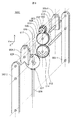
実施の形態に係る試料ホルダの第一の実施例(実施例1)について図2から図4を用いて説明する。図2に実施例1に係る試料ホルダの先端部の上面図を示す。図2(A)は観察領域のx軸周りの回転シリーズ像を取得するときの試料ホルダの状態例を示し、図2(B)は観察領域のy軸周りの回転シリーズ像を取得するときの試料ホルダの状態例を示している。試料003が図2(A)と図2(B)で90°回転している。図3は実施例1に係る試料ホルダの先端部の構成図である。図3には保持筒001および試料003を図示していない。
A first example (Example 1) of the sample holder according to the embodiment will be described with reference to FIGS. FIG. 2 shows a top view of the tip portion of the sample holder according to the first embodiment. 2A shows an example of the state of the sample holder when acquiring a rotation series image around the x-axis of the observation region, and FIG. 2B shows a case when acquiring a rotation series image around the y-axis of the observation region. The example of a state of a sample holder is shown. The
実施例1に係る試料ホルダ100Aは、保持筒001と、保持筒001の内部に配置された保持棒002と、保持棒002の先端に配置された第2の回転冶具009と、第2の回転冶具009の先端に配置された第1の回転冶具006と、第1の回転冶具006の外周に試料を設置させる針状ステージホルダ005と、針状ステージ004と、を備える。試料ホルダ100Aの先端を透過電子顕微鏡等の荷電粒子線装置の試料室(真空容器)に挿入した際、荷電粒子線装置に搭載されている試料ホルダ移動機構と接触するのは保持筒001である。なお、試料ホルダ100Aの挿入方向をX方向に設定する。保持筒001には荷電粒子線が通過するための開口部110が設けられており、試料003はその開口部110に設置されている。試料ホルダ100Aは荷電粒子線に対する試料の位置と角度を設定する。第1の回転軸RA1はX方向に平行であり、荷電粒子線の照射軸はZ方向に平行であるので、第1の回転軸RA1は荷電粒子線の照射軸に垂直である。なお、試料003の大きさは、例えば、直径が100〜300nm程度、長さが1〜5μm程度である。試料003の直径は透過像が得られる細さであればよい。試料ホルダ100Aの幅(Y方向の長さ)は、例えば7mm程度、開口部110の幅(Y方向の長さ)は、例えば4mm程度である。
The
保持棒002は、保持筒001とは独立に、保持筒001内で、第1の回転軸RA1の周りに−180°から+180°回転可能である。保持棒002の回転を制御する第1の回転制御部(図示せず)には、例えば保持棒002を回転させるパルスモータを用いる。第1の回転制御部は試料室の外部(常圧内)に配置するのが好ましい。また、第1の回転冶具006は保持筒001内で、第1の回転軸RA1と直交する第2の回転軸RA2の周りに少なくとも90°の回転が可能である。
The holding
試料003は針状ステージ004の先端部に設置されている。針状ステージ004は針状ステージホルダ005に挿入されており、ピンセット等を用いて着脱することが可能である。針状ステージホルダ005は第一回転冶具006に固定されている。第一回転冶具006と第一歯車007は固定されており、第一回転冶具006が第一歯車軸008を回転軸として回転した際は第一歯車007も同様に回転する。
The
本実施例は試料003を移動させる動力として、試料ホルダに直進運動が導入された場合の例である。スライド棒019が延伸方向(X方向)に直進運動する。ワイヤー018は第一滑車015につながっている。ワイヤー018の一部がスライド棒019に固定されており、スライド棒019の直進運動によって第一滑車(回転体)015が回転する。スライド棒019の移動には、例えばリニアクチュエータ(図示せず)を用いる。リニアクチュエータは試料室の外部(常圧内)に配置するのが好ましい。ワイヤー018およびスライド棒019が動力部POに相当する。
This embodiment is an example in which a straight movement is introduced into the sample holder as power for moving the
第一滑車015および第三歯車012は保持棒002内に設置されており、第三歯車軸013を回転軸として回転することができる。保持棒002は複数の部品002−1、002−2に分け、第一滑車015および第三歯車012等を両サイドから挟み込む構造になっている。第一滑車015には回転面に対して下(第1面)に第一ピン016が、上(第2面)に第二ピン017が取り付けられている。なお、+Z方向を上、−Z方向を下としている(以下の説明でも同じ)。第一滑車015、第一ピン016、第二ピン017が動力分離器PDに相当する。第一滑車015の回転を、第一ピン016につながっている回転運動伝達機構ROと、第二ピン017につながっている直進運動伝達機構PTを使って、第一回転冶具006の回転運動と直進運動に分離する。
The
第三歯車012は第一ピン遊動長孔014を有しており、第一ピン016は第一ピン遊動長孔014に挿入されている。第一滑車015の回転によって第一ピン016も回転する。第一ピン016が第一ピン遊動長孔014の端部に当たると、第三歯車012は第一滑車015と供に回転する。第一ピン016が第一ピン遊動長孔014の端部に接していないときは、第一滑車015の回転は第三歯車012に伝達されない。
The
第二歯車010は、第二歯車軸011を回転軸として回転することができる。第三歯車012の回転は第二歯車010に伝達され、さらに第一歯車007に伝達される。
第一歯車007は、試料003が取り付けられている第一回転冶具006に固定されているため、第一ピン016の回転は第一回転冶具006の回転を導く。動力分離器PDの一部である第一ピン016によって分離された動力が第一回転冶具006を回転させるまでの機構が回転運動伝達機構ROに相当する。また、第一回転冶具006の回転は図1に示した第2の回転軸RA2周りの回転運動に相当する。すなわち、第一歯車軸008が第2の回転軸RA2に相当する。
The
Since the
第二回転冶具009は複数の部品009−1、009−2に分け、第一回転治具006等を挟み込む構造になっている。第二回転冶具009の部品009−2にはV字溝021が設けられており、第二ピン017がV字溝に入るようになっている。第一滑車015の回転によって第二ピン017が回転し、第二ピン017がV字溝021に当たると、第二回転冶具009は第二ピン017に押されて第二歯車軸011を回転軸として回転する。第二ピン017がV字溝021から離れると、第二回転冶具009の回転は止まる。
第二回転冶具009のV字溝021と反対側の端部には第一回転冶具006が設置されている。第二ピン017によって第二回転冶具009が回転すると、第一回転冶具006はY方向にスライドすることになる。動力分離器PDの一部である第二ピン017によって分離された動力が第一回転冶具006をスライドさせるまでの機構が直進運動伝達機構PTに相当する。また、第一回転冶具006のスライドは図1に示した第2の回転軸の直進運動に相当する。
The second
A first
第一回転冶具006の回転および第一回転冶具006のスライドするタイミングは、第一ピン016と第二ピン017の第一滑車015上の配置、第一ピン遊動長孔014の長さによって決定することができる。
The timing of the rotation of the first
各部品の動きについて図4および図5で説明する。図4および図5は実施例1に係る試料ホルダの先端部分の上面図である。保持棒002、第一滑車015は図示していない。開始時は図4(A)のように、第一回転冶具006、第二回転冶具009、はX方向を向いており、第一ピン016、第二ピン017は試料ホルダ100Aの中心線(第1の回転軸RA1)上にあるとする。第一滑車015が反時計回りに回転すると、第二回転冶具009のV字溝021に入った第二ピン017によって、第二回転冶具009は第二歯車軸011を回転軸として時計回りに回転する。その結果、第一回転冶具006は−Y方向にスライドする(図4(B))。第二ピン017がV字溝021から離れると、第一回転冶具006のスライドは止まる。さらに第一滑車015が反時計回りに回転すると、第一ピン016は第一ピン遊動長孔014の端部に達し、第三歯車012が反時計回りに回転する(図4(C))。第三歯車012の回転は第二歯車010、第一歯車007に伝わり、第一回転冶具006が第一歯車軸008を回転軸として反時計回りに回転する。針状ステージ004の中心軸(円柱状の試料003の長軸)がX軸に対して+45°傾いたとき、第一滑車015の回転を止める(図4(D))。図4(D)の状態で、上記第1の回転制御部によって試料003を第1の回転軸RA1の周りに−180°から+180°回転させる。
The movement of each component will be described with reference to FIGS. 4 and 5 are top views of the tip portion of the sample holder according to the first embodiment. The holding
次に第一滑車015を時計回りに回転させる。同様に時計回りに回転する第二ピン017は第二回転冶具009のV字溝021に入る(図5(A))。さらに第一滑車015が回転すると、第二ピン017によって第二回転冶具009は第二歯車軸011を回転軸として反時計回りに回転する。その結果、第一回転冶具006は+Y方向にスライドする(図5(B))。第二ピン017がV字溝021から離れると、第一回転冶具006のスライドは止まる。さらに第一滑車015が時計回りに回転すると、第一ピン016は第一ピン遊動長孔014の端部に達し、第三歯車012が時計回りに回転する。第三歯車012の回転は第二歯車010、第一歯車007に伝わり、第一回転冶具006が第一歯車軸008を回転軸として時計回りに回転する。針状ステージ004の中心軸がX軸に対して−45°傾いたとき、第一滑車015の回転を止める(図5(C)))。図5(C)の状態で、上記第1の回転制御部によって試料003を第1の回転軸RA1の周りに−180°から+180°回転させる。
Next, the
最後に、撮影手順を図4、図5および図15を用いて説明する。図15は実施例1に係る試料ホルダを用いる荷電粒子線装置における撮影手順を説明するためのフロー図である。撮影手順(観察方法)は、4つの手順から構成される。(a)荷電粒子線軸と直交する第1の回転軸と試料のx軸とを平行に設定する(ステップS01)。(b)第1の回転角度制御部を用い、観察領域のx軸周り−180°から+180°の回転シリーズ像を撮影する(ステップS02)。(c)第1の回転軸と試料のy軸とを平行に設定する(ステップS03)。(d)第1の回転制御部を用い、観察領域のy軸周り−180°から+180°の回転シリーズ像を撮影する(ステップS04)。 Finally, the photographing procedure will be described with reference to FIGS. FIG. 15 is a flowchart for explaining an imaging procedure in the charged particle beam apparatus using the sample holder according to the first embodiment. The photographing procedure (observation method) is composed of four procedures. (A) The first rotation axis orthogonal to the charged particle beam axis and the x-axis of the sample are set in parallel (step S01). (B) Using the first rotation angle control unit, take a rotation series image of −180 ° to + 180 ° around the x-axis of the observation region (step S02). (C) The first rotation axis and the y-axis of the sample are set in parallel (step S03). (D) Using the first rotation control unit, take a rotation series image of −180 ° to + 180 ° around the y-axis of the observation region (step S04).
まず、(a)の手順(ステップS01)の詳細を説明する。試料ホルダ100Aに試料003が装着された状態から開始する。図4(A)から図4(D)に示すように、直線運動伝達機構PTと回転運動伝達機構ROをも用いて、針状ステージ004の長軸(円柱状の試料003の長軸)と第1の回転軸RA1とのなす角がほぼ+45°になるようにし、試料003をほぼ第1の回転軸RA1上に移動させる。その後、試料ホルダ003を試料室に挿入する。試料室内での試料003の位置を確認し、まず、第2の回転軸RA2が荷電粒子線光軸とできるだけ平行になるように調整する。こうして調整された試料003において、試料003に固定されたxyz方向は、筐体に固定されたXYZ方向とほぼ一致する。なお、このときの試料003の透過像を幾つかの倍率で撮影しておくと、後で試料003のy軸を第1の回転軸RA1とできるだけ平行に設定するときの確認に用いることができる。なお、試料ホルダ100Aを試料室に挿入する時期は、試料003が試料ホルダ100Aに装着された後であれば、試料ホルダ100Aが図4(A)から図4(D)に示す間のいずれであってもよい。
First, the details of the procedure (a) (step S01) will be described. The process starts from a state in which the
そして、(b)の手順(ステップS02)の詳細を説明する。第1の回転角度制御部を用いて、支持棒002を第1の回転軸RA1の周りに回転させ、観察領域のx軸周りの−180°から+180°の回転シリーズ像を撮影する。例えば、第1の回転軸RA1の周りの回転は10°ずつ行い、その都度試料003を撮影して、36個の回転シリーズ像を得る。
Details of the procedure (b) (step S02) will be described. Using the first rotation angle control unit, the
次に(c)の手順(ステップS03)の詳細を説明する。試料ホルダ100Aを試料室に挿入したまま、図5(A)から図5(C)に示すように、直線運動伝達機構PTと回転運動伝達機構ROをも用いて、針状ステージ004の長軸(円柱状の試料003の長軸)と第1の回転軸RA1とのなす角がほぼ−45°になるようにし、試料003をほぼ第1の回転軸RA1上に移動させる。試料室内での試料003の位置を確認した後、ステップS03と同じく、第2の回転軸RA2が荷電粒子線光軸とできるだけ平行になるように調整する。そして、試料003のy軸が第1の回転軸RA1とできるだけ平行になるように、回転運動伝達機構ROを用いて微調整する。微調整において、ステップS01で撮影した画像を参照画像にし、現設定で撮影された画像の回転角度を画像処理で測定し、ステップS01の状態の第1の回転治具006に対しステップS03の第1の回転治具006の回転角度が90°になるように調整する。
Next, details of the procedure (c) (step S03) will be described. While the
(d)の手順(ステップS04)の詳細を説明する。第1の回転角度制御部を用いて、支持棒002を第1の回転軸RA1の周りに回転させ、観察領域のy軸周りの−180°から+180°の回転シリーズ像を撮影する。ステップS02と同様に、例えば、第1の回転軸RA1の周りの回転は10°ずつ行い、その都度試料003を撮影して、36個の回転シリーズ像を得る。
Details of the procedure (d) (step S04) will be described. Using the first rotation angle control unit, the
なお、撮影手順は、ステップS03、ステップS04、ステップS01、ステップS02の順で行ってもよい。 The shooting procedure may be performed in the order of step S03, step S04, step S01, and step S02.
取得した観察領域のx軸周りとy軸周りの回転シリーズ像から非特許文献1に記載の技術を用いて3次元磁場構造を再構成する。 A three-dimensional magnetic field structure is reconstructed using the technique described in Non-Patent Document 1 from the rotation series images around the x-axis and y-axis of the acquired observation region.
本実施例によれば、試料ホルダ内に第一回転治具を直線運動させる機構を設けているので、試料ホルダを搭載するステージを改造する必要がない。特許文献1または特許文献2のように試料ホルダ内に追加のスペースを確保する必要がない。また、本実施例によれば、x軸周りの回転シリーズ像とy軸周りの回転シリーズ像を取得する間、試料を大気中に曝すことなく一連の観察を行うことができる。観察の途中で試料を取り出す場合、荷電粒子線装置を停止して試料を取り出し、試料の再挿入後、再度装置を稼働させる必要がある。しかし、本実施例では観察の途中で試料を取り出す必要がない。その結果、電磁場構造解析における観察に要する時間を大幅に短縮することができるようになる。また、観察途中に大気に曝されることで酸化して材料特性が変化してしまう試料も観察することができるようになる。また、試料を冷却あるいは加熱しながら観察する場合も、室温に戻してから大気に取り出す必要がなくなるため、観察時間の大幅短縮を図れ、温度変化による材料特性の変化を懸念する必要もなくなる。その結果、観察対象試料も拡大させることができる。 According to the present embodiment, since the mechanism for linearly moving the first rotating jig is provided in the sample holder, there is no need to modify the stage on which the sample holder is mounted. Unlike Patent Document 1 or Patent Document 2, it is not necessary to secure an additional space in the sample holder. Further, according to the present embodiment, a series of observations can be performed without exposing the sample to the atmosphere while acquiring a rotation series image around the x axis and a rotation series image around the y axis. When taking out a sample in the middle of observation, it is necessary to stop the charged particle beam apparatus, take out the sample, and operate the apparatus again after reinserting the sample. However, in this embodiment, it is not necessary to take out a sample during observation. As a result, the time required for observation in the electromagnetic field structure analysis can be greatly reduced. In addition, it is possible to observe a sample that is oxidized and exposed to the atmosphere during the observation to change the material characteristics. Also, when observing a sample while cooling or heating, it is not necessary to return to room temperature and take it out to the atmosphere, so that the observation time can be greatly shortened, and there is no need to worry about changes in material properties due to temperature changes. As a result, the observation target sample can also be enlarged.
また、実施例1に係る試料ホルダは、試料に対して、第1の回転軸RA1の周りの−180°から+180°回転と、第1の回転軸に直交する方向の第2の回転軸の周りのほぼ−90°から+90°回転を与えることができる。つまり試料を半天球内のあらゆる方位から観察することが可能である。透過電子顕微鏡だけでなく走査電子顕微鏡に対しても実施例1に係る試料ホルダを適用すれば、試料の詳細な立体形状を得ることも可能になる。 In addition, the sample holder according to the first embodiment has a rotation of −180 ° to + 180 ° around the first rotation axis RA1 with respect to the sample, and a second rotation axis in a direction perpendicular to the first rotation axis. Around -90 ° to + 90 ° rotation around can be provided. That is, it is possible to observe the sample from all directions in the hemisphere. If the sample holder according to the first embodiment is applied not only to the transmission electron microscope but also to the scanning electron microscope, it is possible to obtain a detailed three-dimensional shape of the sample.
実施例1では動力分離器として2つのピンと滑車を用いており、部品の加工も比較的容易である。実施の形態に係る試料ホルダの第二の実施例(実施例2)では動力分離器として2つの欠歯歯車と滑車を用いた例を示す。 In the first embodiment, two pins and a pulley are used as the power separator, and the processing of the parts is relatively easy. In the second example (Example 2) of the sample holder according to the embodiment, an example in which two partial gears and a pulley are used as a power separator is shown.
実施例2について図6および図7を用いて説明する。図6は実施例2に係る試料ホルダの先端部の構成図である。図7は実施例2に係る試料ホルダの動力分離器に相当する2つの欠歯歯車と第一滑車015の拡大図である。実施例2に係る試料ホルダ100Bの第一滑車015には回転面に対して下(第1面)に第一欠歯歯車022が、上(第2面)に第二欠歯歯車023が取り付けられている。第一滑車015、第一欠歯歯車022、第二欠歯歯車023が動力分離器に相当する。第一欠歯歯車022、第二欠歯歯車023は第一滑車015に固定されており、第一滑車軸025を回転軸として回転することができる。第一滑車015の回転によって第一欠歯歯車022も回転する。第一欠歯歯車022の歯は第二歯車010と噛み合うようになっている。第一欠歯歯車022が回転し、第一欠歯歯車022の歯が第二歯車010と噛み合うと、第一欠歯歯車022の回転は第二歯車010に伝達される。第一欠歯歯車022の欠歯領域では、第一欠歯歯車022の回転は第二歯車010に伝達されない。第二歯車010の回転は第一歯車007に伝達され、第一回転冶具006が回転する。
A second embodiment will be described with reference to FIGS. 6 and 7. FIG. 6 is a configuration diagram of the distal end portion of the sample holder according to the second embodiment. FIG. 7 is an enlarged view of two toothless gears and a
第二回転冶具009は部品009−1、009−3と第四歯車024を有している。第四歯車024は第二回転冶具009の部品009−3に固定されており、第二歯車軸011を回転軸として回転することができる。第一滑車015の回転によって第二欠歯歯車023も回転する。第二欠歯歯車023の歯は第四歯車024と噛み合うようになっている。第二欠歯歯車023が回転し、第一欠歯歯車023の歯が第四歯車024と噛み合うと、第二欠歯歯車023の回転は第四歯車024に伝達される。第二欠歯歯車023の欠歯領域では、第二欠歯歯車023の回転は第四歯車024に伝達されない。第二欠歯歯車023によって第二回転冶具009が回転すると、第一回転冶具006はY方向にスライドすることになる。
The second
第一回転冶具006の回転および第一回転冶具006のスライドするタイミングは、第一欠歯歯車022と第二欠歯歯車023の欠歯領域の長さおよび第一滑車015上の配置によって決定することができる。
The timing of the rotation of the first
第一回転冶具006の詳細な動きについては実施例1と同じであるので、撮影(観察)手順などの説明は省略する。
Since the detailed movement of the first
実施例1では動力分離器に入力する動力として、スライド棒の直進運動の例を示した。実施の形態に係る試料ホルダの第三の実施例(実施例3)では動力分離器に回転運動を入力した例を示す。ワイヤーを用いていないので、ワイヤーが切断する可能性がなく、ワイヤーと滑車が滑ることがないため動作の再現性も良くなる。 In the first embodiment, as an example of the power input to the power separator, the linear movement of the slide bar is shown. In the third example (Example 3) of the sample holder according to the embodiment, an example in which rotational motion is input to the power separator is shown. Since the wire is not used, there is no possibility of the wire being cut, and the reproducibility of the operation is improved because the wire and the pulley do not slip.
実施例3について図8および図9を用いて説明する。図8は実施例3に係る試料ホルダの先端部の構成図である。図9は実施例3に係る試料ホルダの先端部分の側面図である。実施例3に係る試料ホルダ100Cの動力分離器は第一かさ歯車(回転体)026、第一ピン016、第二ピン017から構成されている。動力分離器に入力される動力は、第二かさ歯車軸028の回転運動である。第二かさ歯車軸028の先端には第二かさ歯車027が取り付けられており、第二かさ歯車軸028の回転によって第一かさ歯車026が回転する。
A third embodiment will be described with reference to FIGS. 8 and 9. FIG. 8 is a configuration diagram of the tip portion of the sample holder according to the third embodiment. FIG. 9 is a side view of the tip portion of the sample holder according to the third embodiment. The power separator of the
第一かさ歯車026には回転面に対して下に第一ピン016が、上に第二ピン017が取り付けられている。第一ピン016、第二ピン017の役割、および各部品の動きについては実施例1と同じであるので、撮影手順などの説明は省略する。
A
実施例3では動力分離器に入力する動力として、かさ歯車軸の回転運動の例を示した。実施の形態に係る試料ホルダの第四の実施例(実施例4)では動力分離器に回転運動を入力した別の例を示す。 In the third embodiment, an example of the rotational motion of the bevel gear shaft is shown as the power input to the power separator. In the fourth example (Example 4) of the sample holder according to the embodiment, another example in which the rotational motion is input to the power separator is shown.
実施例4について図10を用いて説明する。図10は実施例4に係る試料ホルダの先端部の構成図である。実施例4に係る試料ホルダ100Dの動力分離器はピン付き歯車029、第一ピン016、第二ピン017から構成されている。動力分離器に入力される動力は、ウォームホイル軸031の回転運動である。ウォームホイル軸031の先端にはウォームホイル030が取り付けられており、ウォームホイル軸031の回転によってピン付き歯車029が回転する。
Example 4 will be described with reference to FIG. FIG. 10 is a configuration diagram of the tip portion of the sample holder according to the fourth embodiment. The power separator of the
ピン付き歯車029には回転面に対して下に第一ピン016が、上に第二ピン017が取り付けられている。第一ピン016、第二ピン017の役割、および各部品の動きについては実施例1と同じであるので、撮影手順などの説明は省略する。
A
実施の形態に係る試料ホルダの第五の実施例(実施例5)では、実施例2に示した欠歯歯車を用いた動力分離器と、実施例3に示した動力分離器にかさ歯車軸の回転運動を入力した実施例を組み合わせた実施例を示す。 In the fifth example (Example 5) of the sample holder according to the embodiment, the power separator using the partial gear shown in Example 2 and the bevel gear shaft in the power separator shown in Example 3 are used. The Example which combined the Example which input these rotational motions is shown.
実施例5について図11を用いて説明する。図11は実施例5に係る試料ホルダの先端部の構成図である。実施例5に係る試料ホルダ100Eの動力分離器は第一かさ歯車026、第一欠歯歯車022、第二欠歯歯車023から構成されている。第一欠歯歯車022は第一かさ歯車026に隠れているため図示されていない。
A fifth embodiment will be described with reference to FIG. FIG. 11 is a configuration diagram of the distal end portion of the sample holder according to the fifth embodiment. The power separator of the
動力分離器に入力される動力は、第二かさ歯車軸028の回転運動である。第二かさ歯車軸028の先端には第二かさ歯車027が取り付けられており、第二かさ歯車軸028の回転によって第一かさ歯車026が回転する。
The power input to the power separator is the rotational motion of the second
第一かさ歯車026には回転面に対して下に第一欠歯歯車022が、上に第二欠歯歯車023が取り付けられている。第一欠歯歯車022、第二欠歯歯車023は第一かさ歯車026に固定されており、第一滑車軸025を回転軸として回転することができる。第一欠歯歯車022、第二欠歯歯車023の役割、および各部品の動きについては実施例2と同じであるので、撮影手順などの説明は省略する。
The
実施の形態に係る試料ホルダの第六の実施例(実施例6)では、実施例2に示した欠歯歯車を用いた動力分離器と、実施例4に示した動力分離器にウォームギアの回転運動を入力した実施例を組み合わせた実施例を示す。 In the sixth example (Example 6) of the sample holder according to the embodiment, the power separator using the partial gear shown in Example 2 and the rotation of the worm gear in the power separator shown in Example 4 are used. The Example which combined the Example which input the exercise | movement is shown.
実施例6について図12を用いて説明する。図12は試料ホルダの先端部の構成図である。実施例6に係る試料ホルダ100Fの動力分離器は第五歯車(回転体)032、第一欠歯歯車022、第二欠歯歯車023から構成されている。第一欠歯歯車022は第五歯車032に隠れているため図示されていない。
Example 6 will be described with reference to FIG. FIG. 12 is a configuration diagram of the tip portion of the sample holder. The power separator of the
動力分離器に入力される動力は、ウォームホイル軸031の回転運動である。ウォームホイル軸031の先端にはウォームホイル030が取り付けられており、ウォームホイル軸031の回転によって第五歯車032が回転する。
The power input to the power separator is the rotational motion of the
第五歯車032は回転面に対して下に第一欠歯歯車022が、上に第二欠歯歯車023が取り付けられている。第一欠歯歯車022、第二欠歯歯車023は第五歯車032に固定されており、第一滑車軸025を回転軸として回転することができる。第一欠歯歯車022、第二欠歯歯車023の役割、および各部品の動きについては実施例2と同じであるので、撮影手順などの説明は省略する。
The
実施例2では動力分離器に2つの欠歯歯車を用いていた。実施の形態に係る試料ホルダの第七の実施例(実施例7)では欠歯歯車の欠歯領域がない場合の例を示す。 In the second embodiment, two partial gears are used for the power separator. In the seventh example (Example 7) of the sample holder according to the embodiment, an example in which there is no missing tooth region of the missing gear is shown.
実施例7について図13を用いて説明する。図13は各部品の動きを示す実施例7に係る試料ホルダ100Gの先端部分の上面図である。本実施例では第一欠歯歯車022、第二欠歯歯車023に欠歯領域はないが、便宜上欠歯歯車と表記する。
Example 7 will be described with reference to FIG. FIG. 13 is a top view of the tip portion of the
第一滑車015が反時計回りに回ると、第二欠歯歯車023も反時計回りに回る。その結果、第二欠歯歯車023に噛み合っている第四歯車024は第二歯車軸011を回転軸として時計回りに回転する。第二回転冶具009は部品009−3が第四歯車024に固定されているため、第二歯車軸011を回転軸として時計回りに回転する。
When the
一方、第一滑車015が反時計周りに回ると、第一欠歯歯車022も反時計回りに回る。その結果、第一欠歯歯車022に噛み合っている第二歯車010は第二歯車軸011を回転軸として時計回りに回転する。さらに、第二歯車010に噛み合っている第一歯車007は第一歯車軸008を回転軸として反時計回りに回転する。試料003を搭載している第一回転冶具006は第一歯車007に固定されているため、第一歯車軸008を回転軸として反時計回りに回転する(図13(B))。
On the other hand, when the
第一滑車015をさらに反時計周りに回転させ、試料003が図13(A)の状態に対して45°傾いたときに第一滑車015の回転を止める(図13(C))。この状態で試料003を第1の回転軸RA1の周りに−180°から+180°回転させ、観察領域のx軸周りの回転シリーズ像を取得する。
The
次に、第一滑車015をさらに時計周りに回転させ、第一の回転軸RA1に対して図13(C)と線対称な状態を作る。その状態で試料003を第1の回転軸RA1の周りに−180°から+180°回転させ、観察領域のy軸周りの回転シリーズ像を取得する。
Next, the
欠歯歯車の欠歯領域を無くした場合、第一滑車015の回転に伴い、第一回転冶具006と第二回転冶具009は同時に回転する。第一回転冶具006の第二回転冶具009の中心軸に対する回転角をαとし、第二回転冶具009の第1の回転軸RA1に対する回転角をβとする。第一歯車軸008から試料003の先端までの距離をa、第二歯車軸011から第一歯車軸008までの距離をbとする。
When the missing tooth region of the missing gear is eliminated, the first
試料003の傾きに伴い、試料003の先端は第1の回転軸RA1上から離れる。Y軸方向のずれ量は
d=b×sinβ−a×sin(α−β) (式1)
となる。図13(C)の状態(α−β=45°)で、試料003の先端が第1の回転軸RA1上に存在するためにはd=0となることから、式1は
β=arcsin(a×sin45°/b) (式2)
となる。
With the inclination of the
It becomes. In the state of FIG. 13C (α−β = 45 °), since the tip of the
It becomes.
αの回転角がβの回転角のn倍になるように歯車のギア比を調整したとすると、α=nβとなるので、図13(C)の状態では、
α−β=nβ−β=45° (式3)
となる。したがって、式2を式3に代入すると
n=45°/β+1=45°/arcsin(a×sin45°/b)+1 (式4)
となる。例えばa=2mm、b=3mmであった場合、αの回転角がβの回転角の2.6倍になるように歯車のギア比を調整しておけば、試料003が45°傾いたとき、試料003の先端を第1の回転軸上に配置することができる。なお、試料003の先端を第1の回転軸上に配置する必要はない。観察領域内に試料003を配置すればよい。
If the gear ratio of the gear is adjusted so that the rotation angle of α is n times the rotation angle of β, α = nβ, so in the state of FIG.
α-β = nβ-β = 45 ° (Formula 3)
It becomes. Therefore, if Equation 2 is substituted into Equation 3, n = 45 ° / β + 1 = 45 ° / arcsin (a × sin45 ° / b) +1 (Equation 4)
It becomes. For example, when a = 2 mm and b = 3 mm, if the gear ratio of the gear is adjusted so that the rotation angle of α is 2.6 times the rotation angle of β, the
以上、本発明者によってなされた発明を実施の形態および実施例に基づき具体的に説明したが、本発明は、上記実施の形態および実施例に限定されるものではなく、種々変更可能であることはいうまでもない。
例えば、実施例1から実施例7に係る試料ホルダの上下が反対の構成であってもよい。すなわち、試料ホルダを上下反対に試料室に挿入するような構成であってもよいし、試料ホルダの一部の部品の構成が上下反対であってもよい。
Although the invention made by the present inventor has been specifically described based on the embodiments and examples, the present invention is not limited to the above-described embodiments and examples, and can be variously changed. Needless to say.
For example, the upper and lower sides of the sample holder according to the first to seventh embodiments may be reversed. In other words, the configuration may be such that the sample holder is inserted into the sample chamber upside down, or the configuration of some parts of the sample holder may be upside down.
001 保持筒
002 保持棒
002−1、002−2 保持棒の部品
003 試料
004 針状ステージ
005 針状ステージホルダ
006 第一回転冶具
007 第一歯車
008 第一歯車軸
009 第二回転冶具
009−1、009−2、009−3 第二回転冶具の部品
010 第二歯車
011 第二歯車軸
012 第三歯車
013 第三歯車軸
014 第一ピン遊動長孔
015 第一滑車
016 第一ピン
017 第二ピン
018 ワイヤー
019 スライド棒
020 第二滑車
021 V字溝
022 第一欠歯歯車
023 第二欠歯歯車
024 第四歯車
025 第一滑車軸
026 第一かさ歯車
027 第二かさ歯車
028 第二かさ歯車軸
029 ピン付き歯車
030 ウォームホイル
031 ウォームホイル軸
032 第五歯車
001
Claims (15)
入力される1つの運動を2つの運動に分離する動力分離器と、
前記動力分離器を保持する保持棒と、
前記動力分離器から生み出される動力を伝え、前記第一回転冶具に直進運動を与える直進運動伝達機構と、
前記動力分離器から生み出される動力を伝え、前記第一回転冶具に回転運動を与える回転運動伝達機構と、
前記動力分離器に運動を与える動力部と、
前記保持棒の延在方向を回転軸として前記第一回転冶具に第1の回転を与える第1の回転制御部と、
を有し、
前記直進運動伝達機構は前記第一回転冶具を前記回転軸に対して線対称の位置にスライドさせる試料ホルダ。 A first rotating jig in which a sample irradiated with a charged particle beam is attached to the tip;
A power separator that separates one input motion into two motions;
A holding rod for holding the power separator;
A linear motion transmission mechanism for transmitting power generated from the power separator and for imparting a linear motion to the first rotary jig;
A rotational motion transmission mechanism that transmits power generated from the power separator and imparts rotational motion to the first rotary jig;
A power unit for imparting motion to the power separator;
A first rotation control unit that applies a first rotation to the first rotary jig with the extending direction of the holding rod as a rotation axis;
I have a,
The linear motion transmitting mechanism specimen holder Ru slide to a position axisymmetric to the first rotating jig with respect to the rotation axis.
前記動力分離器は、
回転体と、
前記回転体の回転面の第1面に取り付けられた第一ピンと、
前記第1面とは反対側の第2面に取り付けられた第二ピンと、
を有しており、
入力される運動を前記回転体の回転運動に変換するようにされる試料ホルダ。 In claim 1,
The power separator is
A rotating body,
A first pin attached to the first surface of the rotating surface of the rotating body;
A second pin attached to the second surface opposite to the first surface;
Have
A sample holder configured to convert an input motion into a rotational motion of the rotating body.
前記回転運動伝達機構は、
前記第一ピンが入る第一ピン遊動長孔を有する第三歯車と、
前記第三歯車の回転を前記第一回転冶具に伝達する第二歯車と、
を有し、
前記第一ピンによって前記第一回転冶具が回転運動するようにされる試料ホルダ。 In claim 2,
The rotational motion transmission mechanism is
A third gear having a first pin floating slot for receiving the first pin;
A second gear for transmitting the rotation of the third gear to the first rotating jig;
Have
A sample holder in which the first rotary jig is rotated by the first pin.
前記直進運動伝達機構は、
一端に前記第二ピンを受けるV字溝と、
その反対側の一端に前記第一回転冶具を保持している第二回転冶具と、
を有し、
前記第二ピンによって前記第二回転冶具が回転することで前記第一回転冶具が直進運動するようにされる試料ホルダ。 In claim 2,
The linear motion transmission mechanism is
A V-shaped groove for receiving the second pin at one end;
A second rotary jig holding the first rotary jig at one end on the opposite side;
Have
A sample holder in which the second rotary jig is rotated by the second pin so that the first rotary jig moves linearly.
前記動力分離器は、前記第一ピンの位置、前記第二ピンの位置および第一ピン遊動長穴の長さを調整することによって、前記第一回転冶具の直進運動と回転運動間の運動位相を制御するようにされる試料ホルダ。 In claim 2,
The power separator adjusts the position of the first pin, the position of the second pin, and the length of the first pin idle slot so that the motion phase between the linear motion and the rotational motion of the first rotary jig A sample holder to be controlled.
前記動力分離器は、
回転体と、
前記回転体の回転面の第1面に取り付けられた第一欠歯歯車と、
前記第1面とは反対側の第2面に取り付けられた第二欠歯歯車と、
を有しており、
入力される運動を前記回転体の回転運動に変換するようにされる試料ホルダ。 In claim 1,
The power separator is
A rotating body,
A first intermittent gear attached to the first surface of the rotating surface of the rotating body;
A second intermittent gear attached to the second surface opposite to the first surface;
Have
A sample holder configured to convert an input motion into a rotational motion of the rotating body.
前記回転運動伝達機構は、前記第一欠歯歯車の回転を前記第一回転冶具に伝達する第二歯車を有し、
前記第一欠歯歯車が回転することで前記第一回転冶具が回転運動するようにされる試料ホルダ。 In claim 6,
The rotational motion transmission mechanism has a second gear that transmits the rotation of the first toothless gear to the first rotary jig,
A sample holder in which the first rotating jig rotates by rotating the first toothless gear.
前記直進運動伝達機構は、第四歯車を保持している第二回転冶具を有し、
前記第二欠歯歯車によって前記第二回転冶具が回転することで前記第一回転冶具が直進運動するようにされる試料ホルダ。 In claim 6,
The linear motion transmission mechanism has a second rotary jig holding a fourth gear,
A sample holder in which the second rotary jig is rotated by the second partial gear so that the first rotary jig moves linearly.
前記動力分離器は、前記第一欠歯歯車と前記第二欠歯歯車の欠歯領域の長さと位置を調整することによって、前記第一回転冶具の直進運動と回転運動間の運動位相を制御するようにされる試料ホルダ。 In claim 6,
The power separator controls the motion phase between the linear motion and the rotational motion of the first rotary jig by adjusting the length and position of the tooth missing region of the first toothless gear and the second toothless gear. Sample holder to be made.
前記荷電粒子線に対する試料の位置と角度を設定する試料ホルダと、
を備え、
前記試料ホルダは
先端部に前記試料が取り付けられる第一回転冶具と、
入力される1つの運動を2つの運動に分離する動力分離器と、
前記動力分離器を保持する保持棒と、
前記動力分離器から生み出される動力を伝え、前記第一回転冶具に直進運動を与える直進運動伝達機構と、
前記動力分離器から生み出される動力を伝え、前記第一回転冶具に回転運動を与える回転運動伝達機構と、
前記動力分離器に運動を与える動力部と、
前記保持棒の延在方向を回転軸として前記第一回転冶具に第1の回転を与える第1の回転制御部と、
を備え、
前記直進運動伝達機構は前記第一回転冶具を前記回転軸に対して線対称の位置にスライドさせる荷電粒子線装置。 An irradiation unit for irradiating the sample with a charged particle beam;
A sample holder for setting the position and angle of the sample with respect to the charged particle beam;
With
The sample holder includes a first rotating jig to which the sample is attached at a tip portion;
A power separator that separates one input motion into two motions;
A holding rod for holding the power separator;
A linear motion transmission mechanism for transmitting power generated from the power separator and for imparting a linear motion to the first rotary jig;
A rotational motion transmission mechanism that transmits power generated from the power separator and imparts rotational motion to the first rotary jig;
A power unit for imparting motion to the power separator;
A first rotation control unit that applies a first rotation to the first rotary jig with the extending direction of the holding rod as a rotation axis;
Equipped with a,
The linear motion transmitting mechanism charged particle beam apparatus Ru slide to a position axisymmetric to the first rotating jig with respect to the rotation axis.
前記動力分離器は、
回転体と、
前記回転体の回転面の第1面に取り付けられた第一ピンまたは第一欠歯歯車と、
前記第1面とは反対側の第2面に取り付けられた第二ピンまたは第二欠歯歯車と、
を有しており、
入力される運動を前記回転体の回転運動に変換するようにされる荷電粒子線装置。 In claim 10,
The power separator is
A rotating body,
A first pin or a first intermittent gear attached to the first surface of the rotating surface of the rotating body;
A second pin or a second intermittent gear attached to the second surface opposite to the first surface;
Have
A charged particle beam apparatus configured to convert an input motion into a rotational motion of the rotating body.
前記回転運動伝達機構は、
前記第一ピンが入る第一ピン遊動長孔を有する第三歯車と、
前記第三歯車の回転を前記第一回転冶具に伝達する第二歯車と、
を備え、
前記第一ピンによって前記第一回転冶具が回転運動するようにされ、
または、
前記回転運動伝達機構は、前記第一欠歯歯車の回転を前記第一回転冶具に伝達する第二歯車を備え、前記第一欠歯歯車が回転することで前記第一回転冶具が回転運動するようにされる、
荷電粒子線装置。 In claim 11,
The rotational motion transmission mechanism is
A third gear having a first pin floating slot for receiving the first pin;
A second gear for transmitting the rotation of the third gear to the first rotating jig;
With
The first rotary jig is caused to rotate by the first pin,
Or
The rotational movement transmission mechanism includes a second gear that transmits the rotation of the first toothless gear to the first rotating jig, and the first rotating jig rotates when the first toothless gear rotates. Done,
Charged particle beam device.
前記直進運動伝達機構は、
一端に前記第二ピンを受けるV字溝と、
その反対側の一端に前記第一回転冶具を保持している第二回転冶具と、
を備え、
前記第二ピンによって前記第二回転冶具が回転することで前記第一回転冶具が直進運動するようにされ、
または、
前記直進運動伝達機構は、第四歯車を保持している第二回転冶具を備え、前記第二欠歯歯車によって前記第二回転冶具が回転することで前記第一回転冶具が直進運動するようにされる、
荷電粒子線装置。 In claim 11,
The linear motion transmission mechanism is
A V-shaped groove for receiving the second pin at one end;
A second rotary jig holding the first rotary jig at one end on the opposite side;
With
The second rotary jig is rotated by the second pin so that the first rotary jig moves linearly,
Or
The linear motion transmission mechanism includes a second rotary jig holding a fourth gear, and the second rotary jig is rotated by the second partial gear so that the first rotary jig linearly moves. To be
Charged particle beam device.
前記動力分離器は、前記第一ピンの位置、前記第二ピンの位置および第一ピン遊動長穴の長さを調整することによって、前記第一回転冶具の直進運動と回転運動間の運動位相を制御するようにされ、
または、
前記動力分離器は、前記第一欠歯歯車と前記第二欠歯歯車の欠歯領域の長さと位置を調整することによって、前記第一回転冶具の直進運動と回転運動間の運動位相を制御するようにされる、
荷電粒子線装置。 In claim 12,
The power separator adjusts the position of the first pin, the position of the second pin, and the length of the first pin idle slot so that the motion phase between the linear motion and the rotational motion of the first rotary jig Is to control and
Or
The power separator controls the motion phase between the linear motion and the rotational motion of the first rotary jig by adjusting the length and position of the tooth missing region of the first toothless gear and the second toothless gear. To be,
Charged particle beam device.
(a)前記荷電粒子線の照射軸と直交する方向を第1の回転軸と前記試料のx軸とを平行に設定し、前記試料を観察領域に配置する工程と、
(b)前記第1の回転軸の周りに第1の回転を前記試料に与え、前記観察領域のx軸周り−180°から+180°の回転シリーズ像を得る工程と、
(c)前記第1の回転軸と前記試料のy軸とを平行に設定し、前記試料を前記観察領域に配置する工程と、
(d)前記第1の回転軸の周りに第1の回転を前記試料に与え、前記観察領域のy軸周り−180°から+180°の回転シリーズ像を得る工程と、
を有し、
前記(a)工程は、
(a1)入力される1つの動力を分離し、第一回転治具に回転運動を与えることにより、前記試料に第2の回転を与える工程と、
(a2)前記入力される1つの動力を分離し、前記第一回転治具に直進運動を与えることにより、前記試料を第1の方向に移動させる工程と、
を有し、
前記(c)工程は、
(c1)入力される1つの動力を分離し、前記第一回転治具に回転運動を与えることにより、前記試料に第3の回転を与える工程と、
(c2)前記入力される1つの動力を分離し、前記第一回転治具に直進運動を与えることにより、前記試料を第2の方向に移動させる工程と、
を有する、
観察方法。 An observation method in a charged particle beam apparatus comprising: an irradiation unit that irradiates a sample with a charged particle beam; and a sample holder that sets a position and an angle of the sample with respect to the charged particle beam.
(A) setting a direction orthogonal to the irradiation axis of the charged particle beam so that the first rotation axis and the x-axis of the sample are parallel, and arranging the sample in an observation region;
(B) applying a first rotation to the sample around the first rotation axis to obtain a rotation series image of −180 ° to + 180 ° around the x-axis of the observation region;
(C) setting the first rotation axis and the y-axis of the sample in parallel, and placing the sample in the observation region;
(D) applying a first rotation to the sample around the first rotation axis to obtain a rotation series image of −180 ° to + 180 ° around the y axis of the observation region;
Have
The step (a)
(A1) Separating one input power and giving a rotational movement to the first rotating jig to give a second rotation to the sample;
(A2) separating the one input power and moving the sample in a first direction by giving a straight movement to the first rotating jig;
Have
The step (c)
(C1) separating one input power and giving a rotational movement to the first rotating jig to give a third rotation to the sample;
(C2) separating the one input power and moving the sample in the second direction by giving a straight movement to the first rotating jig;
Having
Observation method.
Priority Applications (3)
| Application Number | Priority Date | Filing Date | Title |
|---|---|---|---|
| JP2014152939A JP6308904B2 (en) | 2014-07-28 | 2014-07-28 | Sample holder, charged particle beam apparatus, and observation method |
| DE102015213764.3A DE102015213764B4 (en) | 2014-07-28 | 2015-07-22 | Sample holder, charged particle beam apparatus and observation method |
| US14/810,673 US9773640B2 (en) | 2014-07-28 | 2015-07-28 | Sample holder, charged particle beam apparatus, and observation method |
Applications Claiming Priority (1)
| Application Number | Priority Date | Filing Date | Title |
|---|---|---|---|
| JP2014152939A JP6308904B2 (en) | 2014-07-28 | 2014-07-28 | Sample holder, charged particle beam apparatus, and observation method |
Publications (3)
| Publication Number | Publication Date |
|---|---|
| JP2016031805A JP2016031805A (en) | 2016-03-07 |
| JP2016031805A5 JP2016031805A5 (en) | 2016-11-17 |
| JP6308904B2 true JP6308904B2 (en) | 2018-04-11 |
Family
ID=55065779
Family Applications (1)
| Application Number | Title | Priority Date | Filing Date |
|---|---|---|---|
| JP2014152939A Active JP6308904B2 (en) | 2014-07-28 | 2014-07-28 | Sample holder, charged particle beam apparatus, and observation method |
Country Status (3)
| Country | Link |
|---|---|
| US (1) | US9773640B2 (en) |
| JP (1) | JP6308904B2 (en) |
| DE (1) | DE102015213764B4 (en) |
Families Citing this family (2)
| Publication number | Priority date | Publication date | Assignee | Title |
|---|---|---|---|---|
| US9734985B2 (en) * | 2015-07-01 | 2017-08-15 | Kabushiki Kaisha Toshiba | Analytical apparatus, sample holder and analytical method |
| DE102015215323A1 (en) * | 2015-08-11 | 2017-02-16 | Georg-August-Universität Göttingen Stiftung Öffentlichen Rechts | Technique for tomographic image acquisition |
Family Cites Families (9)
| Publication number | Priority date | Publication date | Assignee | Title |
|---|---|---|---|---|
| US5153434A (en) | 1990-05-18 | 1992-10-06 | Hitachi, Ltd. | Electron microscope and method for observing microscopic image |
| US6410925B1 (en) | 2000-07-31 | 2002-06-25 | Gatan, Inc. | Single tilt rotation cryotransfer holder for electron microscopes |
| JP2008107226A (en) * | 2006-10-26 | 2008-05-08 | Jeol Ltd | Sample preparing system |
| JP5268324B2 (en) | 2007-10-29 | 2013-08-21 | 株式会社日立ハイテクノロジーズ | Charged particle beam microscope and microscope method |
| DE102009001587A1 (en) * | 2009-01-06 | 2010-07-08 | Carl Zeiss Nts Gmbh | Method for adjusting operating parameter of particle radiation device, involves providing sample holder with sample receptacle for receiving reference sample |
| JP5250470B2 (en) * | 2009-04-22 | 2013-07-31 | 株式会社日立ハイテクノロジーズ | Sample holder, method of using the sample holder, and charged particle device |
| US8089053B1 (en) * | 2009-11-10 | 2012-01-03 | Dudley Finch | Dynamically tilting specimen holder for stereo and tomographic imaging in a transmission electron microscope using a combination of micro electro mechanical systems (MEMS) and piezoelectric transducers (PZTs) |
| JP5403560B2 (en) * | 2010-11-17 | 2014-01-29 | コリア ベイシック サイエンス インスティテュート | Specimen holder capable of 3-axis drive for observing and analyzing specimens from more than three directions in a transmission electron microscope |
| JP5883658B2 (en) * | 2012-01-20 | 2016-03-15 | 株式会社日立ハイテクノロジーズ | Charged particle beam microscope, charged particle beam microscope sample holder, and charged particle beam microscope method |
-
2014
- 2014-07-28 JP JP2014152939A patent/JP6308904B2/en active Active
-
2015
- 2015-07-22 DE DE102015213764.3A patent/DE102015213764B4/en active Active
- 2015-07-28 US US14/810,673 patent/US9773640B2/en active Active
Also Published As
| Publication number | Publication date |
|---|---|
| DE102015213764A1 (en) | 2016-01-28 |
| US20160035535A1 (en) | 2016-02-04 |
| US9773640B2 (en) | 2017-09-26 |
| JP2016031805A (en) | 2016-03-07 |
| DE102015213764B4 (en) | 2018-05-30 |
Similar Documents
| Publication | Publication Date | Title |
|---|---|---|
| EP2811288B1 (en) | Method for electron tomography | |
| US9099281B2 (en) | Charged particle radiation apparatus, and method for displaying three-dimensional information in charged particle radiation apparatus | |
| US8963102B2 (en) | Charged particle beam microscope, sample holder for charged particle beam microscope, and charged particle beam microscopy | |
| KR20170108805A (en) | Focused ion beam apparatus | |
| JP2008270056A (en) | Scanning transmission electron microscope | |
| EP2402976A1 (en) | Method of electron diffraction tomography | |
| JP6308904B2 (en) | Sample holder, charged particle beam apparatus, and observation method | |
| JP7431016B2 (en) | How to image a sample using an electron microscope | |
| US20160020065A1 (en) | Tem sample mounting geometry | |
| CN112189134B (en) | X-ray imaging device | |
| WO2014195998A1 (en) | Charged particle microscope, sample holder for charged particle microscope and charged particle microscopy method | |
| KR101604055B1 (en) | Electron Microscope Stage With 6-Axis Movement Using SEM Stage | |
| JP2008188279A (en) | X-ray ct apparatus | |
| JP7257549B2 (en) | Diffractometer for charged particle crystallography | |
| JP2019067555A (en) | Phase difference transmission electron microscope device | |
| CN110389144A (en) | The method for producing TEM sample | |
| JP6376698B2 (en) | X-ray inspection apparatus and method for adjusting X-ray inspection apparatus | |
| JP2008107124A (en) | Radiation inspection system, radiation inspection method and radiation inspection program | |
| JP6636839B2 (en) | Sample holder, focused ion beam device | |
| JP2013076735A (en) | Image capture device and image capture method | |
| JP2009070604A (en) | Sample support stage for observing three-dimensional structure, protractor and three-dimensional structure observing method | |
| EP3125270A1 (en) | Tem sample mounting geometry | |
| JP2015170504A (en) | X-ray generator and x-ray imaging apparatus | |
| JP2019067554A (en) | Phase difference sweep transmission electron microscope device | |
| WO2016051588A1 (en) | Spatial-structure observation/processing method and apparatus |
Legal Events
| Date | Code | Title | Description |
|---|---|---|---|
| A521 | Request for written amendment filed |
Free format text: JAPANESE INTERMEDIATE CODE: A523 Effective date: 20160928 |
|
| A621 | Written request for application examination |
Free format text: JAPANESE INTERMEDIATE CODE: A621 Effective date: 20160928 |
|
| A131 | Notification of reasons for refusal |
Free format text: JAPANESE INTERMEDIATE CODE: A131 Effective date: 20170829 |
|
| A521 | Request for written amendment filed |
Free format text: JAPANESE INTERMEDIATE CODE: A523 Effective date: 20171024 |
|
| TRDD | Decision of grant or rejection written | ||
| A01 | Written decision to grant a patent or to grant a registration (utility model) |
Free format text: JAPANESE INTERMEDIATE CODE: A01 Effective date: 20180213 |
|
| A61 | First payment of annual fees (during grant procedure) |
Free format text: JAPANESE INTERMEDIATE CODE: A61 Effective date: 20180313 |
|
| R150 | Certificate of patent or registration of utility model |
Ref document number: 6308904 Country of ref document: JP Free format text: JAPANESE INTERMEDIATE CODE: R150 |