JP6301113B2 - Ultrasonic diagnostic apparatus and program for ultrasonic diagnostic apparatus - Google Patents
Ultrasonic diagnostic apparatus and program for ultrasonic diagnostic apparatus Download PDFInfo
- Publication number
- JP6301113B2 JP6301113B2 JP2013238907A JP2013238907A JP6301113B2 JP 6301113 B2 JP6301113 B2 JP 6301113B2 JP 2013238907 A JP2013238907 A JP 2013238907A JP 2013238907 A JP2013238907 A JP 2013238907A JP 6301113 B2 JP6301113 B2 JP 6301113B2
- Authority
- JP
- Japan
- Prior art keywords
- scan
- ultrasonic
- image data
- dimensional
- contrast
- Prior art date
- Legal status (The legal status is an assumption and is not a legal conclusion. Google has not performed a legal analysis and makes no representation as to the accuracy of the status listed.)
- Active
Links
Images


Classifications
-
- A—HUMAN NECESSITIES
- A61—MEDICAL OR VETERINARY SCIENCE; HYGIENE
- A61B—DIAGNOSIS; SURGERY; IDENTIFICATION
- A61B8/00—Diagnosis using ultrasonic, sonic or infrasonic waves
- A61B8/48—Diagnostic techniques
- A61B8/481—Diagnostic techniques involving the use of contrast agent, e.g. microbubbles introduced into the bloodstream
-
- A—HUMAN NECESSITIES
- A61—MEDICAL OR VETERINARY SCIENCE; HYGIENE
- A61B—DIAGNOSIS; SURGERY; IDENTIFICATION
- A61B8/00—Diagnosis using ultrasonic, sonic or infrasonic waves
- A61B8/48—Diagnostic techniques
- A61B8/483—Diagnostic techniques involving the acquisition of a 3D volume of data
-
- A—HUMAN NECESSITIES
- A61—MEDICAL OR VETERINARY SCIENCE; HYGIENE
- A61B—DIAGNOSIS; SURGERY; IDENTIFICATION
- A61B8/00—Diagnosis using ultrasonic, sonic or infrasonic waves
- A61B8/48—Diagnostic techniques
- A61B8/488—Diagnostic techniques involving Doppler signals
-
- A—HUMAN NECESSITIES
- A61—MEDICAL OR VETERINARY SCIENCE; HYGIENE
- A61B—DIAGNOSIS; SURGERY; IDENTIFICATION
- A61B8/00—Diagnosis using ultrasonic, sonic or infrasonic waves
- A61B8/52—Devices using data or image processing specially adapted for diagnosis using ultrasonic, sonic or infrasonic waves
- A61B8/5215—Devices using data or image processing specially adapted for diagnosis using ultrasonic, sonic or infrasonic waves involving processing of medical diagnostic data
- A61B8/5238—Devices using data or image processing specially adapted for diagnosis using ultrasonic, sonic or infrasonic waves involving processing of medical diagnostic data for combining image data of patient, e.g. merging several images from different acquisition modes into one image
- A61B8/5246—Devices using data or image processing specially adapted for diagnosis using ultrasonic, sonic or infrasonic waves involving processing of medical diagnostic data for combining image data of patient, e.g. merging several images from different acquisition modes into one image combining images from the same or different imaging techniques, e.g. color Doppler and B-mode
-
- A—HUMAN NECESSITIES
- A61—MEDICAL OR VETERINARY SCIENCE; HYGIENE
- A61B—DIAGNOSIS; SURGERY; IDENTIFICATION
- A61B8/00—Diagnosis using ultrasonic, sonic or infrasonic waves
- A61B8/44—Constructional features of the ultrasonic, sonic or infrasonic diagnostic device
- A61B8/4444—Constructional features of the ultrasonic, sonic or infrasonic diagnostic device related to the probe
-
- A—HUMAN NECESSITIES
- A61—MEDICAL OR VETERINARY SCIENCE; HYGIENE
- A61B—DIAGNOSIS; SURGERY; IDENTIFICATION
- A61B8/00—Diagnosis using ultrasonic, sonic or infrasonic waves
- A61B8/46—Ultrasonic, sonic or infrasonic diagnostic devices with special arrangements for interfacing with the operator or the patient
- A61B8/461—Displaying means of special interest
- A61B8/466—Displaying means of special interest adapted to display 3D data
-
- A—HUMAN NECESSITIES
- A61—MEDICAL OR VETERINARY SCIENCE; HYGIENE
- A61B—DIAGNOSIS; SURGERY; IDENTIFICATION
- A61B8/00—Diagnosis using ultrasonic, sonic or infrasonic waves
- A61B8/46—Ultrasonic, sonic or infrasonic diagnostic devices with special arrangements for interfacing with the operator or the patient
- A61B8/467—Ultrasonic, sonic or infrasonic diagnostic devices with special arrangements for interfacing with the operator or the patient characterised by special input means
-
- A—HUMAN NECESSITIES
- A61—MEDICAL OR VETERINARY SCIENCE; HYGIENE
- A61B—DIAGNOSIS; SURGERY; IDENTIFICATION
- A61B8/00—Diagnosis using ultrasonic, sonic or infrasonic waves
- A61B8/52—Devices using data or image processing specially adapted for diagnosis using ultrasonic, sonic or infrasonic waves
- A61B8/5207—Devices using data or image processing specially adapted for diagnosis using ultrasonic, sonic or infrasonic waves involving processing of raw data to produce diagnostic data, e.g. for generating an image
-
- A—HUMAN NECESSITIES
- A61—MEDICAL OR VETERINARY SCIENCE; HYGIENE
- A61B—DIAGNOSIS; SURGERY; IDENTIFICATION
- A61B8/00—Diagnosis using ultrasonic, sonic or infrasonic waves
- A61B8/52—Devices using data or image processing specially adapted for diagnosis using ultrasonic, sonic or infrasonic waves
- A61B8/5215—Devices using data or image processing specially adapted for diagnosis using ultrasonic, sonic or infrasonic waves involving processing of medical diagnostic data
- A61B8/5238—Devices using data or image processing specially adapted for diagnosis using ultrasonic, sonic or infrasonic waves involving processing of medical diagnostic data for combining image data of patient, e.g. merging several images from different acquisition modes into one image
- A61B8/5246—Devices using data or image processing specially adapted for diagnosis using ultrasonic, sonic or infrasonic waves involving processing of medical diagnostic data for combining image data of patient, e.g. merging several images from different acquisition modes into one image combining images from the same or different imaging techniques, e.g. color Doppler and B-mode
- A61B8/5253—Devices using data or image processing specially adapted for diagnosis using ultrasonic, sonic or infrasonic waves involving processing of medical diagnostic data for combining image data of patient, e.g. merging several images from different acquisition modes into one image combining images from the same or different imaging techniques, e.g. color Doppler and B-mode combining overlapping images, e.g. spatial compounding
-
- A—HUMAN NECESSITIES
- A61—MEDICAL OR VETERINARY SCIENCE; HYGIENE
- A61B—DIAGNOSIS; SURGERY; IDENTIFICATION
- A61B8/00—Diagnosis using ultrasonic, sonic or infrasonic waves
- A61B8/54—Control of the diagnostic device
Description
本発明の実施形態は、超音波診断装置及び超音波診断装置用のプログラムに関する。 Embodiments described herein relate generally to an ultrasound diagnostic apparatus and a program for the ultrasound diagnostic apparatus.
従来、超音波診断装置を用いた撮像法として、3次元(3D: three dimensional)造影ボリュームスキャンと2次元(2D: two dimensional) Bモードスキャンとを交互に行う方法が知られている。造影スキャンは、マイクロバブル等の超音波造影剤を投与して位相変調等を施した複数レートの超音波を送受信し、非線形成分である高調波信号を画像化するスキャンである。超音波造影剤の投与を伴って高調波信号を画像化する撮像法は、コントラストハーモニックイメージング(CHI: contrast harmonic imaging)や造影エコー法と呼ばれる。一方、Bモードスキャンは、低音圧の超音波を送受信し、線形成分である基本波帯域における信号を用いて形態が描出されたBモード像を生成するスキャンである。 Conventionally, as an imaging method using an ultrasonic diagnostic apparatus, a method of alternately performing a three-dimensional (3D) three-dimensional volume scan and a two-dimensional (2D) B-mode scan is known. The contrast scan is a scan that transmits and receives a plurality of rates of ultrasonic waves that are subjected to phase modulation and the like by administering an ultrasonic contrast agent such as a microbubble, and images a harmonic signal that is a nonlinear component. An imaging method for imaging a harmonic signal with administration of an ultrasound contrast agent is called contrast harmonic imaging (CHI) or contrast echo method. On the other hand, the B-mode scan is a scan that transmits and receives low sound pressure ultrasonic waves and generates a B-mode image in which the form is drawn using a signal in the fundamental wave band that is a linear component.
造影ボリュームスキャンとBモードスキャンとを交互に行うと、Bモードスキャンによって収集されるBモード像を参照して走査位置を確認しつつ、造影ボリュームスキャンによってリアルタイムに血流を観察することができる。 When the contrast volume scan and the B mode scan are alternately performed, the blood flow can be observed in real time by the contrast volume scan while confirming the scan position with reference to the B mode image collected by the B mode scan.
造影スキャンとBモードスキャンとを交互に行う交互スキャンでは、時相方向に間欠的に実行されるスキャン間において時相ずれを小さくすることが望まれる。特に、造影スキャンが3Dボリュームスキャンである場合には、3Dボリュームスキャンによる造影ボリュームデータの収集後にBモードスキャンによってモニタ用の形態画像データが収集される。このため、造影スキャンによって収集される造影ボリュームデータとBモードスキャンによって収集されるモニタ用の形態画像データとの間において無視できない時相ずれが生じる場合がある。 In the alternate scan in which the contrast scan and the B-mode scan are alternately performed, it is desired to reduce the time phase shift between scans intermittently executed in the time phase direction. In particular, when the contrast scan is a 3D volume scan, the morphological image data for monitoring is collected by the B-mode scan after the contrast volume data is collected by the 3D volume scan. For this reason, there may be a time lag that cannot be ignored between the contrast volume data collected by the contrast scan and the morphological image data for monitoring collected by the B-mode scan.
そこで、本発明は、時系列の3D造影ボリュームデータ及びモニタ用の形態画像データを、より少ない時相差で収集することが可能な超音波診断装置及び超音波診断装置用のプログラムを提供することを目的とする。
Therefore, the present invention provides an ultrasonic diagnostic apparatus and a program for the ultrasonic diagnostic apparatus that can collect time-
本発明の実施形態に係る超音波診断装置は、送受信部、信号処理部、画像生成部、入力装置及びスキャン制御部を備える。送受信部は、第1の超音波および前記第1の超音波の振幅を変調した超音波を3次元領域に3次元的に分布する複数の走査線それぞれに少なくとも1回ずつ送信し、当該送信に基づく複数の第1の反射波を受信する第1のスキャンと、前記第1のスキャンの途中において、第2の超音波を2次元領域に2次元的に分布する複数の走査線それぞれに少なくとも1回送信し、当該送信に基づく複数の第2の反射波を受信する第2のスキャンを超音波プローブに実行させ、前記超音波プローブから前記複数の第1の反射波に基づく複数の第1の受信信号および前記複数の第2の反射波に基づく複数の第2の受信信号を取得する。信号処理部は、前記複数の第1の受信信号を合成し、複数の合成信号を生成する。画像生成部は、前記複数の合成信号に基づいて3次元超音波画像データを生成し、前記複数の第2の受信信号に基づいて2次元超音波画像データを生成する。入力装置は、前記3次元超音波画像データに対する前記2次元超音波画像データの更新レート比を設定するための装置である。スキャン制御部は、前記3次元領域に分布する複数の走査線それぞれから前記第1の反射波を1回受信する途中において前記2次元領域に分布する複数の走査線から前記第2の反射波を受信する回数を前記更新レート比に基づいて決定し、前記第1のスキャンによって前記3次元的に分布する複数の走査線の一部から前記複数の第1の反射波の一部が受信された後に、前記第2のスキャンによって前記2次元的に分布する複数の走査線から前記複数の第2の反射波が受信され、前記複数の第2の反射波が受信された後に、前記第1のスキャンによって前記3次元的に分布する複数の走査線の残りの全部又は一部から前記複数の第1の反射波の残りの全部又は一部が受信されるように前記送受信部を制御する。
また、本発明の実施形態に係る超音波診断装置は、送受信部、信号処理部、画像生成部、入力装置及びスキャン制御部を備える。送受信部は、第1の超音波および前記第1の超音波の位相を変調した超音波を3次元領域に3次元的に分布する複数の走査線それぞれに少なくとも1回ずつ送信し、当該送信に基づく複数の第1の反射波を受信する第1のスキャンと、前記第1のスキャンの途中において、第2の超音波を2次元領域に2次元的に分布する複数の走査線それぞれに少なくとも1回送信し、当該送信に基づく複数の第2の反射波を受信する第2のスキャンを超音波プローブに実行させ、前記超音波プローブから前記複数の第1の反射波に基づく複数の第1の受信信号および前記複数の第2の反射波に基づく複数の第2の受信信号を取得する。信号処理部は、前記複数の第1の受信信号を合成し、複数の合成信号を生成する。画像生成部は、前記複数の合成信号に基づいて3次元超音波画像データを生成し、前記複数の第2の受信信号に基づいて2次元超音波画像データを生成する。入力装置は、前記3次元超音波画像データに対する前記2次元超音波画像データの更新レート比を設定するための装置である。スキャン制御部は、前記3次元領域に分布する複数の走査線それぞれから前記第1の反射波を1回受信する途中において前記2次元領域に分布する複数の走査線から前記第2の反射波を受信する回数を前記更新レート比に基づいて決定し、前記第1のスキャンによって前記3次元的に分布する複数の走査線の一部から前記複数の第1の反射波の一部が受信された後に、前記第2のスキャンによって前記2次元的に分布する複数の走査線から前記複数の第2の反射波が受信され、前記複数の第2の反射波が受信された後に、前記第1のスキャンによって前記3次元的に分布する複数の走査線の残りの全部又は一部から前記複数の第1の反射波の残りの全部又は一部が受信されるように前記送受信部を制御する。
また、本発明の実施形態に係る超音波診断装置用のプログラムは、コンピュータを、送受信部、信号処理部、画像生成部、入力装置及びスキャン制御部として機能させる。送受信部は、第1の超音波および前記第1の超音波の振幅を変調した超音波を3次元領域に3次元的に分布する複数の走査線それぞれに少なくとも1回ずつ送信し、当該送信に基づく複数の第1の反射波を受信する第1のスキャンと、前記第1のスキャンの途中において、第2の超音波を2次元領域に2次元的に分布する複数の走査線それぞれに少なくとも1回送信し、当該送信に基づく複数の第2の反射波を受信する第2のスキャンを超音波プローブに実行させ、前記超音波プローブから前記複数の第1の反射波に基づく複数の第1の受信信号および前記複数の第2の反射波に基づく複数の第2の受信信号を取得する。信号処理部は、前記複数の第1の受信信号を合成し、複数の合成信号を生成する。画像生成部は、前記複数の合成信号に基づいて3次元超音波画像データを生成し、前記複数の第2の受信信号に基づいて2次元超音波画像データを生成する。入力装置は、前記3次元超音波画像データに対する前記2次元超音波画像データの更新レート比を設定するための装置である。スキャン制御部は、前記3次元領域に分布する複数の走査線それぞれから前記第1の反射波を1回受信する途中において前記2次元領域に分布する複数の走査線から前記第2の反射波を受信する回数を前記更新レート比に基づいて決定し、前記第1のスキャンによって前記3次元的に分布する複数の走査線の一部から前記複数の第1の反射波の一部が受信された後に、前記第2のスキャンによって前記2次元的に分布する複数の走査線から前記複数の第2の反射波が受信され、前記複数の第2の反射波が受信された後に、前記第1のスキャンによって前記3次元的に分布する複数の走査線の残りの全部又は一部から前記複数の第1の反射波の残りの全部又は一部が受信されるように前記送受信部を制御する。
また、本発明の実施形態に係る超音波診断装置用のプログラムは、コンピュータを、送受信部、信号処理部、画像生成部、入力装置及びスキャン制御部として機能させる。送受信部は、第1の超音波および前記第1の超音波の位相を変調した超音波を3次元領域に3次元的に分布する複数の走査線それぞれに少なくとも1回ずつ送信し、当該送信に基づく複数の第1の反射波を受信する第1のスキャンと、前記第1のスキャンの途中において、第2の超音波を2次元領域に2次元的に分布する複数の走査線それぞれに少なくとも1回送信し、当該送信に基づく複数の第2の反射波を受信する第2のスキャンを超音波プローブに実行させ、前記超音波プローブから前記複数の第1の反射波に基づく複数の第1の受信信号および前記複数の第2の反射波に基づく複数の第2の受信信号を取得する。信号処理部は、前記複数の第1の受信信号を合成し、複数の合成信号を生成する。画像生成部は、前記複数の合成信号に基づいて3次元超音波画像データを生成し、前記複数の第2の受信信号に基づいて2次元超音波画像データを生成する。入力装置は、前記3次元超音波画像データに対する前記2次元超音波画像データの更新レート比を設定するための装置である。スキャン制御部は、前記3次元領域に分布する複数の走査線それぞれから前記第1の反射波を1回受信する途中において前記2次元領域に分布する複数の走査線から前記第2の反射波を受信する回数を前記更新レート比に基づいて決定し、前記第1のスキャンによって前記3次元的に分布する複数の走査線の一部から前記複数の第1の反射波の一部が受信された後に、前記第2のスキャンによって前記2次元的に分布する複数の走査線から前記複数の第2の反射波が受信され、前記複数の第2の反射波が受信された後に、前記第1のスキャンによって前記3次元的に分布する複数の走査線の残りの全部又は一部から前記複数の第1の反射波の残りの全部又は一部が受信されるように前記送受信部を制御する。
An ultrasonic diagnostic apparatus according to an embodiment of the present invention includes a transmission / reception unit, a signal processing unit , an image generation unit , an input device, and a scan control unit . The transmission / reception unit transmits the first ultrasonic wave and the ultrasonic wave whose amplitude is modulated to the plurality of scanning lines that are three-dimensionally distributed in the three- dimensional region at least once. A first scan that receives a plurality of first reflected waves based on the first scan, and at least one scan line that distributes the second ultrasonic wave in a two-dimensional region in the middle of the first scan. The ultrasonic probe causes the ultrasonic probe to execute a second scan for transmitting the second times and receiving the plurality of second reflected waves based on the transmission. A plurality of second received signals based on the received signal and the plurality of second reflected waves are acquired. The signal processing unit combines the plurality of first reception signals to generate a plurality of combined signals. The image generation unit generates three-dimensional ultrasonic image data based on the plurality of combined signals, and generates two-dimensional ultrasonic image data based on the plurality of second reception signals. The input device is a device for setting an update rate ratio of the two-dimensional ultrasound image data to the three-dimensional ultrasound image data. The scan control unit receives the second reflected wave from the plurality of scanning lines distributed in the two-dimensional region in the middle of receiving the first reflected wave from each of the plurality of scanning lines distributed in the three-dimensional region. The number of times of reception is determined based on the update rate ratio, and a part of the plurality of first reflected waves is received from a part of the plurality of scanning lines distributed three-dimensionally by the first scan. Later, after the plurality of second reflected waves are received from the plurality of scanning lines distributed two-dimensionally by the second scan, and after the plurality of second reflected waves are received, the first The transmission / reception unit is controlled so that all or a part of the remaining plurality of first reflected waves are received from all or a part of the plurality of scanning lines distributed three-dimensionally by scanning.
The ultrasonic diagnostic apparatus according to the embodiment of the present invention includes a transmission / reception unit, a signal processing unit , an image generation unit , an input device, and a scan control unit . The transmitting / receiving unit transmits the first ultrasonic wave and the ultrasonic wave whose phase of the first ultrasonic wave is modulated at least once to each of a plurality of scanning lines distributed three-dimensionally in a three- dimensional region. A first scan that receives a plurality of first reflected waves based on the first scan, and at least one scan line that distributes the second ultrasonic wave in a two-dimensional region in the middle of the first scan. The ultrasonic probe causes the ultrasonic probe to execute a second scan that transmits the second reflected wave based on the transmission and receives the plurality of second reflected waves based on the transmission, and the plurality of first reflected waves based on the plurality of first reflected waves from the ultrasonic probe. A plurality of second received signals based on the received signal and the plurality of second reflected waves are acquired. The signal processing unit combines the plurality of first reception signals to generate a plurality of combined signals. The image generation unit generates three-dimensional ultrasonic image data based on the plurality of combined signals, and generates two-dimensional ultrasonic image data based on the plurality of second reception signals. The input device is a device for setting an update rate ratio of the two-dimensional ultrasound image data to the three-dimensional ultrasound image data. The scan control unit receives the second reflected wave from the plurality of scanning lines distributed in the two-dimensional region in the middle of receiving the first reflected wave from each of the plurality of scanning lines distributed in the three-dimensional region. The number of times of reception is determined based on the update rate ratio, and a part of the plurality of first reflected waves is received from a part of the plurality of scanning lines distributed three-dimensionally by the first scan. Later, after the plurality of second reflected waves are received from the plurality of scanning lines distributed two-dimensionally by the second scan, and after the plurality of second reflected waves are received, the first The transmission / reception unit is controlled so that all or a part of the remaining plurality of first reflected waves are received from all or a part of the plurality of scanning lines distributed three-dimensionally by scanning.
The program for an ultrasound diagnostic apparatus according to an embodiment of the present invention causes a computer to function as a transmission / reception unit, a signal processing unit , an image generation unit , an input device, and a scan control unit . The transmission / reception unit transmits the first ultrasonic wave and the ultrasonic wave whose amplitude is modulated to the plurality of scanning lines that are three-dimensionally distributed in the three- dimensional region at least once. A first scan that receives a plurality of first reflected waves based on the first scan, and at least one scan line that distributes the second ultrasonic wave in a two-dimensional region in the middle of the first scan. The ultrasonic probe causes the ultrasonic probe to execute a second scan that transmits the second reflected wave based on the transmission and receives the plurality of second reflected waves based on the transmission, and the plurality of first reflected waves based on the plurality of first reflected waves from the ultrasonic probe. A plurality of second received signals based on the received signal and the plurality of second reflected waves are acquired. The signal processing unit combines the plurality of first reception signals to generate a plurality of combined signals. The image generation unit generates three-dimensional ultrasonic image data based on the plurality of combined signals, and generates two-dimensional ultrasonic image data based on the plurality of second reception signals. The input device is a device for setting an update rate ratio of the two-dimensional ultrasound image data to the three-dimensional ultrasound image data. The scan control unit receives the second reflected wave from the plurality of scanning lines distributed in the two-dimensional region in the middle of receiving the first reflected wave from each of the plurality of scanning lines distributed in the three-dimensional region. The number of times of reception is determined based on the update rate ratio, and a part of the plurality of first reflected waves is received from a part of the plurality of scanning lines distributed three-dimensionally by the first scan. Later, after the plurality of second reflected waves are received from the plurality of scanning lines distributed two-dimensionally by the second scan, and after the plurality of second reflected waves are received, the first The transmission / reception unit is controlled so that all or a part of the remaining plurality of first reflected waves are received from all or a part of the plurality of scanning lines distributed three-dimensionally by scanning.
The program for an ultrasound diagnostic apparatus according to an embodiment of the present invention causes a computer to function as a transmission / reception unit, a signal processing unit , an image generation unit , an input device, and a scan control unit . The transmitting / receiving unit transmits the first ultrasonic wave and the ultrasonic wave whose phase of the first ultrasonic wave is modulated at least once to each of a plurality of scanning lines distributed three-dimensionally in a three- dimensional region. A first scan that receives a plurality of first reflected waves based on the first scan, and at least one scan line that distributes the second ultrasonic wave in a two-dimensional region in the middle of the first scan. The ultrasonic probe causes the ultrasonic probe to execute a second scan for transmitting the second times and receiving the plurality of second reflected waves based on the transmission. A plurality of second received signals based on the received signal and the plurality of second reflected waves are acquired. The signal processing unit combines the plurality of first reception signals to generate a plurality of combined signals. The image generation unit generates three-dimensional ultrasonic image data based on the plurality of combined signals, and generates two-dimensional ultrasonic image data based on the plurality of second reception signals. The input device is a device for setting an update rate ratio of the two-dimensional ultrasound image data to the three-dimensional ultrasound image data. The scan control unit receives the second reflected wave from the plurality of scanning lines distributed in the two-dimensional region in the middle of receiving the first reflected wave from each of the plurality of scanning lines distributed in the three-dimensional region. The number of times of reception is determined based on the update rate ratio, and a part of the plurality of first reflected waves is received from a part of the plurality of scanning lines distributed three-dimensionally by the first scan. Later, after the plurality of second reflected waves are received from the plurality of scanning lines distributed two-dimensionally by the second scan, and after the plurality of second reflected waves are received, the first The transmission / reception unit is controlled so that all or a part of the remaining plurality of first reflected waves are received from all or a part of the plurality of scanning lines distributed three-dimensionally by scanning.
本発明の実施形態に係る超音波診断装置及び超音波診断装置用のプログラムについて添付図面を参照して説明する。 An ultrasonic diagnostic apparatus and a program for an ultrasonic diagnostic apparatus according to an embodiment of the present invention will be described with reference to the accompanying drawings.
図1は本発明の実施形態に係る超音波診断装置の機能ブロック図である。 FIG. 1 is a functional block diagram of an ultrasonic diagnostic apparatus according to an embodiment of the present invention.
超音波診断装置1は、装置本体2に超音波プローブ3を接続して構成される。超音波プローブ3には被検体Pに向けて超音波を送受信するための複数の超音波振動子が内蔵される。各超音波振動子は、電気信号として印加された送信信号を超音波信号に変換して被検体P内部に送信する一方、被検体P内部において生じた超音波反射波を受信し、電気信号としての受信信号に変換して出力する機能を有している。
The ultrasonic
複数の超音波振動子が2次元状に配列された超音波プローブ3は、2Dアレイプローブと呼ばれる。また、複数の超音波振動子を1列に配列し、各超音波振動子を機械的に揺動できるようにした超音波プローブ3は、メカニカル4次元(4D: four dimensional)プローブと呼ばれる。 The ultrasonic probe 3 in which a plurality of ultrasonic transducers are two-dimensionally arranged is called a 2D array probe. Further, the ultrasonic probe 3 in which a plurality of ultrasonic transducers are arranged in a row and each ultrasonic transducer can be mechanically oscillated is called a mechanical four-dimensional (4D) probe.
装置本体2には、制御系4、データ処理系5及び記憶部6が設けられ、表示装置7及び入力装置8が接続される。制御系4は、送受信ユニット9及びスキャン制御部10を有する。また、データ処理系5は、Bモード処理部11、ドプラ処理部12及び画像生成部13を有する。
The apparatus main body 2 is provided with a control system 4, a data processing system 5, and a storage unit 6, and a
送受信ユニット9は、スキャン制御部10による制御下において、超音波プローブ3に備えられる複数の超音波振動子にそれぞれ送信信号として駆動パルスを印加することによって超音波を送信させる機能と、スキャン制御部10による制御下において、超音波プローブ3に備えられる複数の超音波振動子からそれぞれ出力される受信信号を受信して必要な信号処理を実行することによって超音波受信データを生成する機能を有する。
The transmission / reception unit 9 has a function of transmitting ultrasonic waves by applying drive pulses as transmission signals to a plurality of ultrasonic transducers provided in the ultrasonic probe 3 under the control of the
送受信ユニット9から複数の超音波振動子に印加される各送信信号には、所定の遅延時間が付与される。これにより、各超音波振動子から送信される超音波信号によって指向性を有する超音波送信ビームが形成される。この送信信号への遅延時間の付与によって超音波送信ビームを形成させる処理は、送信ビームフォーミングとも称される。そして、送信信号に付与される遅延時間の制御によって複数の走査位置に向けて順次超音波送信ビームを送信することができる。 A predetermined delay time is given to each transmission signal applied from the transmission / reception unit 9 to the plurality of ultrasonic transducers. Thereby, an ultrasonic transmission beam having directivity is formed by the ultrasonic signal transmitted from each ultrasonic transducer. The process of forming an ultrasonic transmission beam by adding a delay time to the transmission signal is also referred to as transmission beam forming. The ultrasonic transmission beam can be sequentially transmitted toward a plurality of scanning positions by controlling the delay time given to the transmission signal.
同様に、複数の超音波振動子から送受信ユニット9に出力される各受信信号にも、所定の遅延時間が付与される。これにより、各超音波振動子で受信される超音波反射エコー信号によって指向性を有する超音波受信ビームが形成される。この受信信号への遅延時間の付与によって超音波受信ビームを形成させる処理は、受信ビームフォーミングとも称される。そして、受信信号に付与される遅延時間の制御によって複数の走査位置から順次超音波受信ビームを受信することができる。 Similarly, a predetermined delay time is also given to each reception signal output from the plurality of ultrasonic transducers to the transmission / reception unit 9. Thereby, an ultrasonic reception beam having directivity is formed by the ultrasonic reflected echo signal received by each ultrasonic transducer. The process of forming an ultrasonic reception beam by adding a delay time to the reception signal is also referred to as reception beam forming. The ultrasonic reception beam can be sequentially received from a plurality of scanning positions by controlling the delay time given to the reception signal.
続いて、送受信ユニット9では、遅延時間が付与された各受信信号に対して、A/D(analog to digital)変換処理及び整相加算処理を含む必要な信号処理が施される。これにより、各走査位置に対応する超音波受信データが生成される。また、送受信ユニット9では、遅延時間の付与に先立って、アンプによる受信信号の増幅も実行される。尚、送受信ユニット9において実行される信号処理の一部が超音波プローブ3側において実行される場合もある。 Subsequently, in the transmission / reception unit 9, necessary signal processing including A / D (analog to digital) conversion processing and phasing addition processing is performed on each reception signal to which the delay time is given. Thereby, ultrasonic reception data corresponding to each scanning position is generated. In addition, the transmission / reception unit 9 also performs amplification of the received signal by the amplifier prior to the provision of the delay time. A part of the signal processing executed in the transmission / reception unit 9 may be executed on the ultrasonic probe 3 side.
このような遅延時間の付与により超音波ビームを形成する電子走査を行えば、2Dアレイプローブを用いて3D領域内の各走査位置から超音波受信データを収集する3Dスキャンを実行することができる。また、メカニカル4Dプローブを用いて電子走査と揺動による機械的な走査を行うことによっても、3Dスキャンを実行することができる。 If electronic scanning for forming an ultrasonic beam by applying such a delay time is performed, a 3D scan for collecting ultrasonic reception data from each scanning position in the 3D region can be executed using a 2D array probe. In addition, 3D scanning can be performed by performing electronic scanning and mechanical scanning by swinging using a mechanical 4D probe.
更に、被検体Pの血管内にマイクロバブル等の超音波造影剤を投与してPM法等によって変調された複数レートの超音波を送受信すれば、3D走査領域内に存在する造影剤で反射した超音波造影エコー信号を受信する3D造影スキャンを実行することができる。また、被検体P内において移動している血流、血流内の造影剤又は心筋等の動体で反射した超音波エコー信号を、動体の速度に依存して周波数偏移を受けた超音波ドプラ信号として収集することができる。特に、超音波造影エコー信号を超音波ドプラ信号として用いれば、血流動態を表す超音波ドプラ画像を生成することができる。血流動態をカラーで表示させる超音波ドプラ画像は、カラードプラ画像とも呼ばれる。 Furthermore, if an ultrasonic contrast agent such as microbubbles is administered into the blood vessel of the subject P and ultrasonic waves at a plurality of rates modulated by the PM method are transmitted and received, the reflected light is reflected by the contrast agent existing in the 3D scanning region. A 3D contrast scan can be performed that receives an ultrasound contrast echo signal. In addition, an ultrasonic Doppler that has been subjected to frequency shift depending on the velocity of the moving object, such as the blood flow moving in the subject P, the contrast medium in the blood flow, or the ultrasound echo signal reflected by the moving object such as the myocardium. It can be collected as a signal. In particular, if an ultrasound contrast echo signal is used as an ultrasound Doppler signal, an ultrasound Doppler image representing blood flow dynamics can be generated. An ultrasonic Doppler image that displays blood flow dynamics in color is also called a color Doppler image.
一方、被検体P内における臓器や器官等の構造物で反射した超音波反射信号を収集すれば、被検体P内における構造物の形態が描出された超音波形態画像を、Bモード像として生成することができる。 On the other hand, if ultrasound reflection signals reflected by structures such as organs and organs in the subject P are collected, an ultrasound morphological image in which the shape of the structure in the subject P is depicted is generated as a B-mode image. can do.
スキャン制御部10は、超音波スキャン条件として超音波の送受信条件を定めたスキャンシーケンスを設定する機能と、設定したスキャンシーケンスに従って送受信ユニット9を制御することにより、スキャンを実行する機能を有する。特に、スキャン制御部10では、超音波プローブ3を用いて超音波ドプラボリューム画像データを生成するための3D造影スキャン及びBモード像データを生成するためのBモードスキャンが交互に実行されるように送受信ユニット9を制御することができる。
The
但し、スキャン制御部10は、Bモードスキャンを3D造影スキャンの途中に実行するスキャン条件で送受信ユニット9を制御できるように構成されている。すなわち、スキャン制御部10による制御下において実行される交互スキャンは、3D造影スキャンの途中にBモードスキャンを実行するスキャンである。従って、スキャン制御部10による制御下において実行される交互スキャンは、3D造影スキャンの完了後にBモードスキャンを開始する従来の交互スキャンとは異なるスキャンとなる。
However, the
具体的には、3D造影スキャンは、造影剤が投与された被検体Pの3D領域から、造影剤が描出された超音波造影ボリューム画像データを生成するための第1の超音波として超音波造影エコー信号を超音波プローブ3を用いて受信し、第1の超音波に対応する電気信号としての第1の受信信号を取得する第1のスキャンとなる。一方、Bモードスキャンは、被検体Pの形態が描出された超音波形態画像データを生成するための第2の超音波として超音波反射エコー信号を被検体Pから超音波プローブ3を用いて第1のスキャンとしての3D造影スキャンの途中に受信し、第2の超音波に対応する電気信号としての第2の受信信号を取得する第2のスキャンとなる。 Specifically, the 3D contrast scan is an ultrasound contrast as a first ultrasound for generating ultrasound contrast volume image data in which a contrast agent is depicted from a 3D region of a subject P to which a contrast agent has been administered. An echo signal is received using the ultrasonic probe 3 and a first scan is performed to acquire a first received signal as an electrical signal corresponding to the first ultrasonic wave. On the other hand, in the B-mode scan, an ultrasonic reflected echo signal is used as a second ultrasonic wave for generating ultrasonic morphological image data in which the shape of the subject P is depicted using the ultrasonic probe 3 from the subject P. This is a second scan that is received in the middle of the 3D contrast scan as one scan and acquires a second received signal as an electrical signal corresponding to the second ultrasound.
このように、送受信ユニット9及びスキャン制御部10で構成される制御系4は、超音波プローブ3を用いて、第1のスキャンとしての3D造影スキャンと、第2のスキャンとしてのBモードスキャンとを所定期間に亘って繰返し実行する機能を有している。このような交互スキャンを実行すれば、時系列の超音波形態画像データ及び超音波造影ボリューム画像データをリアルタイムに順次生成して表示させることが可能となる。
As described above, the control system 4 including the transmission / reception unit 9 and the
加えて、Bモードスキャンを3D造影スキャンの途中に実行することにより、超音波形態画像データと超音波造影ボリューム画像データとの間における時相差を低減させることができる。すなわち、3D造影スキャンの完了後にBモードスキャンを実行する従来の交互スキャンにおいて問題となっていた、超音波形態画像データと超音波造影ボリューム画像データとの間における時相差の増加を回避することができる。 In addition, by executing the B-mode scan in the middle of the 3D contrast scan, it is possible to reduce the time difference between the ultrasound morphological image data and the ultrasound contrast volume image data. That is, it is possible to avoid an increase in the time difference between the ultrasonic morphological image data and the ultrasonic contrast volume image data, which has been a problem in the conventional alternating scan in which the B-mode scan is executed after the completion of the 3D contrast scan. it can.
ボリュームデータとして生成される超音波造影画像データは、腫瘍等における血流動態の観察用に用いられる他、時間強度曲線(TIC: Time Intensity Curve)の生成用に用いられる。すなわち、超音波造影ボリューム画像データは、TICの生成を含む血流動態解析の対象とされる。 Ultrasound contrast image data generated as volume data is used not only for observation of blood flow dynamics in a tumor or the like but also for generation of a time intensity curve (TIC). That is, the ultrasonic contrast volume image data is a target of blood flow dynamic analysis including generation of TIC.
超音波造影ボリューム画像データのTICを生成する場合には、TICの生成対象となる関心ボリューム(VOI: volume of interest)の設定が必要となる。すなわち、腫瘍等の観察対象を含むVOIがTICの生成領域として設定される。更に、拍動又は呼吸によって観察対象が動く場合には、観察対象を含むVOIの3Dトラッキングが必要となる場合がある。 When generating a TIC of ultrasonic contrast volume image data, it is necessary to set a volume of interest (VOI) that is a target of TIC generation. That is, a VOI including an observation target such as a tumor is set as a TIC generation region. Furthermore, when the observation target moves due to pulsation or breathing, 3D tracking of the VOI including the observation target may be required.
しかしながら、超音波造影ボリューム画像データでは、造影剤以外の部分が殆ど描出されない。従って、造影剤が走査領域に到達するまでは、走査領域が被検体Pのどの部分に位置しているのか分かり難い。また、超音波造影ボリューム画像データは、2D断面画像データではないため、腫瘍等のターゲットが小さい場合にターゲットが走査領域から逸脱する恐れがある。 However, in the ultrasound contrast volume image data, portions other than the contrast agent are hardly depicted. Therefore, until the contrast agent reaches the scanning region, it is difficult to know in which part of the subject P the scanning region is located. Further, since the ultrasound contrast volume image data is not 2D cross-sectional image data, the target may deviate from the scanning region when the target such as a tumor is small.
そこで、超音波形態画像を、3D造影スキャン用の3D走査位置の位置確認(オリエンテーション)を行うためのモニタ画像として利用することができる。従って、第2のスキャンであるBモードスキャンは、モニタスキャンとして実行されることになる。 Therefore, the ultrasonic morphological image can be used as a monitor image for performing position confirmation (orientation) of the 3D scanning position for 3D contrast scanning. Accordingly, the B-mode scan as the second scan is executed as a monitor scan.
また、造影剤以外の部分が殆ど描出されず、信号値の時間変化が大きい超音波造影ボリューム画像データは、超音波造影ボリューム画像データのTICを生成するためのVOIの設定やVOIのトラッキング用の画像データとしては不適である。このため、VOIの設定やVOIのトラッキングを行う場合には、超音波形態ボリューム画像データを参照することが容易なVOIの設定及びVOIのトラッキング性能の確保に繋がる。つまり、VOIの設定及びVOIのトラッキングを行う場合には、超音波形態ボリューム画像データを生成することが望ましい。 In addition, the volume of ultrasound contrast volume image data in which the portion other than the contrast agent is hardly depicted and the signal value changes greatly over time is used for VOI setting and VOI tracking for generating the TIC of the ultrasound contrast volume image data. It is not suitable as image data. For this reason, when VOI setting or VOI tracking is performed, it is possible to easily set the VOI and to ensure the tracking performance of the VOI with reference to the ultrasonic volume image data. That is, when performing VOI setting and VOI tracking, it is desirable to generate ultrasonic volume image data.
図2は、超音波形態画像データの収集目的に応じて要求される条件を示す表である。 FIG. 2 is a table showing conditions required in accordance with the purpose of collecting ultrasonic morphological image data.
時系列の超音波造影ボリューム画像データをリアルタイム収集する4D造影検査における走査位置のオリエンテーション用に超音波形態画像データを用いる場合には、組織の断層像として表示される超音波形態画像を参照して腫瘍等の撮影対象を確実に超音波造影ボリューム画像データの3D走査領域となるボリューム内に捕捉することが必要となる。 When using ultrasonic morphological image data for orientation of scanning position in 4D contrast examination that collects time-series ultrasonic contrast volume image data in real time, refer to the ultrasonic morphological image displayed as a tomographic image of the tissue. It is necessary to reliably capture an imaging target such as a tumor in a volume that is a 3D scanning region of ultrasonic contrast volume image data.
このため、図2に示すように、走査位置のオリエンテーション用の超音波形態画像データには、表示対象となる2D断面を高画質で表示させることが求められる反面、ボリュームデータは不要である。つまり、オリエンテーション用の2D組織断面像さえ良好な画質で表示できればよい。 For this reason, as shown in FIG. 2, the ultrasonic form image data for the orientation of the scanning position is required to display the 2D cross section to be displayed with high image quality, but does not require volume data. In other words, it is sufficient that even a 2D tissue cross-sectional image for orientation can be displayed with good image quality.
一方、超音波造影ボリューム画像データのTIC解析のためのVOIの設定及びVOIのトラッキング用に超音波形態画像データを用いる場合には、上述のように超音波形態画像データとしてボリュームデータを取得することが望ましい。但し、超音波形態画像データの画質は、VOIのトラッキング性能が確保できる程度で十分である。 On the other hand, when using ultrasonic morphological image data for VOI setting and VOI tracking for TIC analysis of ultrasonic contrast volume image data, obtain volume data as ultrasonic morphological image data as described above. Is desirable. However, the image quality of the ultrasonic morphological image data is sufficient to ensure the VOI tracking performance.
しかしながら、超音波形態ボリューム画像データを取得するために、3D造影スキャンの3D走査領域と同一の3D領域をBモードスキャンの3D走査領域に設定すると、超音波造影ボリューム画像データの時間分解能及びリアルタイム性が低下する。 However, if the same 3D area as the 3D scanning area of the 3D contrast scan is set as the 3D scanning area of the B-mode scan in order to acquire the ultrasound form volume image data, the time resolution and real-time characteristics of the ultrasound contrast volume image data are set. Decreases.
そこで、Bモードスキャンにおいて、3D造影スキャンの走査領域となる超音波造影ボリューム画像データを生成するための3D領域よりも狭い単一又は複数の領域から第2の超音波としての超音波形態画像データ用の超音波反射エコー信号が受信されるようにスキャン条件が設定される。この場合、Bモードスキャンにおいて、方位角(azimuth)方向又は仰角(elevation)方向を法線方向とする単一又は複数の領域から超音波形態画像データ用の超音波反射エコー信号を受信することが実用的である。 Therefore, in the B-mode scan, the ultrasonic morphological image data as the second ultrasonic wave from a single or a plurality of regions narrower than the 3D region for generating the ultrasonic contrast volume image data that becomes the scanning region of the 3D contrast scan. The scanning condition is set so that the ultrasonic reflected echo signal is received. In this case, in the B-mode scan, an ultrasonic reflection echo signal for ultrasonic morphological image data may be received from a single region or a plurality of regions whose normal direction is an azimuth direction or an elevation direction. It is practical.
エレベーション方向は、走査面の移動方向である。一方、アジマス方向は、走査面と平行な方向における超音波振動子の配列方向である。また、エレベーション方向の中心位置における走査面に平行な面はA面とも呼ばれる。一方、A面に直交し、かつエレベーション方向に平行な面は、B面とも呼ばれる。更に、A面及びB面の双方に直交する面はC面と呼ばれる。 The elevation direction is the moving direction of the scanning plane. On the other hand, the azimuth direction is an arrangement direction of the ultrasonic transducers in a direction parallel to the scanning plane. A plane parallel to the scanning plane at the center position in the elevation direction is also called an A plane. On the other hand, a plane orthogonal to the A plane and parallel to the elevation direction is also called a B plane. Furthermore, a plane orthogonal to both the A plane and the B plane is called a C plane.
従って、超音波振動子が1D配列されたメカニカル4Dプローブであれば、複数の超音波振動子の配列方向がアジマス方向となり、メカニカル4Dプローブの機械的な揺動方向がエレベーション方向となる。一方、超音波振動子が2D配列された2Dアレイプローブであれば、超音波振動子の配列方向のうち、走査面と平行な方向における超音波振動子の配列方向がアジマス方向となり、2Dアレイプローブの電子的な走査面の揺動方向がエレベーション方向となる。 Therefore, in the case of a mechanical 4D probe in which ultrasonic transducers are arranged in 1D, the arrangement direction of the plurality of ultrasonic transducers is the azimuth direction, and the mechanical swing direction of the mechanical 4D probe is the elevation direction. On the other hand, in the case of a 2D array probe in which ultrasonic transducers are arranged in 2D, the ultrasonic transducer arrangement direction in the direction parallel to the scanning plane is the azimuth direction among the ultrasonic transducer arrangement directions, and the 2D array probe The electronic scanning plane swing direction is the elevation direction.
尚、超音波プローブ3は、走査面が2本の円弧と2本の直線で囲まれた扇形となるコンベックス型、走査面が1本の円弧と2本の直線で囲まれた扇形となるセクタ型及び走査面が長方形となるリニア型に分類することができる。従って、エレベーション方向は、超音波プローブ3のタイプに応じて直線又は円弧となる。すなわち、リニア型の場合には、エレベーション方向が直線となり、コンベックス型及びセクタ型の場合には、エレベーション方向が円弧となる。また、コンベックス型の超音波プローブ3では、複数の超音波振動子が走査面と平行な方向に円弧状に配列される。このため、コンベックス型の場合には、アジマス方向が円弧となり、リニア型及びセクタ型の場合には、アジマス方向が直線となる。 The ultrasonic probe 3 is a convex type whose scanning surface is a fan shape surrounded by two arcs and two straight lines, and a sector whose scanning surface is a fan shape surrounded by one arc and two straight lines. It can be classified into a linear type in which the mold and the scanning plane are rectangular. Therefore, the elevation direction is a straight line or an arc depending on the type of the ultrasonic probe 3. That is, in the linear type, the elevation direction is a straight line, and in the convex type and the sector type, the elevation direction is an arc. In the convex ultrasonic probe 3, a plurality of ultrasonic transducers are arranged in an arc shape in a direction parallel to the scanning surface. For this reason, in the convex type, the azimuth direction is an arc, and in the linear type and the sector type, the azimuth direction is a straight line.
超音波造影ボリューム画像データの時間分解能及びリアルタイム性を維持しつつ、超音波形態画像データのフレームレートも維持するためには、3D造影スキャンの対象となる3D領域を時間的に等間隔に分割するタイミングで超音波形態画像データ用の超音波反射エコー信号を複数回受信することが好適である。すなわち、3D造影スキャンの途中にN(Nは自然数)回超音波形態画像データ用の超音波反射エコー信号を受信する場合には、超音波造影ボリューム画像データの収集対象となる3D領域をN+1個の3D領域に等間隔に分割するタイミングでN回超音波形態画像データ用の超音波反射エコー信号を受信することが好適である。これにより、超音波形態画像データのフレームレートを、超音波造影ボリューム画像データのフレームレートのN倍にすることができる。 In order to maintain the temporal resolution and real-time characteristics of the ultrasound contrast volume image data and also to maintain the frame rate of the ultrasound morphological image data, the 3D region to be subjected to the 3D contrast scan is divided into equal intervals in time. It is preferable to receive the ultrasonic reflection echo signal for ultrasonic morphological image data a plurality of times at the timing. That is, in the case of receiving an ultrasonic reflection echo signal for ultrasonic morphological image data N (N is a natural number) times in the middle of a 3D contrast scan, a 3D region to be collected for ultrasonic contrast volume image data is defined as N + It is preferable to receive the ultrasonic reflected echo signal for the ultrasonic morphological image data N times at the timing of dividing into one 3D region at equal intervals. Thereby, the frame rate of ultrasonic form image data can be made N times the frame rate of ultrasonic contrast volume image data.
また、3D造影スキャンの対象となる3D領域を時間的かつ空間的に等間隔に分割する領域から超音波形態画像データ用の超音波反射エコー信号を受信することによって、超音波形態画像データと超音波造影ボリューム画像データとの間における時相差を最小にすることができる。 In addition, by receiving ultrasonic reflection echo signals for ultrasonic morphological image data from a region that divides a 3D region to be subjected to 3D contrast scanning at equal intervals in time and space, It is possible to minimize the time phase difference between the ultrasound contrast volume image data.
従って、超音波造影ボリューム画像データの時間分解能及びリアルタイム性を良好にしつつ、超音波形態画像データと超音波造影ボリューム画像データとの間における時相差を最小にするためには、3D造影スキャンの対象となる3D領域をアジマス方向又はエレベーション方向に2等分する中心領域から超音波形態画像データ用の超音波反射エコー信号を受信することが好適である。 Therefore, in order to minimize the time difference between the ultrasound morphological image data and the ultrasound contrast volume image data while improving the time resolution and real-time property of the ultrasound contrast volume image data, the object of the 3D contrast scan It is preferable to receive an ultrasonic reflected echo signal for ultrasonic morphological image data from a central region that bisects the 3D region to be bisected in the azimuth direction or the elevation direction.
超音波形態画像データ用の超音波反射エコー信号は、3D造影スキャンの走査領域よりも狭い2D領域又は3D領域から収集することができる。但し、図2に示すように、走査位置のオリエンテーション用に必要なのは、2D超音波形態画像である。従って、超音波造影ボリューム画像データの時間分解能及びリアルタイム性を向上させる観点からは、2D領域から超音波形態画像データ用の超音波反射エコー信号を収集し、組織の2D断面画像としてモニタ用の超音波形態画像を生成することが有効である。 The ultrasound reflected echo signal for ultrasound morphological image data can be collected from a 2D region or a 3D region that is narrower than the scanning region of the 3D contrast scan. However, as shown in FIG. 2, what is necessary for orientation of the scanning position is a 2D ultrasonic morphological image. Therefore, from the viewpoint of improving the temporal resolution and real-time property of the ultrasound contrast volume image data, the ultrasound reflected echo signals for the ultrasound morphological image data are collected from the 2D region and are used as a 2D cross-sectional image of the tissue for monitoring. It is effective to generate a sound wave form image.
しかし、図2に示すように、超音波造影画像データのTIC生成のためのVOIの設定及びVOIのトラッキングには、超音波形態ボリューム画像データを生成することが望ましい。但し、生成すべき超音波形態ボリューム画像データに要求される画質は、VOIの設定及びVOIのトラッキングを行うことが可能な程度の画質である。 However, as shown in FIG. 2, it is desirable to generate ultrasonic form volume image data for VOI setting and VOI tracking for TIC generation of ultrasonic contrast image data. However, the image quality required for the ultrasonic volume image data to be generated is such that the VOI setting and VOI tracking can be performed.
そこで、3D領域から収集した超音波造影ボリューム画像データ用の超音波反射エコー信号の一部を用いて、超音波形態ボリューム画像データを生成することができる。これにより、超音波造影ボリューム画像データの時間分解能及びリアルタイム性を向上させるために超音波形態画像データ用の超音波反射エコー信号を2D領域から収集しても、VOIの設定及びVOIのトラッキング用に超音波形態ボリューム画像データを生成することが可能となる。つまり、超音波造影ボリューム画像データの時間分解能及びリアルタイム性の向上、高画質のモニタ用の超音波形態画像の生成並びにVOIの設定及びVOIのトラッキング用の超音波造影ボリューム画像データの生成を両立させることができる。 Therefore, ultrasonic volume image data can be generated using a part of the ultrasonic echo signal for ultrasonic contrast volume image data collected from the 3D region. As a result, in order to improve the time resolution and real-time characteristics of ultrasound contrast volume image data, even if ultrasound reflected echo signals for ultrasound morphological image data are collected from the 2D region, it can be used for VOI setting and VOI tracking. Ultrasonic form volume image data can be generated. In other words, it improves both the time resolution and real-time properties of ultrasound contrast volume image data, the generation of high-quality ultrasonic morphological images for monitoring, the setting of VOI and the generation of ultrasound contrast volume image data for VOI tracking be able to.
従って、超音波造影ボリューム画像データの時間分解能及びリアルタイム性を最も良好にするためには、3D造影スキャンの対象となる3D領域を2分割し、かつアジマス方向又はエレベーション方向を法線方向とする2D領域から超音波形態画像データ用の超音波反射エコー信号を受信するスキャンシーケンスが実用的かつ好適な条件となる。 Therefore, in order to obtain the best temporal resolution and real-time property of the ultrasound contrast volume image data, the 3D region to be subjected to the 3D contrast scan is divided into two, and the azimuth direction or the elevation direction is set as the normal direction. A scan sequence for receiving an ultrasonic reflection echo signal for ultrasonic morphological image data from the 2D region is a practical and preferable condition.
この場合、超音波形態画像データ用の超音波反射エコー信号の収集対象となる2D領域は、エレベーション方向の中心位置におけるA面又はアジマス方向の中心位置におけるB面上の領域となる。従って、モニタ用に表示される超音波形態画像も、A面方向又はB面方向の画像となる。 In this case, the 2D region that is the collection target of the ultrasonic reflection echo signal for the ultrasonic morphological image data is a region on the A surface at the center position in the elevation direction or the B surface at the center position in the azimuth direction. Therefore, the ultrasonic morphological image displayed for the monitor is also an image in the A plane direction or the B plane direction.
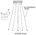
図3は3D造影スキャンの途中にBモードスキャンを実行するためのスキャンシーケンスの第1の例を示す図である。 FIG. 3 is a diagram showing a first example of a scan sequence for executing a B-mode scan in the middle of a 3D contrast scan.
図3において紙面に平行な円弧方向は超音波プローブ3のエレベーション方向を示している。また、図3において実線は3D造影スキャンにおける走査面の位置を示し、点線はBモードスキャンにおける走査面の位置を示す。但し、説明簡易化のため、実際には重なる実線と点線とを重ねずに表示している。 In FIG. 3, the arc direction parallel to the paper surface indicates the elevation direction of the ultrasonic probe 3. In FIG. 3, the solid line indicates the position of the scanning plane in the 3D contrast scan, and the dotted line indicates the position of the scanning plane in the B-mode scan. However, in order to simplify the explanation, the overlapping solid lines and the dotted lines are actually displayed without overlapping.
図3に示すように、エレベーション方向における複数の走査面から超音波造影ボリューム画像データ用の超音波反射エコー信号が順次収集されるようにスキャンシーケンスを決定することができる。更に、3D造影スキャンの対象となる3D領域をエレベーション方向に2等分する2D領域、つまり3D領域の中心位置におけるA面から超音波形態画像データ用の超音波反射エコー信号が収集されるように、スキャンシーケンスを決定することができる。 As shown in FIG. 3, the scan sequence can be determined so that ultrasound reflected echo signals for ultrasound contrast volume image data are sequentially collected from a plurality of scan planes in the elevation direction. Furthermore, an ultrasound reflected echo signal for ultrasound morphological image data is collected from the 2D area that bisects the 3D area to be subjected to the 3D contrast scan in the elevation direction, that is, the A plane at the center position of the 3D area. In addition, the scan sequence can be determined.
従って、3D造影スキャンの対象となる走査面の数が奇数であれば、Bモードスキャン用の走査面は、3D造影スキャンの対象となる中心の走査面と重なる。また、時間的にも、Bモードスキャンは、3D造影スキャンの中心時刻において実行される。これにより、3D造影スキャンによって収集される超音波造影ボリューム画像データ用の超音波反射エコー信号と、Bモードスキャンによって収集される超音波形態画像データ用の超音波反射エコー信号との間における時相差を最小限にすることができる。 Therefore, if the number of scan planes to be subjected to 3D contrast scan is an odd number, the scan plane for B-mode scan overlaps the central scan plane to be subject to 3D contrast scan. In terms of time, the B-mode scan is executed at the center time of the 3D contrast scan. Thereby, the time phase difference between the ultrasound reflected echo signal for the ultrasound contrast volume image data collected by the 3D contrast scan and the ultrasound reflected echo signal for the ultrasound morphological image data collected by the B-mode scan. Can be minimized.
また、Bモードスキャンを2Dスキャンとすることによって、超音波造影ボリューム画像データの時間分解能及びリアルタイム性を向上させることができる。 Moreover, the time resolution and real-time property of ultrasonic contrast volume image data can be improved by making the B-mode scan a 2D scan.
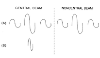
図4は図3に示す3D造影スキャン及びBモードスキャンにおいてそれぞれ送信される送信信号の波形の一例を示す模式図である。 FIG. 4 is a schematic diagram showing an example of a waveform of a transmission signal transmitted in each of the 3D contrast scan and the B-mode scan shown in FIG.
図4(A)は3D造影スキャンにおいて送信される送信信号の波形の一例を示し、図4(B)はBモードスキャンにおいて送信される送信信号の波形の一例を示す。図4(A)に示すように、例えば、振幅を変調して低周波の送信信号を3回送信する3レート振幅変調(AM: Amplitude Modulation)法によって、中心の走査面及び中心以外の走査面を含む全走査面の3D造影スキャンを実行することができる。一方、図4(B)に示すように、Bモードスキャンは、中心の走査面のみを対象として、振幅及び周波数が変調されない基本波帯域の送信信号を1回送信する1レート基本波モードで実行することができる。 FIG. 4A shows an example of a waveform of a transmission signal transmitted in a 3D contrast scan, and FIG. 4B shows an example of a waveform of a transmission signal transmitted in a B mode scan. As shown in FIG. 4A, for example, a center scanning plane and a scanning plane other than the center are modulated by a three-rate amplitude modulation (AM) method that modulates the amplitude and transmits a low-frequency transmission signal three times. 3D contrast scans of all scan planes including can be performed. On the other hand, as shown in FIG. 4 (B), the B-mode scan is executed in the 1-rate fundamental wave mode in which the transmission signal in the fundamental band whose amplitude and frequency are not modulated is transmitted once only for the central scanning plane. can do.
このように走査面単位で、3D造影スキャンとBモードスキャンとを交互に実行する交互スキャン用のスキャンシーケンスをスキャン制御部10において設定し、設定したスキャンシーケンスに従って3D造影スキャンの途中にBモードスキャンを実行することができる。
In this way, the
尚、造影スキャンの手法としては、AM法の他、位相を変調するPM法、振幅及び位相の双方を変調する振幅位相変調(AMPM)法が知られている。このように、造影スキャンの手法及び送信レート等の条件は、任意に選択することができる。 In addition to the AM method, a PM method for modulating the phase and an amplitude phase modulation (AMPM) method for modulating both the amplitude and the phase are known as contrast scan methods. As described above, conditions such as a contrast scan method and a transmission rate can be arbitrarily selected.
図5は3D造影スキャンの途中にBモードスキャンを実行するためのスキャンシーケンスの第2の例を示す図である。 FIG. 5 is a diagram showing a second example of a scan sequence for executing a B-mode scan in the middle of a 3D contrast scan.
図5において紙面に平行な円弧方向は超音波プローブ3のアジマス方向を示している。また、図5において実線は3D造影スキャンにおける送信ビームの位置を示し、点線はBモードスキャンにおける送信ビームの位置を示す。但し、説明簡易化のため、実際には重なる実線と点線とを重ねずに表示している。 In FIG. 5, the arc direction parallel to the paper surface indicates the azimuth direction of the ultrasonic probe 3. In FIG. 5, the solid line indicates the position of the transmission beam in the 3D contrast scan, and the dotted line indicates the position of the transmission beam in the B-mode scan. However, in order to simplify the explanation, the overlapping solid lines and the dotted lines are actually displayed without overlapping.
図5に示すように、アジマス方向における複数のB面から超音波造影ボリューム画像データ用の超音波反射エコー信号が順次収集されるようにスキャンシーケンスを決定することができる。更に、3D造影スキャンの対象となる3D領域をアジマス方向に2等分する2D領域、つまり3D領域の中心位置におけるB面から超音波形態画像データ用の超音波反射エコー信号が収集されるように、スキャンシーケンスを決定することができる。 As shown in FIG. 5, the scan sequence can be determined so that ultrasound reflected echo signals for ultrasound contrast volume image data are sequentially collected from a plurality of B surfaces in the azimuth direction. Furthermore, an ultrasonic reflection echo signal for ultrasonic morphological image data is collected from a 2D area that bisects the 3D area to be subjected to the 3D contrast scan in the azimuth direction, that is, the B surface at the center position of the 3D area. The scan sequence can be determined.
この場合、3D造影スキャンにより、各走査面においてアジマス方向に異なる複数の走査位置に向かって複数の送信ビームが送信される。一方、Bモードスキャンにより、各走査面においてアジマス方向の中心位置のみに送信ビームが送信される。 In this case, a plurality of transmission beams are transmitted by a 3D contrast scan toward a plurality of scanning positions different in the azimuth direction on each scanning plane. On the other hand, the transmission beam is transmitted only to the center position in the azimuth direction on each scanning plane by the B mode scan.
従って、3D造影スキャンの対象となるB面の数が奇数であれば、Bモードスキャン用のB面は、3D造影スキャンの対象となる中心のB面と重なる。また、時間的には、3D造影スキャン用の送信ビームが順次送信される場合には、各走査面上において、Bモードスキャン用の送信ビームが、3D造影スキャン用の送信ビームの送信期間における中心時刻において送信される。これにより、3D造影スキャンによって収集される超音波造影ボリューム画像データ用の超音波反射エコー信号と、Bモードスキャンによって収集される超音波形態画像データ用の超音波反射エコー信号との間における時相差を最小限にすることができる。 Therefore, if the number of B surfaces to be subjected to 3D contrast scanning is an odd number, the B surface for B mode scanning overlaps with the central B surface to be subjected to 3D contrast scanning. In addition, in terms of time, when transmission beams for 3D contrast scanning are sequentially transmitted, the transmission beam for B-mode scanning is centered in the transmission period of the transmission beam for 3D contrast scanning on each scanning plane. Sent at time. Thereby, the time phase difference between the ultrasound reflected echo signal for the ultrasound contrast volume image data collected by the 3D contrast scan and the ultrasound reflected echo signal for the ultrasound morphological image data collected by the B-mode scan. Can be minimized.
また、Bモードスキャンを2D領域から超音波反射エコー信号を収集するスキャンとすることによって、超音波造影ボリューム画像データの時間分解能及びリアルタイム性を向上させることができる。 Moreover, the time resolution and real-time property of the ultrasonic contrast volume image data can be improved by using the B-mode scan as a scan for collecting ultrasonic reflection echo signals from the 2D region.
図6は図5に示す3D造影スキャン及びBモードスキャンにおいてそれぞれ送信される送信信号の波形の一例を示す模式図である。 FIG. 6 is a schematic diagram showing an example of a waveform of a transmission signal transmitted in each of the 3D contrast scan and the B-mode scan shown in FIG.
図6(A)は3D造影スキャンにおいて送信される送信信号の波形の一例を示し、図6(B)はBモードスキャンにおいて送信される送信信号の波形の一例を示す。図6(A)に示すように、例えば、3レートAM法によりアジマス方向の対象範囲全域に亘って超音波送信ビームを送信することによって3D造影スキャンを実行することができる。一方、図6(B)に示すように、Bモードスキャンは、振幅及び周波数が変調されない基本帯域の送信信号で構成される超音波送信ビームをアジマス方向の中心位置に対してのみ1回送信する1レート基本波モードで実行することができる。 FIG. 6A shows an example of a waveform of a transmission signal transmitted in a 3D contrast scan, and FIG. 6B shows an example of a waveform of a transmission signal transmitted in a B mode scan. As shown in FIG. 6A, for example, a 3D contrast scan can be executed by transmitting an ultrasonic transmission beam over the entire target range in the azimuth direction by the 3-rate AM method. On the other hand, as shown in FIG. 6B, in the B-mode scan, an ultrasonic transmission beam composed of a transmission signal in a basic band whose amplitude and frequency are not modulated is transmitted only once to the center position in the azimuth direction. It can be executed in the 1 rate fundamental wave mode.
このように送信ビーム単位で、3D造影スキャンとBモードスキャンとを交互に実行する交互スキャン用のスキャンシーケンスをスキャン制御部10において設定し、設定したスキャンシーケンスに従って3D造影スキャンの途中にBモードスキャンを実行することができる。
As described above, the
もちろん、A面及びB面の双方から直交する2断面における超音波形態画像データ用の超音波反射エコー信号が収集されるようにスキャンシーケンスを設定することもできる。その場合には、図3に例示されるスキャンシーケンスと、図5に例示されるスキャンシーケンスとを組合せればよい。また、A面又はB面と平行でない単一又は複数の面から超音波形態画像データ用の超音波反射エコー信号が収集されるようにスキャンシーケンスを設定することもできる。 Of course, the scan sequence can also be set so that ultrasonic reflected echo signals for ultrasonic morphological image data in two cross sections orthogonal to both the A plane and the B plane are collected. In that case, the scan sequence illustrated in FIG. 3 and the scan sequence illustrated in FIG. 5 may be combined. In addition, the scan sequence can be set so that ultrasonic reflected echo signals for ultrasonic image data are collected from a single surface or a plurality of surfaces that are not parallel to the A surface or the B surface.
すなわち、3D領域から超音波造影ボリューム画像データ用の超音波反射エコー信号を収集する3D造影スキャンを実行する一方、エレベーション方向における特定の走査面及びアジマス方向における特定の走査位置から超音波形態画像データ用の超音波反射エコー信号を収集するBモードスキャンを実行するスキャンシーケンスを設定することができる。 That is, while performing a 3D contrast scan to collect ultrasound reflected echo signals for ultrasound contrast volume image data from the 3D region, an ultrasonic form image from a specific scan plane in the elevation direction and a specific scan position in the azimuth direction A scan sequence for executing a B-mode scan for collecting ultrasonic reflected echo signals for data can be set.
図7は、3D造影スキャンの途中にBモードスキャンを実行するためのスキャンシーケンスの第3の例を示す図である。 FIG. 7 is a diagram illustrating a third example of a scan sequence for executing a B-mode scan in the middle of a 3D contrast scan.
図7において紙面に平行な円弧方向は超音波プローブ3のエレベーション方向を示している。また、図7において点線は、Bモードスキャンにおける走査面の位置を示し、実線で囲まれた領域はBモードスキャンを複数回繰返すことによって時間的に分割される3D造影スキャンの対象となる複数の3D領域を示す。 In FIG. 7, the arc direction parallel to the paper surface indicates the elevation direction of the ultrasonic probe 3. In FIG. 7, the dotted line indicates the position of the scanning surface in the B-mode scan, and the region surrounded by the solid line is a plurality of 3D contrast scan targets that are temporally divided by repeating the B-mode scan a plurality of times. 3D region is shown.
図7に示すように、エレベーション方向における複数の走査面から超音波造影ボリューム画像データ用の超音波反射エコー信号が順次収集されるようにスキャンシーケンスを決定することができる。更に、3D造影スキャンの対象となる3D領域をエレベーション方向に2分割する2D領域から超音波形態画像データ用の超音波反射エコー信号が3D造影スキャン中において複数回収集されるように、スキャンシーケンスを決定することができる。図7に示す例では、3D造影スキャンの対象となる3D造影ボリューム領域が、3D造影ボリューム領域の中心位置に対する2回のBモードスキャンによってエレベーション方向に空間的に3等分されている。 As shown in FIG. 7, the scan sequence can be determined so that ultrasound reflected echo signals for ultrasound contrast volume image data are sequentially collected from a plurality of scan planes in the elevation direction. In addition, the scan sequence so that the ultrasound reflected echo signal for ultrasound morphological image data is collected multiple times during the 3D contrast scan from the 2D area that divides the 3D area subject to 3D contrast scan into two in the elevation direction. Can be determined. In the example shown in FIG. 7, the 3D contrast volume area to be subjected to the 3D contrast scan is spatially divided into three equal parts in the elevation direction by two B-mode scans with respect to the center position of the 3D contrast volume area.
つまり、超音波形態画像データ用の超音波反射エコー信号が3D造影スキャン中において複数回収集されるようにスキャンシーケンスを決定することもできる。3D造影スキャン中において複数回超音波形態画像データ用の超音波反射エコー信号を収集するようにすれば、超音波形態画像のフレームレートを向上させることができる。 That is, the scan sequence can be determined so that the ultrasonic reflection echo signal for the ultrasonic morphological image data is acquired a plurality of times during the 3D contrast scan. If the ultrasonic echo signals for ultrasonic morphological image data are collected a plurality of times during the 3D contrast scan, the frame rate of the ultrasonic morphological image can be improved.
図8は、図7に示す3D造影スキャンによって取得される超音波造影ボリューム画像データ及びBモードスキャンによって取得される超音波形態画像データの各更新レートを示す図である。 FIG. 8 is a diagram showing update rates of the ultrasound contrast volume image data acquired by the 3D contrast scan shown in FIG. 7 and the ultrasound morphological image data acquired by the B-mode scan.
図8において横軸は時間を示し、縦軸方向は走査面に平行な方向を示す。図7に示す3D造影スキャンの対象となるセグメント化された複数の3D領域に対する走査タイミング及び3D造影ボリュームの中心位置に対するBモードスキャンの走査タイミングを時間方向に表示させると図8のようになる。すなわち、3D造影スキャン中においてBモードスキャンを複数回実行すると、超音波形態画像データの更新レートが超音波造影ボリューム画像データの更新レートよりも高くなる。 In FIG. 8, the horizontal axis indicates time, and the vertical axis direction indicates a direction parallel to the scanning plane. When the scanning timing for a plurality of segmented 3D regions to be subjected to the 3D contrast scan shown in FIG. 7 and the scanning timing of the B-mode scan for the center position of the 3D contrast volume are displayed in the time direction, FIG. 8 is obtained. That is, when the B-mode scan is executed a plurality of times during the 3D contrast scan, the update rate of the ultrasound morphological image data becomes higher than the update rate of the ultrasound contrast volume image data.
具体的には、3D造影ボリュームの中心位置における2D領域から超音波形態画像データ用の超音波反射エコー信号が3D造影スキャン中においてN回収集されるように、3D造影スキャンの対象となるボリューム領域を時間的かつ空間的に(N+1)分割すると、超音波形態画像データのフレームレートは、超音波造影ボリューム画像データの更新レートのN倍となる。 Specifically, the volume region that is the target of the 3D contrast scan so that the ultrasound reflected echo signals for ultrasound morphological image data are collected N times during the 3D contrast scan from the 2D region at the center position of the 3D contrast volume Is temporally and spatially divided (N + 1), the frame rate of the ultrasonic morphological image data is N times the update rate of the ultrasonic contrast volume image data.
図7及び図8に示す例では、3D造影スキャンの対象となるボリューム領域が2回のBモードスキャンによって時間的かつ空間的に3分割されている。この場合、超音波形態画像データのフレームレートが、超音波造影ボリューム画像データの更新レートの2倍となる。すなわち、超音波造影ボリューム画像データが1回更新される間において、超音波形態画像データが2回更新される。 In the example shown in FIGS. 7 and 8, the volume region to be subjected to the 3D contrast scan is divided into three temporally and spatially by two B-mode scans. In this case, the frame rate of the ultrasonic morphological image data is twice the update rate of the ultrasonic contrast volume image data. That is, while the ultrasound contrast volume image data is updated once, the ultrasound form image data is updated twice.
このように、走査位置のオリエンテーションを効果的に行えるように、超音波形態画像データのフレームレートを、超音波造影ボリューム画像データの更新レートよりも高いレートに設定することができる。その場合、3D造影スキャンの対象となるボリューム領域を空間的かつ時間的に等間隔に分割するタイミングでBモードスキャンを複数回繰返すことによって、超音波造影ボリューム画像データと超音波形態画像データとの間における時相差を最小限にすることができる。 As described above, the frame rate of the ultrasonic morphological image data can be set to a higher rate than the update rate of the ultrasonic contrast volume image data so that the orientation of the scanning position can be effectively performed. In that case, the B-mode scan is repeated a plurality of times at the timing at which the volume region to be subjected to the 3D contrast scan is spatially and temporally divided into equal intervals, so that the ultrasound contrast volume image data and the ultrasound morphological image data are The time difference between them can be minimized.
従って、Bモードスキャンの実行条件を、図8に例示されるように超音波造影ボリューム画像データに対する超音波形態画像データの更新レート比として設定することもできる。具体的には、超音波造影ボリューム画像データに対する超音波形態画像データの更新レート比、すなわち超音波形態画像データのフレームレートを超音波造影ボリューム画像データの更新レートで除算した値がNであれば、3D造影スキャンの対象となるボリューム領域を時間的かつエレベーション方向に空間的に(N+1)等分するタイミングでN回Bモードスキャンが繰返されるスキャン条件を設定することができる。 Therefore, the execution condition of the B-mode scan can be set as the update rate ratio of the ultrasonic morphological image data to the ultrasonic contrast volume image data as illustrated in FIG. Specifically, if the update rate ratio of the ultrasound morphological image data to the ultrasound contrast volume image data, that is, the value obtained by dividing the frame rate of the ultrasound morphological image data by the update rate of the ultrasound contrast volume image data is N. In addition, it is possible to set a scan condition in which the B-mode scan is repeated N times at a timing at which the volume region to be subjected to the 3D contrast scan is temporally and spatially (N + 1) equally divided in the elevation direction.
この場合、N=1に設定すれば、超音波形態画像データのフレームレートが超音波造影ボリューム画像データの更新レートと一致する。従って、図3に例示される交互スキャンの条件が設定されることになる。すなわち、3D造影スキャンの対象となるボリューム領域内に設定された単一の領域から超音波形態画像データ用の超音波反射エコー信号を収集するスキャンシーケンスが設定される。 In this case, if N = 1 is set, the frame rate of the ultrasound morphological image data matches the update rate of the ultrasound contrast volume image data. Therefore, the conditions for the alternate scan illustrated in FIG. 3 are set. That is, a scan sequence for collecting ultrasonic reflection echo signals for ultrasonic morphological image data from a single region set in a volume region to be subjected to 3D contrast scanning is set.
このように、スキャン制御部10では、Bモードスキャンの対象となる走査面、Bモードスキャンの対象となる走査位置又は超音波形態画像データのフレームレートとして超音波形態画像データ用の超音波反射エコー信号の受信条件を設定することができる。すなわち、3D造影スキャンとBモードスキャンとを走査面を単位として交互に実行するスキャンシーケンス、3D造影スキャンとBモードスキャンとを送信ビームを単位として交互に実行するスキャンシーケンス又は3D造影スキャンとBモードスキャンとを更新レートに従って交互に実行するスキャンシーケンスをスキャン制御部10において設定することができる。
As described above, the
そのために、スキャン制御部10は表示装置7にスキャン条件の設定画面を表示させる機能を有している。そして、スキャン条件の設定画面を参照した入力装置8の操作によってスキャン条件を設定することができる。すなわち、スキャン制御部10はスキャン条件を設定するためのユーザインタフェース(U/I: user interface)としての機能を有している。
For this purpose, the
スキャン条件の設定画面では、Bモードスキャンの対象領域をエレベーション方向に垂直な2D領域のみ、アジマス方向に垂直な2D領域のみ又はエレベーション方向に垂直な2D領域とアジマス方向に垂直な2D領域の双方のいずれにするかといった条件や、超音波造影ボリューム画像データに対する超音波形態画像データの更新レート比を設定できるようにすることができる。 On the scan condition setting screen, the target area for B-mode scanning is only 2D areas perpendicular to the elevation direction, only 2D areas perpendicular to the azimuth direction, or 2D areas perpendicular to the elevation direction and 2D areas perpendicular to the azimuth direction. It is possible to set a condition such as either of them or an update rate ratio of the ultrasonic morphological image data to the ultrasonic contrast volume image data.
また、スキャン制御部10では、入力装置8から入力される指示情報に従って超音波形態画像データのフレームレートを調整できるようにすることができる。すなわち、ボリューム領域に対する1回の3D造影スキャン中における超音波形態画像データ用の超音波反射エコー信号の受信回数をマニュアルで調整することができる。この場合、超音波造影ボリューム画像データに対する超音波形態画像データの更新レート比を入力装置8の操作によってマニュアル調整できるようにしてもよい。
Further, the
スキャン制御部10では、このような3D造影スキャンの対象となるボリューム領域及びBモードスキャンの対象領域の他、超音波プローブ3に印加される送信信号の周波数帯域も設定される。送信信号の周波数帯域は、造影剤で反射する超音波反射信号の感度が良好となり、かつ超音波形態画像が高画質で得られるように、広帯域に設定することができる。但し、送信信号の周波数帯域を、3D造影スキャンによって収集された受信信号の一部を超音波形態ボリューム画像データの生成に用いるか否かに応じてより適切な帯域に設定することがエネルギの有効利用に繋がる。
In the
図9は、3D造影スキャンによって収集される受信信号を超音波造影ボリューム画像データの生成のみに用いる場合に適切な送信信号の周波数特性を示す図である。 FIG. 9 is a diagram showing frequency characteristics of a transmission signal suitable when the reception signal collected by the 3D contrast scan is used only for generating the ultrasound contrast volume image data.
図9において横軸は周波数fを示し、縦軸は送信信号の振幅A [dB]を示す。3D造影スキャン及びBモードスキャン用の各送信信号の周波数帯域は、図9の一点鎖線で示すような超音波プローブ3に印加することが可能な送信信号の周波数帯域の範囲内でそれぞれ個別に設定することができる。 In FIG. 9, the horizontal axis represents the frequency f, and the vertical axis represents the amplitude A [dB] of the transmission signal. The frequency band of each transmission signal for 3D contrast scan and B-mode scan is individually set within the range of the frequency band of the transmission signal that can be applied to the ultrasonic probe 3 as shown by the one-dot chain line in FIG. can do.
3D造影スキャン用の送信信号の周波数帯域は、図9の実線で示すように、超音波造影剤で反射する超音波反射信号の感度が良好となる低周波領域に設定することができる。一方、モニタ用の超音波形態画像データを収集するためのBモードスキャン用の送信信号の周波数帯域は、画質が良好となるように図9の点線で示すように、超音波プローブ3に印加することが可能な送信信号の周波数帯域の中心付近における広帯域に設定することができる。 As shown by the solid line in FIG. 9, the frequency band of the transmission signal for 3D contrast scan can be set in a low frequency region where the sensitivity of the ultrasound reflected signal reflected by the ultrasound contrast agent is good. On the other hand, the frequency band of the transmission signal for B-mode scan for collecting the ultrasonic morphological image data for monitoring is applied to the ultrasonic probe 3 as indicated by the dotted line in FIG. 9 so that the image quality is good. The transmission signal can be set to a wide band near the center of the frequency band of the transmission signal.
つまり、3D造影スキャンによって収集される受信信号を超音波造影ボリューム画像データの生成のみに用いる場合には、3D造影スキャンにおいて超音波造影画像データの生成に適した周波数特性を有する超音波を超音波プローブ3から送信させる一方、Bモードスキャンにおいて超音波形態画像データの生成に適した周波数特性を有する超音波を超音波プローブ3から送信させることができる。このように、送信信号の周波数特性をスキャンごとに適切な特性に設定することにより、送信信号を生成するためのエネルギ効率を向上させることができる。 In other words, when the received signal collected by the 3D contrast scan is used only for the generation of the ultrasound contrast volume image data, the ultrasound having frequency characteristics suitable for the generation of the ultrasound contrast image data in the 3D contrast scan is converted into the ultrasound. While transmitting from the probe 3, ultrasonic waves having frequency characteristics suitable for generating ultrasonic morphological image data in the B-mode scan can be transmitted from the ultrasonic probe 3. Thus, by setting the frequency characteristic of the transmission signal to an appropriate characteristic for each scan, the energy efficiency for generating the transmission signal can be improved.
一方、3D造影スキャンによって収集される受信信号を超音波造影ボリューム画像データ及び超音波形態ボリューム画像データの双方の生成に用いる場合には、3D造影スキャンにおいて超音波形態ボリュームデータ及び超音波造影画像データの双方の生成に適した周波数特性を有する超音波を超音波プローブ3から送信させることが効果的である。 On the other hand, when the received signals collected by the 3D contrast scan are used to generate both the ultrasound contrast volume image data and the ultrasound shape volume image data, the ultrasound shape volume data and the ultrasound contrast image data in the 3D contrast scan It is effective to transmit an ultrasonic wave having frequency characteristics suitable for generation of both from the ultrasonic probe 3.
図10は、3D造影スキャンによって収集される受信信号の一部を超音波形態ボリューム画像データの生成に用いる場合に適切な送信信号の周波数特性を示す図である。 FIG. 10 is a diagram illustrating frequency characteristics of a transmission signal suitable for a case where a part of the reception signal collected by the 3D contrast scan is used for generation of ultrasonic form volume image data.
図10において横軸は周波数fを示し、縦軸は送信信号の振幅A [dB]を示す。図9に示す例と同様に、3D造影スキャン及びBモードスキャン用の各送信信号の周波数帯域は、図10の一点鎖線で示すような超音波プローブ3に印加することが可能な送信信号の周波数帯域の範囲内でそれぞれ個別に設定することができる。 In FIG. 10, the horizontal axis represents the frequency f, and the vertical axis represents the amplitude A [dB] of the transmission signal. As in the example shown in FIG. 9, the frequency band of each transmission signal for 3D contrast scanning and B-mode scanning is the frequency of the transmission signal that can be applied to the ultrasonic probe 3 as shown by the one-dot chain line in FIG. Each can be set individually within the bandwidth.
Bモードスキャン用の送信信号の周波数帯域は、図9に示す例と同様に、画質が良好となるように図10の点線で示すように超音波プローブ3に印加することが可能な送信信号の周波数帯域の中心付近における広帯域に設定することができる。 As in the example shown in FIG. 9, the frequency band of the transmission signal for B-mode scanning is the transmission signal that can be applied to the ultrasonic probe 3 as indicated by the dotted line in FIG. A wide band near the center of the frequency band can be set.
一方、3D造影スキャン用の送信信号の周波数帯域は、図10の実線で示すように、造影剤で反射する超音波反射信号の感度が良好となる低周波領域を含み、かつ組織の超音波形態画像が高画質で得られるように超音波プローブ3に印加することが可能な送信信号の周波数帯域の中心付近も含む、より広い帯域に設定することができる。つまり、3D造影スキャン用の送信信号は、造影剤と組織の双方の画像化に好適な広帯域信号とすることができる。 On the other hand, the frequency band of the transmission signal for the 3D contrast scan includes a low frequency region where the sensitivity of the ultrasound reflected signal reflected by the contrast agent is good as shown by the solid line in FIG. It is possible to set a wider band including the vicinity of the center of the frequency band of the transmission signal that can be applied to the ultrasonic probe 3 so that an image can be obtained with high image quality. That is, the transmission signal for 3D contrast scan can be a broadband signal suitable for imaging both the contrast agent and the tissue.
スキャン制御部10において設定されるその他のスキャン条件としては、並列同時受信法によりスキャンを実行するための条件が挙げられる。並列同時受信法は、超音波プローブ3に備えられる複数の超音波振動子を複数の超音波振動子群に分割し、超音波振動子群ごとに独立して制御することによって異なるラスタ方向から同時に超音波エコー信号を受信する技術である。並列同時受信法によりスキャンを実行する場合には、超音波の送信パターンとして平面波又は拡散波が被検体Pに向けて送信される。
Other scan conditions set in the
複数の超音波振動子を用いて互いに異なる方向から同時に超音波を受信する並列同時受信によって3D造影スキャン及びBモードスキャンの少なくとも一方が実行されるようにスキャン条件を設定すれば、超音波造影ボリューム画像データの時間分解能及びリアルタイム性を一層向上させ、かつ超音波形態画像データと超音波造影ボリューム画像データとの間における時相差も低減させることができる。 If the scan condition is set so that at least one of the 3D contrast scan and the B-mode scan is executed by parallel simultaneous reception in which ultrasonic waves are simultaneously received from different directions using a plurality of ultrasonic transducers, an ultrasound contrast volume The temporal resolution and real-time property of the image data can be further improved, and the time difference between the ultrasonic morphological image data and the ultrasonic contrast volume image data can be reduced.
特に、同一の走査面上の走査位置からであれば超音波形態画像データ用の超音波反射信号と超音波造影ボリューム画像データ用の超音波反射信号をほぼ同時に受信することも可能となる。つまり、並列同時受信法によって、3D造影スキャンによる超音波信号の送受信中にBモードスキャンによる超音波信号の送受信を行うことも可能となる。 In particular, from the scanning position on the same scanning plane, it is also possible to receive the ultrasonic reflection signal for ultrasonic morphological image data and the ultrasonic reflection signal for ultrasonic contrast volume image data almost simultaneously. That is, by the parallel simultaneous reception method, it is also possible to transmit / receive ultrasonic signals by B-mode scanning while transmitting / receiving ultrasonic signals by 3D contrast scanning.
次に、データ処理系5の機能について説明する。 Next, functions of the data processing system 5 will be described.
データ処理系5は、第1のスキャンとして実行される3D造影スキャンによってボリュームデータとして取得される第1の受信信号に基づいて超音波造影ボリューム画像データを生成する一方、第2のスキャンとして実行されるBモードスキャンよって取得される第2の受信信号に基づいてモニタ用の超音波形態画像データを生成する機能を有している。加えて、データ処理系5では、超音波造影ボリューム画像データの生成用に取得される第1の受信信号の一部に基づいて被検体Pの形態が描出された超音波形態ボリュームデータを生成することができるように構成されている。 The data processing system 5 generates ultrasonic contrast volume image data based on the first received signal acquired as volume data by the 3D contrast scan executed as the first scan, while being executed as the second scan. A function of generating ultrasonic morphological image data for monitoring based on the second received signal acquired by the B-mode scan. In addition, the data processing system 5 generates ultrasonic form volume data in which the form of the subject P is depicted based on a part of the first reception signal acquired for generating ultrasonic contrast volume image data. It is configured to be able to.
データ処理系5のドプラ処理部12は、3D造影スキャンによってボリューム領域から超音波ドプラ信号として収集された第1の受信信号を送受信ユニット9から取得して、周波数解析を含むドプラ処理を実行することにより、血流の速度、分散、パワー等の動態情報をカラー等によって表示する超音波造影ボリューム画像データを生成する機能を有する。
The
尚、超音波造影ボリューム画像データに2D化する表示処理を施して表示させると、3D造影スキャンの対象となるボリューム領域の分割位置に対応する位置に不連続な線が描出される可能性がある。そこで、表示される造影画像の不連続性を低減するために、ドプラ処理部12において超音波造影ボリューム画像データにスムージングフィルタを適用するようにしてもよい。その場合、ボリューム領域の分割位置は、スキャン条件として設定される既知の情報であるから、ボリューム領域の分割位置に対応する位置に対してのみ局所的にスムージングフィルタをかけることが好適である。
In addition, when the 2D display processing is performed on the ultrasound contrast volume image data and displayed, a discontinuous line may be drawn at a position corresponding to the division position of the volume area to be subjected to the 3D contrast scan. . Therefore, in order to reduce the discontinuity of the displayed contrast image, the
Bモード処理部11は、Bモードスキャンよって収集された第2の受信信号を送受信ユニット9から取得して、対数変換処理及び包絡線検波処理を含むBモード画像データの生成処理を実行することにより、第2の受信信号の強度が輝度で表示されるBモード画像データとして超音波形態画像データを生成する機能を有する。 The B-mode processing unit 11 acquires the second received signal collected by the B-mode scan from the transmission / reception unit 9 and executes a B-mode image data generation process including a logarithmic conversion process and an envelope detection process. , And a function of generating ultrasonic morphological image data as B-mode image data in which the intensity of the second received signal is displayed in luminance.
また、Bモード処理部11は、3D造影スキャンによってボリューム領域から収集された第1の受信信号を送受信ユニット9から取得して、造影剤の分布をグレースケールで表示させるための超音波造影ボリューム画像データを生成する機能を有する。この場合においても、3D造影スキャンの対象となるボリューム領域の分割位置における不連続性を低減するために、スムージングフィルタを適用することができる。 In addition, the B-mode processing unit 11 acquires the first reception signal collected from the volume region by the 3D contrast scan from the transmission / reception unit 9 and displays the contrast agent distribution in gray scale. It has a function to generate data. Even in this case, a smoothing filter can be applied in order to reduce discontinuity at the division position of the volume region to be subjected to the 3D contrast scan.
更に、Bモード処理部11は、3D造影スキャンによって収集された第1の受信信号の一部に基づいて、超音波形態ボリュームデータを生成する機能を有している。 Further, the B-mode processing unit 11 has a function of generating ultrasonic volume data based on a part of the first reception signal collected by the 3D contrast scan.
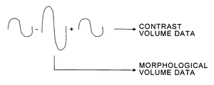
3D造影スキャンによって収集される受信信号には、造影剤に反射して生じた非線形成分と、組織に反射して生じた線形成分が含まれる。従って、図4及び図6に例示されるような3レートAM法やその他の変調法によって変調された複数の超音波を順次送信して得られる複数の受信信号間で線形演算を行えば、組織に反射して生じた線形成分を除去して造影剤に反射して生じた非線形成分を抽出することができる。そして、抽出された非線形成分を用いて超音波造影ボリューム画像データを生成することが可能となる。 The received signal collected by the 3D contrast scan includes a non-linear component generated by reflection on the contrast agent and a linear component generated by reflection on the tissue. Therefore, if linear calculation is performed between a plurality of received signals obtained by sequentially transmitting a plurality of ultrasonic waves modulated by the three-rate AM method and other modulation methods as illustrated in FIGS. It is possible to extract the non-linear component generated by reflecting the contrast medium and removing the linear component generated by the reflection. Then, it is possible to generate ultrasonic contrast volume image data using the extracted nonlinear component.
但し、3D造影スキャンによって収集される線形演算前の受信信号には、組織に反射して生じた線形成分が含まれている。そこで、3D造影スキャンによって3Dボリューム領域から収集された線形演算前の受信信号に含まれる線形成分を用いれば、超音波形態ボリューム画像データを生成することができる。 However, the received signal before linear calculation collected by the 3D contrast scan includes a linear component generated by reflection on the tissue. Therefore, ultrasonic volume image data can be generated by using a linear component included in a reception signal before linear calculation collected from a 3D volume region by a 3D contrast scan.
図11は3レートAM法による3D造影スキャンによって超音波造影ボリューム画像データ及び超音波形態ボリュームデータを生成する方法を説明する図である。 FIG. 11 is a diagram for explaining a method of generating ultrasound contrast volume image data and ultrasound shape volume data by 3D contrast scan using the 3-rate AM method.
単純な3レートAM法の場合には、3D造影スキャンにおいて図11に示すように振幅が2倍に変調された超音波と振幅が変調されていない2つの超音波が順次送信される。従って、振幅が変調されていない2つの超音波の送信によって収集された2つの受信信号から振幅が2倍に変調された超音波の送信によって収集された受信信号を減算する線形演算によって組織からの線形成分をキャンセルし、造影剤からの非線形成分を抽出することができる。そして、抽出した非線形成分のドプラ解析を含むデータ処理によって血流の速度、パワー、分散等の血流動態情報を表す超音波造影ボリューム画像データを生成することができる。或いは、簡易な処理によって造影剤の分布をグレースケールで表す超音波造影ボリューム画像データを生成することもできる。 In the case of a simple three-rate AM method, as shown in FIG. 11, in the 3D contrast scan, an ultrasonic wave whose amplitude is doubled and two ultrasonic waves whose amplitude is not modulated are sequentially transmitted. Therefore, from the tissue by a linear operation that subtracts the received signal collected by the transmission of the ultrasonic wave whose amplitude is doubled from the two received signals collected by the transmission of the two ultrasonic waves whose amplitude is not modulated. It is possible to cancel the linear component and extract the nonlinear component from the contrast agent. Then, ultrasonic contrast volume image data representing blood flow dynamic information such as blood flow velocity, power, and dispersion can be generated by data processing including Doppler analysis of the extracted nonlinear component. Alternatively, it is also possible to generate ultrasonic contrast volume image data that represents the distribution of contrast medium in gray scale by a simple process.
一方、線形演算前における3つの受信信号には、それぞれ線形成分と非線形成分が含まれている。そこで、周波数方向のフィルタ処理等によって1つの受信信号から線形成分を抽出することができる。受信信号は3D造影スキャンに3Dボリューム領域から収集されるため、3D領域から収集された受信信号の線形成分に基づいて超音波形態ボリューム画像データを生成することができる。 On the other hand, the three received signals before the linear calculation each include a linear component and a nonlinear component. Therefore, a linear component can be extracted from one received signal by frequency-direction filtering or the like. Since the received signal is collected from the 3D volume region in the 3D contrast scan, the ultrasonic form volume image data can be generated based on the linear component of the received signal collected from the 3D region.
図12はPM法による3D造影スキャンによって超音波造影ボリューム画像データ及び超音波形態ボリューム画像データを生成する方法を説明する図である。 FIG. 12 is a diagram for explaining a method of generating ultrasound contrast volume image data and ultrasound morphology volume image data by 3D contrast scan using the PM method.
単純なPM法の場合には、3D造影スキャンにおいて図12に示すように位相を反転させた2つの超音波が順次送信される。従って、2つの送信超音波に対応する2つの受信信号を加算する線形演算によって組織からの線形成分をキャンセルし、造影剤からの非線形成分を抽出することができる。そして、抽出した非線形成分のデータ処理によって超音波造影ボリューム画像データを生成することができる。 In the case of the simple PM method, two ultrasonic waves whose phases are reversed are sequentially transmitted in a 3D contrast scan as shown in FIG. Therefore, the linear component from the tissue can be canceled and the nonlinear component from the contrast agent can be extracted by a linear operation of adding two received signals corresponding to the two transmitted ultrasonic waves. Then, ultrasonic contrast volume image data can be generated by data processing of the extracted nonlinear component.
一方、線形演算前における2つの受信信号には、それぞれ線形成分と非線形成分が含まれている。そこで、周波数方向のフィルタ処理等によって1つの受信信号から線形成分を抽出することができる。受信信号は3D造影スキャンに3Dボリューム領域から収集されるため、3D領域から収集された受信信号の線形成分に基づいて超音波形態ボリューム画像データを生成することができる。 On the other hand, the two received signals before the linear calculation include a linear component and a nonlinear component, respectively. Therefore, a linear component can be extracted from one received signal by frequency-direction filtering or the like. Since the received signal is collected from the 3D volume region in the 3D contrast scan, the ultrasonic form volume image data can be generated based on the linear component of the received signal collected from the 3D region.
Bモード処理部11には、このように、3D造影スキャンによって収集された受信信号の一部を送受信ユニット9から取得し、取得した受信信号の一部から線形成分を抽出してBモード画像データとして超音波形態ボリューム画像データを生成する機能が備えられる。 The B-mode processing unit 11 acquires a part of the reception signal collected by the 3D contrast scan from the transmission / reception unit 9 in this way, extracts a linear component from the part of the acquired reception signal, and extracts the B-mode image data. As a function of generating ultrasonic form volume image data.
画像生成部13は、Bモード処理部11から取得した超音波形態画像データ及びドプラ処理部12から取得した超音波造影ボリューム画像データに必要な表示処理を施して表示装置7に2D形態画像及び2D造影画像として表示させる機能を有する。表示処理としては、画質を決定するためのフィルタ処理、走査線フォーマットの画像信号をビデオフォーマットの画像信号に変換するスキャンコンバート及び超音波ボリューム画像データの2D化処理が挙げられる。3Dのボリューム画像データから表示用の2D画像データを生成するための2D化処理としては、ボリュームレンダリング(VR: Volume Rendering)処理、最大値投影(MIP :Maximum Intensity Projection)処理及び多断面再構成(MPR: Multi Planer Reconstruction)処理が挙げられる。
The
図13は、モニタ用の超音波形態画像及び造影画像の表示方法のバリエーションを示す図である。 FIG. 13 is a diagram showing a variation of the display method of the ultrasonic morphological image and contrast image for monitoring.
画像生成部13では、モニタ用の2D形態画像と2D造影画像が様々なレイアウトで表示装置7に表示されるように、表示処理を実行することができる。図13の(A)から(F)は、モニタ用の2D形態画像と2D造影画像のレイアウトの例を示している。
The
具体的には、(A)は、A面方向の造影画像、B面方向の造影画像、C面方向の造影画像及びA面方向のモニタ用の形態画像を並列表示させるレイアウトである。(B)は、A面方向の造影画像、B面方向の造影画像、A面方向のモニタ用の形態画像及び3D造影画像を並列表示させるレイアウトである。(C)は、A面方向の造影画像及びA面方向のモニタ用の形態画像を並列表示させるレイアウトである。これらのA面方向のみのモニタ画像を表示させる(A)から(C)までのレイアウトは、A面方向のみの2D領域を走査領域としてBモードスキャンを実行した場合に適している。 Specifically, (A) is a layout in which a contrast image in the A plane direction, a contrast image in the B plane direction, a contrast image in the C plane direction, and a morphological image for monitoring in the A plane direction are displayed in parallel. (B) is a layout in which a contrast image in the A plane direction, a contrast image in the B plane direction, a morphological image for monitoring in the A plane direction, and a 3D contrast image are displayed in parallel. (C) is a layout in which a contrast image in the A plane direction and a form image for monitoring in the A plane direction are displayed in parallel. The layout from (A) to (C) for displaying the monitor image only in the A plane direction is suitable when the B-mode scan is executed using the 2D area only in the A plane direction as the scan area.
尚、3D画像としては、VR画像やMIP画像を表示させることができる。また、超音波ボリューム画像データに基づくMPR処理によってA面方向、B面方向及びC面方向等の所望の断面における2D造影画像を表示用に生成することができる。 Note that VR images and MIP images can be displayed as 3D images. In addition, a 2D contrast image in a desired cross section such as the A-plane direction, the B-plane direction, and the C-plane direction can be generated for display by MPR processing based on ultrasonic volume image data.
(D)は、A面方向の造影画像、B面方向の造影画像、A面方向のモニタ用の形態画像及びB面方向のモニタ用の形態画像を並列表示させるレイアウトである。(E)は、A面方向における造影画像とモニタ用の形態画像とを重畳表示させたA面画像と、B面方向における造影画像とモニタ用の形態画像とを重畳表示させたB面画像とを並列表示させるレイアウトである。(F)は、A面方向における造影画像とモニタ用の形態画像とを重畳表示させたA面画像、B面方向における造影画像とモニタ用の形態画像とを重畳表示させたB面画像、C面方向の造影画像及び3D造影画像を並列表示させるレイアウトである。 (D) is a layout in which a contrast image in the A plane direction, a contrast image in the B plane direction, a morphological image for monitoring in the A plane direction, and a morphological image for monitoring in the B plane direction are displayed in parallel. (E) is an A-plane image in which a contrast image in the A-plane direction and a monitor morphological image are superimposed and displayed, and a B-plane image in which a contrast image in the B-plane direction and a monitor morphological image are superimposed and displayed. This is a layout that displays in parallel. (F) is an A-side image in which the contrast image in the A-plane direction and the monitor morphological image are superimposed and displayed, a B-plane image in which the contrast image in the B-plane direction and the monitor morphological image are superimposed and displayed, and C This is a layout in which a plane contrast image and a 3D contrast image are displayed in parallel.
これらのA面方向及びB面方向の双方のモニタ画像を表示させる(D)から(F)までのレイアウトは、A面方向及びB面方向の双方の2D領域を走査領域としてBモードスキャンを実行した場合に採用し得る。特に形態画像上に造影画像を重畳表示させれば、表示される画像のサイズを大きくすることができる。これにより、表示させる情報量を確保しつつ視認性の低下を回避することができる。 In the layout from (D) to (F) for displaying both the monitor images in the A plane direction and the B plane direction, the B mode scan is executed with the 2D areas in both the A plane direction and the B plane direction as scanning areas. It can be adopted if In particular, if a contrast image is superimposed and displayed on a morphological image, the size of the displayed image can be increased. Thereby, the fall of visibility can be avoided, ensuring the amount of information to display.
図13に例示されるような表示画像のレイアウトは、入力装置8から画像生成部13に表示対象となる画像の指示情報を入力することにより任意に設定することができる。すなわち、画像生成部13は、表示画像のレイアウトを設定するためのU/Iとしての機能も有している。
The layout of the display image as exemplified in FIG. 13 can be arbitrarily set by inputting the instruction information of the image to be displayed from the
また、同一の検査であっても、画像の観察状況に応じてレイアウトを変更することができる。すなわち、表示対象となる画像を変更することができる。例えば、スキャン中においてリアルタイムに造影画像を観察する場合には、(E)に示すようなA面方向における重畳画像と、B面方向における重畳画像の並列表示を行う一方、フリーズ後における観察であれば、(F)に示すようにC面方向における造影画像と3D造影画像を更に表示させることができる。 Even in the same inspection, the layout can be changed according to the observation state of the image. That is, the image to be displayed can be changed. For example, when observing a contrast image in real time during a scan, the superimposed image in the A-plane direction and the superimposed image in the B-plane direction as shown in (E) are displayed side by side, while observation after freezing. For example, as shown in (F), a contrast image and a 3D contrast image in the C-plane direction can be further displayed.
画像生成部13には、このような画像データの表示処理の他、超音波造影ボリューム画像データのTIC解析を実行する機能が備えられる。TICを生成する場合には、TICの生成対象となるVOIが設定される。TICの生成対象となるVOIの設定には、Bモード処理部11において生成された超音波形態ボリューム画像データを参照画像として用いることが好都合である。また、着目部位に呼吸性又は拍動性の動きや移動が存在する場合には、VOIの位置が補正される。すなわち、VOIのトラッキングが行われる。その場合には、超音波形態ボリューム画像データを参照することがトラッキング精度を維持する観点から現実的である。
In addition to such image data display processing, the
記憶部6には、画像生成部13において生成された超音波形態画像データ及び超音波造影ボリューム画像データを保存することができる。特に、画像生成部13において超音波形態ボリューム画像データが生成された場合には、超音波形態ボリューム画像データを、対応する超音波造影ボリューム画像データに関連付けて記憶部6に保存することができる。そして、画像生成部13は、記憶部6に保存された超音波形態ボリューム画像データ等の任意の超音波画像データを読み込んで、表示処理やTIC解析の対象として用いることができるように構成される。
The storage unit 6 can store the ultrasonic morphological image data and the ultrasonic contrast volume image data generated by the
以上のような装置本体2の構成要素のうち、デジタル情報を処理する構成要素は、コンピュータに超音波診断装置1用のプログラムを読込ませることによって構築することができる。但し、装置本体2の任意の構成要素を構成するために回路を用いてもよい。
Among the constituent elements of the apparatus main body 2 described above, the constituent elements that process digital information can be constructed by causing a computer to read a program for the ultrasonic
具体的には、コンピュータに超音波診断装置1の制御プログラムを読込ませることによって、コンピュータを、制御系4として機能させることができる。また、コンピュータに超音波診断装置1のデータ処理プログラムを読込ませることによって、コンピュータを、データ処理系5として機能させることができる。
Specifically, the computer can function as the control system 4 by causing the computer to read the control program of the ultrasonic
超音波診断装置1の制御プログラム及びデータ処理プログラムを含むプログラムは、情報記録媒体に記録してプログラムプロダクトとして流通させることができる。従って、既存の超音波診断装置に必要なプログラムをインストールすることによって、既存の超音波診断装置を図1に示す超音波診断装置1として機能させることができる。
A program including a control program and a data processing program of the ultrasonic
次に超音波診断装置1の動作および作用について説明する。
Next, the operation and action of the ultrasonic
まず、スキャン制御部10から表示装置7に表示されたスキャン条件の設定画面を通じた入力装置8の操作によって、時系列の超音波造影ボリューム画像データをリアルタイム収集するための3D造影スキャンの実行中においてモニタ用の超音波形態画像データを収集するためのBモードスキャンを実行するスキャンモードが選択される。
First, during execution of a 3D contrast scan for collecting time-series ultrasound contrast volume image data in real time by operating the
続いて、Bモードスキャンの対象となる領域が3D造影スキャンの対象となるボリューム領域よりも狭い領域として設定される。好適には、2D領域が設定される。その場合には、Bモードスキャンの対象となる2D領域の数、位置及び向きが設定される。具体的には、Bモードスキャンの対象となる2D領域の位置又は超音波造影ボリューム画像データに対する超音波形態画像の更新レート比を設定することができる。この結果、図3、図5又は図7に例示されるような3D造影スキャン及びBモードスキャンの対象となる走査領域が設定される。 Subsequently, the region that is the target of the B-mode scan is set as a region that is narrower than the volume region that is the target of the 3D contrast scan. Preferably, a 2D area is set. In that case, the number, position, and orientation of the 2D area to be subjected to the B-mode scan are set. Specifically, the update rate ratio of the ultrasonic morphological image to the position of the 2D region to be subjected to the B-mode scan or the ultrasonic contrast volume image data can be set. As a result, a scan region to be a target of 3D contrast scan and B-mode scan as exemplified in FIG. 3, FIG. 5, or FIG. 7 is set.
また、3D造影スキャンによって収集される受信信号の一部を用いて超音波形態ボリューム画像データを生成するか否かが決定される。超音波形態ボリューム画像データを生成しない場合には、図9に例示されるような送信信号の周波数特性をスキャン条件として設定することができる。すなわち、3D造影スキャンでは造影剤からの超音波反射信号が良好な感度で受信できるように低周波帯域の超音波が送信される一方、Bモードスキャンでは高画質の組織断層画像が取得できるように超音波プローブ3に印加することが可能な送信信号の周波数帯域の中心付近における広帯域の超音波が送信されるようにスキャン条件を設定することができる。 In addition, it is determined whether or not to generate ultrasonic form volume image data using a part of the reception signal collected by the 3D contrast scan. When the ultrasonic form volume image data is not generated, the frequency characteristic of the transmission signal as exemplified in FIG. 9 can be set as the scan condition. That is, in the 3D contrast scan, ultrasonic waves in the low frequency band are transmitted so that the ultrasound reflected signal from the contrast agent can be received with good sensitivity, while in the B mode scan, a high-quality tissue tomographic image can be acquired. Scan conditions can be set so that broadband ultrasonic waves in the vicinity of the center of the frequency band of the transmission signal that can be applied to the ultrasonic probe 3 are transmitted.
一方、超音波形態ボリューム画像データを生成する場合には、図10に例示されるような送信信号の周波数特性をスキャン条件として設定することができる。すなわち、3D造影スキャンでは造影剤からの超音波反射信号が良好な感度で受信でき、かつ組織断層画像を必要な画質で生成できるように、超音波プローブ3に印加することが可能な送信信号の周波数帯域の中心付近及び低周波領域の双方を含む、広い周波数帯域を送信信号の周波数帯域として設定することができる。他方、Bモードスキャンでは高画質の組織断層画像が取得できるように超音波プローブ3に印加することが可能な送信信号の周波数帯域の中心付近における帯域を送信信号の周波数帯域として設定することができる。 On the other hand, when generating ultrasonic form volume image data, the frequency characteristics of a transmission signal as exemplified in FIG. 10 can be set as a scan condition. That is, in the 3D contrast scan, the transmission signal that can be applied to the ultrasound probe 3 is received so that the ultrasound reflected signal from the contrast agent can be received with good sensitivity and the tissue tomographic image can be generated with the required image quality. A wide frequency band including both the vicinity of the center of the frequency band and the low frequency region can be set as the frequency band of the transmission signal. On the other hand, in the B-mode scan, a band near the center of the frequency band of the transmission signal that can be applied to the ultrasonic probe 3 can be set as the frequency band of the transmission signal so that a high-quality tissue tomographic image can be acquired. .
但し、超音波形態ボリューム画像データを生成するか否かを問わず、超音波プローブ3に印加することが可能な送信信号の周波数帯域の中心付近及び低周波領域の双方を含む、より広い周波数帯域を、3D造影スキャン及びBモードスキャン用の各送信信号に共通の周波数帯域として設定するようにしてもよい。 However, a wider frequency band including both the vicinity of the center of the frequency band of the transmission signal that can be applied to the ultrasonic probe 3 and the low frequency region regardless of whether or not the ultrasonic form volume image data is generated. May be set as a frequency band common to the transmission signals for 3D contrast scan and B-mode scan.
この他のスキャン条件としては、3D造影スキャンにおける送信信号の変調方法等のデータ収集法や並列同時受信を行うか否か等の条件を設定することができる。例えば、3レートAM法により3D造影スキャンを実行する場合には、図4又は図6に例示されるような送信信号がスキャン条件として設定される。 As other scanning conditions, it is possible to set conditions such as a data collection method such as a modulation method of a transmission signal in 3D contrast scanning, and whether or not parallel simultaneous reception is performed. For example, when a 3D contrast scan is executed by the 3-rate AM method, a transmission signal as exemplified in FIG. 4 or FIG. 6 is set as a scan condition.
次に、3D造影スキャン及びBモードスキャンによって収集される超音波画像の表示レイアウトが設定される。超音波画像の表示レイアウトは、図13に例示されるような様々な選択肢から選択することができる。すなわち、入力装置8の操作によって表示レイアウトの指定情報が画像生成部13に入力されると、画像生成部13は指定情報に従って表示レイアウトを設定する。
Next, a display layout of ultrasonic images collected by the 3D contrast scan and the B-mode scan is set. The display layout of the ultrasonic image can be selected from various options as exemplified in FIG. That is, when display layout designation information is input to the
次に、被検体Pの血管内にマイクロバブル等の超音波造影剤が投与される。そして、設定されたスキャン条件に従って3D造影スキャン及びBモードスキャンが実行される。具体的には、スキャン制御部10による制御下において送受信ユニット9から超音波プローブ3の各超音波振動子に送信信号として所定の遅延時間を伴う電気信号が印加される。この結果、各超音波振動子から送信される超音波信号により、被検体P内の走査位置に向かう超音波ビームが形成される。
Next, an ultrasound contrast agent such as microbubbles is administered into the blood vessel of the subject P. Then, the 3D contrast scan and the B-mode scan are executed according to the set scan conditions. Specifically, an electrical signal with a predetermined delay time is applied as a transmission signal from the transmission / reception unit 9 to each ultrasonic transducer of the ultrasonic probe 3 under the control of the
そうすると、走査位置における超音波の反射によって超音波反射信号が生じる。走査位置において生じた超音波反射信号は、所定の遅延時間を伴って超音波プローブ3の各超音波振動子により受信される。各超音波振動子において受信された超音波反射信号は電気信号の受信信号に変換され、送受信ユニット9に出力される。送受信ユニット9では、A/D変換処理及び整相加算処理を含む必要な信号処理が施される。これにより、各走査位置に対応する超音波受信データが生成される。 Then, an ultrasonic reflection signal is generated by the reflection of the ultrasonic wave at the scanning position. The ultrasonic reflection signal generated at the scanning position is received by each ultrasonic transducer of the ultrasonic probe 3 with a predetermined delay time. The ultrasonic reflection signal received by each ultrasonic transducer is converted into an electric signal and is output to the transmission / reception unit 9. The transmission / reception unit 9 performs necessary signal processing including A / D conversion processing and phasing addition processing. Thereby, ultrasonic reception data corresponding to each scanning position is generated.
このような走査位置に対応する超音波受信データの収集が、スキャン条件に従って3D造影スキャン及びBモードスキャンにより順次行われる。その結果、ボリューム領域内の各走査位置に対応する超音波受信データが3D造影スキャンによって順次収集される。加えて、3D造影スキャンの実行中において、Bモードスキャンにより対象となる領域内の各走査位置に対応する超音波受信データが順次収集される。 Acquisition of ultrasonic reception data corresponding to such a scanning position is sequentially performed by 3D contrast scanning and B-mode scanning according to the scanning conditions. As a result, ultrasonic reception data corresponding to each scanning position in the volume region is sequentially collected by 3D contrast scanning. In addition, during the execution of the 3D contrast scan, ultrasonic reception data corresponding to each scan position in the target region is sequentially collected by the B-mode scan.
3D造影スキャン用の画像処理条件としてドプラモードが選択されている場合には、3D造影スキャンによって収集された超音波受信データが、送受信ユニット9から超音波ドプラ信号としてドプラ処理部12に順次出力される。そうすると、ドプラ処理部12は、超音波ドプラ信号に基づくドプラ処理によってボリューム領域内における血流の速度、分散、パワー等の血流動態を示す超音波ドプラ画像データを生成する。生成された超音波ドプラ画像データは、超音波造影ボリューム画像データとして画像生成部13に与えられる。
When the Doppler mode is selected as the image processing condition for 3D contrast scan, the ultrasound reception data collected by the 3D contrast scan is sequentially output from the transmission / reception unit 9 to the
また、3D造影スキャン用の画像処理条件としてBモードが選択されている場合には、3D造影スキャンによって収集された超音波受信データがBモード処理部11に順次出力される。そうすると、Bモード処理部11は、3D造影スキャンによって収集された超音波受信データに基づくBモード処理によってボリューム領域内における造影剤の分布が描出された超音波造影ボリューム画像データを生成する。生成された超音波造影ボリューム画像データは画像生成部13に与えられる。
When the B mode is selected as the image processing condition for the 3D contrast scan, ultrasonic reception data collected by the 3D contrast scan is sequentially output to the B mode processing unit 11. Then, the B-mode processing unit 11 generates ultrasonic contrast volume image data in which the distribution of the contrast agent in the volume region is depicted by B-mode processing based on the ultrasonic reception data collected by the 3D contrast scan. The generated ultrasound contrast volume image data is given to the
一方、Bモードスキャンによって収集された超音波受信データは、送受信ユニット9からBモード処理部11に出力される。そうすると、Bモード処理部11は、超音波受信データに基づくBモード処理によって走査領域内における組織の形態が描出された超音波形態画像データを生成する。生成された超音波形態画像データは、画像生成部13に与えられる。
On the other hand, ultrasonic reception data collected by the B-mode scan is output from the transmission / reception unit 9 to the B-mode processing unit 11. Then, the B mode processing unit 11 generates ultrasonic morphological image data in which the morphology of the tissue in the scanning region is depicted by the B mode processing based on the ultrasonic reception data. The generated ultrasonic form image data is given to the
また、超音波形態ボリューム画像データを生成するようにスキャン条件が設定されている場合には、Bモード処理部11は、3D造影スキャンによって収集された超音波受信データの一部に基づくBモード処理によって所定のボリューム領域に対応する超音波形態ボリューム画像データを生成する。生成された超音波形態ボリューム画像データは、画像生成部13に与えられる。
In addition, when the scan condition is set so as to generate the ultrasonic form volume image data, the B mode processing unit 11 performs the B mode processing based on a part of the ultrasonic reception data collected by the 3D contrast scan. To generate ultrasonic volume image data corresponding to a predetermined volume region. The generated ultrasonic form volume image data is given to the
このため、3D造影スキャン及びBモードスキャンが繰返されると、画像生成部13では時系列の超音波形態画像データ及び時系列の超音波造影ボリューム画像データが取得される。画像生成部13は、指定された表示レイアウトで超音波画像が表示されるように、時系列の超音波形態画像データ及び超音波造影ボリューム画像データに基づく表示処理を順次実行する。そして、表示処理の結果、生成された時系列の2D画像データが表示装置7に順次出力される。
Therefore, when the 3D contrast scan and the B-mode scan are repeated, the
この結果、図13に例示されるような表示レイアウトで、モニタ用の超音波形態画像とともに血流の速度、分散、パワー等の血流動態がカラー等で表示される超音波造影画像或いはグレースケールで造影剤の分布が描出される超音波造影画像が動画として表示装置7にリアルタイム表示される。このため、組織の形態が描出された超音波形態画像を参照してスキャン位置を確認しつつ3D造影スキャンを続行することができる。
As a result, in the display layout illustrated in FIG. 13, an ultrasound contrast image or gray scale in which blood flow dynamics such as blood flow velocity, dispersion, and power are displayed in color together with the ultrasonic morphological image for monitoring. The ultrasonic contrast image in which the distribution of the contrast agent is rendered is displayed on the
特に、超音波形態画像の生成用の超音波信号は、3D造影スキャンの実行中に収集されているため、モニタ用の超音波形態画像と超音波造影画像との間における時相差が少ない。このため、スキャン位置の確認を容易に行うことができる。また、超音波形態画像の生成用の超音波信号は、3D造影スキャンの対象となるボリューム領域よりも狭い領域から収集されている。このため、超音波造影画像のリアルタイム性を良好に維持することができる。 In particular, since the ultrasonic signal for generating the ultrasonic morphological image is collected during the execution of the 3D contrast scan, the time difference between the ultrasonic morphological image for monitoring and the ultrasonic contrast image is small. For this reason, it is possible to easily check the scan position. In addition, an ultrasonic signal for generating an ultrasonic morphological image is collected from an area narrower than a volume area to be subjected to 3D contrast scanning. For this reason, the real-time property of an ultrasound contrast image can be maintained satisfactorily.
また、超音波形態ボリューム画像データが生成された場合には、超音波造影ボリューム画像データのTICの生成のためのVOIの設定及び設定されたVOIの位置補正によるトラッキング用の参照画像データとして超音波形態ボリューム画像データを用いることができる。これにより、高精度なVOIの設定及びVOIのトラッキングが可能となる。 In addition, when ultrasonic form volume image data is generated, ultrasonic waves are used as reference image data for tracking by setting VOI for generating TIC of ultrasonic contrast volume image data and correcting the position of the set VOI. Morphological volume image data can be used. Thereby, highly accurate VOI setting and VOI tracking can be performed.
つまり、以上のような超音波診断装置1は、3D造影スキャンの途中にBモードスキャンを実行するようにしたものである。更に、超音波診断装置1は、Bモードスキャンの走査領域を、A面方向やB面方向の中心位置における2D領域等の3D造影スキャンの走査領域よりも狭い領域に設定するようにしたものである。
That is, the ultrasonic
このため、超音波診断装置1によれば、超音波造影ボリューム画像データの更新レートを維持しつつモニタ用の形態画像データと超音波造影ボリューム画像データとの間における時相差を低減することができる。これにより、走査位置のオリエンテーションを正確に行うことができる。
Therefore, according to the ultrasonic
更に、超音波診断装置1では、3D造影スキャンによって収集された受信信号の一部を用いて超音波形態ボリューム画像データを生成することができる。このため、超音波造影ボリューム画像データのTICの生成のためのVOIの設定及び設定したVOIのトラッキングを高精度に行うことが可能となる。その結果、超音波造影ボリューム画像データのTICについても、適切なVOIについて取得することができる。
Furthermore, the ultrasonic
以上、特定の実施形態について記載したが、記載された実施形態は一例に過ぎず、発明の範囲を限定するものではない。ここに記載された新規な方法及び装置は、様々な他の様式で具現化することができる。また、ここに記載された方法及び装置の様式において、発明の要旨から逸脱しない範囲で、種々の省略、置換及び変更を行うことができる。添付された請求の範囲及びその均等物は、発明の範囲及び要旨に包含されているものとして、そのような種々の様式及び変形例を含んでいる。 Although specific embodiments have been described above, the described embodiments are merely examples, and do not limit the scope of the invention. The novel methods and apparatus described herein can be implemented in a variety of other ways. Various omissions, substitutions, and changes can be made in the method and apparatus described herein without departing from the spirit of the invention. The appended claims and their equivalents include such various forms and modifications as are encompassed by the scope and spirit of the invention.
1 超音波診断装置
2 装置本体
3 超音波プローブ
4 制御系
5 データ処理系
6 記憶部
7 表示装置
8 入力装置
9 送受信ユニット
10 スキャン制御部
11 Bモード処理部
12 ドプラ処理部
13 画像生成部
P 被検体
DESCRIPTION OF
Claims (13)
前記第1のスキャンの途中において、第2の超音波を2次元領域に2次元的に分布する複数の走査線それぞれに少なくとも1回送信し、当該送信に基づく複数の第2の反射波を受信する第2のスキャンと、
を超音波プローブに実行させ、前記超音波プローブから前記複数の第1の反射波に基づく複数の第1の受信信号および前記複数の第2の反射波に基づく複数の第2の受信信号を取得する送受信部と、
前記複数の第1の受信信号を合成し、複数の合成信号を生成する信号処理部と、
前記複数の合成信号に基づいて3次元超音波画像データを生成し、前記複数の第2の受信信号に基づいて2次元超音波画像データを生成する画像生成部と、
前記3次元超音波画像データに対する前記2次元超音波画像データの更新レート比を設定するための入力装置と、
前記3次元領域に分布する複数の走査線それぞれから前記第1の反射波を1回受信する途中において前記2次元領域に分布する複数の走査線から前記第2の反射波を受信する回数を前記更新レート比に基づいて決定し、前記第1のスキャンによって前記3次元的に分布する複数の走査線の一部から前記複数の第1の反射波の一部が受信された後に、前記第2のスキャンによって前記2次元的に分布する複数の走査線から前記複数の第2の反射波が受信され、前記複数の第2の反射波が受信された後に、前記第1のスキャンによって前記3次元的に分布する複数の走査線の残りの全部又は一部から前記複数の第1の反射波の残りの全部又は一部が受信されるように前記送受信部を制御するスキャン制御部と、
を備える超音波診断装置。 A first ultrasonic wave and an ultrasonic wave whose amplitude of the first ultrasonic wave is modulated are transmitted at least once to each of a plurality of scanning lines distributed three-dimensionally in a three- dimensional region, and a plurality of second ultrasonic waves based on the transmission are transmitted. A first scan that receives one reflected wave;
In the middle of the first scan, the second ultrasonic wave is transmitted at least once to each of a plurality of scanning lines distributed two-dimensionally in a two- dimensional region, and a plurality of second reflected waves based on the transmission are received. A second scan to
To obtain a plurality of first reception signals based on the plurality of first reflected waves and a plurality of second reception signals based on the plurality of second reflected waves from the ultrasonic probe. A transmission / reception unit,
A signal processing unit that combines the plurality of first reception signals and generates a plurality of combined signals;
An image generator that generates three-dimensional ultrasound image data based on the plurality of combined signals, and generates two-dimensional ultrasound image data based on the plurality of second received signals;
An input device for setting an update rate ratio of the two-dimensional ultrasound image data to the three-dimensional ultrasound image data;
The number of times of receiving the second reflected wave from the plurality of scanning lines distributed in the two-dimensional region in the middle of receiving the first reflected wave from each of the plurality of scanning lines distributed in the three-dimensional region is After determining a part of the plurality of first reflected waves from a part of the plurality of scanning lines distributed in a three-dimensional manner by the first scan, The plurality of second reflected waves are received from the plurality of scanning lines distributed two-dimensionally by the scan of the first scan, and the three-dimensional by the first scan after the plurality of second reflected waves are received. A scan control unit that controls the transmitting / receiving unit so that all or part of the remaining of the plurality of first reflected waves is received from all or part of the rest of the plurality of scanning lines distributed in a distributed manner ;
An ultrasonic diagnostic apparatus comprising:
前記第1のスキャンの途中において、第2の超音波を2次元領域に2次元的に分布する複数の走査線それぞれに少なくとも1回送信し、当該送信に基づく複数の第2の反射波を受信する第2のスキャンと、
を超音波プローブに実行させ、前記超音波プローブから前記複数の第1の反射波に基づく複数の第1の受信信号および前記複数の第2の反射波に基づく複数の第2の受信信号を取得する送受信部と、
前記複数の第1の受信信号を合成し、複数の合成信号を生成する信号処理部と、
前記複数の合成信号に基づいて3次元超音波画像データを生成し、前記複数の第2の受信信号に基づいて2次元超音波画像データを生成する画像生成部と、
前記3次元超音波画像データに対する前記2次元超音波画像データの更新レート比を設定するための入力装置と、
前記3次元領域に分布する複数の走査線それぞれから前記第1の反射波を1回受信する途中において前記2次元領域に分布する複数の走査線から前記第2の反射波を受信する回数を前記更新レート比に基づいて決定し、前記第1のスキャンによって前記3次元的に分布する複数の走査線の一部から前記複数の第1の反射波の一部が受信された後に、前記第2のスキャンによって前記2次元的に分布する複数の走査線から前記複数の第2の反射波が受信され、前記複数の第2の反射波が受信された後に、前記第1のスキャンによって前記3次元的に分布する複数の走査線の残りの全部又は一部から前記複数の第1の反射波の残りの全部又は一部が受信されるように前記送受信部を制御するスキャン制御部と、
を備える超音波診断装置。 The first ultrasonic wave and the ultrasonic wave whose phase of the first ultrasonic wave is modulated are transmitted at least once to each of a plurality of scanning lines distributed three-dimensionally in a three- dimensional region, and a plurality of second ultrasonic waves based on the transmission are transmitted. A first scan that receives one reflected wave;
In the middle of the first scan, the second ultrasonic wave is transmitted at least once to each of a plurality of scanning lines distributed two-dimensionally in a two- dimensional region, and a plurality of second reflected waves based on the transmission are received. A second scan to
To obtain a plurality of first reception signals based on the plurality of first reflected waves and a plurality of second reception signals based on the plurality of second reflected waves from the ultrasonic probe. A transmission / reception unit,
A signal processing unit that combines the plurality of first reception signals and generates a plurality of combined signals;
An image generator that generates three-dimensional ultrasound image data based on the plurality of combined signals, and generates two-dimensional ultrasound image data based on the plurality of second received signals;
An input device for setting an update rate ratio of the two-dimensional ultrasound image data to the three-dimensional ultrasound image data;
The number of times of receiving the second reflected wave from the plurality of scanning lines distributed in the two-dimensional region in the middle of receiving the first reflected wave from each of the plurality of scanning lines distributed in the three-dimensional region is After determining a part of the plurality of first reflected waves from a part of the plurality of scanning lines distributed in a three-dimensional manner by the first scan, The plurality of second reflected waves are received from the plurality of scanning lines distributed two-dimensionally by the scan of the first scan, and the three-dimensional by the first scan after the plurality of second reflected waves are received. A scan control unit that controls the transmitting / receiving unit so that all or part of the remaining of the plurality of first reflected waves is received from all or part of the rest of the plurality of scanning lines distributed in a distributed manner ;
An ultrasonic diagnostic apparatus comprising:
第1の超音波および前記第1の超音波の振幅を変調した超音波を3次元領域に3次元的に分布する複数の走査線それぞれに少なくとも1回ずつ送信し、当該送信に基づく複数の第1の反射波を受信する第1のスキャンと、
前記第1のスキャンの途中において、第2の超音波を2次元領域に2次元的に分布する複数の走査線それぞれに少なくとも1回送信し、当該送信に基づく複数の第2の反射波を受信する第2のスキャンと、
を超音波プローブに実行させ、前記超音波プローブから前記複数の第1の反射波に基づく複数の第1の受信信号および前記複数の第2の反射波に基づく複数の第2の受信信号を取得する送受信部、
前記複数の第1の受信信号を合成し、複数の合成信号を生成する信号処理部、
前記複数の合成信号に基づいて3次元超音波画像データを生成し、前記複数の第2の受信信号に基づいて2次元超音波画像データを生成する画像生成部、
前記3次元超音波画像データに対する前記2次元超音波画像データの更新レート比を設定するための入力装置、及び
前記3次元領域に分布する複数の走査線それぞれから前記第1の反射波を1回受信する途中において前記2次元領域に分布する複数の走査線から前記第2の反射波を受信する回数を前記更新レート比に基づいて決定し、前記第1のスキャンによって前記3次元的に分布する複数の走査線の一部から前記複数の第1の反射波の一部が受信された後に、前記第2のスキャンによって前記2次元的に分布する複数の走査線から前記複数の第2の反射波が受信され、前記複数の第2の反射波が受信された後に、前記第1のスキャンによって前記3次元的に分布する複数の走査線の残りの全部又は一部から前記複数の第1の反射波の残りの全部又は一部が受信されるように前記送受信部を制御するスキャン制御部、
として機能させる超音波診断装置用のプログラム。 Computer
A first ultrasonic wave and an ultrasonic wave whose amplitude of the first ultrasonic wave is modulated are transmitted at least once to each of a plurality of scanning lines distributed three-dimensionally in a three- dimensional region, and a plurality of second ultrasonic waves based on the transmission are transmitted. A first scan that receives one reflected wave;
In the middle of the first scan, the second ultrasonic wave is transmitted at least once to each of a plurality of scanning lines distributed two-dimensionally in a two- dimensional region, and a plurality of second reflected waves based on the transmission are received. A second scan to
To obtain a plurality of first reception signals based on the plurality of first reflected waves and a plurality of second reception signals based on the plurality of second reflected waves from the ultrasonic probe. Transmitting / receiving unit,
A signal processing unit that combines the plurality of first reception signals to generate a plurality of combined signals ;
An image generating unit that generates three-dimensional ultrasonic image data based on the plurality of combined signals and generates two-dimensional ultrasonic image data based on the plurality of second received signals;
An input device for setting an update rate ratio of the two-dimensional ultrasound image data to the three-dimensional ultrasound image data; and
The number of times of receiving the second reflected wave from the plurality of scanning lines distributed in the two-dimensional region in the middle of receiving the first reflected wave from each of the plurality of scanning lines distributed in the three-dimensional region is After determining a part of the plurality of first reflected waves from a part of the plurality of scanning lines distributed in a three-dimensional manner by the first scan, The plurality of second reflected waves are received from the plurality of scanning lines distributed two-dimensionally by the scan of the first scan, and the three-dimensional by the first scan after the plurality of second reflected waves are received. A scan control unit for controlling the transmitting / receiving unit such that all or part of the remaining of the plurality of first reflected waves is received from all or part of the remaining of the plurality of scanning lines distributed in a distributed manner ,
A program for an ultrasound diagnostic apparatus that functions as a computer program.
第1の超音波および前記第1の超音波の位相を変調した超音波を3次元領域に3次元的に分布する複数の走査線それぞれに少なくとも1回ずつ送信し、当該送信に基づく複数の第1の反射波を受信する第1のスキャンと、
前記第1のスキャンの途中において、第2の超音波を2次元領域に2次元的に分布する複数の走査線それぞれに少なくとも1回送信し、当該送信に基づく複数の第2の反射波を受信する第2のスキャンと、
を超音波プローブに実行させ、前記超音波プローブから前記複数の第1の反射波に基づく複数の第1の受信信号および前記複数の第2の反射波に基づく複数の第2の受信信号を取得する送受信部、
前記複数の第1の受信信号を合成し、複数の合成信号を生成する信号処理部、
前記複数の合成信号に基づいて3次元超音波画像データを生成し、前記複数の第2の受信信号に基づいて2次元超音波画像データを生成する画像生成部、
前記3次元超音波画像データに対する前記2次元超音波画像データの更新レート比を設定するための入力装置、及び
前記3次元領域に分布する複数の走査線それぞれから前記第1の反射波を1回受信する途中において前記2次元領域に分布する複数の走査線から前記第2の反射波を受信する回数を前記更新レート比に基づいて決定し、前記第1のスキャンによって前記3次元的に分布する複数の走査線の一部から前記複数の第1の反射波の一部が受信された後に、前記第2のスキャンによって前記2次元的に分布する複数の走査線から前記複数の第2の反射波が受信され、前記複数の第2の反射波が受信された後に、前記第1のスキャンによって前記3次元的に分布する複数の走査線の残りの全部又は一部から前記複数の第1の反射波の残りの全部又は一部が受信されるように前記送受信部を制御するスキャン制御部、
として機能させる超音波診断装置用のプログラム。 Computer
The first ultrasonic wave and the ultrasonic wave whose phase of the first ultrasonic wave is modulated are transmitted at least once to each of a plurality of scanning lines distributed three-dimensionally in a three- dimensional region, and a plurality of second ultrasonic waves based on the transmission are transmitted. A first scan that receives one reflected wave;
In the middle of the first scan, the second ultrasonic wave is transmitted at least once to each of a plurality of scanning lines distributed two-dimensionally in a two- dimensional region, and a plurality of second reflected waves based on the transmission are received. A second scan to
To obtain a plurality of first reception signals based on the plurality of first reflected waves and a plurality of second reception signals based on the plurality of second reflected waves from the ultrasonic probe. Transmitting / receiving unit,
A signal processing unit that combines the plurality of first reception signals to generate a plurality of combined signals ;
An image generating unit that generates three-dimensional ultrasonic image data based on the plurality of combined signals and generates two-dimensional ultrasonic image data based on the plurality of second received signals;
An input device for setting an update rate ratio of the two-dimensional ultrasound image data to the three-dimensional ultrasound image data; and
The number of times of receiving the second reflected wave from the plurality of scanning lines distributed in the two-dimensional region in the middle of receiving the first reflected wave from each of the plurality of scanning lines distributed in the three-dimensional region is After determining a part of the plurality of first reflected waves from a part of the plurality of scanning lines distributed in a three-dimensional manner by the first scan, The plurality of second reflected waves are received from the plurality of scanning lines distributed two-dimensionally by the scan of the first scan, and the three-dimensional by the first scan after the plurality of second reflected waves are received. A scan control unit for controlling the transmitting / receiving unit such that all or part of the remaining of the plurality of first reflected waves is received from all or part of the remaining of the plurality of scanning lines distributed in a distributed manner ,
A program for an ultrasound diagnostic apparatus that functions as a computer program.
Priority Applications (2)
| Application Number | Priority Date | Filing Date | Title |
|---|---|---|---|
| JP2013238907A JP6301113B2 (en) | 2013-11-19 | 2013-11-19 | Ultrasonic diagnostic apparatus and program for ultrasonic diagnostic apparatus |
| US14/518,440 US20150141828A1 (en) | 2013-11-19 | 2014-10-20 | Ultrasonic diagnostic apparatus and ultrasonic diagnostic method |
Applications Claiming Priority (1)
| Application Number | Priority Date | Filing Date | Title |
|---|---|---|---|
| JP2013238907A JP6301113B2 (en) | 2013-11-19 | 2013-11-19 | Ultrasonic diagnostic apparatus and program for ultrasonic diagnostic apparatus |
Publications (3)
| Publication Number | Publication Date |
|---|---|
| JP2015097634A JP2015097634A (en) | 2015-05-28 |
| JP2015097634A5 JP2015097634A5 (en) | 2016-12-08 |
| JP6301113B2 true JP6301113B2 (en) | 2018-03-28 |
Family
ID=53173991
Family Applications (1)
| Application Number | Title | Priority Date | Filing Date |
|---|---|---|---|
| JP2013238907A Active JP6301113B2 (en) | 2013-11-19 | 2013-11-19 | Ultrasonic diagnostic apparatus and program for ultrasonic diagnostic apparatus |
Country Status (2)
| Country | Link |
|---|---|
| US (1) | US20150141828A1 (en) |
| JP (1) | JP6301113B2 (en) |
Families Citing this family (8)
| Publication number | Priority date | Publication date | Assignee | Title |
|---|---|---|---|---|
| JP6157796B1 (en) * | 2015-09-25 | 2017-07-05 | オリンパス株式会社 | Ultrasonic observation equipment |
| US10835212B2 (en) * | 2016-04-01 | 2020-11-17 | Canon Medical Systems Corporation | Medical image processing apparatus |
| TWI743411B (en) * | 2017-11-08 | 2021-10-21 | 美商富士膠片索諾聲公司 | Ultrasound system with high frequency detail |
| JP7313902B2 (en) * | 2018-05-22 | 2023-07-25 | キヤノンメディカルシステムズ株式会社 | ultrasound diagnostic equipment |
| JP7308600B2 (en) * | 2018-09-12 | 2023-07-14 | キヤノンメディカルシステムズ株式会社 | Ultrasonic diagnostic device, medical image processing device, and ultrasonic image display program |
| CN112638270A (en) * | 2018-09-19 | 2021-04-09 | 深圳迈瑞生物医疗电子股份有限公司 | Ultrasonic imaging method and ultrasonic imaging system under multiplex mode |
| US20210183521A1 (en) * | 2019-12-13 | 2021-06-17 | Korea Advanced Institute Of Science And Technology | Method and apparatus for quantitative imaging using ultrasound data |
| CN112155595B (en) * | 2020-10-10 | 2023-07-07 | 达闼机器人股份有限公司 | Ultrasonic diagnostic apparatus, ultrasonic probe, image generation method, and storage medium |
Family Cites Families (13)
| Publication number | Priority date | Publication date | Assignee | Title |
|---|---|---|---|---|
| JP3892594B2 (en) * | 1998-10-07 | 2007-03-14 | 株式会社東芝 | Ultrasonic diagnostic equipment |
| JP3847976B2 (en) * | 1998-10-14 | 2006-11-22 | 株式会社東芝 | Ultrasonic diagnostic equipment |
| JP3750972B2 (en) * | 1998-11-06 | 2006-03-01 | 株式会社東芝 | 3D ultrasonic diagnostic equipment |
| US6245017B1 (en) * | 1998-10-30 | 2001-06-12 | Kabushiki Kaisha Toshiba | 3D ultrasonic diagnostic apparatus |
| US6419633B1 (en) * | 2000-09-15 | 2002-07-16 | Koninklijke Philips Electronics N.V. | 2D ultrasonic transducer array for two dimensional and three dimensional imaging |
| JP4764125B2 (en) * | 2005-09-21 | 2011-08-31 | 株式会社東芝 | Ultrasonic diagnostic apparatus and control program for ultrasonic diagnostic apparatus |
| JP4945277B2 (en) * | 2007-03-22 | 2012-06-06 | 株式会社東芝 | Ultrasonic diagnostic equipment |
| JP5087324B2 (en) * | 2007-06-12 | 2012-12-05 | 株式会社東芝 | Ultrasonic diagnostic equipment |
| WO2009130647A1 (en) * | 2008-04-24 | 2009-10-29 | Koninklijke Philips Electronics N.V. | Motion compensated micro-vasculature imaging |
| JP5322522B2 (en) * | 2008-07-11 | 2013-10-23 | 株式会社東芝 | Ultrasonic diagnostic equipment |
| US20100081936A1 (en) * | 2008-09-29 | 2010-04-01 | Kazuhito Nakata | Ultrasonic diagnosis apparatus and ultrasonic transmission/reception method |
| JP5773642B2 (en) * | 2010-12-27 | 2015-09-02 | 株式会社東芝 | Ultrasonic diagnostic apparatus, medical image processing method, and medical image processing program |
| JP2012217583A (en) * | 2011-04-07 | 2012-11-12 | Toshiba Corp | Ultrasonograph and image generation control program |
-
2013
- 2013-11-19 JP JP2013238907A patent/JP6301113B2/en active Active
-
2014
- 2014-10-20 US US14/518,440 patent/US20150141828A1/en not_active Abandoned
Also Published As
| Publication number | Publication date |
|---|---|
| JP2015097634A (en) | 2015-05-28 |
| US20150141828A1 (en) | 2015-05-21 |
Similar Documents
| Publication | Publication Date | Title |
|---|---|---|
| JP6301113B2 (en) | Ultrasonic diagnostic apparatus and program for ultrasonic diagnostic apparatus | |
| JP4260920B2 (en) | Ultrasonic diagnostic equipment | |
| US7874988B2 (en) | Ultrasonic diagnostic apparatus and ultrasonic transmission method | |
| JP5366385B2 (en) | Ultrasonic diagnostic apparatus and ultrasonic scanning program | |
| JP6193124B2 (en) | Ultrasonic diagnostic apparatus and ultrasonic image generation method | |
| US20070038103A1 (en) | Apparatus for obtaining ultrasonic image and method of obtaining ultrasonic image | |
| JP2008099729A (en) | Ultrasonic diagnostic apparatus and control program of ultrasonic diagnostic apparatus | |
| JP2009131420A (en) | Ultrasonic image diagnosing device | |
| JP2009061086A (en) | Ultrasonic diagnostic system, image processing method, and program | |
| US10575823B2 (en) | Medical diagnostic apparatus, medical image processing apparatus and medical image processing method | |
| US20200367862A1 (en) | Ultrasound diagnostic device and ultrasound diagnostic device control method | |
| JP2010042244A (en) | Ultrasonic diagnostic apparatus and ultrasonic diagnostic apparatus control program | |
| JP5388416B2 (en) | Ultrasonic diagnostic apparatus and control program for ultrasonic diagnostic apparatus | |
| US9354300B2 (en) | Ultrasound diagnostic apparatus and ultrasound image producing method | |
| JP2000139906A (en) | Three-dimensional ultrasonograph | |
| JP4381028B2 (en) | Ultrasonic diagnostic equipment | |
| JP4537280B2 (en) | Ultrasonic diagnostic equipment | |
| US11832993B2 (en) | Ultrasound diagnostic device and ultrasound signal processing method | |
| JP5317391B2 (en) | Ultrasonic diagnostic equipment | |
| JP7273519B2 (en) | Ultrasound diagnostic equipment and learning program | |
| JP4393572B2 (en) | Ultrasonic diagnostic equipment | |
| JP6727363B2 (en) | Medical diagnostic apparatus, medical image processing apparatus, and medical image processing method | |
| JP2007325664A (en) | Ultrasonograph | |
| JP2010005138A (en) | Ultrasonic diagnostic apparatus | |
| US8579817B2 (en) | Breast ultrasonic diagnostic apparatus and breast ultrasonic diagnostic method |
Legal Events
| Date | Code | Title | Description |
|---|---|---|---|
| A711 | Notification of change in applicant |
Free format text: JAPANESE INTERMEDIATE CODE: A711 Effective date: 20160510 |
|
| A521 | Request for written amendment filed |
Free format text: JAPANESE INTERMEDIATE CODE: A523 Effective date: 20161017 |
|
| A621 | Written request for application examination |
Free format text: JAPANESE INTERMEDIATE CODE: A621 Effective date: 20161017 |
|
| A521 | Request for written amendment filed |
Free format text: JAPANESE INTERMEDIATE CODE: A523 Effective date: 20161018 |
|
| A621 | Written request for application examination |
Free format text: JAPANESE INTERMEDIATE CODE: A621 Effective date: 20161017 |
|
| A977 | Report on retrieval |
Free format text: JAPANESE INTERMEDIATE CODE: A971007 Effective date: 20170524 |
|
| A131 | Notification of reasons for refusal |
Free format text: JAPANESE INTERMEDIATE CODE: A131 Effective date: 20170620 |
|
| A521 | Request for written amendment filed |
Free format text: JAPANESE INTERMEDIATE CODE: A523 Effective date: 20170817 |
|
| TRDD | Decision of grant or rejection written | ||
| A01 | Written decision to grant a patent or to grant a registration (utility model) |
Free format text: JAPANESE INTERMEDIATE CODE: A01 Effective date: 20180130 |
|
| A61 | First payment of annual fees (during grant procedure) |
Free format text: JAPANESE INTERMEDIATE CODE: A61 Effective date: 20180228 |
|
| R150 | Certificate of patent or registration of utility model |
Ref document number: 6301113 Country of ref document: JP Free format text: JAPANESE INTERMEDIATE CODE: R150 |