JP6300173B2 - urinal - Google Patents
urinal Download PDFInfo
- Publication number
- JP6300173B2 JP6300173B2 JP2013199262A JP2013199262A JP6300173B2 JP 6300173 B2 JP6300173 B2 JP 6300173B2 JP 2013199262 A JP2013199262 A JP 2013199262A JP 2013199262 A JP2013199262 A JP 2013199262A JP 6300173 B2 JP6300173 B2 JP 6300173B2
- Authority
- JP
- Japan
- Prior art keywords
- water
- flow
- drain trap
- urinal
- drain
- Prior art date
- Legal status (The legal status is an assumption and is not a legal conclusion. Google has not performed a legal analysis and makes no representation as to the accuracy of the status listed.)
- Active
Links
Images


Description
本発明は、洗浄水によりボウル部を洗浄する小便器に関する。 The present invention relates to a urinal for washing a bowl portion with washing water.
従来、小便器本体において使用者の尿を受けるボウル部の下方に形成された排水トラップを備えた小便器が知られている(例えば特許文献1参照)。小便器本体のボウル部の下部に排水口が設けられ、排水口に繋がるように排水トラップが設けられている。排水トラップは、排水口から流出した洗浄水を下方へと導く下降流路と、これより下流側に折返流路を介して設けられ洗浄水を上方へ導く上昇流路からなる略U字型状をしている。排水トラップには、接続管路によって、洗浄水を外部へ排出する排水管路が接続されている。つまり、排水トラップの上昇流路を経た洗浄水は、接続管路を介して排水管路に流れ込む。 2. Description of the Related Art Conventionally, a urinal having a drain trap formed below a bowl portion that receives a user's urine in a urinal body is known (see, for example, Patent Document 1). A drain outlet is provided at the lower part of the bowl portion of the urinal body, and a drain trap is provided so as to be connected to the drain outlet. The drain trap has a substantially U-shaped configuration composed of a descending channel that guides the wash water flowing out from the drain port downward, and an ascending channel that is provided downstream from this via a return channel and guides the wash water upward. I am doing. The drain trap is connected to a drain pipe for discharging washing water to the outside by a connecting pipe. That is, the wash water that has passed through the rising flow path of the drain trap flows into the drain pipe via the connection pipe.
排水トラップの下部には、下水からの臭気等のトイレ空間への侵入を防ぐため、洗浄水が所定量溜まっており、この溜水によって封水が形成されている。使用者が小便器を使用して排尿を行うと、排水トラップ内に尿が流れ込み、流れ込んだ尿によって溜水の一部が排出され、排水トラップ内は尿と水とが混在した状態となる。排尿後のボウル部に洗浄水を流すとその洗浄水が排水トラップ内に流れ込み、尿と水とが混在した状態の尿濃度の高い液体を排水トラップから排出させる。そのため、尿濃度の高い液体は、ほぼ洗浄水に置き換えられる。そして、尿濃度の低くなった液体(ほぼ洗浄水)が、排水トラップ内に溜まり、排水トラップ内は洗浄される。 In the lower part of the drain trap, a predetermined amount of washing water is collected in order to prevent odors and the like from entering the toilet space from the sewage, and sealed water is formed by this accumulated water. When the user urinates using the urinal, urine flows into the drain trap, and a part of the accumulated water is discharged by the urine that flows, and the urine and water are mixed in the drain trap. When washing water is poured into the bowl after urination, the washing water flows into the drain trap, and a liquid with a high urine concentration in a state where urine and water are mixed is discharged from the drain trap. Therefore, the liquid with a high urine concentration is almost replaced with washing water. Then, the liquid having a low urine concentration (substantially washing water) accumulates in the drain trap, and the drain trap is washed.
このようにボウル部に洗浄水を流して排水トラップ内の尿を水に置換するにあたっては、置換後の状態、すなわち洗浄後の状態において、排水トラップ内に残存する尿が可能な限り少なくなることが好ましいものである。単純に排水トラップに溜まった溜水の置換率を上げるには、排水トラップ内の溜水量に対して供給する洗浄水量を増やす方法がある。なお置換率とは、小便器を洗浄するために洗浄水を流すことで、洗浄前である排尿後の尿濃度の高い溜水が、洗浄水にどれだけ置換されたかの割合である。つまり、置換率が低いと洗浄後の溜水における尿の残存が多くなり、置換率が高いと洗浄後の溜水における尿の残存が少なくなる。 In this way, when rinsing water is poured into the bowl portion to replace the urine in the drain trap with water, the urine remaining in the drain trap must be as small as possible in the state after replacement, that is, after cleaning. Is preferred. In order to simply increase the replacement rate of the accumulated water stored in the drain trap, there is a method of increasing the amount of cleaning water supplied relative to the amount of stored water in the drain trap. The replacement rate is a ratio of how much stored water with high urine concentration after urination before washing is replaced with washing water by washing water to wash the urinal. That is, when the replacement rate is low, urine remains in the stored water after washing, and when the replacement rate is high, urine remains in the stored water after washing.
一方、近年の環境意識の高まりを受けて、節水志向も更に高まっており、洗浄水の量は極力少なくすることが求められている。したがって、排水トラップ内の溜水の置換率を上げるために単純に洗浄水の量を増やす方法は好ましくない。 On the other hand, with the recent increase in environmental awareness, the desire to save water is further increasing, and the amount of washing water is required to be reduced as much as possible. Therefore, it is not preferable to simply increase the amount of cleaning water in order to increase the replacement rate of the stored water in the drain trap.
節水に対するニーズを満たすために、ボウル部に流れる洗浄水量をただ単に少なくすると、排水トラップ内に溜まっている尿と水とが混在した状態の液体の略全量を水に置換することが難しくなり、尿濃度の高い液体がその状態のまま排水トラップ内に溜まってしまう。尿濃度の高い液体が排水トラップ内に残ると、尿石の発生に繋がり、発生した尿石が次第に成長して堆積量が増大し、終には排水トラップを閉塞してしまう恐れや、悪臭が発生し不快に感じる。 In order to meet the need for water saving, simply reducing the amount of washing water flowing in the bowl part makes it difficult to replace almost all of the liquid in a mixed state of urine and water in the drain trap with water, A liquid with a high urine concentration will remain in that state in the drain trap. If a liquid with high urine concentration remains in the drainage trap, it will lead to the generation of urinary stones, and the generated urinary stones will gradually grow and the amount of deposition will increase. It occurs and feels uncomfortable.
本発明は前記事情にて鑑みて為されたものであり、その目的は、洗浄水の量を増加させることなく、節水を図りながら、排水トラップ内に溜まっている尿の置換率を向上させる小便器を提供することにある。 The present invention has been made in view of the above circumstances, and its object is to improve the replacement rate of urine collected in a drain trap while saving water without increasing the amount of washing water. To provide a toilet bowl.
本発明の態様の1つは、洗浄水によりボウル部を洗浄する小便器であって、前記ボウル部に洗浄水を吐水し洗浄する吐水部と、前記ボウル部の底部に設けられた排水口から下向きに流れてきた洗浄水の流れを上向きに変更する折返流路を有する排水トラップと、前記排水口に着脱可能に取り付けられる目皿と、を備え、前記目皿は水流変更手段を有し、前記水流変更手段は、前記排水トラップにおいて、前記折返流路内の外周側を流れる洗浄水を前記折返流路内の内周側に導くことを特徴とする小便器である。 One aspect of the present invention is a urinal that cleans the bowl portion with cleaning water, and includes a water discharge portion that discharges the cleaning water into the bowl portion for cleaning, and a drain port provided at the bottom of the bowl portion. A drain trap having a return channel that changes the flow of wash water that has flowed downward, and a pan that is detachably attached to the drain , the pan having water flow changing means, the water flow changing means Oite the drain trap, a urinal to the inner peripheral side, wherein the conductive wolfberry wash water flowing through the outer peripheral side of the fold-back channel in the fold-back flow path.
このように構成された本発明においては、洗浄時に排水トラップを流れる洗浄水は、水流変更手段によって、折返流路の外周側の流れが内周側に向くことで、排水トラップ内にて発生する淀みが抑えられ、尿濃度の高い液体が排水トラップ内に滞留することを防止できる。これにより、少ない洗浄水量でも効率良く尿を排出することによって、排水トラップ内の尿の大部分を洗浄水に置換できる。これにより、節水を図りながら、尿濃度の高い水による悪臭や尿石の発生を抑えることができる。さらに、排水口に着脱可能に取り付けられる目皿に水流変更手段を設けることで、既存の小便器に設置された目皿と、水流変更手段を設けた目皿を取り換えることで、排水トラップ内に容易に水流変更手段を設けることができ、少ない洗浄水量でも効率よく尿を排出することができるので、既存の小便器の節水化が図れる。また、水流変更手段を取り外すことができるので、清掃性も良い。 In the present invention configured as described above, the washing water flowing through the drainage trap at the time of washing is generated in the drainage trap by the flow changing means that the flow on the outer peripheral side of the return channel is directed to the inner peripheral side. Itching can be suppressed and liquid with a high urine concentration can be prevented from staying in the drain trap. Thus, most of the urine in the drain trap can be replaced with washing water by efficiently discharging urine with a small amount of washing water. Thereby, generation | occurrence | production of the malodor and urine stone by water with high urine concentration can be suppressed, aiming at water saving. Furthermore, by providing a water flow changing means on the eye plate that is detachably attached to the drain outlet, by replacing the eye plate installed in the existing urinal and the eye plate provided with the water flow changing means, Water flow changing means can be easily provided, and urine can be discharged efficiently even with a small amount of washing water, so that the existing urinal can be saved. Moreover, since the water flow changing means can be removed, the cleanability is good.
本発明の選択的な態様においては、前記水流変更手段は、前記排水トラップ内を流れる洗浄水に旋回流を発生させることを特徴とする小便器である。 In a selective aspect of the present invention, the water flow changing means is a urinal characterized by generating a swirling flow in the wash water flowing in the drain trap.
このように構成された発明においては、水流変更手段によって、排水トラップの軸方向に対して旋回する旋回流へと洗浄水の流れを変更させ、旋回流が排水トラップに導かれることで淀みを打ち消すことができ、少ない洗浄水量でも効率よく尿を排出することによって、排水トラップ内の尿の大部分を洗浄水に置換できる。これにより、節水を図りながら、尿濃度の高い水による悪臭や尿石の発生を抑えることができる。 In the invention thus configured, the flow of washing water is changed to a swirling flow swirling with respect to the axial direction of the drain trap by the water flow changing means, and the swirling flow is guided to the drain trap to cancel the stagnation. By discharging urine efficiently even with a small amount of washing water, most of the urine in the drain trap can be replaced with washing water. Thereby, generation | occurrence | production of the malodor and urine stone by water with high urine concentration can be suppressed, aiming at water saving.
本発明の選択的な態様においては、前記水流変更手段は、排水トラップの流れ方向を軸として洗浄水を旋回させる螺旋構造であることを特徴とする小便器である。 In alternative embodiments of the present invention, the water flow changing means is a urinal, characterized in that the flow direction of the wastewater trap is a helical structure to pivot the washing water as an axis.
このように構成された発明においては、既存の小便器の排水トラップに水流変更手段を挿入すれば、少ない洗浄水量でも効率よく尿を排出することができるので、既存の小便器の節水化が図れる。また、水流変更手段を取り外すことができるので、排水トラップ内の清掃性も良い。 In the invention configured as described above, if the water flow changing means is inserted into the drainage trap of the existing urinal, urine can be efficiently discharged even with a small amount of washing water, so that the existing urinal can be saved. . Moreover, since the water flow changing means can be removed, the cleanability in the drain trap is also good.
本発明の小便器によれば、節水を図りながら、排水トラップ内に溜まっている尿の置換率を向上させることができる。 According to the urinal of the present invention, the replacement rate of urine collected in the drain trap can be improved while saving water.
以下、本発明の実施の形態について図面を参照しつつ説明する。なお、各図面中、同様の構成要素には同一の付号を付して詳細な説明は適宜省略する。 Embodiments of the present invention will be described below with reference to the drawings. In addition, in each drawing, the same code | symbol is attached | subjected to the same component and detailed description is abbreviate | omitted suitably.
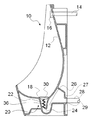
図1に示すように、小便器10は、トイレ空間の床または壁に設置され、使用者の尿を受けるボウル部であるボウル面12を有しており、ボウル面12を洗浄する洗浄水は給水源(図示なし)に接続された給水管14から吐水部16へ供給される。吐水部16は、ボウル部12に洗浄水を吐水し洗浄する。吐水部16はボウル面12の上部に設けられている。ボウル面12の底部には、洗浄水が排水される円形の排水口18が形成されている。排水口18から下方に形成される排水トラップ20は、排水口18から下方に延びる下降流路22と、下降流路22の下端から連続して、下方向から上方向に流路を折り返す折返流路である屈曲部24と、屈曲部24の下流端から上方に延びる上昇流路26とによって一体的に形成される。つまり、排水トラップ20においては、屈曲部24により、排水口18から下向きに流れてきた洗浄水の流れが上向きに変更される。
As shown in FIG. 1, the
排水トラップ20の下部には、下水からの臭気等のトイレ空間への侵入を防ぐため、洗浄水が所定量溜まって溜水が形成されており、この溜水によって排水トラップ20に封水が形成される。つまり、排水トラップ20は、排水口18よりも下流側に封水を形成する。
In order to prevent odors and other odors from entering the toilet space, a predetermined amount of cleaning water is accumulated to form a stored water at the lower part of the
排水トラップ20の上昇流路26の下流側に、洗浄水を小便器10の外部へ排出する排水管路28が設けられている。この排水管路28は、上昇流路26の下流端から連続的に形成されている接続管路27によって、排水トラップ20と接続される。詳細には、接続管路27は、水平方向に排水管路28に向かって延び、排水管路28と接続される接続口29において円筒状の排水管路28と接続されている。排水管路28は、洗浄水が流れやすいように上流側から下流側に向かって緩やかに下り傾斜しつつ、下水管(図示なし)の方向に延びている。なお、接続管路27は排水トラップ20と一体的に形成されているが、樹脂等を用いて別体として成形してもよい。
On the downstream side of the ascending
排水口18には、目皿30が着脱可能に設置される。目皿30は、排水口18の外形に沿った円形の部材である。目皿30は、排水口18よりも少し大きく形成されている。このため、排水口18の縁と目皿30の外縁32が当接することでボウル面12の下部に目皿30が載置される。
An
以上のような構成を備える小便器10において、吐水部16から吐出された洗浄水は、ボウル面12を伝って下方に流れ、目皿30の中央部に形成された複数の小さい開口である小開口34(図2)から排水トラップ20へ流出する。目皿30を載置することで、小開口34より大きい異物が排水トラップ20内に侵入するのを防ぐことができる。更に目皿30の底面には、後述する水流変更手段である螺旋部36が設けられている。
In the
次に図2、図3を参照しつつ、目皿30に設置された螺旋部36について説明する。図2は、目皿30の上面図である。目皿30は、平らな底部を有する円形のお椀のように形成されている。目皿30の下部(底部)の中央部に、洗浄水を排水トラップ20へ流出させるための3つの小開口34が設けられている。小開口34は、目皿30の内底面から下面に貫通するように設けられている。
Next, the
目皿30の下面には、水流変更手段である螺旋部36が一体的に形成されている。螺旋部36の螺旋構造は、目皿30の下面中央から、一定の幅を有する板が、その板面を略上下方向に向けて、半径を目皿30の半径よりも小さい大きさで一定として回転しながら回転面に対して垂直成分の下方向に下降するように延びて形成されている。螺旋部36の螺旋構造は、上面視、反時計回りに3巻分渦巻いている。なお、螺旋構造の幅や巻数は、排水トラップ20の形状や径の大きさから適宜設定するものである。
A
図4に示すように、目皿30をボウル面12の下部に載置すると、目皿30の下部から下方に延びる螺旋部36は、排水トラップ20の下降流路22内に位置する。このように、排水トラップ20の下降流路22内に位置する螺旋部36は、後述のとおり屈曲部24内の外周側を流れる洗浄水を屈曲部24内の内周側に導く。特に、螺旋部36は、排水トラップ20内を流れる洗浄水に旋回流を発生させることで、屈曲部24内の外周側を流れる洗浄水を屈曲部24内の内周側に導く。そして、本実施形態では、螺旋部36は、排水トラップ20内の屈曲部24の上流側に配設され、排水トラップ20の流れ方向を軸として洗浄水を旋回させる螺旋構造として設けられている。なお、本実施形態では、目皿30と一体的に構成された螺旋部36が、排水トラップ20内を流れる洗浄水に旋回流を発生させるための構成として設けられているが、かかる構成としては、螺旋部36のような螺旋状の形状部分に限らず、例えば排水トラップ20の内壁において旋回流を生じさせるように形成された突起部分や突条部分等であってもよい。
As shown in FIG. 4, when the
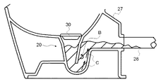
次に螺旋部36を有する目皿30をボウル面12の下部に設置した状態での洗浄水の流れを説明する。吐水部16から吐出された洗浄水は、ボウル面12を伝って下方に流れ、目皿30の小開口34から排水トラップ20に排出される。小開口34から排出された洗浄水が下降流路22内に位置する螺旋部36に沿って流れることで、洗浄水による旋回流が形成される。下降流路22を通ることで螺旋部36によって旋回流となった洗浄水は、屈曲部24の外周側の流れを内周側に導き、上昇流路26を通るときも矢印Aのように旋回したまま排水トラップ20の下流方向へ流れていく。つまり、下降流路22内において螺旋部36により生じた旋回流は、屈曲部24を経た後も維持され、上昇流路26内を進んでいく。なお、旋回流とは、流体が流れ方向に平行なある軸を中心として回転しながら流れる流れのことである。
Next, the flow of the washing water in a state where the
螺旋部36によって排水トラップ20に流入する洗浄水を旋回流とすることで、螺旋部36の無い目皿30を設置した場合、つまり下降流路22内に螺旋部36が存在しない場合と比べて、排水トラップ20の流路内の洗浄水の流れが乱れる。すなわち、螺旋部36によって排水トラップ20内に旋回流を生じさせることで、排水トラップ20内を流れる洗浄水について攪拌作用が得られる。これにより、上昇流路26の屈曲部24直後の流路内周側において発生する淀みを打ち消すことができる。この淀みの原因の一つに、図5に示すように、上昇流路26の一部分の流れが、矢印Bのように逆流してしまうことが挙げられる。詳細には、排水トラップ20内において生じる淀みは、屈曲部24における洗浄水の流れの変化によるものである。屈曲部24を流れる液体のうち、外周側部分を流れる液体は、屈曲部24の外周側の内壁面に沿って矢印Cのように接続管路27へ流れていく。一方、屈曲部24の内周側部分を流れる液体は、ある位置より下流では矢印Bのように逆流する。
By making the washing water flowing into the
従来の排水トラップ20の形状では、排尿後に洗浄水を流して尿濃度の高い液体を置換しようとしても、上昇流路26の一部分において逆流が発生し、その部分において尿濃度の高い液体が淀み、その液体が排出されず排水トラップ20内に残り置換率の低下を招いている。
With the shape of the
そこで旋回流を用いて淀みを解消することが、置換率の向上につながる。そのために螺旋部36を用いて、屈曲部24の内周側を流れる洗浄水は外周側に導かれるように、一方、屈曲部24の外周側を流れる洗浄水は内周側に導かれるように水流を変更することで、流路の流れ方向に対して回転する旋回流を発生させる。これにより、排水トラップ20内の洗浄水が攪拌され、上昇流路26の一部分に発生していた淀みが旋回流によって解消され、尿濃度の高い液体を排水管路28へ排出することで、排水トラップ20内の溜水の置換率を上げることができる。
Therefore, eliminating the stagnation using the swirl flow leads to an improvement in the replacement rate. Therefore, using the
次に他の実施形態について、図6を用いて説明する。この他の実施形態は、螺旋部36に代えて、旋回流を発生させるための水流変更手段を目皿30自体に設けた点で、上述した実施形態と異なる。
Next, another embodiment will be described with reference to FIG. This other embodiment is different from the above-described embodiment in that a water flow changing means for generating a swirling flow is provided in the
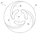
図6に示すように、目皿30の内底面には小開口34が設けられている。小開口34は、円弧状の長穴であり、その円弧状の穴形状を円形の目皿30の外形に沿わせて目皿30の円周方向に等間隔に3つ設けられている。このように複数の小開口34を有する目皿30は、小開口34よりも外側の部分であって略円環状の外周部と、小開口34よりも内側の部分であって略円板状の中央部と、互いに隣り合う小開口34間の部分であって外周部と中央部とを繋ぐ連結部とを有する態様となる。
As shown in FIG. 6, a
目皿30の表面には、小開口34に連続するように、水流変更手段である溝38が形成されている。溝38は、目皿30の中央部に設けられた小開口34の長手方向の一端部から、上面視、目皿30の外縁32に向かって緩やかに時計回りにカーブしている。本実施形態では、各小開口34において1本の溝38が、上面視で小開口34の反時計方向の端部に連続するように設けられている。したがって、目皿30は、3本の溝38を有する。3本の溝38は、上記のとおり緩やかにカーブしており、目皿30の上面視において反時計回りの方向の渦巻状の流れ、つまり旋回流を生じさせる。
A
小便器10に、3本の溝38が形成された目皿30を設置することで洗浄水を旋回流として排水トラップ20に導くことができる。具体的には、吐水部16から吐出された洗浄水は、ボウル面12を伝って、小便器10の下部まで流れ、目皿30の小開口34から排水トラップ20に排出される。小開口34に向かう洗浄水の一部は、目皿30の表面に設けられた溝38を通って小開口34から排出される。溝38に沿って流れた洗浄水は、反時計回りに回転力を得て、旋回流となって小開口34から排水トラップ20に排出される。この旋回流により、上昇流路26の一部分において発生する淀みを打ち消すことができる。
By installing the
更に、他の実施形態について図7、図8を用いて説明する。この他の実施形態は、螺旋部36又は溝38に代えて、屈曲部24の外周側を流れる洗浄水を内周側に導くための水流変更手段を屈曲部24の底部に設けた点で、上述した実施形態と異なる。
Further, another embodiment will be described with reference to FIGS. In this other embodiment, instead of the
水流変更手段である偏向部40は、排水トラップ20の内壁に設けられる。詳細には、偏向部40は、屈曲部24の底部に設けられ、所定の幅を有する板状のもので、屈曲部24の底部から右上方向(図7における右上方向)に向かって、屈曲部24の外形に沿うように曲がりながら延びている。
The
偏向部40によって、屈曲部24の外周側を流れる洗浄水は、偏向部40にぶつかり、矢印Dのように屈曲部24の内周側に導かれるので、淀みが発生する上昇流路26の左側(内側、図8において左側)に洗浄水がぶつかり、淀みを打ち消すことができる。
The washing water flowing on the outer peripheral side of the
以上のように、本実施形態に係る小便器10によれば、水流変更手段を用いて、屈曲部24の外周側を流れる洗浄水を屈曲部24の内周側に導くので、淀みを打ち消し溜水の置換率を上げることができる。
As described above, according to the
以上本発明の実施形態を詳述したがこれはあくまで一例示であり、本発明はその趣旨を逸脱しない範囲において種々変更を加えた形態で構成可能である。 Although the embodiment of the present invention has been described in detail above, this is merely an example, and the present invention can be configured in various forms without departing from the spirit of the present invention.
10 小便器
12 ボウル面
14 給水管
16 吐水部
18 排水口
20 排水トラップ
22 下降流路
24 屈曲部
26 上昇流路
27 接続管路
28 排水管路
29 接続口
30 目皿
32 外縁
34 小開口
36 螺旋部
38 溝
40 偏向部
DESCRIPTION OF
Claims (3)
前記ボウル部に洗浄水を吐水し洗浄する吐水部と、
前記ボウル部の底部に設けられた排水口から下向きに流れてきた洗浄水の流れを上向きに変更する折返流路を有する排水トラップと、
前記排水口に着脱可能に取り付けられる目皿と、
を備え、
前記目皿は水流変更手段を有し、前記水流変更手段は、前記排水トラップにおいて、前記折返流路内の外周側を流れる洗浄水を前記折返流路内の内周側に導くことを特徴とする小便器。 A urinal for washing the bowl with washing water,
A water discharger for discharging and cleaning water in the bowl part;
A drain trap having a return channel for changing upward the flow of washing water flowing downward from a drain outlet provided at the bottom of the bowl portion;
An eye plate removably attached to the drain;
With
The eye dish has a water flow changing means, said water stream changing means Oite the drain trap, guide wolfberry wash water flowing outer peripheral side of the fold-back flow path on the inner peripheral side of the fold-back passage A urinal characterized by.
Priority Applications (1)
| Application Number | Priority Date | Filing Date | Title |
|---|---|---|---|
| JP2013199262A JP6300173B2 (en) | 2013-09-26 | 2013-09-26 | urinal |
Applications Claiming Priority (1)
| Application Number | Priority Date | Filing Date | Title |
|---|---|---|---|
| JP2013199262A JP6300173B2 (en) | 2013-09-26 | 2013-09-26 | urinal |
Publications (3)
| Publication Number | Publication Date |
|---|---|
| JP2015063862A JP2015063862A (en) | 2015-04-09 |
| JP2015063862A5 JP2015063862A5 (en) | 2016-10-13 |
| JP6300173B2 true JP6300173B2 (en) | 2018-03-28 |
Family
ID=52831966
Family Applications (1)
| Application Number | Title | Priority Date | Filing Date |
|---|---|---|---|
| JP2013199262A Active JP6300173B2 (en) | 2013-09-26 | 2013-09-26 | urinal |
Country Status (1)
| Country | Link |
|---|---|
| JP (1) | JP6300173B2 (en) |
Cited By (1)
| Publication number | Priority date | Publication date | Assignee | Title |
|---|---|---|---|---|
| WO2021038195A1 (en) * | 2019-08-28 | 2021-03-04 | FVG Smarti Environmental products Limited | A urinal outlet conduit |
Families Citing this family (1)
| Publication number | Priority date | Publication date | Assignee | Title |
|---|---|---|---|---|
| JP2019060115A (en) * | 2017-09-26 | 2019-04-18 | Toto株式会社 | urinal |
Family Cites Families (1)
| Publication number | Priority date | Publication date | Assignee | Title |
|---|---|---|---|---|
| JP5586301B2 (en) * | 2010-03-31 | 2014-09-10 | 株式会社Lixil | Urinal drain trap |
-
2013
- 2013-09-26 JP JP2013199262A patent/JP6300173B2/en active Active
Cited By (1)
| Publication number | Priority date | Publication date | Assignee | Title |
|---|---|---|---|---|
| WO2021038195A1 (en) * | 2019-08-28 | 2021-03-04 | FVG Smarti Environmental products Limited | A urinal outlet conduit |
Also Published As
| Publication number | Publication date |
|---|---|
| JP2015063862A (en) | 2015-04-09 |
Similar Documents
| Publication | Publication Date | Title |
|---|---|---|
| JP5802959B2 (en) | Flush toilet | |
| KR20100049597A (en) | Rimless toilet with flush water distribution apparatus | |
| CN107201776B (en) | Flush toilet | |
| JP6300173B2 (en) | urinal | |
| JP2017066828A (en) | Water closet | |
| CN107090887B (en) | Flush toilet | |
| JP7055274B2 (en) | Washing toilet | |
| JP2018053460A (en) | Flush toilet bowl | |
| JP5703824B2 (en) | Drain trap | |
| JP6607341B2 (en) | urinal | |
| TWI557297B (en) | Urinals | |
| JP2022173376A (en) | Flush toilet bowl | |
| JP2009167589A (en) | Drain trap | |
| JP5674231B2 (en) | Flush toilet | |
| RU216739U1 (en) | TOILET WITH FLUSH | |
| JP2006124958A (en) | Vanity unit | |
| JP2019173324A (en) | Flush toilet bowl | |
| JP7132551B1 (en) | flush toilet | |
| JP2019060115A (en) | urinal | |
| JP2023110458A (en) | Flush toilet bowl | |
| JP2023102350A (en) | toilet bowl | |
| JP2023136453A (en) | Flush toilet bowl | |
| JP2023102351A (en) | toilet bowl | |
| JP6471848B2 (en) | urinal | |
| JP2022041279A (en) | Water closet |
Legal Events
| Date | Code | Title | Description |
|---|---|---|---|
| A521 | Written amendment |
Free format text: JAPANESE INTERMEDIATE CODE: A523 Effective date: 20160826 |
|
| A621 | Written request for application examination |
Free format text: JAPANESE INTERMEDIATE CODE: A621 Effective date: 20160826 |
|
| A131 | Notification of reasons for refusal |
Free format text: JAPANESE INTERMEDIATE CODE: A131 Effective date: 20170627 |
|
| A521 | Written amendment |
Free format text: JAPANESE INTERMEDIATE CODE: A523 Effective date: 20170823 |
|
| TRDD | Decision of grant or rejection written | ||
| A01 | Written decision to grant a patent or to grant a registration (utility model) |
Free format text: JAPANESE INTERMEDIATE CODE: A01 Effective date: 20180205 |
|
| R150 | Certificate of patent or registration of utility model |
Ref document number: 6300173 Country of ref document: JP Free format text: JAPANESE INTERMEDIATE CODE: R150 |
|
| A61 | First payment of annual fees (during grant procedure) |
Free format text: JAPANESE INTERMEDIATE CODE: A61 Effective date: 20180218 |