JP6295252B2 - Helicopter engine air intake with increased bypass flow - Google Patents
Helicopter engine air intake with increased bypass flow Download PDFInfo
- Publication number
- JP6295252B2 JP6295252B2 JP2015524828A JP2015524828A JP6295252B2 JP 6295252 B2 JP6295252 B2 JP 6295252B2 JP 2015524828 A JP2015524828 A JP 2015524828A JP 2015524828 A JP2015524828 A JP 2015524828A JP 6295252 B2 JP6295252 B2 JP 6295252B2
- Authority
- JP
- Japan
- Prior art keywords
- grid
- air intake
- intake
- lip
- icing
- Prior art date
- Legal status (The legal status is an assumption and is not a legal conclusion. Google has not performed a legal analysis and makes no representation as to the accuracy of the status listed.)
- Expired - Fee Related
Links
- 239000002184 metal Substances 0.000 claims description 21
- 239000000853 adhesive Substances 0.000 claims description 5
- 230000001070 adhesive effect Effects 0.000 claims description 5
- 238000011144 upstream manufacturing Methods 0.000 claims description 5
- 238000005219 brazing Methods 0.000 claims description 4
- 239000002131 composite material Substances 0.000 description 6
- 239000000463 material Substances 0.000 description 5
- 238000010586 diagram Methods 0.000 description 4
- 239000007789 gas Substances 0.000 description 4
- 238000002485 combustion reaction Methods 0.000 description 3
- 239000011343 solid material Substances 0.000 description 3
- 239000000243 solution Substances 0.000 description 3
- 230000005540 biological transmission Effects 0.000 description 2
- 238000002788 crimping Methods 0.000 description 2
- 239000000446 fuel Substances 0.000 description 2
- 229910001220 stainless steel Inorganic materials 0.000 description 2
- 239000010935 stainless steel Substances 0.000 description 2
- 239000011324 bead Substances 0.000 description 1
- 239000000567 combustion gas Substances 0.000 description 1
- 238000002347 injection Methods 0.000 description 1
- 239000007924 injection Substances 0.000 description 1
- 238000000034 method Methods 0.000 description 1
- 230000003014 reinforcing effect Effects 0.000 description 1
- 238000003466 welding Methods 0.000 description 1
Images


Classifications
-
- B—PERFORMING OPERATIONS; TRANSPORTING
- B64—AIRCRAFT; AVIATION; COSMONAUTICS
- B64D—EQUIPMENT FOR FITTING IN OR TO AIRCRAFT; FLIGHT SUITS; PARACHUTES; ARRANGEMENT OR MOUNTING OF POWER PLANTS OR PROPULSION TRANSMISSIONS IN AIRCRAFT
- B64D33/00—Arrangements in aircraft of power plant parts or auxiliaries not otherwise provided for
- B64D33/02—Arrangements in aircraft of power plant parts or auxiliaries not otherwise provided for of combustion air intakes
-
- F—MECHANICAL ENGINEERING; LIGHTING; HEATING; WEAPONS; BLASTING
- F02—COMBUSTION ENGINES; HOT-GAS OR COMBUSTION-PRODUCT ENGINE PLANTS
- F02C—GAS-TURBINE PLANTS; AIR INTAKES FOR JET-PROPULSION PLANTS; CONTROLLING FUEL SUPPLY IN AIR-BREATHING JET-PROPULSION PLANTS
- F02C7/00—Features, components parts, details or accessories, not provided for in, or of interest apart form groups F02C1/00 - F02C6/00; Air intakes for jet-propulsion plants
- F02C7/04—Air intakes for gas-turbine plants or jet-propulsion plants
- F02C7/05—Air intakes for gas-turbine plants or jet-propulsion plants having provisions for obviating the penetration of damaging objects or particles
- F02C7/055—Air intakes for gas-turbine plants or jet-propulsion plants having provisions for obviating the penetration of damaging objects or particles with intake grids, screens or guards
-
- B—PERFORMING OPERATIONS; TRANSPORTING
- B64—AIRCRAFT; AVIATION; COSMONAUTICS
- B64D—EQUIPMENT FOR FITTING IN OR TO AIRCRAFT; FLIGHT SUITS; PARACHUTES; ARRANGEMENT OR MOUNTING OF POWER PLANTS OR PROPULSION TRANSMISSIONS IN AIRCRAFT
- B64D33/00—Arrangements in aircraft of power plant parts or auxiliaries not otherwise provided for
- B64D33/02—Arrangements in aircraft of power plant parts or auxiliaries not otherwise provided for of combustion air intakes
- B64D2033/022—Arrangements in aircraft of power plant parts or auxiliaries not otherwise provided for of combustion air intakes comprising bird or foreign object protections
-
- B—PERFORMING OPERATIONS; TRANSPORTING
- B64—AIRCRAFT; AVIATION; COSMONAUTICS
- B64D—EQUIPMENT FOR FITTING IN OR TO AIRCRAFT; FLIGHT SUITS; PARACHUTES; ARRANGEMENT OR MOUNTING OF POWER PLANTS OR PROPULSION TRANSMISSIONS IN AIRCRAFT
- B64D33/00—Arrangements in aircraft of power plant parts or auxiliaries not otherwise provided for
- B64D33/02—Arrangements in aircraft of power plant parts or auxiliaries not otherwise provided for of combustion air intakes
- B64D2033/0233—Arrangements in aircraft of power plant parts or auxiliaries not otherwise provided for of combustion air intakes comprising de-icing means
-
- B—PERFORMING OPERATIONS; TRANSPORTING
- B64—AIRCRAFT; AVIATION; COSMONAUTICS
- B64D—EQUIPMENT FOR FITTING IN OR TO AIRCRAFT; FLIGHT SUITS; PARACHUTES; ARRANGEMENT OR MOUNTING OF POWER PLANTS OR PROPULSION TRANSMISSIONS IN AIRCRAFT
- B64D33/00—Arrangements in aircraft of power plant parts or auxiliaries not otherwise provided for
- B64D33/02—Arrangements in aircraft of power plant parts or auxiliaries not otherwise provided for of combustion air intakes
- B64D2033/0253—Arrangements in aircraft of power plant parts or auxiliaries not otherwise provided for of combustion air intakes specially adapted for particular type of aircraft
-
- F—MECHANICAL ENGINEERING; LIGHTING; HEATING; WEAPONS; BLASTING
- F05—INDEXING SCHEMES RELATING TO ENGINES OR PUMPS IN VARIOUS SUBCLASSES OF CLASSES F01-F04
- F05D—INDEXING SCHEME FOR ASPECTS RELATING TO NON-POSITIVE-DISPLACEMENT MACHINES OR ENGINES, GAS-TURBINES OR JET-PROPULSION PLANTS
- F05D2220/00—Application
- F05D2220/30—Application in turbines
- F05D2220/32—Application in turbines in gas turbines
- F05D2220/329—Application in turbines in gas turbines in helicopters
-
- Y—GENERAL TAGGING OF NEW TECHNOLOGICAL DEVELOPMENTS; GENERAL TAGGING OF CROSS-SECTIONAL TECHNOLOGIES SPANNING OVER SEVERAL SECTIONS OF THE IPC; TECHNICAL SUBJECTS COVERED BY FORMER USPC CROSS-REFERENCE ART COLLECTIONS [XRACs] AND DIGESTS
- Y02—TECHNOLOGIES OR APPLICATIONS FOR MITIGATION OR ADAPTATION AGAINST CLIMATE CHANGE
- Y02T—CLIMATE CHANGE MITIGATION TECHNOLOGIES RELATED TO TRANSPORTATION
- Y02T50/00—Aeronautics or air transport
- Y02T50/60—Efficient propulsion technologies, e.g. for aircraft
Landscapes
- Engineering & Computer Science (AREA)
- Chemical & Material Sciences (AREA)
- Combustion & Propulsion (AREA)
- Mechanical Engineering (AREA)
- General Engineering & Computer Science (AREA)
- Aviation & Aerospace Engineering (AREA)
- Structures Of Non-Positive Displacement Pumps (AREA)
- Cooling, Air Intake And Gas Exhaust, And Fuel Tank Arrangements In Propulsion Units (AREA)
Description
本発明は、ヘリコプタエンジン用の空気取入口に関し、取入口には、万一着氷の場合には大量のバイパス流れを提供する防氷グリッドが設けられる。 The present invention relates to an air intake for a helicopter engine, and the intake is provided with an anti-icing grid that provides a large amount of bypass flow in the event of icing.
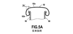
着氷条件下で作動中に、空気取入口に、かつエンジンの空気供給通路にできる氷の危険を防止するために、現在の空気取入口には、エンジンの中への空気取入口開口を完全に覆う防氷グリッドが設けられる。これは、特に、図5Aに示されるように、Turbomeca TM−333エンジンに適用される。グリッドは、着氷がたとえあったとしてもむしろ空気取入口自体にまたは空気供給通路よりも、グリッド92の外表面92aにできるということを確実にする。この場合、グリッド92の内側部分92bは、これが着氷される場合にはバイパス空気がグリッド92の外表面92aの周りに流れることができるように設けられる。
To prevent the risk of ice in the air intake and in the engine air supply passage when operating under icing conditions, the current air intake has a complete air intake opening into the engine. An anti-icing grid is provided. This applies in particular to the Turbomeca TM-333 engine, as shown in FIG. 5A. The grid ensures that icing can occur on the
それにもかかわらず、今日のエンジンにおいては、防氷グリッド92が取り付けられている吸気リップ90は、通常、TM−333エンジンの場合のように、中実材料に機械加工され、さもなければ、これらは複合材料で作られ、したがって特に嵩張る。空気取入口の周りの空間の欠如を仮定すると、この場合、グリッド92の外表面92aが着氷しているときに依然として利用できるバイパス部Sc′は小さく、それにより、万一着氷の場合には空気の流量が制限されるということが分かる。
Nevertheless, in today's engines, the
加えて、中実材料に機械加工されるモデルと複合材料から作られるモデルは共に、組み立ての難しさを有する。特に複合材料の場合、グリッドの縁は、複合リップに次々に接着接合される断面部材に接着接合され、この種の組立作業の複雑さに加えて、現在は、複合材料に対して接着剤を使用することは困難である。 In addition, both models machined into solid materials and models made from composite materials have difficulty in assembling. In particular in the case of composite materials, the edges of the grid are adhesively bonded to cross-section members that are in turn adhesively bonded to the composite lip, and in addition to the complexity of this kind of assembly operation, now the adhesive is applied to the composite material. It is difficult to use.
万一着氷の場合にはかなりの量のバイパス流れを提供し、上に記述した従来技術の空気取入口に固有の欠点を回避する、ヘリコプタエンジン空気取入口の真の必要性が存在する。 In the unlikely event of icing, there is a real need for a helicopter engine air intake that provides a significant amount of bypass flow and avoids the disadvantages inherent in the prior art air intake described above.
本説明は、圧縮機と、圧縮機に空気を供給するための通路とを有するガスタービンヘリコプタエンジン用の空気取入口であって、その通路が、前記空気取入口を介してその上流側端部に通じ、空気取入口が、吸気リップと、吸気リップの外側端部に取り付けられる防氷グリッドであり、空気取入口に入り込む空気流に介在される防氷グリッドとを備え、少なくとも1つの吸気リップが、金属薄板によって成形される、空気取入口に関する。 The present description relates to an air intake for a gas turbine helicopter engine having a compressor and a passage for supplying air to the compressor, the passage being connected to the upstream end thereof via the air intake. At least one intake lip comprising an intake lip and an anti-icing grid attached to an outer end of the intake lip, and an anti-icing grid interposed in an air flow entering the air intake. Relates to an air intake formed by a sheet metal.
前記吸気リップを作るために金属薄板を用いることによって、非常に小さな厚さから成る吸気リップが利用可能となり、それによって、所与の利用可能な外側空間について、大きな自由体積が、防氷グリッド内に大きなバイパス部をその中に設けるように利用可能に残される。したがって、万一グリッドの外表面の着氷の場合には、空気流量が通常の作動条件と比べて少しだけ低減されるバイパス流れを可能にするような、十分なサイズから成るグリッドの一部が依然として利用可能である。 By using a sheet metal to make the air intake lip, an air intake lip of very small thickness is made available, so that for a given available outer space, a large free volume is provided within the anti-icing grid. A large bypass is left available to be provided therein. Thus, in the unlikely event of icing on the outer surface of the grid, a portion of the grid that is sufficiently sized to allow a bypass flow in which the air flow is slightly reduced compared to normal operating conditions. Still available.
特に、非常に良好な造形性または成形性を有する金属薄板を用いることによって、複雑でコンパクトな形状を使用することができる。なぜなら、この種の金属シートは、非常に小さな曲率半径で使用され得るからである。したがって、吸気リップにグリッドを組み立てることがより容易になり、特にグリッドトリップとの間のより大きな近接、およびしたがってより大きなコンパクトさを有することが可能になる。また、金属薄板を使用すると、他の材料の場合は可能でない、溶接などのある締結技術を用いることができる。 In particular, by using a thin metal plate having very good formability or formability, a complicated and compact shape can be used. This is because this type of metal sheet can be used with very small radii of curvature. Thus, it becomes easier to assemble the grid on the intake lip, and in particular it is possible to have a greater proximity to the grid trip and thus a greater compactness. In addition, when a thin metal plate is used, a certain fastening technique such as welding, which is not possible with other materials, can be used.
そのうえ、金属薄板は、小さな重量という利点を提供し、それによって、エンジンの燃料消費を低減することによって作動コストができるようになる。ある実施形態においては、前記少なくとも1つの吸気リップを成形する前記金属薄板は、1.5ミリメートル(mm)未満、および好ましくは0.8mm未満の厚さをもつ。 Moreover, sheet metal offers the advantage of low weight, thereby allowing operating costs by reducing engine fuel consumption. In an embodiment, the sheet metal forming the at least one intake lip has a thickness of less than 1.5 millimeters (mm), and preferably less than 0.8 mm.
ある実施形態においては、前記少なくとも1つの吸気リップの外側端部は、U字形状に外側に湾曲され、防氷グリッドの縁は、このように画定されるU字形状の空間に係合される。金属シートの成形性のために、非常に狭い、かつグリッドの縁の寸法にうまく適応しているU字形状の空間を画定することができる。加えて、これらの成形性のために、この種のU字形状の空間は、リップ自体に非常に近接して形成されることができ、それによって、バイパス部を増加させるのに寄与し得る大量の横空間を解放する働きをする。 In one embodiment, the outer end of the at least one intake lip is curved outward in a U-shape, and the edge of the anti-icing grid is engaged in the U-shaped space thus defined. . Because of the formability of the metal sheet, it is possible to define a U-shaped space that is very narrow and well adapted to the dimensions of the grid edges. In addition, due to their formability, this type of U-shaped space can be formed very close to the lip itself, thereby contributing to increasing the bypass section. It works to release the horizontal space.
ある実施形態においては、防氷グリッドの縁は、吸気リップによって画定されるU字形状の空間の壁にぴったりと嵌合している。これにより、特に、このU字形状の空間にグリッドの縁を圧着し、またはスタンピングによってこれらの部品を一緒に組み立てることができる。 In some embodiments, the edge of the anti-icing grid fits snugly into the wall of the U-shaped space defined by the intake lip. This makes it possible in particular to assemble these parts together by crimping the edges of the grid in this U-shaped space or by stamping.
ある実施形態においては、防氷グリッドの縁には、前記少なくとも1つの吸気リップに締結されるファスナータブが設けられる。このアセンブリ解決策は、金属シートの成形性によって可能になるコンパクトさおよび近接性自体によって可能になるが、単純性および信頼性の点から利点を提供する。この種のファスナータブは、すべての吸気リップに沿って任意選択的に規則的な間隔で設けられ得る。 In one embodiment, an edge of the anti-icing grid is provided with a fastener tab fastened to the at least one intake lip. This assembly solution is enabled by the compactness and proximity itself enabled by the formability of the metal sheet, but offers advantages in terms of simplicity and reliability. Such fastener tabs can optionally be provided at regular intervals along all intake lips.
ある実施形態においては、防氷グリッドの縁には、前記少なくとも1つの吸気リップに締結される連続ファスナービードが設けられる。このアセンブリ解決策により、締結がリップのすべてのセグメントに沿って、またはすべてのリップ全体に沿って実現できるようになる。 In one embodiment, the edge of the anti-icing grid is provided with a continuous fastener bead fastened to the at least one intake lip. This assembly solution allows fastening to be achieved along all segments of the lip or along the entire lip.
ある実施形態においては、防氷グリッドの縁は、溶接部によって前記少なくとも1つの吸気リップに締結される。この締結は、信頼性があり耐久性がある。 In an embodiment, the edge of the anti-icing grid is fastened to the at least one intake lip by a weld. This fastening is reliable and durable.
他の実施形態においては、防氷グリッドの縁は、ろう付けによって、接着剤のスポットによって、圧着によって、またはそれどころかリベットによって前記少なくとも1つの吸気リップに締結される。 In other embodiments, the edge of the anti-icing grid is fastened to the at least one intake lip by brazing, by an adhesive spot, by crimping, or even by rivets.
ある実施形態においては、前記少なくとも1つの吸気リップへの前記防氷グリッドの締結は、接着剤接合を含まない。したがって、接着剤技術を用いる困難さが回避される。 In some embodiments, fastening of the anti-icing grid to the at least one intake lip does not include an adhesive joint. Thus, the difficulty of using adhesive technology is avoided.
ある実施形態においては、グリッドの縁は、防氷グリッドの本体と別個の部品であり、グリッドの縁は、グリッドの本体に締結される。この解決策により、接合を形成するために、および防氷グリッド上の吸気リップに締結されるために特に設計され、単に着氷を回避し大きなバイパス部を形成する目的でそれ自体成形される、ファスナーインターフェースに適合させることが容易になる。特に、縁の材料は、グリッドの本体の材料と異なってもよく、たとえば、縁は、プラスチック材料で作られることができるが、一方グリッドの本体は、金属で作られる。 In certain embodiments, the edge of the grid is a separate piece from the body of the anti-icing grid, and the edge of the grid is fastened to the body of the grid. With this solution, it is specially designed to form a joint and to be fastened to the intake lip on the anti-icing grid, and is itself molded for the purpose of simply avoiding icing and forming a large bypass, It is easy to adapt to the fastener interface. In particular, the material of the edge may be different from the material of the body of the grid, for example, the edge can be made of a plastic material, while the body of the grid is made of metal.
ある実施形態においては、グリッドの縁は、ろう付けによって防氷グリッドの本体に締結される。 In some embodiments, the edge of the grid is fastened to the body of the anti-icing grid by brazing.
ある実施形態においては、吸気リップは、90°より大きい、および好ましくは180°に等しい角度セクタにわたって単一体として作られる。 In some embodiments, the intake lip is made as a unit over an angular sector greater than 90 ° and preferably equal to 180 °.
ある実施形態においては、両方の吸気リップは、金属薄板で作られる。 In some embodiments, both intake lips are made of sheet metal.
ある実施形態においては、空気取入口は、ラジアル型から成る。 In some embodiments, the air intake is of a radial type.
ある実施形態においては、空気取入口は、アキシャル型から成る。 In some embodiments, the air intake is of an axial type.
また、本発明は、上に記述した実施形態のいずれかに記載の空気取入口を有する、ガスタービンヘリコプタエンジンを提供する。 The present invention also provides a gas turbine helicopter engine having an air intake according to any of the embodiments described above.
上に挙げた特徴および利点、および他のものは、提案された空気取入口の実施形態ついて次の詳細な説明を読むと明らかになる。この詳細な説明は、添付の図面を参照して行われる。 The features and advantages listed above, as well as others, will become apparent upon reading the following detailed description of the proposed air intake embodiments. This detailed description is made with reference to the accompanying drawings.
添付の図面は、概略であり、とりわけ本発明の原理を示そうと努めている。 The accompanying drawings are schematic and strive, inter alia, to illustrate the principles of the invention.
図面においては、ある図から別の図まで、同一の要素(または、要素の部分)は、同じ参照符号を用いて参照される。 In the drawings, from one figure to another, identical elements (or parts of elements) are referred to with the same reference numerals.
本発明をより具体的にするために、本発明の実施例の空気取入口が、添付の図面を参照して下記に詳細に説明される。本発明はこの実施例に限定されないことを想起されたい。 In order to make the present invention more specific, an air intake port according to an embodiment of the present invention will be described in detail below with reference to the accompanying drawings. It should be recalled that the present invention is not limited to this example.
図1は、環状空気供給通路12を介して外気を受け入れる圧縮機段10(たとえば、遠心圧縮機)を有するガスタービンヘリコプタエンジンの概念図である。その上流側端部において、通路12は、エンジンの金属ケーシング14によって画定される環状外側開口12aを介して開く。また、ケーシング14は、通路12の壁を画定する。環状燃焼室16、たとえば逆流燃焼室には、燃料と、圧縮機10から来る一次空気の流れとが供給される噴射装置(図示せず)が設けられる。燃焼室16からの燃焼ガスは、圧縮機10を駆動しシャフト20によってそれに連結されるタービン18に、かつまた、シャフト23によって伝動装置に連結される(たとえば、単一段を有する)出力タービン22に入り、この伝動装置は、機械的動力を出口シャフト24に供給し、シャフト20および23は同軸である。
FIG. 1 is a conceptual diagram of a gas turbine helicopter engine having a compressor stage 10 (eg, a centrifugal compressor) that receives outside air via an annular
図2に示されるように、2つのリップ30および32(図1には図示せず)が、通路12用の空気取入口34を画定する。リップ30および32は、2つのそれぞれの環状金属薄板によって成形され、この環状金属薄板は、開口12aの両側に、かつすべてのそれに沿って通路12の上流側端部に内側端部において連結する。この実施例においては、リップ30および32を成形する金属シートは、溶接可能な金属、たとえばステンレス鋼で作られ、これらは、約0.6mmの厚さをもつ。これらの両端、または外側端部において、リップ30および32は、U字形状の空間70を形成するようにU字形に外側に湾曲されるそれぞれのリム30aおよび32aを有する。これらの内側端部において、リップ30および32は、それらをケーシング14に締結されることを可能にする実質的に90°で折り返されるタブもしくはカラー30bおよび32bを有することができる。
As shown in FIG. 2, two
リム30aおよび32aによって画定される空気取入口34の端部34aは、金属の防氷グリッド36によって覆われ、この金属は、成形可能で強い、たとえばステンレス鋼であり、これらのリムの端部がリム30aおよび32aのU字形状の空間70に係合するように、リップ30および32に対して湾曲されるリムを有する。グリッド36の目的は、できる限りグリッド36の外表面36aに氷を形成して、空気取入口34および供給通路12の内側にできる氷を回避することである。次いで、環状バイパスチャネル38が、グリッド36の外表面36aの着氷にもかかわらず十分な空気を通路12に供給するように設けられる。チャネル38は、補強リブ39aが設けられケーシング14に固定される環状壁傾斜ガイド39またはプレナムによって一方の側面に画定される。壁39は、チャネル38の他方の側面を画定する空気取入口のリップの一方、たとえばリップ32に面して位置している。また、類似の第2のバイパスチャネル40が、もう一方のリップ30のそばに設けられる(それにもかかわらず、そのプレナムは図面を煩雑化させることを回避するために示されていない)。防氷グリッド36の湾曲リムは、空気取入口34の両側に内部バイパス表面36bを画定し、ケーシング14に面し、したがってバイパスチャネル38または40に通じ、それによって、グリッド36の外表面36aが氷結される場合にはバイパス空気の流れを流入できるようにする。リップ30、32と防氷グリッド36との間で横方向に画定されるバイパス部Scは、このバイパス気流の最大流量を決定する。
The
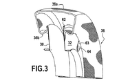
図3においては、各リップ30、32は、大きな角度セクタにわたって一体に作られることができ、通常、90°より大きく占めるということが理解できる。この実施形態においては、空気取入口34は、それぞれ180°を占める2つの上流リップ30を有し、そのリップは、360°にわたって空気取入口34を形成するように互いに接触し、類似の方法で、空気取入口34は、同様に、それぞれ180°にわたって延在する2つの下流リップ32を有する。ところで、この実施形態のリップ30および32は、それらのリム30a、32aとそれらのタブまたはカラー30b、32bとの間に実質的に矩形の断面の輪郭をもつということを認められたい。それにもかかわらず、他の実施形態においては、この輪郭は、リップ30、32の一方および/またはもう一方に対して湾曲されることもできる。
In FIG. 3, it can be seen that each
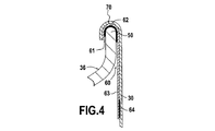
図3および図4により、いかにグリッド36がリップ30、32に組み立てられるかを可視化することがより容易になる。お分かりのように、グリッド36の側方端縁50は、リップ30、32の各々のU字形状の空間70の方へ湾曲され、縁60は、グリッド36とリップ30、32との間の締結インターフェースとして役立つようにこれらの縁50の各々に沿って取り付けられる。
3 and 4 make it easier to visualize how the
この縁60は、リップ30または32と同じ金属から作られる溝形断面部材から成り、グリッド36の縁50の円周方向全周に延在し、したがって、グリッド36の側方端縁50が受け入れられる溝61を形成し、これは、ろう付け62によってそれに締結される。
This
規則的な間隔で、縁60はまた、ケーシング14の方へ溝61の内側端縁に合わせて半径方向に延在するファスナータブ63を有する。このように、グリッド36の端縁50は、縁60の溝61に締結され、縁60は、リップ30、32のU字形状の空間70に受け入れられ、ファスナータブ63は、リップ30、32の外壁に沿って延在する。次に、ファスナータブ63は、スポット溶接部64によってリップ30、32の壁に対して締結される。ファスナータブ63は、グリッド36をリップ30、32に組み立てる場合に工具が通過できるようになっているように、防氷グリッド36の内部バイパス表面36bのレベルよりも低いレベルまでリップ30、32に沿って下降するように十分な長さから成る。
At regular intervals, the
金属薄板を用いることによって、リップ30、32は、それ自体非常にコンパクトであり、グリッド36は、リップ30、32に非常にコンパクトな方法で組み立てられることができる。したがって、所与の全体的サイズについて、大きなバイパス部Scを提供することができる。
By using sheet metal, the
図5Bは、従来技術の従来の空気取入口と比べてこの種の空気取入口によって可能になるバイバス部の増加を示す概念図である。この図においては、本発明の空気取入口は、連続する線で概略的に描かれているが、従来技術の空気取入口は、破線で描かれている。 FIG. 5B is a conceptual diagram illustrating the increase in bypass portion enabled by this type of air intake compared to a conventional air intake of the prior art. In this figure, the air intake of the present invention is schematically depicted by a continuous line, whereas the prior art air intake is depicted by a dashed line.
従来技術の空気取入口においては、中実材料に機械加工され、または複合材料で作られるリップ90は、より肉厚である。加えて、材料は、グリッド92の側方端縁93が受け入れられるリップ90のリムによって形成されるU字形状の空間91が、通常約5mmから約10mmの範囲にある大きな曲率半径R′を有するように、成形するのは困難である。したがって、従来技術の空気取入口においては、リップ90とグリッド92との間のバイバス部Sc′はより小さい。
In prior art air intakes, the
対照的に、本発明の空気取入口においては、リップ30、32は、より優れており、金属シートの良好な成形性のために遥かに小さな曲率半径Rを有するU字形の形状70を成形し、したがって、約2mmまたはさらに小さい曲率半径Rを得ることができる。このような環境下では、グリッド36の側方端縁50は、リップ30、32の壁に遥かに接近して、すなわち空気取入口の中心平面に遥かに接近してリップ30、32に取り付けられ得る。したがって、本発明の空気取入口においては、リップ30、32とグリッド36との間のバイバス部Scは、従来技術の空気取入口の場合よりも大きい。
In contrast, in the air intake of the present invention, the
本説明において記述した実施形態は、非限定的な例示として与えられており、本説明に照らして、当業者は、これらの実施形態を容易に変更することができ、または本発明の範囲内にとどまりながら他のものを想到することができる。 The embodiments described in this description are given as non-limiting examples, and in light of this description, those skilled in the art can easily modify these embodiments or are within the scope of the present invention. You can come up with other things while staying.
特に、上記の詳細な説明においては、空気取入口リップは、エンジンの外周全体にわたって空気供給通路の環状開口12aに沿って延在する。それにもかかわらず、本発明はまた、空気供給通路の外側開口がエンジンの外周の一部分のみにわたって延在する場合にも適用できる。同様に、本発明はまた、空気供給通路が軸線方向であり、半径方向でない外側開口を有する場合にも適用できる。加えて、上記の説明は、ヘリコプタの実施例を用いているが、本発明は、もちろんバイパス装置を有するグリッドが設けられる空気取入口を有する任意の他のガスタービンに置換され得る。
In particular, in the detailed description above, the air intake lip extends along the
そのうえ、これらの実施形態のさまざまな特徴は、単独で使用されることができ、または、互いに組み合わされ得る。これらが組み合わされる場合には、特徴は、上記で説明したようにまたは他の方法で組み合わされることができ、本発明は、本説明で説明された特定の組合せに限定されるものではない。特に、それと反対の指定がない限り、任意の1つの特定の実施形態を参照して説明された特徴は、任意の他の実施形態に類似の方法で適用され得る。 Moreover, the various features of these embodiments can be used alone or in combination with each other. When combined, the features can be combined as described above or in other ways, and the invention is not limited to the specific combinations described in the description. In particular, unless otherwise specified, features described with reference to any one particular embodiment may be applied in a manner similar to any other embodiment.
Claims (10)
吸気リップ(30、32)と、
吸気リップ(30、32)の外側端部(30a、32a)に取り付けられる防氷グリッド(36)であり、空気取入口(34)に入り込む空気流に介在される防氷グリッド(36)と
を備える空気取入口であって、
少なくとも1つの吸気リップ(30、32)が、金属薄板によって成形されることを特徴とする、空気取入口。 An air intake for a gas turbine helicopter engine having a compressor (10) and a passage (12) for supplying air to the compressor (10), the passage through the air intake (34) To the upstream end of the
An intake lip (30, 32);
An anti-icing grid (36) attached to the outer end (30a, 32a) of the intake lip (30, 32), and an anti-icing grid (36) interposed in the air flow entering the air intake (34). An air intake provided,
Air intake, characterized in that at least one intake lip (30, 32) is formed by sheet metal.
Applications Claiming Priority (3)
| Application Number | Priority Date | Filing Date | Title |
|---|---|---|---|
| FR1257385 | 2012-07-30 | ||
| FR1257385A FR2993862B1 (en) | 2012-07-30 | 2012-07-30 | AIR INLET FOR HELICOPTER ENGINE WITH INCREASED BYPASS CIRCULATION |
| PCT/FR2013/051809 WO2014020267A1 (en) | 2012-07-30 | 2013-07-26 | Helicopter engine air intake with improved bypass flow |
Publications (2)
| Publication Number | Publication Date |
|---|---|
| JP2015527525A JP2015527525A (en) | 2015-09-17 |
| JP6295252B2 true JP6295252B2 (en) | 2018-03-14 |
Family
ID=47178073
Family Applications (1)
| Application Number | Title | Priority Date | Filing Date |
|---|---|---|---|
| JP2015524828A Expired - Fee Related JP6295252B2 (en) | 2012-07-30 | 2013-07-26 | Helicopter engine air intake with increased bypass flow |
Country Status (11)
| Country | Link |
|---|---|
| US (1) | US10071813B2 (en) |
| EP (1) | EP2879955B1 (en) |
| JP (1) | JP6295252B2 (en) |
| KR (1) | KR102180839B1 (en) |
| CN (1) | CN104507810B (en) |
| CA (1) | CA2879517C (en) |
| FR (1) | FR2993862B1 (en) |
| IN (1) | IN2015DN00616A (en) |
| PL (1) | PL2879955T3 (en) |
| RU (1) | RU2638055C2 (en) |
| WO (1) | WO2014020267A1 (en) |
Families Citing this family (3)
| Publication number | Priority date | Publication date | Assignee | Title |
|---|---|---|---|---|
| US10036320B2 (en) | 2015-11-20 | 2018-07-31 | Bell Helicopter Textron Inc. | Passive internal ice protection systems for engine inlets |
| CN107120193B (en) * | 2017-06-28 | 2024-05-03 | 李兵长 | Engine air inlet device for helicopter and helicopter |
| KR20220146163A (en) | 2021-04-23 | 2022-11-01 | 현대자동차주식회사 | Hybrid airmobility system |
Family Cites Families (19)
| Publication number | Priority date | Publication date | Assignee | Title |
|---|---|---|---|---|
| US3764307A (en) * | 1972-08-04 | 1973-10-09 | Gen Electric | Ni au base brazing alloy |
| US3871844A (en) * | 1973-09-28 | 1975-03-18 | Sr Frank F Calvin | Screen apparatus for air inlet |
| GB1474390A (en) * | 1974-09-27 | 1977-05-25 | Secr Defence | Debris guard |
| US4006999A (en) * | 1975-07-17 | 1977-02-08 | The United States Of America As Represented By The Administrator Of The National Aeronautics And Space Administration | Leading edge protection for composite blades |
| JPS5330006U (en) * | 1977-08-02 | 1978-03-15 | ||
| JPS5948298A (en) * | 1982-09-11 | 1984-03-19 | 川崎重工業株式会社 | Preventive net for suction of foreign matter of air intake |
| DE4340951A1 (en) * | 1992-12-04 | 1994-06-09 | Grumman Aerospace Corp | One-piece engine inlet sound tube |
| RU2059963C1 (en) | 1993-07-05 | 1996-05-10 | Конструкторское бюро приборостроения | Guided rocket |
| US5433070A (en) * | 1993-09-08 | 1995-07-18 | United Technologies Corporation | Flexible engine inlet duct mounting system |
| FR2723761B1 (en) * | 1994-08-18 | 1996-09-20 | Snecma | TURBOREACTOR EQUIPPED WITH A DEFROST SYSTEM ON THE INPUT HOUSING |
| FR2757823B1 (en) | 1996-12-26 | 1999-03-12 | Aerospatiale | LAMINARY FLOW TURBOREACTOR BASKET |
| DE10000418A1 (en) * | 2000-01-07 | 2001-08-09 | Abb Turbo Systems Ag Baden | Compressor of an exhaust gas turbocharger |
| US6595742B2 (en) * | 2000-10-02 | 2003-07-22 | Westar Corporation | Aircraft engine air filter and method |
| US7131612B2 (en) | 2003-07-29 | 2006-11-07 | Pratt & Whitney Canada Corp. | Nacelle inlet lip anti-icing with engine oil |
| FR2905983B1 (en) * | 2006-09-20 | 2013-03-15 | Turbomeca | DEVICE FOR SOUNDPROOFING A GAS TURBINE HELICOPTER ENGINE AND THE MOTOR THUS OBTAINED |
| FR2914016B1 (en) * | 2007-03-19 | 2009-07-03 | Turbomeca Sa | DEVICE FOR DEFROSTING AN AIR INTAKE OF A GAS TURBINE |
| RU2348570C1 (en) | 2007-09-04 | 2009-03-10 | Открытое акционерное общество Центральный научно-исследовательский институт специального машиностроения | Method of making aircraft engine air intake from laminar composite materials and aircraft engine air intake |
| FR2936777B1 (en) | 2008-10-08 | 2010-10-22 | Aircelle Sa | AIR INTAKE STRUCTURE FOR A NACELLE FOR TURBOJET ENGINE |
| EP2282031B1 (en) * | 2009-07-02 | 2012-06-06 | Eurocopter Deutschland GmbH | Filtering device with integrated bypass for an air inlet |
-
2012
- 2012-07-30 FR FR1257385A patent/FR2993862B1/en active Active
-
2013
- 2013-07-26 PL PL13756606T patent/PL2879955T3/en unknown
- 2013-07-26 US US14/417,225 patent/US10071813B2/en active Active
- 2013-07-26 RU RU2015106685A patent/RU2638055C2/en active
- 2013-07-26 CN CN201380039984.8A patent/CN104507810B/en active Active
- 2013-07-26 CA CA2879517A patent/CA2879517C/en not_active Expired - Fee Related
- 2013-07-26 EP EP13756606.3A patent/EP2879955B1/en active Active
- 2013-07-26 IN IN616DEN2015 patent/IN2015DN00616A/en unknown
- 2013-07-26 WO PCT/FR2013/051809 patent/WO2014020267A1/en active Application Filing
- 2013-07-26 JP JP2015524828A patent/JP6295252B2/en not_active Expired - Fee Related
- 2013-07-26 KR KR1020157002008A patent/KR102180839B1/en active IP Right Grant
Also Published As
| Publication number | Publication date |
|---|---|
| IN2015DN00616A (en) | 2015-08-21 |
| EP2879955B1 (en) | 2020-02-26 |
| RU2638055C2 (en) | 2017-12-11 |
| RU2015106685A (en) | 2016-09-20 |
| KR102180839B1 (en) | 2020-11-19 |
| CN104507810B (en) | 2020-04-28 |
| KR20150037894A (en) | 2015-04-08 |
| US10071813B2 (en) | 2018-09-11 |
| WO2014020267A1 (en) | 2014-02-06 |
| CN104507810A (en) | 2015-04-08 |
| PL2879955T3 (en) | 2020-08-24 |
| JP2015527525A (en) | 2015-09-17 |
| EP2879955A1 (en) | 2015-06-10 |
| FR2993862A1 (en) | 2014-01-31 |
| US20150166194A1 (en) | 2015-06-18 |
| CA2879517C (en) | 2020-04-07 |
| FR2993862B1 (en) | 2015-08-21 |
| CA2879517A1 (en) | 2014-02-06 |
Similar Documents
| Publication | Publication Date | Title |
|---|---|---|
| US8512004B2 (en) | Propeller fan | |
| CN103671248B (en) | Centrifugal blower and the air conditioner with this centrifugal blower | |
| EP2902639A1 (en) | Propeller fan and air conditioner equipped with same | |
| AU2006276567B2 (en) | Axial flow fan | |
| US8197204B2 (en) | Fan system, heat exchanger module, method for manufacturing a fan system and/or a heat exchanger module | |
| US8051662B2 (en) | Transition duct assemblies and gas turbine engine systems involving such assemblies | |
| US10563664B2 (en) | Fan impeller and radiator fan module | |
| JP6295252B2 (en) | Helicopter engine air intake with increased bypass flow | |
| US20140260283A1 (en) | Gas turbine engine exhaust mixer with aerodynamic struts | |
| US9664098B2 (en) | Exhaust-gas turbocharger with silencer | |
| EP2848817B1 (en) | Centrifugal fan and air-conditioning apparatus | |
| US20150198174A1 (en) | Blisk | |
| US8601788B2 (en) | Dual flow turboshaft engine and improved hot flow nozzle | |
| US11585230B2 (en) | Assembly for a turbomachine | |
| JP2016053352A (en) | Exhaust gas turbine of turbocharger | |
| EP2954187A2 (en) | Anti-torsion assembly with wedge-shaped torque block | |
| JP2014126018A (en) | Radial turbine and supercharger | |
| JP5933749B2 (en) | Gas turbine engine components | |
| JP2012081946A (en) | Hood | |
| WO2011015908A1 (en) | Variable geometry turbine | |
| JP2016156329A (en) | Turbocharger and manufacturing method of the same | |
| US9963987B2 (en) | Fully integrated air guide element | |
| JP2003138987A (en) | Bent duct | |
| JP2006029164A (en) | Centrifugal blower and air conditioning device having the same | |
| IT201900013854A1 (en) | TURBINE MOTOR WITH SNAP-IN GASKETS. |
Legal Events
| Date | Code | Title | Description |
|---|---|---|---|
| A621 | Written request for application examination |
Free format text: JAPANESE INTERMEDIATE CODE: A621 Effective date: 20160722 |
|
| A977 | Report on retrieval |
Free format text: JAPANESE INTERMEDIATE CODE: A971007 Effective date: 20170428 |
|
| A131 | Notification of reasons for refusal |
Free format text: JAPANESE INTERMEDIATE CODE: A131 Effective date: 20170509 |
|
| A601 | Written request for extension of time |
Free format text: JAPANESE INTERMEDIATE CODE: A601 Effective date: 20170803 |
|
| A521 | Request for written amendment filed |
Free format text: JAPANESE INTERMEDIATE CODE: A523 Effective date: 20171101 |
|
| TRDD | Decision of grant or rejection written | ||
| A01 | Written decision to grant a patent or to grant a registration (utility model) |
Free format text: JAPANESE INTERMEDIATE CODE: A01 Effective date: 20180123 |
|
| A61 | First payment of annual fees (during grant procedure) |
Free format text: JAPANESE INTERMEDIATE CODE: A61 Effective date: 20180219 |
|
| R150 | Certificate of patent or registration of utility model |
Ref document number: 6295252 Country of ref document: JP Free format text: JAPANESE INTERMEDIATE CODE: R150 |
|
| R250 | Receipt of annual fees |
Free format text: JAPANESE INTERMEDIATE CODE: R250 |
|
| R250 | Receipt of annual fees |
Free format text: JAPANESE INTERMEDIATE CODE: R250 |
|
| LAPS | Cancellation because of no payment of annual fees |