JP6293764B2 - Radiation protection equipment - Google Patents
Radiation protection equipment Download PDFInfo
- Publication number
- JP6293764B2 JP6293764B2 JP2015536103A JP2015536103A JP6293764B2 JP 6293764 B2 JP6293764 B2 JP 6293764B2 JP 2015536103 A JP2015536103 A JP 2015536103A JP 2015536103 A JP2015536103 A JP 2015536103A JP 6293764 B2 JP6293764 B2 JP 6293764B2
- Authority
- JP
- Japan
- Prior art keywords
- radiation protection
- handle
- protection equipment
- holder
- support rail
- Prior art date
- Legal status (The legal status is an assumption and is not a legal conclusion. Google has not performed a legal analysis and makes no representation as to the accuracy of the status listed.)
- Active
Links
- 230000005855 radiation Effects 0.000 title claims description 129
- 241000446313 Lamella Species 0.000 claims description 14
- 239000000463 material Substances 0.000 claims description 14
- 238000009434 installation Methods 0.000 claims description 9
- 239000004033 plastic Substances 0.000 claims description 5
- 230000002265 prevention Effects 0.000 claims description 2
- 230000001681 protective effect Effects 0.000 description 4
- 230000006378 damage Effects 0.000 description 3
- 238000001356 surgical procedure Methods 0.000 description 3
- 208000027418 Wounds and injury Diseases 0.000 description 2
- 238000006073 displacement reaction Methods 0.000 description 2
- 230000005484 gravity Effects 0.000 description 2
- 208000014674 injury Diseases 0.000 description 2
- 210000000707 wrist Anatomy 0.000 description 2
- 229910001369 Brass Inorganic materials 0.000 description 1
- 239000004809 Teflon Substances 0.000 description 1
- 229920006362 Teflon® Polymers 0.000 description 1
- 239000010951 brass Substances 0.000 description 1
- 239000013013 elastic material Substances 0.000 description 1
- 239000011888 foil Substances 0.000 description 1
- 238000002697 interventional radiology Methods 0.000 description 1
- 230000013011 mating Effects 0.000 description 1
- 238000012986 modification Methods 0.000 description 1
- 230000004048 modification Effects 0.000 description 1
- 239000003973 paint Substances 0.000 description 1
- 229920001343 polytetrafluoroethylene Polymers 0.000 description 1
- 239000004810 polytetrafluoroethylene Substances 0.000 description 1
- 239000000725 suspension Substances 0.000 description 1
Images


Classifications
-
- A—HUMAN NECESSITIES
- A61—MEDICAL OR VETERINARY SCIENCE; HYGIENE
- A61B—DIAGNOSIS; SURGERY; IDENTIFICATION
- A61B6/00—Apparatus for radiation diagnosis, e.g. combined with radiation therapy equipment
- A61B6/10—Application or adaptation of safety means
- A61B6/107—Protection against radiation, e.g. shielding
-
- A—HUMAN NECESSITIES
- A61—MEDICAL OR VETERINARY SCIENCE; HYGIENE
- A61B—DIAGNOSIS; SURGERY; IDENTIFICATION
- A61B6/00—Apparatus for radiation diagnosis, e.g. combined with radiation therapy equipment
- A61B6/04—Positioning of patients; Tiltable beds or the like
-
- A—HUMAN NECESSITIES
- A61—MEDICAL OR VETERINARY SCIENCE; HYGIENE
- A61B—DIAGNOSIS; SURGERY; IDENTIFICATION
- A61B90/00—Instruments, implements or accessories specially adapted for surgery or diagnosis and not covered by any of the groups A61B1/00 - A61B50/00, e.g. for luxation treatment or for protecting wound edges
- A61B90/50—Supports for surgical instruments, e.g. articulated arms
-
- A—HUMAN NECESSITIES
- A61—MEDICAL OR VETERINARY SCIENCE; HYGIENE
- A61G—TRANSPORT, PERSONAL CONVEYANCES, OR ACCOMMODATION SPECIALLY ADAPTED FOR PATIENTS OR DISABLED PERSONS; OPERATING TABLES OR CHAIRS; CHAIRS FOR DENTISTRY; FUNERAL DEVICES
- A61G7/00—Beds specially adapted for nursing; Devices for lifting patients or disabled persons
- A61G7/05—Parts, details or accessories of beds
- A61G7/0507—Side-rails
- A61G7/0508—Side-rails characterised by a particular connection mechanism
- A61G7/051—Side-rails characterised by a particular connection mechanism pivoting sideward
-
- A—HUMAN NECESSITIES
- A61—MEDICAL OR VETERINARY SCIENCE; HYGIENE
- A61N—ELECTROTHERAPY; MAGNETOTHERAPY; RADIATION THERAPY; ULTRASOUND THERAPY
- A61N5/00—Radiation therapy
- A61N5/10—X-ray therapy; Gamma-ray therapy; Particle-irradiation therapy
-
- G—PHYSICS
- G21—NUCLEAR PHYSICS; NUCLEAR ENGINEERING
- G21F—PROTECTION AGAINST X-RADIATION, GAMMA RADIATION, CORPUSCULAR RADIATION OR PARTICLE BOMBARDMENT; TREATING RADIOACTIVELY CONTAMINATED MATERIAL; DECONTAMINATION ARRANGEMENTS THEREFOR
- G21F3/00—Shielding characterised by its physical form, e.g. granules, or shape of the material
-
- A—HUMAN NECESSITIES
- A61—MEDICAL OR VETERINARY SCIENCE; HYGIENE
- A61B—DIAGNOSIS; SURGERY; IDENTIFICATION
- A61B90/00—Instruments, implements or accessories specially adapted for surgery or diagnosis and not covered by any of the groups A61B1/00 - A61B50/00, e.g. for luxation treatment or for protecting wound edges
- A61B90/50—Supports for surgical instruments, e.g. articulated arms
- A61B90/57—Accessory clamps
- A61B2090/571—Accessory clamps for clamping a support arm to a bed or other supports
-
- A—HUMAN NECESSITIES
- A61—MEDICAL OR VETERINARY SCIENCE; HYGIENE
- A61G—TRANSPORT, PERSONAL CONVEYANCES, OR ACCOMMODATION SPECIALLY ADAPTED FOR PATIENTS OR DISABLED PERSONS; OPERATING TABLES OR CHAIRS; CHAIRS FOR DENTISTRY; FUNERAL DEVICES
- A61G13/00—Operating tables; Auxiliary appliances therefor
- A61G13/10—Parts, details or accessories
-
- A—HUMAN NECESSITIES
- A61—MEDICAL OR VETERINARY SCIENCE; HYGIENE
- A61G—TRANSPORT, PERSONAL CONVEYANCES, OR ACCOMMODATION SPECIALLY ADAPTED FOR PATIENTS OR DISABLED PERSONS; OPERATING TABLES OR CHAIRS; CHAIRS FOR DENTISTRY; FUNERAL DEVICES
- A61G2210/00—Devices for specific treatment or diagnosis
- A61G2210/50—Devices for specific treatment or diagnosis for radiography
-
- A—HUMAN NECESSITIES
- A61—MEDICAL OR VETERINARY SCIENCE; HYGIENE
- A61N—ELECTROTHERAPY; MAGNETOTHERAPY; RADIATION THERAPY; ULTRASOUND THERAPY
- A61N5/00—Radiation therapy
- A61N5/10—X-ray therapy; Gamma-ray therapy; Particle-irradiation therapy
- A61N2005/1092—Details
- A61N2005/1094—Shielding, protecting against radiation
Description
本発明は特に、処置台の側部に取り付けられる支持レールへの装着のための、下半身防護としての放射線防護設備に関する。この放射線防護設備は、介入的放射線医学での使用に特に適しており、外科処置中には、医師または助手などの関係者を放射線、特にX線放射から防護するのに役立つ。 In particular, the present invention relates to radiation protection equipment as lower body protection for attachment to a support rail attached to the side of a treatment table. This radiation protection facility is particularly suitable for use in interventional radiology, and helps to protect personnel such as doctors or assistants from radiation, especially x-ray radiation, during surgical procedures.
特許文献1は、特に、処置台の側部に取り付けられる支持レールへの装着のための放射線防護設備に関する。放射線防護設備は、放射線防護材料から製作される少なくとも一つの薄板と、関連の締結装置とを包含する。薄板は締結装置に旋回可能に取り付けられる。締結装置は、支持レールに装着可能であるホルダを包含し、係止装置により、ホルダが支持レールに締結されうる。 Patent document 1 is related with the radiation protection installation for the mounting | wearing to the support rail especially attached to the side part of a treatment table. The radiation protection equipment includes at least one sheet made of radiation protection material and an associated fastening device. The thin plate is pivotally attached to the fastening device. The fastening device includes a holder that can be attached to the support rail, and the holder can be fastened to the support rail by the locking device.
特許文献2は、下半身防護として医療用の診察または処置台に側方から装着されうる放射線防護設備に関する。この放射線防護設備の一実施形態は、並置状態で取り付けられる複数の薄板を包含し、その一端部が共通の支持要素に締結される。付加的に、処置台の支持レールに装着可能である上方部品が設けられる。この周知の放射線防護設備では、例えばPVCに積層される鉛箔を包含しうる鉛ゴムマットで薄板が構成されうる。鉛ゴムマットは、容易に洗浄および殺菌が可能な材料で構成されるカバーへ挿入される。薄板の長さは、下端部を折り上げて、例えば押しボタン、ベルクロファスナ、またはストラップの使用によって、この折り上げ位置に端部を固着することにより、変更されうる。 Patent Document 2 relates to a radiation protection facility that can be attached to a medical examination or treatment table from the side as lower body protection. One embodiment of this radiation protection facility includes a plurality of thin plates that are mounted side by side, one end of which is fastened to a common support element. In addition, an upper part is provided which can be mounted on the support rail of the treatment table. In this known radiation protection facility, a thin plate can be composed of a lead rubber mat that can include, for example, a lead foil laminated to PVC. The lead rubber mat is inserted into a cover made of a material that can be easily cleaned and sterilized. The length of the lamella can be changed by folding the lower end and securing the end to this raised position, for example by use of a push button, velcro fastener or strap.
特許文献3は、旋回可能に取り付けられる個々の鉛ゴムフラップを複数有する放射線防護設備を説明している。各鉛ゴムフラップは、これに垂直で重心より上に配置される軸線を中心として旋回可能に取り付けられている。一実施形態は、延出部にピンを有する櫛状の支持体を包含し、個々の鉛ゴムフラップがこのピンに旋回可能に取り付けられる。 Patent Document 3 describes a radiation protection facility having a plurality of individual lead rubber flaps that are pivotably attached. Each lead rubber flap is attached so as to be pivotable about an axis line that is perpendicular to the lead rubber flap and above the center of gravity. One embodiment includes a comb-like support having a pin in the extension, and individual lead rubber flaps are pivotally attached to the pin.
特許文献4は、蛍光スクリーン支持体の側方エッジに回転軸線を介して鉛ゴムフラップが装着される放射線防護設備を記載している。 Patent Document 4 describes a radiation protection equipment in which a lead rubber flap is attached to a side edge of a fluorescent screen support via a rotation axis.
特許文献5は、クランプによって軸線を中心として旋回可能に取り付けられる鉛ゴムフラップを包含するX線遮蔽装置を記載している。一実施形態で、スライドレールはホルダが挿入可能であるT字形の内側輪郭を有する。 Patent document 5 has described the X-ray shielding apparatus containing the lead rubber flap attached so that rotation is possible centering on an axis line with a clamp. In one embodiment, the slide rail has a T-shaped inner profile through which a holder can be inserted.
特許文献6は、鉛ゴムフラップが支持体に旋回可能に懸架される放射線防護設備を開示している。一実施形態では、鉛ゴムフラップが連接方式で取り付けられる櫛状延出部を支持要素が有する。 Patent Document 6 discloses a radiation protection facility in which a lead rubber flap is suspended on a support so as to be pivotable. In one embodiment, the support element has a comb-like extension to which the lead rubber flap is attached in a connected manner.
特許文献7は、個々の鉛ゴムフラップがレールに旋回可能に装着される放射線防護設備を記載している。一実施形態では、各鉛ゴムフラップに支持体が設けられ、支持体はガイドレールに調節可能に支持されている。鉛ゴムフラップは横軸線を中心として旋回可能に支持体に取り付けられる。さらに、支持体がレール内で偶発的に変位されることを防止する制動手段が設けられている。代替的に、留め金または係止装置がこの目的で使用されうる。さらなる実施形態では、各鉛ゴムフラップが、貫通穴を備えるアイレットを包含し、旋回軸線により鉛ゴムフラップがこれに保持される。 Patent Document 7 describes a radiation protection facility in which individual lead rubber flaps are pivotally mounted on rails. In one embodiment, each lead rubber flap is provided with a support, and the support is supported on the guide rail in an adjustable manner. The lead rubber flap is attached to the support so as to be pivotable about the horizontal axis. Furthermore, braking means are provided to prevent the support from being accidentally displaced in the rail. Alternatively, a clasp or locking device can be used for this purpose. In a further embodiment, each lead rubber flap includes an eyelet with a through hole, which is held by a pivot axis.
処置台への容易な装着が可能であるとともに管理が容易である放射線防護設備を提供することが、本発明の目的である。さらに、処置台の上の放射線防護設備の係止機構のための簡単かつ確実な締結具とともに、放射線防護設備の簡易運搬システムを提供することが、本発明の目的である。 It is an object of the present invention to provide a radiation protection facility that can be easily mounted on a treatment table and is easy to manage. Furthermore, it is an object of the present invention to provide a simple transport system for radiation protection equipment together with a simple and reliable fastener for the locking mechanism of the radiation protection equipment on the treatment table.
この目的は、特許請求項による放射線防護設備により達成される。 This object is achieved by a radiation protection installation according to the claims.
本発明の放射線防護設備は、処置台の側部に装着される支持レールへの装着に特に適している。 The radiation protection apparatus of the present invention is particularly suitable for mounting on a support rail mounted on the side of a treatment table.
本発明は、放射線防護設備の滑動を防止するため、関連のホルダを包含する放射線防護設備を適当な機構により処置台の支持レール上の所望の位置に係止するという基本的概念に基づいており、機構は一つ以上のハンドルによって操作される。 The present invention is based on the basic concept of locking the radiation protection equipment including the associated holder in a desired position on the support rail of the treatment table by an appropriate mechanism in order to prevent the radiation protection equipment from sliding. The mechanism is operated by one or more handles.
ハンドルは、放射線防護設備の簡易な運搬のため技術担当者により使用され、放射線防護設備が支持レールに装着されるとすぐに、ハンドルの簡単な旋回動作により機構を操作し、こうして放射線防護設備を支持レールに係止することが可能である。 The handle is used by technicians for easy transport of the radiation protection equipment, and as soon as the radiation protection equipment is mounted on the support rail, the handle is operated by a simple pivoting movement of the handle, thus It can be locked to the support rail.
本発明は、支持レールへの放射線防護設備の安定的な係止を迅速かつ確実に実施できるという利点を有する。係止のために放射線防護設備を下ろす必要はない。係止中には、技術担当者の少なくとも片手が常に放射線防護設備に触れている。ゆえに、放射線防護設備の偶発的な落下が防止されうる。 The present invention has the advantage that stable locking of the radiation protection equipment to the support rail can be carried out quickly and reliably. There is no need to lower the radiation protection equipment for locking. During locking, at least one hand of the technician is always touching the radiation protection equipment. Therefore, accidental dropping of the radiation protection equipment can be prevented.
本発明は、支持レールへの放射線防護設備の係止中に、技術担当者の指をつぶすなど、係止中の負傷による技術担当者の負傷の危険を防止することが可能であるという利点も有する。さらに、処置台からの、または処置台への放射線防護設備の運搬が簡易になる。 The present invention also has an advantage that it is possible to prevent the risk of injury of the technician due to the injury during the locking, such as crushing the finger of the technician during the locking of the radiation protection equipment to the support rail. Have. Furthermore, the transport of radiation protection equipment from or to the treatment table is simplified.
技術担当者に面する側で放射線防護設備に設けられる回転ハンドルや他の取り付け装置の使用がこの係止には必要ないように、ハンドルは好ましくは放射線防護設備の側部に装着される。結果的に、技術担当者が回転ハンドルその他にぶつかることがない。 The handle is preferably mounted on the side of the radiation protection facility so that the use of a rotating handle or other attachment device provided on the radiation protection facility on the side facing the technician is not necessary for this locking. As a result, the technician will not hit the rotating handle or the like.
放射線防護設備を運搬する時に、ハンドルは好ましくは、ホルダの長手方向に対して10°から70°、好ましくは30°の角度の位置まで回転されるため、技術担当者が手首に受ける負荷は可能な限り軽くなり、最適な運搬簡易性が保証される。 When carrying radiation protection equipment, the handle is preferably rotated to a position of 10 ° to 70 °, preferably 30 ° with respect to the longitudinal direction of the holder, so that the load on the wrist is possible for the technician. It is as light as possible and the optimal transport simplicity is guaranteed.
本発明は、放射線、好ましくはX線放射を遮蔽するための材料を有して好ましくは旋回可能に取り付けられる少なくとも一つの薄板における締結装置であって、支持レールに装着されうるホルダを包含する締結装置であり、旋回可能に取り付けられる少なくとも一つのハンドルをホルダが包含して、自由端部とハンドルが旋回可能に取り付けられる端部とをハンドルが有する、締結装置と、ホルダを支持レールに係止するのに適した係止機構であって、ホルダに旋回可能に取り付けられる少なくとも一つのハンドルの旋回動作により操作可能である係止機構とを有する、特に、処置台の一つ以上の側部に好ましくは装着される少なくとも一つの支持レールへの装着のための放射線防護設備に関する。 The present invention is a fastening device comprising at least one thin plate, preferably pivotably mounted with a material for shielding radiation, preferably X-ray radiation, comprising a holder which can be mounted on a support rail A fastening device, wherein the holder includes at least one handle that is pivotally attached, the handle having a free end and an end to which the handle is pivotally attached, and the holder is locked to the support rail A locking mechanism that is suitable for operation, and has a locking mechanism that is operable by a pivoting motion of at least one handle that is pivotally attached to the holder, in particular on one or more sides of the treatment table Preferably, the invention relates to a radiation protection facility for mounting on at least one support rail to be mounted.
処置台の一つ以上の側部は、処置台の長尺側部と狭小側部の両方を包含する。加えて、一つ以上の薄板が締結装置に安定的に装着され、あるいは締結装置に、少なくとも一つが旋回可能に取り付けられうるか、少なくとも一つがジンバルで取り付けられうる。さらに、一つ以上の薄板の配設または懸架のための選択肢のいかなる組み合わせも可能である。 One or more sides of the treatment table include both the long side and the narrow side of the treatment table. In addition, one or more thin plates can be stably attached to the fastening device, or at least one can be pivotably attached to the fastening device, or at least one can be attached with a gimbal. Furthermore, any combination of options for the placement or suspension of one or more sheets is possible.
さらなる実施形態では、少なくとも一つのハンドルが係止機構との直接動作接続状態にある。これに関して、直接動作接続は、ハンドルが係止機構に直接的に隣接していることと、その操作、例えばハンドルの移動により、係止機構が起動されることとを意味する。 In a further embodiment, at least one handle is in direct motion connection with the locking mechanism. In this regard, a direct motion connection means that the handle is directly adjacent to the locking mechanism and that the locking mechanism is activated by its operation, eg, movement of the handle.
さらなる実施形態では、放射線防護設備のホルダを支持レールに係止するのに適している少なくとも一つの係止ボルトを係止機構が包含する。係止ボルトは、矩形の基部、あるいは、特定の高さを持つ平行四辺形、または柱、好ましくは円柱の基部を有しうる。 In a further embodiment, the locking mechanism includes at least one locking bolt suitable for locking the radiation protection equipment holder to the support rail. The locking bolt can have a rectangular base, or a parallelogram with a certain height, or a column, preferably a cylindrical base.
さらなる実施形態では、ハンドルは第1位置へ旋回されるのに適している。第1位置では、支持レールの上のホルダは係止ボルトにより係止されない。 In a further embodiment, the handle is suitable to be pivoted to the first position. In the first position, the holder on the support rail is not locked by the locking bolt.
さらなる実施形態では、ハンドルは第2位置へ旋回されるのに適している。第2位置では、少なくとも一つの係止ボルトがホルダを支持レールに係止する。 In a further embodiment, the handle is suitable for being pivoted to the second position. In the second position, at least one locking bolt locks the holder to the support rail.
さらなる実施形態では、ホルダは長手形材と収容部とを包含して長手形材は接触面を有し、放射線防護設備が支持レールに装着される時に、長手形材の接触面は支持レールの上方側に部分的に支えられ、少なくとも一つの係止ボルトが接触面から特定の距離Aに配置されるように、少なくとも一つの係止ボルトは、好ましくは長手形材の接触面に配設される収容部に配置される。 In a further embodiment, the holder includes a longitudinal profile and a receiving portion, the longitudinal profile has a contact surface, and when the radiation protection equipment is attached to the support rail, the contact surface of the longitudinal profile is the support rail. The at least one locking bolt is preferably arranged on the contact surface of the longitudinal profile so that it is partially supported on the upper side and the at least one locking bolt is arranged at a specific distance A from the contact surface. Is disposed in the accommodating portion.
さらなる実施形態では、放射線防護設備が支持レールに装着される時に係止状態にある係止ボルトが支持レールの底部に部分的に延在するように、距離Aが設計される。距離Aは、支持レールの厚さA′と同一であるか、好ましくは0.05から3.0mm以上、さらに好ましくは0.5から1.5mm以上、支持レールの厚さA′よりも大きい。 In a further embodiment, the distance A is designed so that the locking bolts that are locked when the radiation protection installation is mounted on the support rail partially extend to the bottom of the support rail. The distance A is the same as the thickness A ′ of the support rail, preferably 0.05 to 3.0 mm or more, more preferably 0.5 to 1.5 mm or more, and larger than the support rail thickness A ′. .
さらなる実施形態では、放射線防護設備が支持レールに装着される時に、支持レールの底部の垂線に対して好ましくは30°から60°、好ましくは45°の角度で係止状態の係止ボルトが支持レールの底部に押圧されるように、距離Aが設計される。底部の垂線に対して30°から60°、好ましくは45°の角度で、係止ボルトに最も近い支持レールの縁部に係止ボルトが押圧されるように、係止ボルトが設計されてもよい。 In a further embodiment, when the radiation protection equipment is mounted on the support rail, the locking bolts in the locked state are preferably supported at an angle of 30 ° to 60 °, preferably 45 °, with respect to the normal at the bottom of the support rail. The distance A is designed to be pressed against the bottom of the rail. Even if the locking bolt is designed such that the locking bolt is pressed against the edge of the support rail closest to the locking bolt at an angle of 30 ° to 60 °, preferably 45 ° with respect to the bottom normal. Good.
さらなる実施形態では、長手形材は短尺および長尺側部を有し、ハンドルは、ホルダの長手形材の長尺側部に対して平行に第1および第2位置の間で往復して旋回されるのに適している。 In a further embodiment, the longitudinal profile has a short and a long side and the handle pivots back and forth between the first and second positions parallel to the long side of the holder longitudinal profile. Suitable to be done.
さらなる実施形態では、長手形材は、好ましくはV字形である少なくとも一つの凹部を一つの側部に有する。さらに、V字形凹部のテーパ状端部は丸められるとよい。凹部のテーパ状端部をこのように丸めると、放射線防護設備が支持レールで位置可変であることを特に保証しうる。 In a further embodiment, the longitudinal profile has at least one recess on one side, preferably V-shaped. Furthermore, the tapered end of the V-shaped recess may be rounded. This rounding of the tapered end of the recess can in particular ensure that the radiation protection equipment is variable in position on the support rail.
さらなる実施形態では、ホルダの長手形材の上方側部について長手形材の長手方向に対して10°から70°、好ましくは30°の角度である第1位置にハンドルが配設される。 In a further embodiment, the handle is arranged in a first position that is at an angle of 10 ° to 70 °, preferably 30 ° with respect to the longitudinal direction of the longitudinal profile for the upper side of the longitudinal profile of the holder.
さらなる実施形態では、ホルダの長手形材の上方側部について長手形材の長手方向に対してほぼ−90°の角度の位置である第2位置にハンドルが配設される。 In a further embodiment, the handle is disposed in a second position that is at an angle of approximately -90 ° to the longitudinal direction of the longitudinal profile for the upper side of the longitudinal profile of the holder.
さらなる実施形態では、長手形材の短尺側部にハンドルが装着される。 In a further embodiment, a handle is attached to the short side of the longitudinal profile.
さらなる実施形態で、ホルダは、ハンドルが旋回可能に取り付けられるベアリングを有する。 In a further embodiment, the holder has a bearing on which the handle is pivotally mounted.
さらなる実施形態では、特定の重力までハンドルを第1および/または第2位置に保持するのに適している少なくとも一つのラッチ凹部をハンドルが有する。 In a further embodiment, the handle has at least one latch recess that is suitable for holding the handle in the first and / or second position until a specific gravity.
さらなる実施形態では、第2位置のハンドルから手が摺動するのを防止するのに適した摺動防止装置をハンドルが包含し、摺動防止装置は、好ましくはハンドルの自由端部に突部として形成される。 In a further embodiment, the handle includes an anti-skid device suitable for preventing the hand from sliding from the handle in the second position, the anti-skid device preferably projecting at the free end of the handle. Formed as.
さらなる実施形態では、係止機構は変位可能ロッドを包含する。 In a further embodiment, the locking mechanism includes a displaceable rod.
本発明は、特に、好ましくは処置台の一つ以上の側部に装着される少なくとも一つの支持レールへの装着のための、支持レールに装着されうるホルダと、様々な位置でホルダに装着されうる少なくとも一つの着脱式薄板とを備える放射線防護設備にも関しており、放射線防護設備は、好ましくは上記の放射線防護設備の一つと組み合わせ可能である。 The present invention particularly relates to a holder that can be mounted on a support rail, preferably mounted on the holder in various positions, for mounting on at least one support rail that is preferably mounted on one or more sides of the treatment table. It also relates to a radiation protection installation comprising at least one removable thin plate, which can preferably be combined with one of the radiation protection installations described above.
一実施形態では、ホルダは少なくとも一つの孔を包含し、少なくとも一つの着脱式薄板は少なくとも一つのピンを包含する。少なくとも一つのピンは少なくとも一つの孔へ挿入可能である。 In one embodiment, the holder includes at least one hole, and the at least one removable sheet includes at least one pin. At least one pin is insertable into at least one hole.
さらなる実施形態によれば、少なくとも一つの着脱式薄板は、少なくとも一つの好ましくはU字形の保持手段を包含する。少なくとも一つのU字形保持手段は、形状係止および/または力係止方式でホルダに装着可能であるように設計されうる。少なくとも一つの好ましくはU字形の保持手段は、好ましくはプラスチック材料から、特に好ましくはプラスチッククリップの形状で製作されうる。好ましくはU字形の保持手段を備える少なくとも一つの着脱式薄板は、放射線防護設備の長手形材の上を好ましくは摺動により変位可能であるように設計されうる。U字形保持手段と摺動変位可能性とは、様々な装着を可能にするとともに取り扱いを容易にする。また、放射線防護設備の長手形材への塗装損傷のリスクが最小化される。 According to a further embodiment, the at least one removable lamella includes at least one preferably U-shaped holding means. The at least one U-shaped holding means can be designed to be attachable to the holder in a shape locking and / or force locking manner. The at least one preferably U-shaped holding means can be made preferably from a plastic material, particularly preferably in the form of a plastic clip. The at least one detachable lamella with a preferably U-shaped holding means can be designed to be displaceable, preferably by sliding, over the longitudinal profile of the radiation protection equipment. The U-shaped holding means and the possibility of sliding displacement allow various mountings and facilitate handling. In addition, the risk of paint damage to the longitudinal profiles of radiation protection equipment is minimized.
少なくとも一つのU字形保持手段を備える着脱式薄板は、孔を備えるホルダと孔を備えないホルダの両方に装着されうる。 The detachable thin plate provided with at least one U-shaped holding means can be mounted on both a holder with a hole and a holder without a hole.
「処置台」の語は、あらゆる種類の患者支持台、診察台、または手術台も包含する。 The term “treatment table” encompasses any kind of patient support table, examination table or operating table.
さらなる実施形態によれば、放射線防護設備は、放射線、好ましくはX線放射に対する防護のための材料を包含する少なくとも一つの横断薄板も包含しうる。放射線、特にX線放射に対する防護のための材料は特に、好ましくは旋回可能に装着される少なくとも一つの薄板のものと同じ材料であってもよい。少なくとも一つの横断薄板は、締結装置に装着されうる。特に、少なくとも一つの横断薄板は、処置台と反対を向く長手形材の壁の内側および/または外側に装着されうる。横断薄板は好ましくは、長手形材の長尺側部に少なくとも部分的に延在するように装着される。特に、少なくとも一つの薄板が何らかの旋回運動を行う時に、締結装置と、締結装置に懸架される少なくとも一つの薄板の一部とを完全に覆うように、横断薄板が長手形材に装着されうる。さらに、適宜設計された少なくとも一つの横断薄板は、ハンドルの回転運動の場合に付加的な防護を保証できる。横断薄板は、長手形材とネジやリベットで固定されるか結合されうる。 According to a further embodiment, the radiation protection facility may also include at least one transverse lamina that includes a material for protection against radiation, preferably X-ray radiation. The material for protection against radiation, in particular X-ray radiation, may in particular be the same material as that of at least one lamina, which is preferably mounted pivotably. At least one transverse lamina can be attached to the fastening device. In particular, the at least one transverse lamina can be mounted on the inside and / or outside of the wall of the longitudinal profile facing away from the treatment table. The transverse lamella is preferably mounted to extend at least partially on the long side of the longitudinal profile. In particular, when the at least one thin plate performs some pivoting motion, the transverse thin plate can be mounted on the longitudinal profile so as to completely cover the fastening device and a part of the at least one thin plate suspended on the fastening device. In addition, at least one transverse lamina designed accordingly can guarantee additional protection in the case of a rotational movement of the handle. The transverse lamella can be fixed or combined with the longitudinal profile with screws or rivets.
さらに、横断薄板は、少なくとも一つの薄板と同じ締結装置に装着されうる。ゆえに薄板と横断薄板との両方がそれぞれアイレットを有してもよく、横断薄板と少なくとも一つの薄板とが同じ締結装置に装着される。締結装置は、アイレットが装着されるネジとして形成され、薄板と横断薄板とがネジナットにより適宜固定される。複数の薄板が使用される時に、横断薄板は複数の薄板のすべての締結装置、またはその一部のみに装着され、例えば、5枚の薄板の場合には、二つの外側締結装置とともに中央の装置にも装着されうる。さらに、横断薄板は、処置台と反対側で支持体に装着されうる。さらに、2枚を超える横断薄板の場合には、横断薄板は重複状態で装着されうる。横断薄板は、処置台の方向において、少なくとも一つの薄板の締結装置とともに、締結装置に懸架されている少なくとも一つの薄板の一部も完全に覆うように、支持体に装着されうる。特に、着脱式の薄板の下端部分が薄板の上端部分と重複状態で整列される時に薄板の両端部分が覆われないような手法で装着され、好ましくはそのような寸法を有する着脱式薄板が使用される時には、放射線がこの領域を貫通しないことが保証されうる。さらに、少なくとも一つの横断薄板の使用は、必要に応じて着脱式薄板を利用せずに済ませることも可能にする。
以下の説明では、例および図面に基づいて発明がより詳しく説明される。
Furthermore, the transverse lamella can be mounted on the same fastening device as the at least one lamella. Therefore, both the thin plate and the transverse thin plate may each have an eyelet, and the transverse thin plate and at least one thin plate are mounted on the same fastening device. The fastening device is formed as a screw to which the eyelet is attached, and the thin plate and the transverse thin plate are appropriately fixed by a screw nut. When multiple lamellae are used, the transverse lamella is attached to all fastening devices of the lamellae, or only a part thereof, for example, in the case of 5 lamellae, the central device with two outer fastening devices Can also be attached to. Furthermore, the transverse lamina can be attached to the support on the side opposite the treatment table. Furthermore, in the case of more than two transverse thin plates, the transverse thin plates can be mounted in an overlapping manner. The transverse lamella can be mounted on the support so as to completely cover at least one lamella fastening device in the direction of the treatment table, as well as a part of the at least one lamella suspended on the fastening device. In particular, when the lower end portion of the detachable thin plate is aligned with the upper end portion of the thin plate, it is mounted in such a manner that the both end portions of the thin plate are not covered, and preferably a detachable thin plate having such dimensions is used. When done, it can be ensured that no radiation penetrates this area. Furthermore, the use of at least one transverse sheet also makes it possible to dispense with the use of a removable sheet as required.
In the following description, the invention will be explained in more detail based on examples and drawings.
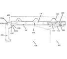
図1は、処置台への装着のための、本発明による放射線防護設備100の実施形態を示す。図1に示された例では、2枚の薄板101の各々が対応の締結装置102に配設されている。放射線防護設備100はさらにホルダを包含し、そしてこのホルダは長手形材105を有する。長手形材105は短尺および長尺側部を有する。長手形材105の短尺側部に側方から、旋回軸線115bを中心として旋回可能にハンドル103がホルダ115に取り付けられている。この実施形態によれば、ホルダ115は対応の接続要素115′により長手形材105に接続される。長手形材105はさらに接触面106を包含する。支持レール200(図5参照)に装着される時に、放射線防護設備100は、支持レール200の上方側で長手形材105の接触面106に部分的に支えられる。さらに、処置台に面する側において、長手形材105は、装着状態では支持レール200の対応のピン201(図5参照)が延在する一つ以上のV字形凹部110を有する。ゆえに、放射線防護設備100が支持レール200および/または処置台に沿って側方方向に偶発的に変位されることが防止されうる。さらに、ホルダは、垂直方向に均等に離間している孔が設けられている支持体116を包含する。同一の直径の孔は、長手形材105にも同じく見られる。放射線防護設備100の装着状態では、これらの孔を通して、上向きに延在する薄板118(図5参照)を付加的に装着することが可能である。これは、技術担当者の上半身のエリアでの放射線防護を保証する。図5参照。
FIG. 1 shows an embodiment of a
図1は、支持レール200への装着の準備が整った非係止つまり開放状態での放射線防護設備100を示す。開放状態では、係止ボルト104は支持レール200の方向に支持体116よりも突出しないか、突出してもごくわずかな程度のみである。このようにして、支持体116と、処置台に面する長手形材105の内側側部との間に支持レール200が配置されるように、放射線防護設備100が支持レール200に装着されうる。ハンドル103は非係止状態で上に回され、第1位置である開放位置の方向にホルダの長手形材の長尺側部に対して角度を成した位置になる。この角度は好ましくは10°から70°、とりわけ好ましくは30°である。結果的に、放射線防護設備100を運搬する時に、技術担当者の手首には可能な限り小さい負荷が印加され、最適な運搬簡易性を保証することが可能である。
FIG. 1 shows the
図1に示されているように、ハンドル103は、収容部107に延在する接続ロッド111との動作接続状態にある。ホルダ115のハンドル103は、回転軸線115bを中心として第2位置まで下向きに旋回する。
As shown in FIG. 1, the
ハンドル103がホルダ115′の回転軸線115bと接続される側部において、ハンドル103の正面はカム115aとして形成される。長手形材の長手方向で、カム115aはバネ113に反して接続ロッド111を内向きに押圧する。バネは、非係止状態のハンドル103が第1位置に保持されて偶発的に回転しないことを保証する。加えて、係止ボルト104との接続状態にあるスライダ112が、接続ロッド111に締結されている。係止ボルト104は平行四辺形で特定の高さの基部を有するため、係止ボルト104の基部は長尺側部と短尺側部とを有する。長尺側部は支持体116に対して45°の角度変位されている。係止ボルト104は、舌部・溝部接続によって収容部に摺動可能に設けられる。係止ボルト104の高さは、係止ボルトが収容部107の表面と同一平面ではないような寸法を持つ。そのため、係止ボルト104に対応する凹部を同じく45°の角度で有するスライダ112が係止ボルトとの動作接続状態になることが可能である。動作接続は、接続ロッド111が移動される時に、スライダ112が舌部・溝部接続状態の係止ボルト104を長手形材について外向きに押圧するように設計される。接続ロッド111の移動は、カム115aとして形成されたハンドル103の端部を旋回させることにより行われる。ゆえに、ハンドル103の旋回運動が係止ボルト104の移動と、ついには支持レール200での放射線防護設備100の係止とをもたらす係止機構が提供される。支持体116と収容部107とは、放射線防護設備100が支持レール200に装着される時に、係止状態にある係止ボルト104が支持レール200の底部に部分的または完全に延在するような寸法を持つ。係止ボルト104から支持レール200の底部までの距離は、好ましくは0から1mm、さらに好ましくは0.5mmである。放射線防護設備100が偶発的に支持レール200から離脱しないように、放射線防護設備100が支持レール200に係止される。
On the side where the
ハンドル103はさらに、その自由端部に、つまりハンドルがホルダ115に旋回可能に装着される端部と反対に設けられる摺動防止装置109を包含する。ハンドル103はさらに、ラッチ凹部を包含する。図1では、一つのラッチ凹部108のみが示されている。ラッチ凹部がホルダ115のエッジと接触している位置にハンドル103がある時に、一定の抵抗を超えることにより、つまり一定の旋回力を超えることによって初めてこの位置が解除されうるように、ハンドルがこの位置に固定される。
The
図2は、本発明による好適な第一実施形態の放射線防護設備100の一区分の斜視部分図を示す。特に、接続ロッド111と、接続ロッド111に装着されたスライダ112と、スライダ112との連通状態にあるとともに舌部・溝部機構により収容部107に装着される係止ボルト104と、支持体116とを示している。さらに、接続ロッド111との動作接続状態にあるハンドル103を、スライダ112への適当な圧力により開放位置つまり第1位置に保持するのに適した戻しバネ113を示している。
FIG. 2 shows a perspective partial view of a section of the
図3および4は、本発明による放射線防護設備の好適な第一実施形態の斜視図を示す。図1および図2と対照的に、接続ロッド111とバネ113と収容部107とスライダ112の上に、また係止ボルト104の一部の上に、保護カバー117が設けられている。係止ボルト104が側方方向に自由に移動して保護カバー118から突出できるように、対応の凹部が保護カバー117に設けられる。図3および4では、図1および2と対照的に、放射線防護設備100は係止状態にある。係止ボルト104は、支持体116を超えて支持レール200および/または処置台(ともに不図示)の方向に支持体116よりも突出している。放射線防護設備100が、支持レール200に装着されたこの状態にある時には、係止ボルト104が支持レール200の底部よりも部分的または完全に延出するように係止ボルト104を配設することが、このハンドル103の第2閉鎖位置で可能である。これにより放射線防護設備が係止され、偶発的な落下が防止される。ハンドル103の第2閉鎖位置は、長手形材105の長手方向について約−90°の角度で下を向いている。ハンドル103がホルダ115の一つの側部と同一平面になるように、ハンドル103はホルダ115の対応の凹部に設置される。しかし、本発明によれば、この閉鎖位置で、ハンドル103がホルダの対応凹部に設置されてホルダの底部と同一平面となるように、ハンドルがさらにホルダへ旋回されることも可能である。
3 and 4 show perspective views of a first preferred embodiment of a radiation protection installation according to the invention. In contrast to FIGS. 1 and 2, a
図4に示された実施形態で、接続ロッド111は、ハンドル103の非係止状態で固定リング111bが接続ロッド111の装着点を接続要素115′に形成するように接続ロッド111の端部から短い距離に配設される固定リング111bを包含する。さらに、カム115aとの接触状態にある端部では、接続ロッド111は端部区分111aを有する。接続ロッドの端部区分111aは好ましくは球形ヘッドとして形成され、好ましくは自己潤滑性および/または摺動材料で構成される。適当な材料は、真鍮またはテフロン(PTFE)などである。
In the embodiment shown in FIG. 4, the connecting
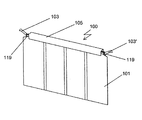
図5は、本発明の第二実施形態による、処置台の側方区分およびヘッド区分の支持レール200で係止状態にある二つの放射線防護設備100のセットを示す。この第二実施形態では、長手形材の短尺側部と長尺側部の両方に二つのハンドル103,103′を備える放射線防護設備100が設けられている。この場合に、ハンドル103と第1ハンドル103′とは、上で図1から4において説明された好適な第一実施形態による係止機構との連通状態にある。ゆえに、各放射線防護設備100は、少なくとも一つの係止ボルトと二つのハンドルと二つのホルダとを包含する。
FIG. 5 shows a set of two
本発明によれば、支持レール200は処置台のすべての長尺および短尺側部に、ゆえに処置台の尾端部にも装着されうる。さらに、支持レール200は、処置台の一つ以上の側部で中断されるか、複数の支持レール200が処置台の一つ以上の同じ側部に装着されうる。本発明によれば、相互に隣接する複数の放射線防護設備100を処置台の一つ以上の同じ側部に装着すること、例えば、相互に隣接する二つの放射線防護設備100を処置台の長手側部に装着することが可能である。
According to the present invention, the
図のように、技術担当者の上半身を放射から防護するため、第1着脱式薄板118aと第2着脱式薄板118b(一つが図示)とを付加的に設けることが可能である。第1着脱式薄板118aは、処置台の長尺側部に配設され、処置台に向かう方向に屈曲部を有し、二部形状で設計される。第2着脱式薄板118bは幅広であり、直線的な基本形状を有する。これは処置台の短尺側部に配設される。第1着脱式薄板118aと第2着脱式薄板118bとは、着脱式薄板118a,118bの下端部分が薄板101の上端区分と重複状態で整列される時に薄板101の両端区分が覆われるように好ましくは装着され、また好ましくはそのような寸法を有する。着脱式薄板118a,118bは、ホルダの上方側の孔114へ挿入されるのに適した一つ以上のピン(不図示)をその底部に有する。着脱式薄板118a,118bは、ホルダおよび/または長手形材105に別の方式で、好ましくは以下でさらに説明されるU字形保持手段によって取り付けられうる。
As shown, a first detachable
孔114は、例えば交互に異なる距離を有する。しかし、別の実施形態によれば、等しい距離を有してもよい。ゆえに、孔114は、放射線防護設備100、または相互に隣接して配設される放射線防護設備100に孔列を形成するため、着脱式薄板118a,118bが孔列に様々に配設されうる。そのため、例えば、患者が処置されるための間隙が二つの着脱式薄板118a,118bの間に形成されるように、外科処置中に着脱式薄板118a,118bを変位させることが可能である。処置後に、変位された着脱式薄板118a,118bを最初の位置へ戻すことにより、この間隙が再び閉じられうる。
The
本発明によれば、着脱式薄板118a,118bを配設および保持するための他の手段により孔の列114を置き換えることも可能である。例えば、形状係止および/または力係止方式でホルダに締結されうる締結装置を、各着脱式薄板118a,118bが包含しうる。例えば、締結装置は、長手形材105に装着可能であるU字形材を有する。好ましくは、U字形材はブラケットのように形成され、例えば長手形材105の外側にあるラッチ溝部との嵌合状態に解除可能に置かれうるラッチ手段を包含する。ここで、少なくとも一つのラッチ溝部または凸部または凹部がプラスチックなどの弾性材料で構成されると有利である。
According to the present invention, it is also possible to replace the row of
支持レール200での放射線防護設備100の長手方向の変移を防止することが可能であるように、支持レール200のボルト201は放射線防護設備100のV字形凹部110に突出する。
The
さらなる実施形態で、放射線防護設備100は二つの旋回可能ハンドル103,103′を包含する。しかし、ハンドル103のみが係止機構との動作接続状態にある。他のハンドル103′はホルダ115′に旋回可能に取り付けられるに過ぎず、第1および第2位置へ適宜旋回されうるが、こうすることで係止機構を操作するわけではない。
In a further embodiment, the
上述した係止による支持レール200への放射線防護設備100の様々な装着を使用することと、放射線防護設備のホルダへの着脱式薄板118a,118bの様々な配設の使用とにより、手術および/または技術担当者が放射線から完全に防護されるのと同時に、手術および/または技術担当者のニーズ、および/または個々の患者治療の特定の状況に放射線防護が適応化される。
By using various attachments of the
図6aおよび6bは、本発明の好適な第三実施形態による放射線防護設備の斜視図を示す。図の例では、放射線防護設備100は4枚の薄板101を包含し、各々が対応の締結装置に装着される。放射線防護設備100はさらにホルダを包含し、そしてこのホルダは長手形材105を包含する。長手形材105の両側では、ハンドル103,103′が短尺側部に側方から旋回可能に取り付けられる。さらに、放射線防護設備100は、長手形材105の長尺側部に対して平行に支持体116(不図示)に装着される横断薄板119を包含する。この実施形態で、薄板101は上端部の区分に三角形を有し、これは締結装置の方向に三角形を成すようにテーパ状である。横断薄板119は、処置台の方向に薄板101の上部を覆うように装着および設計される。好ましくは、薄板101の上部が締結装置に接続されるゾーンを横断薄板119が覆う。図6a,6bに示されている例では、長手形材105は孔14を有していない。
Figures 6a and 6b show perspective views of radiation protection equipment according to a third preferred embodiment of the invention. In the illustrated example, the
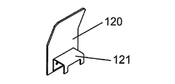
図7aは、本発明の別の好適な実施形態による着脱式薄板120を示す。U字形輪郭を有する保持手段121が着脱式薄板120に装着され、保持手段は好ましくはプラスチックで構成される。このU字形保持手段121によって、着脱式薄板120は形状係止および/または力係止方式で放射線防護設備100に装着されうる。この例では、処置台に面する側部でU字形輪郭を備える保持手段から凹部が切除されるため、この側部では2本のバーのみが見られる。安定的な保持手段が保証されるように、これら2本のバーは処置台に面する長手形材105の側部に達している。長手形材では、着脱式薄板120が長手方向に摺動変位されうる。
FIG. 7a shows a
図7bは、本発明の別の好適な実施形態による着脱式薄板120を示す。図7aの着脱式薄板と比較すると、図7bに示された例の着脱式薄板は、例を挙げると3倍だけ長手方向に幅広である。したがって、図7bに示された例の保持手段121も長手方向に長くなっている。処置台に面する側部では、3本のバーが形成されるように保持手段121は二つの凹部を有する。長手形材105への着脱式薄板の確実な嵌着の保証を可能にするように、これら3本のバーは、処置台の方向を向く側で長手形材105をクランプする。本発明によれば、保持手段121は、1本のみまたは3本以上のバーも有しうる。ゆえに、バーの数および/または幅は、保持手段121の所望のクランプ力に応じて選択および/または変更されうる。
FIG. 7b shows a
図7bに示された実施形態でも、放射線防護設備100の長手形材105上で、着脱式薄板が長手方向に摺動変位されうる。
In the embodiment shown in FIG. 7 b, the detachable thin plate can be slid in the longitudinal direction on the
図と対応の説明に基づいて発明が詳細に図示および説明されたが、この図およびこの詳細な説明は、図解および例示であって発明を制限するものと理解されるべきではない。当業者が以下の請求項の範囲および趣旨を離脱することなく変更および変形を行ってもよいことは明白である。特に、本発明は、様々な実施形態について以上または以下に言及されるか示された特徴のいかなる組み合わせをも含む実施形態も含む。 While the invention has been illustrated and described in detail based on the drawings and the corresponding description, the drawings and this detailed description are illustrative and exemplary and are not to be construed as limiting the invention. It will be apparent to those skilled in the art that changes and modifications may be made without departing from the scope and spirit of the following claims. In particular, the invention includes embodiments that include any combination of features mentioned or shown above or below for the various embodiments.
本発明は、他の特徴に関してここに示される、および/または以上または以下に言及されていなくても、図の個々の特徴も含む。さらに、図および説明に記された実施形態の代替例とともに個々の代替例は、発明の主題および/または開示による主題から除外されうる。開示は、請求項および/または実施形態に記された特徴を排他的に包含する実施形態とともに、他の付加的な特徴を包含する実施形態も含む。 The invention also includes the individual features of the figures shown here with respect to other features and / or not mentioned above or below. Further, individual alternatives as well as alternatives to the embodiments described in the figures and description may be excluded from the subject matter of the invention and / or subject matter disclosed. The disclosure includes embodiments that exclusively include the features recited in the claims and / or embodiments, as well as embodiments that include other additional features.
100 放射線防護設備
101 薄板
102 締結装置
103,103′ ハンドル
104 係止ボルト
105 長手形材
106 接触面
107 収容部
109 摺動防止装置
110 V字形凹部
111 接続ロッド
111a 端部
111b 固定リング
112 スライダ
113 戻しバネ
114 孔
115 ホルダ
115a カム
115b 回転軸線
115′ 接続要素
116 支持体
117 保護カバー
118a 第1着脱式薄板
118b 第2着脱式薄板
119 横断薄板
120 着脱式薄板
121 保持手段
200 支持レール
201 ピン
DESCRIPTION OF
Claims (23)
放射線からの防護のための材料を包含するとともに旋回可能に取り付けられる少なくとも一つの薄板における締結装置であって、前記支持レールに装着されうるホルダを包含する締結装置であり、前記ホルダが、
旋回可能に取り付けられる少なくとも一つのハンドルであって、自由端部と、ハンドルが旋回可能に取り付けられる端部とを有する少なくとも一つのハンドルを包含する、締結装置と、
前記ホルダを前記支持レールに係止するのに適した係止機構であって、前記ホルダに旋回可能に取り付けられる少なくとも一つのハンドルの旋回動作により作動可能である係止機構と、
長手形材であって、短尺側部および長尺側部を有する長手形材と、を備え、
前記ハンドルは、前記長手形材の前記短尺側部に装着され、前記ホルダの前記長手形材の前記長尺側部に対して平行な面内で往復して旋回されるのに適している、放射線防護設備。 For attachment to the least one support rail, a radiation protection equipment to be attached to one or more sides of the processing table,
A fastening apparatus in at least one thin plate mounted for swivel in together and including the material for the protection of radiation or al a fastening device comprising a holder which can be mounted on the support rail, the holder But,
A fastening device including at least one handle pivotally mounted, the handle having at least one free end and an end to which the handle is pivotally mounted;
A locking mechanism suitable for locking the holder to the support rail, the locking mechanism being operable by a pivoting motion of at least one handle pivotably attached to the holder;
A longitudinal profile having a short side and a long side , and
The handle is attached to the short side portion of the longitudinal profile and is suitable for reciprocating in a plane parallel to the long side of the longitudinal profile of the holder. Radiation protection equipment.
Applications Claiming Priority (3)
| Application Number | Priority Date | Filing Date | Title |
|---|---|---|---|
| DE102012218391.4 | 2012-10-09 | ||
| DE102012218391.4A DE102012218391A1 (en) | 2012-10-09 | 2012-10-09 | Radiation protection order |
| PCT/EP2013/070977 WO2014056940A2 (en) | 2012-10-09 | 2013-10-08 | Radiation protection arrangement |
Publications (3)
| Publication Number | Publication Date |
|---|---|
| JP2015533569A JP2015533569A (en) | 2015-11-26 |
| JP2015533569A5 JP2015533569A5 (en) | 2016-11-10 |
| JP6293764B2 true JP6293764B2 (en) | 2018-03-14 |
Family
ID=49551579
Family Applications (1)
| Application Number | Title | Priority Date | Filing Date |
|---|---|---|---|
| JP2015536103A Active JP6293764B2 (en) | 2012-10-09 | 2013-10-08 | Radiation protection equipment |
Country Status (6)
| Country | Link |
|---|---|
| US (1) | US9451922B2 (en) |
| EP (1) | EP2906122B1 (en) |
| JP (1) | JP6293764B2 (en) |
| CN (1) | CN104736063B (en) |
| DE (1) | DE102012218391A1 (en) |
| WO (1) | WO2014056940A2 (en) |
Families Citing this family (14)
| Publication number | Priority date | Publication date | Assignee | Title |
|---|---|---|---|---|
| PL2930719T3 (en) * | 2014-04-10 | 2018-11-30 | Mettler-Toledo Safeline X-Ray Limited | X-ray system |
| JP6444112B2 (en) * | 2014-09-25 | 2018-12-26 | 株式会社Ina医療開発研究所 | Radiation protection device and radiation protection system equipped with radiation protection device |
| EP4241750A3 (en) | 2014-12-05 | 2023-12-20 | Egg Medical, Inc. | A multimodality medical procedure mattress-based device |
| DE102015208829B4 (en) | 2015-05-12 | 2020-08-27 | Mavig Gmbh | Radiation protection order |
| WO2017218871A1 (en) * | 2016-06-17 | 2017-12-21 | Plasticraftsmen Llc | Radiation shield for x-ray examination table |
| FR3060191B1 (en) * | 2016-12-14 | 2020-06-12 | Lemer Protection Anti-X Par Abreviation Societe Lemer Pax | MOBILE RADIATION PROTECTION SCREEN |
| US10056162B1 (en) | 2017-02-08 | 2018-08-21 | Global Imaging Solutions Company | X-ray shielding system for use with an X-ray producing gantry |
| US10004466B1 (en) | 2017-02-08 | 2018-06-26 | Global Imaging Solutions Company | X-ray shielding system |
| US10265037B2 (en) | 2017-02-08 | 2019-04-23 | Global Imaging Solutions Company | X-ray shielding system |
| US9877688B1 (en) | 2017-02-08 | 2018-01-30 | Global Imaging Solutions Company | X-ray shielding system for use with an x-ray producing gantry |
| US9867583B1 (en) * | 2017-02-08 | 2018-01-16 | Global Imaging Solutions Company | X-ray shielding system |
| EP3664715A2 (en) * | 2017-08-11 | 2020-06-17 | Intervention for Life, LLC | Radiation shielding system |
| WO2020107017A1 (en) * | 2018-11-23 | 2020-05-28 | Eco Cath-Lab Systems, Inc. | Radiation shield |
| US11786189B2 (en) * | 2021-11-21 | 2023-10-17 | Shimadzu Corporation | Proximity operation-type X-ray fluoroscopic imaging apparatus |
Family Cites Families (14)
| Publication number | Priority date | Publication date | Assignee | Title |
|---|---|---|---|---|
| DE1466848A1 (en) | 1964-03-14 | 1969-02-20 | Koch & Sterzel Kg | Secondary radiation protection device on X-ray examination devices |
| DE1516420A1 (en) | 1966-03-19 | 1969-08-07 | Siemens Ag | Radiation protection device for X-ray examination devices |
| US4062518A (en) | 1976-11-10 | 1977-12-13 | General Electric Company | X-ray shielding device |
| DE3012463A1 (en) | 1980-03-31 | 1981-10-08 | Siemens AG, 1000 Berlin und 8000 München | Target X=ray appts. with radiation protection - has guide rail for each protection device on appts. lower and side edges, and has specified protection sheet carrier |
| DE3326880A1 (en) * | 1983-07-26 | 1985-02-07 | Knut Dr. 7802 Merzhausen Korth | Protective device |
| US5006718A (en) * | 1989-07-21 | 1991-04-09 | Lenhart Mark J | X-ray shield for X-ray examination table |
| DE29704613U1 (en) | 1996-03-26 | 1997-06-05 | Siemens Ag | Radiation protection device for an X-ray diagnostic device |
| JP2001120543A (en) * | 1999-10-28 | 2001-05-08 | Fukuyama Kenkosha:Kk | X-ray protective panel for medical examination table |
| SE516433C2 (en) * | 2000-05-02 | 2002-01-15 | Ove Bornvall Med Borntech Fa | Methods and devices for protection against radiation when working in a radiant zone |
| DE10325567B4 (en) * | 2003-06-05 | 2008-03-13 | Mavig Gmbh | Radiation protection arrangement with separable enclosure |
| DE102009025380A1 (en) * | 2009-06-18 | 2010-12-23 | Mavig Gmbh | Radiation protection order |
| DE102009053619B3 (en) * | 2009-11-17 | 2011-07-28 | MAVIG GmbH, 81829 | Radiation-fin arrangement |
| DE102009057366B4 (en) * | 2009-12-08 | 2020-11-12 | Mavig Gmbh | Radiation protection device |
| US20140029720A1 (en) * | 2012-07-30 | 2014-01-30 | Azriel Binyamin Osherov | Movable shield for reducing radiation exposure of medical personnel |
-
2012
- 2012-10-09 DE DE102012218391.4A patent/DE102012218391A1/en not_active Withdrawn
-
2013
- 2013-10-08 JP JP2015536103A patent/JP6293764B2/en active Active
- 2013-10-08 US US14/434,448 patent/US9451922B2/en active Active
- 2013-10-08 EP EP13786632.3A patent/EP2906122B1/en active Active
- 2013-10-08 CN CN201380052919.9A patent/CN104736063B/en active Active
- 2013-10-08 WO PCT/EP2013/070977 patent/WO2014056940A2/en active Application Filing
Also Published As
| Publication number | Publication date |
|---|---|
| US9451922B2 (en) | 2016-09-27 |
| EP2906122A2 (en) | 2015-08-19 |
| WO2014056940A2 (en) | 2014-04-17 |
| CN104736063B (en) | 2017-07-28 |
| WO2014056940A3 (en) | 2014-07-31 |
| CN104736063A (en) | 2015-06-24 |
| JP2015533569A (en) | 2015-11-26 |
| US20150272519A1 (en) | 2015-10-01 |
| EP2906122B1 (en) | 2016-12-21 |
| DE102012218391A1 (en) | 2014-04-10 |
Similar Documents
| Publication | Publication Date | Title |
|---|---|---|
| JP6293764B2 (en) | Radiation protection equipment | |
| JP6269505B2 (en) | Shelf holder | |
| JP6735740B2 (en) | Organizer for surgical instruments and items used during surgery | |
| US20240082480A1 (en) | Sterile transfer of fluid | |
| US7857271B2 (en) | Surgical tool holder with engagement portions | |
| US8517233B2 (en) | Assistant surgical device | |
| TWI533900B (en) | Medical device clamps, medical device pole clamps and rapid attach and release clamps | |
| US10952805B2 (en) | Medical tray assembly | |
| EP3046475B1 (en) | Lock-block shield device | |
| US20150144746A1 (en) | Medical Line Organizer | |
| EP1495724B1 (en) | Surgical retractors | |
| US9953731B2 (en) | Radiation protection arrangement | |
| US11760400B2 (en) | Apparatus for suspending radio-opaque curtains | |
| US8485567B1 (en) | Sterilization cassette | |
| WO2016160581A1 (en) | Retractable device | |
| US20150204699A1 (en) | Clip for a Patient Monitoring Pod | |
| US20180263436A1 (en) | Wearable Sterile Alcohol Pad Dispensing Device | |
| ES2933133T3 (en) | Holding system to make available a container containing cleaning or disinfection wipes or disposable gloves | |
| JP2005317641A (en) | Apparatus unit removable structure and electronic apparatus | |
| CN108368995B (en) | Lighting device with detachable handle | |
| WO2014012064A2 (en) | Clip for a patient monitoring pod | |
| WO2014183060A2 (en) | Clamp for immobilizing a medical scope | |
| RU2753317C2 (en) | Clamping device | |
| CN109952072B (en) | Protective cover for a component of a medical device | |
| US20140275802A1 (en) | Surgical retractor support system |
Legal Events
| Date | Code | Title | Description |
|---|---|---|---|
| A521 | Request for written amendment filed |
Free format text: JAPANESE INTERMEDIATE CODE: A523 Effective date: 20160915 |
|
| A621 | Written request for application examination |
Free format text: JAPANESE INTERMEDIATE CODE: A621 Effective date: 20160915 |
|
| A977 | Report on retrieval |
Free format text: JAPANESE INTERMEDIATE CODE: A971007 Effective date: 20170816 |
|
| A131 | Notification of reasons for refusal |
Free format text: JAPANESE INTERMEDIATE CODE: A131 Effective date: 20170822 |
|
| A521 | Request for written amendment filed |
Free format text: JAPANESE INTERMEDIATE CODE: A523 Effective date: 20171122 |
|
| TRDD | Decision of grant or rejection written | ||
| A01 | Written decision to grant a patent or to grant a registration (utility model) |
Free format text: JAPANESE INTERMEDIATE CODE: A01 Effective date: 20180123 |
|
| A61 | First payment of annual fees (during grant procedure) |
Free format text: JAPANESE INTERMEDIATE CODE: A61 Effective date: 20180214 |
|
| R150 | Certificate of patent or registration of utility model |
Ref document number: 6293764 Country of ref document: JP Free format text: JAPANESE INTERMEDIATE CODE: R150 |
|
| R250 | Receipt of annual fees |
Free format text: JAPANESE INTERMEDIATE CODE: R250 |
|
| R250 | Receipt of annual fees |
Free format text: JAPANESE INTERMEDIATE CODE: R250 |
|
| R250 | Receipt of annual fees |
Free format text: JAPANESE INTERMEDIATE CODE: R250 |
|
| R250 | Receipt of annual fees |
Free format text: JAPANESE INTERMEDIATE CODE: R250 |