JP6290686B2 - Chamber apparatus and processing system - Google Patents
Chamber apparatus and processing system Download PDFInfo
- Publication number
- JP6290686B2 JP6290686B2 JP2014073561A JP2014073561A JP6290686B2 JP 6290686 B2 JP6290686 B2 JP 6290686B2 JP 2014073561 A JP2014073561 A JP 2014073561A JP 2014073561 A JP2014073561 A JP 2014073561A JP 6290686 B2 JP6290686 B2 JP 6290686B2
- Authority
- JP
- Japan
- Prior art keywords
- door
- chamber
- opening
- chamber body
- guide
- Prior art date
- Legal status (The legal status is an assumption and is not a legal conclusion. Google has not performed a legal analysis and makes no representation as to the accuracy of the status listed.)
- Active
Links
Images


Description
本発明はチャンバ装置及び処理システムに関する。 The present invention relates to a chamber apparatus and a processing system.
半導体の製造設備等においては、ウエハ等のワークは、内部が真空に維持されたチャンバ装置を経由して処理装置に対して出し入れされる。内部のメンテナンスを可能とするため、チャンバ本体の上部に開閉可能な扉を備えたチャンバ装置が提案されている。特許文献1には、片開き式の扉を備えたチャンバ装置が開示されており、扉を上下方向に回動することでチャンバ装置内が開閉される。
In a semiconductor manufacturing facility or the like, a workpiece such as a wafer is taken in and out of a processing apparatus via a chamber apparatus whose inside is maintained in a vacuum. In order to allow internal maintenance, a chamber apparatus having a door that can be opened and closed at the top of the chamber body has been proposed.
ワークが大型化すると、チャンバ装置も大型化し、扉も大型化する傾向にある。片開き式の扉の場合、チャンバ装置の上方に扉を開放するための大きなスペースが必要となる。チャンバ装置が設置される設備環境によっては、その上方に扉の開放のための十分なスペースを確保できない場合がある。また、扉が大型化するとその重量も重くなることから、扉の回動が人力では困難な場合もあり、扉を開閉するために巻き上げ機や吊上げ機などの設備が必要となる。一方、チャンバ装置内の気密性を維持するため、扉の閉鎖時にはチャンバ本体に対して扉を押し付ける仕組みも必要となる。 As the workpiece becomes larger, the chamber device also becomes larger and the door tends to become larger. In the case of a single-open door, a large space for opening the door is required above the chamber device. Depending on the facility environment in which the chamber apparatus is installed, there may be a case where a sufficient space for opening the door cannot be secured above the chamber environment. Further, since the weight of the door increases as the door becomes larger, it may be difficult to rotate the door by human power, and facilities such as a hoisting machine and a lifting machine are required to open and close the door. On the other hand, in order to maintain the airtightness in the chamber apparatus, a mechanism for pressing the door against the chamber body when the door is closed is also required.
本発明の目的は、チャンバ装置上方に扉の開放のためのスペースを必要とせず、扉の開閉に補助動力を必要とせず、しかも扉閉鎖時におけるチャンバ装置内の気密性を維持可能とすることにある。 An object of the present invention is that no space for opening the door is required above the chamber device, no auxiliary power is required for opening and closing the door, and airtightness in the chamber device can be maintained when the door is closed. It is in.
本発明によれば、上面に開口部を備えるチャンバ本体と、前記開口部を開閉する扉と、前記チャンバ本体に設けられ、前記開口部に位置する前記扉を前記チャンバ本体側に押圧する押圧機構と、前記チャンバ本体に対して前記扉をスライド可能に支持するガイド機構と、を備え、前記扉は、前記開口部を覆う部分を含み、前記押圧機構に押圧される扉本体と、前記ガイド機構にスライド可能に支持されると共に、前記扉本体を前記チャンバ本体における前記上面から離間する方向に付勢する支持機構と、を備え、前記支持機構は、前記扉本体を支持する第1の部材と、前記ガイド機構に対してスライドされる第2の部材と、前記第1の部材と前記第2の部材との間に介在される弾性部材と、を備える、ことを特徴とするチャンバ装置が提供される。 According to the present invention, a chamber main body having an opening on the upper surface, a door that opens and closes the opening, and a pressing mechanism that is provided in the chamber main body and presses the door located at the opening toward the chamber main body. And a guide mechanism that slidably supports the door with respect to the chamber body, the door including a portion that covers the opening, the door body being pressed by the pressing mechanism, and the guide mechanism while being slidably supported, e Bei and a support mechanism for urging in a direction away from said upper surface in said chamber body and the door body, wherein the support mechanism includes a first member supporting the door body And a second member that is slid with respect to the guide mechanism, and an elastic member that is interposed between the first member and the second member. Provided That.
また、本発明によれば、チャンバ装置と、基板を処理する処理装置と、を備え、前記チャンバ装置は、上面に開口部を備えるチャンバ本体と、前記開口部を開閉する扉と、前記チャンバ本体に設けられ、前記開口部に位置する前記扉を前記チャンバ本体側に押圧する押圧機構と、前記チャンバ本体に対して前記扉をスライド可能に支持するガイド機構と、を備え、前記扉は、前記開口部を覆う部分を含み、前記押圧機構に押圧される扉本体と、前記ガイド機構にスライド可能に支持されると共に、前記扉本体を前記チャンバ本体における前記上面から離間する方向に付勢する支持機構と、を備え、前記処理装置は、前記チャンバ装置の前記扉のスライド方向側に配置され、かつ、開放された前記扉と対向する位置に配設されたスロット部と、前記スロット部と連通して前記扉を収容する収容部と、を備える、ことを特徴とする処理システムが提供される。 Further, according to the present invention includes a switch Yanba apparatus, a processing apparatus for processing a substrate, wherein the chamber device comprises a chamber body comprising an opening in the top surface, a door for opening and closing the opening, the chamber A pressing mechanism that is provided in a main body and presses the door located at the opening portion toward the chamber main body; and a guide mechanism that slidably supports the door with respect to the chamber main body. A door body that includes a portion that covers the opening, is slidably supported by the guide mechanism, and is slidably supported by the guide mechanism, and urges the door body in a direction away from the upper surface of the chamber body. comprising a support mechanism, wherein the processing unit includes: the arranged in the sliding direction side of the door of the chamber apparatus, and arranged to open said door position opposed to the slot unit, Communicates with the serial slot portion and a storage portion for storing the door, is provided a processing system, characterized in that.
本発明によれば、チャンバ装置上方に扉の開放のためのスペースを必要とせず、扉の開閉に補助動力を必要とせず、しかも扉閉鎖時におけるチャンバ装置内の気密性を維持することができる。 According to the present invention, no space for opening the door is required above the chamber device, no auxiliary power is required to open and close the door, and the airtightness in the chamber device can be maintained when the door is closed. .
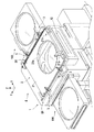
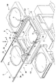
図1及び図2は本発明の一実施形態に係るチャンバ装置Aの使用例を示す斜視図であり、図1は扉2を全閉にした態様を示し、図2は扉2を全開にした態様を示す。本実施形態のチャンバ装置Aは、基板(ウエハ)を搬送するロボット30を収容する真空搬送装置の外壁を構成するものであるが、本発明のチャンバ装置は各種用途のチャンバ装置に適用可能である。なお、各図において、矢印Zは上下方向を示し、矢印X及びYは互いに直交する水平方向を示す。
1 and 2 are perspective views showing an example of use of a chamber apparatus A according to an embodiment of the present invention. FIG. 1 shows a state in which the
本実施形態のチャンバ装置Aは、チャンバ本体1と扉2とを備える。図2に示すようにチャンバ本体1は、上面に開口部11が形成された箱型の中空体であり、開口部11は扉2により開閉される。チャンバ本体1には、不図示のバキュームポンプが接続され、扉2の全閉時においては、その内部空間を真空状態に維持可能な気密性を有している。
The chamber apparatus A of this embodiment includes a
チャンバ本体1のX方向の両側部には、ロードロックチャンバ100、100が接続されている。ロードロックチャンバ100はゲートバルブを備え、ゲートバルブを開閉することで、チャンバ装置Aとロードロックチャンバ100との間で、ロボット30による基板の出し入れが可能となる。ロボット30は例えば水平多関節型のロボットである。
チャンバ本体1のY方向の一方側部には、プロセスチャンバ(不図示)に接続される開口部12が形成されている。この開口部12を介して、チャンバ装置Aとプロセスチャンバとの間で、ロボット30による基板の出し入れが可能となる。
An
扉2は、方形板状の扉本体21と、扉本体21を支持する支持機構22とを備える。支持機構22の詳細は図3及び図4(A)及び(B)を参照して後述する。
The
扉本体21は開口部11を覆う部分を含み、その中央部には、例えば、透明部材で閉鎖された窓部21aを有している。扉2の全閉時においても窓部21aを通してチャンバ内部を視認することが可能となっている。扉2のX方向の両側部において扉2とチャンバ本体1との間には、スライドレールSRが設けられており、扉2は図1の全閉位置と図2の全開位置との間で、Y方向にスライド自在となっている。扉本体21には扉2を開閉する際に作業者が把持可能なハンドル21b、21bが設けられている。
The door
チャンバ本体1には、全閉位置において扉2をチャンバ本体1側に押圧する押圧機構3が設けられている。本実施形態の場合、押圧機構3は、扉2のX方向両側の各辺に沿って2つずつ、合計で4つ配置されている。
The
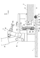
図3及び図4(A)及び(B)を参照してスライドレールSR、支持機構22及び押圧機構3の構成を説明する。
The configuration of the slide rail SR, the
スライドレールSRは、本実施形態の場合、2段階で伸縮するスライドレールを例に挙げて説明する。スライドレールSRは、チャンバ本体1側の構成として、ガイドレール(アウタレール)151と、ベアリングユニットBUとを備え、これらはチャンバ本体1に対して扉2をスライド可能に支持するガイド機構を構成している。また、スライドレールSRは、扉2側の構成として可動レール(インナレール)24を備える。なお、スライドレールのスライド段階数は、扉2の大きさ、開口の度合いに応じて適宜選択されるものであり、1段階や3段階以上で伸縮するスライドレールであってもよい。
In the present embodiment, the slide rail SR will be described by taking a slide rail that expands and contracts in two steps as an example. The slide rail SR includes a guide rail (outer rail) 151 and a bearing unit BU as a configuration on the
ガイドレール151は、チャンバ本体1に固定されたレール部材であり、C字型の断面を有してY方向に延設されている。ベアリングユニットBUは、中間レール154と、外側転動体152と、保持器153と、内側転動体155と、保持器156とを備え、可動レール24をガイドレール151の延長方向(Y方向)に沿ってスライドさせる。
The
中間レール154は、Y方向に延びるレール部材であり、ガイドレール151と全長が略同じであり、ガイドレール151の内側に配置されている。外側転動体152はボールベアリングであり、Z方向に離間して2列設けられている。上列に位置する外側転動体152が上側のガイドレール151の内側に、下列に位置する外側転動体152が下側のガイドレール151の内側に摺動される。各列の外側転動体152はY方向に複数並べて配置された転動体群で構成されている。保持器153は各列の外側転動体152を一体に保持する。各列の外側転動体152は、ガイドレール151と中間レール154との間にそれぞれ配置されており、外側転動体152の転動により、中間レール154は円滑にY方向にスライド可能となっている。
The
内側転動体155はボールベアリングであり、外側転動体155の内側において、Z方向に離間して2列設けられている。上列に位置する内側転動体155が上側の中間レール154の内側に、下列に位置する内側転動体155が下側の中間レール154の内側に摺動される。各列の内側転動体155はY方向に複数並べて配置された転動体群で構成されている。保持器156は各列の内側転動体155を一体に保持する。各列の内側転動体155は、中間レール154と可動レール24との間にそれぞれ配置されており、内側転動体155の転動により、可動レール24は円滑にY方向にスライド可能となっている。
The inner
支持機構22は、上記のガイド機構(ガイドレール151、ベアリングユニットBU)にスライド可能に支持されると共に、扉本体21をチャンバ本体1における上面から離間する方向に付勢する機構である。
The
本実施形態の場合、支持機構22は、可動レール24と、支持体23と、弾性部材25と、支持体21cと、を備える。支持体23、弾性部材25及び支持体21cは、全閉位置を基準として、4つの押圧機構3の配設部位に対応した位置に設けられており、扉本体21のX方向両側の各辺に沿って2つずつ、合計で4つ配置されている。これらの各配設部位において、扉本体21には切欠き21dが形成されている。
In the case of this embodiment, the
支持体23は可動レール24に固定されたL字型の部材である。本実施の形態においては、Y方向に離間する2つの支持体23、23が、可動レール24に固定される。2つの支持体23と1つの可動レール24とは、一体となって、Y方向にスライドする部材を構成する。支持体23は、切欠き21d内においてZ方向に突出した円柱状の支持部23aを備える。支持部23aには弾性部材25が取り付けられている。弾性部材25は本実施形態の場合、コイルバネであり、その中心部に支持部23aが挿通されている。
The
支持体21bは、切欠き21dの上側を覆うように扉本体21に固定されており、弾性部材25の付勢力を受けて扉本体21を支持する部材を構成する。弾性部材25は、支持体23と支持体21cとの間に介在しており、支持体21cを介して扉本体21をチャンバ本体1の上面から離間する方向(Z方向上側)に常時付勢している。言い換えると、弾性部材25は、支持体21cを介して扉本体21をチャンバ本体1の上面から離間しうるように、その付勢力が調整されたものである。
The
以上の構成により、扉本体21は、可動レール24に対してZ方向に変位可能にフローティング支持されている。
With the above configuration, the
押圧機構3は、ハンドル31と、リンク機構32と、レバー33と、を備える。レバー33は、支持体21cに当接する当接部材33a(ここではボルト)を備えている。本実施形態の場合、押圧機構3はトグルクランプを構成しており、図4(A)の状態と図4(B)の状態の2つの状態で安定する。図4(A)及び(B)に示すようにハンドル31を下方に向けて回動すると、その回動方向に応じてリンク機構32によってレバー33が下方に向けて回動する。図4(A)は、当接部材33aが支持体21cから離間した退避状態を示しており、図4(B)は当接部材33aが支持体21cに当接して扉本体21をチャンバ本体1側に押圧するクランプ状態を示している。本実施形態では、ハンドル31を手動操作することにより押圧機構3を動作させる構成としているが、モータ等の駆動源を備えて押圧機構3が自動的に作動するように構成してもよい。
The
チャンバ本体1の上面には、開口部11を囲むように溝13が形成されており、この溝13にはシール部材(例えば、Oリング)14が保持されている。扉2の全閉時に、図4(B)に示すように押圧機構3をクランプ状態にすると、扉本体21が支持体21cを介して下方に押圧され、シール部材14を押しつぶすようにして降下する。これにより、開口部11の周りにおける扉2とチャンバ本体1との当接部がシール部材14によってシールされ、チャンバ装置Aの内部空間が気密に維持される。
A
一方、図4(A)に示すように押圧機構3を退避状態にすると、扉本体21に対する押圧が解除され、弾性部材25の付勢により扉本体21が上昇する。このとき、扉本体21はフローティング支持されている。このため、扉2における可動レール24と、中間レール154との間にはZ方向の負荷がほぼ作用しないので、扉2を全閉位置と全開位置との間で円滑にスライドすることができる。
On the other hand, as shown in FIG. 4A, when the
以上の構成からなるチャンバ装置Aの作用について、図1及び図2を参照して説明する。チャンバ装置A内を気密にする場合、図1に示すように扉2を全閉位置に位置させ、かつ、押圧機構3をクランプ状態とする。これにより、図4(B)に示した通り、扉本体21の下面とチャンバ本体1との間でシール部材14が圧縮され、開口部11を扉2で気密に塞ぐことができる。
The operation of the chamber apparatus A having the above configuration will be described with reference to FIGS. When making the inside of the chamber apparatus A airtight, as shown in FIG. 1, the
扉2を全開にする場合、まず、押圧機構3を退避状態にする。これにより、図4(A)に示した通り、弾性部材25の付勢で扉本体21が浮き上がった状態となる。作業者は、ハンドル21b、21bを把持して、扉2をY方向にスライドさせ、図2に示すように全開位置に移動させることができる。これにより、開口部11が開放されるので、チャンバ本体1の内部のメンテナンス等が可能となる。
When the
このように本実施形態のチャンバ装置Aは、扉2を水平にスライドさせるため、装置上方に扉の開放のためのスペースを必要としない。また、扉2はスライドさせる際、上下方向においてフローティング支持されているので、開閉時に要する力は極めて小さくて済む。よって、巻き上げ機や吊上げ機などの補助動力を要する設備を必要とせず、作業員のみで容易に開閉することができる。更に、押圧機構3によって、扉2の閉鎖時におけるチャンバ装置A内の気密性を維持することができる。
Thus, since the chamber apparatus A of this embodiment slides the
<他の実施形態>
<位置決め機構>
全閉位置と全開位置とでそれぞれ扉2の位置を固定する位置決め機構を設けてもよい。これにより、不用意に扉2がスライドしてしまうことを防止できる。
<Other embodiments>
<Positioning mechanism>
You may provide the positioning mechanism which fixes the position of the
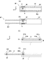
図5(A)及び(B)は位置決め機構の一例を示す。同図の例ではスライドレールSRに代わるスライドレールSR’に位置決め機構を設けた例を示す模式図である。スライドレールSR’は、ガイドレール151に代わるガイドレール151’と、可動レール24に代わる可動レール24’と、ベアリングユニットBUに代わるベアリングユニットBU’とを備える。
5A and 5B show an example of a positioning mechanism. In the example of the same figure, it is a schematic diagram which shows the example which provided the positioning mechanism in slide rail SR 'instead of slide rail SR. The slide rail SR 'includes a guide rail 151' that replaces the
スライドレールSR’は1段階で伸縮するスライドレールであり、ベアリングユニットBU’は中間レール154を備えずに、転動体Rとその保持器から構成され、ガイドレール151’のY方向の端部に固定配置されている。
The slide rail SR ′ is a slide rail that expands and contracts in one stage, and the bearing unit BU ′ does not include the
可動レール24’には、そのY方向の一方側部(図5(A)中では左側部)の下側の転動面に、転動体Rが係合する凹部RC1が形成されている。また、可動レール24’には、そのY方向の他方側部(図5(A)中では右側部)の下側の転動面に、転動体Rが係合する凹部RC2が形成されている。凹部RC1、RC2は転動体Rの数に応じてここでは4つずつ設けられている。凹部RC1、RC2は、転動体Rの1/4〜1/3程度が嵌まり込む深さの、球状の凹部となっている。
The
図5(A)は全閉時の態様を示し、図5(B)は全開時における態様を示す。図5(A)に示す全閉時では、転動体Rが凹部RC1と係合し、可動レール24’の位置(つまり扉2の位置)が固定される。扉2をY方向(図5(A)中では左方向)にやや強めにスライドさせると、転動体Rが凹部RC1から抜け出すようにして両者の係合、言い換えると転動体Rの転がり止めが解除されて扉2をスライド可能になる。扉2が全開位置に到達すると、図5(B)に示すように、転動体Rが凹部RC2と係合し、可動レール24’の位置(つまり扉2の位置)が固定される。扉2をY方向(図5(A)中では右方向)でチャンバ本体1側にやや強めにスライドさせると、転動体Rが凹部RC2から抜け出すようにして両者の係合が解除され、扉2をスライド可能となる。
FIG. 5A shows a mode when fully closed, and FIG. 5B shows a mode when fully opened. When fully closed as shown in FIG. 5A, the rolling element R is engaged with the recess RC1, and the position of the movable rail 24 '(that is, the position of the door 2) is fixed. When the
図5(C)及び(D)は位置決め機構の別例を示す。扉本体21の下面には、図3に示した弾性部材25が設けられている。押圧機構3による扉本体21のチャンバ本体1への押圧を解除してクランプを開放することで、扉本体21は弾性力によりチャンバ本体1から浮き上がった状態となる。扉本体21の上面には、図5(D)に示すように、係合する凹部223を有する突起部222a、222b(総称して突起部222という。)が設けられている。この突起部222は、扉本体21の上面に2箇所(図5(C)、図5(D)中では扉本体21の前方部および後方部に2箇所)設けられる。なお、ベアリング221a、221bを扉本体21に形成し、突起部222をチャンバ本体1側に設けるようにしてもよい。また、突起部222及びベアリング221の設置箇所としては、2箇所に限定するものではなく、3箇所以上であってもよい。
5C and 5D show another example of the positioning mechanism. The
図5(C)は全閉時の態様を示し、図5(D)は全開時における態様を示す。図5(C)に示す全閉時において、押圧機構3によるクランプを解除して扉本体21がチャンバ本体1から浮き上がることにより、両突起部222a、222bの凹部223がチャンバ本体1側に固定して設けられたベアリング221a、221bにそれぞれ嵌まり込む。
FIG. 5 (C) shows a mode when fully closed, and FIG. 5 (D) shows a mode when fully opened. When fully closed as shown in FIG. 5C, the clamp by the
このため、押圧機構3によるクランプを解除しても、扉本体21の位置が固定されることから、扉本体21がスライドフリーな状態となることはない。この状態から、図5(D)に示すように、扉2をY方向(図5(D)中では左方向)に所定の力以上でスライドさせると、それぞれの凹部223とベアリング221との係合が解除されて扉本体21がスライドされる。扉本体21が全開位置に到達すると、突起部222aの凹部223とベアリング221bとが係合し、扉本体21の位置が固定される。再度、扉を全閉する際は、扉本体21をY方向(図5(D)中では右方向)に所定の力以上でスライドさせると、突起部222aの凹部223とベアリング221bとの係合が解除され、扉本体21がスライド可能となる。
For this reason, even if the clamp by the
<処理装置>
基板を処理する処理装置(プロセスチャンバ等)のうち、チャンバ装置Aに隣接する処理装置に、扉2を収容する収容部を設けてもよい。図6(A)はその一例を示す処理システムの模式図である。
<Processing device>
Of the processing apparatus (process chamber or the like) that processes the substrate, a processing unit adjacent to the chamber apparatus A may be provided with a storage unit that stores the
チャンバ装置AのY方向一方側部(図6(A)中では右側部)にはプロセスチャンバ200が配置され、Y方向他方側部(図6(A)中では左側部)にはプロセスチャンバ201が配置されている。プロセスチャンバ201は、チャンバ装置Aの扉2のスライド方向側(扉2をスライド開放させる方向側)に配置されている。この例では、チャンバ装置Aはプロセスチャンバ200との間で基板の出し入れを行い、プロセスチャンバ201とは基板の出し入れは行わない構成を想定している。プロセスチャンバ201は、例えば、別の真空搬送装置との間で基板の出し入れが行われる。尤も、プロセスチャンバ201がチャンバ装置Aとの間で基板の出し入れを行う装置であってもよい。
The
プロセスチャンバ201は、その上部に、扉2を収容可能な収容空間202を有する。図6(B)は、プロセスチャンバ201の、チャンバ装置Aに対向する面(以下、側面という)201aの正面図を示している。プロセスチャンバ201の側面201aには、スロット部202aが形成されている。スロット部202aは開放された扉2と対向する位置に配置されており、カバー203で開閉可能となっている。
The
扉2を開放する場合、図6(C)に示すようにカバー203を開いて、扉2をY方向にスライドさせる。すると、スロット部202aから扉2が収容部202内に挿入され、収容される。このようにプロセスチャンバ201に扉2を収容可能な構成とすることにより、扉2の開放のための空間を避けてプロセスチャンバ201を配置する必要がなく、言い換えると、扉2をスライド開放させるためだけの領域(扉2のほぼ1枚分に相当する水平領域)を設ける必要がない。その結果、装置のレイアウトの自由度を向上できると共に、図6(A)に示した装置システム全体のフットプリントを縮小することができる。
When the
A チャンバ装置、SR スライド機構、1 チャンバ本体、2 扉、3 押圧機構、21 扉本体、22 支持機構 A chamber device, SR slide mechanism, 1 chamber body, 2 doors, 3 pressing mechanism, 21 door body, 22 support mechanism
Claims (5)
前記開口部を開閉する扉と、
前記チャンバ本体に設けられ、前記開口部に位置する前記扉を前記チャンバ本体側に押圧する押圧機構と、
前記チャンバ本体に対して前記扉をスライド可能に支持するガイド機構と、を備え、
前記扉は、
前記開口部を覆う部分を含み、前記押圧機構に押圧される扉本体と、
前記ガイド機構にスライド可能に支持されると共に、前記扉本体を前記チャンバ本体における前記上面から離間する方向に付勢する支持機構と、を備え、
前記支持機構は、
前記扉本体を支持する第1の部材と、
前記ガイド機構に対してスライドされる第2の部材と、
前記第1の部材と前記第2の部材との間に介在される弾性部材と、を備える、
ことを特徴とするチャンバ装置。 A chamber body with an opening on the top surface;
A door that opens and closes the opening;
A pressing mechanism that is provided in the chamber body and presses the door located at the opening to the chamber body side;
A guide mechanism that slidably supports the door with respect to the chamber body,
The door
Including a portion covering the opening, and a door body pressed by the pressing mechanism;
While being slidably supported by the guide mechanism, e Bei and a support mechanism for urging in a direction away from said upper surface in said chamber body and the door body,
The support mechanism is
A first member that supports the door body;
A second member slid relative to the guide mechanism;
An elastic member interposed between the first member and the second member,
A chamber apparatus.
前記開口部に対する前記扉の全開位置と全閉位置とにおいて、前記扉の位置を固定する位置決め機構を備える、
ことを特徴とするチャンバ装置。 A chamber according to claim 1 Symbol placement,
A positioning mechanism for fixing the position of the door at the fully open position and the fully closed position of the door with respect to the opening;
A chamber apparatus.
前記ガイド機構は、
前記チャンバ本体に固定されるガイドフレームと、
前記ガイドフレーム内に設けられると共に前記第2の部材に係合され、前記扉を前記ガイドフレームの延長方向に沿ってスライドさせるベアリングユニットと、
を備え、
前記位置決め機構は、前記ベアリングユニットにおける転動体と係合され、前記第2の部材に設けられる凹部を備える、
ことを特徴とするチャンバ装置。 The chamber apparatus according to claim 2 , wherein
The guide mechanism is
A guide frame fixed to the chamber body;
A bearing unit provided in the guide frame and engaged with the second member to slide the door along the extending direction of the guide frame;
With
The positioning mechanism includes a recess that is engaged with a rolling element in the bearing unit and is provided in the second member.
A chamber apparatus.
前記押圧機構は、トグルクランプである、
ことを特徴とするチャンバ装置。 The chamber apparatus according to any one of claims 1 to 3 ,
The pressing mechanism is a toggle clamp.
A chamber apparatus.
基板を処理する処理装置と、を備え、
前記チャンバ装置は、
上面に開口部を備えるチャンバ本体と、
前記開口部を開閉する扉と、
前記チャンバ本体に設けられ、前記開口部に位置する前記扉を前記チャンバ本体側に押圧する押圧機構と、
前記チャンバ本体に対して前記扉をスライド可能に支持するガイド機構と、を備え、
前記扉は、
前記開口部を覆う部分を含み、前記押圧機構に押圧される扉本体と、
前記ガイド機構にスライド可能に支持されると共に、前記扉本体を前記チャンバ本体における前記上面から離間する方向に付勢する支持機構と、を備え、
前記処理装置は、
前記チャンバ装置の前記扉のスライド方向側に配置され、かつ、開放された前記扉と対向する位置に配設されたスロット部と、
前記スロット部と連通して前記扉を収容する収容部と、を備える、
ことを特徴とする処理システム。 And blood Yanba apparatus,
A processing apparatus for processing a substrate,
The chamber apparatus includes:
A chamber body with an opening on the top surface;
A door that opens and closes the opening;
A pressing mechanism that is provided in the chamber body and presses the door located at the opening to the chamber body side;
A guide mechanism that slidably supports the door with respect to the chamber body,
The door
Including a portion covering the opening, and a door body pressed by the pressing mechanism;
A support mechanism that is slidably supported by the guide mechanism and urges the door body in a direction away from the upper surface of the chamber body,
The processor is
A slot portion disposed on the sliding direction side of the door of the chamber device and disposed at a position facing the opened door;
A housing portion communicating with the slot portion and housing the door;
A processing system characterized by that.
Priority Applications (1)
| Application Number | Priority Date | Filing Date | Title |
|---|---|---|---|
| JP2014073561A JP6290686B2 (en) | 2014-03-31 | 2014-03-31 | Chamber apparatus and processing system |
Applications Claiming Priority (1)
| Application Number | Priority Date | Filing Date | Title |
|---|---|---|---|
| JP2014073561A JP6290686B2 (en) | 2014-03-31 | 2014-03-31 | Chamber apparatus and processing system |
Publications (3)
| Publication Number | Publication Date |
|---|---|
| JP2015198100A JP2015198100A (en) | 2015-11-09 |
| JP2015198100A5 JP2015198100A5 (en) | 2017-04-06 |
| JP6290686B2 true JP6290686B2 (en) | 2018-03-07 |
Family
ID=54547648
Family Applications (1)
| Application Number | Title | Priority Date | Filing Date |
|---|---|---|---|
| JP2014073561A Active JP6290686B2 (en) | 2014-03-31 | 2014-03-31 | Chamber apparatus and processing system |
Country Status (1)
| Country | Link |
|---|---|
| JP (1) | JP6290686B2 (en) |
Family Cites Families (6)
| Publication number | Priority date | Publication date | Assignee | Title |
|---|---|---|---|---|
| JPS5483021U (en) * | 1977-11-24 | 1979-06-12 | ||
| JPS5560761A (en) * | 1978-10-31 | 1980-05-08 | Murata Mach Ltd | Double shutter |
| JP2001008757A (en) * | 1999-07-01 | 2001-01-16 | Nanbu Plastics Co Ltd | Drawer guiding mechanism, drawer and suspending rail |
| JP4699705B2 (en) * | 2004-03-09 | 2011-06-15 | 日本アキュライド株式会社 | Slide rail storage holding device |
| JP2011024630A (en) * | 2009-07-21 | 2011-02-10 | Okamura Corp | Desk apparatus |
| US8261928B2 (en) * | 2010-06-02 | 2012-09-11 | Eaton Corporation | Swing bolt splash shield |
-
2014
- 2014-03-31 JP JP2014073561A patent/JP6290686B2/en active Active
Also Published As
| Publication number | Publication date |
|---|---|
| JP2015198100A (en) | 2015-11-09 |
Similar Documents
| Publication | Publication Date | Title |
|---|---|---|
| JP5244097B2 (en) | Device with transport pod and interface for substrates | |
| JP5450363B2 (en) | Container for holding wafer | |
| US9599233B2 (en) | Gate valve | |
| US8171964B2 (en) | Apparatus and method for opening/closing lid of closed container, gas replacement apparatus using same, and load port apparatus | |
| US9685359B2 (en) | Load port device | |
| TWI391591B (en) | Gate valve | |
| JP6375186B2 (en) | Substrate storage container, load port device, and substrate processing apparatus | |
| JP5736686B2 (en) | Load port | |
| CN112714950B (en) | Pin lifting device | |
| JP2008283215A (en) | Substrate processing device | |
| TWI574896B (en) | Substrate container, a load port apparatus, and a substrate treating apparatus | |
| US9269599B2 (en) | Substrate relay apparatus, substrate relay method, and substrate processing apparatus | |
| JP6290686B2 (en) | Chamber apparatus and processing system | |
| JP4338205B2 (en) | Pod clamp unit, load port with pod clamp unit, mini environment system with pod and load port | |
| TW201523776A (en) | Loading port apparatus and substrate processing apparatus | |
| KR101687734B1 (en) | Chamber apparatus and treatment system | |
| US10043689B2 (en) | Chamber apparatus and processing system | |
| JP2014020552A (en) | Gate valve using inclination driving | |
| JP4848916B2 (en) | Clamp mechanism | |
| TWI600853B (en) | Chamber device and processing system | |
| CN113454007B (en) | Lid opening and closing device | |
| JP2011134993A (en) | Vacuum processing apparatus | |
| JP2005076845A (en) | Gate valve | |
| KR102614457B1 (en) | High pressure wafer processing apparatus | |
| CN110379753A (en) | Substrate transport system, storage medium and board transport method |
Legal Events
| Date | Code | Title | Description |
|---|---|---|---|
| A521 | Written amendment |
Free format text: JAPANESE INTERMEDIATE CODE: A523 Effective date: 20170301 |
|
| A621 | Written request for application examination |
Free format text: JAPANESE INTERMEDIATE CODE: A621 Effective date: 20170301 |
|
| A977 | Report on retrieval |
Free format text: JAPANESE INTERMEDIATE CODE: A971007 Effective date: 20171120 |
|
| A131 | Notification of reasons for refusal |
Free format text: JAPANESE INTERMEDIATE CODE: A131 Effective date: 20171222 |
|
| A521 | Written amendment |
Free format text: JAPANESE INTERMEDIATE CODE: A523 Effective date: 20180119 |
|
| TRDD | Decision of grant or rejection written | ||
| A01 | Written decision to grant a patent or to grant a registration (utility model) |
Free format text: JAPANESE INTERMEDIATE CODE: A01 Effective date: 20180129 |
|
| A61 | First payment of annual fees (during grant procedure) |
Free format text: JAPANESE INTERMEDIATE CODE: A61 Effective date: 20180208 |
|
| R150 | Certificate of patent or registration of utility model |
Ref document number: 6290686 Country of ref document: JP Free format text: JAPANESE INTERMEDIATE CODE: R150 |
|
| R250 | Receipt of annual fees |
Free format text: JAPANESE INTERMEDIATE CODE: R250 |