JP6290258B2 - Cutting tool with a cutting insert having a non-contact side abdomen - Google Patents
Cutting tool with a cutting insert having a non-contact side abdomen Download PDFInfo
- Publication number
- JP6290258B2 JP6290258B2 JP2015552197A JP2015552197A JP6290258B2 JP 6290258 B2 JP6290258 B2 JP 6290258B2 JP 2015552197 A JP2015552197 A JP 2015552197A JP 2015552197 A JP2015552197 A JP 2015552197A JP 6290258 B2 JP6290258 B2 JP 6290258B2
- Authority
- JP
- Japan
- Prior art keywords
- insert
- cutting
- cutting tool
- axis
- Prior art date
- Legal status (The legal status is an assumption and is not a legal conclusion. Google has not performed a legal analysis and makes no representation as to the accuracy of the status listed.)
- Active
Links
- 238000005520 cutting process Methods 0.000 title claims description 146
- 210000001015 abdomen Anatomy 0.000 title claims description 7
- 230000002093 peripheral effect Effects 0.000 claims description 8
- 238000004519 manufacturing process Methods 0.000 description 2
- 238000000748 compression moulding Methods 0.000 description 1
- 238000005336 cracking Methods 0.000 description 1
- 238000005516 engineering process Methods 0.000 description 1
- 238000012986 modification Methods 0.000 description 1
- 230000004048 modification Effects 0.000 description 1
- 238000005245 sintering Methods 0.000 description 1
- UONOETXJSWQNOL-UHFFFAOYSA-N tungsten carbide Chemical compound [W+]#[C-] UONOETXJSWQNOL-UHFFFAOYSA-N 0.000 description 1
Images


Classifications
-
- B—PERFORMING OPERATIONS; TRANSPORTING
- B23—MACHINE TOOLS; METAL-WORKING NOT OTHERWISE PROVIDED FOR
- B23B—TURNING; BORING
- B23B27/00—Tools for turning or boring machines; Tools of a similar kind in general; Accessories therefor
- B23B27/14—Cutting tools of which the bits or tips or cutting inserts are of special material
- B23B27/16—Cutting tools of which the bits or tips or cutting inserts are of special material with exchangeable cutting bits or cutting inserts, e.g. able to be clamped
- B23B27/1644—Cutting tools of which the bits or tips or cutting inserts are of special material with exchangeable cutting bits or cutting inserts, e.g. able to be clamped with plate-like cutting inserts of special shape clamped by a clamping member acting almost perpendicularly on the chip-forming plane and at the same time upon the wall of a hole in the cutting insert
- B23B27/1651—Cutting tools of which the bits or tips or cutting inserts are of special material with exchangeable cutting bits or cutting inserts, e.g. able to be clamped with plate-like cutting inserts of special shape clamped by a clamping member acting almost perpendicularly on the chip-forming plane and at the same time upon the wall of a hole in the cutting insert characterised by having a special shape
-
- B—PERFORMING OPERATIONS; TRANSPORTING
- B23—MACHINE TOOLS; METAL-WORKING NOT OTHERWISE PROVIDED FOR
- B23B—TURNING; BORING
- B23B27/00—Tools for turning or boring machines; Tools of a similar kind in general; Accessories therefor
- B23B27/04—Cutting-off tools
-
- B—PERFORMING OPERATIONS; TRANSPORTING
- B23—MACHINE TOOLS; METAL-WORKING NOT OTHERWISE PROVIDED FOR
- B23B—TURNING; BORING
- B23B27/00—Tools for turning or boring machines; Tools of a similar kind in general; Accessories therefor
- B23B27/14—Cutting tools of which the bits or tips or cutting inserts are of special material
- B23B27/16—Cutting tools of which the bits or tips or cutting inserts are of special material with exchangeable cutting bits or cutting inserts, e.g. able to be clamped
- B23B27/1603—Cutting tools of which the bits or tips or cutting inserts are of special material with exchangeable cutting bits or cutting inserts, e.g. able to be clamped with specially shaped plate-like exchangeable cutting inserts, e.g. chip-breaking groove
- B23B27/1611—Cutting tools of which the bits or tips or cutting inserts are of special material with exchangeable cutting bits or cutting inserts, e.g. able to be clamped with specially shaped plate-like exchangeable cutting inserts, e.g. chip-breaking groove characterised by having a special shape
-
- B—PERFORMING OPERATIONS; TRANSPORTING
- B23—MACHINE TOOLS; METAL-WORKING NOT OTHERWISE PROVIDED FOR
- B23B—TURNING; BORING
- B23B27/00—Tools for turning or boring machines; Tools of a similar kind in general; Accessories therefor
- B23B27/14—Cutting tools of which the bits or tips or cutting inserts are of special material
- B23B27/16—Cutting tools of which the bits or tips or cutting inserts are of special material with exchangeable cutting bits or cutting inserts, e.g. able to be clamped
- B23B27/1614—Cutting tools of which the bits or tips or cutting inserts are of special material with exchangeable cutting bits or cutting inserts, e.g. able to be clamped with plate-like cutting inserts of special shape clamped against the walls of the recess in the shank by a clamping member acting upon the wall of a hole in the insert
- B23B27/1622—Cutting tools of which the bits or tips or cutting inserts are of special material with exchangeable cutting bits or cutting inserts, e.g. able to be clamped with plate-like cutting inserts of special shape clamped against the walls of the recess in the shank by a clamping member acting upon the wall of a hole in the insert characterised by having a special shape
-
- B—PERFORMING OPERATIONS; TRANSPORTING
- B23—MACHINE TOOLS; METAL-WORKING NOT OTHERWISE PROVIDED FOR
- B23B—TURNING; BORING
- B23B29/00—Holders for non-rotary cutting tools; Boring bars or boring heads; Accessories for tool holders
- B23B29/04—Tool holders for a single cutting tool
- B23B29/043—Tool holders for a single cutting tool with cutting-off, grooving or profile cutting tools, i.e. blade- or disc-like main cutting parts
-
- B—PERFORMING OPERATIONS; TRANSPORTING
- B23—MACHINE TOOLS; METAL-WORKING NOT OTHERWISE PROVIDED FOR
- B23B—TURNING; BORING
- B23B2200/00—Details of cutting inserts
- B23B2200/36—Other features of cutting inserts not covered by B23B2200/04 - B23B2200/32
- B23B2200/369—Mounted tangentially, i.e. where the rake face is not the face with the largest area
-
- B—PERFORMING OPERATIONS; TRANSPORTING
- B23—MACHINE TOOLS; METAL-WORKING NOT OTHERWISE PROVIDED FOR
- B23B—TURNING; BORING
- B23B2205/00—Fixation of cutting inserts in holders
- B23B2205/12—Seats for cutting inserts
-
- Y—GENERAL TAGGING OF NEW TECHNOLOGICAL DEVELOPMENTS; GENERAL TAGGING OF CROSS-SECTIONAL TECHNOLOGIES SPANNING OVER SEVERAL SECTIONS OF THE IPC; TECHNICAL SUBJECTS COVERED BY FORMER USPC CROSS-REFERENCE ART COLLECTIONS [XRACs] AND DIGESTS
- Y10—TECHNICAL SUBJECTS COVERED BY FORMER USPC
- Y10T—TECHNICAL SUBJECTS COVERED BY FORMER US CLASSIFICATION
- Y10T407/00—Cutters, for shaping
- Y10T407/22—Cutters, for shaping including holder having seat for inserted tool
- Y10T407/2272—Cutters, for shaping including holder having seat for inserted tool with separate means to fasten tool to holder
- Y10T407/2274—Apertured tool
-
- Y—GENERAL TAGGING OF NEW TECHNOLOGICAL DEVELOPMENTS; GENERAL TAGGING OF CROSS-SECTIONAL TECHNOLOGIES SPANNING OVER SEVERAL SECTIONS OF THE IPC; TECHNICAL SUBJECTS COVERED BY FORMER USPC CROSS-REFERENCE ART COLLECTIONS [XRACs] AND DIGESTS
- Y10—TECHNICAL SUBJECTS COVERED BY FORMER USPC
- Y10T—TECHNICAL SUBJECTS COVERED BY FORMER US CLASSIFICATION
- Y10T407/00—Cutters, for shaping
- Y10T407/23—Cutters, for shaping including tool having plural alternatively usable cutting edges
Description
発明の分野
本発明は、概して、切削インサートと、適合するインサートポケットとを有する切削工具に関し、詳細には、スイス型(Swiss type)切削工具に関する。
The present invention relates generally to cutting tools having cutting inserts and matching insert pockets, and more particularly to Swiss type cutting tools.
発明の背景
切削工具は、切削インサートを保持するためのポケットが形成された工具ホルダを有する。ポケットは、切削インサートが当接するための複数の壁と、切削インサートをインサートポケットに締結し得るねじを受け入れるためのねじ穴とを有し得る。例えば、スイス型自動機械では、切削工具は、矩形状のバーから一般的に作製される工具シャンクを有する。
BACKGROUND OF THE INVENTION A cutting tool has a tool holder in which a pocket for holding a cutting insert is formed. The pocket may have a plurality of walls for the cutting insert to abut and a threaded hole for receiving a screw that can fasten the cutting insert to the insert pocket. For example, in Swiss-type automatic machines, the cutting tool has a tool shank that is typically made from a rectangular bar.
インサートポケットが形成された切削工具、およびスイス型切削工具は、例えば、スイス特許第664102号、スイス特許第686935号、特開平11−156605号、欧州特許第0213076号、欧州特許第1657012号、米国特許第4462725号、米国特許第4890961号、米国特許第5649579号、米国特許第5816753号、米国特許第6155754号、米国特許第6579043号、米国特許第6960049号、米国特許第7001115号、米国特許出願公開第2010/0104390号、および特開2007−203379号に示されている。 A cutting tool in which an insert pocket is formed and a Swiss type cutting tool are, for example, Swiss Patent No. 664102, Swiss Patent No. 686935, Japanese Patent Laid-Open No. 11-156605, European Patent No. 0213076, European Patent No. 1657012, US U.S. Patent No. 4,462,725, U.S. Patent No. 4,890,961, U.S. Patent No. 5,649,579, U.S. Patent No. 5,816,753, U.S. Patent No. 6,155,754, U.S. Patent No. 6579043, U.S. Patent No. 6,696,0049, U.S. Patent No. 7,001115, U.S. Patent Application This is disclosed in Japanese Patent Publication No. 2010/0104390 and Japanese Patent Application Laid-Open No. 2007-203379.
適合するインサートポケット内に切削インサートが保持される切削工具であって、インサートホルダが切削インサートをインサート中心軸の両側で確実に保持し、インサートが非当接側腹部を有する切削工具を提供することが本出願の主題の目的である。 A cutting tool in which a cutting insert is held in a suitable insert pocket, the insert holder securely holding the cutting insert on both sides of the insert central axis, and the cutting tool has a non-contacting side abdomen Is the purpose of the subject matter of this application.
発明の概要
本出願の主題によれば、切削工具であって、
反対側にある第1および第2の側表面と、前方方向から後方方向へ延びる縦方向主軸および横方向ポケット軸を有するインサートポケットとを含む工具ホルダ、および
縦方向の第1軸および横方向の第2軸を有する切削インサートであって、2つの端部表面およびそれらの間に延在する周囲表面を含み、第1軸に沿って配置された、2つの反対側にある切削部分およびそれらの間のクランプ部分を有する切削インサート
を含み、
インサートポケットが、
第2側表面と結合され、ポケット軸の前方に配置され、前方当接表面を有する前方クランプ部分、および
第1側表面と結合され、ポケット軸の後方に配置され、第1および第2の後方当接表面を有する後方クランプ部分
を含み、
切削インサートの周囲表面上の、2つの反対側にある側腹部が、切削部分に沿って、および部分的にクランプ部分に沿って反対方向に延在し、第1および第2のクランプ表面が各側腹部に隣接して配置され、
切削工具の組立位置において、一方の側腹部に隣接する第1および第2のクランプ表面が、それぞれ第1および第2の後方当接表面に当接し、他方の側腹部に隣接する第1クランプ表面が、前方当接表面に当接し、側腹部はどちらも工具ホルダに当接しない、
切削工具が提供される。
SUMMARY OF THE INVENTION According to the subject matter of the present application, a cutting tool comprising:
A tool holder comprising first and second side surfaces on opposite sides, an insert pocket having a longitudinal main axis and a lateral pocket axis extending from the front direction to the rear direction, and a longitudinal first axis and a lateral direction A cutting insert having a second axis, comprising two end surfaces and a peripheral surface extending therebetween, two opposite cutting portions disposed along the first axis and their Including a cutting insert having a clamping portion between,
Insert pocket
A front clamp portion coupled to the second side surface and disposed in front of the pocket shaft and having a forward abutment surface; and coupled to the first side surface and disposed rearward of the pocket shaft and the first and second rear surfaces Including a rear clamp portion having an abutment surface;
Two opposite flank portions on the peripheral surface of the cutting insert extend in opposite directions along the cutting portion and partially along the clamping portion, and the first and second clamping surfaces are each Placed adjacent to the flank,
The first clamp surface adjacent to the first and second rear abutment surfaces and the first clamp surface adjacent to the other flank at the assembly position of the cutting tool, respectively. But abuts against the front abutment surface and neither flank abuts against the tool holder,
A cutting tool is provided.
本出願の主題の実施形態によれば、ポケットねじ穴がポケット軸に沿ってインサートポケットを貫通し、インサートねじ穴が第2軸に沿って切削インサートのクランプ部分を貫通する。 According to embodiments of the present subject matter, the pocket screw hole extends through the insert pocket along the pocket axis, and the insert screw hole extends through the clamp portion of the cutting insert along the second axis.
本出願の主題の別の実施形態によれば、クランプねじがインサートねじ穴を貫通し、ポケットねじ穴と係合し、切削インサートをインサートポケットに締結する。 According to another embodiment of the present subject matter, a clamp screw passes through the insert screw hole, engages with the pocket screw hole, and fastens the cutting insert to the insert pocket.
本出願の主題のさらなる実施形態によれば、ポケット軸に沿った切削工具の上面図において、切削インサートの側腹部の少なくとも一方が、工具ホルダの側表面のうちのそれぞれの1つと面一である。 According to a further embodiment of the present subject matter, in a top view of the cutting tool along the pocket axis, at least one of the flank portions of the cutting insert is flush with each one of the side surfaces of the tool holder. .
本出願の主題によれば、縦方向の第1軸および横方向の第2軸を有し、第2軸の周りで180°の回転対称を有する切削インサートであって、
2つの端部表面およびそれらの間の周囲表面、
縦方向の第1軸に沿って配置された、2つの反対側にある切削部分およびそれらの間のクランプ部分、
横方向の第2軸に沿って切削インサートのクランプ部分を貫通するインサートねじ穴
を含み、
周囲表面が、
対応する切削部分に沿って、および部分的にクランプ部分に沿って反対方向に延在する2つの反対側にある側腹部であって、各側腹部がインサート側面を画定し、2つの反対側にある側腹部のインサート側面が、それらの間でインサート幅を画定する2つの側腹部を含み、
各側腹部が、それに隣接して、対応する切削部分と反対の側に、第1および第2のクランプ表面を有し、
横方向の第2軸に沿った切削インサートの上面図において、第1および第2のクランプ表面が、
隣接するインサート側面から窪められ、
互いに傾けられ、横方向の第2軸に向かって集束し、
非クランプインサート表面によって互いに離間される
切削インサートが同じく提供される。
According to the subject matter of the present application, a cutting insert having a longitudinal first axis and a transverse second axis and having a rotational symmetry of 180 ° about the second axis,
Two end surfaces and a surrounding surface between them,
Two opposite cutting parts and a clamping part between them, arranged along a first longitudinal axis;
Including an insert screw hole extending through a clamping portion of the cutting insert along a second transverse axis;
The surrounding surface is
Two opposite flank portions extending in opposite directions along corresponding cutting portions and partially along the clamping portion, each flank portion defining an insert side surface and An flank insert side includes two flank defining an insert width therebetween;
Each flank has first and second clamping surfaces adjacent to and opposite the corresponding cutting portion;
In a top view of the cutting insert along the second transverse axis, the first and second clamping surfaces are:
Recessed from the side of the adjacent insert,
Tilted towards each other and focused towards a second lateral axis,
Also provided are cutting inserts spaced from each other by unclamped insert surfaces.
図面の簡単な説明
本発明をより深く理解するため、および実際に本発明をどのように実行することができるかを示すため、次に添付の図面を参照する。
BRIEF DESCRIPTION OF THE DRAWINGS For a better understanding of the present invention and to show how it can be practiced, reference is now made to the accompanying drawings.
図を単純および明確にするために、図面に示される要素は必ずしも一定の縮尺比で描かれていないことは認識されよう。例えば、一部の要素の寸法は、明確にするために他の要素に対して誇張されている場合があり、またはいくつかの物理的構成要素が1つの機能的ブロックまたは要素の中に含まれている場合がある。さらに、適切と考えられる場合、対応する要素または類似の要素を示すために参照番号はいくつかの図面を通して繰り返される場合がある。 It will be appreciated that for simplicity and clarity of illustration, elements shown in the drawings have not necessarily been drawn to scale. For example, the dimensions of some elements may be exaggerated with respect to other elements for clarity, or some physical components may be included in one functional block or element. There may be. Further, where considered appropriate, reference numerals may be repeated throughout the several figures to indicate corresponding or analogous elements.
発明の詳細な説明
以下の記載中、本発明の様々な態様が記載される。説明を目的として、特定の構成および詳細が、本発明の完全な理解を提供するために記載される。しかしながら、本明細書に提示された特定の詳細なしに本発明を実行できることも当業者には明白である。さらに、本発明を曖昧にしないように、周知の特徴は省略または簡略化される場合がある。
DETAILED DESCRIPTION OF THE INVENTION In the following description, various aspects of the present invention will be described. For purposes of explanation, specific configurations and details are set forth in order to provide a thorough understanding of the present invention. However, it will be apparent to those skilled in the art that the present invention may be practiced without the specific details presented herein. Furthermore, well-known features may be omitted or simplified in order not to obscure the present invention.
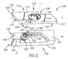
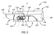
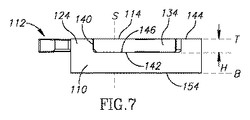
図1〜9を参照する。それらは、本発明による切削工具100を様々な見た目および位置で示している。切削工具100は工具ホルダ102および切削インサート112を含む。工具ホルダ102は、その前端部106にインサートポケット104が形成されている。インサートポケット104は、前方方向DFから後方方向DRへ延びる縦方向主軸Mと、横方向ポケット軸Sとを有する。工具ホルダ102は、縦方向に延在する反対側の第1および第2側表面108、110と、それらの間に延在する上表面および底表面144、154とを有する。インサートポケット104は上表面144に開口する。上表面144は上面Tを画定する。上面Tは側表面108、110に対して実質的に垂直である。底表面154は上表面144の反対側にあり、底面Bを画定する。いくつかの実施形態では、底面Bは上面Tと平行であり得る(例えば、ポケット軸Sに対して垂直に取られた図7および8の側面図に示されるように)。
Reference is made to FIGS. They show the
インサートポケット104は前方クランプ部分124および後方クランプ部分128を有する。前方クランプ部分124は、第2側表面110と結合され、ポケット軸Sの前方に配置され、後方クランプ部分128は、第1側表面108と結合され、ポケット軸Sの後方に配置される。前方クランプ部分124は、縦方向に延在する前方当接表面126を有する。後方クランプ部分128は、第1および第2の後方当接表面130、132を有し、それらは互いに傾けられ、ポケット軸Sに向かって集束する。第1および第2の後方当接表面130、132は、非当接ホルダ表面131によって互いに離間されてもよい。非当接ホルダ表面131は、上面図で見るとき凸状であってもよい。さらに、ねじ切りされたポケットねじ穴150が、ポケット軸Sに沿ってインサートポケット104を貫通する。インサートポケット104はまた、ポケット当接表面146を有する。ポケット当接表面146は工具ホルダ102の上表面144と平行であってもよく、また上表面144からポケット高さHだけ離間されてもよい(図7)。
The
第1および第2の後方当接表面130、132および前方当接表面126は、上面Tに対して実質的に垂直に延在してもよい。第2の後方当接表面132は、例えば図5の上面図で示されるように、第1後方当接表面130に対して実質的に垂直であってもよい。さらに図5に示されるように、前方当接表面126は第2側表面110と実質的に平行に延在してもよい。同様に、第1後方当接表面130は第1側表面108と実質的に平行に延在してもよい。加えて、前方当接表面126は第1後方当接表面130と実質的に平行に延在してもよい。
The first and second rear abutment surfaces 130, 132 and the
切削インサート112はS字形であり、縦方向第1軸Iおよび横方向第2軸Lを有する。切削インサート112は割出し可能であってもよく、第2軸Lの周りで180°の回転対称を示す。切削インサート112は、2つの端部表面114と、それらの間に延在する周囲表面116とを有する。2つの反対側の切削部分118は切削インサート112に沿って形成され、中央クランプ部分120はそれらの間に位置付けられ、第1軸Iに沿って配置される。各切削部分118は切れ刃122を有する。さらに、インサートねじ穴152が第2軸Lに沿ってクランプ部分120を貫通する。切削インサート112のクランプ部分120は、端部表面114の一方に配置されたインサート当接表面142を有する。
The cutting
切削インサート112の周囲表面116は、2つの反対側にある側腹部134を有し、各側腹部134はインサート側面Pを画定し、第2軸Lの両側に配置される。インサート側面Pは互いに平行であり、インサート幅Wだけ離間される(図5)。従って、側腹部134によって画定されるインサート幅は、縦方向第1軸Iと横方向第2軸Lとによって画定される仮想面に対して垂直な方向に延在する。2つの反対側にある側腹部134は、それらの関連する切削部分118に沿って、切れ刃122から、部分的にクランプ部分120に沿って反対方向に延在する。第2軸Lに沿って取られた切削インサート112の端面図において(図5参照)、側腹部134は、切れ刃122から、前方方向DFおよび後方方向DRのうちの正反対の方向に縦方向に延在する。窪められたクランプコーナ136が、各側腹部134の後ろに、すなわち各切れ刃122から離れる方向に配置される。各クランプコーナ136は、(各側腹部134に隣接して配置された)第1および第2のクランプ表面138、140を有し、それらは互いに傾けられ、第2軸Lに向かって集束する。第1および第2クランプ表面138、140は、非クランプインサート表面139だけ互いに離間されてもよい。非クランプインサート表面139は凹状であってもよく(すなわち上面図において)、周囲表面116上で、第2インサート軸L(この周りで切削インサート112は180°の回転対称を有する)に最も近い接近地点を形成する。
The
切削工具100は組立位置(例えば図1および3)と分解位置(例えば図2および4)の間で移動可能である。分解位置において、切削インサート112は、工具ホルダ102から分離される。組立位置において、切削インサート112は、例えばクランプねじ148によって、インサートポケット104内に保持される。クランプねじ148はポケット軸Sに沿ってインサートねじ穴152を通って延在し、ポケットねじ穴150とねじ係合し、切削インサート112をインサートポケット104に締結する。ポケット軸Sは、切削インサート112を後方に締め付ける状態で保持するために、インサートの第2軸Lのわずか後方に、すなわち主軸Mに沿って延びてもよい。
The
組立位置において、クランプコーナ136のうちの一方の(すなわち側腹部134のうちの一方に隣接し且つインサート側面Pから窪められている)第1および第2のクランプ表面138、140は、それぞれ第1および第2の後方当接表面130、132と当接する。クランプコーナ136の他方の(すなわち他方の側腹部134に隣接する)第1クランプ表面138は、前方クランプ部分124の前方当接表面126と当接する。インサート当接表面142はポケット当接表面146と当接する。特に、組立位置において、切削インサート112の側腹部134はどちらも工具ホルダ102と当接しない、従って両側腹部134は非当接側腹部134であると見なされる。
In the assembled position, the first and second clamping surfaces 138, 140 of one of the clamp corners 136 (ie, adjacent to one of the
第2クランプ表面140の両方は、第1クランプ表面138の間に縦方向に配置される。これは、切削インサート112の保持においてさらなる安定性を提供し、このとき、2つの第1クランプ表面138はインサートポケット104に対して当接され、傾けられた第2クランプ表面140はそれらの間に縦方向に配置される。
Both second clamping surfaces 140 are disposed longitudinally between the first clamping surfaces 138. This provides additional stability in holding the cutting
前方クランプ部分124に近いクランプコーナ136の第2クランプ表面140は、前方クランプ部分124と接触しない(図7)。このようにして、切削インサート112は、第2軸Lの周りで、インサートポケット104に対して3つの箇所、すなわち、前方当接表面126、および第1および第2の後方当接表面138、140において、クランプされる。このことについては、切削インサート112の側腹部134の両方は、工具ホルダ102と当接しないままであってもよい。切削インサート112とインサートポケット104の間に別の当接箇所を得ることは必要とされないためである。
The
切削インサート112の当接箇所は、その切れ刃122から離間される。従って、クランプまたは切削作業のせいで当接箇所に適用されるあらゆる力または圧力は、切れ刃122に影響を及ぼさない。切れ刃122は、切削インサート112のクランプで発生する力に曝されず、そのような力のせいで破損する傾向が弱まり、それにより切削インサート112の寿命を延長する。さらに、切れ刃122の一方が切削作業中に損傷した場合(例えばクラックの発生または破断)、切削インサート112をインサートポケット104内でなおも割り出してクランプすることができ、そして他方の切れ刃122を切削作業においてさらに使用することができる。
The contact point of the cutting
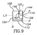
組立位置において、前方クランプ部分124に近い切削部分118は、工具ホルダ102の前方に延在する。これは例えば、図6に示されるようなポケット軸Sに沿って取られた、組み立てられた切削工具100の底面図において明らかである。さらに、切削インサート112の第1軸Iは、工具ホルダ102の主軸Mと一致してもよい。これは例えば、図5の上面図および(主軸Mに沿って取られた)図9の正面図において明らかである。
In the assembled position, the cutting
組み立てられた切削工具100をポケット軸Sに沿った上面図で見るとき(図5参照)、切削インサート112の側腹部134の少なくとも一方は、工具ホルダ102の側表面108、110のうちのそれぞれの一方と面一である。これは、本発明を、空間が制限された状態で、または複数のシャンクが互いに近接して配置された状態(これにより同じく切削工具100への接近が制限され得る)で、機械中で使用するとき、必要とされ得る。本出願の図面において、および特に図5の上面図において、側腹部134の両方は、工具ホルダ102の側表面108、110の両方と面一である。しかしながら、側腹部134の一方だけが、側表面108、110のうちのそれぞれの一方と面一であってもよい。
When the assembled
切削インサート112をインサートポケット104内に保持するために、または切削インサート112をそこから取り外すために、クランプねじ148はそれぞれポケットねじ穴150に締結される、またはそこから緩められる。しかしながら、本発明の実施形態によれば、クランプねじ148は、切削インサート112をインサートポケット104に取り付けるために、またはそこから取り外すために、ポケットねじ穴150から完全に引き抜かなくてもよい。代わりに、クランプねじ148を部分的に解放する一方、クランプねじ148をある特定の範囲までポケットねじ穴150とねじ係合した状態に維持することが必要であり得る(図2および4)。そのような実施形態では、インサートねじ穴152は、切削インサート112が特定の向きにおいてクランプねじ148の頭部を通り越すことを可能にするように設計される。これは、例えばインサートねじ穴152が第2軸Lに沿って可変断面を有するとき、達成可能であり、それによりインサートねじ穴152が、例えば第1軸Iの周りで切削インサート112を回転させるとき、クランプねじ148の頭部を通り越すことが可能になる。さらに、側腹部134はどちらも工具ホルダ102と当接しないので、切削インサート112を第1軸Iの周りで回転させることが可能である。側腹部134のどちらかが工具ホルダ102に対して当接されていたなら、側腹部134は切削インサート112の第1軸I周りのそのような回転を妨害したであろうし、従って締付ねじの頭部を越えるそのようなインサート取外しの使用を阻むであろう。
In order to hold the
添付図面に示される切削工具100はスイス型切削工具であり、工具ホルダ102は、縦方向主軸Mに沿って取られた図9の正面図に示されるように、矩形の横方向断面を有する。しかしながら、本発明は、スイス型自動機械(例えば旋盤)に使用される種類の切削工具に限定されず、切削インサートをインサートポケットに固定すべきである多くの種類の切削工具に適用可能であることを理解すべきである。例えば切削工具100は、工具ホルダ102が非矩形断面を有する一方で本発明による切削インサートおよびインサートポケットの特徴を採用する異なる種類の切削工具であってもよい。
The
切削インサート112の当接箇所はその周囲表面116上にあるがインサート当接表面142を除くことは認識されよう。従って、インサート端部表面114上に、および対応してポケット当接表面146上に、突出部および凹部など、当接構造もクランプ構造も形成する必要はない。換言すると、切削インサート112のクランプ部分120の高さ(すなわち、端部表面114間の横方向距離)は、実質的に一定である。このようにして、切削インサート112の製造は、例えば切削インサート112が超硬合金(例えば炭化タングステン)を圧縮成形し、続いて焼結することによって形成されるとき、簡略化される。例えば切削インサート112の製造は、切削インサート112がその中でプレス成形される金型を単純化することによって、より簡単にされる。
It will be appreciated that the abutment location of the cutting
切削インサート112の側腹部134は当接もクランプもしないので側腹部134に隣接する工具ホルダ102に当接構造もクランプ表面も形成する必要はないことをさらに認識すべきである。これにより、インサート幅Wを工具ホルダ102の幅と、すなわち側表面108、110の間の距離と実質的に等しくすることが可能になる。側腹部134のどちらかが工具ホルダ102に対して当接されている場合、それはインサート幅Wが工具ホルダ102の幅より小さいことを意味し得る。
It should further be appreciated that the
1つまたは複数の特定実施形態を参照して本発明を記載してきたが、本記載は総じて例であることが意図され、示される実施形態に本発明を制限していると解釈すべきでない。本明細書に特に示されないが本発明の範囲内にある様々な修正を当業者は思い付く可能性があることが認識される。 Although the invention has been described with reference to one or more specific embodiments, the description is intended to be exemplary in general and should not be construed as limiting the invention to the illustrated embodiments. It will be appreciated that those skilled in the art may come up with various modifications not specifically shown herein but within the scope of the invention.
Claims (18)
反対側にある第1および第2側表面(108、110)と、前方方向(DF)から後方方向(DR)へ延びる縦方向主軸(M)および横方向ポケット軸(S)を有するインサートポケット(104)とを含む工具ホルダ(102)と、
縦方向の第1軸(I)および横方向の第2軸(L)を有する切削インサート(112)であって、2つの端部表面(114)およびそれらの間の周囲表面(116)を含み、前記第1軸(I)に沿って配置された、2つの反対側にある切削部分(118)およびそれらの間のクランプ部分(120)を有する切削インサート(112)と、を含み、
前記インサートポケット(104)が、
前記第2側表面(110)と結合され、前記ポケット軸(S)の前方に配置され、前方当接表面(126)を有する前方クランプ部分(124)と、
前記第1側表面(108)と結合され、前記ポケット軸(S)の後方に配置され、第1および第2後方当接表面(130、132)を有する後方クランプ部分(128)と、を含み、
前記切削インサートの周囲表面(116)の2つの反対側にある側腹部(134)が、対応する切削部分(118)に沿って、および部分的に前記クランプ部分(120)に沿って反対方向に延在し、第1および第2クランプ表面(138、140)が各側腹部(134)に隣接して配置され、
前記切削工具(100)の組立位置において、一方の側腹部(134)に隣接する前記第1および第2クランプ表面(138、140)が、それぞれ前記第1および第2後方当接表面(130、132)に当接し、他方の側腹部(134)に隣接する前記第1クランプ表面(138)が、前記前方当接表面(126)に当接し、前記側腹部(134)はどちらも前記工具ホルダ(102)に当接せず、
前記ポケット軸(S)に沿った前記切削工具(100)の上面視において、前記切削インサート(112)の前記側腹部(134)の各々が、前記工具ホルダ(102)の前記第1および第2側表面(108、110)のうちのそれぞれの1つと面一である、切削工具(100)。 A cutting tool (100),
Inserts having first and second side surfaces (108, 110) on opposite sides and a longitudinal main axis (M) and a lateral pocket axis (S) extending from the forward direction (D F ) to the rear direction (D R ) A tool holder (102) including a pocket (104) ;
A cutting insert (112) having a first longitudinal axis (I) and a second lateral axis (L), comprising two end surfaces (114) and a peripheral surface (116) therebetween. , disposed along the first axis (I), wherein the cutting insert having two cutting portions on the opposite side (118) and clamp portion therebetween (120) (112), a
The insert pocket (104)
A front clamp portion (124) coupled to the second side surface (110) and disposed in front of the pocket shaft (S) and having a front abutment surface (126) ;
Is combined with the previous SL first side surface (108), disposed to the rear of the pocket axis (S), a rear clamping portion having a first and second rear side abutment surface (130, 132) (128), Including
Two opposite flank portions (134) of the peripheral surface (116) of the cutting insert are along the corresponding cutting portion (118) and partially in the opposite direction along the clamping portion (120). extending, first and second clamp surfaces (138, 140) are disposed adjacent to each flank (134),
In the assembly position of the cutting tool (100), said first and second clamp surfaces adjacent the one side flank (134) (138, 140), respectively said first and second rear side abutment surface ( 130, 132) and the first clamp surface (138) adjacent to the other side abdomen (134) abuts the front abutment surface (126), and both the side abdomen (134) Without contacting the tool holder (102)
In a top view of the cutting tool (100) along the pocket axis (S), each of the side belly portions (134) of the cutting insert (112) is the first and second of the tool holder (102). A cutting tool (100) that is flush with each one of the side surfaces (108, 110 ).
前記工具ホルダ(102)が、前記第1および第2側表面(108、110)の間に延在し且つ上面(T)を画定する上表面(144)を有し、
前記インサートポケット(104)が、前記上表面(144)と平行であり且つポケット高さ(H)だけ前記上表面(144)から離間されるポケット当接表面(146)を有し、
前記インサート当接表面(142)が前記ポケット当接表面(146)に当接する、請求項1〜6のいずれか一項に記載の切削工具(100)。 The clamp portion (120) of the cutting insert (112) has an insert abutment surface (142) disposed on one of the end surfaces (114);
The tool holder (102) has an upper surface (144) extending between the first and second side surfaces (108, 110) and defining an upper surface (T);
The insert pocket (104) has a pocket abutment surface (146) parallel to the upper surface (144) and spaced from the upper surface (144) by a pocket height (H);
Said insert abutment surface (142) abuts the pocket abutment surface (146), the cutting tool according to any one of claims 1-6 (100).
前記インサートねじ穴(152)が前記第2軸(L)に沿って前記切削インサート(112)の前記クランプ部分(120)を貫通する、請求項1〜9のいずれか一項に記載の切削工具(100)。 A pocket screw hole (150) passes through the insert pocket (104) along the pocket axis (S);
Cutting tool according to any one of the preceding claims, wherein the insert screw hole (152) passes through the clamping part (120) of the cutting insert (112) along the second axis (L). (100).
前記第1および第2クランプ表面(138、140)が非クランプインサート表面(139)によって互いに離間される、請求項1〜17のいずれか一項に記載の切削工具(100)。 The first and second rear abutment surfaces (130, 132) are separated from each other by a non-abutment holder surface (131);
Said first and second clamping surfaces (138, 140) are separated from each other by a non-clamping insert surface (139), the cutting tool according to any one of claims 1. 17 (100).
Applications Claiming Priority (3)
| Application Number | Priority Date | Filing Date | Title |
|---|---|---|---|
| US13/742,796 | 2013-01-16 | ||
| US13/742,796 US9079252B2 (en) | 2013-01-16 | 2013-01-16 | Cutting tool with indexable cutting insert having non-abutting side flanks |
| PCT/IL2013/051056 WO2014111915A1 (en) | 2013-01-16 | 2013-12-23 | Cutting tool with cutting insert having non-abutting side flanks |
Publications (3)
| Publication Number | Publication Date |
|---|---|
| JP2016502940A JP2016502940A (en) | 2016-02-01 |
| JP2016502940A5 JP2016502940A5 (en) | 2016-12-15 |
| JP6290258B2 true JP6290258B2 (en) | 2018-03-07 |
Family
ID=50073241
Family Applications (1)
| Application Number | Title | Priority Date | Filing Date |
|---|---|---|---|
| JP2015552197A Active JP6290258B2 (en) | 2013-01-16 | 2013-12-23 | Cutting tool with a cutting insert having a non-contact side abdomen |
Country Status (8)
| Country | Link |
|---|---|
| US (1) | US9079252B2 (en) |
| EP (1) | EP2945765B1 (en) |
| JP (1) | JP6290258B2 (en) |
| KR (1) | KR101733333B1 (en) |
| CN (1) | CN104903034B (en) |
| DE (1) | DE112013006433T5 (en) |
| IL (1) | IL239274B (en) |
| WO (1) | WO2014111915A1 (en) |
Families Citing this family (14)
| Publication number | Priority date | Publication date | Assignee | Title |
|---|---|---|---|---|
| US9764396B2 (en) * | 2014-01-28 | 2017-09-19 | Hsin-Tien Chang | Disposable multi-edge carving blade |
| JP6272453B2 (en) * | 2014-02-26 | 2018-01-31 | 京セラ株式会社 | Cutting insert, cutting tool, and method of manufacturing cut workpiece |
| DE102015206567A1 (en) * | 2015-04-13 | 2016-10-27 | Schiess Tech Gmbh | Long turning lathe with two NC-controlled machining axes and method for machining workpieces on a lathe with two NC-controlled machining axes |
| CN105171012B (en) * | 2015-07-22 | 2018-01-05 | 广州巴达精密刀具有限公司 | A kind of end face grooving cutter piece and the cutting tool using the blade |
| US9901986B2 (en) * | 2016-02-15 | 2018-02-27 | Iscar, Ltd. | Swiss turning insert with chip former arrangement comprising upwardly extending ridge |
| JP6551757B2 (en) * | 2017-12-13 | 2019-07-31 | 株式会社タンガロイ | Cutting insert for backgrinding |
| US11565435B2 (en) | 2018-01-14 | 2023-01-31 | Craftstech, Inc. | Modular cutter blade assembly and machines containing the same |
| TWD196915S (en) | 2018-06-07 | 2019-04-11 | 韓商特固克有限公司 | part of cutting insert |
| EP3608044A1 (en) * | 2018-08-10 | 2020-02-12 | VARGUS Ltd. | Cutting tool for a cutting machine |
| US10583495B1 (en) * | 2018-09-17 | 2020-03-10 | Iscar, Ltd. | Swiss turning insert, swiss tool holder and assembly |
| US11090730B2 (en) * | 2019-05-14 | 2021-08-17 | Iscar, Ltd. | Indexable cutting insert having two cutting portions located in diagonally opposite quadrants and two lower abutment elements, and cutting tool therefor |
| US11623361B2 (en) * | 2020-01-06 | 2023-04-11 | The Boeing Company | Automated fiber placement (AFP) cutter blade assemblies, AFP cutter systems including the same, and associated methods |
| JP7004189B1 (en) | 2021-04-15 | 2022-01-21 | 株式会社タンガロイ | Cutting inserts and cutting tools |
| US11806793B2 (en) | 2021-11-03 | 2023-11-07 | Iscar, Ltd. | Cutting insert having laterally spaced apart, longitudinally extending wedge abutment surfaces, tool holder and cutting tool |
Family Cites Families (25)
| Publication number | Priority date | Publication date | Assignee | Title |
|---|---|---|---|---|
| IL61884A (en) * | 1981-01-08 | 1985-12-31 | Iscar Ltd | Metal cutting tools with replaceable insert |
| IT1145995B (en) | 1981-01-08 | 1986-11-12 | Iscar Ltd | METAL CUTTING TOOL PROVIDED WITH REPLACEABLE INSERT |
| CH661102A5 (en) | 1983-10-07 | 1987-06-30 | Bodenschatz Ag | Releasable connection between a tubular support and a load-bearing member running at right angles thereto |
| CH666852A5 (en) | 1985-08-12 | 1988-08-31 | Buehler Ulrich Ag | MACHINE SAW BLADE, ESPECIALLY SAW BLADE FOR WOOD. |
| CH664102A5 (en) | 1985-11-21 | 1988-02-15 | Atelier Mecanique Et Outillage | Turning tool with two-headed cutter - has cutter comprising flat symmetrical plate turning on central axis |
| DE3639672A1 (en) * | 1986-11-20 | 1988-06-01 | Walter Gmbh Montanwerke | TURNING INSERT TURNED TOOL FOR PICKING OR TAPING |
| JPH04112706U (en) * | 1991-03-22 | 1992-09-30 | 三菱マテリアル株式会社 | Throwaway tool for grooving |
| CH686935A5 (en) | 1993-01-08 | 1996-08-15 | Muellheim Ag Utilis | Turning tool with reversible cutter plate |
| SE505726C2 (en) | 1995-02-27 | 1997-10-06 | Sandvik Ab | Clamping device for cutting plates |
| FI96288C (en) | 1995-04-20 | 1996-06-10 | Kone Wood Oy | Device for attaching the knife to the rotating disc of a chop |
| US5816753A (en) | 1997-01-06 | 1998-10-06 | Greenfield Industries | Port cutting tool with multiple function inserts |
| JPH11156605A (en) | 1997-11-30 | 1999-06-15 | Ngk Spark Plug Co Ltd | Cutting tool, and throw away tip used therefor |
| US6579043B2 (en) | 2001-07-06 | 2003-06-17 | Kennametal Inc. | Multi-purpose insert and toolholder assembly |
| IL148475A (en) * | 2002-03-04 | 2007-09-20 | Gil Hecht | Cutting tool |
| US6960049B2 (en) * | 2002-06-25 | 2005-11-01 | Ngk Spark Plug Co., Ltd. | Insert, holder and cutting tool |
| US7001115B2 (en) * | 2003-07-21 | 2006-02-21 | Kennametal Inc. | Cutting insert and toolholder for holding the same |
| ATE540769T1 (en) | 2004-11-12 | 2012-01-15 | Applitec Moutier S A | CUTTING TOOL |
| JP2007203379A (en) | 2006-01-30 | 2007-08-16 | Kyocera Corp | Cutting tool and tip and holder used for cutting tool |
| DE102007008081A1 (en) | 2007-02-17 | 2008-08-21 | Hartmetall-Werkzeugfabrik Paul Horn Gmbh | Impact tool, in particular grooving tool |
| IL185047A (en) * | 2007-08-05 | 2011-09-27 | Iscar Ltd | Cutting tool |
| ITTO20080333A1 (en) | 2008-05-06 | 2009-11-07 | Alenia Aeronautica Spa | ATTACHMENT EDGE FOR WING STRUCTURES AND THERMOPLASTIC TENNES WITH DOUBLE IRRIGID STRUCTURE. |
| TW201016362A (en) | 2008-10-27 | 2010-05-01 | Rexon Ind Corp Ltd | Quick release device for sawing machine |
| US8192114B2 (en) * | 2009-02-09 | 2012-06-05 | Hsin-Tien Chang | Combination of center drill and drill holding tool |
| IL202026A (en) * | 2009-11-10 | 2013-06-27 | Iscar Ltd | Cutting tool and cutting insert therefor |
| CN201768924U (en) | 2010-07-19 | 2011-03-23 | 黄宏印 | Disposable blade structure of lathe |
-
2013
- 2013-01-16 US US13/742,796 patent/US9079252B2/en active Active
- 2013-12-23 CN CN201380070497.8A patent/CN104903034B/en active Active
- 2013-12-23 EP EP13828993.9A patent/EP2945765B1/en active Active
- 2013-12-23 DE DE112013006433.2T patent/DE112013006433T5/en not_active Ceased
- 2013-12-23 KR KR1020157018394A patent/KR101733333B1/en active IP Right Grant
- 2013-12-23 WO PCT/IL2013/051056 patent/WO2014111915A1/en active Application Filing
- 2013-12-23 JP JP2015552197A patent/JP6290258B2/en active Active
-
2015
- 2015-06-07 IL IL239274A patent/IL239274B/en active IP Right Grant
Also Published As
| Publication number | Publication date |
|---|---|
| WO2014111915A1 (en) | 2014-07-24 |
| CN104903034B (en) | 2018-01-19 |
| EP2945765B1 (en) | 2020-08-05 |
| DE112013006433T5 (en) | 2015-10-08 |
| IL239274B (en) | 2018-01-31 |
| US9079252B2 (en) | 2015-07-14 |
| CN104903034A (en) | 2015-09-09 |
| IL239274A0 (en) | 2015-07-30 |
| KR101733333B1 (en) | 2017-05-08 |
| KR20150105336A (en) | 2015-09-16 |
| JP2016502940A (en) | 2016-02-01 |
| EP2945765A1 (en) | 2015-11-25 |
| US20140199128A1 (en) | 2014-07-17 |
Similar Documents
| Publication | Publication Date | Title |
|---|---|---|
| JP6290258B2 (en) | Cutting tool with a cutting insert having a non-contact side abdomen | |
| US8678718B2 (en) | Cutting tool and cutting insert therefor | |
| JP5611971B2 (en) | Tool holder for clamping the insert holder | |
| RU2547986C2 (en) | Cutting tool and cutting plate for it | |
| KR101748972B1 (en) | Cutting tool and cutting insert with a stopper surface | |
| JP5931927B2 (en) | Cutting tools and cutting inserts for cutting tools | |
| JP6406718B2 (en) | Indexable asymmetric cutting inserts and cutting tools for indexable asymmetric cutting inserts | |
| CA2780045C (en) | Cutting tool assembly | |
| JP2019529130A (en) | Tetrahedral cutting insert, insert holder and cutting tool | |
| KR20120134111A (en) | Cutting insert and cutting tool | |
| US8500374B2 (en) | Cutting tool and cutting insert having clamping recess therefor | |
| JP2005212041A (en) | Grooving tool for inside diameter | |
| TWM428197U (en) | Horizontal holding device of tool | |
| KR20200018356A (en) | Cutting tool for a cutting machine | |
| JP2005279823A (en) | Throwaway tip type cutting tool |
Legal Events
| Date | Code | Title | Description |
|---|---|---|---|
| A521 | Request for written amendment filed |
Free format text: JAPANESE INTERMEDIATE CODE: A523 Effective date: 20161027 |
|
| A621 | Written request for application examination |
Free format text: JAPANESE INTERMEDIATE CODE: A621 Effective date: 20161027 |
|
| A131 | Notification of reasons for refusal |
Free format text: JAPANESE INTERMEDIATE CODE: A131 Effective date: 20170926 |
|
| A977 | Report on retrieval |
Free format text: JAPANESE INTERMEDIATE CODE: A971007 Effective date: 20170929 |
|
| A521 | Request for written amendment filed |
Free format text: JAPANESE INTERMEDIATE CODE: A523 Effective date: 20171214 |
|
| TRDD | Decision of grant or rejection written | ||
| A01 | Written decision to grant a patent or to grant a registration (utility model) |
Free format text: JAPANESE INTERMEDIATE CODE: A01 Effective date: 20180202 |
|
| A61 | First payment of annual fees (during grant procedure) |
Free format text: JAPANESE INTERMEDIATE CODE: A61 Effective date: 20180207 |
|
| R150 | Certificate of patent or registration of utility model |
Ref document number: 6290258 Country of ref document: JP Free format text: JAPANESE INTERMEDIATE CODE: R150 |
|
| R250 | Receipt of annual fees |
Free format text: JAPANESE INTERMEDIATE CODE: R250 |
|
| R250 | Receipt of annual fees |
Free format text: JAPANESE INTERMEDIATE CODE: R250 |
|
| R250 | Receipt of annual fees |
Free format text: JAPANESE INTERMEDIATE CODE: R250 |
|
| R250 | Receipt of annual fees |
Free format text: JAPANESE INTERMEDIATE CODE: R250 |