JP6289875B2 - Heat exchanger assembly and vehicle heater device - Google Patents
Heat exchanger assembly and vehicle heater device Download PDFInfo
- Publication number
- JP6289875B2 JP6289875B2 JP2013235906A JP2013235906A JP6289875B2 JP 6289875 B2 JP6289875 B2 JP 6289875B2 JP 2013235906 A JP2013235906 A JP 2013235906A JP 2013235906 A JP2013235906 A JP 2013235906A JP 6289875 B2 JP6289875 B2 JP 6289875B2
- Authority
- JP
- Japan
- Prior art keywords
- heat exchanger
- peripheral wall
- transfer medium
- exchanger assembly
- region
- Prior art date
- Legal status (The legal status is an assumption and is not a legal conclusion. Google has not performed a legal analysis and makes no representation as to the accuracy of the status listed.)
- Active
Links
- 230000002093 peripheral effect Effects 0.000 claims description 100
- 238000002485 combustion reaction Methods 0.000 claims description 7
- 229910052751 metal Inorganic materials 0.000 claims description 3
- 239000002184 metal Substances 0.000 claims description 3
- 238000004512 die casting Methods 0.000 claims description 2
- 239000000446 fuel Substances 0.000 claims description 2
- 238000002347 injection Methods 0.000 claims description 2
- 239000007924 injection Substances 0.000 claims description 2
- 239000007789 gas Substances 0.000 description 32
- 238000000034 method Methods 0.000 description 18
- 230000008878 coupling Effects 0.000 description 7
- 238000010168 coupling process Methods 0.000 description 7
- 238000005859 coupling reaction Methods 0.000 description 7
- 238000004519 manufacturing process Methods 0.000 description 5
- 238000007599 discharging Methods 0.000 description 4
- 239000000463 material Substances 0.000 description 4
- 230000007704 transition Effects 0.000 description 4
- UGFAIRIUMAVXCW-UHFFFAOYSA-N Carbon monoxide Chemical compound [O+]#[C-] UGFAIRIUMAVXCW-UHFFFAOYSA-N 0.000 description 3
- 239000003546 flue gas Substances 0.000 description 3
- 230000008719 thickening Effects 0.000 description 3
- 229910052782 aluminium Inorganic materials 0.000 description 2
- XAGFODPZIPBFFR-UHFFFAOYSA-N aluminium Chemical compound [Al] XAGFODPZIPBFFR-UHFFFAOYSA-N 0.000 description 2
- 230000015572 biosynthetic process Effects 0.000 description 2
- 238000003780 insertion Methods 0.000 description 2
- 230000037431 insertion Effects 0.000 description 2
- 238000004026 adhesive bonding Methods 0.000 description 1
- 230000000295 complement effect Effects 0.000 description 1
- 238000005516 engineering process Methods 0.000 description 1
- 238000001746 injection moulding Methods 0.000 description 1
- 239000007788 liquid Substances 0.000 description 1
- 239000012768 molten material Substances 0.000 description 1
- 238000003860 storage Methods 0.000 description 1
- XLYOFNOQVPJJNP-UHFFFAOYSA-N water Substances O XLYOFNOQVPJJNP-UHFFFAOYSA-N 0.000 description 1
Images


Classifications
-
- B—PERFORMING OPERATIONS; TRANSPORTING
- B60—VEHICLES IN GENERAL
- B60H—ARRANGEMENTS OF HEATING, COOLING, VENTILATING OR OTHER AIR-TREATING DEVICES SPECIALLY ADAPTED FOR PASSENGER OR GOODS SPACES OF VEHICLES
- B60H1/00—Heating, cooling or ventilating [HVAC] devices
- B60H1/22—Heating, cooling or ventilating [HVAC] devices the heat being derived otherwise than from the propulsion plant
- B60H1/2203—Heating, cooling or ventilating [HVAC] devices the heat being derived otherwise than from the propulsion plant the heat being derived from burners
- B60H1/2212—Heating, cooling or ventilating [HVAC] devices the heat being derived otherwise than from the propulsion plant the heat being derived from burners arrangements of burners for heating air
-
- B—PERFORMING OPERATIONS; TRANSPORTING
- B60—VEHICLES IN GENERAL
- B60H—ARRANGEMENTS OF HEATING, COOLING, VENTILATING OR OTHER AIR-TREATING DEVICES SPECIALLY ADAPTED FOR PASSENGER OR GOODS SPACES OF VEHICLES
- B60H1/00—Heating, cooling or ventilating [HVAC] devices
- B60H1/22—Heating, cooling or ventilating [HVAC] devices the heat being derived otherwise than from the propulsion plant
- B60H1/2203—Heating, cooling or ventilating [HVAC] devices the heat being derived otherwise than from the propulsion plant the heat being derived from burners
- B60H1/2209—Heating, cooling or ventilating [HVAC] devices the heat being derived otherwise than from the propulsion plant the heat being derived from burners arrangements of burners for heating an intermediate liquid
-
- F—MECHANICAL ENGINEERING; LIGHTING; HEATING; WEAPONS; BLASTING
- F28—HEAT EXCHANGE IN GENERAL
- F28D—HEAT-EXCHANGE APPARATUS, NOT PROVIDED FOR IN ANOTHER SUBCLASS, IN WHICH THE HEAT-EXCHANGE MEDIA DO NOT COME INTO DIRECT CONTACT
- F28D7/00—Heat-exchange apparatus having stationary tubular conduit assemblies for both heat-exchange media, the media being in contact with different sides of a conduit wall
- F28D7/10—Heat-exchange apparatus having stationary tubular conduit assemblies for both heat-exchange media, the media being in contact with different sides of a conduit wall the conduits being arranged one within the other, e.g. concentrically
- F28D7/103—Heat-exchange apparatus having stationary tubular conduit assemblies for both heat-exchange media, the media being in contact with different sides of a conduit wall the conduits being arranged one within the other, e.g. concentrically consisting of more than two coaxial conduits or modules of more than two coaxial conduits
-
- B—PERFORMING OPERATIONS; TRANSPORTING
- B60—VEHICLES IN GENERAL
- B60H—ARRANGEMENTS OF HEATING, COOLING, VENTILATING OR OTHER AIR-TREATING DEVICES SPECIALLY ADAPTED FOR PASSENGER OR GOODS SPACES OF VEHICLES
- B60H1/00—Heating, cooling or ventilating [HVAC] devices
- B60H1/22—Heating, cooling or ventilating [HVAC] devices the heat being derived otherwise than from the propulsion plant
- B60H2001/2268—Constructional features
- B60H2001/2271—Heat exchangers, burners, ignition devices
-
- F—MECHANICAL ENGINEERING; LIGHTING; HEATING; WEAPONS; BLASTING
- F24—HEATING; RANGES; VENTILATING
- F24H—FLUID HEATERS, e.g. WATER OR AIR HEATERS, HAVING HEAT-GENERATING MEANS, e.g. HEAT PUMPS, IN GENERAL
- F24H1/00—Water heaters, e.g. boilers, continuous-flow heaters or water-storage heaters
- F24H1/10—Continuous-flow heaters, i.e. heaters in which heat is generated only while the water is flowing, e.g. with direct contact of the water with the heating medium
- F24H1/12—Continuous-flow heaters, i.e. heaters in which heat is generated only while the water is flowing, e.g. with direct contact of the water with the heating medium in which the water is kept separate from the heating medium
- F24H1/124—Continuous-flow heaters, i.e. heaters in which heat is generated only while the water is flowing, e.g. with direct contact of the water with the heating medium in which the water is kept separate from the heating medium using fluid fuel
-
- F—MECHANICAL ENGINEERING; LIGHTING; HEATING; WEAPONS; BLASTING
- F24—HEATING; RANGES; VENTILATING
- F24H—FLUID HEATERS, e.g. WATER OR AIR HEATERS, HAVING HEAT-GENERATING MEANS, e.g. HEAT PUMPS, IN GENERAL
- F24H3/00—Air heaters
- F24H3/02—Air heaters with forced circulation
- F24H3/06—Air heaters with forced circulation the air being kept separate from the heating medium, e.g. using forced circulation of air over radiators
- F24H3/08—Air heaters with forced circulation the air being kept separate from the heating medium, e.g. using forced circulation of air over radiators by tubes
- F24H3/087—Air heaters with forced circulation the air being kept separate from the heating medium, e.g. using forced circulation of air over radiators by tubes using fluid fuel
-
- F—MECHANICAL ENGINEERING; LIGHTING; HEATING; WEAPONS; BLASTING
- F28—HEAT EXCHANGE IN GENERAL
- F28D—HEAT-EXCHANGE APPARATUS, NOT PROVIDED FOR IN ANOTHER SUBCLASS, IN WHICH THE HEAT-EXCHANGE MEDIA DO NOT COME INTO DIRECT CONTACT
- F28D21/00—Heat-exchange apparatus not covered by any of the groups F28D1/00 - F28D20/00
- F28D2021/0019—Other heat exchangers for particular applications; Heat exchange systems not otherwise provided for
- F28D2021/008—Other heat exchangers for particular applications; Heat exchange systems not otherwise provided for for vehicles
- F28D2021/0091—Radiators
- F28D2021/0096—Radiators for space heating
-
- F—MECHANICAL ENGINEERING; LIGHTING; HEATING; WEAPONS; BLASTING
- F28—HEAT EXCHANGE IN GENERAL
- F28D—HEAT-EXCHANGE APPARATUS, NOT PROVIDED FOR IN ANOTHER SUBCLASS, IN WHICH THE HEAT-EXCHANGE MEDIA DO NOT COME INTO DIRECT CONTACT
- F28D7/00—Heat-exchange apparatus having stationary tubular conduit assemblies for both heat-exchange media, the media being in contact with different sides of a conduit wall
- F28D7/10—Heat-exchange apparatus having stationary tubular conduit assemblies for both heat-exchange media, the media being in contact with different sides of a conduit wall the conduits being arranged one within the other, e.g. concentrically
- F28D7/12—Heat-exchange apparatus having stationary tubular conduit assemblies for both heat-exchange media, the media being in contact with different sides of a conduit wall the conduits being arranged one within the other, e.g. concentrically the surrounding tube being closed at one end, e.g. return type
-
- F—MECHANICAL ENGINEERING; LIGHTING; HEATING; WEAPONS; BLASTING
- F28—HEAT EXCHANGE IN GENERAL
- F28F—DETAILS OF HEAT-EXCHANGE AND HEAT-TRANSFER APPARATUS, OF GENERAL APPLICATION
- F28F9/00—Casings; Header boxes; Auxiliary supports for elements; Auxiliary members within casings
- F28F9/02—Header boxes; End plates
Description
本発明は、熱交換器アッセンブリ、特に車両ヒータ装置用の熱交換器アッセンブリであって、ハウジング長手方向軸線の方向で延在するカップ状の熱交換器ハウジングを備え、熱交換器ハウジングは、外壁及び内壁を有し、外壁と内壁との間に、伝熱媒体流動室が形成されており、外壁に、伝熱媒体流動室に向かって開放された少なくとも1つの伝熱媒体通流管体が設けられ、熱交換器ハウジングに、熱交換器ハウジングの、内壁によって囲繞される内室に向かって開放された排ガス通流管体が設けられており、熱交換器ハウジングは、外側周壁及び外側底壁を有する外側のハウジング部分と、内側周壁及び内側底壁を有する内側のハウジング部分とを有する熱交換器アッセンブリに関する。 The invention relates to a heat exchanger assembly, in particular a heat exchanger assembly for a vehicle heater device, comprising a cup-like heat exchanger housing extending in the direction of the longitudinal axis of the housing, the heat exchanger housing comprising an outer wall And a heat transfer medium flow chamber is formed between the outer wall and the inner wall, and at least one heat transfer medium flow tube open to the heat transfer medium flow chamber is formed on the outer wall. The heat exchanger housing is provided with an exhaust gas flow pipe body that is open toward the inner chamber surrounded by the inner wall of the heat exchanger housing, and the heat exchanger housing has an outer peripheral wall and an outer bottom. The present invention relates to a heat exchanger assembly having an outer housing portion having a wall and an inner housing portion having an inner peripheral wall and an inner bottom wall.
下記特許文献1において、原則カップ状に形成される熱交換器ハウジングを有する車両ヒータ装置用の熱交換器アッセンブリが公知である。この熱交換器ハウジングの外側のハウジング部分は、外側周壁及び外側底壁を備えて形成されている。カップ状の熱交換器ハウジングの内側のハウジング部分は、内側周壁及び内側底壁を有し、外側のハウジング部分内に装入されている。その結果、内側のハウジング部分は、外側のハウジング部分とともに伝熱媒体流動室を画成している。内側のハウジング部分の、外側底壁あるいは内側底壁から離れて位置する端部領域に、内側のハウジング部分は、外側周壁区分であって、内側周壁を囲繞し、略環状に形成され、かつ内側周壁に軸方向の端部領域で結合される外側周壁区分を備えて形成されている。外側周壁区分には、外側のハウジング部分の外側周壁が流体密に結合されている。外側周壁区分は、内側周壁の、カップ状の熱交換器ハウジングのハウジング長手方向軸線に関して同じ軸方向の領域に位置する区分とともに、環状の中間室を画成している。環状の中間室は、伝熱媒体流動室の一部を形成しており、半径方向外側で外側のハウジング部分の外側周壁によって閉鎖されていない。 In Patent Document 1 below, a heat exchanger assembly for a vehicle heater device having a heat exchanger housing formed in a cup shape is known. The outer housing portion of the heat exchanger housing is formed with an outer peripheral wall and an outer bottom wall. The inner housing part of the cup-shaped heat exchanger housing has an inner peripheral wall and an inner bottom wall and is inserted into the outer housing part. As a result, the inner housing part together with the outer housing part defines a heat transfer medium flow chamber. In the end region of the inner housing part located at the outer bottom wall or away from the inner bottom wall, the inner housing part is an outer peripheral wall section, surrounding the inner peripheral wall, formed in a substantially annular shape and inside It is formed with an outer peripheral wall section that is joined to the peripheral wall at an axial end region. An outer peripheral wall of the outer housing portion is fluidly coupled to the outer peripheral wall section. The outer peripheral wall section defines an annular intermediate chamber together with a section of the inner peripheral wall located in the same axial region with respect to the housing longitudinal axis of the cup-shaped heat exchanger housing. The annular intermediate chamber forms part of the heat transfer medium flow chamber and is not closed by the outer peripheral wall of the outer housing part on the radially outer side.
内側のハウジング部分には、外側周壁区分の軸方向の領域、つまり、伝熱媒体流動室の一部を形成する環状の中間室が形成されている軸方向の領域に、排ガス通流管体が設けられている。排ガス通流管体は、環状の中間室を貫通し、環状の中間室を半径方向内側で画成する内側周壁を貫いて、熱交換器ハウジングの、内側周壁によって囲繞される内室に向かって開放されている。車両ヒータ装置に組み込むと、燃焼排ガスが熱交換器ハウジングの内室を貫流するので、内側の熱交換器ハウジングは、燃焼排ガスから熱を受容し、伝熱媒体流動室内を流動する伝熱媒体、つまり例えば水に熱を伝達することができる。燃焼排ガスは、外側周壁区分と内側周壁との間の環状の中間室を貫通する排ガス通流管体を通してこの内室を後にする。 In the inner housing portion, an exhaust gas flow pipe is provided in an axial region of the outer peripheral wall section, that is, in an axial region in which an annular intermediate chamber forming a part of the heat transfer medium flow chamber is formed. Is provided. The exhaust gas flow tube passes through the annular intermediate chamber, passes through the inner peripheral wall defining the annular intermediate chamber on the radial inner side, and toward the inner chamber surrounded by the inner peripheral wall of the heat exchanger housing. It is open. When incorporated in the vehicle heater device, the combustion exhaust gas flows through the inner chamber of the heat exchanger housing, so that the inner heat exchanger housing receives heat from the combustion exhaust gas and flows through the heat transfer medium flow chamber, That is, for example, heat can be transferred to water. The combustion exhaust gas leaves this inner chamber through an exhaust gas flow tube that passes through an annular intermediate chamber between the outer peripheral wall section and the inner peripheral wall.
外側のハウジング部分の外側周壁には、外側周壁が外側底壁に隣接する場所に、伝熱媒体通流管体が設けられている。伝熱媒体通流管体は、伝熱媒体流動室に向かって開放されており、これにより伝熱媒体流動室内への伝熱媒体の供給あるいは伝熱媒体流動室からの伝熱媒体の排出を可能にする。伝熱媒体通流管体は、例えば内側のハウジング部分に設けられた排ガス通流管体と同じ周方向領域に位置している。 The outer peripheral wall of the outer housing part is provided with a heat transfer medium flow tube at a location where the outer peripheral wall is adjacent to the outer bottom wall. The heat transfer medium flow tube is open toward the heat transfer medium flow chamber, thereby supplying the heat transfer medium into the heat transfer medium flow chamber or discharging the heat transfer medium from the heat transfer medium flow chamber. to enable. The heat transfer medium flow tube is located, for example, in the same circumferential region as the exhaust gas flow tube provided in the inner housing portion.
本発明の課題は、構造が単純であって製造が容易な熱交換器アッセンブリ、特に車両ヒータ装置用の熱交換器アッセンブリを提供することである。 An object of the present invention is to provide a heat exchanger assembly, particularly a heat exchanger assembly for a vehicle heater device, which is simple in structure and easy to manufacture.
上記課題は、本発明に係る熱交換器アッセンブリ、特に車両ヒータ装置用の熱交換器アッセンブリであって、ハウジング長手方向軸線の方向で延在するカップ状の熱交換器ハウジングを備え、熱交換器ハウジングは、外壁及び内壁を有し、外壁と内壁との間に、伝熱媒体流動室が形成されており、外壁に、伝熱媒体流動室に向かって開放された少なくとも1つの伝熱媒体通流管体が設けられ、熱交換器ハウジングに、熱交換器ハウジングの、内壁によって囲繞される内室に向かって開放された排ガス通流管体が設けられており、熱交換器ハウジングは、外側周壁及び外側底壁を有する外側のハウジング部分と、内側周壁及び内側底壁を有する内側のハウジング部分とを有する熱交換器アッセンブリにより解決される。 The object is a heat exchanger assembly according to the present invention, in particular a heat exchanger assembly for a vehicle heater device, comprising a cup-shaped heat exchanger housing extending in the direction of the longitudinal axis of the housing, the heat exchanger The housing has an outer wall and an inner wall, a heat transfer medium flow chamber is formed between the outer wall and the inner wall, and at least one heat transfer medium passage opened toward the heat transfer medium flow chamber is passed through the outer wall. A flow tube is provided, and the heat exchanger housing is provided with an exhaust gas flow tube that is open toward the inner chamber surrounded by the inner wall of the heat exchanger housing. This is solved by a heat exchanger assembly having an outer housing part having a peripheral wall and an outer bottom wall and an inner housing part having an inner peripheral wall and an inner bottom wall.
さらに、本発明に係る熱交換器アッセンブリでは、少なくとも1つの伝熱媒体通流管体が、外側のハウジング部分の外側周壁の、外側底壁から離れた軸方向の端部領域に設けられている。 Furthermore, in the heat exchanger assembly according to the present invention, at least one heat transfer medium flow tube is provided in an axial end region of the outer peripheral wall of the outer housing portion away from the outer bottom wall. .
本発明に係る熱交換器アッセンブリの構造では、少なくとも1つの伝熱媒体通流管体が、外側周壁の軸方向の領域であって、概してカップ状の構造を備えて形成される外側のハウジング部分の開放端の近傍に位置し、これにより製造工程時に容易に接近可能な軸方向の領域に設けられている。この種のハウジング部分は、一般に型充填法(Giessverfahren:溶融材料を型に充填して成形を行う方法)で製造され、この場合、型充填法に用いられる型が互いに入れ子に装入されなければならないため、少なくとも1つの伝熱媒体通流管体を、外側周壁の、外側底壁から離れて位置する軸方向の端部領域に形成したことによって、伝熱媒体通流管体を外側のハウジング部分の一体的な構成部分として形成し、かつ型充填法による工程の実施後、この工程のために必要な型部品を簡単に分解することが容易に可能となる。 In the structure of the heat exchanger assembly according to the invention, the outer housing part in which at least one heat transfer medium flow tube is formed in the axial region of the outer peripheral wall and with a generally cup-shaped structure. It is located in the vicinity of the open end of this, and is thereby provided in an axial region that is easily accessible during the manufacturing process. This type of housing part is generally manufactured by a mold filling method (Giessverfahren: a method in which a mold is filled with a molten material). In this case, the molds used in the mold filling method must be inserted into each other. Therefore, at least one heat transfer medium flow tube is formed in an axial end region of the outer peripheral wall located away from the outer bottom wall, whereby the heat transfer medium flow tube is formed in the outer housing. It is possible to easily disassemble the mold parts required for this process after the process of forming the part as an integral component and performing the process by the mold filling method.
伝熱媒体流動室の信頼性の高い通流を可能とするため、外側周壁に2つの伝熱媒体通流管体が、外側周壁の略同じ軸方向の領域において、互いに周方向に間隔を置いて設けられている。この場合、一方の伝熱媒体通流管体は、伝熱媒体の供給のために使用可能であり、他方の伝熱媒体通流管体は、伝熱媒体の排出のために使用可能である。 In order to enable highly reliable flow of the heat transfer medium flow chamber, two heat transfer medium flow tubes on the outer peripheral wall are circumferentially spaced from each other in substantially the same axial region of the outer peripheral wall. Is provided. In this case, one heat transfer medium flow tube can be used for supplying the heat transfer medium, and the other heat transfer medium flow tube can be used for discharging the heat transfer medium. .
カップ状の熱交換器ハウジングを形成するためには、外側のハウジング部分と内側のハウジング部分とを互いに嵌め合わせる必要があるので、少なくとも1つの伝熱媒体通流管体と、排ガス通流管体とは、熱交換器ハウジングの同じ軸方向の領域において、互いに周方向に間隔を置いて設けられていると特に有利である。これにより、両ハウジング部分の挿嵌時に相互に挿嵌の妨げとなる事態は、回避される。同時に、熱交換器アッセンブリには、軸方向の領域に接続領域が形成される。このことは、接続したい管路のための易接近性を維持しつつ、例えば車両内への省スペースの格納を可能にする。 In order to form a cup-shaped heat exchanger housing, it is necessary to fit the outer housing portion and the inner housing portion to each other, so that at least one heat transfer medium flow tube and exhaust gas flow tube Is particularly advantageous if they are circumferentially spaced apart in the same axial region of the heat exchanger housing. Thereby, the situation which becomes a hindrance to mutual insertion at the time of insertion of both housing parts is avoided. At the same time, a connection region is formed in the axial region of the heat exchanger assembly. This enables, for example, space-saving storage in the vehicle, while maintaining easy accessibility for the pipeline to be connected.
排ガス通流管体が内側のハウジング部分に設けられているという事情を考慮しつつ、外側のハウジング部分の外側周壁により画成される伝熱媒体流動室をより大きな容積を備えて形成することができるように、外側周壁の第1の周方向領域において、外側底壁から比較的大きな延在長さを有して外側周壁が形成され、かつ外側周壁の第2の周方向領域において、外側底壁から比較的小さな延在長さを有して外側周壁が形成されており、少なくとも1つの伝熱媒体通流管体が、第1の周方向領域の領域に設けられていることが提案される。このために、例えば外側周壁は、外側底壁から離れて位置する軸方向の端部領域において、ハウジング長手方向軸線に関して斜めに終端するようになっていてもよい。択一的には、もちろん、外側底壁からそれぞれ異なる延在長さを有する周方向領域間の有段の移行も可能である。 The heat transfer medium flow chamber defined by the outer peripheral wall of the outer housing part may be formed with a larger volume in consideration of the situation that the exhaust gas flow tube is provided in the inner housing part. In the first circumferential region of the outer circumferential wall, the outer circumferential wall is formed with a relatively large extension length from the outer bottom wall, and in the second circumferential region of the outer circumferential wall, It is proposed that the outer peripheral wall is formed with a relatively small extension length from the wall, and that at least one heat transfer medium flow tube is provided in the region of the first circumferential region. The For this purpose, for example, the outer peripheral wall may end obliquely with respect to the housing longitudinal axis in the axial end region located away from the outer bottom wall. Alternatively, of course, a stepped transition between circumferential regions each having a different extension length from the outer bottom wall is also possible.
外側周壁に一体的に形成される伝熱媒体通流管体を形成するために、型充填法に用いられる相応の型を使用して、型充填法による工程を実施することは、少なくとも1つの伝熱媒体通流管体が、略完全に、外側周壁の、軸方向で外側周壁の第2の周方向領域を越えて突出する領域において、第1の周方向領域に設けられていると、特に簡単に実施可能である。 In order to form the heat transfer medium flow tube integrally formed on the outer peripheral wall, using the corresponding mold used in the mold filling method, the process according to the mold filling method is performed at least one When the heat transfer medium flow tube body is provided almost completely in the first circumferential region in the region of the outer circumferential wall that protrudes beyond the second circumferential region of the outer circumferential wall in the axial direction, It is particularly easy to implement.
内側のハウジング部分あるいはその内側周壁によって伝熱媒体流動室を、排ガス通流管体を設けるために十分なスペースが内側のハウジング部分に与えられているように軸方向で制限するために、内側のハウジング部分の内側周壁に、伝熱媒体流動室を軸方向で画成する端面が設けられており、端面が、内側周壁の第1の周方向領域において、内側底壁から比較的大きな軸方向の間隔を有し、かつ内側周壁の第2の周方向領域において、内側底壁から比較的小さな軸方向の間隔を有することが提案される。この場合、端面は、例えばハウジング長手方向軸線に関して斜めに配置されていてもよい。択一的には、本態様でも、内側底壁からそれぞれ異なる軸方向の間隔を有する領域間の有段の移行部が設けられていてもよい。外側のハウジング部分は、端面の領域で内側のハウジング部分に結合可能であり、排ガス通流管体は、好ましくは内側周壁に、内側周壁の第2の周方向領域の領域において設けられている。つまり、排ガス通流管体は、伝熱媒体流動室の適当な軸方向の制限により、熱交換器ハウジングの内室に連通する開口を形成するために十分な軸方向のスペースが内側のハウジング部分に残されている場所に設けられている。 In order to restrict the heat transfer medium flow chamber axially by the inner housing part or its inner peripheral wall in an axial direction so that sufficient space is provided in the inner housing part to provide the exhaust gas flow tube. An end surface that axially defines the heat transfer medium flow chamber is provided on the inner peripheral wall of the housing portion, and the end surface has a relatively large axial direction from the inner bottom wall in the first circumferential region of the inner peripheral wall. It is proposed to have a spacing and a relatively small axial spacing from the inner bottom wall in the second circumferential region of the inner circumferential wall. In this case, the end surface may be disposed obliquely with respect to the housing longitudinal axis, for example. Alternatively, even in this embodiment, a stepped transition between regions having different axial distances from the inner bottom wall may be provided. The outer housing part is connectable to the inner housing part in the region of the end face, and the exhaust gas flow tube is preferably provided on the inner peripheral wall in the region of the second peripheral region of the inner peripheral wall. In other words, the exhaust gas flow tube has a sufficient axial space to form an opening communicating with the inner chamber of the heat exchanger housing due to the appropriate axial restriction of the heat transfer medium flow chamber. It is provided in a place that is left behind.
端面は、内側周壁において好ましくは段状の肉厚化により形成可能である。ここには、好ましくは垂直の段部が形成可能であるが、必須ではない。端面への湾曲した移行あるいは内側周壁のより厚みのある領域への湾曲した移行が、肉厚化部、ひいては端面を形成するために行われていてもよい。 The end face can be formed on the inner peripheral wall, preferably by step-like thickening. A vertical step can be formed here, but it is not essential. A curved transition to the end face or a curved transition to a thicker region of the inner peripheral wall may be made to form the thickened portion and thus the end face.
本発明に係る熱交換器アッセンブリは、一般に、カップ状の熱交換器ハウジングの、両ハウジング部分の底壁から離れた軸方向の端部領域で、他の構成群、特にバーナ領域に結合される。この領域で、排ガスの流出に対して流体密の閉鎖を簡単に実現するために、内側周壁が、内側底壁から離れた軸方向の端部領域において、ハウジング長手方向軸線に対して略直交する平面で終端することが提案される。 The heat exchanger assembly according to the invention is generally coupled to other components, in particular the burner region, in the axial end region of the cup-shaped heat exchanger housing away from the bottom walls of both housing parts. . In this region, the inner peripheral wall is substantially perpendicular to the longitudinal axis of the housing in the axial end region away from the inner bottom wall in order to easily realize a fluid-tight closure against exhaust gas outflow. It is proposed to terminate in a plane.
製造技術的な理由から特に好ましい態様では、伝熱媒体流動室が、半径方向外側では実質的に外側のハウジング部分の外側周壁のみにより画成されていることが提案される。本態様では、つまり、半径方向外側での伝熱媒体流動室の画成が冒頭で述べた従来技術では内側のハウジング部分に外側周壁区分を形成することによって実施されるのと同様、伝熱媒体流動室の一部を内側のハウジング部分のみによって画成するアンダカット領域を、内側のハウジング部分に形成する必要がない。これにより、排ガス通流管体は、従来技術の場合にそうであるように内側の熱交換器ハウジングに形成される環状室を貫通せず、伝熱媒体流動室外に位置している。このことは、伝熱効率に影響を及ぼす可能性はあるものの、内側のハウジング部分を、これと一体的に設けられた排ガス通流管体とともに型充填法で製造することを著しく容易にする。 In a particularly preferred embodiment for reasons of manufacturing technology, it is proposed that the heat transfer medium flow chamber is defined only by the outer peripheral wall of the housing part which is substantially outside on the radially outer side. In this aspect, i.e., the heat transfer medium flow chamber defined radially outside is similar to that performed in the prior art described at the outset by forming an outer peripheral wall section in the inner housing portion. It is not necessary to form an undercut region in the inner housing part that defines a part of the flow chamber only by the inner housing part. As a result, the exhaust gas flow tube does not penetrate the annular chamber formed in the inner heat exchanger housing, as in the case of the prior art, and is located outside the heat transfer medium flow chamber. Although this may affect the heat transfer efficiency, it makes it extremely easy to manufacture the inner housing part together with the exhaust gas flow pipe provided integrally therewith by a mold filling method.
既に上述したように、熱交換器ハウジングの本発明の構成により、特に簡単に、外側のハウジング部分が、少なくとも1つの伝熱媒体通流管体と一体的に形成されているかつ/又は内側のハウジング部分が、排ガス通流管体と一体的に形成されている。 As already mentioned above, according to the inventive arrangement of the heat exchanger housing, the outer housing part is particularly easily formed integrally with at least one heat transfer medium flow tube and / or on the inner side. The housing part is formed integrally with the exhaust gas flow tube.
本発明の構造では、実質的に内側のハウジング部分のみが、比較的高温の燃焼排ガスと接触する。この理由から、内側のハウジング部分を例えばアルミニウム材料からなる金属ダイカスト部品として形成すると有利である。外側のハウジング部分は、このような高温には一般に曝されないので、コスト上の理由から、そして軽量化のために、好ましくはプラスチック射出成形部品として形成可能である。 In the structure of the present invention, substantially only the inner housing portion is in contact with the relatively hot flue gas. For this reason, it is advantageous to form the inner housing part as a metal die cast part, for example made of aluminum material. The outer housing part is generally not exposed to such high temperatures and can therefore be formed preferably as a plastic injection molded part for cost reasons and for light weight.
さらに本発明は、燃料及び燃焼空気を供給すべきバーナ領域と、上述の熱交換器アッセンブリとを備える車両ヒータ装置に関する。 Furthermore, the present invention relates to a vehicle heater device comprising a burner region to which fuel and combustion air are to be supplied and the above-described heat exchanger assembly.
以下に、本発明について添付の図面を参照しながら詳説する。 Hereinafter, the present invention will be described in detail with reference to the accompanying drawings.
図1には、熱交換器アッセンブリ10の熱交換器ハウジングが分解図で示され、全体として符号12が付されている。カップ状の構造を備えて、ハウジング長手方向軸線Lに沿って延在するように形成された熱交換器ハウジング12は、外側のハウジング部分14及び内側のハウジング部分16を有している。外側のハウジング部分14及び内側のハウジング部分16は、それぞれ、やはり略カップ状の構造を備えて形成されている。
In FIG. 1, the heat exchanger housing of the heat exchanger assembly 10 is shown in exploded view and is generally designated 12. The
外側のハウジング部分14は、図1に破線で概略的に示した外側周壁18及び外側底壁20を有している。内側のハウジング部分16は、やはり破線で概略的に示した内側周壁22及び内側底壁24を有している。熱交換器ハウジング12を組み立てた状態で、内側のハウジング部分16は、外側のハウジング部分14内に装入されており、外側のハウジング部分14と相俟って1つの伝熱媒体流動室を画成している。内側のハウジング部分16は、熱交換器ハウジング12の内室26を画成している。内室26内には、この種の熱交換器アッセンブリ10を例えば車両ヒータ装置に組み込んだとき、バーナ領域から延びる火炎管が突入するように延在している。燃焼運転中に生成される燃焼排ガスは、火炎管を通して内側底壁24に向かって流動し、内側底壁24においてハウジング長手方向軸線Lに関して半径方向外向きに変向される。その後、燃焼排ガスは、図1には示さない火炎管と内側周壁22との間を通って、内側周壁22の、内側底壁24から離れて位置する軸方向の端部領域28に向かって逆流する。この端部領域28において、内側のハウジング部分16あるいは内側周壁22は、ハウジング長手方向軸線Lに対して略直交する平面で終端している。その結果、簡単に内側のハウジング部分16あるいは熱交換器アッセンブリ10は、排ガス流動室を密閉するために例えば車両ヒータ装置のバーナ領域に結合可能である。燃焼排ガスは、内側周壁22を貫通するとともに排ガス通流管体30に形成される排ガス出口開口32を通して、内室26を後にする。
The
内側のハウジング部分16あるいはその内側周壁22には、軸方向の端部領域28の近傍に、両底壁20,24から離れた軸方向の領域において伝熱媒体流動室を画成する端面34が設けられている。この端面34は、例えば内側周壁22を段状に肉厚化することにより形成可能である。図1には、ハウジング長手方向軸線Lを略環状に取り巻く端面34が、ハウジング長手方向軸線Lに関して斜めに配置されていることが看取可能であり、その結果、内側周壁22の外周面の領域が概して円形に形成されている場合、端面34は、概して楕円形の形状をなしている。その際、図1に示すように、端面34は、略平たんに、つまりハウジング長手方向軸線Lに対して斜めに配置された平面内に位置していてもよい。このような平面に対して少なくとも部分的に角度を付けて端面34を配置すること、例えば端面34を円錐形に形成することも可能である。端面が平面であるか、例えば円錐形に角度を付けられているか、又は場合によっては湾曲して形成されているかにかかわらず、端面34の基本的な配置は、端面34が、ハウジング長手方向軸線L周りに概して環状に延びる構造において、ハウジング長手方向軸線Lに関して斜めに配置されていることにある。
The
ハウジング長手方向軸線Lに関する端面34の傾斜位置により、次のような構成が得られる。すなわち、端面34は、内側周壁22の第1の周方向領域36において、ハウジング長手方向軸線Lに関してこの第1の周方向領域36に略直径方向で対向する第2の周方向領域38よりも、内側底壁24から大きな軸方向間隔を有している。これにより、内側のハウジング部分16の、内側周壁22の肉厚化により形成される領域は、図1に看取可能な側面図において、概してくさび形の形状を有している。
Depending on the inclined position of the
内側のハウジング部分16における、伝熱媒体流動室を軸方向で画成する端面34のこの傾斜位置に対応して、外側のハウジング部分14の外側周壁18は、外側周壁18の第1の周方向領域40において、外側周壁18の、ハウジング長手方向軸線Lに関してこの第1の周方向領域40に略直径方向で対向する第2の周方向領域42よりも、外側底壁20から大きな軸方向延在長さを有しているように形成されている。このことは、外側周壁18が、外側周壁18の、外側底壁20から離れて位置する軸方向の端部領域44において斜めに終端していることを意味している。この端部領域44には、ハウジング長手方向軸線Lに関して、端面34と同じ傾き角が与えられている。組み立てられた状態で、外側周壁18の軸方向の端部領域44は、端面34を形成するために内側周壁22に肉厚化部が形成されている領域あるいは内側周壁22の外周面の寸法が増加されている領域で、内側周壁22に接続している。このために、軸方向で端面34に続いて、結合段部46が形成されていてもよい。結合段部46上には、外側のハウジング部分14の外側周壁18が、両ハウジング部分14,16相互の所定の相対的な位置決めあるいはセンタリングを実現するために、被嵌可能である。両ハウジング部分14,16の結合は、好ましくは材料結合、例えば接着により実施可能である。これにより同時に、両ハウジング部分14,16により画成される伝熱媒体流動室の流体密の閉鎖も達成されている。内側周壁22に設けられた結合段部46に対応して、相補的な結合段部48が、外側のハウジング部分14に形成されていてもよい。このことは、結合面の拡大と、付加的なラビリンスシールの形成とに貢献する。
Corresponding to this inclined position of the
上述の構造によって、両ハウジング部分14,16間に形成される伝熱媒体流動室が、半径方向内側では、専ら内側周壁22によって、すなわち内側周壁22の、端面34に接続して内側底壁24まで延在する区分によって画成され、さらに軸方向では、両底壁20,24から離れて位置する軸方向の端部領域において専ら内側のハウジング部分16によって、すなわち内側周壁22の半径方向の拡張部によって形成される端面34によって画成され、さらに半径方向外側では、実質的に専ら外側のハウジング部分14の外側周壁18によって画成されていることが達成される。これにより、内側のハウジング部分16には、必ずしも、内側のハウジング部分16の、伝熱媒体流動室をハウジング長手方向軸線Lに関して半径方向外向きに画成するアンダカット領域が形成されない。このことは、型充填法での製造工程を明らかに容易にする。それにもかかわらず、このようなアンダカット領域の、例えば内側周壁22の第1の周方向領域36の近傍での形成は、例えば流動を案内するという理由から有利である場合、排除されるべきではない。しかし、内側周壁22の、端面34に接続する半径方向で拡張された領域は、ほぼアンダカットフリーである。その結果、以下にさらに説明するように、排ガス通流管体30は、事実上、伝熱媒体流動室外に位置しており、つまり伝熱媒体流動室を貫通しない。
With the above-described structure, the heat transfer medium flow chamber formed between the
排ガス通流管体30のこの配置は、図1に明瞭に看取可能であるように、排ガス通流管体30が内側周壁22の第2の周方向領域38に配置され、つまり熱交換器アッセンブリ10全体の少なくともこの周方向領域で伝熱媒体流動室外に位置する領域に配置されていることにより達成可能である。
This arrangement of the exhaust
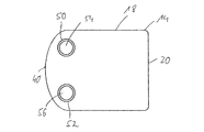
外側のハウジング部分14には、伝熱媒体流動室内に伝熱媒体を供給するために、図2及び図3にも看取可能な2つの伝熱媒体通流管体50,52が設けられている。両伝熱媒体通流管体50,52は、それぞれ、伝熱媒体流動室に連通する開口54,56を形成し、例えば液状の伝熱媒体を伝熱媒体流動室に供給し、伝熱媒体を伝熱媒体流動室から排出するためにそれぞれの管路に接続可能である。その際、両伝熱媒体通流管体50,52は、好ましくは互いに略平行に周方向で間隔を置いて外側周壁18から延在可能である。
In order to supply the heat transfer medium into the heat transfer medium flow chamber, the
両伝熱媒体通流管体50,52は、外側周壁18に、その第1の周方向領域40の領域、つまり外側周壁18が外側底壁20から比較的大きな延在長さを有する領域において設けられている。その際、好ましくは、両伝熱媒体通流管体50,52は、外側周壁18の第1の周方向領域40に、外側周壁18の、ハウジング長手方向軸線Lに関してこの第1の周方向領域40に直径方向で対向する第2の周方向領域42を軸方向で略完全に越えて延在する軸方向の領域において位置している。このことは、外側のハウジング部分14の、図4に示した側面図で見て、両開口54,56に、外側周壁18の、ハウジング長手方向軸線Lに関してこれらの両開口54,56に対向する領域が、軸方向でオーバラップしないことにつながる。これにより、型充填法での外側のハウジング部分14の製造時、開口54,56あるいはこの開口54,56を包囲する伝熱媒体通流管体50,52を形成するために必要な型充填法用の型部品の装入あるいは型充填法による工程の実施後の除去は、極めて容易に実施可能である。
The two heat transfer
両ハウジング部分14,16が組み合わされた状態で、両伝熱媒体通流管体50,52の開口54,56は、熱交換器ハウジング12の、排ガス通流管体30が位置する周方向領域にハウジング長手方向軸線Lに関して対向するか、あるいは直径方向で反対側に位置する周方向領域に位置している。外側のハウジング部分14がその軸方向の端部領域44で斜めに終端しているという事情に基づいて、両伝熱媒体通流管体50,52は、組み合わされた状態で、内側のハウジング部分16に形成された排ガス通流管体30と略同じ軸方向の領域に位置している。ここで、略同じ軸方向の領域とは、伝熱媒体通流管体50,52と排ガス通流管体30とが、軸方向で少なくとも部分的に、好ましくはその軸方向延在長さの大部分で軸方向でオーバラップしていることを意味している。このオーバラップは、伝熱媒体通流管体50,52と排ガス通流管体30とが熱交換器ハウジング12のそれぞれ異なる周方向位置に設けられているという事情に基づいて、問題なく可能である。これにより、熱交換器ハウジング12には、両底壁20,24から軸方向に間隔を置いて、接続領域が形成される。接続領域には、一方では伝熱媒体の供給あるいは排出のための管路が接続可能であり、他方では排ガス案内系の管路が接続可能である。
In a state where both
本発明の構造により、両ハウジング部分14,16をそれぞれ、ハウジング部分14,16と一体的に形成される管体30;50,52を備えて、型充填法で製造することが容易に可能となる。その際、内側のハウジング部分16は、金属ダイカスト法で例えばアルミニウム材料により製造可能である。その結果、排ガス温度が比較的高くても、内側のハウジング部分16を損傷させることはない。温度負荷をそれほど強く受けない外側のハウジング部分14は、プラスチック材料から射出成形法で製造可能である。
According to the structure of the present invention, both the
10 熱交換器アッセンブリ、 12 熱交換器ハウジング、 14 外側のハウジング部分、 16 内側のハウジング部分、 18 外側周壁、 20 外側底壁、 22 内側周壁、 24 内側底壁、 26 内室、 28 端部領域、 30 排ガス通流管体、 32 排ガス出口開口、 34 端面、 36 第1の周方向領域、 38 第2の周方向領域、 40 第1の周方向領域、 42 第2の周方向領域、 44 端部領域、 46,48 結合段部、 50,52 伝熱媒体通流管体、 54,56 開口、 L ハウジング長手方向軸線
10 heat exchanger assembly, 12 heat exchanger housing, 14 outer housing part, 16 inner housing part, 18 outer peripheral wall, 20 outer bottom wall, 22 inner peripheral wall, 24 inner bottom wall, 26 inner chamber, 28
Claims (15)
ハウジング長手方向軸線(L)の方向で延在するカップ状の熱交換器ハウジング(12)を備え、
該熱交換器ハウジング(12)は、外壁(18,20)及び内壁(22,24)を有し、前記外壁(18,20)と前記内壁(22,24)との間に、伝熱媒体流動室が形成されており、前記外壁(18,20)に、前記伝熱媒体流動室に向かって開放された少なくとも1つの伝熱媒体通流管体(50,52)が設けられ、前記熱交換器ハウジング(12)に、該熱交換器ハウジング(12)の、前記内壁(22,24)によって囲繞される内室(26)に向かって開放された排ガス通流管体(30)が設けられており、前記熱交換器ハウジング(12)は、外側周壁(18)及び外側底壁(20)を有する外側のハウジング部分(14)と、内側周壁(22)及び内側底壁(24)を有する内側のハウジング部分(16)とを有する熱交換器アッセンブリにおいて、
少なくとも1つの伝熱媒体通流管体(50,52)は、前記外側のハウジング部分(14)の外側周壁(18)の、前記外側底壁(20)から離れた軸方向の端部領域(44)に設けられており、
前記外側周壁(18)の第1の周方向領域(40)において、前記外側底壁(20)から比較的大きな延在長さを有して前記外側周壁(18)が形成され、かつ前記外側周壁(18)の第2の周方向領域(42)において、前記外側底壁(20)から比較的小さな延在長さを有して前記外側周壁(18)が形成されており、
前記少なくとも1つの伝熱媒体通流管体(50,52)は、前記第1の周方向領域(40)の領域に設けられており、
前記排ガス通流管体(30)は、前記内側のハウジング部分(16)の前記内側周壁(22)の周方向領域であって、前記外側のハウジング部分(14)の前記外側周壁(18)の前記第2の周方向領域(42)に対応し、該第2の周方向領域(42)に軸方向で隣接する周方向領域に設けられていることを特徴とする、熱交換器アッセンブリ、特に車両ヒータ装置用の熱交換器アッセンブリ。 A heat exchanger assembly, in particular a heat exchanger assembly for a vehicle heater device,
A cup-shaped heat exchanger housing (12) extending in the direction of the housing longitudinal axis (L),
The heat exchanger housing (12) has an outer wall (18, 20) and an inner wall (22, 24), and a heat transfer medium is provided between the outer wall (18, 20) and the inner wall (22, 24). A flow chamber is formed, and at least one heat transfer medium flow tube (50, 52) opened toward the heat transfer medium flow chamber is provided on the outer wall (18, 20), and the heat The exchanger housing (12) is provided with an exhaust gas flow tube (30) opened toward the inner chamber (26) surrounded by the inner walls (22, 24) of the heat exchanger housing (12). The heat exchanger housing (12) includes an outer housing part (14) having an outer peripheral wall (18) and an outer bottom wall (20), an inner peripheral wall (22) and an inner bottom wall (24). Heat exchange with inner housing part (16) having In the assembly,
At least one heat transfer medium flow tube (50, 52) is an axial end region (18) of the outer peripheral wall (18) of the outer housing part (14) remote from the outer bottom wall (20). is provided to 44),
In the first circumferential region (40) of the outer peripheral wall (18), the outer peripheral wall (18) is formed with a relatively large extension length from the outer bottom wall (20), and the outer side In the second circumferential region (42) of the peripheral wall (18), the outer peripheral wall (18) is formed with a relatively small extension length from the outer bottom wall (20),
The at least one heat transfer medium flow tube (50, 52) is provided in a region of the first circumferential region (40),
The exhaust gas flow tube (30) is a circumferential region of the inner peripheral wall (22) of the inner housing part (16), and is formed on the outer peripheral wall (18) of the outer housing part (14). A heat exchanger assembly, in particular , provided in a circumferential region corresponding to the second circumferential region (42) and axially adjacent to the second circumferential region (42), Heat exchanger assembly for a vehicle heater device.
請求項1から14までのいずれか1項記載の熱交換器アッセンブリ(10)と、
を備える車両ヒータ装置。 A burner area to be supplied with fuel and combustion air;
The heat exchanger assembly according to any one of claims 1 to 1 4 (10),
A vehicle heater device comprising:
Applications Claiming Priority (2)
| Application Number | Priority Date | Filing Date | Title |
|---|---|---|---|
| DE102012220792.9A DE102012220792A1 (en) | 2012-11-14 | 2012-11-14 | Heat exchanger arrangement, in particular for a vehicle heater |
| DE102012220792.9 | 2012-11-14 |
Publications (2)
| Publication Number | Publication Date |
|---|---|
| JP2014097787A JP2014097787A (en) | 2014-05-29 |
| JP6289875B2 true JP6289875B2 (en) | 2018-03-07 |
Family
ID=49596076
Family Applications (1)
| Application Number | Title | Priority Date | Filing Date |
|---|---|---|---|
| JP2013235906A Active JP6289875B2 (en) | 2012-11-14 | 2013-11-14 | Heat exchanger assembly and vehicle heater device |
Country Status (7)
| Country | Link |
|---|---|
| US (1) | US9616730B2 (en) |
| EP (1) | EP2732996B1 (en) |
| JP (1) | JP6289875B2 (en) |
| CN (1) | CN103808193B (en) |
| DE (1) | DE102012220792A1 (en) |
| PL (1) | PL2732996T3 (en) |
| RU (1) | RU2548219C1 (en) |
Families Citing this family (5)
| Publication number | Priority date | Publication date | Assignee | Title |
|---|---|---|---|---|
| DE102012220792A1 (en) * | 2012-11-14 | 2014-05-15 | Eberspächer Climate Control Systems GmbH & Co. KG | Heat exchanger arrangement, in particular for a vehicle heater |
| WO2015164968A1 (en) | 2014-04-29 | 2015-11-05 | Dana Canada Corporation | Charge air cooler with multi-piece plastic housing |
| EP3910261A1 (en) | 2016-03-30 | 2021-11-17 | Marine Canada Acquisition Inc. | Vehicle heater and controls therefor |
| DE102017112530A1 (en) | 2017-06-07 | 2018-12-13 | Eberspächer Climate Control Systems GmbH & Co. KG | The heat exchanger assembly |
| DE102020100050A1 (en) * | 2020-01-03 | 2021-07-08 | Eberspächer Climate Control Systems GmbH | Heat exchanger housing |
Family Cites Families (68)
| Publication number | Priority date | Publication date | Assignee | Title |
|---|---|---|---|---|
| US540028A (en) * | 1895-05-28 | boeliee | ||
| US2362985A (en) * | 1941-12-24 | 1944-11-21 | Brown Fintube Co | Heat exchanger |
| US2610796A (en) * | 1945-09-28 | 1952-09-16 | Stewart Warner Corp | Thermostatic heater control |
| GB1198869A (en) * | 1967-07-07 | 1970-07-15 | Sueddeutsche Kuehler Behr | Liquid Fuel Operated Heating Apparatus |
| US3894526A (en) * | 1972-10-16 | 1975-07-15 | Eberspaecher J | Space heater construction particularly for mobile installations |
| US3989029A (en) * | 1973-12-11 | 1976-11-02 | Webasto-Werk W. Baier Kg | Liquid fuel burning heater for vehicles |
| US3989030A (en) * | 1974-06-22 | 1976-11-02 | Webasto-Werk W. Baier Kg | Liquid fuel burning heater unit |
| JPS5330545A (en) * | 1976-08-30 | 1978-03-22 | Hitachi Ltd | Automotive preheating heater |
| US4142580A (en) * | 1976-11-19 | 1979-03-06 | Phillips Petroleum Company | Bayonet heat exchanger having means for positioning bayonet tube in sheath tube |
| DE2718215A1 (en) * | 1977-04-23 | 1978-11-02 | Webasto Werk Baier Kg W | ADDITIONAL HEATER FOR VEHICLES |
| DE2931936C2 (en) * | 1979-08-07 | 1985-10-17 | Webasto-Werk W. Baier GmbH & Co, 8035 Gauting | Heater operated with flowable fuel |
| DE3010078C2 (en) * | 1980-03-15 | 1982-10-07 | Webasto-Werk W. Baier GmbH & Co, 8035 Gauting | Liquid fuel burners for heating devices |
| DE3248412C2 (en) * | 1982-12-28 | 1985-11-21 | Webasto-Werk W. Baier GmbH & Co, 8035 Gauting | Heater fed with flowable fuel |
| DE3337601A1 (en) * | 1983-10-15 | 1985-04-25 | Webasto-Werk W. Baier GmbH & Co, 8035 Gauting | HEATER, ESPECIALLY VEHICLE HEATER |
| DE3341490A1 (en) | 1983-11-17 | 1985-05-30 | Webasto-Werk W. Baier GmbH & Co, 8035 Gauting | FUEL-OPERATED HEATING DEVICE, IN PARTICULAR VEHICLE ACCESSORY HEATING DEVICE |
| DE3400048A1 (en) * | 1984-01-03 | 1985-07-11 | Webasto-Werk W. Baier GmbH & Co, 8035 Gauting | WATER HEATER |
| DE3416878A1 (en) * | 1984-05-08 | 1985-11-14 | Webasto-Werk W. Baier GmbH & Co, 8035 Gauting | HEATING UNIT, ESPECIALLY VEHICLE ADDITIONAL HEATING UNIT |
| JPS61188216A (en) * | 1985-02-15 | 1986-08-21 | Isuzu Motors Ltd | Heat exchanger for car heater |
| CA1282315C (en) | 1985-10-10 | 1991-04-02 | Bernhard Umlauf | Fuel operated vehicle heater |
| JPS62293087A (en) * | 1986-06-10 | 1987-12-19 | Isuzu Motors Ltd | Heat exchanger |
| JPS62293088A (en) * | 1986-06-10 | 1987-12-19 | Isuzu Motors Ltd | Heat exchanger |
| JPS62294847A (en) * | 1986-06-13 | 1987-12-22 | Isuzu Motors Ltd | Heating device |
| JPS6396493A (en) * | 1986-10-07 | 1988-04-27 | Isuzu Motors Ltd | Heat exchanger |
| JPS6396491A (en) * | 1986-10-07 | 1988-04-27 | Isuzu Motors Ltd | Heat exchanger |
| EP0287923A3 (en) * | 1987-04-22 | 1990-03-21 | Webasto AG Fahrzeugtechnik | Heater, particularly an additional heater for vehicles |
| DE3807190A1 (en) * | 1988-03-04 | 1989-09-14 | Webasto Ag Fahrzeugtechnik | Heating apparatus, in particular vehicle heating apparatus |
| US5219535A (en) * | 1988-11-10 | 1993-06-15 | Mannesmann Ag | Heating an endothermic process |
| DE3839243C2 (en) * | 1988-11-21 | 1997-03-20 | Webasto Ag Fahrzeugtechnik | Silencers for heaters |
| RU2015035C1 (en) * | 1989-03-07 | 1994-06-30 | Й.Эбершпэхер | Vehicle heating device |
| JPH0379424A (en) * | 1989-08-23 | 1991-04-04 | Isuzu Ceramics Kenkyusho:Kk | Heat exchanger of heater |
| KR910012551A (en) * | 1989-09-14 | 1991-08-08 | 이다가끼 유끼오 | air blower |
| IT1235742B (en) * | 1989-09-29 | 1992-09-24 | Rossi & Catelli Spa | HEAT EXCHANGER FOR TOMATO |
| JPH08580Y2 (en) * | 1989-11-16 | 1996-01-10 | 株式会社ゼクセル | Combustion heating system |
| US5205250A (en) * | 1991-12-06 | 1993-04-27 | Herbert Easterly | Fuel preheating system |
| US5542467A (en) * | 1993-07-06 | 1996-08-06 | Societe E'etudes Et De Constructions Aero-Navales | Safety annular heat exchanger for incompatible fluids |
| DE4446829B4 (en) * | 1993-12-31 | 2005-01-13 | J. Eberspächer GmbH & Co. KG | Vehicle heater with overheat monitor |
| JPH08188040A (en) * | 1995-01-12 | 1996-07-23 | Nippon Soken Inc | Combustion heater |
| DE19509780C1 (en) * | 1995-03-17 | 1996-08-14 | Webasto Thermosysteme Gmbh | Heating unit for vehicle |
| DE19524260C5 (en) * | 1995-07-04 | 2005-11-17 | J. Eberspächer GmbH & Co. KG | Heater, in particular for heating the interior of a motor vehicle |
| DE19538947C2 (en) * | 1995-10-19 | 1998-11-26 | Webasto Thermosysteme Gmbh | Vehicle heater |
| US6082625A (en) * | 1996-07-29 | 2000-07-04 | Teleflex (Canada) Ltd. | Transit vehicle heater |
| DE19724502C1 (en) * | 1997-06-11 | 1998-10-08 | Webasto Thermosysteme Gmbh | Auxiliary heating device for motor vehicle |
| DE19749821C1 (en) | 1997-11-11 | 1999-03-18 | Webasto Thermosysteme Gmbh | Combustion heater for motor vehicle |
| FR2779812B1 (en) * | 1998-06-12 | 2000-10-06 | Soc Et Et De Const Aero Navale | HEAT EXCHANGER OF THE HOLLOW CASING TYPE INCLUDING IN PARTICULAR A LARGE NUMBER OF FIRST FLOW WAYS OF A FIRST FLUID AND TRAVELED BY A SECOND FLUID IN THERMAL EXCHANGE CONTACT WITH THESE WAYS |
| JP2001330212A (en) * | 2000-05-22 | 2001-11-30 | Denso Corp | Combustion heater |
| DE10051755C1 (en) * | 2000-10-18 | 2002-04-18 | Webasto Thermosysteme Gmbh | Heat exchanger for motor vehicle's auxiliary heater has overheat protection sensor installed in outwards orientated boss formed on heat exchanger's inner section and which fits in sealed opening in outer section |
| DE10063922C1 (en) * | 2000-12-20 | 2002-07-18 | Webasto Thermosysteme Gmbh | Heater, for vehicle, includes protective device with heat carrier mass flow meter to protect immediately against overheating |
| JP2002205531A (en) * | 2001-01-11 | 2002-07-23 | Denso Corp | Combustion heater |
| JP2002331821A (en) * | 2001-05-09 | 2002-11-19 | Denso Corp | Combustion type heater |
| DE10143458B4 (en) * | 2001-09-05 | 2008-09-25 | Webasto Ag | Additional heater with a heat exchanger |
| DE10143479C1 (en) | 2001-09-05 | 2003-01-30 | Webasto Thermosysteme Gmbh | Auxiliary heating device for mobile applications has struts between inner dish and outer dish of heat exchanger for flow deflection and heat energy transfer |
| DE10200962A1 (en) * | 2002-01-12 | 2003-07-31 | Eberspaecher J Gmbh & Co | Heater and housing for a heater |
| DE10207953B4 (en) | 2002-02-25 | 2005-05-25 | J. Eberspächer GmbH & Co. KG | Heater, in particular for a vehicle |
| DE10261966B4 (en) * | 2002-03-15 | 2005-08-25 | J. Eberspächer GmbH & Co. KG | Air heater for integration into an air-conducting housing arrangement |
| DE10226081B4 (en) * | 2002-06-12 | 2005-11-03 | J. Eberspächer GmbH & Co. KG | The heat exchanger assembly |
| DE10227626A1 (en) * | 2002-06-20 | 2004-01-15 | J. Eberspächer GmbH & Co. KG | Heating device, in particular for a vehicle |
| US6896037B2 (en) * | 2002-10-29 | 2005-05-24 | Duramax Marine, Llc | Keel cooler with fluid flow diverter |
| JP2004268886A (en) * | 2003-03-12 | 2004-09-30 | Denso Corp | Heat-exchanger control device |
| DE102005053514A1 (en) * | 2004-11-26 | 2006-07-06 | Webasto Ag | Air heater for a motor vehicle |
| DE102005001662A1 (en) * | 2005-01-13 | 2006-07-27 | J. Eberspächer GmbH & Co. KG | Heat exchanger body and vehicle heater with a heat exchanger body |
| CN200984956Y (en) * | 2006-12-15 | 2007-12-05 | 山东大学 | Small-sized liquid heating fuel heater with adjustable air-fuel ratio |
| DE102009055686A1 (en) * | 2009-11-25 | 2011-05-26 | Webasto Ag | Heat exchanger for a mobile heater, mobile heater and motor vehicle |
| DE102011004159A1 (en) | 2011-02-15 | 2012-08-16 | J. Eberspächer GmbH & Co. KG | Heat exchanger arrangement, in particular for a fuel-powered vehicle heater |
| RU112099U1 (en) * | 2011-05-12 | 2012-01-10 | Ольга Николаевна Жаркова | HEATING DEVICE (OPTIONS) |
| DE102011079018A1 (en) * | 2011-07-12 | 2013-01-17 | J. Eberspächer GmbH & Co. KG | vehicle heater |
| DE102011081401B4 (en) * | 2011-08-23 | 2015-09-10 | Eberspächer Climate Control Systems GmbH & Co. KG | Heat exchanger arrangement, in particular for a fuel-powered vehicle heater |
| DE102012220792A1 (en) * | 2012-11-14 | 2014-05-15 | Eberspächer Climate Control Systems GmbH & Co. KG | Heat exchanger arrangement, in particular for a vehicle heater |
| DE102012220789B4 (en) * | 2012-11-14 | 2021-06-24 | Eberspächer Climate Control Systems GmbH | Heat exchanger arrangement, in particular for a vehicle heater |
-
2012
- 2012-11-14 DE DE102012220792.9A patent/DE102012220792A1/en not_active Withdrawn
-
2013
- 2013-11-12 PL PL13192453T patent/PL2732996T3/en unknown
- 2013-11-12 EP EP13192453.2A patent/EP2732996B1/en active Active
- 2013-11-13 RU RU2013150635/06A patent/RU2548219C1/en active
- 2013-11-13 US US14/078,888 patent/US9616730B2/en active Active
- 2013-11-14 CN CN201310757291.4A patent/CN103808193B/en active Active
- 2013-11-14 JP JP2013235906A patent/JP6289875B2/en active Active
Also Published As
| Publication number | Publication date |
|---|---|
| RU2013150635A (en) | 2015-05-20 |
| JP2014097787A (en) | 2014-05-29 |
| RU2548219C1 (en) | 2015-04-20 |
| DE102012220792A1 (en) | 2014-05-15 |
| US9616730B2 (en) | 2017-04-11 |
| EP2732996B1 (en) | 2015-06-17 |
| CN103808193B (en) | 2016-02-24 |
| CN103808193A (en) | 2014-05-21 |
| PL2732996T3 (en) | 2015-11-30 |
| EP2732996A1 (en) | 2014-05-21 |
| US20140131461A1 (en) | 2014-05-15 |
Similar Documents
| Publication | Publication Date | Title |
|---|---|---|
| JP6289875B2 (en) | Heat exchanger assembly and vehicle heater device | |
| JP4878287B2 (en) | Heat exchanger | |
| CN110260520A (en) | Heat exchange unit for heating boiler | |
| JP2009506287A (en) | Exhaust gas heat exchanger | |
| KR101394037B1 (en) | Exhaust gas exhaust system | |
| KR20180101498A (en) | Cooling panels for combustor panels, combustors, combustion devices, gas turbines, and combustor panels | |
| CN102654073A (en) | Exhaust heat recovery device | |
| ITTO20110446A1 (en) | HEAT EXCHANGER AND IMPLEMENTATION PROCEDURE | |
| CN105298630A (en) | Supercharger | |
| CN102642455B (en) | Heat exchange rig | |
| WO2016088489A1 (en) | Exhaust heat recovery device | |
| US10465942B2 (en) | Integrated water heater | |
| JP2004217017A (en) | Piping for heater, joint and connecting structure between piping for heater and joint | |
| JP4110284B2 (en) | A heater having an exhaust port coupling portion coupled to a heat exchanger | |
| US20060151623A1 (en) | Heat exchanger body and vehicle heater with a heat exchanger body | |
| JP2016070655A (en) | Heat exchanger | |
| RU2548966C1 (en) | Heat exchanger, particularly for vehicle heater | |
| CN110722958B (en) | Vehicle heating apparatus | |
| KR20170107439A (en) | Heat exchanger | |
| KR20100060864A (en) | Heat exchanger | |
| JP5225804B2 (en) | Boiler and heat recovery device | |
| CN201331168Y (en) | Coil burning device for hot water cleaning machine | |
| JP2005299998A (en) | Cylindrical burner | |
| JP2019128056A (en) | Cylindrical heat exchanger | |
| JP2014214924A (en) | Latent heat exchanger |
Legal Events
| Date | Code | Title | Description |
|---|---|---|---|
| A621 | Written request for application examination |
Free format text: JAPANESE INTERMEDIATE CODE: A621 Effective date: 20160706 |
|
| A977 | Report on retrieval |
Free format text: JAPANESE INTERMEDIATE CODE: A971007 Effective date: 20170714 |
|
| A131 | Notification of reasons for refusal |
Free format text: JAPANESE INTERMEDIATE CODE: A131 Effective date: 20170724 |
|
| A521 | Request for written amendment filed |
Free format text: JAPANESE INTERMEDIATE CODE: A523 Effective date: 20171024 |
|
| TRDD | Decision of grant or rejection written | ||
| A01 | Written decision to grant a patent or to grant a registration (utility model) |
Free format text: JAPANESE INTERMEDIATE CODE: A01 Effective date: 20180109 |
|
| A61 | First payment of annual fees (during grant procedure) |
Free format text: JAPANESE INTERMEDIATE CODE: A61 Effective date: 20180207 |
|
| R150 | Certificate of patent or registration of utility model |
Ref document number: 6289875 Country of ref document: JP Free format text: JAPANESE INTERMEDIATE CODE: R150 |
|
| S533 | Written request for registration of change of name |
Free format text: JAPANESE INTERMEDIATE CODE: R313533 |
|
| R350 | Written notification of registration of transfer |
Free format text: JAPANESE INTERMEDIATE CODE: R350 |
|
| R250 | Receipt of annual fees |
Free format text: JAPANESE INTERMEDIATE CODE: R250 |
|
| R250 | Receipt of annual fees |
Free format text: JAPANESE INTERMEDIATE CODE: R250 |
|
| R250 | Receipt of annual fees |
Free format text: JAPANESE INTERMEDIATE CODE: R250 |
|
| R250 | Receipt of annual fees |
Free format text: JAPANESE INTERMEDIATE CODE: R250 |