JP6289859B2 - Trap apparatus and substrate processing apparatus - Google Patents
Trap apparatus and substrate processing apparatus Download PDFInfo
- Publication number
- JP6289859B2 JP6289859B2 JP2013218718A JP2013218718A JP6289859B2 JP 6289859 B2 JP6289859 B2 JP 6289859B2 JP 2013218718 A JP2013218718 A JP 2013218718A JP 2013218718 A JP2013218718 A JP 2013218718A JP 6289859 B2 JP6289859 B2 JP 6289859B2
- Authority
- JP
- Japan
- Prior art keywords
- trap
- downstream
- upstream
- opening
- gas flow
- Prior art date
- Legal status (The legal status is an assumption and is not a legal conclusion. Google has not performed a legal analysis and makes no representation as to the accuracy of the status listed.)
- Active
Links
Images


Classifications
-
- B—PERFORMING OPERATIONS; TRANSPORTING
- B01—PHYSICAL OR CHEMICAL PROCESSES OR APPARATUS IN GENERAL
- B01D—SEPARATION
- B01D46/00—Filters or filtering processes specially modified for separating dispersed particles from gases or vapours
- B01D46/56—Filters or filtering processes specially modified for separating dispersed particles from gases or vapours with multiple filtering elements, characterised by their mutual disposition
- B01D46/62—Filters or filtering processes specially modified for separating dispersed particles from gases or vapours with multiple filtering elements, characterised by their mutual disposition connected in series
-
- C—CHEMISTRY; METALLURGY
- C23—COATING METALLIC MATERIAL; COATING MATERIAL WITH METALLIC MATERIAL; CHEMICAL SURFACE TREATMENT; DIFFUSION TREATMENT OF METALLIC MATERIAL; COATING BY VACUUM EVAPORATION, BY SPUTTERING, BY ION IMPLANTATION OR BY CHEMICAL VAPOUR DEPOSITION, IN GENERAL; INHIBITING CORROSION OF METALLIC MATERIAL OR INCRUSTATION IN GENERAL
- C23C—COATING METALLIC MATERIAL; COATING MATERIAL WITH METALLIC MATERIAL; SURFACE TREATMENT OF METALLIC MATERIAL BY DIFFUSION INTO THE SURFACE, BY CHEMICAL CONVERSION OR SUBSTITUTION; COATING BY VACUUM EVAPORATION, BY SPUTTERING, BY ION IMPLANTATION OR BY CHEMICAL VAPOUR DEPOSITION, IN GENERAL
- C23C16/00—Chemical coating by decomposition of gaseous compounds, without leaving reaction products of surface material in the coating, i.e. chemical vapour deposition [CVD] processes
- C23C16/44—Chemical coating by decomposition of gaseous compounds, without leaving reaction products of surface material in the coating, i.e. chemical vapour deposition [CVD] processes characterised by the method of coating
- C23C16/4412—Details relating to the exhausts, e.g. pumps, filters, scrubbers, particle traps
-
- H—ELECTRICITY
- H01—ELECTRIC ELEMENTS
- H01J—ELECTRIC DISCHARGE TUBES OR DISCHARGE LAMPS
- H01J37/00—Discharge tubes with provision for introducing objects or material to be exposed to the discharge, e.g. for the purpose of examination or processing thereof
- H01J37/32—Gas-filled discharge tubes
- H01J37/32431—Constructional details of the reactor
- H01J37/32798—Further details of plasma apparatus not provided for in groups H01J37/3244 - H01J37/32788; special provisions for cleaning or maintenance of the apparatus
- H01J37/32816—Pressure
- H01J37/32834—Exhausting
- H01J37/32844—Treating effluent gases
-
- Y—GENERAL TAGGING OF NEW TECHNOLOGICAL DEVELOPMENTS; GENERAL TAGGING OF CROSS-SECTIONAL TECHNOLOGIES SPANNING OVER SEVERAL SECTIONS OF THE IPC; TECHNICAL SUBJECTS COVERED BY FORMER USPC CROSS-REFERENCE ART COLLECTIONS [XRACs] AND DIGESTS
- Y02—TECHNOLOGIES OR APPLICATIONS FOR MITIGATION OR ADAPTATION AGAINST CLIMATE CHANGE
- Y02C—CAPTURE, STORAGE, SEQUESTRATION OR DISPOSAL OF GREENHOUSE GASES [GHG]
- Y02C20/00—Capture or disposal of greenhouse gases
- Y02C20/30—Capture or disposal of greenhouse gases of perfluorocarbons [PFC], hydrofluorocarbons [HFC] or sulfur hexafluoride [SF6]
-
- Y—GENERAL TAGGING OF NEW TECHNOLOGICAL DEVELOPMENTS; GENERAL TAGGING OF CROSS-SECTIONAL TECHNOLOGIES SPANNING OVER SEVERAL SECTIONS OF THE IPC; TECHNICAL SUBJECTS COVERED BY FORMER USPC CROSS-REFERENCE ART COLLECTIONS [XRACs] AND DIGESTS
- Y02—TECHNOLOGIES OR APPLICATIONS FOR MITIGATION OR ADAPTATION AGAINST CLIMATE CHANGE
- Y02P—CLIMATE CHANGE MITIGATION TECHNOLOGIES IN THE PRODUCTION OR PROCESSING OF GOODS
- Y02P70/00—Climate change mitigation technologies in the production process for final industrial or consumer products
- Y02P70/50—Manufacturing or production processes characterised by the final manufactured product
Description
本発明の種々の側面及び実施形態は、トラップ装置及び基板処理装置に関するものである。 Various aspects and embodiments of the present invention relate to a trap apparatus and a substrate processing apparatus.
半導体の製造プロセスでは、薄膜の堆積又はエッチング等を目的としたプラズマ処理を実行する基板処理装置が広く用いられている。基板処理装置としては、例えば薄膜の堆積処理を行うプラズマCVD(Chemical Vapor Deposition)装置や、エッチング処理を行うプラズマエッチング装置等のプラズマ処理装置が挙げられる。 In semiconductor manufacturing processes, substrate processing apparatuses that perform plasma processing for the purpose of thin film deposition or etching are widely used. Examples of the substrate processing apparatus include a plasma processing apparatus such as a plasma CVD (Chemical Vapor Deposition) apparatus that performs a thin film deposition process and a plasma etching apparatus that performs an etching process.
基板処理装置は、例えば、被処理基板をプラズマ処理するための処理容器、処理容器の内部を減圧するための排気装置、及び、処理容器と排気装置とを接続する排気流路等を備える。 The substrate processing apparatus includes, for example, a processing container for plasma-processing a substrate to be processed, an exhaust device for decompressing the inside of the processing container, and an exhaust channel connecting the processing container and the exhaust device.
ところで、基板処理装置においては、排気流路を通流する気体流に処理容器内のプラズマ反応によって生じた反応生成物が含まれるので、気体流から反応生成物を除去することが望まれる。この点、特許文献1には、排気流路に接続された外側筒状部材に内側筒状部材を設置するとともに、内側筒状部材の下流側開口を塞ぐようにメッシュ状のトラップ媒体を配置し、トラップ媒体を用いて気体流中の反応生成物を捕捉する構造が開示されている。
By the way, in the substrate processing apparatus, since the reaction product generated by the plasma reaction in the processing container is included in the gas flow flowing through the exhaust passage, it is desired to remove the reaction product from the gas flow. In this regard, in
しかしながら、従来の構造のように、内側筒状部材の下流側開口を塞ぐようにメッシュ状のトラップ媒体を配置するだけでは、気体流に含まれる反応生成物を効率良く除去することが困難である。 However, it is difficult to efficiently remove reaction products contained in the gas flow simply by disposing the mesh trap medium so as to close the downstream opening of the inner cylindrical member as in the conventional structure. .
本発明の一側面に係るトラップ装置は、空間を有する第1の筒状部材と、前記空間に着脱自在に配置され、気体流を流入させる上流側開口と、前記上流側開口から流入される前記気体流を流出させる下流側開口とを有する第2の筒状部材と、前記下流側開口を塞ぐように前記第2の筒状部材の内部に配置された下流側トラップ部材と、前記下流側トラップ部材と、前記第2の筒状部材の前記上流側開口との間に配置され、前記下流側トラップ部材に近づく向きに凹む凹部を有する上流側トラップ部材とを備えた。 The trap device according to an aspect of the present invention is a first cylindrical member having a space, an upstream opening that is detachably disposed in the space, and allows a gas flow to flow in, and the inflow from the upstream opening. A second cylindrical member having a downstream opening for allowing a gas flow to flow out; a downstream trap member disposed inside the second cylindrical member so as to close the downstream opening; and the downstream trap. And an upstream trap member having a recess that is disposed between the member and the upstream opening of the second tubular member and is recessed toward the downstream trap member.
本発明の種々の側面及び実施形態によれば、気体流に含まれる反応生成物を効率良く除去することができるトラップ装置及び基板処理装置が実現される。 According to various aspects and embodiments of the present invention, a trap device and a substrate processing apparatus that can efficiently remove reaction products contained in a gas flow are realized.
以下、図面を参照して開示するトラップ装置及び基板処理装置について詳細に説明する。なお、各図面において同一又は相当の部分に対しては同一の符号を附すこととする。また、以下では、本願の開示する基板処理装置を、例えば薄膜の堆積処理を行うプラズマCVD(Chemical Vapor Deposition)装置や、エッチング処理を行うプラズマエッチング装置等のプラズマ処理装置に適用する例について説明する。 Hereinafter, a trap apparatus and a substrate processing apparatus disclosed with reference to the drawings will be described in detail. In the drawings, the same or corresponding parts are denoted by the same reference numerals. Hereinafter, an example in which the substrate processing apparatus disclosed in the present application is applied to a plasma processing apparatus such as a plasma CVD (Chemical Vapor Deposition) apparatus that performs a thin film deposition process or a plasma etching apparatus that performs an etching process will be described. .
開示するトラップ装置は、1つの実施形態において、空間を有する第1の筒状部材と、空間に着脱自在に配置され、気体流を流入させる上流側開口と、上流側開口から流入される気体流を流出させる下流側開口とを有する第2の筒状部材と、下流側開口を塞ぐように第2の筒状部材の内部に配置された下流側トラップ部材と、下流側トラップ部材と、第2の筒状部材の上流側開口との間に配置され、下流側トラップ部材に近づく向きに凹む凹部を有する上流側トラップ部材とを備えた。 In one embodiment, the disclosed trap device includes a first cylindrical member having a space, an upstream opening that is detachably disposed in the space, and a gas flow that flows in from the upstream opening. A second cylindrical member having a downstream opening for flowing out, a downstream trap member disposed inside the second cylindrical member so as to close the downstream opening, a downstream trap member, and a second And an upstream trap member having a recess recessed in a direction approaching to the downstream trap member.
開示するトラップ装置は、1つの実施形態において、上流側トラップ部材は、凹部の径が下流側トラップ部材に近づく向きに沿って小さくなる形状に形成される。 In one embodiment of the disclosed trap device, the upstream trap member is formed in a shape in which the diameter of the recess decreases along the direction approaching the downstream trap member.
開示するトラップ装置は、1つの実施形態において、上流側トラップ部材は、下流側トラップ部材に近づく向きに尖る円錐形状に形成される。 In one embodiment of the disclosed trap apparatus, the upstream trap member is formed in a conical shape that is pointed toward the downstream trap member.
開示するトラップ装置は、1つの実施形態において、上流側トラップ部材は、下流側トラップ部材に近づく向きに沿って、下流側トラップ部材と、第2の筒状部材の上流側開口との間に複数配置される。 In one embodiment, the disclosed trap apparatus includes a plurality of upstream trap members between the downstream trap member and the upstream opening of the second tubular member along a direction approaching the downstream trap member. Be placed.
開示するトラップ装置は、1つの実施形態において、複数の上流側トラップ部材の各々は、気体流を通過させる貫通孔を含み、貫通孔の密度及び径の少なくともいずれか一方が複数の上流側トラップ部材の間で異なる。 In one embodiment of the disclosed trap apparatus, each of the plurality of upstream trap members includes a through hole through which a gas flow passes, and at least one of the density and the diameter of the through holes has a plurality of upstream trap members. Different between.
開示する基板処理装置は、1つの実施形態において、被処理基板を処理するための処理容器と、処理容器の内部を減圧するための排気装置と、処理容器と排気装置とを接続する排気流路と、排気流路に設けられたトラップ装置とを備えた基板処理装置であって、トラップ装置は、空間を有する第1の筒状部材と、空間に着脱自在に配置され、気体流を流入させる上流側開口と、上流側開口から流入される気体流を流出させる下流側開口とを有する第2の筒状部材と、下流側開口を塞ぐように第2の筒状部材の内部に配置された下流側トラップ部材と、下流側トラップ部材と、第2の筒状部材の上流側開口との間に配置され、下流側トラップ部材に近づく向きに凹む凹部を有する上流側トラップ部材とを備えた。 In one embodiment of the disclosed substrate processing apparatus, a processing container for processing a substrate to be processed, an exhaust device for decompressing the inside of the processing container, and an exhaust flow path connecting the processing container and the exhaust device And a trap device provided in the exhaust flow path, the trap device being detachably disposed in the space and a first cylindrical member having a space, and allowing a gas flow to flow in A second cylindrical member having an upstream opening, a downstream opening for discharging a gas flow flowing in from the upstream opening, and the second cylindrical member disposed inside the second cylindrical member so as to close the downstream opening. The downstream trap member, the downstream trap member, and the upstream trap member having a recess that is disposed between the upstream opening of the second tubular member and recessed toward the downstream trap member.
まず、プラズマ処理装置の全体構成について説明する。図1は、一実施形態に係るプラズマ処理装置の構成の概略を示す縦断面図である。 First, the overall configuration of the plasma processing apparatus will be described. FIG. 1 is a longitudinal sectional view showing an outline of a configuration of a plasma processing apparatus according to an embodiment.
プラズマ処理装置は、気密に構成され、電気的に接地電位とされた処理チャンバー(処理容器)1を有している。この処理チャンバー1は、円筒状とされ、例えばアルミニウム等から構成されており、プラズマ処理を行うためのプラズマ処理空間を画成している。処理チャンバー1内には、被処理基板である半導体ウエハWが載置される下部電極2が設けられている。下部電極2は、その基材2aが導電性の金属、例えばアルミニウム等で構成されている。この下部電極2は、絶縁板3を介して導体の支持台4に支持されている。下部電極2及び支持台4の周囲を囲むように、例えば石英等からなる円筒状の内壁部材3aが設けられている。
The plasma processing apparatus includes a processing chamber (processing container) 1 that is airtight and is electrically grounded. The
下部電極2の基材2aには、第1の整合器11aを介して第1のRF電源10aが接続され、また、第2の整合器11bを介して第2のRF電源10bが接続されている。第1のRF電源10aは、プラズマ発生用のものであり、この第1のRF電源10aからは所定周波数(27MHz以上例えば40MHz)の高周波電力が下部電極2の基材2aに供給されるようになっている。また、第2のRF電源10bは、イオン引き込み用(バイアス用)のものであり、この第2のRF電源10bからは第1のRF電源10aより低い所定周波数(13.56MHz以下、例えば3.2MHz)の高周波電力が下部電極2の基材2aに供給されるようになっている。
A first
下部電極2の上方には、処理チャンバー1のプラズマ処理空間を介して下部電極2と対向するように、上部電極16が設けられている。上部電極16と下部電極2とは、一対の電極として機能するようになっている。上部電極16と下部電極2との間の空間がプラズマを生成させるためのプラズマ処理空間となる。
An
支持台4の内部には、冷媒流路4aが形成されており、冷媒流路4aには、冷媒入口配管4b、冷媒出口配管4cが接続されている。そして、冷媒流路4aの中に適宜の冷媒、例えば冷却水等を循環させることによって、支持台4及び下部電極2を所定の温度に制御可能となっている。また、下部電極2等を貫通するように、半導体ウエハWの裏面側にヘリウムガス等の冷熱伝達用ガス(バックサイドガス)を供給するためのバックサイドガス供給配管30が設けられており、このバックサイドガス供給配管30は、図示しないバックサイドガス供給源に接続されている。これらの構成によって、下部電極2の上面に載置された半導体ウエハWを、所定の温度に制御可能となっている。
A
上部電極16は、処理チャンバー1の天壁部分に設けられている。上部電極16は、本体部16aと電極板をなす上部天板16bとを備えており、絶縁性部材45を介して処理チャンバー1の上部に支持されている。本体部16aは、導電性材料、例えば表面が陽極酸化処理されたアルミニウムからなり、その下部に上部天板16bを着脱自在に支持できるように構成されている。
The
本体部16aの内部には、ガス拡散室16cが設けられ、このガス拡散室16cの下部に位置するように、本体部16aの底部には、多数のガス通流孔16dが形成されている。また、上部天板16bには、当該上部天板16bを厚さ方向に貫通するようにガス導入孔16eが、上記したガス通流孔16dと重なるように設けられている。このような構成により、ガス拡散室16cに供給された処理ガスは、ガス通流孔16d及びガス導入孔16eを介して処理チャンバー1内にシャワー状に分散されて供給されるようになっている。なお、本体部16a等には、冷媒を循環させるための図示しない配管が設けられており、プラズマエッチング処理中に上部電極16を所望温度に冷却できるようになっている。
A
本体部16aには、ガス拡散室16cへ処理ガスを導入するためのガス導入口16fが形成されている。このガス導入口16fにはガス供給配管15aが接続されており、このガス供給配管15aの他端には、エッチング用の処理ガスを供給する処理ガス供給源15が接続されている。ガス供給配管15aには、上流側から順にマスフローコントローラ(MFC)15b、及び開閉弁V1が設けられている。そして、処理ガス供給源15からプラズマエッチングのための処理ガスが、ガス供給配管15aを介してガス拡散室16cに供給され、このガス拡散室16cから、ガス通流孔16d及びガス導入孔16eを介して処理チャンバー1内にシャワー状に分散されて供給される。
A
上部電極16には、ローパスフィルタ(LPF)51を介して可変直流電源52が電気的に接続されている。この可変直流電源52は、オン・オフスイッチ53により給電のオン・オフが可能となっている。可変直流電源52の電流・電圧ならびにオン・オフスイッチ53のオン・オフは、後述するコントローラ60によって制御されるようになっている。なお、後述のように、第1のRF電源10a、第2のRF電源10bから高周波が下部電極2に印加されてプラズマ処理空間にプラズマが発生する際には、必要に応じてコントローラ60によりオン・オフスイッチ53がオンとされ、上部電極16に所定の直流電圧が印加される。
A variable
処理チャンバー1の側壁から上部電極16の高さ位置よりも上方に延びるように円筒状の接地導体1aが設けられている。この円筒状の接地導体1aは、その上部に天壁を有している。
A
処理チャンバー1の底部には、排気口71が形成されており、この排気口71には、排気管72を介して排気装置73が接続されている。排気管72は、処理チャンバー1と排気装置73とを接続する排気流路である。排気装置73は、真空ポンプを有しており、この真空ポンプを作動させることにより処理チャンバー1内を所定の真空度まで減圧することができるようになっている。処理チャンバー1内のプラズマ反応によって生じた生成物(以下「反応生成物」という)は、排気装置73によって処理チャンバー1内が減圧されることによって、気体流と共に排気管72を通流する。
An
また、排気管72には、排気管72を通流する気体流から反応生成物を除去するためのトラップ装置100が設けられている。トラップ装置100の詳細な構成については、後述する。
The
一方、処理チャンバー1の側壁には、半導体ウエハWの搬入出口74が設けられており、この搬入出口74には、当該搬入出口74を開閉するゲートバルブ75が設けられている。
On the other hand, a loading / unloading
図中76,77は、着脱自在とされたデポシールドである。デポシールド76は、処理チャンバー1の内壁面に沿って設けられ、処理チャンバー1にエッチング副生物(デポ)が付着することを防止する役割を有し、このデポシールド76の半導体ウエハWと略同じ高さ位置には、直流的にグランドに接続された導電性部材(GNDブロック)79が設けられており、これにより異常放電が防止される。
In the figure,
上記構成のプラズマ処理装置は、コントローラ60によって、その動作が統括的に制御される。コントローラ60には、CPUを備えプラズマ処理装置の各部を制御するプロセスコントローラと、ユーザインターフェースと、記憶部とが設けられている。 The operation of the plasma processing apparatus having the above configuration is comprehensively controlled by the controller 60. The controller 60 includes a process controller that includes a CPU and controls each unit of the plasma processing apparatus, a user interface, and a storage unit.
コントローラ60のユーザインターフェースは、工程管理者がプラズマエッチング装置を管理するためにコマンドの入力操作を行うキーボードや、プラズマエッチング装置の稼働状況を可視化して表示するディスプレイ等から構成されている。 The user interface of the controller 60 is composed of a keyboard on which a process manager inputs commands to manage the plasma etching apparatus, a display that visualizes and displays the operating status of the plasma etching apparatus, and the like.
コントローラ60の記憶部には、プラズマエッチング装置で実行される各種処理をプロセスコントローラの制御にて実現するための制御プログラム(ソフトウエア)や処理条件データ等が記憶されたレシピが格納されている。そして、必要に応じて、コントローラ60のユーザインターフェースからの指示等にて任意のレシピを記憶部から呼び出してプロセスコントローラに実行させることで、コントローラ60のプロセスコントローラの制御下で、プラズマエッチング装置での所望の処理が行われる。また、制御プログラムや処理条件データ等のレシピは、コンピュータで読取り可能なコンピュータ記憶媒体(例えば、ハードディスク、CD、フレキシブルディスク、半導体メモリ等)などに格納された状態のものを利用したり、或いは、他の装置から、例えば専用回線を介して随時伝送させてオンラインで利用したりすることも可能である。 The storage unit of the controller 60 stores a recipe in which a control program (software) for realizing various processes executed by the plasma etching apparatus under the control of the process controller, processing condition data, and the like are stored. Then, if necessary, an arbitrary recipe is called from the storage unit by an instruction from the user interface of the controller 60 and is executed by the process controller, so that the process in the plasma etching apparatus is performed under the control of the process controller of the controller 60. Desired processing is performed. In addition, recipes such as control programs and processing condition data may be stored in a computer-readable computer storage medium (eg, hard disk, CD, flexible disk, semiconductor memory, etc.), or It is also possible to transmit the data from other devices as needed via a dedicated line and use it online.
次に、排気管72に設けられたトラップ装置100の詳細な構成について説明する。図2は、一実施形態におけるトラップ装置の詳細な構成を示す断面図である。図2の説明では、トラップ装置100よりも処理チャンバー1の排気口71側に位置する排気管72を「上流側の排気管72」と呼び、トラップ装置100よりも排気装置73側に位置する排気管72を「下流側の排気管72」と呼ぶものとする。
Next, a detailed configuration of the
図2に示すように、トラップ装置100は、内部空間Sを有する外側筒状部材110と、外側筒状部材110の内部空間Sに着脱自在に配置された内側筒状部材120とを有する。また、トラップ装置100は、内側筒状部材120の内部に配置された下流側トラップ部材130及び上流側トラップ部材140を有する。
As shown in FIG. 2, the
外側筒状部材110は、上流側端壁111と、筒体112と、下流側端壁113とを有する。上流側端壁111と、筒体112と、下流側端壁113とにより囲まれた空間が外側筒状部材110の内部空間Sを構築する。
The outer
上流側端壁111は、筒体112の、内側筒状部材120の上流側開口120a側の端部を塞ぐように筒体112に着脱自在に装着される。より詳細には、上流側端壁111は、クランプ114を介して筒体112のフランジ部112aに着脱自在に装着される。上流側端壁111の中央には、開口111aが形成され、開口111aには、上流側継ぎ手111bの基端が接続される。上流側継ぎ手111bの先端は、トラップ装置100よりも処理チャンバー1の排気口71側に位置する排気管72、すなわち、上流側の排気管72に接続される。上流側の排気管72を通流する気体流は、上流側端壁111の上流側継ぎ手111b及び開口111aを介して、後述する内側筒状部材120の上流側開口120aへ導入される。
The
筒体112は、内側筒状部材120の側方を囲繞する筒状の部材である。筒体112の一端には、フランジ部112aが形成されている。フランジ部112aの内壁112a−1は、後述する内側筒状部材120の外側面に近づく向きに膨出し、内側筒状部材120の外側面を支持する。
The
下流側端壁113は、筒体112のフランジ部112aと反対側の端部、すなわち、筒体112の、内側筒状部材120の下流側開口120b側の端部を塞ぐように筒体112に取り付けられる。下流側端壁113の中央には、開口113aが形成され、開口113aには、下流側継ぎ手113bの基端が接続される。下流側継ぎ手113bの先端は、トラップ装置100よりも排気装置73側に位置する排気管72、すなわち、下流側の排気管72に接続される。後述する内側筒状部材120の下流側開口120bから流出される気体流は、下流側端壁113の開口113a及び下流側継ぎ手113bを介して、下流側の排気管72へ導入される。また、下流側端壁113の上流側端壁111側の表面には、内側筒状部材120の下流側開口120b側の端部、すなわち、内側筒状部材120の底部を収容するための収容凹部113cが形成されている。
The
内側筒状部材120は、底部が下流側端壁113の収容凹部113cに収容され、外側面が筒体112のフランジ部112aに支持され、かつ、上部が上流側端壁111に塞がれることによって、外側筒状部材110の内部空間Sに装着される。一方、内側筒状部材120は、上部が上流側端壁111から解放され、かつ、底部が下流側端壁113の収容凹部113cから解放されることによって、外側筒状部材110の内部空間Sから離脱される。
The inner
内側筒状部材120は、上流側開口120aと、下流側開口120bとを有する。上流側開口120aは、上流側端壁111の上流側継ぎ手111b及び開口111aを介して上流側の排気管72から導入される気体流を流入させる。下流側開口120bは、上流側開口120aから流入される気体流を下流側の排気管72へ流出させる。
The inner
下流側トラップ部材130は、下流側開口120bを塞ぐように内側筒状部材120の内部に配置される。より詳細には、下流側トラップ部材130は、内側筒状部材120において、下流側端壁113から上流側端壁111に向けて離間しない位置に配置される。下流側トラップ部材130は、上流側開口120aから流入される気体流を透過させるとともに、気体流に含まれる反応生成物を捕捉する機能を有する素材により形成される。例えば、下流側トラップ部材130は、金属製のメッシュ等を含む網目状の素材により形成される。
The
上流側トラップ部材140は、下流側トラップ部材130と、内側筒状部材120の上流側開口120aとの間に配置される。上流側トラップ部材140は、上流側開口120aから流入される気体流を透過させるとともに、気体流に含まれる反応生成物を捕捉する機能を有する素材により形成される。例えば、上流側トラップ部材140は、パンチングメタル等の、気体流を通過させる貫通孔を含む素材により形成される。
The
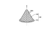
図3は、一実施形態における上流側トラップ部材を内側筒状部材の上流側開口側から見た外観斜視図である。図4は、一実施形態における上流側トラップ部材を下流側トラップ部材側から見た外観斜視図である。 FIG. 3 is an external perspective view of the upstream trap member in the embodiment as viewed from the upstream opening side of the inner cylindrical member. FIG. 4 is an external perspective view of the upstream trap member in the embodiment as viewed from the downstream trap member side.
図2〜図4に示すように、上流側トラップ部材140は、環状の基部141と、環状の基部141に接合された凹部142とを有する。環状の基部141は、内側筒状部材120の内側面に溶接等により取り付けられる。
As shown in FIGS. 2 to 4, the upstream
凹部142は、下流側トラップ部材130に近づく向きに凹んでいる。言い換えると、凹部142は、内側筒状部材120の上流側開口120aから下流側トラップ部材130に向けて流入される気体流の流れ方向に沿って凹んでいる。凹部142には、気体流を通過させる複数の貫通孔142aが形成される。貫通孔142aの密度及び径は、上流側トラップ部材140が上流側開口120aから流入される気体流を透過させるとともに、気体流に含まれる反応生成物を捕捉する機能を発揮するように、設定される。
The
また、上流側トラップ部材140は、凹部142の径Rが下流側トラップ部材130に近づく向きに沿って小さくなる形状に形成される。ここで、凹部142の径Rとは、下流側トラップ部材130に近づく向きに延びる軸線Xが仮想的に設定された場合に、軸線Xに直交する仮想平面Pに投射される凹部142の断面の縁部のうち互いに対向する縁部どうしの幅を指す。一実施形態では、上流側トラップ部材140は、図2〜図4に示すように、下流側トラップ部材130に近づく向き、すなわち、軸線Xの延在する方向に尖る円錐形状に形成される。
Further, the
次に、排気管72に設けられたトラップ装置100による作用の一例について説明する。処理チャンバー1内のプラズマ反応によって生じた反応生成物は、排気装置73によって処理チャンバー1内が減圧されることによって、気体流と共に排気管72を通流する。
Next, an example of the action of the
続いて、トラップ装置100よりも処理チャンバー1の排気口71側に位置する排気管72を通流する気体流は、上流側端壁111の上流側継ぎ手111b及び開口111aを介して、内側筒状部材120の上流側開口120aへ導入される。上流側トラップ部材140は、上流側開口120aから流入される気体流を透過させるとともに、気体流に含まれる反応生成物を捕捉する。詳細には、上流側トラップ部材140は、凹部142の複数の貫通孔142aによって気体流を透過させるとともに、凹部142の複数の貫通孔142a以外の部分によって気体流中の反応生成物を捕捉する。ここで、凹部142は、下流側トラップ部材130に近づく向きに凹んでいる。これにより、上流側トラップ部材140から気体流に作用する、下流側トラップ部材130に近づく向きとは逆向きの力が抑制されるので、上流側トラップ部材140から上流側開口120aへ向けた気体流の逆流が回避される。
Subsequently, the gas flow flowing through the
続いて、上流側トラップ部材140を透過した気体流は、下流側トラップ部材130へ到達する。下流側トラップ部材130は、上流側トラップ部材140を透過した気体流を透過させるとともに、気体流に含まれる、上流側トラップ部材140により捕捉されなかった反応生成物を捕捉する。
Subsequently, the gas flow that has passed through the
続いて、上流側トラップ部材140及び下流側トラップ部材130を透過した気体流は、内側筒状部材120の下流側開口120bを経て、トラップ装置100よりも排気装置73側に位置する排気管72へ流出する。
Subsequently, the gas flow that has permeated through the
以上、一実施形態のトラップ装置によれば、内側筒状部材120の内部に下流側トラップ部材130を配置するとともに、下流側トラップ部材130と、内側筒状部材120の上流側開口120aとの間に、下流側トラップ部材130に近づく向きに凹む凹部142を有する上流側トラップ部材140を配置した。このため、一実施形態のトラップ装置によれば、二重のトラップ部材を用いて気体流に含まれる反応生成物を捕捉しつつ、上流側トラップ部材140から気体流に作用する、下流側トラップ部材130に近づく向きとは逆向きの力を抑制することができる。その結果、一実施形態のトラップ装置によれば、気体流に含まれる反応生成物を効率良く除去することができる。
As described above, according to the trap device of one embodiment, the
また、一実施形態のトラップ装置では、上流側トラップ部材140は、凹部142の径Rが下流側トラップ部材130に近づく向きに沿って小さくなる形状に形成される。このため、一実施形態のトラップ装置によれば、凹部142による反応生成物の捕捉能力を向上することができる。その結果、一実施形態のトラップ装置によれば、気体流に含まれる反応生成物をさらに効率良く除去することができる。
Further, in the trap device of one embodiment, the
また、一実施形態のトラップ装置では、上流側トラップ部材140は、下流側トラップ部材130に近づく向きに尖る円錐形状に形成される。ここで、上流側トラップ部材140がパンチングメタル等の金属により成形される場合、円錐形状は金属から容易に成形可能な形状の一つである。このため、一実施形態のトラップ装置によれば、上流側トラップ部材140の成形性を向上させつつ、凹部142による反応生成物の捕捉能力を向上することができる。その結果、一実施形態のトラップ装置によれば、装置の製造に伴う負担を削減しつつ、気体流に含まれる反応生成物を効率良く除去することができる。
Further, in the trap device of one embodiment, the
(変形例1)
上記一実施形態では、下流側トラップ部材130と、内側筒状部材120の上流側開口120aとの間に一つの上流側トラップ部材140を配置するトラップ装置100を一例として示したが、これには限られない。以下、トラップ装置の変形例1について説明する。図5は、一実施形態におけるトラップ装置の変形例1の断面図である。
(Modification 1)
In the above embodiment, the
図5に示すように、変形例1に係るトラップ装置100では、上流側トラップ部材140は、下流側トラップ部材130に近づく向きに沿って、下流側トラップ部材130と、内側筒状部材120の上流側開口120aとの間に複数配置される。本変形例1では、3個の上流側トラップ部材140が、下流側トラップ部材130に近づく向き、すなわち、軸線Xの延在する方向に沿って、配置される。図5では、3個の上流側トラップ部材140は、軸線Xの延在する方向に沿って内側筒状部材120の上流側開口120a側から、上流側トラップ部材140−1、上流側トラップ部材140−2及び上流側トラップ部材140−3で示されている。上流側トラップ部材140−1、上流側トラップ部材140−2及び上流側トラップ部材140−3の各々の凹部142には、気体流を通過させる複数の貫通孔142aが形成される。本変形例1では、貫通孔142aの密度及び径は、上流側トラップ部材140−1、上流側トラップ部材140−2及び上流側トラップ部材140−3の間で同一である。
As shown in FIG. 5, in the
以上、変形例1のトラップ装置によれば、内側筒状部材120の内部に下流側トラップ部材130を配置するとともに、下流側トラップ部材130に近づく向きに沿って、下流側トラップ部材130と、内側筒状部材120の上流側開口120aとの間に上流側トラップ部材140を複数配置した。このため、変形例1のトラップ装置によれば、四重のトラップ部材を用いて気体流に含まれる反応生成物を捕捉しつつ、上流側トラップ部材140から気体流に作用する、下流側トラップ部材130に近づく向きとは逆向きの力を抑制することができる。その結果、変形例1のトラップ装置によれば、気体流に含まれる反応生成物をさらに効率良く除去することができる。
As described above, according to the trap device of
なお、上記変形例1では、貫通孔142aの密度及び径は、上流側トラップ部材140−1、上流側トラップ部材140−2及び上流側トラップ部材140−3の間で同一である例を示したが、これには限られない。例えば、貫通孔142aの密度及び径の少なくともいずれか一方が、上流側トラップ部材140−1、上流側トラップ部材140−2及び上流側トラップ部材140−3の間で異なることとしても良い。このようにすることによって、複数の上流側トラップ部材を透過する気体流の透過量や、複数の上流側トラップ部材によって捕捉される気体流中の反応生成物の捕捉量を微調整することが可能となる。
In the first modification, the density and diameter of the through
(変形例2)
また、上記一実施形態では、下流側トラップ部材130は、内側筒状部材120において、下流側端壁113から上流側端壁111に向けて離間しない位置に配置される例を示した、これには限られない。以下、トラップ装置の変形例2について説明する。図6は、一実施形態におけるトラップ装置の変形例2の断面図である。
(Modification 2)
Moreover, in the said one Embodiment, the
図6に示すように、変形例2に係るトラップ装置100では、下流側トラップ部材130は、内側筒状部材120の内部において、下流側端壁113から上流側端壁111に向けて所定の距離だけ離間した位置に配置される。ここで、所定の距離は、好ましくは、25mm〜100mmである。
As shown in FIG. 6, in the
以上、変形例2のトラップ装置によれば、下流側トラップ部材130は、内側筒状部材120の内部において、下流側端壁113から上流側端壁111に向けて所定の距離だけ離間した位置に配置される。このため、変形例2のトラップ装置によれば、内側筒状部材120の内部における圧力損失を低減しつつ、気体流に含まれる反応生成物を効率良く除去することができる。
As described above, according to the trap device of the second modification, the
1 処理チャンバー(処理容器)
2 下部電極
2a 基材
5 フォーカスリング
6 静電チャック
6a 電極
6b 絶縁層
16 上部電極
72 排気管(排気流路)
73 排気装置
100 トラップ装置
110 外側筒状部材(第1の筒状部材)
120 内側筒状部材(第2の筒状部材)
120a 上流側開口
120b 下流側開口
130 下流側トラップ部材
140 上流側トラップ部材
142 凹部
142a 貫通孔
1 Processing chamber (processing container)
2
73
120 inner cylindrical member (second cylindrical member)
120a Upstream opening 120b
Claims (7)
前記空間に着脱自在に配置され、気体流を流入させる上流側開口と、前記上流側開口から流入される前記気体流を流出させる下流側開口とを有する第2の筒状部材と、
前記下流側開口を塞ぐように前記第2の筒状部材の内部に配置された下流側トラップ部材と、
前記下流側トラップ部材と、前記第2の筒状部材の前記上流側開口との間に配置され、前記下流側トラップ部材に近づく向きに凹む凹部を有する上流側トラップ部材と
を備え、
前記第1の筒状部材は、
前記第2の筒状部材の前記下流側開口に対応する位置において前記第2の筒状部材の底部を収容する収容凹部を有することを特徴とするトラップ装置。 A first tubular member having a space;
A second cylindrical member that is detachably disposed in the space and has an upstream opening that allows a gas flow to flow in and a downstream opening that allows the gas flow flowing from the upstream opening to flow out;
A downstream trap member disposed inside the second tubular member so as to close the downstream opening;
An upstream trap member that is disposed between the downstream trap member and the upstream opening of the second tubular member and has a recess that is recessed toward the downstream trap member ;
The first cylindrical member is
A trap device having an accommodation recess for accommodating the bottom of the second cylindrical member at a position corresponding to the downstream opening of the second cylindrical member .
前記貫通孔の密度及び径の少なくともいずれか一方が複数の前記上流側トラップ部材の間で異なることを特徴とする請求項4に記載のトラップ装置。 Each of the plurality of upstream trap members includes a through-hole through which a gas flow passes,
The trap device according to claim 4, wherein at least one of the density and the diameter of the through holes is different among the plurality of upstream trap members.
前記第2の筒状部材の側方を囲繞する筒体と、
前記筒体の、前記第2の筒状部材の前記上流側開口側の端部を塞ぐように前記筒体に着脱自在に装着される上流側端壁と、
前記筒体の、前記第2の筒状部材の前記下流側開口側の端部を塞ぐように前記筒体に取り付けられ、前記筒体及び前記上流側端壁とともに前記空間を構築する下流側端壁と
を有し、
前記下流側トラップ部材は、前記第2の筒状部材の内部において、前記下流側端壁から前記上流側端壁に向けて所定の距離だけ離間した位置に配置されることを特徴とする請求項1〜5のいずれか一つに記載のトラップ装置。 The first cylindrical member is
A cylinder surrounding a side of the second cylindrical member;
An upstream end wall that is detachably attached to the cylindrical body so as to close an end of the cylindrical body on the upstream opening side of the second cylindrical member;
A downstream end of the cylindrical body that is attached to the cylindrical body so as to close an end of the second cylindrical member on the downstream opening side, and constructs the space together with the cylindrical body and the upstream end wall. A wall and
The downstream trap member is disposed in a position spaced apart from the downstream end wall by a predetermined distance from the downstream end wall in the second cylindrical member. The trap apparatus as described in any one of 1-5.
前記処理容器の内部を減圧するための排気装置と、
前記処理容器と前記排気装置とを接続する排気流路と、
前記排気流路に設けられたトラップ装置とを備えた基板処理装置であって、
前記トラップ装置は、
空間を有する第1の筒状部材と、
前記空間に着脱自在に配置され、気体流を流入させる上流側開口と、前記上流側開口から流入される前記気体流を流出させる下流側開口とを有する第2の筒状部材と、
前記下流側開口を塞ぐように前記第2の筒状部材の内部に配置された下流側トラップ部材と、
前記下流側トラップ部材と、前記第2の筒状部材の前記上流側開口との間に配置され、前記下流側トラップ部材に近づく向きに凹む凹部を有する上流側トラップ部材と
を備え、
前記第1の筒状部材は、
前記第2の筒状部材の前記下流側開口に対応する位置において前記第2の筒状部材の底部を収容する収容凹部を有することを特徴とする基板処理装置。 A processing container for processing a substrate to be processed;
An exhaust device for decompressing the inside of the processing vessel;
An exhaust flow path connecting the processing vessel and the exhaust device;
A substrate processing apparatus comprising a trap device provided in the exhaust flow path,
The trap device is:
A first tubular member having a space;
A second cylindrical member that is detachably disposed in the space and has an upstream opening that allows a gas flow to flow in and a downstream opening that allows the gas flow flowing from the upstream opening to flow out;
A downstream trap member disposed inside the second tubular member so as to close the downstream opening;
An upstream trap member that is disposed between the downstream trap member and the upstream opening of the second tubular member and has a recess that is recessed toward the downstream trap member ;
The first cylindrical member is
A substrate processing apparatus , comprising: a housing recess that houses a bottom of the second tubular member at a position corresponding to the downstream opening of the second tubular member .
Priority Applications (4)
| Application Number | Priority Date | Filing Date | Title |
|---|---|---|---|
| JP2013218718A JP6289859B2 (en) | 2013-10-21 | 2013-10-21 | Trap apparatus and substrate processing apparatus |
| TW103135921A TWI659123B (en) | 2013-10-21 | 2014-10-17 | Supplementary device and substrate processing device |
| US14/518,079 US20150107771A1 (en) | 2013-10-21 | 2014-10-20 | Trap apparatus and substrate processing apparatus |
| KR1020140142632A KR102301024B1 (en) | 2013-10-21 | 2014-10-21 | Trap apparatus and substrate processing apparatus |
Applications Claiming Priority (1)
| Application Number | Priority Date | Filing Date | Title |
|---|---|---|---|
| JP2013218718A JP6289859B2 (en) | 2013-10-21 | 2013-10-21 | Trap apparatus and substrate processing apparatus |
Publications (3)
| Publication Number | Publication Date |
|---|---|
| JP2015080738A JP2015080738A (en) | 2015-04-27 |
| JP2015080738A5 JP2015080738A5 (en) | 2016-11-04 |
| JP6289859B2 true JP6289859B2 (en) | 2018-03-07 |
Family
ID=52825133
Family Applications (1)
| Application Number | Title | Priority Date | Filing Date |
|---|---|---|---|
| JP2013218718A Active JP6289859B2 (en) | 2013-10-21 | 2013-10-21 | Trap apparatus and substrate processing apparatus |
Country Status (4)
| Country | Link |
|---|---|
| US (1) | US20150107771A1 (en) |
| JP (1) | JP6289859B2 (en) |
| KR (1) | KR102301024B1 (en) |
| TW (1) | TWI659123B (en) |
Families Citing this family (12)
| Publication number | Priority date | Publication date | Assignee | Title |
|---|---|---|---|---|
| CN106191812B (en) * | 2015-05-05 | 2019-01-22 | 中微半导体设备(上海)有限公司 | Chemical vapor deposition unit and the method for cleaning its exhaust outlet |
| DE102015219925A1 (en) * | 2015-10-14 | 2017-04-20 | Wacker Chemie Ag | Reactor for the deposition of polycrystalline silicon |
| JP6628653B2 (en) * | 2016-03-17 | 2020-01-15 | 東京エレクトロン株式会社 | Trap apparatus, exhaust system using the same, and substrate processing apparatus |
| CN109097755A (en) * | 2017-06-20 | 2018-12-28 | 华邦电子股份有限公司 | Processing chamber gas detecting system and its operating method |
| KR101957054B1 (en) * | 2017-10-31 | 2019-03-11 | 안호상 | LN2 Trap apparatus for sublimation purifier |
| KR101957055B1 (en) * | 2017-10-31 | 2019-03-11 | 안호상 | Sublimation purifier |
| KR102036273B1 (en) * | 2017-12-27 | 2019-10-24 | 주식회사 미래보 | Semiconductor process by-product collecting device |
| KR102209205B1 (en) * | 2019-08-21 | 2021-02-01 | 주식회사 미래보 | Flow path switching type collecting apparatus of by-product for semiconductor manufacturing process |
| US11583793B2 (en) | 2019-10-08 | 2023-02-21 | Utica Leaseco, Llc | Gas trap system having a conical inlet condensation region |
| JP2021186785A (en) | 2020-06-03 | 2021-12-13 | 東京エレクトロン株式会社 | Trap device and substrate processing device |
| CN113990730B (en) * | 2020-07-27 | 2023-10-31 | 中微半导体设备(上海)股份有限公司 | Plasma processing apparatus, gas flow regulating cover and gas flow regulating method thereof |
| US20220170151A1 (en) * | 2020-12-01 | 2022-06-02 | Applied Materials, Inc. | Actively cooled foreline trap to reduce throttle valve drift |
Family Cites Families (15)
| Publication number | Priority date | Publication date | Assignee | Title |
|---|---|---|---|---|
| JPS4944331B1 (en) | 1971-05-31 | 1974-11-27 | ||
| US4487618A (en) * | 1982-08-19 | 1984-12-11 | La-Man Corporation | Airline vapor trap |
| JP2544655Y2 (en) * | 1990-11-30 | 1997-08-20 | アマノ株式会社 | Mist collector |
| JPH0775713A (en) * | 1993-09-07 | 1995-03-20 | Teijin Ltd | Droplet removing device |
| US5593479A (en) * | 1995-02-02 | 1997-01-14 | Hmi Industries, Inc. | Filter system |
| US5669949A (en) * | 1995-04-21 | 1997-09-23 | Donaldson Company, Inc. | Air filtration arrangement |
| US5820641A (en) * | 1996-02-09 | 1998-10-13 | Mks Instruments, Inc. | Fluid cooled trap |
| US6093228A (en) * | 1998-11-18 | 2000-07-25 | Winbond Electronics Corp. | Method and device for collecting by-products individually |
| US6238514B1 (en) * | 1999-02-18 | 2001-05-29 | Mks Instruments, Inc. | Apparatus and method for removing condensable aluminum vapor from aluminum etch effluent |
| US6197119B1 (en) * | 1999-02-18 | 2001-03-06 | Mks Instruments, Inc. | Method and apparatus for controlling polymerized teos build-up in vacuum pump lines |
| JP2000256856A (en) * | 1999-03-11 | 2000-09-19 | Tokyo Electron Ltd | Treating device, vacuum exhaust system for treating device, vacuum cvd device, vacuum exhaust system for vacuum cvd device and trapping device |
| US7857883B2 (en) * | 2007-10-17 | 2010-12-28 | Cummins Filtration Ip, Inc. | Inertial gas-liquid separator with constrictable and expansible nozzle valve sidewall |
| US7871587B2 (en) * | 2008-12-23 | 2011-01-18 | Mks Instruments, Inc. | Reactive chemical containment system |
| KR101024504B1 (en) * | 2009-04-01 | 2011-03-31 | 주식회사 미래보 | Aapparatus for collecting remaining chemicals and by-products in semiconductor processing using particle inertia |
| KR101362439B1 (en) * | 2012-03-30 | 2014-02-13 | (주)아인스 | Trap for semiconductor fabrication |
-
2013
- 2013-10-21 JP JP2013218718A patent/JP6289859B2/en active Active
-
2014
- 2014-10-17 TW TW103135921A patent/TWI659123B/en active
- 2014-10-20 US US14/518,079 patent/US20150107771A1/en not_active Abandoned
- 2014-10-21 KR KR1020140142632A patent/KR102301024B1/en active IP Right Grant
Also Published As
| Publication number | Publication date |
|---|---|
| KR102301024B1 (en) | 2021-09-09 |
| TW201527581A (en) | 2015-07-16 |
| US20150107771A1 (en) | 2015-04-23 |
| TWI659123B (en) | 2019-05-11 |
| JP2015080738A (en) | 2015-04-27 |
| KR20150045906A (en) | 2015-04-29 |
Similar Documents
| Publication | Publication Date | Title |
|---|---|---|
| JP6289859B2 (en) | Trap apparatus and substrate processing apparatus | |
| KR102374799B1 (en) | Electrostatic chucking method and substrate processing apparatus | |
| JP5444044B2 (en) | Plasma processing apparatus and shower head | |
| JP5248370B2 (en) | Shower head and plasma processing apparatus | |
| JP6298391B2 (en) | Plasma processing method and plasma processing apparatus | |
| JP2010238961A (en) | Gas flow path structure and substrate processing apparatus | |
| JP5982206B2 (en) | Lower electrode and plasma processing apparatus | |
| JP6339866B2 (en) | Plasma processing apparatus and cleaning method | |
| JP2019176030A (en) | Plasma processing apparatus | |
| US20160042925A1 (en) | Baffle and substrate treating apparatus including the same | |
| JP2019220555A (en) | Mounting table and substrate processing apparatus | |
| JP2009200184A (en) | Plasma processing apparatus, and baffle plate of plasma processing apparatus | |
| JP6878174B2 (en) | Plasma etching method and plasma etching equipment | |
| JP6219179B2 (en) | Plasma processing equipment | |
| TW201703098A (en) | Surface processing method for upper electrode, plasma processing device, and upper electrode | |
| KR20200051505A (en) | Placing table and substrate processing apparatus | |
| JP5302813B2 (en) | Deposit control cover and plasma processing apparatus | |
| JP7357513B2 (en) | plasma processing equipment | |
| JP2021044385A (en) | Heat medium circulation system and substrate processing device | |
| KR102661835B1 (en) | Plasma etching method and plasma etching apparatus | |
| JP2021012960A (en) | Plasma processing apparatus | |
| US20210384017A1 (en) | Trap apparatus and substrate processing apparatus | |
| KR102583259B1 (en) | Apparatus for treating substrate and method for processing a substrate | |
| KR102299884B1 (en) | Apparatus for treating substrate and plasma treating method | |
| JP2021097065A (en) | Ring assembly, board support, and board processing device |
Legal Events
| Date | Code | Title | Description |
|---|---|---|---|
| A521 | Request for written amendment filed |
Free format text: JAPANESE INTERMEDIATE CODE: A523 Effective date: 20160913 |
|
| A621 | Written request for application examination |
Free format text: JAPANESE INTERMEDIATE CODE: A621 Effective date: 20160913 |
|
| A977 | Report on retrieval |
Free format text: JAPANESE INTERMEDIATE CODE: A971007 Effective date: 20171017 |
|
| A131 | Notification of reasons for refusal |
Free format text: JAPANESE INTERMEDIATE CODE: A131 Effective date: 20171031 |
|
| A521 | Request for written amendment filed |
Free format text: JAPANESE INTERMEDIATE CODE: A523 Effective date: 20171215 |
|
| TRDD | Decision of grant or rejection written | ||
| A01 | Written decision to grant a patent or to grant a registration (utility model) |
Free format text: JAPANESE INTERMEDIATE CODE: A01 Effective date: 20180123 |
|
| A61 | First payment of annual fees (during grant procedure) |
Free format text: JAPANESE INTERMEDIATE CODE: A61 Effective date: 20180207 |
|
| R150 | Certificate of patent or registration of utility model |
Ref document number: 6289859 Country of ref document: JP Free format text: JAPANESE INTERMEDIATE CODE: R150 |
|
| R250 | Receipt of annual fees |
Free format text: JAPANESE INTERMEDIATE CODE: R250 |
|
| R250 | Receipt of annual fees |
Free format text: JAPANESE INTERMEDIATE CODE: R250 |
|
| R250 | Receipt of annual fees |
Free format text: JAPANESE INTERMEDIATE CODE: R250 |