JP6288992B2 - Illumination device and imaging device - Google Patents

Illumination device and imaging device Download PDF

Info

Publication number
JP6288992B2
JP6288992B2 JP2013179271A JP2013179271A JP6288992B2 JP 6288992 B2 JP6288992 B2 JP 6288992B2 JP 2013179271 A JP2013179271 A JP 2013179271A JP 2013179271 A JP2013179271 A JP 2013179271A JP 6288992 B2 JP6288992 B2 JP 6288992B2
Authority
JP
Japan
Prior art keywords
angle
unit
movable part
movable
bounce
Prior art date
Legal status (The legal status is an assumption and is not a legal conclusion. Google has not performed a legal analysis and makes no representation as to the accuracy of the status listed.)
Active
Application number
JP2013179271A
Other languages
Japanese (ja)
Other versions
JP2015049280A (en
JP2015049280A5 (en
Inventor
健一郎 山下
健一郎 山下
Current Assignee (The listed assignees may be inaccurate. Google has not performed a legal analysis and makes no representation or warranty as to the accuracy of the list.)
Canon Inc
Original Assignee
Canon Inc
Priority date (The priority date is an assumption and is not a legal conclusion. Google has not performed a legal analysis and makes no representation as to the accuracy of the date listed.)
Filing date
Publication date
Application filed by Canon Inc filed Critical Canon Inc
Priority to JP2013179271A priority Critical patent/JP6288992B2/en
Priority to US14/470,799 priority patent/US9395600B2/en
Priority to CN201410437084.5A priority patent/CN104423122B/en
Publication of JP2015049280A publication Critical patent/JP2015049280A/en
Priority to US15/187,420 priority patent/US10042235B2/en
Publication of JP2015049280A5 publication Critical patent/JP2015049280A5/ja
Application granted granted Critical
Publication of JP6288992B2 publication Critical patent/JP6288992B2/en
Active legal-status Critical Current
Anticipated expiration legal-status Critical

Links

Images

Classifications

    • GPHYSICS
    • G03PHOTOGRAPHY; CINEMATOGRAPHY; ANALOGOUS TECHNIQUES USING WAVES OTHER THAN OPTICAL WAVES; ELECTROGRAPHY; HOLOGRAPHY
    • G03BAPPARATUS OR ARRANGEMENTS FOR TAKING PHOTOGRAPHS OR FOR PROJECTING OR VIEWING THEM; APPARATUS OR ARRANGEMENTS EMPLOYING ANALOGOUS TECHNIQUES USING WAVES OTHER THAN OPTICAL WAVES; ACCESSORIES THEREFOR
    • G03B15/00Special procedures for taking photographs; Apparatus therefor
    • G03B15/02Illuminating scene
    • G03B15/03Combinations of cameras with lighting apparatus; Flash units
    • G03B15/05Combinations of cameras with electronic flash apparatus; Electronic flash units
    • FMECHANICAL ENGINEERING; LIGHTING; HEATING; WEAPONS; BLASTING
    • F21LIGHTING
    • F21VFUNCTIONAL FEATURES OR DETAILS OF LIGHTING DEVICES OR SYSTEMS THEREOF; STRUCTURAL COMBINATIONS OF LIGHTING DEVICES WITH OTHER ARTICLES, NOT OTHERWISE PROVIDED FOR
    • F21V14/00Controlling the distribution of the light emitted by adjustment of elements
    • F21V14/02Controlling the distribution of the light emitted by adjustment of elements by movement of light sources
    • FMECHANICAL ENGINEERING; LIGHTING; HEATING; WEAPONS; BLASTING
    • F21LIGHTING
    • F21VFUNCTIONAL FEATURES OR DETAILS OF LIGHTING DEVICES OR SYSTEMS THEREOF; STRUCTURAL COMBINATIONS OF LIGHTING DEVICES WITH OTHER ARTICLES, NOT OTHERWISE PROVIDED FOR
    • F21V5/00Refractors for light sources
    • F21V5/04Refractors for light sources of lens shape
    • F21V5/045Refractors for light sources of lens shape the lens having discontinuous faces, e.g. Fresnel lenses
    • FMECHANICAL ENGINEERING; LIGHTING; HEATING; WEAPONS; BLASTING
    • F21LIGHTING
    • F21VFUNCTIONAL FEATURES OR DETAILS OF LIGHTING DEVICES OR SYSTEMS THEREOF; STRUCTURAL COMBINATIONS OF LIGHTING DEVICES WITH OTHER ARTICLES, NOT OTHERWISE PROVIDED FOR
    • F21V7/00Reflectors for light sources
    • GPHYSICS
    • G03PHOTOGRAPHY; CINEMATOGRAPHY; ANALOGOUS TECHNIQUES USING WAVES OTHER THAN OPTICAL WAVES; ELECTROGRAPHY; HOLOGRAPHY
    • G03BAPPARATUS OR ARRANGEMENTS FOR TAKING PHOTOGRAPHS OR FOR PROJECTING OR VIEWING THEM; APPARATUS OR ARRANGEMENTS EMPLOYING ANALOGOUS TECHNIQUES USING WAVES OTHER THAN OPTICAL WAVES; ACCESSORIES THEREFOR
    • G03B2215/00Special procedures for taking photographs; Apparatus therefor
    • G03B2215/05Combinations of cameras with electronic flash units
    • G03B2215/0514Separate unit
    • G03B2215/0517Housing
    • G03B2215/0525Reflector
    • G03B2215/0528Reflector movable reflector, e.g. change of illumination angle or illumination direction

Landscapes

  • Engineering & Computer Science (AREA)
  • General Engineering & Computer Science (AREA)
  • Physics & Mathematics (AREA)
  • General Physics & Mathematics (AREA)
  • Stroboscope Apparatuses (AREA)
  • Studio Devices (AREA)
  • Circuit Arrangement For Electric Light Sources In General (AREA)
  • Lighting Device Outwards From Vehicle And Optical Signal (AREA)

Description

本発明は、照明装置の照射方向を変更するための駆動制御に関するものである。   The present invention relates to drive control for changing the irradiation direction of a lighting device.

従来、照明装置の光を天井等に向けて照射して天井等からの拡散反射光を被写体に照射する発光撮影(以下、バウンス発光撮影とする)が知られている。バウンス発光撮影によれば、照明装置の光を直接的ではなく間接的に被写体に照射することができるため、柔らかい光での描写が可能となる。   2. Description of the Related Art Conventionally, flash photography (hereinafter referred to as bounce flash photography) is known in which light from a lighting device is irradiated toward a ceiling or the like and a subject is irradiated with diffuse reflected light from the ceiling or the like. According to the bounce flash photography, the subject can be irradiated with light from the illumination device indirectly instead of directly, so that it is possible to depict with soft light.

特許文献1では、手動で発光部を回転させ、所定角度でクリック機構にて発光部を停止可能なストロボ装置が提案されている。特許文献1に記載のストロボ装置はクリック機構とともに所定の角度で発光部の回動禁止する係止機構を備えている。さらに、特許文献1に記載のストロボ装置の発光部は少なくともクリック機構を備えた左右方向回動可能な構造になっている。   Patent Document 1 proposes a strobe device capable of manually rotating a light emitting unit and stopping the light emitting unit with a click mechanism at a predetermined angle. The strobe device described in Patent Document 1 includes a locking mechanism that prohibits rotation of the light emitting unit at a predetermined angle together with a click mechanism. Furthermore, the light emitting unit of the strobe device described in Patent Document 1 has a structure that can be rotated in the left-right direction and includes at least a click mechanism.

また近年では、特許文献2および3に見られるように、ストロボ装置の発光方向をモーター等の駆動源を用いた駆動機構によって回動し自動的に照射方向を調整する所謂オートバウンス機能を備えたストロボ装置も提案されている。   In recent years, as seen in Patent Documents 2 and 3, the flash device has a so-called auto bounce function that automatically adjusts the irradiation direction by rotating the light emitting direction of the strobe device by a driving mechanism using a driving source such as a motor. Strobe devices have also been proposed.

特開2008−180913号公報JP 2008-180913 A 特開2011−170014号公報JP 2011-170014 A 特開2009−75340号公報JP 2009-75340 A

特許文献3に記載のストロボ装置は、ヘッド部筐体内部でリモート発光部が回動する構造であるのに対して、特許文献2に記載のストロボ装置は、特許文献1に記載のストロボ装置と同様に発光部を収める筐体(以降、ヘッド部)が回動する構造である。これらのオートバウンス機能を備えたストロボ装置では、ユーザーの使い勝手を考えると、オートバウンス機能以外にユーザーが直接ヘッド部を把持して手動でヘッド部を回動可能な構造が好ましい。   The strobe device described in Patent Document 3 has a structure in which the remote light emitting unit rotates inside the head unit housing, whereas the strobe device described in Patent Document 2 is the same as the strobe device described in Patent Document 1. Similarly, the casing (hereinafter referred to as the head unit) that houses the light emitting unit is rotated. In the stroboscope device having the auto bounce function, considering the convenience of the user, a structure in which the user can directly grip the head part and manually rotate the head part in addition to the auto bounce function is preferable.

通常、駆動機構中には手動でヘッド部を回動させる場合や駆動機構により回動するヘッド部が障害物に衝突するなどの異常が起きた場合などを考慮して、モーターを含む駆動機構の保護のために滑りクラッチなどのクラッチ機構を介在させる。そこで、特許文献1に記載のクリック機構や係止機構は駆動機構の動作の妨げになるので搭載しない方が好ましい。   Normally, in the drive mechanism, the drive mechanism including the motor is taken into consideration when the head part is manually rotated or when an abnormality such as the head part rotated by the drive mechanism collides with an obstacle occurs. A clutch mechanism such as a slip clutch is interposed for protection. Therefore, it is preferable not to mount the click mechanism and the locking mechanism described in Patent Document 1 because they hinder the operation of the drive mechanism.

しかしながら、所定角度で停止したヘッド部の保持が前述のクラッチ機構の保持力のみによって行われることになると、ヘッド部に外力が加わったときにヘッド部の角度変化が生じ易くなる。そのため、ヘッド部がユーザーの意図しない角度になってしまった場合は被写体に適切に照明光があたらずに失敗写真となってしまう。   However, if the head portion stopped at a predetermined angle is held only by the holding force of the clutch mechanism described above, the angle of the head portion is likely to change when an external force is applied to the head portion. For this reason, when the head portion is at an angle not intended by the user, the subject is not properly illuminated with illumination light, resulting in a failed photo.

そうした問題を解消するためには、ヘッド部の保持力を確保するためにクラッチ機構の保持力を極端に高くするか、駆動機構の動作の妨げとなるようなクリック機構や係止機構を追加する必要が生じてしまう。この場合、ヘッド部の駆動機構はクラッチ機構の保持力やクリック機構の抗力に見合うだけ強度を持たなければならず、さらにクリック機構の抗力に打ち勝つために高出力で大型のモーターも必要であるため、駆動機構が大型化しコストアップの要因にもなる。また、係止機構を追加する場合は駆動機構動作時に解除が必要となり、機構が複雑化してストロボ装置が大型化しコストアップの要因にもなる。   In order to solve such a problem, the holding force of the clutch mechanism is made extremely high in order to secure the holding force of the head portion, or a click mechanism or a locking mechanism that hinders the operation of the drive mechanism is added. Necessity arises. In this case, the drive mechanism of the head must be strong enough to match the holding force of the clutch mechanism and the drag force of the click mechanism, and a large motor with a high output is required to overcome the drag force of the click mechanism. As a result, the drive mechanism becomes larger and the cost increases. In addition, when a locking mechanism is added, it is necessary to release it when the drive mechanism is operated. This complicates the mechanism, which increases the size of the strobe device and increases costs.

そこで、本発明は、ユーザーにとって好適な照射方向となるように制御できるようにすることを目的とする。 Therefore, an object of the present invention is to enable control so that the irradiation direction is suitable for the user .

上記目的を達成するために、本発明に係る照明装置は、発光部と、前記発光部を備え、本体部に対して回動可能に保持される可動部と、前記可動部を駆動させる駆動手段と、前記駆動手段を用いずに前記可動部が回動された場合に、前記駆動手段を用いて前記可動部を回動前の位置に復帰させる制御手段と、前記可動部の複数の箇所に設けられた接触検知手段と、を有し、前記制御手段は、前記駆動手段を用いずに前記可動部が回動された場合に、前記接触検知手段により前記可動部の複数の箇所に対する接触を検知しなければ前記駆動手段を用いて前記可動部を回動前の位置に復帰させ、前記接触検知手段により前記可動部の複数の箇所に対する接触を検知していれば前記駆動手段を用いて前記可動部を回動前の位置に復帰させないことを特徴とする。 In order to achieve the above object, an illumination device according to the present invention includes a light emitting unit, a movable unit that includes the light emitting unit and is rotatably held with respect to a main body unit, and a driving unit that drives the movable unit. And when the movable part is rotated without using the drive means, the control means for returning the movable part to the position before the rotation using the drive means, and a plurality of locations of the movable part. Contact control means provided, and when the movable part is rotated without using the drive means, the control means makes contact with a plurality of parts of the movable part by the contact detection means. If not detected, the drive means is used to return the movable part to the position before rotation, and if the contact detection means detects contact with a plurality of locations of the movable part, the drive means is used to Do not return the movable part to the position before turning. And butterflies.

本発明によれば、ユーザーにとって好適な照射方向となるように制御できる。 According to the present invention, it is possible to control the irradiation direction suitable for the user .

本発明の実施形態に係るストロボ装置の三面図である。It is a three-view figure of the strobe device which concerns on embodiment of this invention. 本発明の実施形態に係るストロボ装置の断面図である。1 is a cross-sectional view of a strobe device according to an embodiment of the present invention. 本発明の実施形態に係るストロボ装置の制御にかかわるブロック図である。It is a block diagram regarding control of the strobe device which concerns on embodiment of this invention. 本発明の実施形態に係るヘッド部駆動機構の斜視図である。It is a perspective view of a head part drive mechanism concerning an embodiment of the present invention. 本発明の実施形態に係るヘッド部駆動機構の平面図である。It is a top view of the head part drive mechanism concerning the embodiment of the present invention. 本発明の実施形態に係るヘッド部駆動機構のクラッチ機構を示した断面図である。It is sectional drawing which showed the clutch mechanism of the head part drive mechanism which concerns on embodiment of this invention. バウンス角度検知手段に用いる基板のパターンを示した平面図である。It is the top view which showed the pattern of the board | substrate used for a bounce angle detection means. バウンス角度検知手段の信号変移表を示した図である。It is the figure which showed the signal transition table of a bounce angle detection means. 本発明の実施形態に係るストロボ装置のLCD表示を示した図である。It is the figure which showed LCD display of the strobe device which concerns on embodiment of this invention. 第1の実施形態にかかる手動バウンス判別処理のフローチャートを示した図である。It is the figure which showed the flowchart of the manual bounce discrimination | determination process concerning 1st Embodiment. 第1の実施形態にかかる手動バウンス処理のフローチャートを示した図である。It is the figure which showed the flowchart of the manual bounce process concerning 1st Embodiment. 第2の実施形態にかかる手動バウンス判別処理のフローチャートを示した図である。It is the figure which showed the flowchart of the manual bounce discrimination | determination process concerning 2nd Embodiment. 第3の実施形態にかかる手動バウンス処理のフローチャートを示した図である。It is the figure which showed the flowchart of the manual bounce process concerning 3rd Embodiment. 左右駆動モーター21の制御方法を示した図である。FIG. 5 is a diagram illustrating a method for controlling the left / right drive motor 21.

以下に、本発明の好ましい実施の形態を添付の図面に基づいて詳細に説明する。   Hereinafter, preferred embodiments of the present invention will be described in detail with reference to the accompanying drawings.

(第1の実施形態)
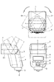
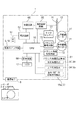
図1は、本実施形態に係る照明装置であるストロボ装置1の三面図である。図2は、ストロボ装置1の断面図であり、図2(a)はストロボ装置全体の中央断面を示す図、図2(b)はバウンス部3を図2(a)の断面A−Aで切断した局部断面を示す図である。図3はストロボ装置1の制御にかかわる内部構成を示すブロック図である。
(First embodiment)
FIG. 1 is a three-view diagram of a strobe device 1 that is an illumination device according to the present embodiment. 2 is a cross-sectional view of the strobe device 1. FIG. 2A is a diagram showing a central cross section of the entire strobe device. FIG. 2B is a cross-sectional view taken along the line AA in FIG. It is a figure which shows the cut | disconnected local cross section. FIG. 3 is a block diagram showing an internal configuration relating to control of the strobe device 1.

ストロボ装置1はヘッド部2、バウンス部3、制御部4の三つの筐体に分かれており、ヘッド部2はバウンス部3に対して軸x周りに、バウンス部3はヘッド部2を抱えた状態で制御部4に対し軸y周りに回動可能となっている。以降は図1において、x軸周りのヘッド部2の回動方向を上下方向、y軸周りのヘッド部2の回動方向を左右方向と称し、左右方向はストロボ装置1の上方から見て矢印R方向を右方向、矢印L方向を左方向と定義する。ヘッド部2は、図1にて実線で示した正面方向に光を照射する正位置(上下方向0°、左右方向0°)状態に対して、二点鎖線で示すように上方向に最大120°まで、左右方向にそれぞれ最大180°回動可能である。すなわち、本体部である制御部4に対して、ヘッド部2及びバウンス部3からなる可動部が上下方向(第1の方向)及び左右方向(第2の方向)にそれぞれ所定の回動角度まで回動可能に保持される。また以降は、可動部の本体部に対する上下方向及び左右方向の回動動作をバウンス動作とする。また以降は、可動部の本体部に対する上下方向及び左右方向の回動角度をバウンス角度とする。ちなみに、正位置におけるバウンス角度は上下方向、左右方向ともに0°である。   The strobe device 1 is divided into three housings: a head unit 2, a bounce unit 3, and a control unit 4. The head unit 2 has an axis x around the bounce unit 3, and the bounce unit 3 has the head unit 2. In the state, it can be rotated around the axis y with respect to the control unit 4. Hereinafter, in FIG. 1, the rotation direction of the head portion 2 around the x axis is referred to as the up-down direction, and the rotation direction of the head portion 2 around the y-axis is referred to as the left-right direction. The R direction is defined as the right direction, and the arrow L direction is defined as the left direction. The head unit 2 has a maximum of 120 in the upward direction as indicated by a two-dot chain line with respect to the normal position (vertical direction 0 °, horizontal direction 0 °) where light is emitted in the front direction indicated by the solid line in FIG. Up to 180 ° can be rotated up to 180 ° in the left-right direction. That is, with respect to the control unit 4 which is the main body unit, the movable unit composed of the head unit 2 and the bounce unit 3 moves to a predetermined rotation angle in the vertical direction (first direction) and the horizontal direction (second direction), respectively. It is held rotatably. Further, hereinafter, the pivoting operation in the up and down direction and the left and right direction with respect to the main body of the movable unit is referred to as a bounce operation. Further, hereinafter, the rotation angles in the vertical direction and the horizontal direction with respect to the main body portion of the movable portion are referred to as bounce angles. Incidentally, the bounce angle at the normal position is 0 ° in both the vertical and horizontal directions.

バウンス動作は後述のモーターを駆動源とする駆動機構による回動と、ユーザーがヘッド部2を直接把持して行う外力による回動が可能である。駆動機構による回動は、ストロボ装置1(もしくはストロボ装置1に接続されたカメラシステム)が発光撮影時に適切な照射方向(バウンス角度)を選択してヘッド部2を自動的に回動させる機能、いわゆるオートバウンス機能に利用される。   The bounce operation can be rotated by a driving mechanism using a motor, which will be described later, as well as rotating by an external force performed by the user directly holding the head unit 2. The rotation by the drive mechanism is a function in which the strobe device 1 (or a camera system connected to the strobe device 1) automatically rotates the head unit 2 by selecting an appropriate irradiation direction (bounce angle) during flash photography. It is used for the so-called auto bounce function.

ヘッド部2の筐体内には、キセノン管12、反射傘11、フレネルレンズ19、で構成される発光光学部が内蔵されている。発光光学部は多くの場合キセノン管12および反射傘11がフレネルレンズ19に対して光軸方向に相対移動して照射範囲を変更する所謂ズーム機構を備える。なお、ズーム機構については公知の構造を用いればよく、詳細な説明は省略する。   In the housing of the head unit 2, a light emitting optical unit including a xenon tube 12, a reflector 11 and a Fresnel lens 19 is built. In many cases, the light emitting optical unit includes a so-called zoom mechanism in which the xenon tube 12 and the reflector 11 are moved relative to the Fresnel lens 19 in the optical axis direction to change the irradiation range. Note that a known structure may be used for the zoom mechanism, and detailed description thereof is omitted.

ヘッド部2の両側面にはタッチセンサー51が配置される。タッチセンサー51はユーザーがヘッド部2を把持して手動でバウンス角度を設定する際にユーザーの手が接触したことを検知するものである。なお本実施形態では、接触検知を行う構成としてタッチセンサー51を用いる例を説明するが、ユーザーによる把持を有効に検知できるものであれば機械的なスイッチであっても構わない。また、タッチセンサーのよる検出方式は特に限定されず、抵抗膜方式や静電容量方式など公知の方式を用いればよい。また、ヘッド部2の形状によってはユーザーに把持される際にユーザーに接触しやすい箇所は異なるため、ヘッド部2の両側面で接触検知しなくてもよい。ユーザーに把持される際には少なくとも互いに独立した複数の箇所でユーザーと接触すると考えられるので、ユーザーと接触しやすい複数の箇所で接触検知できる構成であればよい。   Touch sensors 51 are disposed on both side surfaces of the head unit 2. The touch sensor 51 detects that the user's hand has touched when the user grips the head unit 2 and manually sets the bounce angle. In the present embodiment, an example in which the touch sensor 51 is used as a configuration for performing contact detection will be described. However, a mechanical switch may be used as long as gripping by a user can be detected effectively. The detection method using the touch sensor is not particularly limited, and a known method such as a resistance film method or a capacitance method may be used. Further, depending on the shape of the head unit 2, the portion that is easily touched by the user when gripped by the user is different, and therefore, contact detection may not be performed on both side surfaces of the head unit 2. When grasped by the user, it is considered that the user makes contact with the user at a plurality of locations that are independent from each other.

ヘッド部2は、x軸の回動軸上で内側から固定される上下駆動エンドギア39と軸受40によってバウンス部3に上下方向に回動可能に軸支される。バウンス部3の筐体内にはキセノン管12を発光させるための高電圧の電荷を蓄積するメインコンデンサ13が収納される。他には、後述する上下駆動モーター27を駆動源とする上下方向回動用の上下方向駆動機構63と左右駆動モーター21を駆動源とする左右方向回動用の左右方向駆動機構62の大半が収納されている。   The head portion 2 is pivotally supported by the bounce portion 3 so as to be pivotable in the vertical direction by a vertical drive end gear 39 and a bearing 40 that are fixed from the inside on the pivot axis of the x axis. In the housing of the bounce unit 3, a main capacitor 13 that stores high-voltage charges for causing the xenon tube 12 to emit light is housed. In addition, most of a vertical driving mechanism 63 for vertical rotation using a vertical driving motor 27 described later as a driving source and a horizontal driving mechanism 62 for horizontal rotation using a horizontal driving motor 21 as a driving source are housed. ing.

バウンス部3は、制御部4上部に内側から固定される左右駆動エンドギア26に形成された軸受穴26bに軸部3aが軸支され、軸部3a下面に固定される回転係止板36によって抜け止めされ、制御部4に左右方向に回動可能に軸支される。   The bounce part 3 is supported by a shaft hole 3b formed in a bearing hole 26b formed in the left and right drive end gear 26 fixed to the upper part of the control part 4 from the inside, and is removed by a rotation locking plate 36 fixed to the lower surface of the shaft part 3a. It is stopped and is pivotally supported by the control unit 4 so as to be rotatable in the left-right direction.

制御部4の筐体内にはストロボ装置1の動作を司るCPU16が実装されたメイン基板15が収納される。CPU16には外部表示用の表示部であるLCD17を動作させる表示回路68や、後述するバウンス角度検出手段61、バウンス駆動回路73等が接続される。またバウンス角度記憶手段72はバウンス角度検知手段61によって得られたヘッド部2の角度情報を随時記憶するものであり、CPU内蔵もしく外部のEPROM等の記憶装置を使用する。制御部4の背面には外部表示用のLCD17を視認するためのLCD窓7、ストロボ装置1の各種設定を行うための操作釦8やダイアル10等の操作スイッチ類が配置される。制御部4下面の脚部5にはカメラとの通信を行うための複数の接続端子6が配置される。14はストロボ装置1に装填された複数個の電池であり、その下側には電源回路67、充電回路66の一部等が実装されたサブ基板18が配置される。図3のブロック図における発光制御回路65は、通常前述のサブ基板18や発光部内の不図示の基板等に分散して配置される。   A main board 15 on which a CPU 16 that controls the operation of the strobe device 1 is mounted is housed in the housing of the control unit 4. Connected to the CPU 16 are a display circuit 68 for operating the LCD 17 which is a display unit for external display, a bounce angle detection means 61, a bounce drive circuit 73 and the like which will be described later. The bounce angle storage means 72 stores the angle information of the head unit 2 obtained by the bounce angle detection means 61 as needed, and uses a storage device such as an internal EPROM or an external EPROM. On the back surface of the control unit 4, an operation window such as an LCD window 7 for visually recognizing the LCD 17 for external display, an operation button 8 for making various settings of the strobe device 1, and a dial 10 are arranged. A plurality of connection terminals 6 for communicating with the camera are disposed on the leg 5 on the lower surface of the control unit 4. Reference numeral 14 denotes a plurality of batteries loaded in the strobe device 1, and a sub-board 18 on which a power supply circuit 67, a part of the charging circuit 66, and the like are mounted is disposed below the batteries. The light emission control circuits 65 in the block diagram of FIG. 3 are usually distributed and arranged on the above-described sub-substrate 18 and a substrate (not shown) in the light-emitting portion.

前述した操作釦8の一つはオートバウンス機能を備えたストロボ装置1のオートバウンス機能の有無を切り替える役割が割り当てられている。   One of the operation buttons 8 described above is assigned the role of switching the presence or absence of the auto bounce function of the strobe device 1 having the auto bounce function.

図9はLCD17の表示状態を示しており、該当する操作釦8を押下するごとに図9(a)に示すオートバウンスモードと図9(b)に示す手動バウンスモードに表示が切り替わる。図9(a)のようにLCD17の右下に「AUTO」という指標51が表示されるとストロボ装置1のオートバウンス機能が有効な状態であることがわかる。オートバウンスモードとは文字通り、ストロボ装置(もしくはストロボ装置が装着されたカメラシステム)が発光撮影時に適切な照射方向を選択して、左右方向駆動機構62、上下方向駆動機構63によりヘッド部2を自動的に回動させるモードである。オートバウンスモード時の照射方向の選択方法は特に限定されず、取得した被写体までの距離と反射体までの距離とに基づいて照射方向を選択する方法や照射方向を変えて複数回発光を行って得られた複数の測光結果に基づいて選択する方法などを用いればよい。   FIG. 9 shows the display state of the LCD 17, and each time the corresponding operation button 8 is pressed, the display is switched between the auto bounce mode shown in FIG. 9 (a) and the manual bounce mode shown in FIG. 9 (b). As shown in FIG. 9A, when the index 51 “AUTO” is displayed on the lower right of the LCD 17, it is understood that the auto bounce function of the strobe device 1 is in an effective state. The auto bounce mode literally means that the strobe device (or the camera system equipped with the strobe device) selects an appropriate irradiation direction during flash photography, and the head unit 2 is automatically moved by the left / right direction driving mechanism 62 and the up / down direction driving mechanism 63. It is a mode to rotate it automatically. The method of selecting the irradiation direction in the auto bounce mode is not particularly limited, and a method of selecting the irradiation direction based on the acquired distance to the subject and the distance to the reflector, or performing multiple light emission by changing the irradiation direction A method of selecting based on a plurality of obtained photometric results may be used.

図9(a)に対して、図9(b)のようにLCD17の右下に「M」という指標52が表示されるとストロボ装置1のオートバウンス機能は無効となり、手動バウンスモードであることがわかる。手動バウンスモードとはユーザーが任意に照射方向を設定できるモードであり、言い換えるとオートバウンス機能を用いない従来のストロボ装置と同様な状態である。当然ながら手動バウンスモードでは、ヘッド部2の回動はヘッド部2を把持して回動させるなどユーザーによる直接の操作が必要となる。   In contrast to FIG. 9A, when the index 52 “M” is displayed in the lower right of the LCD 17 as shown in FIG. 9B, the auto bounce function of the strobe device 1 is disabled and the manual bounce mode is set. I understand. The manual bounce mode is a mode in which the user can arbitrarily set the irradiation direction. In other words, the manual bounce mode is the same state as a conventional strobe device that does not use the auto bounce function. As a matter of course, in the manual bounce mode, the rotation of the head unit 2 requires a direct operation by the user such as gripping and rotating the head unit 2.

なお、LCD17の表示に示される55〜58の指標は、バウンス角度記憶手段72に記憶されている現在のバウンス角度を示すためのものである。55は上下方向を示すアイコン、56は上下方向の回動角度、57は左右方向を示すアイコン、58は左右方向の回動角度である。また他の操作釦8やダイアル10等を用いた所定の操作より、表示上の回動角度を変更することで左右方向駆動機構62、上下方向駆動機構63を用いた回動も可能である。   The indicators 55 to 58 shown on the display of the LCD 17 are for indicating the current bounce angle stored in the bounce angle storage means 72. 55 is an icon indicating the vertical direction, 56 is a rotation angle in the vertical direction, 57 is an icon indicating the horizontal direction, and 58 is a rotation angle in the horizontal direction. Further, by using a predetermined operation using the other operation buttons 8, dial 10, or the like, it is possible to rotate using the left and right direction driving mechanism 62 and the vertical direction driving mechanism 63 by changing the rotation angle on the display.

次に左右方向駆動機構62、上下方向駆動機構63の構成について説明する。図4はバウンス部3筐体内から制御部4上部にわたって配置される左右方向駆動機構62、上下方向駆動機構63を示した斜視図である。図5は左右方向駆動機構62、上下方向駆動機構63の平面図であり、図5(a)はヘッド部2が正位置(0°)にある状態の左右方向駆動機構62、上下方向駆動機構63を示し、右側に制御部下方から見た図を、左側に側方から見た図を示している。さらに図5(b)はヘッド部2が右方向へ60°回動した状態の左右方向駆動機構62、上下方向駆動機構63を制御部下方から見た図を示している。さらに図5(c)はヘッド部2が右方向へ180°回動した状態の左右方向駆動機構62、上下方向駆動機構63を制御部下方から見た図である。   Next, the structure of the left-right direction drive mechanism 62 and the up-down direction drive mechanism 63 is demonstrated. FIG. 4 is a perspective view showing the left-right direction driving mechanism 62 and the up-down direction driving mechanism 63 arranged from the inside of the bounce unit 3 housing to the upper part of the control unit 4. 5 is a plan view of the left-right direction driving mechanism 62 and the up-down direction driving mechanism 63. FIG. 5A is a left-right direction driving mechanism 62 and a vertical direction driving mechanism in a state where the head portion 2 is in the normal position (0 °). 63 is shown on the right side as viewed from below the control unit, and on the left side as viewed from the side. Further, FIG. 5B shows a view of the left and right direction driving mechanism 62 and the up and down direction driving mechanism 63 in a state in which the head portion 2 is rotated by 60 ° rightward as viewed from below the control unit. Further, FIG. 5C is a view of the left and right direction drive mechanism 62 and the up and down direction drive mechanism 63 in a state where the head unit 2 is rotated 180 ° rightward as viewed from below the control unit.

左右方向駆動機構62、上下方向駆動機構63の駆動源に用いる左右駆動モーター21及び上下駆動モーター27はDCモーターであり、一般的なモータードライバを備えたバウンス駆動回路73によって制御される。左右駆動モーター21と上下駆動モーター27には後述するクラッチ機構64を備えた初段ギア22、28が取り付けられている。29、30、31は上下駆動モーター27の初段ギア28の駆動力を前述の上下駆動エンドギア39に適切な減速比で伝達するための伝達ギアである。伝達ギア29、30、31によって伝達された駆動力により上下駆動エンドギア39が回転することで直結しているヘッド部2が上下方向に回動する。また上下駆動エンドギア39にはバウンス部3内部へ向かう面側に接点ブラシ34が取り付けられており、バウンス部3筐体内に保持されている上下角度検知基板35と接触し相対回転することでバウンス角度検出手段61として上下方向の角度検出を行う。   The left / right drive motor 21 and the up / down drive motor 27 used as drive sources for the left / right direction drive mechanism 62 and the up / down direction drive mechanism 63 are DC motors, and are controlled by a bounce drive circuit 73 having a general motor driver. First-stage gears 22 and 28 having a clutch mechanism 64 described later are attached to the left and right drive motor 21 and the vertical drive motor 27. Reference numerals 29, 30 and 31 denote transmission gears for transmitting the driving force of the first gear 28 of the vertical drive motor 27 to the above-described vertical drive end gear 39 at an appropriate reduction ratio. When the vertical drive end gear 39 is rotated by the driving force transmitted by the transmission gears 29, 30, 31, the head unit 2 that is directly connected rotates in the vertical direction. Further, a contact brush 34 is attached to the vertical drive end gear 39 on the surface side toward the inside of the bounce unit 3. The bounce angle is obtained by contacting and rotating relative to the vertical angle detection substrate 35 held in the casing of the bounce unit 3. The detection means 61 performs angle detection in the vertical direction.

一方、23、24、25は左右駆動モーター21の初段ギア22の駆動力を前述の左右駆動エンドギア26内周に形成された内歯歯車26aへ適切な減速比で伝達するための伝達ギアである。伝達ギア23、24間はカサ歯歯車が用いられ伝達ギアの回転軸方向を90°変位させている。水平駆動エンドギア26は制御部4側に固定されているので、モーター21が回転して伝達ギア25より駆動力を受けると、バウンス部3(すなわちヘッド部2)側が制御部4に対して左右方向に回動することになる。バウンス部3下面に固定された回転係止板36には接点ブラシ37が取り付けられており、左右エンドギア26下面に取り付けられた左右角度検知基板38と接触し相対回動することで、バウンス角度検出手段61として左右方向の角度検出を行う。   On the other hand, 23, 24 and 25 are transmission gears for transmitting the driving force of the first gear 22 of the left and right drive motor 21 to the internal gear 26a formed on the inner periphery of the left and right drive end gear 26 at an appropriate reduction ratio. . A bevel gear is used between the transmission gears 23 and 24, and the rotational axis direction of the transmission gear is displaced by 90 °. Since the horizontal drive end gear 26 is fixed to the control unit 4 side, when the motor 21 rotates and receives a driving force from the transmission gear 25, the bounce unit 3 (that is, the head unit 2) side is laterally moved with respect to the control unit 4. Will be rotated. A contact brush 37 is attached to the rotation locking plate 36 fixed to the lower surface of the bounce unit 3. The bounce angle detection is performed by contacting and rotating relative to the left / right angle detection board 38 attached to the lower surface of the left / right end gear 26. As means 61, angle detection in the left-right direction is performed.

メイン基板15の上方に配置された左右回転ストッパー32は、制御部4内に所定量だけ左右方向に搖動可能に保持されており、不図示のバネ機構等により通常は図5(a)、(b)に示すように中央に停止した状態となっている。ヘッド部2を左右方向に回動させると180°回動直前で回転係止板36の外周に形成された係止突起36aが左右回転ストッパー32のリブ32aに当接し左右回転ストッパー32を揺動させる。図5(c)で示すようにヘッド部を右方向に180°回転させると左右回転ストッパー32は図中左側へ移動し、移動量を規制されている左右回転ストッパー32の停止によりヘッド部2は180°回動の状態で回動を抑制される。左右回転ストッパー32に固定された接点ブラシ33はメイン基板上のパターン15aと接触し相対移動することで、バウンス角度検出手段61として180°回転時の回転方向検出を行う。   The left / right rotation stopper 32 disposed above the main board 15 is held in the control unit 4 so as to be slidable in the left / right direction by a predetermined amount. Usually, a spring mechanism (not shown) or the like is used in FIG. As shown in b), it is stopped at the center. When the head part 2 is rotated in the left-right direction, the locking protrusion 36a formed on the outer periphery of the rotation locking plate 36 immediately before the 180 ° rotation comes into contact with the rib 32a of the left-right rotation stopper 32 and swings the left-right rotation stopper 32. Let As shown in FIG. 5C, when the head portion is rotated 180 ° in the right direction, the left / right rotation stopper 32 moves to the left side in the drawing, and the head portion 2 is moved by the stop of the left / right rotation stopper 32 whose movement amount is regulated. The rotation is suppressed in the state of 180 ° rotation. The contact brush 33 fixed to the left and right rotation stopper 32 is in contact with the pattern 15a on the main substrate and relatively moves, so that the bounce angle detection means 61 detects the rotation direction during 180 ° rotation.

ここで前述のクラッチ機構64の詳細について説明する。図6は前述の左右駆動モーター21、上下駆動モーター27に取り付けられた初段ギア22、28のクラッチ機構64を示した断面図である。なお、初段ギア22と28とでクラッチ機構64は同じ構成であるため、以下では初段ギア22についてのみ説明し初段ギア28については説明を省略する。クラッチ機構64は、左右駆動モーター21の回転軸21aの軸に固着されたプーリー45とプーリー45に軸支され自由回動可能な初段ギア22、フリクションバネ46、フリクションワッシャ48および初段ギア22を抜け止めするワッシャ47で構成される。プーリー45の回転力はフリクションバネ46の付勢力によって与えられた摩擦力により初段ギア22に伝達される。左右方向駆動機構62、上下方向駆動機構63にクラッチ機構64が設けられている理由は、ヘッド部2をユーザーが手動で回動させた場合やヘッド部2を自動回動させた際に障害物に当たった場合に、モーターやギア列に過大な負荷をかけないためである。なお、ストロボ装置1の電源が投入されている状態では左右駆動モーター21、上下駆動モーター27はバウンス駆動回路73によって入力端子を短絡したいわゆるブレーキ状態に制御されており、外力によりヘッド部2が容易に回らないようになっている。クラッチ機構64の結合力は左右駆動モーター21、上下駆動モーター27がブレーキ状態にある場合に外力でヘッド部2が回動した際に滑りを生ずるように設定されている。このとき、ヘッド部2の自重で回転するほど軽すぎず、かつユーザーがヘッド部2を直接把持して回動させる上で重すぎない適切な値に結合力は設定されている。なお、本実施形態では、モーター軸に取り付けられる初段ギア22、28に一般的な滑りクラッチ機構であるクラッチ機構64を設けたが、クラッチ機構は伝達ギア列中の他の箇所に設けてもよい。また、滑りクラッチ機構に限定するものではなくラッチのかみ合いによるクラッチ機構等でもよい。   Here, the details of the clutch mechanism 64 will be described. FIG. 6 is a cross-sectional view showing the clutch mechanism 64 of the first gears 22 and 28 attached to the left and right drive motors 21 and 27. Since the clutch mechanism 64 has the same configuration in the first gears 22 and 28, only the first gear 22 will be described below, and the description of the first gear 28 will be omitted. The clutch mechanism 64 passes through a pulley 45 fixed to the shaft of the rotation shaft 21 a of the left and right drive motor 21, the first gear 22 that is pivotally supported by the pulley 45, the friction spring 46, the friction washer 48, and the first gear 22. It is composed of a washer 47 for stopping. The rotational force of the pulley 45 is transmitted to the first gear 22 by the frictional force given by the biasing force of the friction spring 46. The reason why the clutch mechanism 64 is provided in the left and right direction driving mechanism 62 and the vertical direction driving mechanism 63 is that an obstacle is present when the user manually rotates the head unit 2 or when the head unit 2 is automatically rotated. This is because an excessive load is not applied to the motor and the gear train when hit. In the state where the power of the strobe device 1 is turned on, the left and right drive motors 21 and the vertical drive motor 27 are controlled to a so-called brake state in which the input terminals are short-circuited by the bounce drive circuit 73, and the head unit 2 can be easily operated by an external force. It is designed not to turn around. The coupling force of the clutch mechanism 64 is set so as to cause a slip when the head portion 2 is rotated by an external force when the left and right drive motor 21 and the vertical drive motor 27 are in a brake state. At this time, the coupling force is set to an appropriate value that is not too light to rotate by the weight of the head unit 2 and that is not too heavy for the user to grip and rotate the head unit 2 directly. In the present embodiment, the first stage gears 22 and 28 attached to the motor shaft are provided with the clutch mechanism 64 which is a general slip clutch mechanism, but the clutch mechanism may be provided at other locations in the transmission gear train. . Further, the present invention is not limited to the sliding clutch mechanism, and a clutch mechanism or the like by latch engagement may be used.

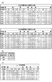
次に図7および図8を用いてバウンス角度検出手段61の詳細を説明する。図7はバウンス角度検知に用いる各基板のパターンを示した平面図であり、図7(a)は左右角度検知基板38のパターン、図7(b)はメイン基板15上のパターン15a、図7(c)は上下角度検知基板35のパターンを示している。図8はバウンス角度検知におけるヘッド部2のバウンス角度に対する信号の切り替わりを示した信号変移表を示す図である。図8(a)は左右角度検知基板38による左右角度検出を、図8(b)はメイン基板上のパターン15aによる左右180°回転時の回転方向検出を、図8(c)は上下角度検知基板35による上下角度検出を示している。   Next, details of the bounce angle detection means 61 will be described with reference to FIGS. 7 is a plan view showing the pattern of each substrate used for bounce angle detection. FIG. 7A is a pattern of the left / right angle detection substrate 38, FIG. 7B is a pattern 15a on the main substrate 15, and FIG. (C) shows the pattern of the vertical angle detection substrate 35. FIG. 8 is a diagram showing a signal transition table showing signal switching with respect to the bounce angle of the head unit 2 in the bounce angle detection. 8A shows left / right angle detection by the left / right angle detection board 38, FIG. 8B shows rotation direction detection when the pattern 15a on the main board rotates 180 ° left and right, and FIG. 8C shows up / down angle detection. The vertical angle detection by the substrate 35 is shown.

まずヘッド部2が左右方向に回動した場合について説明する。左右角度検知基板38には円周方向に沿って3列にCPU15と接続されるbit1からbit7までの信号のパターンが配置される。bit1〜bit5のパターンは外側の2列に全周360°にわたってそれぞれ分割された状態で配置され、中央列の半周以上の領域には接地(GND)パターンが配置される。また最内周の列にはbit6およびbit7のパターンがそれぞれ略半周の範囲で対向するように配置される。   First, the case where the head unit 2 is rotated in the left-right direction will be described. On the left / right angle detection board 38, signal patterns from bit 1 to bit 7 connected to the CPU 15 are arranged in three rows along the circumferential direction. The patterns of bit1 to bit5 are arranged in the outer two rows in a state of being divided over the entire circumference of 360 °, and a ground (GND) pattern is arranged in a region of a half or more of the central row. In the innermost circumferential row, the patterns of bit 6 and bit 7 are arranged so as to face each other within a range of approximately a half circumference.

黒点で示すBh1およびBh2は回転係止板36に固定される接点ブラシ37の接触点でありヘッド部2が正位置にある状態を示している。接点ブラシ37の4か所の接触点Bh1は左右角度検知基板38の外周2列のパターンに対して接触可能で、回転軸に対称にとなるように配置される。接触点Bh2は接点ブラシ37の一方の側のみに配置され、左右角度検知基板38最内周のパターン列に接触可能である。なお図中においてヘッド部2が右方向に回動すると接触点Bh1、Bh2は左回転し、ヘッド部2が左方向に回動すると接触点Bh1、Bh2は右回転する。   Bh1 and Bh2 indicated by black dots are contact points of the contact brush 37 fixed to the rotation locking plate 36 and indicate a state in which the head portion 2 is in the normal position. The four contact points Bh1 of the contact brush 37 are capable of contacting with the two rows of the outer periphery of the left / right angle detection substrate 38 and are arranged so as to be symmetric with respect to the rotation axis. The contact point Bh2 is disposed only on one side of the contact brush 37, and can contact the pattern row on the innermost periphery of the left / right angle detection substrate 38. In the figure, the contact points Bh1, Bh2 rotate to the left when the head unit 2 rotates to the right, and the contact points Bh1, Bh2 rotate to the right when the head unit 2 rotates to the left.

各bit1〜bit7の信号は電気的にプルアップされた状態でCPU16に接続されており、接点ブラシ37と接触しない状態では高電位(1)である。接点ブラシ37が接触すると、接点ブラシ37が常にGNDパターンに接触しているのでGNDレベル(0)に切り替わる。左右角度検知基板38の外側2列のパターンに対しては、GNDパターンとの接触点を除く3か所の接触点でbit1からbit5の信号のうち最大3つの信号を同時にGNDレベル(0)にすることができる。   The signals of bit 1 to bit 7 are connected to the CPU 16 in an electrically pulled up state, and are at a high potential (1) when not in contact with the contact brush 37. When the contact brush 37 comes into contact, the contact brush 37 is always in contact with the GND pattern, so the level is switched to the GND level (0). For the two rows of patterns on the outside of the left / right angle detection board 38, a maximum of three signals from bit1 to bit5 are simultaneously set to the GND level (0) at three contact points excluding the contact point with the GND pattern. can do.

図8(a)の信号変移表に示すように左右方向角度検出は15°きざみの回動角度とその中間角度にあることを検出可能であり、角度が変位するに従って各bitの信号が1つずつ変化するいわゆるグレーコードを出力するように構成されている。bit1からbit5までの信号は接点ブラシ37の接触点Bh1を回転軸に対して対称に配置しているために360°回転する範囲内で180°ごとに同じ信号の組み合わせが検出される。そこで最内周の列に配置されるbit6とbit7によりバウンス部3が左右どちらに回転したか判定する。バウンス部3が左回転するとbit6が0になり、右回転するとbit7が0になる。   As shown in the signal transition table of FIG. 8 (a), it is possible to detect that the angle in the left-right direction is at a rotation angle of 15 ° and an intermediate angle thereof, and one bit signal is provided as the angle is displaced. It is configured to output a so-called gray code that changes gradually. As for the signals from bit1 to bit5, since the contact point Bh1 of the contact brush 37 is arranged symmetrically with respect to the rotation axis, the same signal combination is detected every 180 ° within the range of 360 ° rotation. Therefore, it is determined whether the bounce unit 3 has rotated to the left or right by bits 6 and 7 arranged in the innermost row. When the bounce unit 3 rotates to the left, bit 6 becomes 0, and when it rotates to the right, bit 7 becomes 0.

ところで上記までの場合0°と180°の信号の組み合わせが同じであり0°と180°の区別ができない。さらには180°の状態にある場合において左右どちらの方向に回転して180°に至ったかが区別ができない。そこで前述の左右回転ストッパー32の搖動に連動する接点ブラシ33とメイン基板上のパターン15aの接触の切り替わりを利用する。例えば、前述の説明のようにヘッド部2が右回転して180°の位置になると、図7の(b)上で通常は黒点Btで示す位置にある接点ブラシ33の接触点が、左右回転ストッパー32と共に左方へ移動する。そして、bit1のパターンとGNDパターンが接続されbit1の信号がGNDレベル(0)となることで、右回転における180°の位置と判定する。逆にバウンス部を左回転させて180°位置にすると左右回転ストッパーは右側に搖動するのでメイン基板上のbit2がGNDレベル(0)となり、左回転における180°の位置と判定する。   By the way, in the above case, the combination of 0 ° and 180 ° signals is the same, and 0 ° and 180 ° cannot be distinguished. Furthermore, in the case of 180 °, it is impossible to distinguish between the left and right directions to 180 °. Therefore, the switching of contact between the contact brush 33 and the pattern 15a on the main board, which is interlocked with the swing of the left and right rotation stopper 32, is used. For example, as described above, when the head unit 2 rotates clockwise to a position of 180 °, the contact point of the contact brush 33 that is normally at the position indicated by the black point Bt in FIG. It moves to the left together with the stopper 32. Then, when the bit1 pattern and the GND pattern are connected and the signal of bit1 becomes the GND level (0), it is determined that the position is 180 ° in the clockwise rotation. Conversely, when the bounce unit is rotated counterclockwise to the 180 ° position, the left / right rotation stopper swings to the right side, so that bit 2 on the main board becomes the GND level (0), and is determined to be the 180 ° position in the left rotation.

次にヘッド部2が上下方向に回動した場合について説明する。   Next, the case where the head part 2 is rotated in the vertical direction will be described.

図7の(c)の平面図と図8の(c)の信号変位表に示すように、上下角度検知基板35のパターンはヘッド部2の角度変化に伴い左右検知基板38とほぼ同等の信号を送出するように配置される。15°きざみの回動角度とその中間角度にある事を検出し、角度が変位するに従って各bitの信号が1つずつ変化するいわゆるグレーコードを出力する点も同じである。ただし上下方向は1方向120°までしか回動しないので、左右角度検知基板38に設けられていたbit6とbit7のパターンは使用せず、2列に配置されるbit1からbit5の信号のパターンを使用する。またbit6とbit7の信号が無いので正位置(0°)の状態のみbit1の信号が高電位(1)となるようにbit1のパターンの設置角度が異なっている。   As shown in the plan view of FIG. 7C and the signal displacement table of FIG. 8C, the pattern of the vertical angle detection board 35 is a signal substantially equivalent to the left and right detection board 38 as the angle of the head portion 2 changes. Is arranged to send out. The same is true in that a so-called gray code in which the signal of each bit changes one by one as the angle is displaced is detected by detecting that the rotation angle is in the range of 15 ° and an intermediate angle. However, since the vertical direction can only be rotated up to 120 ° in one direction, the pattern of bit 6 and bit 7 provided on the left and right angle detection board 38 is not used, and the signal pattern of bit 1 to bit 5 arranged in two rows is used. To do. Further, since there is no bit6 and bit7 signal, the bit1 pattern installation angle is different so that the bit1 signal is at a high potential (1) only in the normal position (0 °).

黒点で示すBvは上下駆動エンドギア39に固定される接点ブラシ34の接触点でありヘッド部2が正位置にある状態を示している。接点ブラシ34の4か所の接触点Bvは上下角度検知基板35の2列のパターンに対して接触可能で回転軸に対称に配置され、ヘッド部2が上方へ回動すると図7(c)中において接触点Bvは右回転する。   Bv indicated by a black dot is a contact point of the contact brush 34 fixed to the vertical drive end gear 39, and shows a state where the head portion 2 is in the normal position. The four contact points Bv of the contact brush 34 can contact the two rows of patterns of the vertical angle detection substrate 35 and are arranged symmetrically with respect to the rotation axis. When the head portion 2 rotates upward, FIG. Inside, the contact point Bv rotates to the right.

以上のように、左右方向駆動機構62、上下方向駆動機構63において所定角度で停止したヘッド部2の保持は前述のクラッチ機構64の結合力によってのみ行われるだけなので、不意な衝突等でヘッド部2の角度が変化する可能性がある。ヘッド部2がユーザーの意図しない角度になってしまった場合は被写体に適切に照明光があたらずに失敗写真となってしまう。   As described above, the head unit 2 stopped at a predetermined angle in the left and right direction driving mechanism 62 and the up and down direction driving mechanism 63 is only held by the coupling force of the clutch mechanism 64 described above. The angle of 2 may change. If the head unit 2 is at an angle not intended by the user, the subject is not properly illuminated with illumination light, resulting in a failed photo.

ヘッド部2の保持力を確保するためにはクラッチ機構64の結合力を極端に高くする必要が生ずるが、左右方向駆動機構62、上下方向駆動機構63はクラッチ機構64の結合力に見合うだけ強度を持たなければならない。そのため、左右方向駆動機構62、上下方向駆動機構63が大型化する恐れがある。ヘッド部2の角度変化を検知して自動的に元の角度に戻す手法も考えられるが、ユーザーが意図的に手動でヘッド部2を回動させた場合は元の角度に戻さないほうが好ましい。そこで、以下では、本実施形態における、ユーザーがヘッド部2を手動で回動させたのか、不慮の外力により角度変化が生じたのかを判別する方法について説明する。   In order to secure the holding force of the head portion 2, it is necessary to extremely increase the coupling force of the clutch mechanism 64, but the left and right direction driving mechanism 62 and the vertical direction driving mechanism 63 are strong enough to match the coupling force of the clutch mechanism 64. Must have. Therefore, there is a possibility that the left-right direction driving mechanism 62 and the up-down direction driving mechanism 63 are increased in size. A method of detecting the angle change of the head unit 2 and automatically returning it to the original angle is also conceivable. However, when the user intentionally manually rotates the head unit 2, it is preferable not to return to the original angle. Therefore, in the following, a method for determining whether the user has manually rotated the head unit 2 or whether an angle change has occurred due to an unexpected external force will be described.

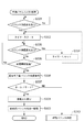
図10および図11は手動バウンス判別処理及び手動バウンス処理のフローチャートである。なお、以降で説明する手動バウンス判別処理では、ヘッド部2が上下方向、左右方向のいずれの方向に変化しても処理内容に大きな違いはないため、変化の方向が上下方向か左右方向かの区別はしていない。   10 and 11 are flowcharts of the manual bounce discrimination process and the manual bounce process. Note that in the manual bounce determination process described below, there is no significant difference in processing contents regardless of whether the head unit 2 changes in the vertical direction or the horizontal direction, so whether the direction of change is the vertical direction or the horizontal direction. No distinction is made.

図10におけるS101はヘッド部2の角度変化を検出するためのルーチンであり、バウンス角度検出手段61の信号の変化をCPU16が常時監視している。   S101 in FIG. 10 is a routine for detecting a change in the angle of the head unit 2, and the CPU 16 constantly monitors a change in the signal of the bounce angle detection means 61.

ヘッド部2が外力により回動されてバウンス角度検出手段61のいずれかの信号が切り替わると、CPU16は、S102に進みヘッド部2の両側面に配置されたタッチセンサー51によって接触検知がなされているか否かを判断する。タッチセンサー51にて接触を検知した場合はS103に進み、CPU16は、両側面双方のタッチセンサー51が接触を検知しているか否か判断する。これは通常ユーザーがヘッド部2を手動で回動させる際にはヘッド部2を両側面から挟み込むように把持するためであり、双方のタッチセンサー51に接触の検知があった場合はS104に進み手動バウンスである旨のフラグを立てS105に進む。それに対して、S103において1側面のみの検知であった場合はユーザーによる手動操作ではなく他の物体等が接触したものと判断しS105へ進む。   When the head part 2 is rotated by an external force and any of the signals of the bounce angle detection means 61 is switched, the CPU 16 proceeds to S102 and is touch detected by the touch sensors 51 arranged on both side surfaces of the head part 2? Judge whether or not. When contact is detected by the touch sensor 51, the process proceeds to S103, and the CPU 16 determines whether or not the touch sensors 51 on both side surfaces detect contact. This is because the user normally grips the head unit 2 so as to be sandwiched from both sides when the head unit 2 is manually rotated. If the touch sensor 51 detects contact, the process proceeds to S104. A flag indicating manual bounce is set and the process proceeds to S105. On the other hand, if only one side is detected in S103, it is determined that another object or the like is not in contact with the manual operation by the user, and the process proceeds to S105.

S105でCPU16はタイマーをスタートさせ次のS106にてバウンス角度の変化を待ち、引き続きヘッド部2の外力により回動されるか判定する。バウンス角度が変化した場合は、CPU16はS107に分岐してタイマーをリセットしてからS102に戻り、再びヘッド部2の両側面に配置されたタッチセンサー51によって接触検知がなされているか否かを判断する。S106にてバウンス角度の変化が無い場合は一定間隔でS108へ進み、CPU16はタイマーが所定の時間を経過しているか否かを判定する。所定時間経過していないならS106に戻り再びバウンス角度の変化を待つ。S108にてタイマーが所定時間経過した場合は、CPU16は、外力によるヘッド部2の回動が終了したものと判断し次のS109のステップへ進み、変化終了後のバウンス角度をバウンス角度検知手段61から取得する。   In S105, the CPU 16 starts a timer, waits for a change in the bounce angle in the next S106, and determines whether or not it is continuously rotated by the external force of the head unit 2. If the bounce angle has changed, the CPU 16 branches to S107, resets the timer, returns to S102, and again determines whether or not contact is detected by the touch sensors 51 arranged on both sides of the head unit 2. To do. If there is no change in the bounce angle in S106, the process proceeds to S108 at regular intervals, and the CPU 16 determines whether or not a predetermined time has elapsed. If the predetermined time has not elapsed, the process returns to S106 and waits for a change in the bounce angle again. When the predetermined time has elapsed in S108, the CPU 16 determines that the rotation of the head unit 2 due to the external force has been completed, and proceeds to the next step of S109 to determine the bounce angle after the change is completed as the bounce angle detection means 61. Get from.

次のS110では、CPU16は手動バウンスフラグが立てられているか否かを判別し、フラグが立てられていた場合はユーザーが任意にバウンス角度を設定したものと判断しS113の手動バウンス処理のフローへ移行する。手動バウンスフラグが立てられていない場合は、CPU16は不慮の外力によるヘッド部2の回動と判断し、S111に進む。S111ではCPU16は、バウンス角度記憶手段72に記憶されている角度変化以前のヘッド部2のバウンス角度とS110で取得した変化後のヘッド部2のバウンス角度の差分から外力によるヘッド部2の回動方向を算出する。そしてS112へ進み、CPU16は、算出された回動方向に応じてヘッド部2をバウンス角度記憶手段72に記憶されている角度変化検知以前(回動前)の角度に左右方向駆動機構62、上下方向駆動機構63を用いて強制的に復帰させる。なお、S111で算出された回動方向が左右方向及び上下方向の両方の場合、左右方向の回動と上下方向の回動を順に行っても同時行ってもよい。   In the next S110, the CPU 16 determines whether or not the manual bounce flag is set. If the flag is set, it is determined that the user has arbitrarily set the bounce angle, and the flow proceeds to the manual bounce processing flow in S113. Transition. If the manual bounce flag is not set, the CPU 16 determines that the head unit 2 is rotated by an unexpected external force, and proceeds to S111. In S111, the CPU 16 rotates the head unit 2 by an external force from the difference between the bounce angle of the head unit 2 before the change in angle stored in the bounce angle storage unit 72 and the bounce angle of the head unit 2 after the change acquired in S110. Calculate the direction. In step S112, the CPU 16 moves the head unit 2 to the angle before the angle change detection (before rotation) stored in the bounce angle storage unit 72 according to the calculated rotation direction. The direction drive mechanism 63 is used to forcibly return. In addition, when the rotation direction calculated by S111 is both the left-right direction and the up-down direction, the rotation in the left-right direction and the rotation in the up-down direction may be performed sequentially or simultaneously.

S110の判断でS113の手動バウンス処理に移行すると図11に示すように、S120でCPU16は、現在停止しているヘッド部2のバウンス角度が標準角度であるか否かを判断する。標準角度とは、図8の信号変位表で菱形のマークを付けている角度であり、クリック機構でヘッド部2を係止する従来のストロボ装置に準じた角度である。なお、図8に示した標準角度はあくまで例であり、正位置となる角度を含んでいれば図8に示した角度すべてを含む必要はないし、図8に示されていない角度を含んでいてもよい。ただし、すべての角度を標準角度とするのは無意味であるため、標準角度は左右駆動モーター21や上下駆動モーター27により駆動可能な角度の一部であって正位置となる角度を含む角度であればよい。   When the process proceeds to the manual bounce process of S113 in the determination of S110, as shown in FIG. 11, in S120, the CPU 16 determines whether or not the bounce angle of the currently stopped head unit 2 is a standard angle. The standard angle is an angle at which a rhombus mark is given in the signal displacement table of FIG. 8, and is an angle according to a conventional strobe device that locks the head unit 2 with a click mechanism. Note that the standard angle shown in FIG. 8 is merely an example, and it is not necessary to include all the angles shown in FIG. 8 as long as the angle that is the normal position is included, and includes an angle not shown in FIG. Also good. However, since it is meaningless to set all the angles as standard angles, the standard angles are a part of angles that can be driven by the left and right drive motors 21 and the vertical drive motors 27 and include angles that are normal positions. I just need it.

S120において標準角度で停止していると判断するとS124の処理に進み、標準角度で停止していないと判断するとS121に進む。S121でCPU16は、バウンス角度記憶手段72に記憶されている角度変化以前のヘッド部2のバウンス角度とS110で取得した変化後(回動後)のヘッド部2のバウンス角度の差分から外力によるヘッド部2の回動方向を算出する。S122でCPU16は、算出された回動方向へ左右方向駆動機構62、上下方向駆動機構63を用いてさらにヘッド部2を回動させる。S123でCPU16は、ヘッド部2のバウンス角度が最も近い標準角度に至るとヘッド部2の回動を停止させる。次の124でCPU16は、現在停止しているヘッド部2のバウンス角度をバウンス角度記憶手段72に上書きで記憶させ、S125にてCPU16はLCD17上に現在のバウンス角度を表示させる。   If it is determined in S120 that the vehicle is stopped at the standard angle, the process proceeds to S124. If it is determined that the vehicle is not stopped at the standard angle, the process proceeds to S121. In S121, the CPU 16 determines the head by an external force from the difference between the bounce angle of the head unit 2 before the angle change stored in the bounce angle storage unit 72 and the bounce angle of the head unit 2 after the change (after rotation) acquired in S110. The rotation direction of the unit 2 is calculated. In S122, the CPU 16 further rotates the head unit 2 using the left and right direction driving mechanism 62 and the vertical direction driving mechanism 63 in the calculated rotation direction. In S123, the CPU 16 stops the rotation of the head unit 2 when the bounce angle of the head unit 2 reaches the closest standard angle. In the next 124, the CPU 16 stores the bounce angle of the currently stopped head unit 2 in the bounce angle storage means 72 by overwriting, and in S 125 the CPU 16 displays the current bounce angle on the LCD 17.

上記のS120からS123におけるヘッド部2の回動制御は、ユーザーの操作をアシストするものとして働く。例えば、ヘッド部2が正位置状態にあった場合から上方もしくは左右方向に60°の位置までユーザーが手動でヘッド部2を回動させようとした場合には、60°より浅い角度まで旋回させれば自動的に標準角度である60°まで回動することになる。逆に、正位置以外にあるヘッド部2を正位置へ戻そうとした場合は、ヘッド部2の角度が60°以下になったところで手を離せば自動的に標準角度である正位置(0°)まで回動する。   The rotation control of the head unit 2 in the above S120 to S123 works to assist the user's operation. For example, when the user tries to manually turn the head unit 2 from the position where the head unit 2 is in the normal position to the position of 60 ° upward or left and right, the head unit 2 is turned to an angle shallower than 60 °. Then, it automatically rotates to 60 ° which is a standard angle. On the other hand, when the head portion 2 other than the normal position is to be returned to the normal position, if the hand portion is released when the angle of the head portion 2 becomes 60 ° or less, the normal position (0 ).

なお、図8に示した標準角度の中に0°と60°との間の角度を含まないのは、上下方向、左右方向のいずれにおいても60°より小さい(浅い)バウンス角度では直接光が被写体に照射されバウンス発光撮影の効果が低下する可能性があるためである。   The reason why the standard angle shown in FIG. 8 does not include an angle between 0 ° and 60 ° is that direct light is emitted at a bounce angle smaller than 60 ° (shallow) in both the vertical and horizontal directions. This is because there is a possibility that the effect of the bounce flash photography may be reduced by irradiating the subject.

ここで図14を用いて、ヘッド部2を左右方向に回動させる左右駆動モーター21の制御方法について説明する。   Here, a control method of the left and right drive motor 21 for rotating the head unit 2 in the left and right direction will be described with reference to FIG.

バウンス発光撮影においては、バウンス角度に数度程度の誤差が生じていても被写体への拡散反射光は大きく変化することはないが、ヘッド部2を正位置に停止する際はヘッド部2を回動させた位置に停止させる場合よりも厳密な精度で停止させる必要がある。これは、ヘッド部2が正位置にある場合に照明光を正しく被写体に照射するためである。通常、発光光学部に備えられたオートズーム機構によって照射光の照射範囲はカメラのレンズの焦点距離に応じた照射範囲に制御されるが、できるだけガイドナンバーを向上させるため周辺部の光量が許容できるぎりぎりの状態となるように設定されることが多い。そのため、ヘッド部2が正位置からズレた状態では周辺光量の落ちた部分が被写体によりかかるようになり、いわゆる配光ムラの現象が顕著になる。本実施形態のストロボ装置1においては、上下方向は正位置である0°の位置で下方へ向かわないように機械的な突き当たりで停止させることは可能であるが、左右方向については正位置である0°の位置で機械的な突き当たりを設けることができない。以上の理由により、左右方向において、正位置である0°の位置に停止させる際にはより精度のよいモーター制御が必要となる。   In bounce flash photography, even if an error of about several degrees occurs in the bounce angle, the diffuse reflected light to the subject does not change greatly, but when the head unit 2 is stopped at the normal position, the head unit 2 is turned. It is necessary to stop with a stricter accuracy than when stopping at the moved position. This is to irradiate the subject with illumination light correctly when the head unit 2 is in the normal position. Usually, the irradiation range of the irradiation light is controlled to the irradiation range according to the focal length of the lens of the camera by the auto zoom mechanism provided in the light emitting optical unit, but the light quantity in the peripheral part can be allowed to improve the guide number as much as possible. In many cases, it is set to be in a state of margin. Therefore, when the head unit 2 is deviated from the normal position, a portion where the peripheral light amount is reduced is applied by the subject, and so-called uneven light distribution phenomenon becomes remarkable. In the strobe device 1 of the present embodiment, the vertical direction can be stopped at a mechanical end so that it does not go downward at the normal position of 0 °, but the horizontal direction is the normal position. A mechanical butt cannot be provided at the 0 ° position. For the reasons described above, more accurate motor control is required when stopping at the normal position of 0 ° in the left-right direction.

本実施形態においては、ヘッド部2を回動させる際に、回動させる量(角度変化量)に応じて左右駆動モーター21の制御方法を変更する。図14は、異なる角度で左右方向に回動させたヘッド部2を正位置(0°)に戻す場合のモーター制御の違いを示した図である。図14(a)の線図は、横軸をヘッド部2のバウンス角度、縦軸はヘッド部2を回動させる速度(駆動速度)である。図14(b)は、左右角度検知基板38上の接点ブラシ38が接触する回転位相と図14(a)に示したモーター制御の制御切替え角度との関係を示しており、矢印の先端側がヘッド部2の向きを表す。   In the present embodiment, when the head unit 2 is rotated, the control method of the left and right drive motor 21 is changed according to the amount of rotation (angle change amount). FIG. 14 is a diagram illustrating a difference in motor control when the head unit 2 rotated in the left-right direction at different angles is returned to the normal position (0 °). In the diagram of FIG. 14A, the horizontal axis is the bounce angle of the head unit 2, and the vertical axis is the speed (drive speed) for rotating the head unit 2. FIG. 14B shows the relationship between the rotational phase with which the contact brush 38 on the left / right angle detection substrate 38 contacts and the control switching angle of the motor control shown in FIG. 14A. The direction of part 2 is expressed.

図14(a)では、比較的大きなバウンス角度から正位置へヘッド部2を戻す場合の制御(以降、高速制御)の駆動速度の変化を実線で表し、小さなバウンス角度から正位置へヘッド部を戻す場合の制御(以降、低速制御)の駆動速度の変化を破線で表している。左右駆動モーター21を駆動するバウンス駆動回路73は一般的なモータードライバを使用し、CPU16の指示に従い左右駆動モーター21に正転、逆転、PWM駆動、ブレーキ動作を行わせることが可能である。例えば、右方向60°のバウンス角度(P1)にあるヘッド部2を正位置に戻す場合は高速制御を実施する。バウンス駆動回路73は左右駆動モーター21に対し正転(もしくは逆転)動作を行わせると、ヘッド部2の駆動速度が上がりP6点にて定速に達する。そして正位置に達する前の角度P2に達したことを左右角度検知基板38により検知すると、モーター制御を所定のパルスによるPWM駆動に変移して、ヘッド部2の駆動速度を徐々に下げP8ではPWM駆動による定速状態になる。そして充分に回動速度が下がりP4の正位置の角度検知のパターンにかかった瞬間に左右駆動モーター21の両極を短絡させてブレーキをかける事でP5の正位置で停止させる。   In FIG. 14A, the change in the driving speed of the control (hereinafter referred to as high speed control) when returning the head unit 2 from the relatively large bounce angle to the normal position is represented by a solid line, and the head unit is moved from the small bounce angle to the normal position. A change in the driving speed of the control for returning (hereinafter, low speed control) is indicated by a broken line. The bounce drive circuit 73 that drives the left and right drive motor 21 uses a general motor driver, and can cause the left and right drive motor 21 to perform forward rotation, reverse rotation, PWM drive, and brake operation in accordance with instructions from the CPU 16. For example, when the head unit 2 at the bounce angle (P1) of 60 ° to the right is returned to the normal position, high speed control is performed. When the bounce drive circuit 73 causes the left and right drive motor 21 to perform forward rotation (or reverse rotation), the drive speed of the head unit 2 increases and reaches a constant speed at point P6. When the left and right angle detection board 38 detects that the angle P2 has reached the position before reaching the normal position, the motor control is shifted to PWM driving by a predetermined pulse, and the driving speed of the head unit 2 is gradually decreased. It becomes a constant speed state by driving. Then, at the moment when the rotational speed is sufficiently lowered and the angle detection pattern at the positive position of P4 is applied, both poles of the left and right drive motors 21 are short-circuited, and the brake is applied to stop at the positive position of P5.

また、例えば右方向15°のバウンス角度(P3)にあるヘッド部2を正位置に戻す場合は低速制御を実施する。ヘッド部2がP3にある最初の時点からPWM駆動で低速度でヘッド部2を回動させ、高速制御と同様にP4の正位置の角度検知のパターンにかかった瞬間に左右駆動モーター21の両極を短絡させてブレーキをかけることで、P5の正位置で停止させる。このように、正位置に戻す前のバウンス角度が正位置から所定角度以上離れていない場合、高速制御を実施するとヘッド部2の駆動速度を十分に減速することができず正位置をオーバーしてしまう可能性があるため、低速制御のみを実施する。すなわち、ヘッド部2の角度変化量が閾値未満のときは低速制御する。   Further, for example, when the head unit 2 at the bounce angle (P3) of 15 ° in the right direction is returned to the normal position, the low speed control is performed. From the first time point when the head unit 2 is at P3, the head unit 2 is rotated at a low speed by PWM drive, and at the moment when the angle detection pattern of the positive position of P4 is applied as in the high speed control, both poles of the left and right drive motor 21 Is short-circuited and braked to stop at the normal position of P5. As described above, when the bounce angle before returning to the normal position is not more than the predetermined angle from the normal position, if the high speed control is performed, the driving speed of the head unit 2 cannot be sufficiently reduced and the normal position is exceeded. Therefore, only low-speed control is performed. That is, when the angle change amount of the head unit 2 is less than the threshold value, the low speed control is performed.

そうすることで、低速で安定した状態でブレーキをかけることができ、正位置にヘッド部2を精度よく停止させることができる。このとき、高速制御を実施するか低速制御を実施するかの閾値は、高速制御から低速制御に変更した後に駆動速度が安定した状態でブレーキをかけて正位置に停止させることができる角度変化量に設定するのが好ましい。例えば、図14(a)に示した線図上では、高速制御を開始してから駆動速度が安定するまでに要する角度変化量(P1−P6)を、高速制御から低速制御への変更を開始するバウンス角度(P2)に加えた角度(P9)以上の角度を閾値とすればよい。   By doing so, the brake can be applied in a stable state at a low speed, and the head unit 2 can be accurately stopped at the normal position. At this time, the threshold value of whether to perform high speed control or low speed control is the amount of angle change that can be stopped in the normal position by applying the brake while the drive speed is stable after changing from high speed control to low speed control It is preferable to set to. For example, on the diagram shown in FIG. 14A, the change in angle change (P1-P6) required from the start of high-speed control until the drive speed stabilizes is changed from high-speed control to low-speed control. An angle equal to or larger than the angle (P9) added to the bounce angle (P2) to be performed may be set as the threshold value.

また、正位置に戻す前のバウンス角度が正位置から所定角度以上離れている場合、一旦高速制御を実施してから低速制御に変更するので、正位置に戻るのに要する時間を抑えながら正位置にヘッド部2を精度よく停止させることができる。すなわち、ヘッド部2の角度変化量が閾値以上のときは高速制御することで正位置に戻るのに要する時間を抑えることができ、角度変化量が閾値未満のときは低速制御にすることで停止精度を高めることができる。   Also, if the bounce angle before returning to the normal position is more than a predetermined angle from the normal position, the high-speed control is performed once and then the control is changed to the low-speed control. The head part 2 can be stopped with high accuracy. That is, when the angle change amount of the head unit 2 is greater than or equal to the threshold value, the time required to return to the normal position can be suppressed by performing high speed control, and when the angle change amount is less than the threshold value, it is stopped by performing low speed control. Accuracy can be increased.

以上のように、本実施形態では、バウンス角度検知手段61によりヘッド部2の回動を検知した際に、ヘッド部2に備えた接触検知手段51を用いたユーザーが手動でヘッド部2を回動させたか否かを判別している。さらに、ユーザーの操作ではなく不慮の外力によるヘッド部2の回動であった場合は速やかに元のバウンス角度にヘッド部2を戻すようにしている。そのため、不慮の外力により照射方向がユーザーの意図しない方向になってしまった場合でも、被写体に適切に照明光を照射することができる。   As described above, in this embodiment, when the bounce angle detection unit 61 detects the rotation of the head unit 2, the user using the contact detection unit 51 provided in the head unit 2 manually rotates the head unit 2. It is determined whether or not it has been moved. Further, when the head unit 2 is rotated by an unexpected external force rather than a user operation, the head unit 2 is quickly returned to the original bounce angle. Therefore, even when the irradiation direction is unintended by the user due to an unexpected external force, the illumination light can be appropriately irradiated onto the subject.

さらに、ヘッド部2の位置を定位させるために極端にクラッチ機構の結合力を強くしたり、モーターによる駆動動作を阻害するようなクリック機構を設ける必要はなく、クリック機構に打ち勝つような高出力で大型のモーターを選択する必要もない。また、ヘッド部2の回動時に解除が必要となるロック機構も必要としない。すなわち、構造が複雑にならず、ヘッド部駆動機構は必要最低限の強度と出力を有した構造に抑えられるので、少なくともヘッド部駆動機構部分が小型で低コストなストロボ装置を提供することができる。   Furthermore, there is no need to provide a click mechanism that extremely increases the coupling force of the clutch mechanism or obstructs the driving operation by the motor in order to localize the position of the head portion 2, and the output is high enough to overcome the click mechanism. There is no need to select a large motor. Further, a lock mechanism that needs to be released when the head portion 2 is rotated is not required. That is, the structure is not complicated, and the head unit driving mechanism can be suppressed to a structure having the minimum necessary strength and output, so that at least the head unit driving mechanism part can be provided with a small size and low cost. .

なお、本実施形態では、バウンス角度検知手段61に最大7bitの信号のパターンが配置された基板と接点ブラシを用いているが、バウンス角度検知手段61は本実施形態に示す構成に限定されるものではない。例えば、角度検知の分解能等はストロボ装置の仕様に合わせて任意に変更可能であり、光学的な検知方法であっても良いし市販のアブソリュート型のエンコーダー等を利用してもよい。また、ヘッド部2の回動制御は、比較的荒い分解能のバウンス角度検知部61とパルスモーター(もしくは駆動機構中に設けられた回転パルス板)の組み合わせによる制御でも構わない。   In this embodiment, the bounce angle detection means 61 uses a substrate and a contact brush on which a signal pattern of a maximum of 7 bits is arranged. However, the bounce angle detection means 61 is limited to the configuration shown in this embodiment. is not. For example, the resolution and the like of angle detection can be arbitrarily changed according to the specification of the strobe device, and an optical detection method or a commercially available absolute encoder may be used. Further, the rotation control of the head unit 2 may be a control by a combination of a bounce angle detection unit 61 having a relatively rough resolution and a pulse motor (or a rotating pulse plate provided in the drive mechanism).

また、本実施形態では、ユーザーが手動でヘッド部2を回動させたか否かを、2箇所のタッチセンサー51によってともに接触検知がなされているか否かを判別しているが、1箇所のタッチセンサー51の接触検知と接触検知時間とに基づいて判別してもよい。   In the present embodiment, whether or not the user has manually rotated the head unit 2 is determined based on whether or not contact detection is performed by the two touch sensors 51. The determination may be made based on the contact detection of the sensor 51 and the contact detection time.

(第2の実施形態)
図12は、第2の実施形態における手動バウンス判別処理のフローチャートである。本実施形態の手動バウンス判別処理では、第1の実施形態の手動バウンス判別処理とは異なって、タッチセンサーを用いずに手動バウンス判別処理を行う。すなわち、本実施形態における照明装置は、第1の実施形態で説明したストロボ装置のタッチセンサーは不要である。そこで、本実施形態では、照明装置として、第1の実施形態で説明したストロボ装置とタッチセンサー51の有無が異なるストロボ装置を用いるものとし、ストロボ装置の構成の詳細な説明は省略する。
(Second Embodiment)
FIG. 12 is a flowchart of manual bounce discrimination processing in the second embodiment. In the manual bounce discrimination process of the present embodiment, unlike the manual bounce discrimination process of the first embodiment, the manual bounce discrimination process is performed without using a touch sensor. That is, the lighting device in the present embodiment does not require the touch sensor of the strobe device described in the first embodiment. Therefore, in this embodiment, a strobe device having a different presence or absence of the touch sensor 51 from the strobe device described in the first embodiment is used as the lighting device, and a detailed description of the configuration of the strobe device is omitted.

S201はヘッド部2の角度変化を検出するためのルーチンであり、バウンス角度検出手段61の信号の変化をCPU16が常時監視している。ヘッド部2が外力により回動されてバウンス角度検出手段61のいずれかの信号が切り替わると、CPU16はS202でタイマーをスタートさせる。そして、CPU16は次のS203にてバウンス角度の変化を待ち、引き続きヘッド部2が外力により回動されるか判定する。バウンス角度が変化した場合は、CPU16はS204に分岐してタイマーをリセットしてからS202に戻りタイマーをスタートさせ、再びバウンス角度の変化を待つ。S203にてバウンス角度の変化が無い場合は一定間隔でS205へ進み、CPU16はタイマーが所定の時間を経過しているか否かを判定する。所定時間経過していないならS203に戻り再びバウンス角度の変化を待つ。   S201 is a routine for detecting a change in the angle of the head unit 2, and the CPU 16 constantly monitors a change in the signal of the bounce angle detection means 61. When the head unit 2 is rotated by an external force and any signal of the bounce angle detection means 61 is switched, the CPU 16 starts a timer in S202. Then, the CPU 16 waits for a change in the bounce angle in the next S203 and determines whether the head unit 2 is continuously rotated by an external force. If the bounce angle has changed, the CPU 16 branches to S204, resets the timer, returns to S202, starts the timer, and waits for the bounce angle to change again. When there is no change in the bounce angle in S203, the process proceeds to S205 at regular intervals, and the CPU 16 determines whether or not a predetermined time has elapsed. If the predetermined time has not elapsed, the process returns to S203 and waits for a change in the bounce angle again.

S205にてタイマーが所定時間経過した場合は、CPU16は外力によるヘッド部2の回動が終了したものと判断し次のS206のステップへ進み、変化終了後のバウンス角度をバウンス角度検知手段61から取得する。次のS207でCPU16はバウンス角度記憶手段72に記憶されている変化前のバウンス角度が正位置(0°)であったか否かを判別する。変化前のバウンス角度が0°以外であった場合は、変化前にユーザーが任意にバウンス角度を設定していたものと判断しS211に分岐し、前述の図11を用いて説明した手動バウンス処理に移行する。一方、ヘッド部2が正位置状態(0°)であった場合は、次のS208に進み変化前(すなわち正位置状態)からの角度変化量を算出して所定量以上か否かを判別する。角度変化量が所定量以上であった場合は、CPU16はユーザーが手動でバウンス角度を設定したものと判断してS211に進み手動バウンス処理へ移行する。角度変化量が所定量未満であった場合は、CPU16は不慮の外力によるヘッド部2の回動と判断しS209に進む。S209ではCPU16は、バウンス角度記憶手段72に記憶されている角度変化検知以前のヘッド部2のバウンス角度とS206で取得した変化後のヘッド部2のバウンス角度の差分から外力によるヘッド部2の回動方向を算出する。そしてS210へ進み、CPU16は、算出された回動方向に応じてヘッド部2をバウンス角度記憶手段72に記憶されている角度変化検知以前の角度に左右方向駆動機構62、上下方向駆動機構63を用いて強制的に復帰させる。   If the timer has elapsed for a predetermined time in S205, the CPU 16 determines that the rotation of the head unit 2 due to external force has ended, and proceeds to the next step of S206 to determine the bounce angle after the end of the change from the bounce angle detection means 61. get. In the next S207, the CPU 16 determines whether or not the bounce angle before the change stored in the bounce angle storage means 72 is the normal position (0 °). If the bounce angle before the change is other than 0 °, it is determined that the user has arbitrarily set the bounce angle before the change, and the process branches to S211 and the manual bounce process described with reference to FIG. Migrate to On the other hand, if the head unit 2 is in the normal position state (0 °), the process proceeds to the next S208 to calculate the amount of angle change from before the change (that is, the normal position state) to determine whether or not it is greater than or equal to a predetermined amount. . If the angle change amount is equal to or greater than the predetermined amount, the CPU 16 determines that the user has manually set the bounce angle, proceeds to S211 and proceeds to manual bounce processing. If the angle change amount is less than the predetermined amount, the CPU 16 determines that the head portion 2 is rotated by an unexpected external force, and proceeds to S209. In S209, the CPU 16 determines the rotation of the head unit 2 by an external force from the difference between the bounce angle of the head unit 2 before the angle change detection stored in the bounce angle storage unit 72 and the bounce angle of the head unit 2 after the change acquired in S206. Calculate the direction of movement. Then, the process proceeds to S <b> 210, and the CPU 16 sets the left and right direction driving mechanism 62 and the vertical direction driving mechanism 63 to the angles before the angle change detection stored in the bounce angle storage unit 72 according to the calculated rotation direction. Use to force return.

本実施形態では、ヘッド部2が正位置状態で使用している際に不慮のヘッド部2の回動が撮影結果に大きく影響を及ぼす点に着目し、使用頻度の高い正位置状態からの角度変化を防ぐようにしている。   In the present embodiment, attention is paid to the fact that the unexpected rotation of the head unit 2 greatly affects the photographing result when the head unit 2 is used in the normal position state, and the angle from the normal position state that is frequently used. I try to prevent change.

なお、S208の判断で用いる角度変化量の閾値(所定量)は、本実施形態のバウンス角度検知の分解能を考慮すると45°程度が好ましい。この場合、不慮の外力によりバウンス角度が45°以上変化してもユーザーの手動操作であると判断されてしまうが、不慮の外力により45°以上変化したときはユーザーが見た目で異常に気づき易く、ユーザー自身がヘッド部2を元に戻す可能性が高い。閾値を45°よりも小さくすると、ユーザーの手動操作により設定可能なバウンス角度は増えることになるが、ユーザーの手動操作であると判断されてしまう程度の不慮の外力による角度変化が生じた場合にユーザーが見た目で異常に気づきにくくなってしまう。以上の理由から、閾値はある程度大きい値であることが好ましい。当然ながら、バウンス角度検知の分解能が高ければ、例えば60°直前等さらに大きな角度を閾値に設定することも可能である。本実施形態では、角度変化量に基づいてユーザーによる手動操作か否かを判別するため、第1の実施形態より低コストで、不慮の外力により照射方向がユーザーの意図しない方向になってしまった場合でも、被写体に適切に照明光を照射することができる。   Note that the angle change amount threshold (predetermined amount) used in the determination in S208 is preferably about 45 ° in consideration of the resolution of the bounce angle detection of the present embodiment. In this case, even if the bounce angle is changed by 45 ° or more due to an unexpected external force, it is determined that the user's manual operation is performed. However, when the external force is changed by 45 ° or more due to an unexpected external force, the user is likely to notice an abnormality visually. There is a high possibility that the user himself returns the head unit 2 to the original state. If the threshold value is less than 45 °, the bounce angle that can be set by the user's manual operation will increase, but if an angle change due to an unexpected external force that is judged to be a user's manual operation occurs. It becomes difficult for the user to notice abnormalities. For the above reason, it is preferable that the threshold value is a certain value. Naturally, if the resolution of the bounce angle detection is high, a larger angle such as immediately before 60 ° can be set as the threshold value. In this embodiment, since it is determined whether or not a manual operation by the user is based on the amount of change in angle, the irradiation direction has become a direction unintended by the user due to an unexpected external force at a lower cost than in the first embodiment. Even in such a case, the illumination light can be appropriately applied to the subject.

(第3の実施形態)
本実施形態では、第1の実施形態で説明した操作釦8で切り替え可能なオートバウンスモードと手動バウンスモードに加え、ホールドモードも操作釦8で切替え可能な構成とする。ホールドモードとは、LCD17上に表示される角度にバウンス角度を保持するモードである。例えば、上下方向、左右方向のバウンス角度を0°に設定しておけば以降の説明の通りヘッド部2は常に正位置状態に固定される。なお、ホールドモードでは、図9の(c)に示すようにLCD17の右下に「HOLD」という指標53が表示される。なお、本実施形態における照明装置はホールドモードに切替え可能な点を除いては第2の実施形態で説明したストロボ装置と同じ構成であるため、詳細な説明は省略する。
(Third embodiment)
In this embodiment, in addition to the auto bounce mode and the manual bounce mode that can be switched by the operation button 8 described in the first embodiment, the hold mode can be switched by the operation button 8. The hold mode is a mode in which the bounce angle is held at the angle displayed on the LCD 17. For example, if the bounce angles in the vertical direction and the horizontal direction are set to 0 °, the head unit 2 is always fixed at the normal position as described below. In the hold mode, an index 53 “HOLD” is displayed at the lower right of the LCD 17 as shown in FIG. The lighting device in the present embodiment has the same configuration as the strobe device described in the second embodiment except that the lighting device can be switched to the hold mode, and thus detailed description thereof is omitted.

図13は、第3の実施形態における手動バウンス判別処理のフローチャートであるが、図13のフローチャートにおいて、S301からS306の処理は図12のフローチャートにおけるS201からS206の処理と同様であるため説明は省略する。   FIG. 13 is a flowchart of the manual bounce determination process in the third embodiment. In the flowchart of FIG. 13, the processes from S301 to S306 are the same as the processes from S201 to S206 in the flowchart of FIG. To do.

S306の次に、CPU16はS307でホールドモードに設定されている否かを判別する。ホールドモードに設定されている場合は、バウンス角度の変化は全て不慮の外力によるものだと判断しS308に進む。S308でCPU16は、バウンス角度記憶手段72に記憶されている角度変化検知以前のヘッド部2のバウンス角度とS306で取得した変化後のヘッド部2のバウンス角度の差分から外力によるヘッド部2の回動方向を算出する。そしてS309へ進み、CPU16は、算出された回動方向に応じてヘッド部2をバウンス角度記憶手段72に記憶されている角度変化検知以前の角度に左右方向駆動機構62、上下方向駆動機構63を用いて強制的に復帰させる。   Following S306, the CPU 16 determines whether or not the hold mode is set in S307. If the hold mode is set, it is determined that all changes in the bounce angle are due to an unexpected external force, and the process proceeds to S308. In S308, the CPU 16 determines the rotation of the head unit 2 by an external force from the difference between the bounce angle of the head unit 2 before the angle change detection stored in the bounce angle storage unit 72 and the bounce angle of the head unit 2 after the change acquired in S306. Calculate the direction of movement. In step S309, the CPU 16 moves the head unit 2 to the angle before the angle change detection stored in the bounce angle storage unit 72 according to the calculated rotation direction. Use to force return.

S307の判断でホールドモードに設定されていない場合は、CPU16はS310へ進み前述の手動バウンス処理へ移行する。   If it is determined in S307 that the hold mode is not set, the CPU 16 proceeds to S310 and proceeds to the above-described manual bounce processing.

以上のように、本実施形態では、設定された動作モードが特定のモードか否か(ホールドモードか否か)に応じてユーザーによる手動操作か否かを判別する。そのため、第1の実施形態より低コストで、不慮の外力により照射方向がユーザーの意図しない方向になってしまった場合でも、被写体に適切に照明光を照射することができる。   As described above, in the present embodiment, it is determined whether or not a manual operation by the user is performed according to whether or not the set operation mode is a specific mode (whether or not it is a hold mode). Therefore, it is possible to appropriately irradiate the subject with illumination light even when the irradiation direction is not intended by the user due to an unexpected external force at a lower cost than in the first embodiment.

なお、図13のフローチャートにおいて、S307の判断でホールドモードになっていない場合に、単純に図11のフローチャートに示す手動バウンス処理に移行するのではなく、図12のフローチャートのS207以降の処理を組み合わせてもよい。その場合、コストの増加を抑えながら更に精度よくユーザーによる手動操作か否かを判別することができる。   In the flowchart of FIG. 13, when the hold mode is not set in the determination of S307, the process does not simply shift to the manual bounce process shown in the flowchart of FIG. 11, but the processes after S207 in the flowchart of FIG. 12 are combined. May be. In this case, it is possible to determine whether the manual operation by the user is performed with higher accuracy while suppressing an increase in cost.

以上、上記の3つの実施形態では、ユーザーの手動操作により回動されたと判断するための条件として、ヘッド部2の両側面で接触検知していること、外力による角度変化量が所定量以上であること、特定のモードが設定されていないことを用いる場合を説明した。そして、これらの条件を満たしていなければヘッド部2を回動前の位置に復帰させ、これらの条件を満たしていればヘッド部2を回動前の位置に復帰させないようにしている。そうすることで、ユーザーの意図は反映させながら、不慮の外力により照射方向がユーザーの意図しない方向になってしまった場合でも、被写体に適切に照明光を照射することができる。   As described above, in the above-described three embodiments, as a condition for determining that the user has manually rotated, contact detection is performed on both side surfaces of the head unit 2, and an angle change amount due to external force is a predetermined amount or more. There has been described a case where a specific mode is not set. If these conditions are not satisfied, the head portion 2 is returned to the position before the rotation, and if these conditions are satisfied, the head portion 2 is not returned to the position before the rotation. By doing so, it is possible to appropriately irradiate the subject with illumination light even when the irradiation direction is unintended by the user due to an unexpected external force while reflecting the user's intention.

なお、上記の3つの実施形態では、左右方向及び上下方向に照射方向を変更可能な照明装置に本発明を適用する例を説明したが、左右方向及び上下方向の一方のみに照射方向を変更可能な照明装置にも本発明は適用可能である。   In the above-described three embodiments, the example in which the present invention is applied to the lighting device that can change the irradiation direction in the horizontal direction and the vertical direction has been described. However, the irradiation direction can be changed only in one of the horizontal direction and the vertical direction. The present invention can also be applied to various lighting devices.

また、上記の3つの実施形態では、カメラに装着可能なストロボ装置に本発明を適用した例を説明したが、撮像装置に備えられた内蔵型の照明装置に本発明を適用してもよい。   In the above-described three embodiments, an example in which the present invention is applied to a strobe device that can be mounted on a camera has been described. However, the present invention may be applied to a built-in illumination device provided in an imaging apparatus.

1 ストロボ装置
2 ヘッド部
3 バウンス部
4 制御部
8 操作釦
16 CPU
17 LCD
51 タッチセンサー
61 バウンス角度検知手段
72 バウンス角度記憶手段
73 バウンス駆動回路
DESCRIPTION OF SYMBOLS 1 Strobe device 2 Head part 3 Bounce part 4 Control part 8 Operation button 16 CPU
17 LCD
51 Touch sensor 61 Bounce angle detection means 72 Bounce angle storage means 73 Bounce drive circuit

Claims (9)

発光部と、
前記発光部を備え、本体部に対して回動可能に保持される可動部と、
前記可動部を駆動させる駆動手段と、
前記駆動手段を用いずに前記可動部が回動された場合に、前記駆動手段を用いて前記可動部を回動前の位置に復帰させる制御手段と、
前記可動部の複数の箇所に設けられた接触検知手段と、を有し、
前記制御手段は、前記駆動手段を用いずに前記可動部が回動された場合に、前記接触検知手段により前記可動部の複数の箇所に対する接触を検知しなければ前記駆動手段を用いて前記可動部を回動前の位置に復帰させ、前記接触検知手段により前記可動部の複数の箇所に対する接触を検知していれば前記駆動手段を用いて前記可動部を回動前の位置に復帰させないことを特徴とする照明装置。
A light emitting unit;
A movable part that includes the light emitting part and is rotatably held with respect to the main body part;
Drive means for driving the movable part;
Control means for returning the movable part to the position before the rotation using the drive means when the movable part is rotated without using the drive means;
Contact detection means provided at a plurality of locations of the movable part ,
When the movable part is rotated without using the drive means, the control means uses the drive means if the contact detection means does not detect contact with a plurality of locations of the movable part. If the contact is detected by the contact detection means with respect to a plurality of locations of the movable part, the drive means is not used to return the movable part to the position before the rotation. A lighting device characterized by the above.
発光部と、A light emitting unit;
前記発光部を備え、本体部に対して回動可能に保持される可動部と、A movable part that includes the light emitting part and is rotatably held with respect to the main body part;
前記可動部を駆動させる駆動手段と、Drive means for driving the movable part;
前記駆動手段を用いずに前記可動部が回動された場合に、前記駆動手段を用いて前記可動部を回動前の位置に復帰させる制御手段と、Control means for returning the movable part to the position before the rotation using the drive means when the movable part is rotated without using the drive means;
前記駆動手段を用いずに前記可動部が回動された場合に、前記可動部の角度変化量を算出する算出手段と、を有し、Calculating means for calculating an angle change amount of the movable part when the movable part is rotated without using the driving means;
前記制御手段は、前記駆動手段を用いずに前記可動部が回動された場合に、前記算出手段により算出された角度変化量が所定量未満であれば前記駆動手段を用いて前記可動部を回動前の位置に復帰させ、前記角度変化量が前記所定量以上であれば前記駆動手段を用いて前記可動部を回動前の位置に復帰させないことを特徴とする照明装置。When the movable unit is rotated without using the driving unit, the control unit moves the movable unit using the driving unit if the angle change amount calculated by the calculating unit is less than a predetermined amount. An illuminating device characterized in that the movable portion is returned to a position before rotation and the movable portion is not returned to the position before rotation using the driving means if the angle change amount is equal to or greater than the predetermined amount.
前記制御手段は、前記駆動手段を用いずに前記可動部が回動された場合に、前記可動部の回動前の位置が回動可能範囲に含まれる正位置であれば前記駆動手段を用いて前記可動部を回動前の位置に復帰させないことを特徴とする請求項1または2に記載の照明装置。 When the movable part is rotated without using the driving means, the control means uses the driving means if the position before the movable part is rotated is a normal position included in the rotatable range. the lighting device according to claim 1 or 2, characterized in that not returning the movable portion to a position before turning Te. 動作モードを設定する設定手段を有し、
前記動作モードが特定のモードに設定されていれば前記駆動手段を用いて前記可動部を回動前の位置に復帰させ、前記特定のモードに設定されていなければ前記駆動手段を用いて前記可動部を回動前の位置に復帰させないことを特徴とする請求項1または2に記載の照明装置。
Having setting means for setting the operation mode;
If the operation mode is set to a specific mode, the drive unit is used to return the movable part to a position before rotation, and if the operation mode is not set to the specific mode, the drive unit is used to move the movable unit. the lighting device according to claim 1 or 2, characterized in that part of the not returned to a position before rotating.
前記制御手段は、前記可動部を回動前の位置に復帰させる際に、前記可動部の角度変化量に応じて前記可動部の駆動速度を変更することを特徴とする請求項1ないしのいずれか1項に記載の照明装置。 Wherein, when returning the movable portion to a position before rotation, according to the angle variation of the movable portion of the claims 1 to 4, characterized in that to change the driving speed of the movable portion The lighting device according to any one of the above. 前記制御手段は、前記可動部の駆動速度を高速制御と低速制御とに変更し、
前記可動部の角度変化量が閾値以上のときは前記高速制御にし、前記可動部の角度変化量が前記閾値未満のときは前記低速制御にすることを特徴とする請求項に記載の照明装置。
The control means changes the driving speed of the movable part to high speed control and low speed control,
6. The lighting device according to claim 5 , wherein the high speed control is performed when the angle change amount of the movable part is equal to or greater than a threshold value, and the low speed control is performed when the angle change amount of the movable part is less than the threshold value. .
前記制御手段は、前記駆動手段を用いずに前記可動部が回動され前記可動部を回動前の位置に復帰させない場合、前記可動部の回動方向であって回動後の前記可動部の回動角度に最も近い回動可能範囲に含まれる標準角度に前記可動部を回動させることを特徴とする請求項1ないし6のいずれか1項に記載の照明装置。 When the movable unit is rotated without using the driving unit and the movable unit is not returned to the position before the rotation, the control unit is in the rotation direction of the movable unit and the movable unit after the rotation The lighting device according to claim 1, wherein the movable portion is rotated to a standard angle included in a rotatable range closest to the rotation angle. 前記標準角度は、前記駆動手段により駆動可能な前記可動部の角度の一部であって、前記可動部が正位置となる角度を含むことを特徴とすることを特徴とする請求項7に記載の照明装置。   The said standard angle is a part of angle of the said movable part which can be driven by the said drive means, Comprising: The angle from which the said movable part becomes a normal position is characterized by the above-mentioned. Lighting equipment. 請求項1ないしのいずれか1項に記載された照明装置を備えたことを特徴とする撮像装置。 Imaging apparatus characterized by comprising a lighting device according to any one of claims 1 to 8.
JP2013179271A 2013-08-30 2013-08-30 Illumination device and imaging device Active JP6288992B2 (en)

Priority Applications (4)

Application Number Priority Date Filing Date Title
JP2013179271A JP6288992B2 (en) 2013-08-30 2013-08-30 Illumination device and imaging device
US14/470,799 US9395600B2 (en) 2013-08-30 2014-08-27 Illumination device and illumination control method
CN201410437084.5A CN104423122B (en) 2013-08-30 2014-08-29 Illumination device and illumination control method
US15/187,420 US10042235B2 (en) 2013-08-30 2016-06-20 Illumination device and illumination control method

Applications Claiming Priority (1)

Application Number Priority Date Filing Date Title
JP2013179271A JP6288992B2 (en) 2013-08-30 2013-08-30 Illumination device and imaging device

Related Child Applications (1)

Application Number Title Priority Date Filing Date
JP2018018296A Division JP6584544B2 (en) 2018-02-05 2018-02-05 Illumination device and imaging device

Publications (3)

Publication Number Publication Date
JP2015049280A JP2015049280A (en) 2015-03-16
JP2015049280A5 JP2015049280A5 (en) 2016-09-29
JP6288992B2 true JP6288992B2 (en) 2018-03-07

Family

ID=52582979

Family Applications (1)

Application Number Title Priority Date Filing Date
JP2013179271A Active JP6288992B2 (en) 2013-08-30 2013-08-30 Illumination device and imaging device

Country Status (3)

Country Link
US (2) US9395600B2 (en)
JP (1) JP6288992B2 (en)
CN (1) CN104423122B (en)

Families Citing this family (15)

* Cited by examiner, † Cited by third party
Publication number Priority date Publication date Assignee Title
CN104747919A (en) * 2015-03-30 2015-07-01 无锡市崇安区科技创业服务中心 Automatic positioning guidance system used for flashlight
JP6494410B2 (en) * 2015-05-07 2019-04-03 キヤノン株式会社 Lighting device and control method
US9716818B2 (en) * 2015-05-07 2017-07-25 Canon Kabushiki Kaisha Illumination apparatus having first case and second case rotatable relative to first case, and imaging apparatus having detachable illumination apparatus
JP6702729B2 (en) * 2016-01-18 2020-06-03 キヤノン株式会社 Light emission control device, control method thereof, control program, and imaging device
JP6833375B2 (en) * 2016-07-15 2021-02-24 キヤノン株式会社 Lighting device, imaging device and control method
JP6789756B2 (en) 2016-10-24 2020-11-25 キヤノン株式会社 Lighting device
JP6815826B2 (en) 2016-10-25 2021-01-20 キヤノン株式会社 Imaging device, imaging system and automatic irradiation direction control method
JP6971562B2 (en) * 2016-11-14 2021-11-24 キヤノン株式会社 Lighting equipment and its control method and imaging system
JP6685970B2 (en) * 2017-06-09 2020-04-22 キヤノン株式会社 Lighting device, imaging device, and control method
JP6758269B2 (en) 2017-09-07 2020-09-23 パナソニック フォト・ライティング 株式会社 Lighting equipment and imaging equipment
JP6715224B2 (en) * 2017-10-06 2020-07-01 パナソニック フォト・ライティング 株式会社 Lighting device and imaging device
JP2019101096A (en) * 2017-11-29 2019-06-24 キヤノン株式会社 Dial device and imaging device
EP3789669A1 (en) * 2019-09-03 2021-03-10 ROBE lighting s.r.o. Braking system for an automated luminaire
US11703213B2 (en) 2019-09-03 2023-07-18 Robe Lighting S.R.O. Braking system for an automated luminaire
CN112648588B (en) * 2020-12-31 2024-01-30 广州市浩洋电子股份有限公司 Low-noise lamp resetting control system

Family Cites Families (17)

* Cited by examiner, † Cited by third party
Publication number Priority date Publication date Assignee Title
JPH0427279A (en) * 1990-05-22 1992-01-30 Matsushita Electric Ind Co Ltd Solid-state image pickup device
DE19722397C2 (en) * 1996-05-30 2001-04-19 West Electric Co Strobe light device with variable emission angle and control method for this
US6175690B1 (en) * 1999-11-10 2001-01-16 Concord Camera Corp. Flash camera with extendable arm for disabling the flash unit
JP4868791B2 (en) * 2005-08-12 2012-02-01 キヤノン株式会社 Imaging apparatus and control method thereof
JP2008180913A (en) 2007-01-25 2008-08-07 Panasonic Photo & Lighting Co Ltd Stroboscopic device
JP2009075340A (en) 2007-09-20 2009-04-09 Nikon Corp Illuminating device and illuminating system
JP2009163179A (en) * 2008-01-10 2009-07-23 Fujifilm Corp Photographing device and method of controlling the same
JP2010217426A (en) * 2009-03-16 2010-09-30 Ricoh Co Ltd Developing device, process cartridge, and image forming apparatus
JP2011109200A (en) * 2009-11-13 2011-06-02 Sanyo Electric Co Ltd Surveillance camera
JP2011170014A (en) 2010-02-17 2011-09-01 Panasonic Corp Stroboscopic device
JP6010749B2 (en) * 2011-10-07 2016-10-19 パナソニックIpマネジメント株式会社 Strobe device and imaging device equipped with strobe device
JPWO2013157224A1 (en) * 2012-04-17 2015-12-21 パナソニックIpマネジメント株式会社 Strobe device irradiation direction angle adjustment method, strobe device, and image pickup device equipped with strobe device
US20150109754A1 (en) * 2012-04-25 2015-04-23 Panasonic Intellectual Property Management Co., Ltd. Strobe device and image pick-up device provided with same
JP2013228501A (en) * 2012-04-25 2013-11-07 Panasonic Corp Strobe device and imaging device
JP2014038267A (en) * 2012-08-20 2014-02-27 Panasonic Corp Stroboscopic device and imaging apparatus
JP2014038269A (en) * 2012-08-20 2014-02-27 Panasonic Corp Stroboscopic device, imaging apparatus and image processing method
US9488899B2 (en) * 2012-08-23 2016-11-08 Panasonic Intellectual Property Management Co., Ltd. Strobe device and imaging device provided with strobe device

Also Published As

Publication number Publication date
JP2015049280A (en) 2015-03-16
US20150062861A1 (en) 2015-03-05
US20160306261A1 (en) 2016-10-20
US10042235B2 (en) 2018-08-07
US9395600B2 (en) 2016-07-19
CN104423122B (en) 2017-05-03
CN104423122A (en) 2015-03-18

Similar Documents

Publication Publication Date Title
JP6288992B2 (en) Illumination device and imaging device
KR102253823B1 (en) Lighting device that stores rotation angle of head
US9212740B2 (en) Shift device
JP6005883B2 (en) Shift range switch device for vehicle
WO2013128880A1 (en) Strobe device, and imaging device provided with strobe device
JP2011116343A (en) Shift range detection device
US20150109754A1 (en) Strobe device and image pick-up device provided with same
WO2019029448A1 (en) Gearshift device and vehicle
JP6584544B2 (en) Illumination device and imaging device
JP2009067249A (en) Propeller for vessel
JPWO2014030329A1 (en) Strobe device and imaging device equipped with the strobe device
JP2020079885A (en) Projection device
KR20130042353A (en) Column type transmission lever assembly
EP3311745B1 (en) Mobile x-ray imaging apparatus
KR100939792B1 (en) Apparatus for electron control transmission
KR101888480B1 (en) Complex Type Torque Sensor
JP4624973B2 (en) Shift device
US20170192498A1 (en) Mirror Device with Display Function and Method of Changing Direction of Mirror Device with Display Function
KR20180043716A (en) Mobile X-ray imaging apparatus
TWI730678B (en) Alcohol sensing method and system
JP2005284091A (en) Flash unit installation mechanism and imaging apparatus
KR20120001965A (en) Shifting apparatus for vehicle
CN116848377A (en) Calibration detection method, attitude adjustment device, propeller, device, and storage medium
KR20150077722A (en) Shfting device for manual transmission
WO2017150530A1 (en) Roll connector

Legal Events

Date Code Title Description
A521 Request for written amendment filed

Free format text: JAPANESE INTERMEDIATE CODE: A523

Effective date: 20160809

A621 Written request for application examination

Free format text: JAPANESE INTERMEDIATE CODE: A621

Effective date: 20160809

A977 Report on retrieval

Free format text: JAPANESE INTERMEDIATE CODE: A971007

Effective date: 20170524

A131 Notification of reasons for refusal

Free format text: JAPANESE INTERMEDIATE CODE: A131

Effective date: 20170530

A521 Request for written amendment filed

Free format text: JAPANESE INTERMEDIATE CODE: A523

Effective date: 20170714

TRDD Decision of grant or rejection written
A01 Written decision to grant a patent or to grant a registration (utility model)

Free format text: JAPANESE INTERMEDIATE CODE: A01

Effective date: 20180109

A61 First payment of annual fees (during grant procedure)

Free format text: JAPANESE INTERMEDIATE CODE: A61

Effective date: 20180206

R151 Written notification of patent or utility model registration

Ref document number: 6288992

Country of ref document: JP

Free format text: JAPANESE INTERMEDIATE CODE: R151