JP2013228501A - Strobe device and imaging device - Google Patents
Strobe device and imaging device Download PDFInfo
- Publication number
- JP2013228501A JP2013228501A JP2012099475A JP2012099475A JP2013228501A JP 2013228501 A JP2013228501 A JP 2013228501A JP 2012099475 A JP2012099475 A JP 2012099475A JP 2012099475 A JP2012099475 A JP 2012099475A JP 2013228501 A JP2013228501 A JP 2013228501A
- Authority
- JP
- Japan
- Prior art keywords
- strobe
- angle
- light emitting
- unit
- emitting unit
- Prior art date
- Legal status (The legal status is an assumption and is not a legal conclusion. Google has not performed a legal analysis and makes no representation as to the accuracy of the status listed.)
- Pending
Links
Images


Classifications
-
- G—PHYSICS
- G03—PHOTOGRAPHY; CINEMATOGRAPHY; ANALOGOUS TECHNIQUES USING WAVES OTHER THAN OPTICAL WAVES; ELECTROGRAPHY; HOLOGRAPHY
- G03B—APPARATUS OR ARRANGEMENTS FOR TAKING PHOTOGRAPHS OR FOR PROJECTING OR VIEWING THEM; APPARATUS OR ARRANGEMENTS EMPLOYING ANALOGOUS TECHNIQUES USING WAVES OTHER THAN OPTICAL WAVES; ACCESSORIES THEREFOR
- G03B15/00—Special procedures for taking photographs; Apparatus therefor
- G03B15/02—Illuminating scene
- G03B15/03—Combinations of cameras with lighting apparatus; Flash units
- G03B15/05—Combinations of cameras with electronic flash apparatus; Electronic flash units
-
- G—PHYSICS
- G03—PHOTOGRAPHY; CINEMATOGRAPHY; ANALOGOUS TECHNIQUES USING WAVES OTHER THAN OPTICAL WAVES; ELECTROGRAPHY; HOLOGRAPHY
- G03B—APPARATUS OR ARRANGEMENTS FOR TAKING PHOTOGRAPHS OR FOR PROJECTING OR VIEWING THEM; APPARATUS OR ARRANGEMENTS EMPLOYING ANALOGOUS TECHNIQUES USING WAVES OTHER THAN OPTICAL WAVES; ACCESSORIES THEREFOR
- G03B2215/00—Special procedures for taking photographs; Apparatus therefor
- G03B2215/05—Combinations of cameras with electronic flash units
- G03B2215/0514—Separate unit
- G03B2215/0517—Housing
- G03B2215/0521—Housing movable housing, e.g. bounce-light
-
- G—PHYSICS
- G03—PHOTOGRAPHY; CINEMATOGRAPHY; ANALOGOUS TECHNIQUES USING WAVES OTHER THAN OPTICAL WAVES; ELECTROGRAPHY; HOLOGRAPHY
- G03B—APPARATUS OR ARRANGEMENTS FOR TAKING PHOTOGRAPHS OR FOR PROJECTING OR VIEWING THEM; APPARATUS OR ARRANGEMENTS EMPLOYING ANALOGOUS TECHNIQUES USING WAVES OTHER THAN OPTICAL WAVES; ACCESSORIES THEREFOR
- G03B2215/00—Special procedures for taking photographs; Apparatus therefor
- G03B2215/05—Combinations of cameras with electronic flash units
- G03B2215/0582—Reflectors
- G03B2215/0585—Movable reflectors, e.g. change of illumination angle or direction
Abstract
Description
本発明は、発光部の照射方向を変更可能なストロボ装置(照射方向角度可変式のストロボ装置)及びこのストロボ装置を備えた撮像装置に関する。 The present invention relates to a strobe device that can change the irradiation direction of a light-emitting unit (a strobe device with a variable irradiation direction angle) and an imaging device including the strobe device.
従来から、より自然な画像を得るために、ストロボ装置の発光部からストロボ光を天井や壁などの反射体に照射して拡散させ、被写体を間接的に照明して撮影するバウンス撮影が行われている。バウンス撮影では、発光部の開口部を被写体とは正対させず、天井や壁などの反射体のある所望の方向に向けて撮影する(特許文献1参照)。 Conventionally, in order to obtain a more natural image, bounce shooting has been performed in which a strobe light is emitted from a light emitting unit of a strobe device to diffuse a reflector such as a ceiling or wall, and the subject is indirectly illuminated to shoot. ing. In bounce shooting, shooting is performed in a desired direction with a reflector such as a ceiling or a wall without facing the opening of the light emitting unit to the subject (see Patent Document 1).
しかしながら、上記従来のストロボ装置によれば、発光部の向きを撮影者が手動で設定しなければならない。そのため、気に入った画像が得られなければ、発光部の向きを調整し直して再び撮影を行わなければならない。これは、気に入った画像が得られるまで続けられる。よって、上記従来のストロボ装置では、撮影に時間がかかり、場合によっては、シャッターチャンスを逃すことがある。 However, according to the conventional strobe device, the photographer must manually set the direction of the light emitting unit. For this reason, if a favorite image cannot be obtained, the direction of the light emitting unit must be adjusted again and the image must be taken again. This continues until a favorite image is obtained. Therefore, in the conventional strobe device, it takes time to shoot, and in some cases, a photo opportunity may be missed.
本発明は、かかる事情に鑑みてなされたもので、気に入った画像(あるいはストロボ光の好ましい照射条件)を直ちに得ることができるストロボ装置及び撮像装置を提供することを課題とする。 The present invention has been made in view of such circumstances, and an object of the present invention is to provide a strobe device and an imaging device that can immediately obtain a favorite image (or a preferable irradiation condition of strobe light).
本発明に係るストロボ装置は、ストロボ本体部と、該ストロボ本体部に回転可能に連結される発光部と、該発光部による照射方向角度を変更可能とする可変機構と、該可変機構を駆動する駆動部と、該駆動部を制御する制御部とを備え、該制御部によって前記発光部の照射方向角度を変更可能なストロボ装置であって、撮像装置が連続して撮像を行うことに対し、前記制御部は、撮像毎に前記発光部の照射方向角度を変更するモードを有することを特徴とする。 A strobe device according to the present invention includes a strobe main unit, a light emitting unit rotatably connected to the strobe main unit, a variable mechanism that can change an irradiation direction angle by the light emitting unit, and driving the variable mechanism. A strobe device that includes a drive unit and a control unit that controls the drive unit, and is capable of changing an irradiation direction angle of the light emitting unit by the control unit. The control unit has a mode of changing an irradiation direction angle of the light emitting unit for each imaging.
かかる構成によれば、制御部が駆動部を制御し、駆動部が可変機構を駆動し、可変機構がストロボ本体部に対する発光部の角度を変更することにより、発光部の照射方向角度が変更される。そして、撮像装置が連続して撮像を行う際、制御部が撮像毎に発光部の照射方向角度を変更するモードになっていれば、制御部は撮像毎に発光部の角度を異ならせて発光部の照射方向を変更する。これにより、ストロボ光の照射条件が異なる複数の画像が得られることになる。そこで、撮影者は、その中から気に入った画像、たとえばバウンス撮影の効果が良好に現れている画像を得ることができる。あるいは、撮影者は、その中からストロボ光の好ましい照射条件を得ることができる。 According to this configuration, the control unit controls the driving unit, the driving unit drives the variable mechanism, and the variable mechanism changes the angle of the light emitting unit with respect to the strobe body unit, thereby changing the irradiation direction angle of the light emitting unit. The When the imaging device continuously captures images, if the control unit is in a mode for changing the irradiation direction angle of the light emitting unit for each imaging, the control unit emits light by varying the angle of the light emitting unit for each imaging. Change the irradiation direction of the part. Thereby, a plurality of images with different strobe light irradiation conditions are obtained. Therefore, the photographer can obtain a favorite image from among them, for example, an image in which the effect of the bounce shooting appears well. Alternatively, the photographer can obtain preferable irradiation conditions of the strobe light.
ここで、本発明に係るストロボ装置の一態様として、前記モードは、ストロボ光の照射条件が異なり且つそれぞれがバウンス撮影となる複数の照射方向角度を含むようにすることができる。 Here, as one aspect of the strobe device according to the present invention, the mode may include a plurality of irradiation direction angles at which strobe light irradiation conditions are different and each is bounce shooting.
かかる構成によれば、ストロボ光の照射条件が異なる複数のバウンス撮影された画像が得られることになる。そこで、撮影者は、その中からバウンス撮影の効果が良好に現れている画像を得ることができる。あるいは、撮影者は、その中からバウンス撮影にとって好ましいストロボ光の照射条件を得ることができる。 According to such a configuration, a plurality of bounce-captured images with different strobe light irradiation conditions can be obtained. Therefore, the photographer can obtain an image from which the effect of the bounce shooting appears well. Alternatively, the photographer can obtain the preferred strobe light irradiation condition for the bounce shooting.
また、本発明に係るストロボ装置の他態様として、前記モードは、鉛直方向及び水平方向の少なくとも一方における前記ストロボ本体部に対する前記発光部の角度を変更するものであるようにすることができる。 Further, as another aspect of the strobe device according to the present invention, the mode may change the angle of the light emitting unit with respect to the strobe main body in at least one of a vertical direction and a horizontal direction.
かかる構成によれば、鉛直方向及び水平方向の少なくとも一方におけるストロボ光の照射条件が異なる複数の画像が得られることになる。そこで、撮影者は、その中から気に入った画像を得ることができる。あるいは、撮影者は、その中から鉛直方向及び水平方向の少なくとも一方におけるストロボ光の好ましい照射条件を得ることができる。 According to this configuration, a plurality of images having different strobe light irradiation conditions in at least one of the vertical direction and the horizontal direction can be obtained. Therefore, the photographer can obtain a favorite image from the photographer. Alternatively, the photographer can obtain preferable irradiation conditions of the strobe light in at least one of the vertical direction and the horizontal direction.
また、本発明に係る撮像装置は、上記ストロボ装置を備えることを特徴とする。 An image pickup apparatus according to the present invention includes the strobe device.
以上の如く、本発明によれば、ストロボ光の照射条件が異なる複数の画像が得られるため、気に入った画像(あるいはストロボ光の好ましい照射条件)を直ちに得ることができる。 As described above, according to the present invention, since a plurality of images having different strobe light irradiation conditions can be obtained, a favorite image (or a preferred strobe light irradiation condition) can be obtained immediately.
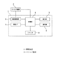
本発明に係る撮像装置及びストロボ装置の一実施形態について、図1〜図6を参酌しつつ、説明する。本実施形態に係る撮像装置1は、図1に示すように、被写体にストロボ光を照射するストロボ装置2を装着可能に構成している。撮像装置1は、被写体を撮影する撮影機能部3と、ストロボ装置2及び撮影機能部3を制御する制御部4と、被写体を撮影した画像などを表示する表示部5と、撮影条件の設定や電源を切り換えるための操作部6と、周辺機器との間で画像データなどを入出力するための周辺I/F7と、ストロボ装置2を発光させて被写体を撮影するためにユーザが操作するシャッター8とを備えている。
An embodiment of an imaging device and a strobe device according to the present invention will be described with reference to FIGS. As shown in FIG. 1, the imaging apparatus 1 according to the present embodiment is configured to be capable of mounting a
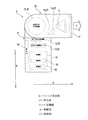
ストロボ装置2は、図2及び図3に示すように、ストロボ本体部9と、ストロボ本体部9に回転可能に連結され、閃光放電管11が収納されて外部へ発光する発光部10と、発光部10を所定の角度に変更可能とする可変機構12と、可変機構12を駆動する駆動部13と、ストロボ本体部9に対する発光部10の角度を検出する角度検出部14と、ストロボ装置を制御する制御部15と、ストロボ本体部9に設けられ、各種設定値を入力したり、各種モードを選択するための操作部16とを備えている。
2 and 3, the
ストロボ本体部9は、矩形状に形成された筐体であり、その上面側に発光部10を回転可能に連結し、その下面側に撮像装置1を連結可能に構成されている。ストロボ本体部9は、正面が撮像装置1の撮影方向A(撮像レンズの光軸方向)を向くように撮像装置1に連結されている。
The strobe
発光部10は、略矩形状に形成された筐体であり、一方の面に閃光放電管11が発光した光が放出する開口部17を備えている。発光部10は、鉛直方向Bに対する開口部17の傾斜角度を変更するなどして、ストロボ光の照射方向Cを変更可能に構成されている。
The
可変機構12は、図4(a)及び図4(b)に示すように、ストロボ本体部9と発光部10とを回転可能に連結している。具体的には、可変機構12は、ストロボ本体部9の幅方向Dに沿って設けられる横軸Xを中心に鉛直方向Bに回転可能な鉛直方向可変機構18と、ストロボ本体部9の上下方向E(高さ方向)に設けられる縦軸Yを中心に水平方向Fに回転可能な水平方向可変機構19とを備えている。
As shown in FIG. 4A and FIG. 4B, the variable mechanism 12 rotatably connects the strobe
鉛直方向可変機構18は、図4(a)に示すように、鉛直方向Bにおける発光部10の角度を変更可能に設けられている。より詳しくは、鉛直方向可変機構18は、通常照射角度(発光部10が通常撮影位置P1にあるときの角度)と、ユーザによって設定され、通常照射角度とは異なる所望照射角度(発光部10がバウンス撮影位置P2にあるときの角度)との間を含む範囲で鉛直方向Bにおける発光部10の角度を変更可能に設けられている。本実施形態においては、鉛直方向可変機構18は、鉛直方向180度の回転角度を有している。
As shown in FIG. 4A, the vertical
水平方向可変機構19は、図4(b)に示すように、水平方向Fにおける発光部10の角度を変更可能に設けられている。本実施形態においては、水平方向可変機構19は、左右方向180度の回転角度を有している。
As shown in FIG. 4B, the horizontal
駆動部13は、図2及び図3に示すように、鉛直方向可変機構18を駆動する鉛直方向駆動部20(図3参照)と、水平方向可変機構19を駆動する水平方向駆動部21(図2参照)とを備えている。
2 and 3, the drive unit 13 includes a vertical direction drive unit 20 (see FIG. 3) for driving the vertical
鉛直方向駆動部20は、図3に示すように、鉛直方向可変機構18を回転させる鉛直方向駆動モータである。水平方向駆動部21は、図2に示すように、水平方向可変機構19を回転させる水平方向駆動モータである。
As shown in FIG. 3, the vertical direction drive unit 20 is a vertical direction drive motor that rotates the vertical
角度検出部14は、発光部10に設けられ、鉛直方向Bにおける発光部10の角度を検出する鉛直方向角度検出部22と、水平方向Fにおける発光部10の角度を検出する水平方向角度検出部23とを備えている。
The angle detection unit 14 is provided in the
鉛直方向角度検出部22および水平方向角度検出部23はたとえばポテンショメーターであって,その回転角に応じた電圧値から,鉛直方向Bにおける発光部10の傾斜角度および水平方向Fにおける発光部10の傾斜角度を検出している。
The vertical angle detector 22 and the horizontal angle detector 23 are, for example, potentiometers. From the voltage value corresponding to the rotation angle, the inclination angle of the
制御部15は、各種演算処理を行う演算部24と、各種情報を記憶する記憶部25とを備えている。制御部15は、CPUで構成されている。記憶部25は、CPU内蔵のRAM又はROM、あるいはCPUに外部接続されたRAM又はROMで構成されている。記憶部25には、後述する連続発光パターンが記憶されている。
The
次に、本実施形態に係る撮像装置1の連続撮影モードについて、図5及び図6を参酌しつつ、説明する。本実施形態に係る連続撮影モードは、シャッター8を1回押すと、複数回の撮像を連続して行うことができる撮像装置1を用い、撮像毎にストロボ装置2にて発光部10の照射方向角度を変更するといった、いわゆるブラケット撮影の一形態である。そのため、ストロボ装置2の制御部15は、撮像毎に発光部10の照射方向角度を変更するモードを有している。
Next, the continuous shooting mode of the imaging apparatus 1 according to the present embodiment will be described with reference to FIGS. 5 and 6. In the continuous shooting mode according to the present embodiment, when the shutter 8 is pressed once, the imaging device 1 that can continuously perform imaging a plurality of times is used, and the irradiation direction of the
なお、本実施形態においては、シャッター8を1回押すと、合計5回の撮像が行われる撮像装置1を用いる。これに伴い、ストロボ装置2は、合計5回の連続発光を行う。そのため、上記した記憶部25に記憶されている連続発光パターンは、図5に示すような5つの照射方向角度を有している。第1の照射方向角度は、同5(a)に示すように、発光部10が被写体方向に向く角度(ストロボ光を被写体に直接照射する)である。第2の照射方向角度は、同図(b)に示すように、発光部10が上方に向く角度(ストロボ本体部9に対して発光部10が鉛直方向Bで上方に90度となる)である。第3の照射方向角度は、同図(c)に示すように、発光部10が上方であって被写体から離れる方向に向く角度(ストロボ本体部9に対して発光部10が鉛直方向Bで上方に120度となる)である。第4の照射方向角度は、同図(d)に示すように、発光部10が被写体に対して右上方に逸れる方向の角度(ストロボ本体部9に対して発光部10が水平方向Fで右方向に45度となり、垂直方向Bで上方に45度となる)である。第5の照射方向角度は、同図(e)に示すように、発光部10が被写体に対して左上方に逸れる方向の角度(ストロボ本体部9に対して発光部10が水平方向Fで左方向に45度となり、垂直方向Bで上方に45度となる)である。第1の照射方向角度を除く第2〜第5の照射方向角度のそれぞれは、いわゆるバウンス撮影となる照射方向角度である。
In this embodiment, when the shutter 8 is pressed once, the imaging device 1 that performs imaging a total of 5 times is used. Along with this, the
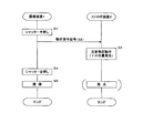
図6に示すように、まず、撮影者は、撮像装置1の撮像レンズを被写体に向けてシャッター8を押す(S1)。すると、撮像装置1の制御部4は、ストロボ装置2に発光指令信号を送信する(S2)。発光指令信号を受けたストロボ装置2の制御部15は、記憶部25に記憶されている連続発光パターンを読み出し、第1の照射方向角度を選択する。これに伴い、ストロボ装置2の制御部15は、駆動部13(鉛直方向駆動部20及び水平方向駆動部21)を制御し、駆動部13(鉛直方向駆動部20及び水平方向駆動部21)は、可変機構12(鉛直方向可変機構18及び水平方向可変機構19)を駆動し、可変機構12(鉛直方向可変機構18及び水平方向可変機構19)は、鉛直方向B及び水平方向Fにおけるストロボ本体部9に対する発光部10の角度を変更する(S3)。そして、ストロボ装置2の制御部15は、発光部10を第1の照射方向角度で発光させる(S4)。これと同時に、撮像装置1の制御部4は、撮影機能部3に1回目の撮像を行わせる(S5)。
As shown in FIG. 6, first, the photographer presses the shutter 8 with the imaging lens of the imaging device 1 facing the subject (S1). Then, the control part 4 of the imaging device 1 transmits a light emission command signal to the strobe device 2 (S2). Upon receiving the light emission command signal, the
ストロボ装置2の制御部15は、1回目の発光を終え、2回目の発光が可能であれば、発光可能信号を撮像装置1に送信する(S6)。発光可能信号を受けた撮像装置1の制御部4は、ストロボ装置2に2回目の発光指令信号を送信する(S7)。これを受けたストロボ装置2の制御部15は、発光部10を第2の照射方向角度にし(S8)、その方向に向けて発光部10を発光させる(S9)。これと同時に、撮像装置1の制御部4は、撮影機能部3に2回目の撮像を行わせる(S10)。
The
そして、これらの処理は、撮像装置1が5回目の撮像を行うまで、すなわち、第1〜第5のそれぞれ照射方向角度でストロボ発光した複数の画像を得るまで行われる(S11〜S25)。 These processes are performed until the image capturing apparatus 1 performs the fifth image capturing, that is, until a plurality of images flashed at the first to fifth irradiation direction angles are obtained (S11 to S25).
以上、本実施形態に係る連続撮影モードによれば、撮影者は、得られた複数の画像の中から気に入った画像、たとえばバウンス撮影の効果が良好に現れている画像を得ることができる。あるいは、撮影者は、その中からストロボ光の好ましい照射条件(発光部10の照射方向角度についての適切条件)を得ることができる。つまり、本実施形態に係る連続撮影モードによれば、ストロボ光の照射条件が異なる複数の画像が得られるため、気に入った画像(あるいはストロボ光の好ましい照射条件)を直ちに得ることができる。 As described above, according to the continuous shooting mode according to the present embodiment, the photographer can obtain a favorite image from among the obtained images, for example, an image in which the effect of the bounce shooting appears well. Alternatively, the photographer can obtain preferable irradiation conditions of the strobe light (appropriate conditions for the irradiation direction angle of the light emitting unit 10). In other words, according to the continuous shooting mode according to the present embodiment, a plurality of images with different strobe light irradiation conditions can be obtained, so that a favorite image (or a preferred strobe light irradiation condition) can be obtained immediately.
ところで、連続撮影モードにおいて、撮像を開始してから撮像を終了するまでの時間(連続撮影所要時間)が長くなることは、被写体の状態が変化する可能性があるため、好ましくない。そのため、連続撮影所要時間は、2秒以内であることが好ましい。連続撮影モードにおいて、時間を占める割合が高いのは、発光部10の照射方向角度変更にかかる時間であるので、連続撮影所要時間を短くするためには、発光部10の照射方向角度変更にかかる時間を短くすればよい。よって、本実施形態においては、駆動部13(鉛直方向駆動部20及び水平方向駆動部21)は、発光部10が1秒に180°移動するように、可変機構12(鉛直方向可変機構18及び水平方向可変機構19)を駆動する。
By the way, in the continuous shooting mode, it is not preferable that the time from the start of imaging to the end of imaging (the time required for continuous shooting) is long because the state of the subject may change. Therefore, it is preferable that the continuous shooting time is within 2 seconds. In the continuous shooting mode, the time occupying a high ratio is the time required for changing the irradiation direction angle of the
なお、本発明に係る撮像装置及びストロボ装置は、上記実施形態に限定されるものではなく、本発明の要旨を逸脱しない範囲内において種々変更を加え得ることは勿論である。 Note that the imaging device and the strobe device according to the present invention are not limited to the above-described embodiments, and it is needless to say that various changes can be made without departing from the gist of the present invention.
例えば、上記実施形態においては、第1〜第5の照射方向角度の組み合わせが連続発光パターンとされている。しかしながら、連続発光パターンはこれに限定されるものではない。各種の照射方向角度を適宜組み合わせて連続発光パターンとすることができる。また、発光回数も5回に限定されるものではなく、2〜4回あるいは6回以上であってもよい。また、発光回数は操作部16によって入力可能であってもよい。なお、連続発光パターンとしては、発光しないことを含むものであってもよい。
For example, in the above embodiment, a combination of the first to fifth irradiation direction angles is a continuous light emission pattern. However, the continuous light emission pattern is not limited to this. Various emission direction angles can be appropriately combined to form a continuous light emission pattern. Further, the number of times of light emission is not limited to 5 times, and may be 2 to 4 times or 6 times or more. Further, the number of times of light emission may be input by the
また、上記実施形態においては、連続発光パターンにおける各照射方向角度は、鉛直方向Bにおける角度と水平方向Fにおける角度とを両方変更するものである。しかしながら、連続発光パターンはこれに限定されるものではない。例えば、垂直方向Bにおける角度でしか発光部10の角度が変更しない連続発光パターンであってもよい。そもそも水平方向Fにおける発光部10の回転構造を有していないストロボ装置であれば、当然この場合に該当する。あるいは、水平方向Fにおける角度でしか発光部10の角度が変更しない連続発光パターンであってもよい。
Moreover, in the said embodiment, each irradiation direction angle in a continuous light emission pattern changes both the angle in the vertical direction B, and the angle in the horizontal direction F. FIG. However, the continuous light emission pattern is not limited to this. For example, it may be a continuous light emission pattern in which the angle of the
また、上記実施形態においては、第2〜第5の照射方向角度として、いわゆるバウンス撮影となる照射方向角度が取り入れられている。すなわち、上記実施形態においては、連続発光パターンは、主としてバウンス撮影を意図している。しかしながら、連続発光パターンはこれに限定されるものではない。例えば、バウンス撮影とはならない照射方向角度のみを組み合わせた連続発光パターンであったり、バウンス撮影となる照射方向角度を一部に取り入れながらも全体に占めるその割合が少ない連続発光パターンであってもよい。 Moreover, in the said embodiment, the irradiation direction angle used as what is called bounce imaging | photography is taken in as a 2nd-5th irradiation direction angle. That is, in the above embodiment, the continuous light emission pattern is mainly intended for bounce shooting. However, the continuous light emission pattern is not limited to this. For example, it may be a continuous light emission pattern that combines only irradiation direction angles that do not become bounce shooting, or a continuous light emission pattern that accounts for a small part of the whole while taking in the irradiation direction angle that becomes bounce shooting. .
また、上記実施形態においては、予め定められた内容で連続発光パターンが構成されている。しかしながら、連続発光パターンはこれに限定されるものではない。例えば、ストロボ装置2の制御部15が都度、ストロボ光の異なる好ましい照射条件を求め、その条件に即して発光部10が発光するといった連続発光パターンであってもよい。一例として、天井を利用したバウンス撮影、壁の第1面を利用したバウンス撮影、壁の第2面を利用したバウンス撮影などで構成される複数回のバウンス撮影を実施するとともに、それぞれに対して事前にストロボ光の好ましい照射条件を求めるといった連続発光パターンが考えられる。
Moreover, in the said embodiment, the continuous light emission pattern is comprised by the predetermined content. However, the continuous light emission pattern is not limited to this. For example, it may be a continuous light emission pattern in which the
あるいは、ストロボ装置2の制御部15がストロボ光の一つの好ましい照射条件を求め、その条件に即して発光部10を発光させるとともに、その条件を中心としてプラス方向及び/又はマイナス方向に条件を変更していくといった連続発光パターンであってもよい。一例として、天井を利用したバウンス撮影において、ストロボ本体部9に対して発光部10が垂直方向Bで上方に45度となるような照射方向がストロボ光の好ましい照射条件であるとした場合、発光部10の角度を35度、40度、45度、50度、55度に切り替えて発光させるといった連続発光パターンが考えられる。
Alternatively, the
また、上記実施形態においては、ストロボ装置2は、撮像装置1から連続して送られてくる発光指令信号に同期して連続発光するようになっている。しかしながら、ストロボ装置2の連続発光方法はこれに限定されるものではない。例えば、撮像装置1において、連続撮影モードにおける撮像タイミングが一定間隔であるならば、この間隔毎にストロボ装置2が発光するようにしてもよい。
In the above-described embodiment, the
また、上記実施形態においては、撮像装置1は、連続撮影モードにおいて、ストロボ装置2から発光可能信号を受けて、次回の撮像を行うようになっている。しかしながら、撮像装置1の連続撮影方法はこれに限定されるものではない。撮像装置1は、ストロボ装置2からなんらの情報を考慮することなく連続撮影を行っていくようにしてもよい。
Further, in the above-described embodiment, the imaging device 1 receives the light emission enable signal from the
また、上記実施形態においては、短期間で連続発光が可能となるよう、ストロボ装置2の主コンデンサに蓄積された電気エネルギを分割して各ストロボ発光に充てるようにしている。しかしながら、ストロボ発光に対するエネルギ供給方法はこれに限定されるものではない。例えば、連続発光における各ストロボ発光の光量を増やしたいならば、連続発光の発光間隔を長くし(言い換えれば、連続撮影モードにおける撮像間隔を長くし)、これにより、発光間隔において主コンデンサに電気エネルギが充電される時間を増やすようにすればよい。
In the above embodiment, the electric energy accumulated in the main capacitor of the
また、上記実施形態においては、鉛直方向角度検出部22や水平方向角度検出部23によって把握される発光部10の鉛直方向Bにおける絶対角度や水平方向Fにおける絶対角度を用いて発光部10の角度制御が行われている。しかしながら、発光部10の角度制御はこれに限定されるものではない。例えば、鉛直方向駆動部20や水平方向駆動部21の制御量あるいは鉛直方向可変機構18や水平方向可変機構19の駆動量をもって発光部10の鉛直方向Bにおける角度や水平方向Fにおける角度を相対的に変更することにより、発光部10の角度制御を行うようにしてもよい。この場合、鉛直方向角度検出部22や水平方向角度検出部23を不要とすることができる。
Moreover, in the said embodiment, the angle of the
また、上記実施形態においては、連続撮影モードとして、シャッター8を1回押せば連続撮影が行われるようになっている。しかしながら、連続撮影モードはこれに限定されるものではない。例えば、連続撮影モードとして、撮像毎にシャッター8の押し操作を要するものであってもよい。 In the above embodiment, as the continuous shooting mode, continuous shooting is performed by pressing the shutter 8 once. However, the continuous shooting mode is not limited to this. For example, as the continuous shooting mode, a pressing operation of the shutter 8 may be required for each imaging.
本発明に係る撮像装置及びストロボ装置は、撮像装置が連続して撮像を行うことに対し、発光部の照射方向角度を変更可能なストロボ装置の制御部が撮像毎に発光部の照射方向角度を変更するモードを有する構成とすることにより、気に入った画像(あるいはストロボ光の好ましい照射条件)を直ちに得ることができることが必要な用途に適用できる。 In the imaging device and the strobe device according to the present invention, while the imaging device continuously performs imaging, the control unit of the strobe device that can change the irradiation direction angle of the light emitting unit changes the irradiation direction angle of the light emitting unit for each imaging. By adopting a configuration having a mode for changing, it is possible to apply to applications where it is necessary to be able to immediately obtain a favorite image (or preferable irradiation condition of strobe light).
1 撮像装置
2 ストロボ装置
4 制御部
8 シャッター
9 ストロボ本体部
10 発光部
12 可変機構
13 駆動部
14 角度検出部
15 制御部
18 鉛直方向可変機構
19 水平方向可変機構
20 鉛直方向駆動部
21 水平方向駆動部
22 鉛直方向角度検出部
23 水平方向角度検出部
25 記憶部
B 鉛直方向
C 照射方向
F 水平方向
DESCRIPTION OF SYMBOLS 1
Claims (4)
撮像装置が連続して撮像を行うことに対し、前記制御部は、撮像毎に前記発光部の照射方向角度を変更するモードを有することを特徴とするストロボ装置。 A strobe main body, a light emitting unit rotatably connected to the strobe main unit, a variable mechanism capable of changing the angle of the light emitting unit, a drive unit that drives the variable mechanism, and a control unit that controls the drive unit A stroboscopic device comprising a control unit and capable of changing an irradiation direction angle of the light emitting unit by the control unit,
The strobe device according to claim 1, wherein the control unit has a mode of changing an irradiation direction angle of the light emitting unit for each imaging while the imaging device continuously performs imaging.
Priority Applications (4)
| Application Number | Priority Date | Filing Date | Title |
|---|---|---|---|
| JP2012099475A JP2013228501A (en) | 2012-04-25 | 2012-04-25 | Strobe device and imaging device |
| PCT/JP2013/002613 WO2013161224A1 (en) | 2012-04-25 | 2013-04-18 | Strobe device and imaging device equipped with strobe device |
| US14/395,536 US20150131257A1 (en) | 2012-04-25 | 2013-04-18 | Strobe device and imaging device equipped with srobe device |
| CN201380021116.7A CN104246602A (en) | 2012-04-25 | 2013-04-18 | Strobe device and imaging device equipped with strobe device |
Applications Claiming Priority (1)
| Application Number | Priority Date | Filing Date | Title |
|---|---|---|---|
| JP2012099475A JP2013228501A (en) | 2012-04-25 | 2012-04-25 | Strobe device and imaging device |
Publications (1)
| Publication Number | Publication Date |
|---|---|
| JP2013228501A true JP2013228501A (en) | 2013-11-07 |
Family
ID=49482572
Family Applications (1)
| Application Number | Title | Priority Date | Filing Date |
|---|---|---|---|
| JP2012099475A Pending JP2013228501A (en) | 2012-04-25 | 2012-04-25 | Strobe device and imaging device |
Country Status (4)
| Country | Link |
|---|---|
| US (1) | US20150131257A1 (en) |
| JP (1) | JP2013228501A (en) |
| CN (1) | CN104246602A (en) |
| WO (1) | WO2013161224A1 (en) |
Cited By (1)
| Publication number | Priority date | Publication date | Assignee | Title |
|---|---|---|---|---|
| JP2016057495A (en) * | 2014-09-10 | 2016-04-21 | キヤノン株式会社 | Imaging system, illumination device, and control method |
Families Citing this family (8)
| Publication number | Priority date | Publication date | Assignee | Title |
|---|---|---|---|---|
| JP6288992B2 (en) * | 2013-08-30 | 2018-03-07 | キヤノン株式会社 | Illumination device and imaging device |
| CN107396000B (en) * | 2015-01-29 | 2019-07-19 | Oppo广东移动通信有限公司 | A kind of light compensation method and device of camera shooting |
| CN104883499B (en) * | 2015-04-30 | 2019-02-05 | Oppo广东移动通信有限公司 | A kind of flash lamp setting method and mobile terminal |
| CN104853111B (en) * | 2015-04-30 | 2018-09-04 | 广东欧珀移动通信有限公司 | A kind of image pickup method and terminal |
| CN105049715B (en) * | 2015-06-30 | 2018-01-23 | 广东欧珀移动通信有限公司 | A kind of flash photographing method and mobile terminal |
| JP6562791B2 (en) * | 2015-09-14 | 2019-08-21 | キヤノン株式会社 | Imaging device, control method thereof, and program |
| JP6789756B2 (en) | 2016-10-24 | 2020-11-25 | キヤノン株式会社 | Lighting device |
| WO2019019006A1 (en) * | 2017-07-25 | 2019-01-31 | 深圳市大疆灵眸科技有限公司 | Photoflash control method, pan-tilt zoom head device, handheld pan-tilt zoom head, and unmanned aerial vehicle |
Citations (5)
| Publication number | Priority date | Publication date | Assignee | Title |
|---|---|---|---|---|
| JP2009163179A (en) * | 2008-01-10 | 2009-07-23 | Fujifilm Corp | Photographing device and method of controlling the same |
| JP2010081481A (en) * | 2008-09-29 | 2010-04-08 | Sony Corp | Imaging apparatus and imaging control method |
| JP2010282186A (en) * | 2009-05-07 | 2010-12-16 | Panasonic Corp | Imaging device |
| JP2011069920A (en) * | 2009-09-24 | 2011-04-07 | Nikon Corp | Illuminator, imaging apparatus and illuminating method |
| JP2011118309A (en) * | 2009-12-07 | 2011-06-16 | Nikon Corp | Image pickup device |
Family Cites Families (2)
| Publication number | Priority date | Publication date | Assignee | Title |
|---|---|---|---|---|
| CN100368926C (en) * | 2003-12-31 | 2008-02-13 | 亚洲光学股份有限公司 | Opening device for flash lamp |
| JP2007065081A (en) * | 2005-08-29 | 2007-03-15 | Sony Corp | Flash unit and imaging device |
-
2012
- 2012-04-25 JP JP2012099475A patent/JP2013228501A/en active Pending
-
2013
- 2013-04-18 US US14/395,536 patent/US20150131257A1/en not_active Abandoned
- 2013-04-18 CN CN201380021116.7A patent/CN104246602A/en active Pending
- 2013-04-18 WO PCT/JP2013/002613 patent/WO2013161224A1/en active Application Filing
Patent Citations (5)
| Publication number | Priority date | Publication date | Assignee | Title |
|---|---|---|---|---|
| JP2009163179A (en) * | 2008-01-10 | 2009-07-23 | Fujifilm Corp | Photographing device and method of controlling the same |
| JP2010081481A (en) * | 2008-09-29 | 2010-04-08 | Sony Corp | Imaging apparatus and imaging control method |
| JP2010282186A (en) * | 2009-05-07 | 2010-12-16 | Panasonic Corp | Imaging device |
| JP2011069920A (en) * | 2009-09-24 | 2011-04-07 | Nikon Corp | Illuminator, imaging apparatus and illuminating method |
| JP2011118309A (en) * | 2009-12-07 | 2011-06-16 | Nikon Corp | Image pickup device |
Cited By (1)
| Publication number | Priority date | Publication date | Assignee | Title |
|---|---|---|---|---|
| JP2016057495A (en) * | 2014-09-10 | 2016-04-21 | キヤノン株式会社 | Imaging system, illumination device, and control method |
Also Published As
| Publication number | Publication date |
|---|---|
| US20150131257A1 (en) | 2015-05-14 |
| CN104246602A (en) | 2014-12-24 |
| WO2013161224A1 (en) | 2013-10-31 |
Similar Documents
| Publication | Publication Date | Title |
|---|---|---|
| JP2013228501A (en) | Strobe device and imaging device | |
| JP2009163179A (en) | Photographing device and method of controlling the same | |
| US7668448B2 (en) | Flash apparatus and imaging apparatus | |
| JP4964028B2 (en) | Imaging device | |
| WO2014030331A1 (en) | Strobe device and imaging device provided with strobe device | |
| JP2013092747A (en) | Stroboscopic device and imaging apparatus equipped with stroboscopic device | |
| JP2014038269A (en) | Stroboscopic device, imaging apparatus and image processing method | |
| JP2011170014A (en) | Stroboscopic device | |
| JP2013178354A (en) | Stroboscopic device and imaging apparatus including stroboscopic device | |
| JP2011030163A (en) | Image pickup apparatus, image pickup method and program | |
| JPWO2013157224A1 (en) | Strobe device irradiation direction angle adjustment method, strobe device, and image pickup device equipped with strobe device | |
| JP6161445B2 (en) | Stroboscope and laryngeal electronic endoscope | |
| WO2013161250A1 (en) | Strobe device and photography device provided with same | |
| JP2007047706A (en) | Illuminator and photographing apparatus | |
| JP2017009932A (en) | Imaging system, lighting device and focus detection method | |
| JP2015173398A (en) | Imaging apparatus, imaging system, imaging method and program | |
| JP2014038267A (en) | Stroboscopic device and imaging apparatus | |
| JP2015194576A (en) | Illumination device | |
| JP6584129B2 (en) | Lighting device | |
| JP2010160217A (en) | Illumination device for photography and imaging device | |
| JP6231271B2 (en) | Electronic endoscope system | |
| JP6118195B2 (en) | Multi-angle image photographing system, rotating table device, photographing device, and multi-angle image photographing method | |
| WO2013161223A1 (en) | Strobe device and image-capturing device provided with strobe device | |
| JP4160587B2 (en) | Stand with camera lighting | |
| JP2006201694A (en) | Lens apparatus |
Legal Events
| Date | Code | Title | Description |
|---|---|---|---|
| A711 | Notification of change in applicant |
Free format text: JAPANESE INTERMEDIATE CODE: A711 Effective date: 20141003 |
|
| A621 | Written request for application examination |
Free format text: JAPANESE INTERMEDIATE CODE: A621 Effective date: 20150423 |
|
| A131 | Notification of reasons for refusal |
Free format text: JAPANESE INTERMEDIATE CODE: A131 Effective date: 20160301 |
|
| A02 | Decision of refusal |
Free format text: JAPANESE INTERMEDIATE CODE: A02 Effective date: 20161115 |