JP6288936B2 - Cancer diagnostic equipment - Google Patents
Cancer diagnostic equipment Download PDFInfo
- Publication number
- JP6288936B2 JP6288936B2 JP2013089515A JP2013089515A JP6288936B2 JP 6288936 B2 JP6288936 B2 JP 6288936B2 JP 2013089515 A JP2013089515 A JP 2013089515A JP 2013089515 A JP2013089515 A JP 2013089515A JP 6288936 B2 JP6288936 B2 JP 6288936B2
- Authority
- JP
- Japan
- Prior art keywords
- raman scattering
- visible light
- image
- light
- diagnostic apparatus
- Prior art date
- Legal status (The legal status is an assumption and is not a legal conclusion. Google has not performed a legal analysis and makes no representation as to the accuracy of the status listed.)
- Expired - Fee Related
Links
Images


Description
本発明は、癌診断装置に関する。 The present invention relates to a cancer diagnostic apparatus.
癌の診断に関しては種々の提案がなされており、例えば、特表2003−507088号公報(特許文献1)では、測定する組織に光源からのレーザ光を当て、レイリー散乱光からラマン散乱光をスペクトル分離することにより、悪性腫瘍の疑いのある生物組織のラマン散乱光強度と隣接する正常な生物組織からのラマン散乱光強度との間の実質的な差を疾病の存在または危険として評価することが提案されている。また、特開2002−5835号公報(特許文献2)では、ラマンスペクトルを用いた正常組織及び癌組織の弁別において、試料に照射する励起光として、Nd:YAGレーザ光源10からの波長1064nmのパルス状の近赤外光を用い、分光器で分光されて光検出器31で検出されるラマン散乱光の計数について、励起光を検出するフォトダイオード16からの励起光検出信号によって、同時計数回路で励起光と同期させて計数することによって、ラマンスペクトルでのバックグラウンド光の強度を低減することが提案されている。
Various proposals have been made regarding the diagnosis of cancer. For example, in Japanese Translation of PCT International Publication No. 2003-507088 (Patent Document 1), a laser beam from a light source is applied to a tissue to be measured, and Raman scattered light is spectrumd from Rayleigh scattered light. By separating, the substantial difference between the Raman scattered light intensity of the biological tissue suspected of being malignant and the Raman scattered light intensity from the adjacent normal biological tissue can be evaluated as the presence or risk of the disease. Proposed. In Japanese Patent Laid-Open No. 2002-5835 (Patent Document 2), a pulse having a wavelength of 1064 nm from an Nd: YAG
しかしながら、より使いやすい癌診断装置に関してはさらに検討すべき課題が多い。 However, there are many problems that should be further studied regarding a cancer diagnostic apparatus that is easier to use.
本発明の課題は、上記に鑑み、より使いやすい癌診断装置を提案することにある。 In view of the above, an object of the present invention is to propose a cancer diagnostic apparatus that is easier to use.
上記課題を達成するため、本発明は、可視光域のフィルタおよびラマン散乱検出フィルタを設けたCIGSイメージセンサを有する癌診断装置を提供する。これによって、CIGSセンサの広い感度域を利用して対象の可視光撮像およびラマン散乱検出を行うことができる。 In order to achieve the above object, the present invention provides a cancer diagnostic apparatus having a CIGS image sensor provided with a visible light range filter and a Raman scattering detection filter. Thereby, visible light imaging and Raman scattering detection of an object can be performed using a wide sensitivity range of the CIGS sensor.
本発明の具体的な特徴によれば、ラマン散乱検出フィルタは、ラマン散乱光を選択的に透過させる測定用赤外フィルタおよびラマン散乱光がない近接域の赤外光を選択的に透過させる参照用赤外フィルタを含む。これによって、レイリー散乱をカットするとともに適格なラマン散乱の検出が可能となる。 According to a specific feature of the present invention, the Raman scattering detection filter is a measurement infrared filter that selectively transmits Raman scattered light, and a reference that selectively transmits infrared light in the vicinity without Raman scattered light. Infrared filter for use. This makes it possible to cut Rayleigh scattering and detect appropriate Raman scattering.
他の具体的な特徴によれば、癌診断装置は可視光域の照明光源およびラマン散乱用光源を有し、CIGSセンサは可視光域の照明光源およびラマン散乱用光源に基づき可視光像の撮像とラマン散乱の検出を行う。より具体的な特徴によれば、可視光域の照明光源および前記ラマン散乱用光源は時分割で対象に照射される。他の具体的な特徴によれば、可視光域の照明光源は時分割で点灯される複数色の光源を含み、可視光域のフィルタはこれら複数色の光源の光をいずれも透過させる。別の具体的な特徴によれば、可視光域のフィルタは複数色を選択的に透過させる。 According to another specific feature, the cancer diagnostic apparatus has an illumination light source in the visible light region and a light source for Raman scattering, and the CIGS sensor captures a visible light image based on the illumination light source in the visible light region and the light source for Raman scattering. And detection of Raman scattering. According to a more specific feature, the illumination light source in the visible light region and the light source for Raman scattering are irradiated onto the object in a time division manner. According to another specific feature, the illumination light source in the visible light region includes a plurality of color light sources that are lighted in a time-sharing manner, and the visible light region filter transmits all of the light of the plurality of color light sources. According to another specific feature, the visible light range filter selectively transmits multiple colors.
他の具体的な特徴によれば、癌診断装置にはラマン散乱検出フィルタを設けたCIGSイメージセンサの出力を基準値として記憶する記憶部が設けられる。これによって、例えば予備測定により基準値を求め、これを基準として本測定を行うことができる。より具体的な特徴によれば、記憶部は、ラマン散乱検出フィルタを設けたCIGSイメージセンサによる複数の測定値の平均値を基準値として記憶する。 According to another specific feature, the cancer diagnostic apparatus is provided with a storage unit that stores an output of a CIGS image sensor provided with a Raman scattering detection filter as a reference value. Thereby, for example, a reference value can be obtained by preliminary measurement, and the main measurement can be performed based on the reference value. According to a more specific feature, the storage unit stores an average value of a plurality of measurement values obtained by the CIGS image sensor provided with the Raman scattering detection filter as a reference value.
他の具体的な特徴によれば、CIGSイメージセンサによる可視光像の表示において、ラマン散乱の検知部分を特定する重畳表示が行われる。これによって、可視光像に基づいてラマン散乱測定部分を適確に知ることができる。 According to another specific feature, in the display of the visible light image by the CIGS image sensor, the superimposed display for specifying the detection portion of the Raman scattering is performed. Thereby, the Raman scattering measurement part can be accurately known based on the visible light image.
本発明の他の特徴によれば、撮像レンズを有し、可視光画像の撮像およびラマン散乱の測定が可能であるとともに、可視光像の表示においてラマン散乱の検知部分を特定する重畳表示を行い、重畳表示位置は、撮像レンズのフォーカス調節に応じて変化させられる癌診断装置が提供される。これによって、可視光像に基づいてラマン散乱測定部分を適確に知ることができるとともに、ラマン散乱の検知部分が撮像レンズの光軸上になくてもフォーカス調節にかかわらずラマン散乱測定部分を正確に重畳表示できる。 According to another feature of the present invention, an imaging lens is provided, which is capable of capturing a visible light image and measuring Raman scattering, and performing a superimposed display that identifies a detection portion of Raman scattering in displaying a visible light image. A cancer diagnostic apparatus is provided in which the superimposed display position can be changed according to the focus adjustment of the imaging lens. As a result, the Raman scattering measurement part can be accurately known based on the visible light image, and the Raman scattering measurement part can be accurately detected regardless of the focus adjustment even if the Raman scattering detection part is not on the optical axis of the imaging lens. Can be superimposed on the screen.
本発明の他の特徴によれば、撮像レンズを有し、可視光画像の撮像およびラマン散乱の測定が可能であるとともに、可視光像の表示においてラマン散乱の検知部分を特定する重畳表示を行い、重畳表示位置は、撮像レンズのズーミングに応じて変化させられる癌診断装置が提供される。これによって、可視光像に基づいてラマン散乱測定部分を適確に知ることができるとともに、ラマン散乱の検知部分が撮像レンズの光軸上になくてもズーミングにかかわらずラマン散乱測定部分を正確に重畳表示できる。 According to another feature of the present invention, an imaging lens is provided, which is capable of capturing a visible light image and measuring Raman scattering, and performing a superimposed display that identifies a detection portion of Raman scattering in displaying a visible light image. A cancer diagnostic apparatus is provided in which the superimposed display position can be changed according to zooming of the imaging lens. This makes it possible to accurately know the Raman scattering measurement part based on the visible light image, and accurately detect the Raman scattering measurement part regardless of zooming even if the Raman scattering detection part is not on the optical axis of the imaging lens. Superimposed display.
本発明の他の特徴によれば、可視光画像の撮像およびラマン散乱の測定を時分割で行うとともに、可視光像の表示においてラマン散乱の検出時においても可視光像の表示を継続する癌診断装置が提供される。これによって、可視光画像の撮像およびラマン散乱の測定を互いの干渉なく行うことができるとともに、ラマン散乱の測定に中断されることなく可視光画像の表示を行うことができる。 According to another feature of the present invention, a cancer diagnosis that captures a visible light image and measures Raman scattering in a time-sharing manner and continues displaying the visible light image even when detecting the Raman scattering in the visible light image display. An apparatus is provided. Thereby, the imaging of the visible light image and the measurement of the Raman scattering can be performed without mutual interference, and the visible light image can be displayed without being interrupted by the measurement of the Raman scattering.
上記のように、本発明によれば、ラマン散乱を利用したより使いやすい癌診断装置を提供することができる。 As described above, according to the present invention, it is possible to provide an easier-to-use cancer diagnostic apparatus using Raman scattering.
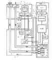
図1は、本発明の実施の形態に係る内視鏡の実施例の全体構成を示す模式図である。実施例の内視鏡は、統括ユニット2によって制御されており、統括ユニット2は、観察画像等を表示するためのモニタ4を有する。操作ユニット6は接続ケーブル8によって統括ユニット2に接続されており、接続ケーブル8には光源光を伝達するための光ファイバーおよび電気信号を伝達するための信号線などが通っている。操作ユニット6はこれを操作する医師の手に握られるもので、胃などに挿入される挿入部10が延びており、その先端は、撮像光学系や照明光学系が配置される先端部12となっている。実施例の内視鏡は、胃などの画像を観察する通常の機能と併せ、胃などにレーザビームを照射してそのラマン散乱を検知することで正常組織と癌組織とを弁別するよう構成されている。
FIG. 1 is a schematic diagram illustrating an overall configuration of an example of an endoscope according to an embodiment of the present invention. The endoscope of the embodiment is controlled by the overall unit 2, and the overall unit 2 has a
図2は、図1の実施例における内視鏡の全体構成のブロック図であり、図1と対応する部分には同一の番号を付す。統括ユニット2には内視鏡全体を統括制御する制御部14が設けられている。記憶部16は、制御部14の動作に必要な制御プログラムを記憶するとともに、測定データを蓄積記憶する。また、制御に関連するデータを一時的に記憶する。
FIG. 2 is a block diagram of the overall configuration of the endoscope in the embodiment of FIG. 1, and parts corresponding to those in FIG. The overall unit 2 is provided with a
画像処理部18は、先端部2で撮像された内視鏡画像を処理し、新たなカラー画像が得られると表示メモリ20の表示用画像データを更新する。そしてモニタ4は、表示メモリ20の表示用画像データに基づき画像表示を行う。画像処理部18は、また、ラマン散乱検知のための光源ビーム照射位置を内視鏡画像に重畳表示し、内視鏡画像のどの位置に光源ビームが照射されているかを表示する。後述するように、内視鏡画像の撮像とラマン散乱の検出は時分割で行われるが、表示メモリ20は、ラマン散乱検出のために内視鏡画像の撮像が行われない時間帯においても、最新の内視鏡画像を保持し、モニタ4での表示を継続する。
The
統括ユニット2には、さらに光源部22が設けられており、制御部14は、内視鏡画像撮像時間帯において赤色LED24、緑色LED26および青色LED28を順次発光させるよう制御する。光源部22には、さらに赤外光(例えば1056nm)を発生するラマン散乱用光源レーザ30が設けられており、制御部14は、ラマン散乱検出のため時間帯においてラマン散乱用光源レーザ30を発光させるよう制御する。
The overall unit 2 is further provided with a
先端部12には、フォーカス調節およびズーミングが可能な撮像レンズ32が設けられており、CIGSイメージセンサ34は、撮像レンズ32による可視光像を撮像する。CIGSイメージセンサ34は、銅、インジウム、ガリウムおよびセレンよりなる多結晶のCIGS系薄膜を用いた光電センサであって、その組成制御によりバンドギャップを変化させることで吸収波長域を制御し、400nm付近から1300nm付近にわたる広い感度域を持たせたものである。これによって、CIGSイメージセンサ34は赤色LED24、緑色LED26および青色LED28が順次発光しているタイミングの画像出力により可視光像の撮像を行うことができるとともに、後述のように例えば1056nmの光源光に対する1258nmのラマン散乱光を検知するセンサとしても機能する。
The
撮像レンズ32は、オートフォーカス信号に基づいて機能するフォーカス駆動部36により自動的にフォーカス調節されるとともに、手動操作信号に基づいて機能するズーム駆動部38により手動でズーム操作される。赤色LED24、緑色LED26および青色LED28から順次発光される可視照明光は、照明用光ファイバー40内を導かれて照明光学系42から撮像レンズ32の最広角の視野範囲を照明する。また、ラマン散乱用光源レーザ30から射出されたレーザ光は、レーザ用光ファイバー44内を導かれてビーム照射光学系46から撮像レンズ32の光軸48と平行に光源ビームを照射する。
The
照明用光ファイバー40およびレーザ用光ファイバー44が経由している操作ユニット6には、操作部50が設けられており、この操作部を手動操作することによりズーム手動操作信号がズーム操作部38に伝達される。また、操作ユニット6のオートフォーカス処理部52は、緑色LED26が照射された時点のCIGSイメージセンサ34の画像出力に基づいてそのコントラストを検出処理し、制御部14の制御に基づいてコントラストがより大きくなるよう撮像レンズ32を駆動するためのオートフォーカスをフォーカス駆動部36に伝達する。さらに、操作ユニット6のラマン散乱処理部54は、ラマン散乱用光源レーザ30からレーザビームが射出されるタイミングにおけるCIGSイメージセンサ34の出力を処理し、これを制御部14に伝える。なお、赤色LED24、緑色LED26および青色LED28が順次発光しているタイミングにおけるCIGSイメージセンサ34の出力も操作ユニット6を経由して行われる。
The
なお、上述のように、操作ユニット6と統括ユニット2との間の光ファイバー40、44の接続および電気信号を伝達するための信号線の接続は接続ケーブル8を通して行われる。また、操作ユニット6と先端部12との間の光ファイバー40、44の接続および電気信号を伝達するための信号線の接続は挿入部10を通して行われる。また、挿入部10の端部近傍には、挿入部10に対する先端部12の向きを自由に変更させるための屈曲機構56が設けられており、操作ユニット6の操作部50の手動操作に基づく屈曲制御信号が伝達される。
Note that, as described above, the connection of the
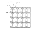
図3は、図2で示した実施例におけるCIGSイメージセンサ34のカラーフィルタ配列図である。CIGSイメージセンサ34においては、赤外域をカットし可視光域を透過させる可視光域フィルタV11、V22、ラマン散乱光を選択的に透過させるために1258nmを中心として±4nmの半値幅を持つ狭帯域の測定用赤外フィルタIR12、およびラマン散乱光がない近接域の赤外光を選択的に透過させるために1271nmを中心として±4nmの半値幅を持つ狭帯域の参照用赤外フィルタRref21が図示のように配列され、これを一つの単位として繰り返す配列となっている。本発明のCIGS撮像センサは、上記のように可視光域から赤外光にわたる広い分光感度域をもつため、このように一つのセンサに可視光および赤外光のカラーフィルタを設け、可視光像の検知とラマン散乱光の測定を行うことができる。
FIG. 3 is a color filter array diagram of the
上記のようにともに狭帯域の測定用赤外フィルタIR12および参照用赤外フィルタRref21を用いることにより、1056nmのラマン散乱用光源レーザ30の光源光に基づくレイリー散乱光を除去することができる。そして、ラマン散乱光の測定にあたっては、測定用赤外フィルタIR12が設けられている全画素の出力を加算するとともに、参照用赤外フィルタRref21が設けられている全画像の出力が加算し、両加算値の差をとることで、1258nmにおけるラマン散乱光の強度を検出することができる。
By using the narrow-band measurement infrared filter IR12 and the reference infrared filter Rref21 as described above, the Rayleigh scattered light based on the light source light of the 1056 nm Raman scattering
なお、可視光像の形成にあたっては、測定用赤外フィルタIR12、参照用赤外フィルタRref21が設けられている画像についても、その周囲にある可視光域フィルタが設けられている画素のデータによって補間を行うことにより画素信号を得る。この補間は、赤色LED24、緑色LED26および青色LED28が順次発光している各タイミングにおいてそれぞれ赤色画像、緑色画像および青色画像について行う。
In forming a visible light image, an image provided with the measurement infrared filter IR12 and the reference infrared filter Rref21 is also interpolated by data of pixels around which a visible light region filter is provided. To obtain a pixel signal. This interpolation is performed for the red image, the green image, and the blue image at each timing when the
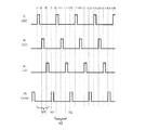
図4は、図2で示した実施例における赤色LED24、緑色LED26および青色LED28の発光、並びにラマン散乱用光源レーザ30から射出されるレーザビームの測定対象への照射タイミングの関係を示すタイミングチャートである。図4に示すように、t1で開始される緑色LED26の発光に基づく緑色画像、t3で開始される赤色LED24の発光に基づく赤色画像、およびt5で開始される青色LEDの発光に基づく青色画像によって、V1で示す1フレームの可視光カラー画像が作成される。厳密に言えば各色の発光に時間差があるので各色の画像は同一時間のものではないが、時間差は僅少なので高速で動く被写体でない限りこのような時分割による各色画像の取得でも問題はない。同様にして、t9で開始される緑色LED26の発光に基づく緑色画像、t11で開始される赤色LED24の発光に基づく赤色画像、およびt13で開始される青色LEDの発光に基づく青色画像によって、V2で示す1フレームの可視光カラー画像が作成される。以下同様にして1フレームのカラー画像が作成され、個々のカラー動画は静止画としても記録できるとともに、これらを繋げてカラー動画としても記録できる。なお、これらのカラー処理は、図2に示した画像処理部18で行われる。
FIG. 4 is a timing chart showing the relationship between the light emission of the
一方、ラマン散乱の測定については、図4に示すように、t7で開始されるラマン散乱用光源レーザ30から射出されるレーザビームの測定対象への照射に基づき、測定用赤外フィルタIR12に対応する全画素の出力を加算するとともに、同タイミングにおける参照用赤外フィルタRref21に対応する全画像の出力を加算し、両加算値の差をとることでラマン散乱強度R1が求められる。同様にt15で開始されるレーザビームの照射に基づき、測定用赤外フィルタIR12に対応する全画素の出力を加算するとともに、同タイミングにおける参照用赤外フィルタRref21に対応する全画像の出力を加算し、両加算値の差をとることでラマン散乱強度R2が求められる。以下同様にして可視光像の撮像と並行して時分割でラマン散乱強度を連続して測定することができる。従って、可視光像により対処を測定しながら、可視光像の中に重畳表示されるレーザ照射位置についてラマン散乱強度を測定することができる。そして可視光の観察により測定位置を変えながら測定を続けることができる。
On the other hand, as shown in FIG. 4, the measurement of Raman scattering corresponds to the measurement infrared filter IR12 based on the irradiation of the laser beam emitted from the Raman scattering
図5は、図2で示した実施例における内視鏡の撮像光学系の断面図およびモニタ表示図であり、モニタ表示におけるビーム位置の表示を説明するためのものである。図2と対応する部分には同一の番号を付し、必要のない限り説明を省略する。図5(A)は、ズームのワイド端(最も広角側)における最長撮影距離での内視鏡の撮像光学系の断面を模式的に示したものである。胃壁等の撮像および測定の対象58の像がCIGSイメージセンサ34上に結像しているとともに、照射光学系46から撮像レンズ32の光軸48と平行に光源ビーム60が対象58に照射されている。
FIG. 5 is a cross-sectional view and a monitor display diagram of the imaging optical system of the endoscope in the embodiment shown in FIG. 2, for explaining the display of the beam position in the monitor display. Parts corresponding to those in FIG. 2 are denoted by the same reference numerals, and description thereof is omitted unless necessary. FIG. 5A schematically shows a cross section of the imaging optical system of the endoscope at the longest shooting distance at the wide end (most wide-angle side) of zoom. An image of an imaging and
図5(B)は、図5(A)の状態においてモニタ4に表示される画面を示しており、図2で示した実施例における内視鏡の撮像光学系の断面図およびモニタ表示図であり、モニタ4の中に、胃壁等の対象58が表示されている。モニタ4にはさらに、画像の中心を示す十字線62および光源ビーム60の照射位置マーク64が重畳表示されている。これによって、モニタ4に表示されている対象58のどこに光源ビーム60が照射されているかがわかる。このような表示により、対象58を観察しながら所望の位置に光源ビーム60を照射してその位置におけるラマン散乱の測定を行うことができる。
FIG. 5B shows a screen displayed on the
図5(C)は、ズームをワイド端のままにして撮像光学系を対象58に近づけた状態の断面を模式的に示している。このように対象に近づくことによって、対象58の一部の像がCIGSイメージセンサ34上に拡大して結像する。なお、撮像レンズ32はオートフォーカス機能によりフォーカス調節されて繰り出されている。この状態においても照射光学系46から照射される光源ビーム60と撮像レンズ32の光軸48の位置関係は変わらないが、撮像範囲が狭まることにより、光源ビーム60は撮像範囲のより外側寄りに照射されることになる。図5(D)は、図5(C)の状態においてモニタ4に表示される画面を示しており、対象58が拡大されて表示されるとともに、図5(B)と比較して光源ビーム60の照射位置マーク64が十字線62から離れ、モニタ4の視野内のより外側寄りに移動して表示される。
FIG. 5C schematically shows a cross section in a state in which the image pickup optical system is brought close to the
図5(E)は、撮影距離を図5(A)の状態のままにして、撮像レンズ32を望遠側にズームアップした状態の断面を模式的に示している。このようにズーミングを行うことによっても対象58の一部の像がCIGSイメージセンサ34上に拡大して結像する。この場合、撮像レンズ32の焦点距離が長くなるようズーム駆動部が撮像レンズ32を駆動する。この状態においても照射光学系46から照射される光源ビーム60と撮像レンズ32の光軸48の位置関係は変わらないが、図5(C)と同様にして撮像範囲が狭まることにより、光源ビーム60は撮像範囲のより外側寄りに照射されることになる。図5(F)は、図5(E)の状態においてモニタ4に表示される画面を示しており、図5(D)と同様にして対象58が拡大されて表示されるとともに、図5(B)と比較して光源ビーム60の照射位置マーク64が十字線62から離れ、モニタ4の視野内のより外側寄りに移動して表示される。以上、図5では、典型的な状態を示したが、撮影距離の変化および撮像レンズ32のズーミングにより所望の倍率での撮像が可能となる。そして、図、図5(B)、図5(D)および図5(E)に示したようなモニタ4の視野内における照射位置マーク64の移動は、ズーミングにおける撮像レンズの焦点距離情報およびフォーカス駆動部における撮像レンズのフォーカス調節状態の情報により行うことができる。
FIG. 5E schematically shows a cross section in a state where the
図6は、図5(B)で示したモニタ4の表示範囲を胃壁等の対象58の比較的広範囲とともに示した模式図であり、先端部12を屈曲させることにより対象58の比較的広範囲をスキャンして予備測定する様子を示している。このスキャンによる予備測定は、内視鏡を予備測定モードに設定し、モニタ4に表示される対象58を観察しながら可視画像としては正常に見える部分を、例えば図6における表示範囲4aから4bに移動させることに相当する。このようなスキャンによる予備測定によって、光源ビームは照射位置マーク64aから64bに軌跡64cを経由して移動する。この間、ラマン散乱処理部54はCIGSイメージセンサ34の出力に元づいてラマン散乱強度を繰り返し実測し、これらを蓄積記憶してその平均値を測定の基準値として設定記憶する。測定の初期においてこのような予備測定に基づいて基準値を求めることにより、この実測による基準値を正常組織のラマン散乱強度とみなして目的部分を本測定した際のラマン散乱強度と比較することができ、本測定における目的部分の組織が正常か否かを判断することができる。
FIG. 6 is a schematic diagram showing the display range of the
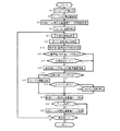
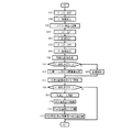
図7は、図2で示した実施例における内視鏡の制御部14の動作の基本フローチャートである。測定開始操作を行うとフローがスタートし、ステップS2で、撮像レンズ32をズームのワイド端に初期設定するとともに、ステップS4でフォーカス初期位置(例えば比較的撮影距離が長く焦点深度も深い位置)の設定を行う。次いでステップS6において、以上のズーム設定およびフォーカス設定に基づき、光源ビーム照射位置マーク64をモニタ4内で重畳表示するためのデータの初期値を設定する。以上の諸初期設定の後、ステップSS8で初期方向(例えば撮影距離を短くする方向)へのフォーカス駆動を開始する。実施例のオートフォーカスはコントラスト方式なので、まず撮像レンズ32を駆動してみてコントラストの変化を見ないと焦点合わせができないからである。
FIG. 7 is a basic flowchart of the operation of the
そしてステップS10で可視光LED照明下での可視光撮像処理を行う。これにより視野内の可視光像が得られるとともにオートフォーカスのためのコントラスト情報が得られる。ステップS10での可視光撮像処理の詳細は後述する。さらにステップS12でラマン散乱用光源レーザによる光源ビーム照射下でのラマン散乱検出処理を行い、検出値を得る。ステップS12でのラマン散乱検出処理の詳細についても後述する。 In step S10, visible light imaging processing under visible light LED illumination is performed. As a result, a visible light image in the field of view can be obtained, and contrast information for autofocus can be obtained. Details of the visible light imaging process in step S10 will be described later. In step S12, a Raman scattering detection process is performed under irradiation of a light source beam by a Raman scattering light source laser to obtain a detection value. Details of the Raman scattering detection process in step S12 will also be described later.
ステップS10およびステップS12でそれぞれ一回ずつの可視光撮像およびラマン散乱の検出値が得られるとステップS14に進み、ラマン測定の検出値から基準値(実測値がない場合は所定の初期値)を引き、測定値として記録する。次にステップS16では基準値と検出値の差の絶対値が所定値以下であるかどうかがチェックされ、差の絶対値が所定値以下であればステップS18に進んで予備測定モードかどうかチェックする。そして予備測定モードであればステップS20に進んで今回の検出値を加入して平均を取り直す基準値の再演算を行い、ステップS22に移行する。後述のようにステップS10からステップS20の処理は図6に示したような予備測定において繰り返されるが、この繰り返しの中で実測平均に基づく基準値が設定される。ステップS16で基準値と測定値の絶対値の差が所定値以上であったとき、またはステップS18で予備測定モードでないことが確認されたときは今回の検出値を基準値に反映させることなく直接ステップS22に移行する。 When the detection values of visible light imaging and Raman scattering are obtained once each in step S10 and step S12, the process proceeds to step S14, and a reference value (a predetermined initial value when there is no actual measurement value) is determined from the detection value of Raman measurement. And record as measured value. Next, in step S16, it is checked whether or not the absolute value of the difference between the reference value and the detected value is equal to or smaller than a predetermined value. If the absolute value of the difference is equal to or smaller than the predetermined value, the process proceeds to step S18 to check whether or not the preliminary measurement mode. . If it is the preliminary measurement mode, the process proceeds to step S20 to recalculate the reference value for adding the current detection value and taking the average again, and the process proceeds to step S22. As will be described later, the processing from step S10 to step S20 is repeated in the preliminary measurement as shown in FIG. 6, and a reference value based on the actual measurement average is set in this repetition. If the difference between the absolute value of the reference value and the measured value is greater than or equal to the predetermined value in step S16, or if it is confirmed in step S18 that it is not the preliminary measurement mode, the detected value of this time is directly reflected on the reference value. Control goes to step S22.
ステップS22では、前回の撮像の可視光像に比べ今回撮像の可視光像のコントラストが低下しているか否かチェックする。そしてコントラストの低下がなければステップSステップS24に進み、コントラストの変化があったか否かチェックする。変化があった場合は、フォーカス駆動によりコントラストが高くなったことを意味するのでその方向へのフォーカス駆動を継続してステップS26に進む。一方、ステップS22でコントラストの低下が検知されたときはピントが外れる方向に撮像レンズがフォーカス駆動されていることを意味するので、ステップS28に移行し、フォーカス駆動を逆転させてステップS26に移行する。また、ステップS24でコントラストに変化がないことが確認されたときは、コントラストがピークでありピントが合ったことを意味するのでステップS30に進みフォーカス駆動を停止してステップS26に移行する。ステップS26では、いずれの場合も、新たなフォーカス調節位置に基づき光源ビーム照射位置重畳データを更新してステップS32に移行する。 In step S22, it is checked whether or not the contrast of the visible light image captured this time is lower than the visible light image captured this time. If there is no decrease in contrast, the process proceeds to step S24, where it is checked whether there is a change in contrast. If there is a change, it means that the contrast has increased due to the focus drive, so the focus drive in that direction is continued and the process proceeds to step S26. On the other hand, if a decrease in contrast is detected in step S22, it means that the imaging lens is being driven in the out-of-focus direction. Therefore, the process proceeds to step S28, the focus drive is reversed, and the process proceeds to step S26. . If it is confirmed in step S24 that there is no change in contrast, it means that the contrast is at the peak and the camera is in focus. Therefore, the process proceeds to step S30, the focus drive is stopped, and the process proceeds to step S26. In any case, in step S26, the light source beam irradiation position superimposition data is updated based on the new focus adjustment position, and the process proceeds to step S32.
なお、後述のようにステップS22、S24、S28およびS30のオートフォーカス制御は繰り返し行われる。この繰り返しの中で、ステップS30でフォーカス駆動が停止された後にステップS22に至り、ここでコントラストの低下がないことが確認されてステップS24でもコントラスト変化が確認されなかった場合はピントが合った状態が継続していることを意味する。この場合、ステップS30ではフォーカス駆動停止が継続され、ステップS26でのデータ更新でも結果的には同じデータが継続される。また、ステップS30でフォーカス駆動が停止された後にステップS22に至り、ここでコントラストの低下が確認されたときは、ステップS28でフォーカス駆動が再開される。その方向は停止前と逆方向となるが、これが不適当であれば次の繰り返しの中のステップS22でさらにコントラストが低下することが検知されるので再度ステップS28に至り、フォーカス駆動方向が訂正される。 As will be described later, the autofocus control in steps S22, S24, S28 and S30 is repeated. In this repetition, after the focus drive is stopped in step S30, the process proceeds to step S22, where it is confirmed that there is no decrease in contrast and no change in contrast is confirmed in step S24. Means that is continuing. In this case, the focus drive stop is continued in step S30, and as a result, the same data is continued even in the data update in step S26. Further, after the focus drive is stopped in step S30, the process proceeds to step S22, and when it is confirmed that the contrast is lowered, the focus drive is resumed in step S28. The direction is opposite to the direction before the stop, but if this is inappropriate, it is detected that the contrast further decreases in step S22 in the next iteration, so step S28 is reached again, and the focus drive direction is corrected. The
ステップS32では、ズーム操作が行われたか否かをチェックする。そしてズーム操作があればステップS34に進み、ズーム操作の結果の新たな焦点距離に基づき光源ビーム照射位置重畳データを更新してステップS36に移行する。一方ステップS32でズーム操作が確認されないときは、直接ステップS36に移行する。 In step S32, it is checked whether or not a zoom operation has been performed. If there is a zoom operation, the process proceeds to step S34, the light source beam irradiation position superimposition data is updated based on the new focal length as a result of the zoom operation, and the process proceeds to step S36. On the other hand, when the zoom operation is not confirmed in step S32, the process directly proceeds to step S36.
ステップS36では、測定停止操作が行われたかい否かチェックし、操作が確認されないときはステップS10に戻る。そしてステップS36で測定停止操作が確認されない限り、ステップS10からステップS36を繰り返し、可視光像の撮像とラマン散乱の測定を継続する。 In step S36, it is checked whether or not a measurement stop operation has been performed. If the operation is not confirmed, the process returns to step S10. Then, unless a measurement stop operation is confirmed in step S36, steps S10 to S36 are repeated, and visible light image capturing and Raman scattering measurement are continued.
図8は、図7のステップS10の可視光撮像処理およびステップS12のラマン散乱検出処理の詳細を示すフローチャートである。図7においてステップS8からステップS10に移行すると、図8のステップS42となり、緑色LED26を点灯させるとともにステップS44でCIGSイメージセンサ34の可視光域フィルタが設けられた画素の出力を緑色画像として画像処理部18に取り込む。そして、ステップS46では取り込んだ緑色画像のコントラストを検出して記憶する。
FIG. 8 is a flowchart showing details of the visible light imaging process in step S10 and the Raman scattering detection process in step S12 in FIG. In FIG. 7, when the process proceeds from step S8 to step S10, the process proceeds to step S42 in FIG. 8, in which the
次いで、ステップS48では、赤色LED24を点灯させるとともにステップS50でCIGSイメージセンサ34の可視光域フィルタが設けられた画素の出力を赤色画像として画像処理部18に取り込む。同様に、ステップS52では、青色LED28を点灯させるとともにステップS54でCIGSイメージセンサ34の可視光域フィルタが設けられた画素の出力を青色画像として画像処理部18に取り込み、ステップS56に移行する。
Next, in step S48, the
ステップS56では、上記のようにして取り込まれた緑色画像、赤色画像および青色画像のそれぞれについて、測定用赤外フィルタおよび参照用赤外フィルタが設けられた画素についての補間を行うとともに、補間後の緑色画像、赤色画像および青色画像に基づいて可視光画像を得、これを記録する。 In step S56, for each of the green image, the red image, and the blue image captured as described above, interpolation is performed for the pixels provided with the measurement infrared filter and the reference infrared filter, and after the interpolation. A visible light image is obtained based on the green, red and blue images and recorded.
次いで、ステップS58では、ラマン散乱測定モードか否かチェックし該当すればステップS60で光源ビームの照射位置を可視光画像に重畳表示する処理をしてステップS62に移行する。一方、ステップS58でラマン散乱測定モードでないことが検知されるとステップS64に移行し、光源ビーム照射位置重畳を解除する処理をしてステップS62に移行する。例えば、内視鏡挿入時など、特にラマン散乱を測定する意図がないときは光源ビーム照射位置重畳表示があると煩わしく、また誤解を招くのでこのようにラマン散乱測定モードでないときは光源ビーム照射位置重畳表示を解除する。なお、最初からマン散乱測定モードでないときはステップS64では何もせずステップS62に移行する。 Next, in step S58, it is checked whether or not the mode is the Raman scattering measurement mode. If applicable, in step S60, the irradiation position of the light source beam is superimposed on the visible light image, and the process proceeds to step S62. On the other hand, when it is detected in step S58 that the mode is not the Raman scattering measurement mode, the process proceeds to step S64, the process of canceling the light source beam irradiation position superposition is performed, and the process proceeds to step S62. For example, when there is no intention to measure Raman scattering, such as when an endoscope is inserted, it is bothersome if there is a superimposed display of the light source beam irradiation position. Cancel overlay display. If the mode is not the man scattering measurement mode from the beginning, nothing is done in step S64, and the process proceeds to step S62.
ステップS62では、ステップS56で得られた新しい可視光画像に必要に応じ光源ビーム照射位置を重畳した表示データにより、表示メモリ20の表示データを更新する。なお、上記のように表示データの更新がない限り、表示メモリ20には前回の表示データが保存され、これに基づくモニタ4での表示はラマン散乱測定中も継続される。そして表示データの更新があれば、モニタ4での表示も更新される。
In step S62, the display data of the
次いで、ステップS66では、再度ラマン散乱測定モードか否かチェックし該当すればステップS68で光源ビームの照射を行い、ステップS70で測定用赤外フィルタが設けられた全画素の出力を加算するとともに、ステップS72で参照用赤外フィルタが設けられた全画素の出力を加算してステップS74に移行する。ステップS74では、測定用赤外フィルタが設けられた全画素の出力の加算値から参照用赤外フィルタが設けられた全画素の出力の加算値を減算し、結果を検出として記録して図7のステップS14に移行する。 Next, in step S66, the Raman scattering measurement mode is checked again. If applicable, the light source beam is irradiated in step S68. In step S70, the outputs of all pixels provided with the measurement infrared filter are added. In step S72, the outputs of all the pixels provided with the reference infrared filter are added, and the process proceeds to step S74. In step S74, the added value of the output of all the pixels provided with the reference infrared filter is subtracted from the added value of the output of all the pixels provided with the measurement infrared filter, and the result is recorded as detection and recorded as FIG. The process proceeds to step S14.
上記本発明の種々の特徴は上記の実施例に限るものではなく、その利点が享受できる限り種々の他の実施例において活用可能である。例えば、実施例における可視光像の測定は、CIGSイメージセンサに設けられた可視光域フィルタと赤色、緑色、青色LEDの時分割発光によっているが、これに限るものではない。例えば、CIGSイメージセンサに赤色フィルタ、緑色フィルタ、青色フィルタ、測定用赤外フィルタおよび参照用赤外フィルタを適切なパターンで配置し、白色光源による時分割なしの照明で可視光像を得るようにしてもよい。 The various features of the present invention are not limited to the above-described embodiments, but can be utilized in various other embodiments as long as the advantages can be enjoyed. For example, the measurement of the visible light image in the embodiment is based on the visible light region filter provided in the CIGS image sensor and the time-division emission of red, green, and blue LEDs, but is not limited thereto. For example, a red filter, a green filter, a blue filter, a measurement infrared filter, and a reference infrared filter are arranged in an appropriate pattern in a CIGS image sensor so that a visible light image can be obtained by illumination without time division using a white light source. May be.
また、実施例では、光源部を統括ユニット2に配置しているが、先端部12に配置すれば途中の光ファイバーを省略し、統括ユニットとのやりとりは電気信号のみで行うようにしてもよい。さらに、実施例では、オートフォーカス処理部52、ラマン散乱処理部54を操作ユニット6に配置しているがこれを統括ユニット2に配置してもよい。フォーカス調節についても実施例はオートフォーカスを採用しているがこれを手動フォーカスとしてもよい。この場合も、手動フォーカス調節の結果の情報は光源ビーム照射位置重畳表示の修正に反映される。
In the embodiment, the light source unit is disposed in the overall unit 2. However, if the light source unit is disposed in the
本発明は、癌診断装置に適用することができる。 The present invention can be applied to a cancer diagnostic apparatus.
V11、V22 可視光域のフィルタ
IR12、IRref21 ラマン散乱検出フィルタ
34 CIGSイメージセンサ
IR12 測定用赤外フィルタ
IRref21 参照用赤外フィルタ
24、26、28 可視光域の照明光源
30 ラマン散乱用光源
16 記憶部
4 表示部
64 ラマン散乱の検知部分を特定する重畳表示
32 撮像レンズ
V11, V22 Visible light filter IR12, IRref21 Raman
Claims (11)
Priority Applications (3)
| Application Number | Priority Date | Filing Date | Title |
|---|---|---|---|
| JP2013089515A JP6288936B2 (en) | 2013-04-22 | 2013-04-22 | Cancer diagnostic equipment |
| PCT/JP2014/061186 WO2014175223A1 (en) | 2013-04-22 | 2014-04-21 | Cancer diagnostic device, diagnostic system, and diagnostic device |
| US14/785,902 US10184894B2 (en) | 2013-04-22 | 2014-08-21 | Cancer diagnostic device, diagnostic system, and diagnostic device |
Applications Claiming Priority (1)
| Application Number | Priority Date | Filing Date | Title |
|---|---|---|---|
| JP2013089515A JP6288936B2 (en) | 2013-04-22 | 2013-04-22 | Cancer diagnostic equipment |
Publications (3)
| Publication Number | Publication Date |
|---|---|
| JP2014212801A JP2014212801A (en) | 2014-11-17 |
| JP2014212801A5 JP2014212801A5 (en) | 2016-04-21 |
| JP6288936B2 true JP6288936B2 (en) | 2018-03-07 |
Family
ID=51939168
Family Applications (1)
| Application Number | Title | Priority Date | Filing Date |
|---|---|---|---|
| JP2013089515A Expired - Fee Related JP6288936B2 (en) | 2013-04-22 | 2013-04-22 | Cancer diagnostic equipment |
Country Status (1)
| Country | Link |
|---|---|
| JP (1) | JP6288936B2 (en) |
Families Citing this family (2)
| Publication number | Priority date | Publication date | Assignee | Title |
|---|---|---|---|---|
| JP5988907B2 (en) * | 2013-03-27 | 2016-09-07 | オリンパス株式会社 | Endoscope system |
| JPWO2016098171A1 (en) | 2014-12-15 | 2017-09-28 | オリンパス株式会社 | Imaging apparatus and capsule endoscope |
Family Cites Families (8)
| Publication number | Priority date | Publication date | Assignee | Title |
|---|---|---|---|---|
| JPH05289001A (en) * | 1992-04-10 | 1993-11-05 | Asahi Optical Co Ltd | Image pickup device for endoscope |
| JP3288504B2 (en) * | 1993-10-19 | 2002-06-04 | 富士写真光機株式会社 | Electronic endoscope device using laser light irradiation device |
| US6205354B1 (en) * | 1999-06-18 | 2001-03-20 | University Of Utah | Method and apparatus for noninvasive measurement of carotenoids and related chemical substances in biological tissue |
| US20060239673A1 (en) * | 2003-03-13 | 2006-10-26 | Roke Manor Research Limited | Camera illumination system |
| JP2006300611A (en) * | 2005-04-18 | 2006-11-02 | Hamamatsu Photonics Kk | Sample analyzer and sample analyzing method using it |
| JP5476547B2 (en) * | 2008-08-28 | 2014-04-23 | 独立行政法人理化学研究所 | Raman scattering measuring device |
| US8901541B2 (en) * | 2009-04-07 | 2014-12-02 | Rohm Co., Ltd. | Photoelectric conversion device and image pick-up device |
| JP5948076B2 (en) * | 2011-08-23 | 2016-07-06 | オリンパス株式会社 | Focus control device, endoscope device and focus control method |
-
2013
- 2013-04-22 JP JP2013089515A patent/JP6288936B2/en not_active Expired - Fee Related
Also Published As
| Publication number | Publication date |
|---|---|
| JP2014212801A (en) | 2014-11-17 |
Similar Documents
| Publication | Publication Date | Title |
|---|---|---|
| US8553075B2 (en) | Endoscope apparatus and control method therefor | |
| WO2014175223A1 (en) | Cancer diagnostic device, diagnostic system, and diagnostic device | |
| JP4643481B2 (en) | Image processing device | |
| JP4846042B2 (en) | Ophthalmic imaging apparatus, ophthalmic system, and program | |
| US20110237895A1 (en) | Image capturing method and apparatus | |
| WO2015012096A1 (en) | Medical observation apparatus | |
| US20200163538A1 (en) | Image acquisition system, control apparatus, and image acquisition method | |
| JP2011005002A (en) | Endoscope apparatus | |
| JP6288936B2 (en) | Cancer diagnostic equipment | |
| WO2014156604A1 (en) | Endoscope system, operational method therefor and processor device | |
| US11684238B2 (en) | Control device and medical observation system | |
| JP2006340855A (en) | Image processing device | |
| JP6116188B2 (en) | Fundus imaging device | |
| JP6255662B2 (en) | Fundus photographing device | |
| WO2020170669A1 (en) | Light source device, medical observation system, adjustment device, illumination method, adjustment method, and program | |
| JP6560485B2 (en) | Diagnostic system | |
| JP6120686B2 (en) | Corneal endothelial cell imaging device | |
| JP5701357B2 (en) | Ophthalmic imaging apparatus and ophthalmic imaging method | |
| JPWO2013001994A1 (en) | Spectral image acquisition apparatus and spectral image acquisition method | |
| US11648080B2 (en) | Medical observation control device and medical observation system that correct brightness differences between images acquired at different timings | |
| JP6113033B2 (en) | Endoscope device | |
| JP7257829B2 (en) | Image processing device, image processing method and program | |
| WO2021140597A1 (en) | Control apparatus, endoscope system, and control method | |
| US20210294084A1 (en) | Medical image processing device, medical observation system, and image processing method | |
| JP2021126153A (en) | Medical image processing device and medical observation system |
Legal Events
| Date | Code | Title | Description |
|---|---|---|---|
| A521 | Written amendment |
Free format text: JAPANESE INTERMEDIATE CODE: A523 Effective date: 20160308 |
|
| RD03 | Notification of appointment of power of attorney |
Free format text: JAPANESE INTERMEDIATE CODE: A7423 Effective date: 20160308 |
|
| A621 | Written request for application examination |
Free format text: JAPANESE INTERMEDIATE CODE: A621 Effective date: 20160311 |
|
| A131 | Notification of reasons for refusal |
Free format text: JAPANESE INTERMEDIATE CODE: A131 Effective date: 20170321 |
|
| A521 | Written amendment |
Free format text: JAPANESE INTERMEDIATE CODE: A523 Effective date: 20170502 |
|
| A131 | Notification of reasons for refusal |
Free format text: JAPANESE INTERMEDIATE CODE: A131 Effective date: 20171024 |
|
| A521 | Written amendment |
Free format text: JAPANESE INTERMEDIATE CODE: A523 Effective date: 20171218 |
|
| TRDD | Decision of grant or rejection written | ||
| A01 | Written decision to grant a patent or to grant a registration (utility model) |
Free format text: JAPANESE INTERMEDIATE CODE: A01 Effective date: 20180109 |
|
| A61 | First payment of annual fees (during grant procedure) |
Free format text: JAPANESE INTERMEDIATE CODE: A61 Effective date: 20180206 |
|
| R150 | Certificate of patent or registration of utility model |
Ref document number: 6288936 Country of ref document: JP Free format text: JAPANESE INTERMEDIATE CODE: R150 |
|
| LAPS | Cancellation because of no payment of annual fees |