JP6286430B2 - Input state detection device - Google Patents
Input state detection device Download PDFInfo
- Publication number
- JP6286430B2 JP6286430B2 JP2015529468A JP2015529468A JP6286430B2 JP 6286430 B2 JP6286430 B2 JP 6286430B2 JP 2015529468 A JP2015529468 A JP 2015529468A JP 2015529468 A JP2015529468 A JP 2015529468A JP 6286430 B2 JP6286430 B2 JP 6286430B2
- Authority
- JP
- Japan
- Prior art keywords
- state
- detection
- mode
- contact
- pressing
- Prior art date
- Legal status (The legal status is an assumption and is not a legal conclusion. Google has not performed a legal analysis and makes no representation as to the accuracy of the status listed.)
- Active
Links
Images


Classifications
-
- G—PHYSICS
- G06—COMPUTING; CALCULATING OR COUNTING
- G06F—ELECTRIC DIGITAL DATA PROCESSING
- G06F3/00—Input arrangements for transferring data to be processed into a form capable of being handled by the computer; Output arrangements for transferring data from processing unit to output unit, e.g. interface arrangements
- G06F3/01—Input arrangements or combined input and output arrangements for interaction between user and computer
- G06F3/03—Arrangements for converting the position or the displacement of a member into a coded form
- G06F3/041—Digitisers, e.g. for touch screens or touch pads, characterised by the transducing means
- G06F3/0416—Control or interface arrangements specially adapted for digitisers
- G06F3/0418—Control or interface arrangements specially adapted for digitisers for error correction or compensation, e.g. based on parallax, calibration or alignment
-
- G—PHYSICS
- G06—COMPUTING; CALCULATING OR COUNTING
- G06F—ELECTRIC DIGITAL DATA PROCESSING
- G06F1/00—Details not covered by groups G06F3/00 - G06F13/00 and G06F21/00
- G06F1/26—Power supply means, e.g. regulation thereof
- G06F1/32—Means for saving power
- G06F1/3203—Power management, i.e. event-based initiation of a power-saving mode
- G06F1/3234—Power saving characterised by the action undertaken
- G06F1/325—Power saving in peripheral device
- G06F1/3262—Power saving in digitizer or tablet
-
- G—PHYSICS
- G06—COMPUTING; CALCULATING OR COUNTING
- G06F—ELECTRIC DIGITAL DATA PROCESSING
- G06F3/00—Input arrangements for transferring data to be processed into a form capable of being handled by the computer; Output arrangements for transferring data from processing unit to output unit, e.g. interface arrangements
- G06F3/01—Input arrangements or combined input and output arrangements for interaction between user and computer
- G06F3/03—Arrangements for converting the position or the displacement of a member into a coded form
- G06F3/041—Digitisers, e.g. for touch screens or touch pads, characterised by the transducing means
- G06F3/0416—Control or interface arrangements specially adapted for digitisers
-
- G—PHYSICS
- G06—COMPUTING; CALCULATING OR COUNTING
- G06F—ELECTRIC DIGITAL DATA PROCESSING
- G06F3/00—Input arrangements for transferring data to be processed into a form capable of being handled by the computer; Output arrangements for transferring data from processing unit to output unit, e.g. interface arrangements
- G06F3/01—Input arrangements or combined input and output arrangements for interaction between user and computer
- G06F3/03—Arrangements for converting the position or the displacement of a member into a coded form
- G06F3/041—Digitisers, e.g. for touch screens or touch pads, characterised by the transducing means
- G06F3/044—Digitisers, e.g. for touch screens or touch pads, characterised by the transducing means by capacitive means
- G06F3/0445—Digitisers, e.g. for touch screens or touch pads, characterised by the transducing means by capacitive means using two or more layers of sensing electrodes, e.g. using two layers of electrodes separated by a dielectric layer
-
- H—ELECTRICITY
- H03—ELECTRONIC CIRCUITRY
- H03K—PULSE TECHNIQUE
- H03K17/00—Electronic switching or gating, i.e. not by contact-making and –breaking
- H03K17/94—Electronic switching or gating, i.e. not by contact-making and –breaking characterised by the way in which the control signals are generated
- H03K17/96—Touch switches
- H03K17/962—Capacitive touch switches
-
- G—PHYSICS
- G06—COMPUTING; CALCULATING OR COUNTING
- G06F—ELECTRIC DIGITAL DATA PROCESSING
- G06F2203/00—Indexing scheme relating to G06F3/00 - G06F3/048
- G06F2203/041—Indexing scheme relating to G06F3/041 - G06F3/045
- G06F2203/04101—2.5D-digitiser, i.e. digitiser detecting the X/Y position of the input means, finger or stylus, also when it does not touch, but is proximate to the digitiser's interaction surface and also measures the distance of the input means within a short range in the Z direction, possibly with a separate measurement setup
Landscapes
- Engineering & Computer Science (AREA)
- Theoretical Computer Science (AREA)
- General Engineering & Computer Science (AREA)
- Physics & Mathematics (AREA)
- General Physics & Mathematics (AREA)
- Human Computer Interaction (AREA)
- Force Measurement Appropriate To Specific Purposes (AREA)
- Push-Button Switches (AREA)
Description
本発明は、人間の指などの導電性の対象物が接触したことおよび対象物により押し付けられた状態を検出する入力状態検出装置に関するものである。 The present invention relates to an input state detection device that detects that a conductive object such as a human finger has come into contact with the object and is pressed by the object.
特許文献1には、静電容量型センサを用いて、人間の指の接近状態と押付状態とを検出することができる装置が記載されている。指が第一電極に接近すると可変容量が増大し、また、指で第一電極が絶縁シートを介して押圧されることで、第一電極と第二電極とが接近すると、可変容量が増大する。第一電極の電位または電流の変化を監視することと、第二電極の電位または電流の変化を監視することによって、指で触れたことの検知と、指で押圧したときの検知とが行われる。
ここで、特許文献1に記載の検出回路においては、指で第一電極を押し付けた時に、検出される電位または電流は、第一電極側の電位または電流の変化と、第二電極側の電位または電流の変化の影響を受ける。そのため、押付力の大きさによっては、検出される電位または電流が不安定となるおそれがある。
Here, in the detection circuit described in
本発明は、このような事情に鑑みてなされたものであり、対象物の接触と押付状態とを確実に検出できる入力状態検出装置を提供することを目的とする。 This invention is made | formed in view of such a situation, and it aims at providing the input state detection apparatus which can detect reliably the contact and pressing state of a target object.
上記課題を解決するために、本発明者らは、定電圧電源装置を用いると共に、定電圧電源装置の印加端子と検出器の検出端子との間に静電容量型センサが介在するように、検出器を静電容量型センサに対して直列接続した。そして、対象物の接触を検出する場合には、検出器の検出端子側の電極すなわち定電圧電源装置の印加端子とは反対側の電極に対象物が接触するような回路とし、対象物による押付を検出する場合には、検出器の検出端子とは反対側の電極すなわち定電圧電源装置の印加端子側の電極を対象物が押し付けるような回路とした。つまり、対象物と静電容量型センサの電極との位置関係が、本発明の回路構成と特許文献1に記載の回路構成とは逆の関係となる。以下に、本手段の詳細について説明する。
In order to solve the above problems, the present inventors use a constant voltage power supply device, and a capacitive sensor is interposed between the application terminal of the constant voltage power supply device and the detection terminal of the detector. The detector was connected in series with the capacitive sensor. When detecting the contact of an object, a circuit in which the object contacts the electrode on the detection terminal side of the detector, that is, the electrode on the opposite side of the application terminal of the constant voltage power supply device, is pressed by the object. In this case, the circuit is such that the object presses the electrode on the opposite side of the detection terminal of the detector, that is, the electrode on the application terminal side of the constant voltage power supply device. That is, the positional relationship between the object and the electrode of the capacitive sensor is opposite to the circuit configuration of the present invention and the circuit configuration described in
本発明に係る入力状態検出装置は、基材に取り付けられる第一電極と、接触する導電性の対象物側に位置する第二電極と、前記第一電極と前記第二電極との間に配置されると共に前記対象物による前記第二電極への押付力によって圧縮される誘電層とを備える静電容量型センサと、印加端子を前記静電容量型センサ側に接続し、前記静電容量型センサに対して所定電圧を印加する定電圧電源装置と、前記静電容量型センサに直列接続され、検出端子を前記静電容量型センサ側に接続し、前記静電容量型センサの静電容量および前記対象物の静電容量に応じて変化する前記検出端子における電位または前記検出端子から流れる電流を検出する検出器と、前記定電圧電源装置の印加端子を前記第一電極側に接続し、かつ、前記検出器の検出端子を前記第二電極側に接続する第一状態と、前記定電圧電源装置の印加端子を前記第二電極側に接続し、かつ、前記検出器の検出端子を前記第一電極側に接続する第二状態とを切替可能な状態切替部と、前記第一状態における前記検出器の検出値に基づいて前記対象物が前記静電容量型センサにおける前記第二電極側の面に対して非接触状態であるか接触非押付状態であるかを検出すると共に、前記第二状態における前記検出器の検出値に基づいて前記対象物が前記第二電極に対して接触非押付状態であるか押付状態であるかを検出する入力検出部とを備える。 An input state detection device according to the present invention is arranged between a first electrode attached to a base material, a second electrode located on the side of a conductive object to be contacted, and the first electrode and the second electrode. And a capacitive sensor comprising a dielectric layer that is compressed by a pressing force applied to the second electrode by the object, an application terminal is connected to the capacitive sensor side, and the capacitive type A constant voltage power supply device that applies a predetermined voltage to the sensor, and the capacitance type sensor connected in series, a detection terminal is connected to the capacitance type sensor side, and the capacitance of the capacitance type sensor And a detector that detects a potential at the detection terminal that changes according to a capacitance of the object or a current that flows from the detection terminal, and an application terminal of the constant voltage power supply device is connected to the first electrode side, And the detection terminal of the detector A second state in which a first state connected to the second electrode side, an application terminal of the constant voltage power supply device is connected to the second electrode side, and a detection terminal of the detector is connected to the first electrode side A state switching unit capable of switching between states, and the object is in a non-contact state with respect to the surface on the second electrode side of the capacitive sensor based on the detection value of the detector in the first state It is detected whether it is in a non-contact state or in a non-pressing state, and the object is in a non-contact state or in a pressing state against the second electrode based on the detection value of the detector in the second state. And an input detection unit for detecting the above.
つまり、入力検出部は、第一状態において、対象物が非接触状態であるか接触非押付状態であるかを検出している。第一状態とは、上述したように、定電圧電源装置の印加端子を第一電極側に接続し、かつ、検出器の検出端子を第二電極側に接続する状態である。つまり、対象物は、静電容量型センサに対して直列接続され、かつ、検出器に対して並列接続される。この場合、導電性の対象物の接触によって、回路を流れる電流は、静電容量型センサから、検出器側の経路と対象物側の経路とに分岐される。従って、対象物の接触に伴って、検出器の検出値が確実に減少する。これにより、対象物の非接触状態と接触非押付状態とを確実に判定できる。 That is, the input detection unit detects whether the object is in a non-contact state or a contact non-pressing state in the first state. As described above, the first state is a state in which the application terminal of the constant voltage power supply device is connected to the first electrode side, and the detection terminal of the detector is connected to the second electrode side. That is, the object is connected in series to the capacitive sensor and connected in parallel to the detector. In this case, due to the contact of the conductive object, the current flowing through the circuit is branched from the capacitive sensor into a path on the detector side and a path on the object side. Therefore, the detection value of the detector is surely reduced with the contact of the object. Thereby, the non-contact state and the contact non-pressing state of the object can be reliably determined.
一方、入力検出部は、第二状態において、対象物が接触非押付状態であるか押付状態であるかを検出している。第二状態とは、上述したように、定電圧電源装置の印加端子を第二電極側に接続し、かつ、検出器の検出端子を第一電極側に接続する状態である。つまり、対象物は、静電容量型センサ、検出器に対して並列接続される。この場合、導電性の対象物の押付によって、回路を流れる電流は、定電圧電源装置から、静電容量型センサおよび検出器側の経路と、対象物側の経路とに分岐される。このとき、上記並列接続により、対象物による押付とは無関係に、静電容量型センサおよび検出器に印加される電圧は、定電圧電源装置による電圧となる。従って、対象物の押付によって静電容量型センサの静電容量が増加することに伴って、検出器の検出値が増加する。これにより、対象物の接触非押付状態と押付状態とを確実に判定できる。 On the other hand, the input detection unit detects whether the object is in a non-contact pressing state or a pressing state in the second state. As described above, the second state is a state in which the application terminal of the constant voltage power supply device is connected to the second electrode side, and the detection terminal of the detector is connected to the first electrode side. That is, the object is connected in parallel to the capacitance type sensor and the detector. In this case, the current flowing through the circuit is branched from the constant voltage power supply device into a path on the capacitive sensor and detector side and a path on the object side by pressing the conductive object. At this time, the voltage applied to the capacitance type sensor and the detector becomes a voltage by the constant voltage power supply device regardless of the pressing by the object due to the parallel connection. Therefore, the detection value of the detector increases as the capacitance of the capacitance type sensor increases due to the pressing of the object. Thereby, the contact non-pressing state and the pressing state of the object can be reliably determined.
さらに、前記検出器は、前記検出器の前記検出端子とグランド電位との間に接続されるブリッジ用キャパシタと、前記ブリッジ用キャパシタに対して並列接続され、閉状態時に前記検出端子の電荷をグランド電位に放電する充放電用スイッチング素子と、前記定電圧電源装置が前記静電容量型センサに対して前記所定電圧を印加していない状態において、前記検出端子の電荷をグランド電位に放電する工程と、前記放電する工程の後に、前記充放電用スイッチング素子を開状態にし且つ前記定電圧電源装置により前記所定電圧が印加される状態にすることで、前記静電容量型センサに充電する工程とを実行する充放電用制御装置と、前記充放電用制御装置による前記充電する工程において、前記静電容量型センサの静電容量および前記対象物の静電容量に応じた値として、前記検出端子の電位を検出する電位検出器と、を備える。 Further, the detector is connected in parallel to the bridge capacitor connected between the detection terminal of the detector and a ground potential, and to the bridge capacitor, and the charge of the detection terminal is grounded in a closed state. A charge / discharge switching element that discharges to a potential; and a step of discharging the charge of the detection terminal to a ground potential in a state in which the constant voltage power supply device does not apply the predetermined voltage to the capacitive sensor And after the step of discharging, charging the capacitive sensor by opening the charging / discharging switching element and applying the predetermined voltage by the constant voltage power supply device. In the charging / discharging control device to be executed and the charging step by the charging / discharging control device, the capacitance of the capacitive sensor and the object As a value corresponding to the capacitance, obtain Preparations and a potential detector for detecting a potential of the detection terminal.
このように構成される検出器により検出される検出端子の電位は、静電容量型センサの静電容量および対象物の静電容量に応じた値となる。従って、上記検出器により検出される電位を用いて、対象物の非接触状態、接触非押付状態および押付状態の判定が可能となる。 The potential of the detection terminal detected by the detector configured as described above has a value corresponding to the capacitance of the capacitance type sensor and the capacitance of the object. Therefore, it is possible to determine the non-contact state, the contact non-pressing state, and the pressing state of the object using the potential detected by the detector.
以下に、本発明に係る入力状態検出装置の好適な実施態様について説明する。
好ましくは、前記入力検出部は、前記第二状態における前記検出器の検出値に基づいて、前記対象物が前記第二電極へ付与した押付力の大きさを検出する。上述したように、第二状態において、検出端子における電位または検出端子から流れる電流は、実質的に、静電容量型センサの静電容量に影響を受ける。そこで、第二状態において、検出器の検出値に基づいて、静電容量型センサの静電容量の相当値を検出できる。そして、静電容量型センサの静電容量は、対象物による押付力の大きさに相当する。つまり、検出器の検出値に基づいて、対象物による押付力の大きさを検出できる。
Hereinafter, preferred embodiments of the input state detection device according to the present invention will be described.
Preferably, the input detection unit detects a magnitude of a pressing force applied to the second electrode by the object based on a detection value of the detector in the second state. As described above, in the second state, the potential at the detection terminal or the current flowing from the detection terminal is substantially affected by the capacitance of the capacitive sensor. Therefore, in the second state, the equivalent value of the capacitance of the capacitance type sensor can be detected based on the detection value of the detector. And the electrostatic capacitance of an electrostatic capacitance type sensor is corresponded to the magnitude | size of the pressing force by a target object. That is, the magnitude of the pressing force by the object can be detected based on the detection value of the detector.
また、好ましくは、前記入力状態検出装置は、前記状態切替部の状態を制御する制御部を備え、前記制御部は、前記状態切替部を前記第一状態と前記第二状態とに周期的に切り替え、前記入力検出部は、前記非接触状態であるか前記接触非押付状態であるかの検出と、前記接触非押付状態であるか前記押付状態であるかの検出とを周期的に行う。つまり、第一状態における検出と第二状態における検出とを交互に行うため、対象物の押付状態を早期に検出できる。また、対象物が第二電極への押付状態から非接触状態への変化を、早期に検出できる。 Preferably, the input state detection device includes a control unit that controls a state of the state switching unit, and the control unit periodically switches the state switching unit between the first state and the second state. The switching and the input detection unit periodically perform detection of the non-contact state or the contact non-pressing state and detection of the contact non-pressing state or the pressing state. That is, since the detection in the first state and the detection in the second state are alternately performed, the pressing state of the object can be detected at an early stage. Moreover, the change from the pressing state to the second electrode to the non-contact state can be detected at an early stage.
また、好ましくは、前記状態切替部に前記第一状態を継続させるモードは第一モードとし、前記状態切替部に前記第二状態を継続させるモードは第二モードとし、前記状態切替部に前記第一状態と前記第二状態とを周期的に交互に切り替えさせるモードは第三モードとし、前記入力状態検出装置は、前記状態切替部のモードを制御する制御部を備える。 Preferably, a mode in which the state switching unit continues the first state is a first mode, a mode in which the state switching unit continues the second state is a second mode, and the state switching unit has the first mode. A mode in which one state and the second state are periodically switched alternately is a third mode, and the input state detection device includes a control unit that controls the mode of the state switching unit.
前記制御部は、前記非接触状態から前記接触非押付状態に変化するときに、前記状態切替部を前記第一モードから前記第三モードに切り替え、前記接触非押付状態から前記非接触状態に変化するときに、前記状態切替部を前記第三モードから前記第一モードに切り替え、前記接触非押付状態から前記押付状態に変化するときに、前記状態切替部を前記第三モードから前記第二モードに切り替え、前記押付状態から前記接触非押付状態に変化するときに、前記状態切替部を前記第二モードから前記第三モードに切り替える。 The control unit switches the state switching unit from the first mode to the third mode when changing from the non-contact state to the contact non-pressing state, and changes from the contact non-pressing state to the non-contact state. The state switching unit is switched from the third mode to the first mode, and when the contact non-pressing state is changed to the pressing state, the state switching unit is changed from the third mode to the second mode. When the state is changed from the pressing state to the contact non-pressing state, the state switching unit is switched from the second mode to the third mode.
上記のように、非接触状態のときに状態切替部が第一状態を継続する第一モードとされることで、入力検出部は、確実に非接触状態から接触非押付状態へ変化したことを検出できる。また、押付力の大きさを検出する場合において、押付状態のときに状態切替部が第二状態を継続する第二モードとされることで、入力検出部は、押付力の大きさを高精度に検出できる。 As described above, when the state switching unit is set to the first mode in which the first state is maintained in the non-contact state, the input detection unit reliably changes from the non-contact state to the contact non-pressing state. It can be detected. In addition, when detecting the magnitude of the pressing force, when the pressing state is set, the state switching unit is set to the second mode in which the second state is continued, so that the input detecting unit can accurately determine the pressing force level. Can be detected.
ただし、第一モードから第二モードへの移行、および、第二モードから第一モードへの移行の判断は容易ではない。そこで、上記によれば、第一モードと第二モードとの間での移行は、第三モードを介することとする。第三モードは、第一状態と第二状態とを周期的に交互に切り替えるモードである。つまり、第三モードのときには、状態切替部は、第一状態を継続する第一モードへ移行することもスムースとなり、第二状態を継続する第二モードへ移行することもスムースとなる。 However, determination of the transition from the first mode to the second mode and the transition from the second mode to the first mode is not easy. Therefore, according to the above, the transition between the first mode and the second mode is made through the third mode. The third mode is a mode in which the first state and the second state are alternately switched periodically. That is, in the third mode, the state switching unit smoothly transitions to the first mode that continues the first state, and also smoothly transitions to the second mode that continues the second state.
また、好ましくは、前記入力検出部は、前記第一モードのときに前記第一状態における前記検出器の検出値が第一閾値を下回ることで前記非接触状態から前記接触非押付状態に変化すると判定し、前記第三モードのときに前記第一状態における前記検出器の検出値が前記第一閾値を上回ることで前記接触非押付状態から前記非接触状態に変化すると判定し、前記第三モードのときに前記第二状態における前記検出器の検出値が第二閾値を上回ることで前記接触非押付状態から前記押付状態に変化すると判定し、前記第二モードのときに前記第二状態における前記検出器の検出値が前記第二閾値を下回ることで前記押付状態から前記接触非押付状態に変化すると判定し、前記制御部は、前記入力検出部による判定に基づいて、前記非接触状態、前記接触非押付状態および前記押付状態の変化を取得する。
入力検出部は、各モードにおいて第一閾値または第二閾値を用いることで、対象物の状態の変化を確実に判定できる。従って、制御部は、各モードの切り替えを適切に行うことができる。Preferably, the input detection unit changes from the non-contact state to the contact non-pressing state when a detection value of the detector in the first state is lower than a first threshold value in the first mode. Determining that the detection value of the detector in the first state exceeds the first threshold value in the third mode, so that the contact non-pressing state is changed to the non-contact state, and the third mode is determined. It is determined that the detection value of the detector in the second state is changed from the contact non-pressing state to the pressing state by exceeding a second threshold, and the second state is the second state in the second state. It is determined that the detection value of the detector is changed from the pressing state to the contact non-pressing state because the detection value is lower than the second threshold, and the control unit is based on the determination by the input detection unit, the non-contact state, It acquires serial contact changes in non-pressing state and the pressing conditions.
The input detection unit can reliably determine the change in the state of the object by using the first threshold value or the second threshold value in each mode. Therefore, the control unit can appropriately switch between the modes.
また、好ましくは、前記接触非押付状態のときの前記第一状態における前記検出器の検出値と前記第一閾値との差が、前記接触非押付状態のときの前記第二状態における前記検出器の検出値と前記第二閾値との差より大きくなるように、前記第一閾値および前記第二閾値が設定される。 Preferably, the difference between the detection value of the detector in the first state and the first threshold value in the contact non-pressing state is the detector in the second state in the contact non-pressing state. The first threshold value and the second threshold value are set to be larger than the difference between the detected value and the second threshold value.
これにより、制御部は、接触非押付状態のときに、非接触状態に変化したのか、それとも、押付状態に変化したのかを確実に判定できる。その結果、制御部は、さらに、第三モードのときに、第一モードへ切り替えるのか、それとも、第二モードへ切り替えるのかを、確実に判定できる。 Thereby, the control part can determine reliably whether it changed to the non-contact state when it was the contact non-pressing state, or it changed to the pressing state. As a result, the control unit can further reliably determine whether to switch to the first mode or to switch to the second mode in the third mode.
また、好ましくは、前記状態切替部に前記第一状態を継続させるモードは第一モードとし、前記状態切替部に前記第二状態を継続させるモードは第二モードとし、前記入力状態検出装置は、前記状態切替部の状態を制御する制御部を備え、前記制御部は、前記非接触状態から前記接触非押付状態に変化するときに、前記状態切替部を前記第一モードから前記第二モードに切り替え、前記押付状態から前記接触非押付状態に変化するときに、前記状態切替部を前記第二モードから前記第一モードに切り替える。これにより、対象物の非接触状態、接触非押付状態および押付状態を検出できる。このとき、状態切替部による切替動作の回数を少なくすることができ、消費エネルギーを低減できる。 Preferably, the mode in which the state switching unit continues the first state is a first mode, the mode in which the state switching unit continues the second state is a second mode, and the input state detection device is A control unit that controls the state of the state switching unit; and the control unit changes the state switching unit from the first mode to the second mode when the non-contact state changes to the contact non-pressing state. Switching, when changing from the pressing state to the contact non-pressing state, the state switching unit is switched from the second mode to the first mode. Thereby, the non-contact state, the contact non-pressing state, and the pressing state of the object can be detected. At this time, the number of switching operations by the state switching unit can be reduced, and energy consumption can be reduced.
また、好ましくは、前記第一電極および前記第二電極の少なくとも何れか一方を複数備えることにより、複数箇所の静電容量型センサを構成し、前記入力検出部は、前記対象物が存在する位置を検出する。これにより、対象物が接触または押付けている位置を検出できる。 Preferably, a plurality of capacitance-type sensors are configured by providing a plurality of at least one of the first electrode and the second electrode, and the input detection unit is a position where the object exists. Is detected. Thereby, the position which the target object is contacting or pressing can be detected.
また、好ましくは、前記誘電層はエラストマーまたは樹脂で形成される。また、好ましくは、前記第一電極および前記第二電極は、エラストマーに導電性フィラーを配合させることによって形成される。第一電極および第二電極を上記のように形成することで、第一電極および第二電極は可撓性を有し且つ伸縮自在な性質を有する。 Preferably, the dielectric layer is formed of an elastomer or a resin. Preferably, the first electrode and the second electrode are formed by blending an elastomer with a conductive filler. By forming the first electrode and the second electrode as described above, the first electrode and the second electrode have flexibility and can be stretched and contracted.
<第一実施形態>
(1.入力状態検出装置の概要)
本実施形態の入力状態検出装置は、静電容量型センサユニット10を備え、導電性の対象物が当該センサユニット10に接触したこと、および、当該センサユニット10を押し付けたことを検出する。例えば、導電性の対象物は、人間の指として、人間の指が当該センサユニット10に接触したこと、および、人間の指によって当該センサユニット10を押し付けたことを検出する。さらに、人間の指によって当該センサユニット10を押し付けた状態において、入力状態検出装置は、押付力を検出することもできる。<First embodiment>
(1. Overview of the input state detection device)
The input state detection apparatus according to the present embodiment includes a
(2.静電容量型センサの説明)
入力状態検出装置は、上述したように、静電容量型センサユニット10を備える。まず、静電容量型センサユニット10について、図1および図2を参照して説明する。静電容量型センサユニット10は、後述する複数個の静電容量型センサ1を構成する。ただし、静電容量型センサユニット10は、1個の静電容量型センサ1を構成するようにしてもよい。(2. Explanation of capacitive sensor)
The input state detection device includes the
図1および図2に示すように、本実施形態の静電容量型センサユニット10は、基材14と、第一電極11と、複数の第二電極12a〜12hと、誘電層13と、表皮層15とを備える。基材14は、図2に示すように、非導電性の樹脂などにより形成され、静電容量型センサユニット10の裏面側に位置する。第一電極11は、図2に示すように、基材14の表面側に取り付けられる。第一電極11は、図1に示すように、帯状に形成される。
As shown in FIGS. 1 and 2, the
複数の第二電極12a〜12hは、図2に示すように、第一電極11に対して面法線方向に距離を隔てて対向して設けられる。つまり、複数の第二電極12a〜12hは、第一電極11に対して、接触する導電性の対象物側に位置する。また、複数の第二電極12a〜12hのそれぞれは、図1に示すように、帯状に形成され相互に平行に配置される。ここで、複数の第二電極12a〜12hは、第一電極11の延在方向に対して並んで配置される。
As shown in FIG. 2, the plurality of
従って、第一電極11と複数の第二電極12a〜12hとが対向する位置は、一列に並んでいる。図1においては、静電容量型センサユニット10には、8個の対向位置が一列に並んでいる。
Therefore, the positions where the
ここで、各電極11,12a〜12hは、例えば、エラストマー中に導電性フィラーを配合させることにより成形している。このようにすることで、各電極11,12a〜12hは、可撓性を有し且つ伸縮自在な性質を有することができる。各電極11,12a〜12hを構成するエラストマーは、例えば、シリコーンゴム、エチレン−プロピレン共重合ゴム、天然ゴム、スチレン−ブタジエン共重合ゴム、アクリロニトリル−ブタジエン共重合ゴム、アクリルゴム、エピクロロヒドリンゴム、クロロスルホン化ポリエチレン、塩素化ポリエチレン、ウレタンゴムなどが適用できる。また、各電極11,12a〜12hに配合される導電性フィラーは、導電性を有する粒子であればよく、例えば、炭素材料や金属等の微粒子を適用できる。
Here, each
誘電層13は、図2に示すように、第一電極11と複数の第二電極12a〜12hのそれぞれとの間に配置されると共に、静電容量型センサユニット10における複数の第二電極12a〜12h側の面への人間の指による押付力によって圧縮される。誘電層13は、エラストマーまたは樹脂により成形され、第一,第二電極11,12a〜12hと同様に、可撓性を有する。誘電層13を構成するエラストマーには、例えば、シリコーンゴム、アクリロニトリル−ブタジエン共重合ゴム、アクリルゴム、エピクロロヒドリンゴム、クロロスルホン化ポリエチレン、塩素化ポリエチレン、ウレタンゴムなどが適用できる。また、誘電層13を構成する樹脂には、例えば、ポリエチレン樹脂、ポリプロピレン樹脂、ポリウレタン樹脂、ポリスチレン樹脂(架橋発泡ポリスチレン樹脂を含む)、ポリ塩化ビニル−ポリ塩化ビニリデン共重合体、エチレン−酢酸共重合体などが適用できる。より好ましくは、誘電層13には、圧縮時に大きな弾性変形が可能なエラストマーが好適である。大きな圧縮変形は大きな静電容量変化を誘起するためである。
As shown in FIG. 2, the
表皮層15は、図2に示すように、複数の第二電極12a〜12hの表面側を被覆するように配置される。表皮層15は、非導電性の材料により形成され、可撓性を有し且つ伸縮自在な性質を有する。つまり、人間の指によって表皮層15(「静電容量型センサにおける第二電極側の面」に相当)が押し付けられて誘電層13が圧縮変形した場合に、表皮層15は誘電層13の変形に追従可能である。表皮層15は、例えば、誘電層13を構成するエラストマーまたは樹脂として記載した材料により形成される。
The
上記のように構成される静電容量型センサユニット10は、一列に並んだ8箇所にて、第一電極11と複数の第二電極12a〜12hのそれぞれとが対向するように構成されている。ここで、当該対向位置を構成する第一電極11、複数の第二電極12a〜12hの何れか、およびこれらの間に介在する誘電層13によって、1つの静電容量型センサ1(図3に示す)を形成する。つまり、静電容量型センサユニット10は、8個の静電容量型センサ1を有する。
The capacitance
そして、表皮層15が人間の指によって静電容量型センサユニット10の面法線方向に押付力Fにて押し付けられた場合には、誘電層13が当該面法線方向に圧縮変形することにより、当該部位に位置する静電容量型センサ1を構成する電極間距離が短くなる。その結果、当該部位に位置する静電容量型センサ1の静電容量が大きくなる。一方、人間の指が表皮層15に接触しているが押し付けられていない場合には、誘電層13が圧縮変形しないため、全ての静電容量型センサ1の静電容量は変化しない。
When the
ここで、各電極11,12a〜12hは、上記のように可撓性を有し且つ伸縮自在な性質を有する材料により形成する。そのため、各電極11,12a〜12hは、単なる導電性金属板などにより形成される電極に比べると、高い抵抗を有する。従って、例えば、第一電極11と第二電極12aとの対向位置を対象位置の静電容量型センサ1とした場合に、当該位置までの第一電極11および第二電極12aは、対象位置における静電容量型センサ1に対して直列接続された抵抗3,4(図3に示す)として機能する。つまり、静電容量型センサユニット10は、静電容量型センサ1とそれの両側それぞれに直列接続された抵抗3,4とを有する。
Here, each
(3.入力状態検出装置における他の構成の説明)
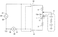
次に、入力状態検出装置において、静電容量型センサユニット10以外の構成について図1を参照して説明する。入力状態検出装置は、図1に示すように、静電容量型センサユニット10の他に、定電圧電源装置20、電流計30、電極側切替部40、状態切替部50、制御部60、入力検出部70を備える。(3. Description of Other Configurations in Input State Detection Device)
Next, the configuration of the input state detection device other than the
定電圧電源装置20は、印加端子21を静電容量型センサ1側に接続し、静電容量型センサ1に対して周期的な電圧(交流電圧、矩形波電圧など)を印加する電源である。定電圧電源装置20の接地端子22は、グランド電位に接続される。
The constant voltage
電流計30(検出器)は、静電容量型センサ1に直列接続される。特に、電流計30の検出端子31が、静電容量型センサ1側に接続され、電流計30の接地端子32がグランド電位側に接続される。すなわち、静電容量型センサ1は、定電圧電源装置20の印加端子21と電流計30の検出端子31との間に接続される。また、電流計30の接地端子32は、定電圧電源装置20の接地端子22に接続される。電流計30は、検出端子31から流れる電流を検出する。ここで、電流計30により検出される電流は、静電容量型センサ1の静電容量および対象物である人間の指の静電容量に応じて変化する。
The ammeter 30 (detector) is connected in series to the
電極側切替部40の一端が定電圧電源装置20の印加端子21側または電流計30の検出端子31側に接続され、他端が各列の第二電極12a〜12hの一端(図1の下端)に接続されている。そして、電極側切替部40は、各スイッチ40a〜40hを備えており、各計測対象に応じて予め設定された第二電極12a〜12hの1つに接続されるスイッチが閉成(ON)し、残りのスイッチは開成(OFF)する。図1においては、ハッチングを付した静電容量型センサ1を計測対象とした場合には、第二電極12aに接続されているスイッチ40aが閉成し、残りのスイッチ40b〜40hは開成している。
One end of the electrode
状態切替部50は、第一スイッチ51および第二スイッチ52を備える。第一スイッチ51の一端は第一電極11に接続される。第一スイッチ51の他端は、定電圧電源装置20の印加端子21への接続と電流計30の検出端子31への接続とを選択的に切替可能である。また、第二スイッチ52の一端は、電極側切替部40を介して第二電極12a〜12hに接続される。第二スイッチ52の他端は、定電圧電源装置20の印加端子21への接続と電流計30の検出端子31への接続とを選択的に切替可能である。
The
状態切替部50の第一,第二スイッチ51,52の切替動作は、制御部60によって制御される。制御部60は、第一スイッチ51と第二スイッチ52とが連動して動作するように制御する。具体的には、第一スイッチ51が定電圧電源装置20の印加端子21側に接続されている場合には、第二スイッチ52は電流計30の検出端子31側に接続される。一方、第一スイッチ51が電流計30の検出端子31側に接続されている場合には、第二スイッチ52は定電圧電源装置20の印加端子21側に接続される。つまり、制御部60は、定電圧電源装置20の印加端子21と電流計30の検出端子31の一方が第一電極11に接続されるようにし、他方が第二電極12a〜12hの中から選択された何れかに接続されるようにする。
The switching operation of the first and
ここで、第一スイッチ51が定電圧電源装置20の印加端子21側に接続され、第二スイッチ52が電流計30の検出端子31側に接続されている状態を、第一状態と称する。一方、第一スイッチ51が電流計30の検出端子31側に接続され、第二スイッチ52が定電圧電源装置20の印加端子21側に接続されている状態を、第二状態と称する。
Here, a state in which the
つまり、状態切替部50は、定電圧電源装置20の印加端子21を第一電極11側に接続し、且つ、電流計30の検出端子31を第二電極12a〜12h側に接続する第一状態と、定電圧電源装置20の印加端子21を第二電極12a〜12h側に接続し、且つ、電流計30の検出端子31を第一電極11側に接続する第二状態とを切替可能である。
That is, the
入力検出部70は、電流計30の検出値に基づいて、対象物である人間の指が静電容量型センサユニット10における第二電極12a〜12h側の面に接触し且つ非押付状態(以下、「接触非押付状態」と称する)であるか否かを検出する。つまり、入力検出部70は、静電容量型センサユニット10に対して人間の指が非接触状態であるか、接触非押付状態であるかを検出する。また、入力検出部70は、電流計30の検出値に基づいて、対象物である人間の指が静電容量型センサユニット10に押付力を付与したことを検出する。つまり、入力検出部70は、静電容量型センサユニット10に対して人間の指が接触非押付状態であるか、それとも押付状態であるかを検出する。
Based on the detection value of the
より詳細には、入力検出部70は、第一状態における電流計30の検出値に基づいて、対象物である人間の指が非接触状態であるか、それとも接触非押付状態であるかを検出する。また、入力検出部70は、第二状態における電流計30の検出値に基づいて、対象物である人間の指が接触非押付状態であるか、それとも押付状態であるかを検出する。さらには、入力検出部70は、押付力が付与されている場合に、第二状態における電流計30の検出値に基づいて押付力の大きさを検出する。
More specifically, the
(4.入力状態検出装置の等価回路の説明)
次に、上述した入力状態検出装置の等価回路について、図3を参照して説明する。図3は、静電容量型センサユニット10の任意の静電容量型センサ1を計測対象とした場合の等価回路を示す。(4. Description of equivalent circuit of input state detection device)
Next, an equivalent circuit of the above-described input state detection device will be described with reference to FIG. FIG. 3 shows an equivalent circuit when an
図3に示すように、静電容量型センサ1が可変となり、静電容量型センサ1の第一電極11側に抵抗3が直列接続され、静電容量型センサ1の第二電極12a〜12h側に抵抗4が直列接続される。第一状態(図3のスイッチ51,52の実線で示す)では、定電圧電源装置20の印加端子21が静電容量型センサ1の第一電極11側に接続され、電流計30の検出端子31が静電容量型センサ1の第二電極12a〜12h側に直列接続される。第二状態(図3のスイッチ51,52の破線で示す)では、定電圧電源装置20の印加端子21が静電容量型センサ1の第二電極12a〜12h側に接続され、電流計30の検出端子31が静電容量型センサ1の第一電極11側に直列接続される。
As shown in FIG. 3, the
ここで、対象物である人間の指2の等価回路について説明する。図3の二点鎖線枠にて示すように、人間の指2は、例えば2200pFのキャパシタと、1〜10kΩの抵抗と、100pFのキャパシタとの直列回路により表される。つまり、人間の指2を表皮層15に接触する状態または表皮層15を押し付ける状態において、当該対象物の等価回路が、第二電極12a〜12h側に接続されることになる。
Here, an equivalent circuit of the
(5.第一状態における接触検出)
次に、第一状態において、対象物である人間の指2が表皮層15に接触した場合を考える。このときの回路は、図4に示すようになる。つまり、第一電極11側に定電圧電源装置20により周期的な電圧が印加される。一方、第二電極12a〜12hが、抵抗4を介して電流計30の検出端子31に接続される。そして、人間の指2は、第二電極12a〜12hと電流計30の検出端子31との間に接続される。つまり、人間の指2の等価回路が、静電容量型センサ1に直列接続され、且つ、電流計30および抵抗4の直列回路に対して並列接続される。(5. Contact detection in the first state)
Next, let us consider a case where the
このとき、定電圧電源装置20により供給される電流は、静電容量型センサ1を通過した後に、電流計30および抵抗4側の経路と、人間の指2の等価回路側の経路とに分岐される。従って、第二電極12a〜12hから人間の指2側へ電流が流れた瞬間において、電流計30に流れる電流は減少する。ここで、第二電極12a〜12hから人間の指2側へ電流が流れる瞬間は、指2が第二電極12a〜12hと抵抗4との間に電気的に接続されていなければならず、実質的に表皮層15に人間の指2が接触した瞬間に等しい。
At this time, the current supplied by the constant voltage
このように、第一状態において、対象物である人間の指2が表皮層15に接触した場合には、電流計30による検出値は、その直前に比べて減少する。そこで、入力検出部70は、第一状態における電流計30による検出値に基づいて、人間の指2が表皮層15に対して非接触状態であるか、それとも接触非押付状態であるかを検出する。
As described above, in the first state, when the
なお、第一状態において、人間の指2によって表皮層15が押し付けられた場合には、第一電極11と第二電極12a〜12hとの距離が短くなるため静電容量型センサ1の静電容量が大きくなる。そのため、静電容量型センサ1を流れる電流が大きくなる。その結果、電流計30を流れる電流も大きくなる。そして、第一状態における電流計30による検出値は、人間の指2が表皮層15に接触したか否かを検出するために用いるが、人間の指が押付力を付与したか否かを検出するためには用いない。
In the first state, when the
(6.第二状態における押付力付与の検出)
次に、第二状態において、対象物である人間の指2が表皮層15に対して押付力を付与した場合を考える。このときの回路は、図5に示すようになる。つまり、第二電極12a〜12h側に定電圧電源装置20により周期的な定電圧が印加される。一方、第一電極11が、抵抗3を介して電流計30の検出端子31に接続される。そして、人間の指2は、静電容量型センサ1と定電圧電源装置20の印加端子21との間に接続される。つまり、人間の指2の等価回路が、静電容量型センサ1、電流計30および抵抗3の直列回路に対して並列接続される。(6. Detection of pressing force application in the second state)
Next, let us consider a case where the
このとき、定電圧電源装置20により供給される電流は、静電容量型センサ1、抵抗3および電流計30側の経路と、人間の指2の等価回路側の経路とに分岐される。しかし、定電圧電源装置20であることに加えて、静電容量型センサ1と人間の指2とは並列接続されるため、人間の指2の等価回路側の経路に流れる電流の分、静電容量型センサ1側の経路に流れる電流は元の大きさと同程度となるように、定電圧電源装置20が電流を供給することになる。従って、第二状態において、人間の指2が表皮層15に接触しているとしても、静電容量型センサ1側の経路に流れる電流にはほとんど影響を及ぼさない。
At this time, the current supplied by the constant voltage
一方、人間の指2による押付力によって、第一電極11と第二電極12a〜12hとの距離が短くなるため静電容量型センサ1の静電容量が変化する。具体的には、押付力が大きくなるほど、静電容量が大きくなるように変化する。つまり、静電容量型センサ1の静電容量が増加すると、静電容量型センサ1、抵抗3および電流計30側の経路に流れる電流は増加する。つまり、第二状態において押付力が大きいほど、電流計30の検出値は大きくなる。
On the other hand, since the distance between the
このように、第二状態において、対象物である人間の指2が表皮層15に押付力を付与した場合には、電流計30による検出値は、押付力の大きさに応じて変化する。そこで、入力検出部70は、第二状態における電流計30による検出値に基づいて、人間の指2が表皮層15に対して押付力を付与したか否かを検出する。つまり、入力検出部70は、第二状態において人間の指が表皮層15に対して接触非押付状態であるか、それとも押付状態であるかを検出する。さらに、入力検出部70は、表皮層15に対して付与した押付力の大きさを検出する。
Thus, in the second state, when the
なお、第二状態において、人間の指2が表皮層15に接触しただけで押付力を付与していない場合には、静電容量型センサ1側に流れる電流はほとんど変化しない。従って、第二状態における電流計30による検出値は、人間の指2が表皮層15に対して押付力を付与したか否かを検出するために用いるが、接触したか否かを検出するためには用いない。
In the second state, when the
(7.制御部による動作)
次に、制御部60により状態切替部50の第一,第二スイッチ51,52の切替タイミングについて、図6を参照して説明する。(7. Operation by control unit)
Next, the switching timing of the first and
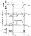
図6(a)に、人間の指2の先端位置を示す。人間の指2が、静電容量型センサユニット10の表皮層15に近づき(時刻T1より前)、表皮層15に接触した後(時刻T1−T2)に表皮層15を押付け(時刻T2ーT3)、その後に表皮層15に対して非接触状態(時刻T4より後)となる場合とする。このとき、第一状態において、電流計30に流れる電流は図6(b)に示す挙動を示し、第二状態において、電流計30に流れる電流は図6(c)に示す挙動を示す。
FIG. 6A shows the tip position of the
ただし、第一状態と第二状態とは切り替えられるため、図6(b)は、仮に第一状態が継続された場合に電流計30に流れる電流である。図6(c)も同様に、仮に第二状態が継続された場合に電流計30に流れる電流である。従って、図6(b)(c)は、実際に電流計30によって検出される電流ではない。
However, since the first state and the second state are switched, FIG. 6B shows the current flowing through the
第一状態における電流計30の検出値は、図6(b)に示すように、人間の指2が表皮層15に対して非接触状態から接触した瞬間に減少し、接触非押付状態から押付力を付与することによって僅かに増加し、押付状態から接触非押付状態になった瞬間に僅かに減少し、接触非押付状態から非接触状態になることで増加して再び初期値に戻る。
The detection value of the
一方、第二状態における電流計30の検出値は、図6(c)に示すように、人間の指2が表皮層15に対して非接触状態および接触非押付状態においては、ほとんど変化しない。そこで、このときの電流計30の検出値が基準値として規定される。続いて、表皮層15に対して接触非押付状態から押付力が付与されると、押付力の大きさが増加するに従って、電流計30による検出値が増加する。ここで、電流計30による検出値と基準値に対する差とが、押付力の大きさに対応する。続いて、押付状態から押付力がゼロになり非接触になると、電流計30による検出値は初期値(基準値に相当)に戻る。
On the other hand, as shown in FIG. 6C, the detection value of the
上記のように、人間の指2の先端位置、第一状態における電流計30の検出値、および、第二状態における電流計30の検出値は変化する。このとき、制御部60により、状態切替部50のスイッチ51,52の切替タイミングは、以下のように行われる。
As described above, the tip position of the
スイッチ51,52の切替タイミングは、図6(d)に示すように行う。つまり、制御部60は、状態切替部50のスイッチ51,52を第一状態と第二状態とに周期的に切り替える。周期は、人間の指2が表皮層15に接触してから非接触となるまでの平均的な時間に比べて十分に短い時間に設定される。
The switching timing of the
このとき、入力検出部70は、第一状態において対象物である人間の指2が表皮層15に対して非接触状態であるか接触非押付状態であるかの検出と、第二状態において接触非押付状態であるか押付状態であるかの検出とを、周期的に行う。もちろん、第二状態においては、入力検出部70は、押付力の大きさも検出する。
At this time, the
具体的には、入力検出部70は、第一状態のときに、電流計30による検出値が第一閾値Th1を下回ったことを判定することで、人間の指2が表皮層15に対して非接触状態から接触非押付状態に変化したことを検出する。図6(d)では、時刻T1より僅かに後の第一状態のときに、入力検出部70は、人間の指2が表皮層15に接触したことを検出する。
Specifically, the
そして、入力検出部70は、第二状態のときに、電流計30による検出値が第二閾値Th2を上回ったことを判定することで、人間の指2が表皮層15に対して接触非押付状態から押付状態に変化したことを検出する。図6(d)では、時刻T2に第二状態であるため、時刻T2の時点で、入力検出部70は、人間の指2が表皮層15に押付力を付与したことを検出する。さらに、入力検出部70は、第二状態において、押付力の大きさも検出する。
The
さらに、入力検出部70は、第二状態のときに、電流計30による検出値が第二閾値Th2を下回ったことを判定することで、人間の指2が表皮層15に対して押付状態から接触非押付状態に変化したことを検出する。図6(d)では、時刻T3付近で、入力検出部70は、人間の指2が表皮層15に対する押付力を解除したことを検出する。
Furthermore, the
また、入力検出部70は、第一状態のときに、電流計30による検出値が第一閾値Th1を上回ったことを判定することで、人間の指2が表皮層15に対して接触非押付状態から非接触状態に変化したことを検出する。図6(d)では、時刻T4より僅かに後の第一状態のときに、入力検出部70は、人間の指2が表皮層15から非接触状態になったことを検出する。
Further, the
つまり、人間の指2の接触の検出と指2が押付力を付与したことの検出とを交互に行うため、人間の指2の押付状態を早期に検出できる。また、人間の指2が第二電極12a〜12hへの押付状態から第二電極12a〜12hから離間したことを早期に検出できる。
That is, since the detection of the contact of the
<第二実施形態>
第二実施形態の入力状態検出装置について、図7および図8を参照して説明する。本実施形態の入力状態検出装置は、第一実施形態の入力状態検出装置に対して、制御部160および入力検出部170が相違する。他の構成は、同一符号を付して、説明を省略する。<Second embodiment>
The input state detection device of the second embodiment will be described with reference to FIGS. The input state detection device of this embodiment is different from the input state detection device of the first embodiment in a
制御部160は、図7に示すように、入力検出部170による判定に基づいて、非接触状態、接触非押付状態および押付状態の変化を取得する。そして、制御部160は、入力検出部170から取得する情報に基づいて、状態切替部50の第一,第二スイッチ51,52の切替動作を制御する。状態切替部50は、制御部160により、以下の第一モード、第二モードおよび第三モードの何れかとされる。第一モードは、状態切替部50に第一状態を継続させるモードである。第二モードは、状態切替部50に第二状態を継続させるモードである。第三モードは、状態切替部50に第一状態と第二状態とを周期的に交互に切り替えさせるモードである。
As illustrated in FIG. 7, the
制御部160による動作および入力検出部170による各状態の検出について、図8を参照して説明する。ここで、本実施形態における人間の指2の先端位置(図8(a))、第一状態における電流計30の検出値(図8(b))および第二状態における電流計30の検出値(図8(c))は、第一実施形態とほぼ同様の挙動を示す。従って、図8において、時刻T1〜T4は、第一実施形態の図6におけるT1〜T4と同様の意味である。
The operation by the
ただし、図8のT2〜T3に示すように、人間の指2による表皮層15への押付力が大きいため、人間の指2の先端位置、第一状態における電流計30の検出値および第二状態における電流計30の検出値が、第一実施形態に比べて大きく変位している。
However, as indicated by T2 to T3 in FIG. 8, since the pressing force of the
ここで、図8(b)に示すように、接触非押付状態のときの第一状態における電流計30の検出値(T1〜T2の最小値)と、押付状態のときの第一状態における電流計30の検出値(T2〜T3の最大値)との差は、ΔA1とする。また、図8(c)に示すように、接触非押付状態のときの第一状態における電流計30の検出値(T1〜T2の最小値)と、第一閾値Th1との差は、ΔA2とする。
Here, as shown in FIG. 8 (b), the detected value (minimum value of T1 to T2) of the
また、図8(b)に示すように、接触非押付状態のときの第二状態における電流計30の検出値(T1〜T2の最小値)と、押付状態のときの第二状態における電流計30の検出値(T2〜T3の最大値)との差は、ΔB1とする。また、図8(c)に示すように、接触非押付状態のときの第二状態における電流計30の検出値(T1〜T2の最小値)と、第二閾値Th2との差は、ΔB2とする。
Further, as shown in FIG. 8B, the detected value (minimum value of T1 to T2) of the
第一閾値Th1および第二閾値Th2は、式(1)の関係を満たすように設定される。つまり、ΔA1に対するΔA2の比が、ΔB1に対するΔB2の比より大きくなるように、第一閾値Th1および第二閾値Th2が設定される。 The first threshold Th1 and the second threshold Th2 are set so as to satisfy the relationship of Expression (1). That is, the first threshold Th1 and the second threshold Th2 are set so that the ratio of ΔA2 to ΔA1 is larger than the ratio of ΔB2 to ΔB1.

従って、接触非押付状態から押付状態へ変化するときに、第二状態における電流計30の検出値が第二閾値Th2を上回る時刻が、第一状態における電流計30の検出値が第一閾値Th1を上回る時刻よりも先となる。ここで、上記の関係が満たされるようにするために、簡易的には、第一閾値Th1および第二閾値Th2は以下のように設定される。すなわち、接触非押付状態のときの第一状態における電流計30の検出値と第一閾値Th1との差ΔA2が、接触非押付状態のときの第二状態における電流計30の検出値と第二閾値Th2との差ΔB2より大きくなるように、第一閾値Th1および第二閾値Th2が設定される。
Accordingly, when the detection value of the
図8(d)の時刻T1より前に示すように、制御部160は、初期状態として、すなわち入力検出部170にて非接触状態であると判定される場合には、状態切替部50を第一モードとする。ここで、入力検出部170は、第一モードのときに、第一状態における電流計30の検出値が第一閾値Th1を下回ることで、非接触状態から接触非押付状態に変化すると判定する。従って、図8(b)から分かるように、入力検出部170は、時刻T1のときに非接触状態から接触非押付状態に変化したと判定する。
As shown before time T1 in FIG. 8D, the
そうすると、図8(d)に示すように、制御部160は、時刻T1にて、状態切替部50を第一モードから第三モードへ切り替える。つまり、状態切替部50は、第一状態と第二状態とを交互に周期的に切り替えられる。この状態で、入力検出部170は、接触非押付状態から押付状態へ変化するか、それとも、接触非押付状態から非接触状態へ変化するかを検出する。
Then, as illustrated in FIG. 8D, the
続いて、図8(a)に示すように、時刻T2にて、人間の指2が表皮層15に対して接触非押付状態から押付状態へ変化するとする。そうすると、図8(b)(c)の時刻T2付近に示すように、第一状態における電流計30の検出値は増加すると共に、第二状態における電流計の30の検出値も増加する。
Subsequently, as shown in FIG. 8A, it is assumed that the
ただし、第一閾値Th1および第二閾値Th2は、上述したように、式(1)を満たすように設定される。そのため、接触非押付状態から押付状態へ変化するときに、第二状態における電流計30の検出値が第二閾値Th2を上回る時刻T2が、第一状態における電流計30の検出値が第一閾値Th1を上回る時刻T10よりも先となる。そして、入力検出部170は、第三モードのときに第二状態における電流計30の検出値が第二閾値Th2を上回ることで、接触非押付状態から前記押付状態に変化すると判定する。従って、図8(c)から分かるように、入力検出部170は、時刻T2のときに接触非押付状態から押付状態に変化したと判定する。
However, the first threshold Th1 and the second threshold Th2 are set so as to satisfy the expression (1) as described above. Therefore, when the change from the non-contact pressing state to the pressing state occurs, the time T2 when the detected value of the
そうすると、図8(d)に示すように、制御部160は、時刻T2にて、状態切替部50を第三モードから第二モードへ切り替える。つまり、状態切替部50は、第二状態を継続する。この状態で、入力検出部170は、押付状態から接触非押付状態に変化することを検出する。
Then, as illustrated in FIG. 8D, the
続いて、図8(a)に示すように、時刻T3にて、人間の指2が表皮層15に対して押付状態から接触非押付状態へ変化するとする。そうすると、図8(c)の時刻T3付近に示すように、第二状態における電流計30の検出値は減少する。ここで、入力検出部170は、第二モードのときに第二状態における電流計30の検出値が第二閾値Th2を下回ることで、押付状態から接触非押付状態に変化すると判定する。従って、図8(c)から分かるように、入力検出部170は、時刻T3のときに押付状態から接触非押付状態に変化したと判定する。
Subsequently, as shown in FIG. 8A, it is assumed that the
そうすると、図8(d)に示すように、制御部160は、時刻T3にて、状態切替部50を第二モードから第三モードに切り替える。つまり、状態切替部50は、再び、第一状態と第二状態とを交互に周期的に切り替えられる。
Then, as illustrated in FIG. 8D, the
続いて、図8(a)に示すように、時刻T4にて、人間の指2が表皮層15に対して接触非押付状態から非接触状態へ変化するとする。そうすると、図8(b)の時刻T4付近に示すように、第一状態における電流計30の検出値は増加するのに対して、図8(c)の時刻T4付近に示すように、第二状態における電流計30の検出値は変化しない。
Subsequently, as shown in FIG. 8A, it is assumed that the
そして、入力検出部170は、第三モードのときに第一状態における電流計30の検出値が第一閾値Th1を上回ることで、接触非押付状態から非接触状態に変化すると判定する。従って、図8(b)から分かるように、入力検出部170は、時刻T4のときに接触非押付状態から非接触状態に変化したと判定する。
And the
そうすると、図8(d)に示すように、制御部160は、時刻T4にて、状態切替部50を第三モードから第一モードに切り替える。つまり、状態切替部50は、第一状態を継続する。この状態で、入力検出部170は、再び、非接触状態から接触非押付状態に変化することを検出する。
Then, as illustrated in FIG. 8D, the
上記のように、非接触状態のときに状態切替部50が第一状態を継続する第一モードとされることで、入力検出部170は、確実に非接触状態から接触非押付状態へ変化したことを検出できる。また、押付力の大きさを検出する場合において、押付状態のときに状態切替部50が第二状態を継続する第二モードとされることで、入力検出部170は、押付力の大きさを高精度に検出できる。
As described above, when the
ただし、第一モードから第二モードへの移行、および、第二モードから第一モードへの移行の判断は容易ではない。そこで、上記によれば、第一モードと第二モードとの間での移行は、第三モードを介することとする。第三モードは、第一状態と第二状態とを周期的に交互に切り替えるモードである。つまり、第三モードのときには、状態切替部50は、第一状態を継続する第一モードへ移行することもスムースとなり、第二状態を継続する第二モードへ移行することもスムースとなる。
However, determination of the transition from the first mode to the second mode and the transition from the second mode to the first mode is not easy. Therefore, according to the above, the transition between the first mode and the second mode is made through the third mode. The third mode is a mode in which the first state and the second state are alternately switched periodically. That is, in the third mode, the
さらに、入力検出部170は、各モードにおいて第一閾値Th1または第二閾値Th2を用いることで、人間の指2による状態の変化を確実に判定できる。従って、制御部160は、各モードの切り替えを適切に行うことができる。さらに、上記のように第一閾値Th1および第二閾値Th2が設定される。これにより、制御部160は、接触非押付状態のときに、非接触状態に変化したのか、それとも、押付状態に変化したのかを確実に判定できる。その結果、制御部160は、さらに、第三モードのときに、第一モードへ切り替えるのか、それとも、第二モードへ切り替えるのかを、確実に判定できる。
Furthermore, the
<第三実施形態>
第三実施形態の入力状態検出装置における制御部160の動作について、図9を参照して説明する。本実施形態の入力状態検出装置は、第二実施形態の入力状態検出装置と実質的に同様の構成となる。<Third embodiment>
The operation of the
ここで、制御部160は、入力検出部170から取得する情報に基づいて、状態切替部50の第一,第二スイッチ51,52の切替動作を制御する。ただし、状態切替部50は、制御部160により、第一状態を継続する第一モードと、第二状態を継続する第二モードの何れかとされる。また、本実施形態における人間の指2の先端位置、第一状態における電流計30の検出値および第二状態における電流計30の検出値は、第一実施形態における各挙動を示す図6の(a)〜(c)と同一の挙動であるとする。
Here, the
制御部160による動作は、図9を参照して説明する。図9の時刻T1より前に示すように、制御部160は、初期状態として、すなわち入力検出部170にて非接触状態であると判定される場合には、状態切替部50を第一モードとする。ここで、入力検出部170は、第一モードのときに、第一状態における電流計30の検出値が第一閾値Th1を下回ることで、非接触状態から接触非押付状態に変化すると判定する。
The operation by the
図9の時刻T1のときに、入力検出部170は、人間の指2が表皮層15に対して非接触状態から接触非押付状態に変化したとことを検出する。具体的には、入力検出部170は、第一状態における電流計30による検出値が第一閾値Th1を下回ったことを判定することで、人間の指2が表皮層15に接触したことを検出する。
At time T <b> 1 in FIG. 9, the
そして、制御部160は、人間の指2が表皮層15に接触したと判定したタイミングで、状態切替部50のスイッチ51,52を第一モードから第二モードに切り替える。この状態で、入力検出部170は、人間の指2が表皮層15に対して接触非押付状態から押付状態に変化したことを検出すると共に、押付状態において押付力の大きさを検出する。具体的には、入力検出部170は、第二状態における電流計30による検出値が第二閾値Th2を上回ったか否かを判定することで、人間の指2が表皮層15に押付力を付与したことを検出する。図9では、時刻T2のときに、入力検出部170は、人間の指2が表皮層15に押付力を付与したことを検出する。
The
さらに続いて、入力検出部170は、人間の指2により押付力が減少したとき、第二状態における電流計30による検出値が第二閾値Th2を下回ったか否かを判定する。入力検出部170は、検出値が第二閾値Th2を下回ったことを判定することで、人間の指2による表皮層15に対する押付力が実質的になくなり、単なる表皮層15に接触している状態になったと判定する。つまり、入力検出部170は、時刻T3のときに、押付状態から接触非押付状態に変化したことを検出する。このタイミングで、制御部160は、状態切替部50のスイッチ51,52を第二モードから第一モードに切り替える。図9では、時刻T3のときに、入力検出部170は、人間の指2が表皮層15に対する押付力を解除したことを検出する。
Subsequently, when the pressing force is reduced by the
そして、入力検出部170は、第一モードに切り替えられた後に、電流計30による検出値が第一閾値Th1を上回ったことを判定することで、人間の指2が表皮層15に対して接触非押付状態から非接触状態に変化したことを検出する。図9では、時刻T4のときに、入力検出部170は、人間の指2が表皮層15から非接触状態になったことを検出する。
Then, after the
そして、再び、人間の指2によって表皮層15に対して非接触状態から接触非押付状態に変化するときまで、制御部160は、状態切替部50を第一モードとする。これにより、確実に、人間の指2の表皮層15への接触および押付状態を検出できる。このとき、状態切替部50による切替動作の回数を少なくすることができ、消費エネルギーを低減できる。
Then, the
<第四実施形態>
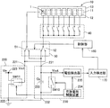
第一〜第三実施形態においては、複数の静電容量型センサ1が一列に並んで構成される。図10に示すように、入力状態検出装置は、複数の静電容量型センサユニット10,10と、それぞれに対応する複数の定電圧電源装置20,20、複数の電流計30,30、複数の電極側切替部40,40、複数の状態切替部50,50と、共通の制御部60、共通の入力検出部70を備える。<Fourth embodiment>
In the first to third embodiments, a plurality of
検出範囲5は、複数の静電容量型センサユニット10,10を含む範囲となる。従って、入力状態検出装置は、広範囲に亘って、人間の指2が表皮層15に対して、非接触状態、接触非押付状態および押付状態の検出が可能となる。
The
<第五実施形態>
上記実施形態においては、入力状態検出装置は、電流計30を用いて検出端子31に流れる電流を検出することで、非接触状態、接触非押付状態および押付状態を検出した。この他に、入力状態検出装置は、以下の検出器230を用いて、検出端子231における電位を検出することで、入力状態を検出することができる。<Fifth embodiment>
In the above embodiment, the input state detection device detects the non-contact state, the contact non-pressing state, and the pressing state by detecting the current flowing through the
(入力状態検出装置の構成)
検出器230を用いる入力状態検出装置について、図11を参照して説明する。入力状態検出装置は、静電容量型センサユニット10、定電圧電源装置220、検出器230、電極側切替部40、状態切替部50、制御部160、入力検出部170を備える。ここで、本実施形態における定電圧電源装置220および検出器230以外の構成は、第一実施形態または第二実施形態において同一符号を付す構成と同様である。(Configuration of input state detection device)
An input state detection apparatus using the
定電圧電源装置220は、定電圧電源223と、入力用スイッチング素子SW11とを備える。定電圧電源223は、一定の電圧である入力電圧Vinを印加可能な電源である。入力用スイッチング素子SW11の一端側である印加端子221は、静電容量型センサ1側に接続される。入力用スイッチング素子SW11の他端側は、定電圧電源223とグランド電位側の接地端子222との一方に切り替え可能に接続される。つまり、入力用スイッチング素子SW11が定電圧電源223側に接続されている場合には、静電容量型センサ1に入力電圧Vinが印加される状態となる。一方、入力用スイッチング素子SW11がグランド電位側に接続されている場合には、静電容量型センサ1には入力電圧Vinが印加されない状態となる。
The constant voltage
検出器230は、ブリッジ用キャパシタ233、充放電用スイッチング素子SW10、充放電用制御装置234、電位検出器235を備える。ブリッジ用キャパシタ233は、静電容量型センサ1の他方(定電圧電源装置220とは異なる側)に対して直列接続され、静電容量型センサ1とグランド電位との間に接続される。つまり、静電容量型センサ1とブリッジ用キャパシタ233とが、ブリッジ回路を構成する。ここで、ブリッジ用キャパシタ233の静電容量は、Cbである。
The
充放電用スイッチング素子SW10は、静電容量型センサ1の他方に対して直列接続されると共に、ブリッジ用キャパシタ233に対して並列接続される。さらに、充放電用スイッチング素子SW10は、閉状態時に静電容量型センサ1の他方の電荷をグランド電位に放電する。
The charging / discharging switching element SW10 is connected in series to the other of the
充放電用制御装置234は、以下に示す放電工程と充電工程とを交互に実行する。すなわち、充放電用制御装置234は、入力用スイッチング素子SW11をグランド電位側に接続した状態にし、且つ、充放電用スイッチング素子SW10を閉状態にすることで、静電容量型センサ1の電荷をグランド電位に放電する(放電工程)。ここで、入力用スイッチング素子SW11をグランド電位側に接続した状態とは、静電容量型センサ1に対して入力電圧Vinを印加していない状態に相当する。上記放電工程により、静電容量型センサ1の電荷を基準状態としてのグランド電位に設定することで、キャリブレーションを行うことができる。
The charging / discharging
また、充放電用制御装置234は、上記放電工程の後に、入力用スイッチング素子SW11を定電圧電源223側に接続した状態にし、且つ、充放電用スイッチング素子SW10を開状態にすることで、静電容量型センサ1に充電する(充電工程)。ここで、入力用スイッチング素子SW11を定電圧電源223側に接続した状態とは、静電容量型センサ1に対して入力電圧Vinを印加する状態に相当する。
In addition, the charging / discharging
電位検出器235は、充放電用制御装置234が充電工程を実行する場合において、静電容量型センサ1とブリッジ用キャパシタ233との間の電位Vout(以下、「出力電位」とも称する)を検出する。なお、出力電位Voutは、静電容量型センサ1の他方の電位に相当する。
The
(非接触状態のときの等価回路)
人間の指2が表皮層15に対して非接触状態のときの入力状態検出装置の等価回路は、図12に示すような回路となる。入力用スイッチング素子SW11が定電圧電源223側に接続される状態において、出力電位Vout0は、静電容量型センサ1の静電容量Cn0、ブリッジ用キャパシタ233の静電容量Cb、入力電圧Vinによって、式(2)のように表される。(Equivalent circuit in non-contact state)
An equivalent circuit of the input state detection device when the
ここで、ブリッジ用キャパシタ233の静電容量Cbおよび入力電圧Vinは、既知である。従って、式(2)により、電位検出器235により検出される出力電位Vout0は、静電容量型センサ1の静電容量に相当する値となる。
Here, the capacitance Cb and the input voltage Vin of the
(充放電用制御装置の動作)
次に、人間の指2が表皮層15に対して非接触状態のときにおいて、充放電用制御装置234が実行する充放電用スイッチング素子SW10の開閉のタイミングと、静電容量型センサ1の一方の電位Vin1および出力電位Voutの関係について、図13を参照して説明する。T11〜T12において、充放電用スイッチング素子SW10がON(閉状態)とされる。また、入力用スイッチング素子SW11がグランド電位側に接続される。従って、静電容量型センサ1の一方の電位Vin1が、グランド電位となる。(Operation of charge / discharge controller)
Next, when the
上記動作によって、静電容量型センサ1の電荷が、充放電用スイッチング素子SW10を介して、放電される。その結果、静電容量型センサ1とブリッジ用キャパシタ233との間の出力電位Voutが基準状態としてのグランド電位となる。つまり、上記動作前においては、出力電位Voutが不定であったが、上記動作によって、出力電位Voutがグランド電位に設定される。
With the above operation, the electric charge of the
続いて、T12〜T14において、充放電用スイッチング素子SW10がOFF(開状態)とされ、入力用スイッチング素子SW11が定電圧電源223側に接続される。従って、静電容量型センサ1の一方の電位Vin1が、入力電圧Vinとなる。上記動作によって、静電容量型センサ1に電荷が充電される。充電に要する時間を経過した後に(図2のT13〜T14)において、電位検出器235が、出力電位Voutを検出する。電位検出器235が検出する出力電位Voutが、検出対象である出力電位Vout0である。
Subsequently, in T12 to T14, the charging / discharging switching element SW10 is turned off (opened), and the input switching element SW11 is connected to the constant
続いて、T14〜T15において、充放電用スイッチング素子SW10はON(閉状態)とされ、入力用スイッチング素子SW11がグランド電位側に接続される。この動作によって、静電容量型センサ1の一方の電位Vin1はグランド電位となり、静電容量型センサ1の電荷が放電される。すなわち、上記出力電位Voutがグランド電位になる。続いて、T15〜T19は、上述したT11〜T15と同様の動作を繰り返す。
Subsequently, in T14 to T15, the charging / discharging switching element SW10 is turned on (closed state), and the input switching element SW11 is connected to the ground potential side. By this operation, one potential Vin1 of the
上記のとおり、ブリッジ用キャパシタ233が静電容量型センサ1に対して直列接続されており、電位検出器235が、静電容量型センサ1の他方の電位、すなわち静電容量型センサ1とブリッジ用キャパシタ233との間の出力電位Voutを検出する。ここで、単なる2つのキャパシタの中間電位は不定であるため、当該中間電位を用いて検出された静電容量は高精度ではない。
As described above, the
しかし、上記の通り、充放電用スイッチング素子SW10を閉状態にすることで、静電容量型センサ1の電荷が放電される。すなわち、上記中間電位としての出力電位Voutが基準状態としてのグランド電位になる。つまり、充放電用スイッチング素子SW10を閉状態にすることによって、出力電位Voutのキャリブレーションが行われる。
However, as described above, the charge of the
そして、電位検出器235は、放電された後に、充放電用スイッチング素子SW10を開状態にし、且つ、静電容量型センサ1の一方に入力電圧Vinを印加した状態にされた時に、静電容量型センサ1の他方の電位を検出する。つまり、電位検出器235が検出する電位は、静電容量型センサ1の静電容量Cn0に応じた電位となる。
Then, the
(接触非押付状態および押付状態の出力電位)
第一状態において、人間の指2が表皮層15に対して接触非押付状態のときの入力状態検出装置の等価回路は、図14に示すような回路となる。ここで、便宜上、人間の指2の静電容量をCyとする。入力用スイッチング素子SW11が定電圧電源223側に接続される状態において、出力電位Vout1は、静電容量型センサ1の静電容量Cn0、ブリッジ用キャパシタ233の静電容量Cb、入力電圧Vin、人間の指2の静電容量Cyによって、式(3)のように表される。ここで、接触非押付状態においては、静電容量型センサ1の静電容量Cn0は、実質上、一定値である。(Output potential in non-contact state and pressing state)
In the first state, an equivalent circuit of the input state detection device when the
式(3)と式(2)とを比較すると、人間の指2の静電容量Cyの影響により、接触非押付状態の出力電位Vout1は、非接触状態の出力電位Vout0より小さくなる。つまり、出力電位Vout0,Vout1は、第一〜第三実施形態にて示したように、電流計30による検出値と同様の挙動となる。
Comparing Expression (3) and Expression (2), the output potential Vout1 in the non-contact state is smaller than the output potential Vout0 in the non-contact state due to the influence of the electrostatic capacity Cy of the
また、第二状態において、人間の指2が表皮層15に対して押付状態のときの入力状態検出装置の等価回路は、図15に示すような回路となる。入力用スイッチング素子SW11が定電圧電源223側に接続される状態において、出力電位Vout2は、静電容量型センサ1の静電容量Cn1、ブリッジ用キャパシタ233の静電容量Cb、入力電圧Vin、人間の指2の静電容量Cyによって、式(4)のように表される。ここで、押付状態においては、静電容量型センサ1の静電容量Cn1は、押付力に応じて変化する。
In the second state, an equivalent circuit of the input state detection device when the
ここで、押付状態における静電容量Cn1は、接触非押付状態における静電容量Cn0より大きい。従って、式(4)と式(3)とを比較すると、静電容量型センサ1の静電容量Cn1の変化により、押付状態の出力電位Vout2は、接触非押付状態の出力電位Vout1より大きくなる。つまり、出力電位Vout1,Vout2は、第一〜第三実施形態にて示したように、電流計30による検出値と同様の挙動となる。以上より、電流計30を検出器230に代えた場合であっても、人間の指2による入力状態が確実に検出される。
Here, the capacitance Cn1 in the pressed state is larger than the capacitance Cn0 in the non-pressed state. Therefore, when the formula (4) is compared with the formula (3), the output potential Vout2 in the pressed state becomes larger than the output potential Vout1 in the non-pressed state due to the change in the capacitance Cn1 of the
(その他)
上記において、入力状態検出装置は、常に、第一状態による検出と第二状態の検出の何れかを行うこととした。つまり、入力状態検出装置は、第一状態と第二状態の何れかによる検出を連続的に行った。この他に、入力状態検出装置は、第一状態と第二状態の何れかによる検出を所定の周期で断続的に行ってもよい。このようにすることで、状態切替部50による切替動作の回数がさらに少なくなり、より消費エネルギーが低減する。(Other)
In the above description, the input state detection device always performs detection of the first state or detection of the second state. That is, the input state detection device continuously performs detection in either the first state or the second state. In addition, the input state detection device may intermittently perform detection in either the first state or the second state at a predetermined cycle. By doing in this way, the frequency | count of the switching operation | movement by the
また、上述したように、静電容量型センサユニット10は、第一電極11および複数の第二電極12a〜12hを備えることにより、8個の静電容量型センサ1を構成している。従って、入力検出部70は、対象物である人間の指2が、複数箇所の静電容量型センサ1のどの位置に存在するか、さらには表皮層15に接触または押付力の付与がされているかを検出する。この他に、静電容量型センサユニット10が、1個の静電容量型センサ1を構成するようにしてもよい。この場合、静電容量型センサユニット10は、1個の第一電極と1個の第二電極を備えることになる。このとき、電極側切替部40は不要となる。
Further, as described above, the
1:静電容量型センサ、 2:人間の指(対象物)、 3,4:抵抗、 10:静電容量型センサユニット、 11:第一電極、 12a−12h:第二電極、 13:誘電層、 14:基材、 15:表皮層、 20,220:定電圧電源装置、 21,221:印加端子、 22,222:接地端子、 30:電流計(検出器)、 31,231:検出端子、 32,232:接地端子、 40:電極側切替部、 50:状態切替部、 51:第一スイッチ、 52:第二スイッチ、 60,160,260:制御部、 70,170,270:入力検出部、 223:定電圧電源、 230:検出器、 233:ブリッジ用キャパシタ、 234:充放電用制御装置、 235:電位検出器、 SW10:充放電用スイッチング素子、 SW11:入力用スイッチング素子、 Th1:第一閾値、 Th2:第二閾値、 Vin:入力電圧、 Vout、Vout1,Vout2,Vout3:出力電位 1: Capacitance sensor, 2: Human finger (object), 3, 4: Resistance, 10: Capacitance sensor unit, 11: First electrode, 12a-12h: Second electrode, 13: Dielectric Layer, 14: base material, 15: skin layer, 20, 220: constant voltage power supply, 21, 221: application terminal, 22, 222: ground terminal, 30: ammeter (detector), 31, 231: detection terminal 32: 232: ground terminal, 40: electrode switching unit, 50: state switching unit, 51: first switch, 52: second switch, 60, 160, 260: control unit, 70, 170, 270: input detection 223: constant voltage power source, 230: detector, 233: capacitor for bridge, 234: controller for charging / discharging, 235: potential detector, SW10: switching element for charging / discharging, SW11: for input Switching elements, Th1: first threshold value, Th2: the second threshold value, Vin: Input voltage, Vout, Vout1, Vout2, Vout3: output potential
Claims (10)
印加端子を前記静電容量型センサ側に接続し、前記静電容量型センサに対して所定電圧を印加する定電圧電源装置と、
前記静電容量型センサに直列接続され、検出端子を前記静電容量型センサ側に接続し、前記静電容量型センサの静電容量および前記対象物の静電容量に応じて変化する前記検出端子における電位または前記検出端子から流れる電流を検出する検出器と、
前記定電圧電源装置の印加端子を前記第一電極側に接続し、かつ、前記検出器の検出端子を前記第二電極側に接続する第一状態と、前記定電圧電源装置の印加端子を前記第二電極側に接続し、かつ、前記検出器の検出端子を前記第一電極側に接続する第二状態とを切替可能な状態切替部と、
前記第一状態における前記検出器の検出値に基づいて前記対象物が前記静電容量型センサにおける前記第二電極側の面に対して非接触状態であるか接触非押付状態であるかを検出すると共に、前記第二状態における前記検出器の検出値に基づいて前記対象物が前記第二電極に対して接触非押付状態であるか押付状態であるかを検出する入力検出部と、
を備え、
前記検出器は、
前記検出器の前記検出端子とグランド電位との間に接続されるブリッジ用キャパシタと、
前記ブリッジ用キャパシタに対して並列接続され、閉状態時に前記検出端子の電荷をグランド電位に放電する充放電用スイッチング素子と、
前記定電圧電源装置が前記静電容量型センサに対して前記所定電圧を印加していない状態において、前記検出端子の電荷をグランド電位に放電する工程と、前記放電する工程の後に、前記充放電用スイッチング素子を開状態にし且つ前記定電圧電源装置により前記所定電圧が印加される状態にすることで、前記静電容量型センサに充電する工程とを実行する充放電用制御装置と、
前記充放電用制御装置による前記充電する工程において、前記静電容量型センサの静電容量および前記対象物の静電容量に応じた値として、前記検出端子の電位を検出する電位検出器と、
を備える、入力状態検出装置。 The first electrode attached to the base material, the second electrode located on the side of the conductive object to be contacted, the second electrode by the object and disposed between the first electrode and the second electrode A capacitive sensor comprising a dielectric layer compressed by a pressing force against the electrode;
A constant voltage power supply device that connects an application terminal to the capacitive sensor and applies a predetermined voltage to the capacitive sensor;
The detection is connected in series to the capacitance type sensor, the detection terminal is connected to the capacitance type sensor side, and changes according to the capacitance of the capacitance type sensor and the capacitance of the object. A detector for detecting a potential at a terminal or a current flowing from the detection terminal;
A first state in which an application terminal of the constant voltage power supply device is connected to the first electrode side, and a detection terminal of the detector is connected to the second electrode side; and an application terminal of the constant voltage power supply device is A state switching unit connected to the second electrode side and capable of switching between a second state of connecting the detection terminal of the detector to the first electrode side;
Based on the detection value of the detector in the first state, it is detected whether the object is in a non-contact state or a contact non-pressing state with respect to the surface on the second electrode side in the capacitance type sensor. And an input detection unit that detects whether the object is in a non-contacting state or a pressing state with respect to the second electrode based on a detection value of the detector in the second state;
Equipped with a,
The detector is
A bridge capacitor connected between the detection terminal of the detector and a ground potential;
A charge / discharge switching element that is connected in parallel to the bridge capacitor and discharges the charge of the detection terminal to a ground potential in a closed state;
In a state where the constant voltage power supply device does not apply the predetermined voltage to the capacitance type sensor, the charge / discharge is performed after the step of discharging the charge of the detection terminal to a ground potential and the step of discharging. A charging / discharging control device that performs a step of charging the capacitance type sensor by opening the switching element for use and applying the predetermined voltage by the constant voltage power supply device;
In the charging step by the charge / discharge control device, a potential detector that detects a potential of the detection terminal as a value according to a capacitance of the capacitance sensor and a capacitance of the object;
Ru provided with an input state detecting device.
前記制御部は、前記状態切替部を前記第一状態と前記第二状態とに周期的に切り替え、
前記入力検出部は、前記非接触状態であるか前記接触非押付状態であるかの検出と、前記接触非押付状態であるか前記押付状態であるかの検出とを周期的に行う、請求項1または2に記載の入力状態検出装置。 The input state detection device includes a control unit that controls the state of the state switching unit,
The control unit periodically switches the state switching unit between the first state and the second state,
The input detection unit periodically performs detection of the non-contact state or the contact non-pressing state and detection of the contact non-pressing state or the pressing state. The input state detection device according to 1 or 2 .
前記入力状態検出装置は、前記状態切替部のモードを制御する制御部を備え、
前記制御部は、
前記非接触状態から前記接触非押付状態に変化するときに、前記状態切替部を前記第一モードから前記第三モードに切り替え、
前記接触非押付状態から前記非接触状態に変化するときに、前記状態切替部を前記第三モードから前記第一モードに切り替え、
前記接触非押付状態から前記押付状態に変化するときに、前記状態切替部を前記第三モードから前記第二モードに切り替え、
前記押付状態から前記接触非押付状態に変化するときに、前記状態切替部を前記第二モードから前記第三モードに切り替える、
請求項1〜3の何れか一項に記載の入力状態検出装置。 The mode in which the state switching unit continues the first state is the first mode, the mode in which the state switching unit continues the second state is the second mode, and the state switching unit has the first state and the first mode. The mode that periodically switches between the two states is the third mode,
The input state detection device includes a control unit that controls a mode of the state switching unit,
The controller is
When changing from the non-contact state to the contact non-pressing state, the state switching unit is switched from the first mode to the third mode,
When changing from the contact non-pressing state to the non-contact state, the state switching unit is switched from the third mode to the first mode,
When changing from the non-contact pressing state to the pressing state, the state switching unit is switched from the third mode to the second mode,
When changing from the pressing state to the contact non-pressing state, the state switching unit is switched from the second mode to the third mode;
The input state detection apparatus as described in any one of Claims 1-3 .
前記第一モードのときに前記第一状態における前記検出器の検出値が第一閾値を下回ることで前記非接触状態から前記接触非押付状態に変化すると判定し、
前記第三モードのときに前記第一状態における前記検出器の検出値が前記第一閾値を上回ることで前記接触非押付状態から前記非接触状態に変化すると判定し、
前記第三モードのときに前記第二状態における前記検出器の検出値が第二閾値を上回ることで前記接触非押付状態から前記押付状態に変化すると判定し、
前記第二モードのときに前記第二状態における前記検出器の検出値が前記第二閾値を下回ることで前記押付状態から前記接触非押付状態に変化すると判定し、
前記制御部は、前記入力検出部による判定に基づいて、前記非接触状態、前記接触非押付状態および前記押付状態の変化を取得する、
請求項4に記載の入力状態検出装置。 The input detection unit
When the detection value of the detector in the first state during the first mode is less than a first threshold, it is determined that the non-contact state changes to the contact non-pressing state,
It is determined that the detection value of the detector in the first state during the third mode is changed from the contact non-pressing state to the non-contact state by exceeding the first threshold value,
It is determined that the detection value of the detector in the second state during the third mode is changed from the contact non-pressing state to the pressing state by exceeding a second threshold value,
It is determined that the detection value of the detector in the second state changes from the pressing state to the contact non-pressing state when the second mode is below the second threshold value,
The control unit acquires changes in the non-contact state, the contact non-pressing state, and the pressing state based on the determination by the input detection unit.
The input state detection device according to claim 4 .
前記第一閾値および前記第二閾値が設定される、
請求項5に記載の入力状態検出装置。 The difference between the detection value of the detector in the first state when the contact is not pressed and the first threshold value is the detection value of the detector in the second state when the contact is not pressed. To be larger than the difference from the second threshold,
The first threshold and the second threshold are set;
The input state detection device according to claim 5 .
前記入力状態検出装置は、前記状態切替部の状態を制御する制御部を備え、
前記制御部は、
前記非接触状態から前記接触非押付状態に変化するときに、前記状態切替部を前記第一モードから前記第二モードに切り替え、
前記押付状態から前記接触非押付状態に変化するときに、前記状態切替部を前記第二モードから前記第一モードに切り替える、
請求項1または2に記載の入力状態検出装置。 The mode for causing the state switching unit to continue the first state is a first mode, and the mode for causing the state switching unit to continue the second state is a second mode.
The input state detection device includes a control unit that controls the state of the state switching unit,
The controller is
When changing from the non-contact state to the contact non-pressing state, the state switching unit is switched from the first mode to the second mode,
When changing from the pressing state to the contact non-pressing state, the state switching unit is switched from the second mode to the first mode;
Input state detecting device according to claim 1 or 2.
前記入力検出部は、前記対象物が存在する位置を検出する、請求項1〜7の何れか一項に記載の入力状態検出装置。 By providing a plurality of at least one of the first electrode and the second electrode, a plurality of capacitance sensors are configured,
The input detection unit detects a position where the object is present, the input state detecting device according to any one of claims 1-7.
Applications Claiming Priority (3)
| Application Number | Priority Date | Filing Date | Title |
|---|---|---|---|
| JP2013157806 | 2013-07-30 | ||
| JP2013157806 | 2013-07-30 | ||
| PCT/JP2014/067440 WO2015015983A1 (en) | 2013-07-30 | 2014-06-30 | Input state detection device |
Publications (2)
| Publication Number | Publication Date |
|---|---|
| JPWO2015015983A1 JPWO2015015983A1 (en) | 2017-03-02 |
| JP6286430B2 true JP6286430B2 (en) | 2018-02-28 |
Family
ID=52431524
Family Applications (1)
| Application Number | Title | Priority Date | Filing Date |
|---|---|---|---|
| JP2015529468A Active JP6286430B2 (en) | 2013-07-30 | 2014-06-30 | Input state detection device |
Country Status (5)
| Country | Link |
|---|---|
| US (1) | US10133413B2 (en) |
| EP (1) | EP2950190B1 (en) |
| JP (1) | JP6286430B2 (en) |
| CN (1) | CN105453008B (en) |
| WO (1) | WO2015015983A1 (en) |
Families Citing this family (19)
| Publication number | Priority date | Publication date | Assignee | Title |
|---|---|---|---|---|
| US9660646B1 (en) * | 2013-03-10 | 2017-05-23 | Apple Inc. | Multiple controllers for a capacitive sensing device |
| DE112015005942T5 (en) * | 2015-01-13 | 2017-10-19 | Sumitomo Riko Company Limited | Capacitance measuring device, capacitance-type flat sensor device and capacitance-type liquid level detection device |
| JP2016167252A (en) * | 2015-03-02 | 2016-09-15 | 学校法人福岡大学 | Proximity/contact sensor and information terminal |
| SE1650548A1 (en) | 2016-04-22 | 2017-10-23 | Fingerprint Cards Ab | Fingerprint sensing system with sensing reference potential providing circuitry |
| IT201600103234A1 (en) | 2016-10-14 | 2018-04-14 | Green Seas Ventures Ldt | Constructive system relating to a capacitive voltage sensor |
| CN108334222A (en) * | 2017-01-19 | 2018-07-27 | 希迪普公司 | Touch input device |
| DE102017106207A1 (en) * | 2017-03-22 | 2018-09-27 | Fm Marketing Gmbh | grid plate |
| JP2018163807A (en) * | 2017-03-27 | 2018-10-18 | Smk株式会社 | Pressure-sensitive electrostatic switch and electrical device |
| JP6996355B2 (en) | 2018-03-06 | 2022-01-17 | 株式会社デンソー | Capacitive operation device |
| IT201800004114A1 (en) | 2018-03-30 | 2019-09-30 | Green Seas Ventures Ltd C/O Citco B V I Ltd | CONSTRUCTION SYSTEM WITH A CAPACITIVE VOLTAGE SENSOR |
| DE102018205084A1 (en) * | 2018-04-04 | 2019-10-10 | Audi Ag | Capacitive sensor component |
| EP3899557A4 (en) | 2018-12-17 | 2022-10-26 | G & W Electric Company | Electrical sensor assembly |
| BR112021011522A2 (en) | 2018-12-17 | 2021-08-31 | G & W Electric Company | SET OF ELECTRICAL SENSORS |
| JP7216963B2 (en) * | 2019-10-03 | 2023-02-02 | 本田技研工業株式会社 | CAPACITIVE DETECTION SENSOR, CAPACITIVE DETECTION SENSOR MODULE, AND STATE DETERMINATION METHOD USING CAPACITIVE DETECTION SENSOR |
| TWI744760B (en) * | 2019-12-30 | 2021-11-01 | 財團法人工業技術研究院 | Electrostatic sensing system and electrostatic sensing assembly |
| TWI768439B (en) * | 2020-08-20 | 2022-06-21 | 黃湘豪 | Non-intruder inspecting and injecting protocol device |
| JP2022108974A (en) * | 2021-01-14 | 2022-07-27 | 本田技研工業株式会社 | Capacitive sensor and measuring device |
| JP7542448B2 (en) * | 2021-01-14 | 2024-08-30 | 株式会社ジャパンディスプレイ | Pressure Sensors |
| US11755095B2 (en) * | 2021-07-19 | 2023-09-12 | Stmicroelectronics S.R.L. | Bag detection using an electrostatic charge sensor |
Family Cites Families (13)
| Publication number | Priority date | Publication date | Assignee | Title |
|---|---|---|---|---|
| BE1007462A3 (en) * | 1993-08-26 | 1995-07-04 | Philips Electronics Nv | Data processing device with touch sensor and power. |
| JP3001395B2 (en) * | 1995-04-04 | 2000-01-24 | 株式会社ワコム | Position detecting device and position detecting method |
| JP3394187B2 (en) * | 1997-08-08 | 2003-04-07 | シャープ株式会社 | Coordinate input device and display integrated type coordinate input device |
| CN104965621B (en) * | 2006-06-09 | 2018-06-12 | 苹果公司 | Touch screen LCD and its operating method |
| CN101490642A (en) * | 2006-07-18 | 2009-07-22 | Iee国际电子工程股份公司 | Input device |
| US8063886B2 (en) | 2006-07-18 | 2011-11-22 | Iee International Electronics & Engineering S.A. | Data input device |
| JP2010217967A (en) * | 2009-03-13 | 2010-09-30 | Alps Electric Co Ltd | Input device |
| KR101578075B1 (en) * | 2009-04-20 | 2015-12-17 | 삼성디스플레이 주식회사 | Method of detecting a touch and device of detecting a touch for performing the same |
| JP5396335B2 (en) * | 2009-05-28 | 2014-01-22 | 株式会社半導体エネルギー研究所 | Touch panel |
| JP2012022635A (en) * | 2010-07-16 | 2012-02-02 | Alps Electric Co Ltd | Electrostatic capacitance type proximity sensor device, and electrostatic capacitance type motion detection device using the same |
| EP2690786A1 (en) * | 2012-07-25 | 2014-01-29 | Electrolux Home Products Corporation N.V. | A control device, in particular for a domestic appliance |
| JP6248406B2 (en) * | 2013-04-09 | 2017-12-20 | 日本電産リード株式会社 | Inspection apparatus and inspection method |
| US9279841B2 (en) * | 2013-07-29 | 2016-03-08 | Tritan Technology Inc. | Integratable capacitive touch sensing circuit through charge sharing |
-
2014
- 2014-06-30 WO PCT/JP2014/067440 patent/WO2015015983A1/en active Application Filing
- 2014-06-30 CN CN201480043281.7A patent/CN105453008B/en active Active
- 2014-06-30 EP EP14831907.2A patent/EP2950190B1/en active Active
- 2014-06-30 JP JP2015529468A patent/JP6286430B2/en active Active
-
2015
- 2015-07-28 US US14/810,716 patent/US10133413B2/en active Active
Also Published As
| Publication number | Publication date |
|---|---|
| US20150346907A1 (en) | 2015-12-03 |
| CN105453008B (en) | 2018-09-07 |
| WO2015015983A1 (en) | 2015-02-05 |
| EP2950190A4 (en) | 2016-08-24 |
| CN105453008A (en) | 2016-03-30 |
| JPWO2015015983A1 (en) | 2017-03-02 |
| EP2950190A1 (en) | 2015-12-02 |
| US10133413B2 (en) | 2018-11-20 |
| EP2950190B1 (en) | 2019-05-22 |
Similar Documents
| Publication | Publication Date | Title |
|---|---|---|
| JP6286430B2 (en) | Input state detection device | |
| JP5326042B2 (en) | Capacitance type sensor device and capacitance measuring device for capacitance type sensor | |
| KR101742604B1 (en) | Capacitive voltage divider touch sensor | |
| JP4897886B2 (en) | Capacitive proximity sensor and proximity detection method | |
| WO2016113840A1 (en) | Capacitance measurement device, capacitive planar sensor device, and capacitive liquid level detection device | |
| US20090114456A1 (en) | Press on power-up detection for a touch-sensor device | |
| EP3210305A1 (en) | Analog elimination of ungrounded conductive objects in capacitive sensing | |
| EP1635147A3 (en) | Capacitance measuring apparatus and method | |
| EP3057235B1 (en) | Touch sensor | |
| TW200915161A (en) | Two-dimensional position sensor | |
| KR20150129643A (en) | Electrostatic stylus | |
| CN111208914A (en) | Touch detection circuit, input device, and electronic apparatus | |
| TWI383158B (en) | Capacitance measurement circuit and method | |
| JP7296603B2 (en) | Detection circuit and load detection device | |
| JP6183042B2 (en) | Touch sensor | |
| JP6194860B2 (en) | Touch sensor | |
| JP5721745B2 (en) | Circuit arrangement for determining the capacitance of multiple capacitive sensor elements | |
| JP5666711B2 (en) | Touch recognition method, touch key structure, and touch device | |
| US10551982B2 (en) | Instruction reception apparatus, information processing apparatus, signal processing method, and program | |
| JP6182031B2 (en) | Capacitance measurement device, capacitance-type surface sensor device, and capacitance-type liquid level detection device | |
| JP2015219703A (en) | Electrostatic detection device | |
| KR20150090940A (en) | Method for detecting pressure event using capacitive touch input device | |
| WO2024070102A1 (en) | Load detecting device and detecting circuit | |
| EP2722985A1 (en) | Method of differential measurement of voltage levels of capacitive change | |
| JP2023122376A (en) | Switching device |
Legal Events
| Date | Code | Title | Description |
|---|---|---|---|
| A621 | Written request for application examination |
Free format text: JAPANESE INTERMEDIATE CODE: A621 Effective date: 20170306 |
|
| A131 | Notification of reasons for refusal |
Free format text: JAPANESE INTERMEDIATE CODE: A131 Effective date: 20171114 |
|
| A521 | Written amendment |
Free format text: JAPANESE INTERMEDIATE CODE: A523 Effective date: 20180115 |
|
| TRDD | Decision of grant or rejection written | ||
| A01 | Written decision to grant a patent or to grant a registration (utility model) |
Free format text: JAPANESE INTERMEDIATE CODE: A01 Effective date: 20180125 |
|
| A61 | First payment of annual fees (during grant procedure) |
Free format text: JAPANESE INTERMEDIATE CODE: A61 Effective date: 20180205 |
|
| R150 | Certificate of patent or registration of utility model |
Ref document number: 6286430 Country of ref document: JP Free format text: JAPANESE INTERMEDIATE CODE: R150 |