JP6285301B2 - Control device for internal combustion engine - Google Patents
Control device for internal combustion engine Download PDFInfo
- Publication number
- JP6285301B2 JP6285301B2 JP2014141851A JP2014141851A JP6285301B2 JP 6285301 B2 JP6285301 B2 JP 6285301B2 JP 2014141851 A JP2014141851 A JP 2014141851A JP 2014141851 A JP2014141851 A JP 2014141851A JP 6285301 B2 JP6285301 B2 JP 6285301B2
- Authority
- JP
- Japan
- Prior art keywords
- piston
- combustion engine
- internal combustion
- ratio
- dead center
- Prior art date
- Legal status (The legal status is an assumption and is not a legal conclusion. Google has not performed a legal analysis and makes no representation as to the accuracy of the status listed.)
- Expired - Fee Related
Links
Images


Description
本発明は、ピストンの圧縮行程と膨張行程の相対ストローク位置をそれぞれ変化させて、機械圧縮比と機械膨張比を変化させることのできる内燃機関の制御装置に関する。 The present invention relates to a control device for an internal combustion engine capable of changing a mechanical compression ratio and a mechanical expansion ratio by changing relative stroke positions of a compression stroke and an expansion stroke of a piston, respectively.
従来の内燃機関の制御装置としては、可変圧縮比機構を備えた以下の特許文献1に記載されたものが知られている。
As a conventional control device for an internal combustion engine, a control device described in
すなわち、前記可変圧縮比機構は、複リンク式ピストン−クランク機構を用いたものであって、特許文献1の図8に示すように、左側の図は高機械圧縮比制御でのピストン圧縮上死点位置(ピストン位置やや高)で、右側の図は低機械圧縮比制御でのピストン圧縮上死点位置(ピストン位置やや低)となっている。
That is, the variable compression ratio mechanism uses a multi-link type piston-crank mechanism. As shown in FIG. 8 of
ここで、前記機械圧縮比Cと機械膨張比Eの相関についてみると、まず、例えば、左図の高機械圧縮比制御の場合について考える。 Here, regarding the correlation between the mechanical compression ratio C and the mechanical expansion ratio E, first, for example, the case of the high mechanical compression ratio control shown in the left diagram will be considered.
ピストン圧縮上死点位置での気筒内容積をVOとすると、このピストン圧縮上死点位置からクランクシャフトが約180°反時計方向に逆回転した付近でピストン吸気下死点となり、このときの気筒内容積をVCとすると、VC÷VOが機械圧縮比Cになる。 Assuming that the cylinder internal volume at the piston compression top dead center position is VO, the piston intake bottom dead center is reached in the vicinity of the crankshaft rotating counterclockwise by about 180 ° from the piston compression top dead center position. If the internal volume is VC, VC ÷ VO is the mechanical compression ratio C.
一方、このピストン圧縮上死点位置からクランクシャフトが約180°時計方向に正回転した付近でピストン膨張下死点となり、このときの気筒容積をVEすると、VE÷VOが機械膨張比Eになる。 On the other hand, when the crankshaft is rotated approximately 180 ° clockwise from the piston compression top dead center position, the piston expansion bottom dead center is reached. When the cylinder volume at this time is VE, VE ÷ VO becomes the mechanical expansion ratio E. .
しかしながら、前記従来の可変圧縮比機構は、クランク角360°で1サイクル(1周期)となる機構なので、ピストン吸気下死点とピストン膨張下死点とは、同じピストン位置となる。したがって、VC=VE、つまり機械圧縮比C=機械膨張比Eとなっているのである。 However, since the conventional variable compression ratio mechanism is a mechanism having one cycle (one cycle) at a crank angle of 360 °, the piston intake bottom dead center and the piston expansion bottom dead center are at the same piston position. Therefore, VC = VE, that is, mechanical compression ratio C = mechanical expansion ratio E.
同様にして、低機械圧縮比制御の場合も機械圧縮比C=機械膨張比Eとなっているのである。つまり、この従来の可変圧縮比機構にあっては、機械圧縮比Cを変化できるものの、付随して機械膨張比Eも機械圧縮比Cと同じ値に変化してしまうのである。 Similarly, in the case of the low mechanical compression ratio control, the mechanical compression ratio C = the mechanical expansion ratio E. That is, in this conventional variable compression ratio mechanism, although the mechanical compression ratio C can be changed, the mechanical expansion ratio E also changes to the same value as the mechanical compression ratio C.
このため、機関性能上の様々な不都合が生じ、例えば、常用運転である低負荷域(機関暖機後)で機械膨張比Eを充分高めて膨張仕事を増加させ燃費を向上させたい場合に、付随して機械圧縮比Cが過度に高くなってしまうので、圧縮上死点での筒内ガス温度が過度に上昇し、もって冷却損失が増加してしまい、燃費を十分に向上させることができないという問題があった。 For this reason, various inconveniences in engine performance occur, for example, when it is desired to increase the expansion work by sufficiently increasing the mechanical expansion ratio E in the low load range (after engine warm-up) that is a normal operation and to improve the fuel efficiency. As a result, the mechanical compression ratio C becomes excessively high, so that the in-cylinder gas temperature at the compression top dead center is excessively increased, thereby increasing the cooling loss, and the fuel consumption cannot be sufficiently improved. There was a problem.
あるいは、例えば、暖機完了後の機関高負荷時において、耐ノック性能を向上させるために機械圧縮比Cを下げると、これに追随して機械膨張比Eも下がってしまうことから、膨張仕事低下により燃費が悪化してしまうと共に、トルクも十分に高められないといった問題があった。この場合、さらに、この機械膨張比Eの低下により、膨張仕事が減った分、この機関高負荷時における排温が上昇して触媒の熱劣化が促進されて、排気エミッションが経時的に増加してしまうという問題も併発する。 Or, for example, if the mechanical compression ratio C is lowered in order to improve the knock resistance at the time of high engine load after completion of warming up, the mechanical expansion ratio E also decreases accordingly. As a result, the fuel consumption deteriorates and the torque cannot be sufficiently increased. In this case, the exhaust work at the time of high engine load increases due to the reduction of the expansion work due to the decrease in the mechanical expansion ratio E, and the thermal deterioration of the catalyst is promoted, so that the exhaust emission increases with time. The problem of end up occurring.
また、例えば、冷機始動時には、機械膨張比Eを下げて機関の膨張仕事を低下させ、その分、排気ガス温度を上昇させて触媒での排気エミッション転化(浄化)効率を向上させたい場合に、これに追随して機械圧縮比Cが下がってしまう。 Also, for example, at the time of cold start, when the mechanical expansion ratio E is lowered to reduce the expansion work of the engine, and the exhaust gas temperature is raised correspondingly to improve the exhaust emission conversion (purification) efficiency in the catalyst, Following this, the mechanical compression ratio C decreases.
すなわち、この機械圧縮比Cの低下により、冷機時において圧縮上死点での筒内ガス温度を充分には高めることができずに、燃焼が悪化し、機関そのものから排出される排気エミッション(触媒上流)が増加してしまい、結果として、触媒を経由した後にテールパイプ(触媒下流)から大気に放出される排気エミッションを充分には低減できない、といった問題があった。 That is, due to the decrease in the mechanical compression ratio C, the in-cylinder gas temperature at the compression top dead center cannot be sufficiently increased during cold operation, the combustion deteriorates, and exhaust emissions (catalysts) exhausted from the engine itself are reduced. As a result, there has been a problem that exhaust emission discharged from the tail pipe (downstream of the catalyst) to the atmosphere after passing through the catalyst cannot be sufficiently reduced.
本発明は、前記従来の技術的課題に鑑みて案出されたもので、機関運転状態に応じて、前記機械圧縮比と機械膨張比をそれぞれ異ならせることができるので、燃費や排気エミッション性能の向上など機関の諸性能を向上させることができる内燃機関の制御装置を提供することを目的としている。 The present invention has been devised in view of the above-described conventional technical problems, and the mechanical compression ratio and the mechanical expansion ratio can be made different according to the engine operating state. An object of the present invention is to provide a control device for an internal combustion engine that can improve various performances of the engine such as improvement.
本発明は、とりわけ、ピストン位置可変機構は、ピストンのストローク位置に基づいて機械圧縮比C及び機械膨張比Eのそれぞれを変化させ、内燃機関の冷機始動時には、前記機械膨張比Eが前記機械圧縮比Cよりも小さく設定されていることを特徴としている。 In the present invention, in particular, the piston position variable mechanism changes each of the mechanical compression ratio C and the mechanical expansion ratio E based on the stroke position of the piston, and when the internal combustion engine is cold-started, the mechanical expansion ratio E is set to the mechanical compression ratio. It is characterized by being set smaller than the ratio C.
そして、前記ピストン位置可変機構を、機械圧縮比と機械膨張比を変化させ、かつこの両者を異ならせて変化させ得る構成としたことを特徴としている。 The piston position variable mechanism is characterized in that the mechanical compression ratio and the mechanical expansion ratio can be changed, and both can be changed differently.
この発明によれば、機関運転状態に応じて機械圧縮比と機械膨張比をそれぞれ異ならせることができるので、燃費や排気エミッション性能の向上など機関の諸性能を向上させることができる。 According to the present invention, since the mechanical compression ratio and the mechanical expansion ratio can be made different according to the engine operating state, various engine performances such as improvement in fuel consumption and exhaust emission performance can be improved.
以下、本発明に係る内燃機関の制御装置の実施形態を図面に基づいて説明する。 Embodiments of an internal combustion engine control apparatus according to the present invention will be described below with reference to the drawings.
この実施形態では、4ストローク燃焼サイクルガソリン仕様の単気筒内燃機関01に適用したものであり、後述するように、気筒の機械圧縮比と機械膨張比をそれぞれ異なって変化させることのできるピストン位置可変機構1が設けられている点が特徴となっている。
〔第1実施形態〕
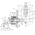
図1(リヤビュ−)及び図2は本発明の第1実施形態を示し、内燃機関01は、シリンダブロック02内形成されたシリンダボア03に沿って上下方向へ往復運動するピストン2と、該ピストン2の上下運動によって、ピストンピン3やピストン位置可変機構1の後述するリンク機構5を介して回転駆動するクランクシャフト4と、を備えている。図1中のピストン2の冠面2a上に一点鎖線で示す燃焼室境界線との間に隔成された空間は気筒内容積Vである。
In this embodiment, the present invention is applied to a single-cylinder
[First Embodiment]
FIG. 1 (rear view) and FIG. 2 show a first embodiment of the present invention. An
前記ピストン位置可変機構1は、複数のリンクからなる前記リンク機構5や、該リンク機構5の姿勢を変化させる位相変更機構6などから構成されている。
The piston
前記リンク機構5は、前記ピストン1にピストンピン3を介して連結された第1リンクであるアッパリンク7と、該アッパリンク7に第1連結ピン8を介して揺動可能に連結されると共にクランクシャフト4のクランクピン9に回転可能に連結された第2リンクであるロアリンク10と、該ロアリンク10に第2連結ピン11を介して揺動可能に連結されると共にコントロ−ルシャフト12の偏心カム部13に回転可能に連結された第3リンクであるコントロ−ルリンク14と、から構成されている。
The link mechanism 5 is connected to the
また、クランクシャフト4の前端部には、図1及び図2に示すように、駆動回転体である小径な第1ギヤ歯車15が固定されている一方、前記コントロールシャフト12の前端部側に従動回転体である大径な第2ギヤ歯車16が設けられ、前記第1ギヤ歯車15と第2ギヤ歯車16が噛み合ってクランクシャフト4の回転力が前記位相変更機構6を介してコントロールシャフト12に伝達されるようになっている。
Further, as shown in FIGS. 1 and 2, a small-diameter
前記第1ギヤ歯車15は、外径が第2ギヤ歯車16の外径の約半分の大きさになっており、したがって、前記前記クランクシャフト4の回転速度は、第1ギヤ歯車15と第2ギヤ歯車16の外径差によってコントロールシャフト12に半分の角速度に減速して伝達されるようになっている。
The outer diameter of the
前記コントロールシャフト12は、前記位相変更機構6によって、前記第2ギヤ歯車16に対する位相が変化し、つまり前記クランクシャフト4に対して相対回転位相が変更されるようになっている。
The phase of the
前記クランクシャフト4とコントロールシャフト12は、シリンダブロックに設けられた共通の前後2つの軸受17,18によって回転自在に支持されている。また、前記偏心カム部13は、前記コントロ−ルリンク14の下端部に形成された大径部にニードルベアリング19を介して回転自在に連結されている。
The
前記位相変更機構6は、例えば先に本出願人が出願した特開2012−225287号公報に記載された油圧式(ベーンタイプ)の位相変更機構と同じ構造であるから簡単に説明する。 The phase change mechanism 6 will be briefly described because it has the same structure as the hydraulic (vane type) phase change mechanism described in Japanese Patent Application Laid-Open No. 2012-225287 filed by the present applicant.
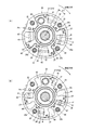
すなわち、この位相変更機構6は、図2及び図3A,B(フロントビュ−)に示すように、前記第2ギヤ歯車16が固定されたハウジング20と、該ハウジング20内に相対回転自在に収容され、前記コントロールシャフト12の一端部に固定されたベーンロータ21と、該ベーンロータ21を油圧によって正逆回転させる油圧回路22と、を備えている。
That is, as shown in FIGS. 2 and 3A, B (front view), the phase changing mechanism 6 is housed in a
該ハウジング20は、円筒状のハウジング本体20aの前端開口が円板状のフロントカバー23によって閉塞されていると共に、後端開口が円盤状のリアカバー24によって閉塞されている。また、ハウジング本体20aの内周面の周方向の約90°位置には、4つの隔壁であるシュー20bが内方に向かって突設されている。
In the
前記リアカバー24は、前記第2ギヤ歯車16の中央位置に両者一体に設けられ、外周部が4本のボルト25によって前記ハウジング本体20aとフロントカバー23に共締め固定されている。また、前記リアカバー24のほぼ中央には、前記ベーンロータ21の円筒部に外周に軸受される大径な軸受孔24aが軸方向に貫通形成されている。
The
前記ベーンロータ21は、中央にボルト挿通孔を有する円筒状のロータ26と、該ロータ26の外周面の周方向のほぼ90°位置に一体に設けられた4枚のベーン27とを備えている。
The
前記ロータ26は、前端側の小径筒部26aが前記フロントカバー23の中央支持孔に回転自在に支持されている一方、後端側の小径な円筒部26bが前記リアカバー24の軸受孔24aに回転自在に支持されている。
In the
また、ベーンロータ21は、前記ロータ26のボルト挿通孔に軸方向から挿通した固定ボルト28によってコントロールシャフト12の前端部に軸方向から固定されている。
The
また、前記各ベーン27は、各シュー20b間に配置されていると共に、各外面の軸方向に形成された細長い保持溝内に前記ハウジング本体20aの内周面に摺接するシール部材及び該シール部材をハウジング本体内周面方向に押圧する板ばねが夫々嵌着保持されている。
Each
また、この各ベーン27の両側と各シュー20bの両側面との間に、それぞれ4つの進角室40と遅角室41がそれぞれ隔成されている。
Further, four
前記油圧回路22は、図2に示すように、前記各進角室40に対して作動油の油圧を給排する第1油圧通路28と、前記各遅角室41に対して作動油の油圧を給排する第2油圧通路29との2系統の油圧通路を有し、この両油圧通路28,29には、供給通路30とドレン通路31とが夫々通路切換用の電磁切換弁32を介して接続されている。前記供給通路30には、オイルパン33内の油を圧送する一方向のオイルポンプ34が設けられている一方、ドレン通路31の下流端がオイルパン33に連通している。
As shown in FIG. 2, the
前記第1、第2油圧通路28,29は、前記フロントカバー23側に設けられた通路構成部の内部に形成されており、各一端部が前記通路構成部の前記ロータ26の小径筒部26aから内部の支持穴内に挿通配置された円柱部35を介して前記ロータ26内に連通している一方、他端部が前記電磁切換弁32に接続されている。
The first and second
前記第1油圧通路28は、各進角室40と連通する図外の4本の分岐路とを備えている一方、第2油圧通路29は、各遅角室41と連通する第2油路とを備えている。
The first
前記電磁切換弁32は、4ポート3位置型であって、内部の弁体が各油圧通路28,29と供給通路30及びドレン通路31とを相対的に切り替え制御するようになっていると共に、コントロールユニット36からの制御信号によって切り替え作動されるようになっている。
The
そして、前記電磁切換弁32の切り換え作動によって、前記各進角室40と各遅角室41に作動油を選択的に供給することによって前記ベーンロータ21(コントロールシャフト12)を前記クランクシャフト4に対して相対回転位相を変更させるようになっている。
The vane rotor 21 (control shaft 12) is supplied to the
また、前記各遅角室41内には、前記ベーンロータ21を遅角方向へ常時付勢する4本のコイルスプリング42がそれぞれ装着されている。
In each retarding
図4A〜D(リヤビュ−)は第2ギヤ歯車16とコントロ−ルシャフト12との相対回転位相を変化させた場合を示している。なお、この図では第1、第2ギヤ歯車15,16などは省略してある。
4A to 4D (rear views) show a case where the relative rotational phase between the
この相対回転位相は、本実施形態では、前述の位相変更機構6による相対回転位相変換制御により変化できるようになっているが、前記第2ギヤ歯車16とコントロ−ルシャフト12(偏心カム部13)との取り付け関係を相対的に変えることによって行うこともできる。
In this embodiment, the relative rotational phase can be changed by the relative rotational phase conversion control by the phase changing mechanism 6 described above, but the
この図4では、図1に示す第2ギヤ歯車16とコントロ−ルシャフト12の相対位相を変えない状態でクランクシャフト4を時計方向に回転して行き、クランクピン9が真上を向いた位置(クランク角X=0°;吸気(排気)上死点付近)からさらに1回転して再度クランクピン9が真上を向いた位置(X=360°;圧縮上死点付近)での姿勢を示す。このとき、ピストン2の位置(高さ)は圧縮上死点付近なので高い位置になっている。またこのとき、例えば、図3Aに示すように、偏心カム部13の偏心方向は、真上方向よりα1(例えば137°)だけ時計方向に遅角した位置となっている。
4, the
すなわち、図4(リヤビュ−)における偏心カム部13の回転方向はクランクシャフトとは逆の反時計方向なので、図4Aに示す場合は真上方向よりα1だけ遅角しているのである。このような場合、制御位相α1と呼ぶことにする。
図4Bは、図4Aに対してコントロ−ルシャフト12(偏心カム部13)の位相をさらに遅角側のα2(例えば180°)まで遅角させた位置、すなわち、偏心カム部13の偏心方向が真下付近になっている。(制御位相α2)
また、図4Cに示す場合は制御位相α3(例えば222°)、図4Dでは制御位相α4(例えば240°)と、さらにコントロ−ルシャフト12(偏心カム部13)の位相を時計方向に遅角させていった位置となっている。
That is, the rotation direction of the
FIG. 4B shows a position where the phase of the control shaft 12 (eccentric cam portion 13) is further retarded to α2 (for example, 180 °) on the retard side, that is, the eccentric direction of the
4C, the control phase α3 (eg, 222 °), the control phase α4 (eg, 240 °) in FIG. 4D, and the phase of the control shaft 12 (eccentric cam portion 13) are retarded clockwise. It is in the position where it went.
ここで、例えば、図4Cに示す制御位相α3と図4Dに示す制御位相α4の間を変換できる位相変更機構6の作動について図3A,Bに基づいて考察する。 Here, for example, the operation of the phase changing mechanism 6 capable of converting between the control phase α3 shown in FIG. 4C and the control phase α4 shown in FIG. 4D will be considered based on FIGS. 3A and 3B.
この図3はフロントビュ−なので、第2ギヤ歯車16の回転方向は図3中では時計方向となる。図3Aが位相変更機構6のベーンロータ21の最遅角位置(制御位相α4と対応)、同図Bが最進角位置(制御位相α3と対応)を示しており、この最遅角、最進角位置ともに最大拡巾のベーン27(27a)の両側部が隣接する各シュー20bの一側面と他側面に当接してストッパ(遅角側ストッパ、進角側ストッパ)により規制されるようになっている。
Since FIG. 3 is a front view, the rotation direction of the
ここで、前記ベーンロータ21は、各コイルスプリング42のばね力によって図3Aに示すように、最遅角位置付近で機械的に安定するようになっている。(つまり、デフォルト位置は最遅角位置)
位相変更機構6の位相変換角αTを、αT=α4−α3、例えば18°(=240°−222°)とすれば、α3⇔α4の変換での所望の変換角αT(18°)を実現できる。
Here, the
If the phase conversion angle αT of the phase change mechanism 6 is αT = α4-α3, for example, 18 ° (= 240 ° -222 °), a desired conversion angle αT (18 °) in the conversion of α3⇔α4 is realized. it can.
さらに、前述の最遅角位置(デフォルト位置)が、図4Dに示すα4と一致するように、ベーンロータ21とコントロ−ルシャフト12との取り付け位相を設定すると、所望の図4C⇔図4Dの位相変換(α3⇔α4)が実現できるのである。
Further, when the attachment phase between the
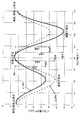
図5はピストン位置変化特性を示している。ここで、クランク角Xが0°では、クランクピン9が真上に位置しており、この付近で、ピストン2の吸気(または排気)上死点となっている。
FIG. 5 shows the piston position change characteristic. Here, when the crank angle X is 0 °, the
クランク角Xが0°から時計方向に回転し始めると、図外の排気弁は完全に閉じ、図外の吸気弁が開作動を開始し、図外の吸気ポ−トより新気(混合気)の吸入を行う。次に、クランク角Xが180°となった付近でピストン吸気下死点となり、この付近で吸気弁は閉じられる。ここで、吸気上死点から吸気下死点までを吸気行程という。 When the crank angle X starts to rotate clockwise from 0 °, the exhaust valve (not shown) is completely closed, the intake valve (not shown) starts to open, and fresh air (mixture) is started from the intake port (not shown). ). Next, the piston intake bottom dead center is reached in the vicinity of the crank angle X of 180 °, and the intake valve is closed in this vicinity. Here, the intake stroke is from the intake top dead center to the intake bottom dead center.
さらに、クランクシャフト4が回転すると、吸気弁は完全に閉じられると共に、筒内混合気が圧縮されて、クランク角Xが360°となった位置(クランクピン9が再度真上位置)の付近で、ピストン圧縮上死点になる。ここで、吸気下死点から圧縮上死点までを圧縮行程という。
Further, when the
その後、火花点火(または圧縮着火)が行なわれて燃焼が開始され、その燃焼圧がピストン2を押し下げていき、クランク角Xが540°付近で膨張下死点となる。ここで、圧縮上死点から膨張下死点までを膨張行程という。
Thereafter, spark ignition (or compression ignition) is performed and combustion is started. The combustion pressure pushes down the
この膨張下死点付近で、排気弁が開作動を開始し、ピストン2の再上昇とともに燃焼ガス(排気ガス)を図外の排気ポ−トより排出し、再び排気(吸気)上死点付近であるクランク角Xが720°(0°)の位置(クランクピン9が真上位置)に戻るのである。(ここで、膨張下死点から排気(吸気)上死点までを排気行程と呼ぶ。)
以上のように、4サイクル機関としての作動が行われ、クランク角(X)720°を1周期とする周期的な作動になっている。
Near this expansion bottom dead center, the exhaust valve starts to open, and when the
As described above, the operation as a four-cycle engine is performed, and the operation is periodic with a crank angle (X) of 720 ° as one cycle.
図5において、実線は図4Cの制御位相α3でのピストン位置特性(α3特性)を示し、破線は図4Dの制御位相α4でのピストン位置特性(α4特性)を示している。両特性とも、圧縮上死点でのピストン位置は略同一(Y0)で、吸気下死点位置は両特性で異なる。すなわち、圧縮上死点での気筒内容積Vは、両特性とも前記Y0により決まり、ほぼ同一(V0)となっている。 In FIG. 5, the solid line indicates the piston position characteristic (α3 characteristic) at the control phase α3 in FIG. 4C, and the broken line indicates the piston position characteristic (α4 characteristic) at the control phase α4 in FIG. 4D. In both characteristics, the piston position at the compression top dead center is substantially the same (Y0), and the intake bottom dead center position is different in both characteristics. That is, the cylinder internal volume V at the compression top dead center is determined by the Y0 for both characteristics and is substantially the same (V0).
このV0とは、圧縮上死点において、シリンダヘッド側の燃焼室内面形状と、ピストン2の冠面2aの形状と、シリンダブロック02の内径と、図外のヘッドガスケット内径などに囲まれた容積、つまり、圧縮上死点における気体(混合気)の容積になる。
This V0 is the volume surrounded by the shape of the combustion chamber on the cylinder head side, the shape of the
図5に示すα3特性では、吸気下死点のピストン位置はYC3であり、そこから圧縮上死点への長さ(圧縮ストロ−ク)はLC3であり、膨張下死点のピストン位置はYE3で、そこへの圧縮上死点からの長さ(膨張ストロ−ク)はLE3である。 In the α3 characteristic shown in FIG. 5, the piston position at the intake bottom dead center is YC3, the length from that to the compression top dead center (compression stroke) is LC3, and the piston position at the expansion bottom dead center is YE3. The length (expansion stroke) from the compression top dead center to this is LE3.
ここで、α3特性での機械圧縮比CであるC3と、同機械膨張比EであるE3について考察する。 Here, C3 which is the mechanical compression ratio C in the α3 characteristic and E3 which is the mechanical expansion ratio E will be considered.
ボア(シリンダ内径)の面積をSとすると、吸気下死点での気筒内容積VC3は、VC3=V0+S×LC3 となる。 When the area of the bore (cylinder inner diameter) is S, the cylinder internal volume VC3 at the intake bottom dead center is VC3 = V0 + S × LC3.
したがって、機械圧縮比C3=VC3÷V0=(V0+S×LC3)÷V0となる。 Therefore, the mechanical compression ratio C3 = VC3 ÷ V0 = (V0 + S × LC3) ÷ V0.
一方、機械膨張比E3=VE3÷V0=(V0+S×LE3)÷V0となる。 On the other hand, mechanical expansion ratio E3 = VE3 ÷ V0 = (V0 + S × LE3) ÷ V0.
ここで、VE3とは膨張下死点での気筒内容積である。
なお、α3特性の場合は、図5に示すように、LC3≒LE3であるため、機械圧縮比C3≒機械膨張比E3となっている。ここで、相対比D=機械膨張比E÷機械圧縮比Cと定義する。
Here, VE3 is the cylinder volume at the expansion bottom dead center.
In the case of the α3 characteristic, as shown in FIG. 5, since LC3≈LE3, mechanical compression ratio C3≈mechanical expansion ratio E3. Here, the relative ratio D = mechanical expansion ratio E ÷ mechanical compression ratio C is defined.
前記α3特性での相対比D3は、E3÷C3≒1となり、機械膨張比Eと機械圧縮比Cはほぼ同一のほぼ標準的な特性となっている。 The relative ratio D3 in the α3 characteristic is E3 ÷ C3≈1, and the mechanical expansion ratio E and the mechanical compression ratio C are substantially the same and almost standard characteristics.
すなわち、α3特性では、一般的な機関の通常のピストン位置変化特性(E=C、D=1)に近くなっている。 That is, the α3 characteristic is close to a normal piston position change characteristic (E = C, D = 1) of a general engine.
次に、前記α4特性での機械圧縮比CであるC4と、同機械膨張比EであるE4について考察する。 Next, C4 which is the mechanical compression ratio C in the α4 characteristic and E4 which is the mechanical expansion ratio E will be considered.
前記α3特性と同様に、機械圧縮比C4=VC4÷V0=(V0+S×LC4)÷V0となり、機械膨張比E4=VE4÷V0=(V0+S×LE4)÷V0 となる。 Similarly to the α3 characteristic, mechanical compression ratio C4 = VC4 ÷ V0 = (V0 + S × LC4) ÷ V0, and mechanical expansion ratio E4 = VE4 ÷ V0 = (V0 + S × LE4) ÷ V0.
ここで、α4特性の場合は、図5に示すように、LC4>LE4であるため、機械圧縮比C4>機械膨張比E4となっている。すなわち、相対比D4=LE4÷LC4<1であり、これは、機械圧縮比が機械膨張比より、相対的に大きいことを意味する。また、α3特性との対比でみると、C4>C3と機械圧縮比は大きく、E4<E3と機械膨張比は小さくなっている。 Here, in the case of the α4 characteristic, as shown in FIG. 5, since LC4> LE4, the mechanical compression ratio C4> the mechanical expansion ratio E4. That is, the relative ratio D4 = LE4 ÷ LC4 <1, which means that the mechanical compression ratio is relatively larger than the mechanical expansion ratio. Further, in comparison with the α3 characteristic, C4> C3 and the mechanical compression ratio are large, and E4 <E3 and the mechanical expansion ratio are small.
図6A〜Dに制御位相α4(ベーンロータ21の最遅角デフォルト位置、例えば240°)でのクランク角を変化した場合、図6E〜Hに制御位相α3(ベーンロータ21の最進角位置、例えば222°)でのクランク角を変化した場合の、それぞれの機構姿勢変化図を示している。(全てリアビュー)
ここで、図6のA及びEは吸気(排気)上死点での姿勢、B及びFは吸気下死点での姿勢、C及びGは圧縮上死点での姿勢、D及びHは膨張下死点での姿勢をそれぞれ示している。
6A to 6D, when the crank angle at the control phase α4 (the most retarded angle default position of the
Here, A and E in FIG. 6 are postures at the top dead center of intake (exhaust), B and F are postures at the bottom dead center of intake, C and G are postures at the top dead center of compression, and D and H are expansions. Each posture is shown at the bottom dead center.
図6E〜Hのα3特性の場合は、前述のように、LC3≒LE3であるため、機械圧縮比C3≒機械膨張比E3 (相対比D3≒1)となっている。 In the case of the α3 characteristic shown in FIGS. 6E to H, since LC3≈LE3 as described above, the mechanical compression ratio C3≈mechanical expansion ratio E3 (relative ratio D3≈1).
図6A〜Dのα4特性の場合は、前述のように、LC4>LE4であるため、機械圧縮比C4>機械膨張比E4 (相対比D4<1)となっている。そして、図6E〜Hのα3特性と比較すると、前述のように、LC4>LC3、LE4<LE3 となっている。 In the case of the α4 characteristic shown in FIGS. 6A to 6D, since LC4> LE4 as described above, mechanical compression ratio C4> mechanical expansion ratio E4 (relative ratio D4 <1). 6A to 6H, LC4> LC3 and LE4 <LE3 as described above.
なぜこのようなピストン位置変化特性になるかを考察する。吸気下死点における偏心カム部13の偏心回転方向αCについてみてみると、図6Bに示すα4特性でのαC4は、図6Fに示すα3特性でのαC3に対して、時計方向(遅角方向)に位相変化しており、つまり偏心カム部13の偏心円中心は、α3特性に対して相対的に、右上方に移動しており、これによりコントロールリンク14は第2連結ピン11を右上方に押し上げ、ロアリンク10を、クランクピン9を支点として時計方向に回転させ、それにより第1連結ピン8の位置は下がり、もってアッパリンク7によりピストン2は下方に引き下げられる。これにより、LC4>LC3となる。
The reason why such a piston position change characteristic is considered will be considered. Looking at the eccentric rotation direction αC of the
一方、膨張下死点における偏心カム部13の偏心回転方向αEについてみてみると、図6Dに示すα4特性でのαE4は、図6Hに示すα3特性でのαE3に対して、同様に時計方向(遅角方向)に変化しており、つまり偏心円中心は相対的に下方に移動しており、これによりコントロールリンク14は第2連結ピン11を左下方に引き下げ、ロアリンク10を、クランクピン9を支点として反時計方向に回転させ、これによって第1連結ピン8の位置は上がり、もってアッパリンク7によりピストン2は上方に押し上げられる。これにより、LE4<LE3 となる。
On the other hand, when looking at the eccentric rotation direction αE of the
すなわち、図5に示す制御位相α3と制御位相α4のピストン位置変化特性の差は、図6に示す偏心カム部13の偏心位相の違いによるリンク姿勢の違いにより生み出されるのである。
That is, the difference in the piston position change characteristic between the control phase α3 and the control phase α4 shown in FIG. 5 is generated by the difference in the link posture due to the difference in the eccentric phase of the
一方、圧縮上死点位置についてみてみると、制御位相α3と制御位相α4のピストン2の位置はほぼ同じ位置であることは、前述の通りであるが、これは以下の理由による。すなわち、図6C、Gに示す圧縮上死点姿勢に示すように、α3特性とα4特性とも、クランクピン9と第1連結ピン8とピストンピン3がほぼ一直線に配置されており、この配置によりロアリンク10の回動により第1連結ピン8が回動してもピストンピン2の位置変化は僅かに抑えられるためである。
On the other hand, when looking at the compression top dead center position, the position of the
このため、α3特性の圧縮上死点のピストン位置(図5のY03)、α4特性の圧縮上死点ピストン位置(図5のY04)は実質ほぼ同じ位置となり、それを前述のY0としたのである。 For this reason, the compression top dead center piston position of α3 characteristic (Y03 in FIG. 5) and the compression top dead center piston position of α4 characteristic (Y04 in FIG. 5) are substantially the same position, and this is Y0 described above. is there.
しかしながら、Y03とY04で有意差がでた場合は、気筒内容積を各々V03、V04として前述のV0のかわりに用いて、各々の機械圧縮比C3、C4、各々の機械膨張比E3、E4、各々の総対比D3、D4を求めれば良い。
〔本実施形態の性能効果〕
機関停止時には、位相変更機構6のベーンロータ21は、図3Aに示す最遅角位置(反時計方向)に各コイルスプリング42のばね力によって押し付けられ安定しており(デフォルト位置)、その時、制御位相は前述のα4となっている。
However, if there is a significant difference between Y03 and Y04, the in-cylinder volumes are used as V03 and V04, respectively, instead of the above-mentioned V0, and the respective mechanical compression ratios C3 and C4, the respective mechanical expansion ratios E3 and E4, What is necessary is just to obtain | require each total contrast D3 and D4.
[Performance effect of this embodiment]
When the engine is stopped, the
したがって、冷機始動時には、予めベーンロータ21の最遅角位置であるα4の特性(図5の破線)になっており、この特性による排気エミッションの低減効果が、前記デフォルト設定によって始動燃焼のまさに初期から得られる。(また位相変更機構6の電磁切換弁32の電気系統が断線などの故障があった場合にもこの位置を維持できるので、その場合でも前述の排気エミッション低減効果が得られるので所謂メカニカルフェールセーフ効果も持つ。)
すなわち、この特性による排気エミッション低減効果については、まず1つ目として、機械膨張比E4が小さくなっているので、膨張仕事が減った分、内燃機関から排出される排気ガス温度が高まるので、下流の触媒の暖機が促進されて、エミッション転化率が向上する。(ア)
一方、2つ目として、機械圧縮比C4は大きくなっているので、圧縮上死点での筒内ガス温度は上昇し、冷機運転時において問題となる燃焼不良を改善し、もって内燃機関そのものから排出されるエミッションを低減できる。(イ)
以上のE4小、C4大、D4小(=E4÷C4)により、(ア)の効果と(イ)の効果の相乗効果として、触媒下流のテールパイプから大気に放出される排気エミッション量を低減できる。
Therefore, at the time of cold start, the characteristic of α4 which is the most retarded angle position of the vane rotor 21 (broken line in FIG. 5) is set in advance, and the effect of reducing exhaust emission by this characteristic is from the very beginning of start combustion by the default setting. can get. (Also, this position can be maintained even when the electrical system of the
That is, regarding the exhaust emission reduction effect due to this characteristic, first, since the mechanical expansion ratio E4 is small, the temperature of exhaust gas discharged from the internal combustion engine increases as the expansion work is reduced. The catalyst warm-up is promoted to improve the emission conversion rate. (A)
On the other hand, second, since the mechanical compression ratio C4 is increased, the in-cylinder gas temperature at the compression top dead center is increased, which improves the combustion failure that becomes a problem during cold operation, and therefore from the internal combustion engine itself. Emissions can be reduced. (I)
By the above E4 small, C4 large, and D4 small (= E4 ÷ C4), the amount of exhaust emission released to the atmosphere from the tail pipe downstream of the catalyst is reduced as a synergistic effect of the effects of (a) and (b) it can.
ここで、相対比D4は1未満の小さな値となっており、これが小さいほど、機械膨張比が相対的に小さく、機械圧縮比が相対的に大きいことを意味しており、冷機時における排気エミッション性能の良さを示す指標とみることができる。 Here, the relative ratio D4 is a small value less than 1, which means that the smaller this is, the smaller the mechanical expansion ratio and the larger the mechanical compression ratio. It can be regarded as an index indicating good performance.
ところで、機関の暖機が完了すると、C4、E4、D4のままの状態では燃費が悪化する。なぜなら、機械膨張比E4が低いので、ピストン2による膨張仕事が低下し(ウ)、また機械圧縮比C4が高いので、暖機後では圧縮上死点温度が過度に高くなり、いわゆる冷却損失が増加し(エ)、もって以上の(ウ)(エ)による損失により燃費が悪化するのである。
By the way, when the warm-up of the engine is completed, the fuel consumption deteriorates in the state where C4, E4, and D4 remain unchanged. Because the mechanical expansion ratio E4 is low, the expansion work by the
また、機関運転状態が高負荷であれば、さらにノッキングやプレイグニッションという異常燃焼も誘発してしまい、一層燃費が悪化すると共に、トルクも低下するのである。 Further, if the engine operating state is a high load, abnormal combustion such as knocking and pre-ignition is further induced, and the fuel consumption is further deteriorated and the torque is also reduced.
したがって、暖機後においては、位相変更機構6の電磁切換弁32からの制御油圧によりベーンロータ21が最進角位置に変換し、α3の特性(図5の実線)に切替えるのである。
Therefore, after the warm-up, the
これにより、標準的な機械膨張比E3、標準的な機械圧縮比C3に復帰し、相対比D3はほぼ1となり通常のピストン位置変化特性と同等となるので、上記(ウ)(エ)による損失により燃費悪化したり、さらには異常燃焼が誘発されるのを抑制できる。 As a result, the standard mechanical expansion ratio E3 and the standard mechanical compression ratio C3 are restored, and the relative ratio D3 is almost 1, which is equivalent to the normal piston position change characteristic. As a result, it is possible to suppress the deterioration of fuel consumption and the induction of abnormal combustion.
なお、機関温度が冷機と暖機完了と中間にある場合は、その温度に応じて、低温になるほどベーンロータ21を遅角側へ変更して行き(α4に近づけて行き)、高温になるほど位相変更機構6によって進角側へ変更させていく(α3に近づけていく)ことによって、温度の変化毎に、排気エミッション性能と燃費性能を最適にバランスさせることができるのである。例えば、エミッションを充分に低い所定値に抑えつつ、可及的に燃費悪化を抑制することができる。
If the engine temperature is intermediate between the cold engine and the warm-up completion, the
なお、ピストン2の位置変化特性は、前述のように、クランク角720°を周期とする周期的な作動が行なわれ、上死点としては、クランク角が0°付近と360°付近の2度あらわれる。
As described above, the position change characteristic of the
クランク角360°付近の上死点(前述したY0)は、吸気弁、排気弁とも完全に閉弁された前述の圧縮上死点となっており、クランク角0°付近の上死点(Y’03、Y’04)は、排気弁が閉じ吸気弁作動が開始される、もうひとつの上死点である吸気(排気)上死点となっている。
この吸気(排気)上死点位置(Y’03、Y’04)は、圧縮上死点(Y0)より低くなっている。これは、図6A、Eの吸気上死点姿勢で示すように、α3とα4とも、クランクピン9と第1連結ピン8とピストンピン3が一直線上ではなく、逆く字形状に折れ曲がって配置されており、この配置によりピストン2の位置が前述のY0より低下し、またα3とα4との間のコントロ−ルシャフト12の位相差により、つまり逆く字の角度の差により、ピストン2の上死点位置にY’03、Y’04という有意差が生じているのである。(図5)
なお、ここで、吸排気弁の作動タイミングをクランク角で360°設定をずらした場合を想定してみると、圧縮上死点と吸気(排気)上死点が入れ替わったことになり、すなわち圧縮上死点でのピストン2の位置変化特性と、吸気(排気)上死点でのピストン2の位置変化特性とが入れ替わることになるが、こうした場合であっても、前述してきたような本発明の基本的効果を得ることができる。
The top dead center near the crank angle of 360 ° (Y0 mentioned above) is the compression top dead center where the intake valve and the exhaust valve are completely closed, and the top dead center near the
The intake (exhaust) top dead center position (Y′03, Y′04) is lower than the compression top dead center (Y0). As shown in the intake top dead center posture in FIGS. 6A and 6E, the
Here, assuming that the operation timing of the intake / exhaust valve is shifted by 360 ° in the crank angle, the compression top dead center and the intake (exhaust) top dead center are interchanged. The position change characteristic of the
一方、この設定をずらさない場合、つまり前述してきた第1実施形態(図1〜図6)そのものについては、以下の格別な効果が得られる。 On the other hand, when this setting is not shifted, that is, in the first embodiment (FIGS. 1 to 6) itself described above, the following special effects can be obtained.
すなわち、圧縮上死点では、Y0という高いピストン上死点位置となることから、機械圧縮比C、機械膨張比Eを大きく設定できるので、本発明の効果を充分高めることができる。 That is, since the piston top dead center position of Y0 is high at the compression top dead center, the mechanical compression ratio C and the mechanical expansion ratio E can be set large, so that the effect of the present invention can be sufficiently enhanced.
しかも、このような高いピストン位置に設定しても、圧縮上死点では吸排気弁が作動せず閉止状態が継続するため、ピストン2と吸排気弁が干渉する問題は発生しない。
Moreover, even if such a high piston position is set, the intake / exhaust valve does not operate at the compression top dead center and the closed state continues, so that the problem of interference between the
また、吸気(排気)上死点では、この付近で排気弁の閉作動および吸気弁の開作動が行なわれるので、仮にピストン位置がY0並に高いとこれら吸排気弁とピストン2との干渉が懸念されることになるが、前述のように、ピストン2の吸気(排気)上死点位置(Y’03、Y’04)が、圧縮上死点位置Y0より低いことから同干渉を回避できるのである。
Also, at the intake (exhaust) top dead center, the exhaust valve closing operation and the intake valve opening operation are performed in this vicinity. Therefore, if the piston position is as high as Y0, interference between the intake / exhaust valve and the
また、本実施形態では、図2に示すように、減速されるコントロールシャフト12側の大径な第2ギヤ歯車16に位相変更機構6が設置されているため、クランクシャフト4側の小径な第1ギヤ歯車15に位相変更機構6が設置したと想定した場合に対して、ベーンロータ21の外径などを適宜大きく設定することが可能になり、位相変更機構6によるベーンロータ21の変換動力を高めることができ、変換応答性を向上させたり、耐負荷能力を高めることも可能となる。
〔第2実施形態〕
図7から図8は本発明の第2実施形態を示し、第1実施形態に対して、ベーンロータ21の変換角とベーンロータ21とコントロ−ルシャフト12との相対回転位相を変更し、図4B、Cに示す制御位相α2と制御位相α3との間を変換できるようにしている。
Further, in the present embodiment, as shown in FIG. 2, the phase changing mechanism 6 is installed in the
[Second Embodiment]
7 to 8 show a second embodiment of the present invention. Compared to the first embodiment, the conversion angle of the
前記図3における変換角αTは、α3−α2(例えば、222°−180°=42°)とし、同様にベーンロータ21を遅角側に付勢するコイルスプリング42が設けられている。
The conversion angle αT in FIG. 3 is α3−α2 (for example, 222 ° −180 ° = 42 °), and similarly, a
ちなみに、第2実施形態では第1実施形態に対して、ベーンロータ21の変換角が拡大するが、ハウジング本体20aの突部であるストッパ部付近や拡巾ベーン27aの側面部を肉抜することによって対応すれば良い。あるいは、ベーン27の枚数を4枚から3枚に減少させても、変換角拡大を実現できる。
By the way, in the second embodiment, the conversion angle of the
そして、遅角側ストッパと拡巾ベーン27aが当接する最遅角位置(デフォルト位置)が、図4Cに示すα3の位置と一致するように、ベーンロータ21とコントロ−ルシャフト12の取り付け位相を設定すれば良い。
Then, the mounting phase of the
しかし、このように、ベーンロータ21の変換角拡大に伴い、ベーン27の枚数を減らしたりすると、位相変更機構6の油圧による変換動力(駆動力)が減少し、変換応答性悪化が懸念される。
However, if the number of
ところが、前述のように、減速される側の大径な第2ギヤ歯車16の方に位相変更機構6が設けられているため、ベーン27の外径などを適宜大きく設定することも可能になり、位相変更機構6によるベーンロータ21の変換動力を確保し、変換応答性の低下やベーンロータ21の位相保持能力の低下を抑制できるのである。
However, as described above, since the phase changing mechanism 6 is provided toward the large-diameter
図7はピストン位置変化特性を示し、実線は第1実施形態の図4Cの制御位相α3と同じ特性(α3特性)を示すが、本実施形態ではベーンロータ21の最遅角(デフォルト)位置での特性となる。図7の一点鎖線は図4Bに示す制御位相α2の特性(α2特性)で、これが本実施形態のベーンロータ21の最進角位置での特性となる。
FIG. 7 shows the piston position change characteristic, and the solid line shows the same characteristic (α3 characteristic) as the control phase α3 of FIG. 4C of the first embodiment, but in this embodiment, the
前記図4Bのα2の特性も、圧縮上死点のピストン2の位置はほぼ同一(前述のY0)であるが、吸気下死点位置と膨張下死点位置は、α3特性とは異なっている。
4B, the position of the
すなわち、図7に示すように、LC2<LE2であるため、機械圧縮比C2<機械膨張比E2となっており、相対比D2=LE2÷LC2>1であり、これは、機械膨張比が機械圧縮比よりも相対的に大きいことを意味する。 That is, as shown in FIG. 7, since LC2 <LE2, the mechanical compression ratio C2 <mechanical expansion ratio E2, and the relative ratio D2 = LE2 ÷ LC2> 1, which is a mechanical expansion ratio of mechanical It means that it is relatively larger than the compression ratio.
また、α3との対比でみると、C2<C3と機械圧縮比は小さく、LE2>LE3と機械膨張比は大きくなっている。 In comparison with α3, the mechanical compression ratio is small as C2 <C3, and the mechanical expansion ratio is large as LE2> LE3.
図8A〜Dは、制御位相α2での機構姿勢変化図を示している。前述のように、LC2<LE2であるため、機械圧縮比C2<機械膨張比E2、すなわち、相対比D2>1となっている。 8A to 8D show mechanism posture change diagrams at the control phase α2. As described above, since LC2 <LE2, mechanical compression ratio C2 <mechanical expansion ratio E2, that is, relative ratio D2> 1.
そして、図8E〜Hに記載した制御位相α3と比較すると、前述のように、LC2<LC3、LE2>LE3 となっている。 Compared with the control phase α3 described in FIGS. 8E to 8H, as described above, LC2 <LC3, LE2> LE3.
なぜこのような特性になるかを以下で考察する。図8B,Fに示す吸気下死点姿勢における偏心カム部13の偏心回転方向αCについて比較してみてみると、図8Bに示すα2特性でのαC2は、図8Fに示すα3特性でのαC3に対して、反時計方向(進角方向)に位相変化しており、つまり偏心円中心は左下方に移動しており、これによりコントロールリンク14は第2連結ピン11を相対的に左下方に引き下げ、ロアリンク10を、クランクピン9を支点として反時計方向に回転させ、それにより第1連結ピン8の位置は上がり、もってアッパリンク7によりピストン2は上方に押し上げられる。これにより、LC2<LC3 となる。
The reason why such characteristics are obtained will be discussed below. When comparing the eccentric rotation direction αC of the
一方、図8D、Hに示す膨張下死点姿勢における偏心カム部13の偏心回転方向αEについてみてみると、図8Dに示すα2特性でのαE2は、図8Hに示すα3特性でのαE3に対して、同様に反時計方向(進角方向)に変化しており、つまり偏心円中心は相対的に上方に移動しており、これによりコントロールリンク14は第2連結ピン11を右上方に押し、ロアリンク10を、クランクピン9を支点に時計方向に回転させ、それにより第1連結ピン8の位置は下がり、もってアッパリンク7によりピストンは下方に引き下げられる。これにより、LE2>LE3 となる。
On the other hand, looking at the eccentric rotation direction αE of the
すなわち、図7に示す制御位相α3と制御位相α2のピストン位置変化特性の違いは、図8に示す偏心カム部13の偏心回転方向の違いによるリンク姿勢の違いにより生み出されるのである。
〔本実施形態の性能効果〕
機関の暖機後には、位相変更機構6のベーンロータ21は電磁切換弁32からの制御油圧により最進角位置に変換され、α2の特性、すなわち、機械圧縮比C2は小さく、機械膨張比E2が大きい特性となる。
That is, the difference in the piston position change characteristic between the control phase α3 and the control phase α2 shown in FIG. 7 is generated by the difference in the link posture due to the difference in the eccentric rotation direction of the
[Performance effect of this embodiment]
After the engine is warmed up, the
ここで、機械膨張比E2が大きいことから、燃焼圧がピストンを押し下げることで行なう仕事を増やすことができ、これにより燃費を向上させることができる。 Here, since the mechanical expansion ratio E2 is large, the work performed when the combustion pressure pushes down the piston can be increased, thereby improving the fuel consumption.
一方、このような機関の暖機後においては、機械圧縮比が高いと圧縮上死点での筒内ガス温度が過度に高くなって冷却損失が増えてしまう懸念があるが、本実施形態のように、機械圧縮比C2が低下しているので、このような冷却損失の発生を抑制することで一層燃費(熱効率)を向上させることができる。 On the other hand, after the engine is warmed up, if the mechanical compression ratio is high, there is a concern that the in-cylinder gas temperature at the compression top dead center becomes excessively high and the cooling loss increases. As described above, since the mechanical compression ratio C2 is reduced, the fuel consumption (thermal efficiency) can be further improved by suppressing the occurrence of such a cooling loss.
また、機関高負荷ではこの高機械圧縮比によりノッキングなどの異常燃焼が生じ易いが、これも機械圧縮比低下によって回避することができるのである。 Further, abnormal combustion such as knocking is likely to occur due to this high mechanical compression ratio at a high engine load, but this can also be avoided by lowering the mechanical compression ratio.
ここで、前述した従来の技術(特開2002−276446号公報)でも機械圧縮比を低下制御することでノッキングを防止できるが、追随して機械膨張比も低下してしまい、燃費悪化やトルク低下を伴う。さらには、機械膨張比低下による排温上昇に伴い、触媒が熱劣化してしまうという問題が生じる。 Here, knocking can also be prevented by controlling the mechanical compression ratio to be lowered even with the above-described conventional technique (Japanese Patent Laid-Open No. 2002-276446), but the mechanical expansion ratio is also lowered and the fuel consumption is deteriorated and the torque is lowered. Accompanied by. Furthermore, with the increase in exhaust temperature due to the decrease in the mechanical expansion ratio, there arises a problem that the catalyst is thermally deteriorated.
これに対して、本実施形態では高機械膨張比のため、これらの問題を回避できる。 In contrast, in the present embodiment, these problems can be avoided because of the high mechanical expansion ratio.
ところで、本実施形態において、仮に冷機時においても、このようなピストン位置変化特性であったとすると、排気エミッション面から不都合が生じる。すなわち、機械膨張比E2が大きいので、膨張仕事が増える分、機関本体から排出される排気ガス温度が低下してしまい、下流の触媒の暖気が進まず、触媒による排気エミッション転化性能が低下する(カ)。 By the way, in this embodiment, if it is such a piston position change characteristic even at the time of cold, inconvenience arises from the aspect of exhaust emission. That is, since the mechanical expansion ratio E2 is large, the temperature of exhaust gas discharged from the engine main body is lowered by the amount of expansion work, and the warming of the downstream catalyst does not progress, and the exhaust emission conversion performance by the catalyst is lowered ( F).
さらに、機械圧縮比が低いので、冷機時において圧縮上死点での筒内ガス温度も相対的に低く、燃焼が悪いので機関本体そのものから排出されるエミッションも増加する(キ)。 Furthermore, since the mechanical compression ratio is low, the in-cylinder gas temperature at the compression top dead center is relatively low during cold operation, and the combustion is poor, so that the emissions discharged from the engine body itself increase.
以上の2つの(カ)(キ)により、触媒下流のテ−ルパイプからの大気に排出エミッションが増加してしまう。 Due to the above two (f) and (ki), emission emissions increase from the tail pipe downstream of the catalyst to the atmosphere.
そこで、冷機時は、α3特性のような通常のピストン位置変化特性にするのである。これにより、冷機時において大気に排出される排気エミッション増加を回避しつつ、前記暖機後の燃費低減などの効果を得ることができるのである。 Therefore, when the engine is cold, a normal piston position change characteristic such as the α3 characteristic is used. As a result, it is possible to obtain an effect such as a reduction in fuel consumption after the warm-up while avoiding an increase in exhaust emission exhausted to the atmosphere during cold operation.
なお、冷機時と暖機後の間の中間の温度(暖機途中)においては、位相変更機構6のベーンロータ21の回転位相を制御し、低温になるほどα3に近づけていき、高温になるほどα2に近づけていくように制御するのである。
Note that at the intermediate temperature between the time of cooling and the time after warming up (while warming up), the rotational phase of the
これにより、温度毎に燃費性能と排気エミッション性能を最適にバランスされることができる。例えば、排気エミッションを抑えつつ可及的に燃費を向上することができる。
〔第3実施形態〕
図9及び図10は本発明の第3実施形態を示し、第1実施形態や第2実施形態に対して、ベーンロータ21の変換角とベーンロータ21とコントロ−ルシャフト12の相対回転位相をさらに変更し、図4における制御位相α1と制御位相α4との間を変換できるようにした。
Thereby, the fuel efficiency performance and the exhaust emission performance can be optimally balanced for each temperature. For example, fuel consumption can be improved as much as possible while suppressing exhaust emission.
[Third Embodiment]
9 and 10 show a third embodiment of the present invention, which further changes the conversion angle of the
図3における変換角αTは、α4−α1(例えば、240°−137°=103°)と一層大きくなる。ベーン27の枚数を2枚に減少させて変換角拡大をしても良いが、本実施形態では、位相変更機構として、特開2012−197755号公報や特開2012−180816号公報に記載されているような電動式のものを用いたものである。
The conversion angle αT in FIG. 3 is further increased to α4-α1 (for example, 240 ° -137 ° = 103 °). Although the conversion angle may be expanded by reducing the number of
前記2つの公報に記載の位相変更機構によれば、電動モータの回転により減速機構を介して、カムシャフトとタイミングスプロケットとの位相を変換する機構となっているが、本実施形態では、このカムシャフトの代わりに前記コントロールシャフト12を、タイミングスプロケットの代わりに前記第2ギヤ歯車16を用いている。このように構成することによって、ベーンとハウジングの干渉などの機構レイアウトからの変換角制約はなくなり、前記2つの公報に記載されているように、自在に設定したストッパ凸部とストッパ凹部の関係のみで最遅角と最進角の回動規制が可能になる。
According to the phase change mechanism described in the above two publications, it is a mechanism that converts the phase between the camshaft and the timing sprocket via the speed reduction mechanism by the rotation of the electric motor. The
本実施形態では、これにより、電動式位相変更機構の出力軸の最進角位相をα1、最遅角位相をα4に設定している。 In this embodiment, this sets the most advanced angle phase of the output shaft of the electric phase change mechanism to α1 and the most retarded angle phase to α4.
また、第1・第2実施形態と同様にコントロ−ルシャフト12を遅角方向に付勢する図外の付勢手段も設けられている。
Further, as in the first and second embodiments, a biasing means (not shown) for biasing the
図9にはピストン位置変化特性を示し、破線は制御位相α4での特性(最遅角)を示し、これは第1実施形態の図5のα4特性と同じ特性で、実線の方は制御位相α1での特性(最進角)で、図4の制御位相α1に対応している。 FIG. 9 shows the piston position change characteristic, the broken line shows the characteristic (maximum retardation angle) at the control phase α4, which is the same characteristic as the α4 characteristic of FIG. 5 of the first embodiment, and the solid line shows the control phase. The characteristic at α1 (the most advanced angle) corresponds to the control phase α1 in FIG.
この図9から分かるように、制御位相α1のピストン位置変化特性では、圧縮ストロ−クLC1は充分小さく、膨張ストロ−クLE1は充分大きくなっている。したがって、機械圧縮比C1は充分小さく、機械膨張比E1は充分大きくなっており、相対比D1(E1÷C1)が1を充分超えた大きな値になっている。 As can be seen from FIG. 9, in the piston position change characteristic of the control phase α1, the compression stroke LC1 is sufficiently small and the expansion stroke LE1 is sufficiently large. Therefore, the mechanical compression ratio C1 is sufficiently small, the mechanical expansion ratio E1 is sufficiently large, and the relative ratio D1 (E1 ÷ C1) is a large value sufficiently exceeding 1.
図10A〜Dは制御位相α1での機構姿勢変化図を示し、図6、図8同様に、Aは吸気(排気)上死点、Bは吸気下死点、Cは圧縮上死点、Dは膨張下死点での各姿勢を示す。
同図Bに示す吸気下死点姿勢での偏心カム部13の偏心回転方向αC1についてみてみると、コントロールリンク14の方向とほぼ逆方向になっている。このため、コントロールリンク14及び第2連結ピン11はほぼ最大限左下方向に引き下げられ、ロアリンク10はクランクピン9を中心に反時計方向にほぼ最大限位相変化し、それに伴い、第1連結ピン8はほぼ最大限上方に移動し、もってアッパリンク7によりピストン2はほぼ最大限上方に押し上げられる。
FIGS. 10A to 10D show mechanism posture change diagrams at the control phase α1, and similarly to FIGS. 6 and 8, A is an intake (exhaust) top dead center, B is an intake bottom dead center, C is a compression top dead center, D Indicates each posture at the expansion bottom dead center.
Looking at the eccentric rotation direction αC1 of the
これにより、LC1は充分小さく、且つほぼ最大限小さくなる。(LC1<LC2<LC3<LC4)
一方、図10Dに示す膨張下死点姿勢で偏心カム部13の偏心回転方向αE1についてみてみると、コントロールリンク14の方向とほぼ同方向になっている。このため、コントロールリンク14及び第2連結ピン11はほぼ最大限右上方向に押し上げられ、ロアリンク10はクランクピン3を中心に時計方向にほぼ最大限界位相変化し、それに伴い、第1連結ピン8はほぼ最大限下方に移動し、もってアッパリンク7によりピストン2はほぼ最大限下方に引き下げられる。これにより、LE1は充分に大きく、且つほぼ最大限に大きくなる。(LE1>LE2>LE3>LE4)
すなわち、相対比D1(=LE1/LC1)も充分大きく、かつほぼ最大限大きくなる。(D1>D2>D3>D4)
これらの特徴は、偏心カム部13の偏心回転方向によるリンク姿勢の違いにより生み出されるのである。
〔本実施形態の性能効果〕
内燃機関の暖機完了後には、電動式の位相変更機構により偏心カム部13は最進角位置に変換され、α1の特性、すなわち、機械圧縮比C1は充分に、かつほぼ最大限に小さく、機械膨張比E1は充分に、かつほぼ最大限に大きい特性に制御される。
As a result, LC1 is sufficiently small and almost maximally small. (LC1 <LC2 <LC3 <LC4)
On the other hand, when the eccentric rotation direction αE1 of the
That is, the relative ratio D1 (= LE1 / LC1) is also sufficiently large and almost maximized. (D1>D2>D3> D4)
These characteristics are produced by the difference in the link posture depending on the eccentric rotation direction of the
[Performance effect of this embodiment]
After the warm-up of the internal combustion engine is completed, the
ここで、機械膨張比E1がほぼ最大限に大きいことから、燃焼圧がピストンを押し下げることで行なう仕事をほぼ最大限増やすことができる。 Here, since the mechanical expansion ratio E1 is almost as large as possible, the work performed by the combustion pressure pushing down the piston can be increased almost as much as possible.
一方、このような暖機完了後においては、圧縮上死点での筒内ガス温度が過度に高くなって、冷却損失が増えてしまう懸念があるが、本実施形態のように、機械圧縮比C1がほぼ最大限低下できるので、このような冷却損失の発生を充分に抑制することができる。 On the other hand, after completion of such warm-up, there is a concern that the in-cylinder gas temperature at the compression top dead center becomes excessively high and the cooling loss increases, but as in this embodiment, the mechanical compression ratio Since C1 can be reduced almost as much as possible, the occurrence of such a cooling loss can be sufficiently suppressed.
また、機関高負荷でのノッキングなどの異常燃焼も、ほぼ最小の機械圧縮比C1により充分抑制しつつ、ほぼ最大の機械膨張比E1により、燃費を充分向上できる。さらには、ほぼ最大の機械膨張比E1により排温(高温の高負荷排温)を充分低下させ、触媒の熱劣化を充分に抑制できる。 Abnormal combustion such as knocking at a high engine load can be sufficiently suppressed by the substantially minimum mechanical compression ratio C1, and the fuel efficiency can be sufficiently improved by the almost maximum mechanical expansion ratio E1. Furthermore, the exhaust temperature (high temperature exhaust heat exhaust temperature) can be sufficiently lowered by the substantially maximum mechanical expansion ratio E1, and the thermal deterioration of the catalyst can be sufficiently suppressed.
以上のような、十分な膨張仕事と冷却損失低減により、燃費(熱効率)を十分向上させたり、高負荷においては、さらに十分に排温を低下させ触媒熱劣化を防止したりできる。 By sufficient expansion work and cooling loss reduction as described above, fuel consumption (thermal efficiency) can be sufficiently improved, and at high loads, exhaust temperature can be further sufficiently reduced to prevent catalyst thermal deterioration.
ここで、相対比D1(=E1÷C1)について見てみると、前述のように、1を超えた充分大きな値になっており、これが大きいほど、機械膨張比が相対的に高く、機械圧縮比が相対的に低いことを意味しており、燃費性能などにおける前述の効果の高さを示す指標とみることができる。 Here, as for the relative ratio D1 (= E1 ÷ C1), as described above, it is a sufficiently large value exceeding 1, and as this is larger, the mechanical expansion ratio is relatively higher and the mechanical compression is higher. This means that the ratio is relatively low, and can be regarded as an index indicating the height of the above-described effect in fuel efficiency.
冷機時においては、仮にこのようなピストン位置変化特性(ほぼ最小機械圧縮比、ほぼ最大機械膨張比、ほぼ最大相対比)であったとすると、排気エミッション面から大きな不都合が生じる。 If it is such a piston position change characteristic (approximately the minimum mechanical compression ratio, approximately the maximum mechanical expansion ratio, and approximately the maximum relative ratio) at the time of cold, a great inconvenience occurs from the exhaust emission surface.
すなわち、機械膨張比E1がほぼ最大なので、膨張仕事が充分に増加する分、機関本体から排出される排気ガス温度が過度に低下してしまい、後流の触媒での暖気が進まずエミッション転化性能が著しく低下する。 That is, since the mechanical expansion ratio E1 is almost the maximum, the exhaust gas temperature exhausted from the engine body is excessively reduced by a sufficient increase in expansion work, so that the warm air in the downstream catalyst does not progress and the emission conversion performance. Is significantly reduced.
さらに、機械圧縮比がほぼ最小なので、冷機時において圧縮上死点での筒内ガス温度が過度に低下し、燃焼が著しく悪化し、機関本体から排出されるエミッションも著しく増加する。これらにより、触媒下流のテールパイプからの大気に排出エミッションが著しく増加してしまうのである。 Further, since the mechanical compression ratio is almost minimum, the in-cylinder gas temperature at the compression top dead center is excessively lowered during cold operation, the combustion is significantly deteriorated, and the emission discharged from the engine body is also significantly increased. As a result, the emission emission from the tail pipe downstream of the catalyst is significantly increased.
そこで、冷機時は、α4のように逆に機械圧縮比Cが大きく、機械膨張比Eが小さなピストン位置変化特性に変換するのである。これによって、第1実施形態と同様に、燃焼改善及び排温向上の効果により、大気に排出される排気エミッションを逆に大幅に低減し、且つ通常の一般的なピストン位置変化特性(例えばα3のような 機械圧縮比C=機械膨張比E となる特性)よりも、さらに排気エミッションを低減できる。すなわち、相対比D4は、1より低い値であり、これが小さいほど、膨張比が相対的に小さく、圧縮比が相対的に大きいことを意味しており、排気エミッション性能の良さを示す指標とみることができるのは前述の通りである。 Therefore, when the engine is cold, it is converted into a piston position change characteristic in which the mechanical compression ratio C is large and the mechanical expansion ratio E is small like α4. As a result, similar to the first embodiment, the exhaust emission discharged into the atmosphere is greatly reduced by the effect of improving combustion and exhaust temperature, and a normal general piston position change characteristic (for example, α3) Exhaust emissions can be further reduced than the mechanical compression ratio C = mechanical expansion ratio E. That is, the relative ratio D4 is a value lower than 1, which means that the smaller this is, the smaller the expansion ratio is, and the larger the compression ratio is, and this is regarded as an index indicating the good exhaust emission performance. As described above, this can be done.
以上により、第1実施形態と同じく、暖機後の燃費をほぼ最大限向上できるとともに、冷機時の排気エミッションも低減できるのである。
この効果は言い換えると、暖機後には相対比を1より大きなD1まで高めて燃費効果を高め、冷機時には相対比を1より小さなD4まで下げて冷機時排気エミッションを向上させているのである。
As described above, as with the first embodiment, the fuel efficiency after warm-up can be improved to the maximum extent, and exhaust emissions during cold-down can be reduced.
In other words, after warming up, the relative ratio is increased to D1 greater than 1 to increase the fuel efficiency, and when cold, the relative ratio is decreased to D4 smaller than 1 to improve exhaust emissions during cold.
なお、冷機時と暖機完了後の間の中間の温度(暖機中)においては、電動式位相変更機構の出力軸位相(偏心カム部13の位相)を高変換角制御し、低温になるほど制御位相α4に近づけていき、高温になるほど制御位相 α1に近づけていくように制御するのである。 Note that, at an intermediate temperature between the time of cooling and after the completion of warming up (during warming up), the output shaft phase (phase of the eccentric cam portion 13) of the electric phase change mechanism is subjected to high conversion angle control, and the temperature becomes lower. Control is performed so as to approach the control phase α4 and closer to the control phase α1 as the temperature becomes higher.
これにより、温度毎に燃費性能とエミッション性能を高次元でバランスさせることができる。この場合、温度によらず高応答変換が可能な電動式位相変更機構を用いているので、油圧式の位相変更機構に対して変換遅れがなく、安定的な効果が得られるのである。 Thereby, fuel efficiency performance and emission performance can be balanced at a high level for each temperature. In this case, since an electric phase change mechanism capable of high response conversion regardless of temperature is used, there is no conversion delay with respect to the hydraulic phase change mechanism, and a stable effect can be obtained.
例えば、温度の変化毎に安定的に排気エミッションを低下させつつ、燃費を最大限向上することができる。 For example, the fuel consumption can be improved to the maximum while the exhaust emission is stably reduced for every change in temperature.
さらに、本実施形態では、過渡運転状態においても、電動式の位相変更機構による高応答大変換角位相制御を行うことによって種々の機関性能を高めることができ、例えば急加速時における、過渡トルクを向上できる。 Furthermore, in this embodiment, even in a transient operation state, various engine performances can be improved by performing high response large conversion angle phase control by an electric phase change mechanism. For example, transient torque during sudden acceleration can be increased. It can be improved.
機械圧縮比低減により耐ノック性向上ができることは前述の通りだが、機械圧縮比低減に伴って吸入ストロ−ク(≒圧縮ストロ−ク)が低下する傾向があり、充填効率が低下してしまう場合も考えられる。 As described above, the knock resistance can be improved by reducing the mechanical compression ratio. However, when the mechanical compression ratio is reduced, the suction stroke (≈compression stroke) tends to decrease, and the filling efficiency decreases. Is also possible.
したがって、過渡トルクを向上させるためには、ノッキングを抑制しつつ可及的に最大限充填効率を高める必要があることから、加速過渡の瞬時において、最適に、すなわち瞬時の過渡トルクが最大になるように機械圧縮比を適宜補正制御することが求められる場合もある。 Therefore, in order to improve the transient torque, it is necessary to increase the filling efficiency as much as possible while suppressing knocking. Therefore, the instantaneous transient torque is maximized at the moment of acceleration transient. Thus, it may be required to appropriately correct and control the mechanical compression ratio.
ここで、近年増加してきたタ−ボなどの過給器を用いる場合には、さらに過給圧(大きいノッキングも発生し易い)も過渡変化するので、これも考慮してノッキングを抑制しつつ可及的に最大限充填効率高めることができる機械圧縮比に瞬時に制御することが求められる場合がある。 Here, when using a turbocharger such as a turbo, which has been increasing in recent years, the supercharging pressure (which tends to cause large knocking) also changes transiently. It may be required to instantaneously control the mechanical compression ratio that can maximize the filling efficiency as much as possible.
これらの要求に対し、本実施形態では、前述のように電動式位相変更機構を用いているので、機関油圧や機関温度によらず高応答の変換ができるため過渡トルク向上効果を充分に得ることができるのである。 In response to these requirements, in the present embodiment, since the electric phase change mechanism is used as described above, a high response conversion can be performed regardless of the engine oil pressure or the engine temperature, so that a sufficient transient torque improvement effect can be obtained. Can do it.
また、例えば、このように加速して高負荷域になった後、低負荷域に移行した場合でも、電動式位相変更機構により瞬時に高機械膨張比にできるので、燃費効果も素早く得られる。 In addition, for example, even when the vehicle accelerates to the high load region and then shifts to the low load region, the high-mechanical expansion ratio can be instantaneously achieved by the electric phase change mechanism, so that the fuel efficiency can be obtained quickly.
以上のように、大変換角の位相変更機構の高応答位相制御を行うことで、種々の機関性能を高めることができるのである。
〔第4実施形態〕
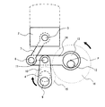
図11は第4実施形態を示し、リンク機構5を変更したものであって、前記コントロ−ルシャフト12の偏心カム部13と連結したコントロールリンク14に、2つの第1連結ピン8と第2連結ピン11が設けられている点などが第1〜第3実施形態と異なっている。
As described above, various engine performances can be improved by performing the high response phase control of the phase change mechanism with a large conversion angle.
[Fourth Embodiment]
FIG. 11 shows a fourth embodiment in which the link mechanism 5 is changed, and the two first connection pins 8 and the second connection are connected to the
すなわち、このリンク機構5は、前記ピストン2にピストンピン3を介して連結されたアッパリンク7と、前記アッパリンク7に第1連結ピン8を介して揺動可能に連結されると共にコントロ−ルシャフト12の偏心カム部13に揺動可能に連結されたコントロールリンク14と、該コントロールリンク14に第2連結ピン11を介して揺動可能に連結されると共にクランクシャフト4のクランクピン9に回転可能に連結されたロアリンク10と、から構成されている。
That is, the link mechanism 5 includes an
そして、クランクシャフト4の回転は、第1〜第3実施形態と同様に、第1ギヤ歯車15を介して第2ギヤ歯車16(コントロールシャフト12)に半分の角速度に減速されて伝達される。
Then, the rotation of the
この第2ギヤ歯車16とコントロ−ルシャフト12は、第1〜第3実施形態と同様の位相可変機構6によって相対回転位相を変化できるようになっている。
The
図11はピストン2の吸気下死点付近の姿勢、すなわちクランクピン9が真下を向いた位置を示している。
FIG. 11 shows the posture of the
ここで、偏心カム部13の偏心回転方向はほぼ真上であり、クランクピン9、第2連結ピン11、ピストンピン3はほぼ一直線上に真上を向いている。これにより、ピストン2の位置はやや下方にシフトしており、吸入ストロ−ク及び圧縮ストロ−クが増大している。
Here, the eccentric rotation direction of the
何故なら、偏心カム部13の上方移動により、コントロールリンク14は、第2連結ピン11を支点として反時計方向に傾き、もって第1連結ピン8は相対的に下方に移動し、アッパリンク7はピストン2を引き下げるからである。
Because of the upward movement of the
ここで、前記ピストン下死点付近は、膨張下死点側でなく吸気下死点側になるように吸排気弁タイミングが設定されており、前述の圧縮ストロ−ク増大により、高機械圧縮比に設定することができる。 Here, the intake / exhaust valve timing is set so that the vicinity of the piston bottom dead center is not the expansion bottom dead center side but the intake bottom dead center side, and the high mechanical compression ratio is increased by increasing the compression stroke. Can be set to
次に、膨張下死点について考察すると、クランクシャフト4が時計方向に360°(1回転)回転すると、クランクピン9は再び真下を向いた位置、すなわち膨張下死点付近となる。偏心カム部13は、一対の第1、第2ギヤ歯車15,16を介して、半分の角速度で反時計方向に180°(360°の半分)に回転することから、偏心カム部13の偏心回転方向が今度はほぼ真下となる。
Next, the expansion bottom dead center will be considered. When the
これにより、ピストン位置は、今度はやや上方にシフトすることになる。(膨張ストロ−ク減少)。何故なら、偏心カム部13の下方移動により、コントロールリンク14は、第2連結ピン11を支点として時計方向に傾き、もって第1連結ピン8は相対的に上方に移動し、アッパリンク7はピストン2を押し上げるからである。
As a result, the piston position is now shifted slightly upward. (Expansion stroke reduction). This is because when the
このようにして、膨張ストロ−ク減少により、低機械膨張比に設定することができる。 In this way, a low mechanical expansion ratio can be set by reducing the expansion stroke.
ここでいう膨張ストロ−クや圧縮ストロ−クとは、圧縮上死点でのピストン位置からのストロ−クであり、したがって、第1実施形態のα4特性と同様に、高機械圧縮比で低機械膨張比となるのである。 The expansion stroke and the compression stroke referred to here are strokes from the piston position at the compression top dead center, and therefore, as with the α4 characteristic of the first embodiment, the high mechanical compression ratio is low. This is the mechanical expansion ratio.
以上説明してきたように、実施形態1〜3と異なるリンク機構5であっても、機械圧縮比と機械膨張比を異ならせることができる。 As described above, the mechanical compression ratio and the mechanical expansion ratio can be made different even in the link mechanism 5 different from the first to third embodiments.
さらに前述の位相変更機構による種々の位相変換や取り付け位相の変更を行なえば、機械圧縮比と機械膨張比の両方を異ならせつつ適宜変化できるのは、第1〜第3実施形態と同様である。 Further, if various phase conversions and attachment phase changes are performed by the above-described phase change mechanism, the mechanical compression ratio and the mechanical expansion ratio can be changed appropriately as in the first to third embodiments. .
本発明は、前記各実施形態の構成に限定されるものではなく、例えば各実施形態では単一気筒の内燃機関を示したが、2気筒や3気筒や4気筒などの多気筒に適用しても構わない。その場合、全気筒のピストン作動特性を単一ないし複数の位相変更機構により変化でき、もって全気筒を所望の機械圧縮比、機械膨張比に制御することが可能である。さらに、ガソリン機関のような火花点火エンジンだけでなく、ディ−ゼル機関のような圧縮着火エンジンに適用できるのが言うまでもない。 The present invention is not limited to the configuration of each of the above-described embodiments. For example, each embodiment shows a single-cylinder internal combustion engine. However, the present invention is applied to multi-cylinders such as 2-cylinder, 3-cylinder, and 4-cylinder. It doesn't matter. In this case, the piston operating characteristics of all the cylinders can be changed by a single or a plurality of phase changing mechanisms, so that all the cylinders can be controlled to a desired mechanical compression ratio and mechanical expansion ratio. Furthermore, it goes without saying that the present invention can be applied not only to a spark ignition engine such as a gasoline engine but also to a compression ignition engine such as a diesel engine.
また、前記各実施形態では、ピストン2からクランクシャフト4までのリンク機構5として2つの機構タイプを示したが、このリンク機構などの構成は本発明の主旨から逸脱しない範囲で適宜選択すれば良く、特に限定されるものではない。
In each of the above embodiments, two mechanism types are shown as the link mechanism 5 from the
前記クランクシャフト4の回転を半分の角速度に減速して偏心カム部13に伝える減速機構として一対の第1、第2ギヤ歯車15,16の例を示したが、これに限定されるものではない。
Although an example of the pair of first and second gear gears 15 and 16 has been shown as a speed reduction mechanism that decelerates the rotation of the
また、各実施形態では、クランクシャフト4の回転方向と偏心カム部13の回転方向が逆方向になるが、同方向としても良い。例えば、クランクシャフト4側の第1ギヤ歯車15の回転をタイミングベルト(タイミングチェ−ン)を介して、半分の角速度に減速して、偏心カム部13側の第2ギヤ歯車16に伝達するようにしても良い。
Moreover, in each embodiment, although the rotation direction of the
この場合は、クランクシャフト4の回転方向と偏心カム部13の回転方向が同方向となり、クランクシャフト4の回転(横軸)に対するピストン位置変化特性(縦軸)は左右に裏返るが、本発明の主旨を実現できる。
以上説明してきたように、本発明の主旨から逸脱しない範囲であれば構成は特に限定されるものではない。
In this case, the rotation direction of the
As described above, the configuration is not particularly limited as long as it does not depart from the gist of the present invention.
01…内燃機関
02…シリンダブロック
03…ボア
1…ピストン位置可変機構
2…ピストン
3…ピストンピン
4…クランクシャフト
5…リンク機構
6…位相変更機構
7…アッパリンク(第1リンク)
8…第1連結ピン
9…クランクピン
10…ロアリンク(第2リンク)
11…第2連結ピン
12…コントロールシャフト
13…偏心カム部
14…コントロールリンク(第3リンク)
15…第1ギヤ歯車(駆動回転体)
16…第2ギヤ歯車(従動回転体)
DESCRIPTION OF
8 ...
DESCRIPTION OF
15 ... 1st gear gear (drive rotating body)
16 ... Second gear gear (driven rotor)
Claims (8)
前記ピストンの圧縮上死点での気筒内容積をVO、ピストンの吸気下死点での気筒内容積をVC、ピストンの膨張下死点での気筒内容積をVEとし、
前記VCを前記VOで除算した値を機械圧縮比Cと定義すると共に、前記VEを前記VOで除算した値を機械膨張比Eと定義した場合に、
前記ピストン位置可変機構は、前記ピストンのストローク位置に基づいて前記機械圧縮比C及び前記機械膨張比Eのそれぞれを変化させ、前記内燃機関の冷機始動時には、前記機械膨張比Eが前記機械圧縮比Cよりも小さく設定されていることを特徴とする内燃機関の制御装置。 A control device for an internal combustion engine comprising a piston position variable mechanism that varies a piston stroke position in a compression stroke and an expansion stroke of a four-cycle internal combustion engine,
The cylinder internal volume at the compression top dead center of the piston is VO, the cylinder internal volume at the piston intake bottom dead center is VC, and the cylinder internal volume at the expansion bottom dead center of the piston is VE,
When a value obtained by dividing the VC by the VO is defined as a mechanical compression ratio C, and a value obtained by dividing the VE by the VO is defined as a mechanical expansion ratio E,
The piston position variable mechanism changes each of the mechanical compression ratio C and the mechanical expansion ratio E based on the stroke position of the piston, and when the internal combustion engine is cold-started, the mechanical expansion ratio E is set to the mechanical compression ratio. A control device for an internal combustion engine, wherein the control device is set smaller than C.
前記機械膨張比Eを前記機械圧縮比Cで除算した値(E/C)を相対比Dと定義した場合に、
前記相対比Dを変化できるように構成したことを特徴とする内燃機関の制御装置。 The control apparatus for an internal combustion engine according to claim 1,
When a value (E / C) obtained by dividing the mechanical expansion ratio E by the mechanical compression ratio C is defined as a relative ratio D,
A control apparatus for an internal combustion engine, characterized in that the relative ratio D can be changed.
前記ピストン位置可変機構は、前記ピストンにピストンピンを介して連結された第1リンクと、クランクシャフトに設けられたクランクピンに回転可能に連結された第2リンクと、偏心カムが設けられたコントロールシャフトと、該コントロ−ルシャフトに回転可能に連結された第3リンクと、を有し、
前記第1リンクと前記第2リンク及び前記第3リンクの三者を連係させると共に、前記コントロ−ルシャフトを、前記クランクシャフトの半分の角速度で回転するように構成し、
前記クランクシャフトと前記コントロ−ルシャフトとの相対回転位相を変更可能とする位相変更機構を有することを特徴とする内燃機関の制御装置。 The control apparatus for an internal combustion engine according to claim 2,
The piston position variable mechanism includes a first link connected to the piston via a piston pin, a second link rotatably connected to a crank pin provided on a crankshaft, and a control provided with an eccentric cam. A shaft and a third link rotatably connected to the control shaft;
The first link, the second link, and the third link are linked together, and the control shaft is configured to rotate at an angular velocity half that of the crankshaft,
A control device for an internal combustion engine, comprising: a phase changing mechanism that makes it possible to change a relative rotational phase between the crankshaft and the control shaft.
前記相対比Dが、1より大きい領域から、ほぼ1ないし1より小さい領域まで変化できるように構成したことを特徴とする内燃機関の制御装置。 The control apparatus for an internal combustion engine according to claim 2,
A control apparatus for an internal combustion engine, characterized in that the relative ratio D can be changed from a region larger than 1 to a region substantially smaller than 1 to 1.
前記相対比Dが、1より小さい領域から、ほぼ1ないし1より大きい領域まで変化できるように構成したことを特徴とする内燃機関の制御装置。 The control apparatus for an internal combustion engine according to claim 2,
The control apparatus for an internal combustion engine, characterized in that the relative ratio D can be changed from a region smaller than 1 to a region substantially larger than 1 to 1.
前記ピストン位置可変機構に駆動力を作用させない場合に、前記相対比Dの最小値付近に機械的に安定するよう構成したことを特徴とする内燃機関の制御装置。 The control apparatus for an internal combustion engine according to claim 2,
A control apparatus for an internal combustion engine, characterized in that when a driving force is not applied to the piston position variable mechanism, the piston position variable mechanism is mechanically stabilized near the minimum value of the relative ratio D.
前記ピストン位置可変機構は、前記ピストンにピストンピンを介して連結された第1リンクと、該第1リンクに第1連結ピンを介して揺動可能に連結されると共にクランクシャフトのクランクピンに回転可能に連結された第2リンクと、前記クランクシャフトの半分の角速度で回転するコントロールシャフトと、前記第2リンクに第2連結ピンを介して揺動可能に連結されると共にコントロ−ルシャフトに設けられた偏心カムに回転可能に連結された第3リンクと、前記クランクシャフトと前記コントロールシャフトの相対回転位相を変更することで前記内燃機関の機械圧縮比C及び機械膨張比Eを変更可能とする位相変更機構と、を備え、
前記内燃機関の冷機始動時に、前記位相変更機構によって前記機械膨張比Eが前記機械圧縮比Cよりも小さく設定されていることを特徴とする内燃機関の制御装置。 A control device for an internal combustion engine comprising a piston position variable mechanism that varies a piston stroke position in a compression stroke and an expansion stroke of a four-cycle internal combustion engine,
The piston position variable mechanism is connected to the piston via a piston pin, and is pivotably connected to the first link via a first connection pin and rotates to the crank pin of the crankshaft. A second link that can be connected, a control shaft that rotates at an angular velocity half that of the crankshaft, a second connection pin that is swingably connected to the second link via a second connection pin, and is provided on the control shaft. and to a third link rotatably connected to the eccentric cam, enabling pre-Symbol to change a mechanical compression ratio C and the mechanical expansion ratio E of the internal combustion engine by changing the relative rotational phase of the crankshaft and the control shaft A phase change mechanism,
The control apparatus for an internal combustion engine, wherein the mechanical expansion ratio E is set smaller than the mechanical compression ratio C by the phase change mechanism when the internal combustion engine is cold-started .
前記コントロールシャフトは、前記クランクシャフトに設けられた駆動回転体によって回転駆動する従動回転体により回転駆動されると共に、
前記位相変更機構は、前記コントロ−ルシャフトと同軸状に配置されていることを特徴とする内燃機関の制御装置。 The control apparatus for an internal combustion engine according to claim 7,
The control shaft is rotationally driven by a driven rotator that is rotationally driven by a drive rotator provided on the crankshaft, and
The control apparatus for an internal combustion engine, wherein the phase changing mechanism is arranged coaxially with the control shaft .
Priority Applications (1)
| Application Number | Priority Date | Filing Date | Title |
|---|---|---|---|
| JP2014141851A JP6285301B2 (en) | 2014-07-10 | 2014-07-10 | Control device for internal combustion engine |
Applications Claiming Priority (1)
| Application Number | Priority Date | Filing Date | Title |
|---|---|---|---|
| JP2014141851A JP6285301B2 (en) | 2014-07-10 | 2014-07-10 | Control device for internal combustion engine |
Publications (2)
| Publication Number | Publication Date |
|---|---|
| JP2016017489A JP2016017489A (en) | 2016-02-01 |
| JP6285301B2 true JP6285301B2 (en) | 2018-02-28 |
Family
ID=55232886
Family Applications (1)
| Application Number | Title | Priority Date | Filing Date |
|---|---|---|---|
| JP2014141851A Expired - Fee Related JP6285301B2 (en) | 2014-07-10 | 2014-07-10 | Control device for internal combustion engine |
Country Status (1)
| Country | Link |
|---|---|
| JP (1) | JP6285301B2 (en) |
Families Citing this family (5)
| Publication number | Priority date | Publication date | Assignee | Title |
|---|---|---|---|---|
| JP6494502B2 (en) * | 2015-12-24 | 2019-04-03 | 日立オートモティブシステムズ株式会社 | Piston stroke adjusting device for internal combustion engine |
| JP6666232B2 (en) * | 2016-11-15 | 2020-03-13 | 日立オートモティブシステムズ株式会社 | Variable system for internal combustion engine and control method thereof |
| JP2018193929A (en) * | 2017-05-18 | 2018-12-06 | 日立オートモティブシステムズ株式会社 | Variable operation system for internal combustion engine and control method for the same |
| JP7034194B2 (en) * | 2020-03-18 | 2022-03-11 | 本田技研工業株式会社 | Internal combustion engine |
| JP7034195B2 (en) * | 2020-03-18 | 2022-03-11 | 本田技研工業株式会社 | Internal combustion engine |
Family Cites Families (4)
| Publication number | Priority date | Publication date | Assignee | Title |
|---|---|---|---|---|
| JP2003343297A (en) * | 2002-03-20 | 2003-12-03 | Honda Motor Co Ltd | Engine |
| JP2007239555A (en) * | 2006-03-07 | 2007-09-20 | Nissan Motor Co Ltd | Internal combustion engine |
| JP2009085187A (en) * | 2007-10-03 | 2009-04-23 | Yamaha Motor Co Ltd | Compression ratio variable engine |
| JP5957995B2 (en) * | 2012-03-19 | 2016-07-27 | マツダ株式会社 | Engine start control device |
-
2014
- 2014-07-10 JP JP2014141851A patent/JP6285301B2/en not_active Expired - Fee Related
Also Published As
| Publication number | Publication date |
|---|---|
| JP2016017489A (en) | 2016-02-01 |
Similar Documents
| Publication | Publication Date | Title |
|---|---|---|
| KR101396736B1 (en) | Internal combustion engine with variable valve gear | |
| JP6408419B2 (en) | Internal combustion engine compression ratio adjusting device | |
| US8794200B2 (en) | Engine assembly with phasing mechanism on eccentric shaft for variable cycle engine | |
| KR101020826B1 (en) | Variable compression ratio apparatus | |
| JP6285301B2 (en) | Control device for internal combustion engine | |
| JP6494502B2 (en) | Piston stroke adjusting device for internal combustion engine | |
| JP6564652B2 (en) | COMPRESSION RATIO ADJUSTING DEVICE FOR INTERNAL COMBUSTION ENGINE AND METHOD FOR CONTROLLING COMPRESSION RATIO ADJUSTING DEVICE FOR INTERNAL COMBUSTION ENGINE | |
| KR20090104498A (en) | Variable compression ratio apparatus | |
| JPWO2009091077A1 (en) | Spark ignition internal combustion engine | |
| WO2019035312A1 (en) | Variable operation system for internal combustion engine, and control device therefor | |
| JP2008507648A (en) | Turbo combustion engine | |
| JP2003083105A (en) | Engine equipped with biaxial crankshaft and vehicle | |
| WO2016098768A1 (en) | Variable valve system and variable valve control device for internal combustion engine | |
| WO2018092586A1 (en) | Variation system for internal combustion engine, and control method therefor | |
| JP5088448B1 (en) | Spark ignition internal combustion engine | |
| JP2009215913A (en) | Spark ignition type internal combustion engine | |
| JP2021021346A (en) | Variable compression ratio system of internal combustion engine | |
| JP5400684B2 (en) | Internal combustion engine with sub chamber | |
| JP6485368B2 (en) | Control device for internal combustion engine | |
| JP2014206081A (en) | Variable valve device for internal combustion engine | |
| JP2005220754A (en) | Internal combustion engine equipped with variable compression ratio mechanism | |
| JP5516896B2 (en) | Internal combustion engine with variable valve gear | |
| JP5131483B2 (en) | Engine with variable valve system | |
| JP2006112258A (en) | Variable cycle type internal combustion engine | |
| JP2012233439A (en) | Spark-ignition internal combustion engine |
Legal Events
| Date | Code | Title | Description |
|---|---|---|---|
| A621 | Written request for application examination |
Free format text: JAPANESE INTERMEDIATE CODE: A621 Effective date: 20170316 |
|
| A977 | Report on retrieval |
Free format text: JAPANESE INTERMEDIATE CODE: A971007 Effective date: 20170804 |
|
| A131 | Notification of reasons for refusal |
Free format text: JAPANESE INTERMEDIATE CODE: A131 Effective date: 20170815 |
|
| A521 | Written amendment |
Free format text: JAPANESE INTERMEDIATE CODE: A523 Effective date: 20171016 |
|
| TRDD | Decision of grant or rejection written | ||
| A01 | Written decision to grant a patent or to grant a registration (utility model) |
Free format text: JAPANESE INTERMEDIATE CODE: A01 Effective date: 20180116 |
|
| A61 | First payment of annual fees (during grant procedure) |
Free format text: JAPANESE INTERMEDIATE CODE: A61 Effective date: 20180201 |
|
| R150 | Certificate of patent or registration of utility model |
Ref document number: 6285301 Country of ref document: JP Free format text: JAPANESE INTERMEDIATE CODE: R150 |
|
| LAPS | Cancellation because of no payment of annual fees |