JP6285111B2 - Information code display medium and information code reading system - Google Patents
Information code display medium and information code reading system Download PDFInfo
- Publication number
- JP6285111B2 JP6285111B2 JP2013115249A JP2013115249A JP6285111B2 JP 6285111 B2 JP6285111 B2 JP 6285111B2 JP 2013115249 A JP2013115249 A JP 2013115249A JP 2013115249 A JP2013115249 A JP 2013115249A JP 6285111 B2 JP6285111 B2 JP 6285111B2
- Authority
- JP
- Japan
- Prior art keywords
- information code
- light
- wavelength band
- irradiated
- surface side
- Prior art date
- Legal status (The legal status is an assumption and is not a legal conclusion. Google has not performed a legal analysis and makes no representation as to the accuracy of the status listed.)
- Active
Links
- 238000003384 imaging method Methods 0.000 claims description 45
- 230000005540 biological transmission Effects 0.000 claims description 22
- 230000015572 biosynthetic process Effects 0.000 claims description 19
- 239000012790 adhesive layer Substances 0.000 claims description 14
- 239000000463 material Substances 0.000 claims description 12
- 239000000853 adhesive Substances 0.000 claims description 7
- 230000001070 adhesive effect Effects 0.000 claims description 7
- 230000035699 permeability Effects 0.000 claims description 4
- 238000005286 illumination Methods 0.000 description 30
- 230000001678 irradiating effect Effects 0.000 description 11
- 238000000034 method Methods 0.000 description 10
- 230000006870 function Effects 0.000 description 9
- 230000000694 effects Effects 0.000 description 6
- 235000000177 Indigofera tinctoria Nutrition 0.000 description 5
- 229940097275 indigo Drugs 0.000 description 5
- COHYTHOBJLSHDF-UHFFFAOYSA-N indigo powder Natural products N1C2=CC=CC=C2C(=O)C1=C1C(=O)C2=CC=CC=C2N1 COHYTHOBJLSHDF-UHFFFAOYSA-N 0.000 description 5
- 238000010586 diagram Methods 0.000 description 4
- 239000011521 glass Substances 0.000 description 4
- 239000011159 matrix material Substances 0.000 description 4
- 239000003086 colorant Substances 0.000 description 3
- 239000010410 layer Substances 0.000 description 3
- 230000003287 optical effect Effects 0.000 description 3
- 238000004806 packaging method and process Methods 0.000 description 3
- 239000011347 resin Substances 0.000 description 3
- 229920005989 resin Polymers 0.000 description 3
- 238000013500 data storage Methods 0.000 description 2
- 238000007639 printing Methods 0.000 description 2
- 238000010017 direct printing Methods 0.000 description 1
- 239000000284 extract Substances 0.000 description 1
- 230000010365 information processing Effects 0.000 description 1
- 239000004973 liquid crystal related substance Substances 0.000 description 1
- 238000004519 manufacturing process Methods 0.000 description 1
- 239000000203 mixture Substances 0.000 description 1
- 230000004048 modification Effects 0.000 description 1
- 238000012986 modification Methods 0.000 description 1
- 239000010970 precious metal Substances 0.000 description 1
- 230000008569 process Effects 0.000 description 1
- 239000002344 surface layer Substances 0.000 description 1
- 230000009466 transformation Effects 0.000 description 1
- 238000002834 transmittance Methods 0.000 description 1
Images


Description
本発明は、情報コード表示媒体及び情報コード読取システムに関するものである。 The present invention relates to an information code display medium and an information code reading system.
現在、バーコードやQRコード(登録商標)などの情報コードが様々な用途で使用されており、その使用目的も多様化しつつある。特に、近年では、情報コードのセキュリティ性向上のニーズが高まってきており、特定の条件を満たした場合にのみ情報コードを読み取ることができるような構成が求められている。なお、情報コードにセキュリティ機能を付加した技術としては、例えば特許文献1のようなものが提供されている。 At present, information codes such as barcodes and QR codes (registered trademark) are used for various purposes, and their usage purposes are also diversifying. In particular, in recent years, there is an increasing need for improving the security of information codes, and there is a demand for a configuration that can read information codes only when specific conditions are satisfied. As a technique for adding a security function to an information code, for example, a technique as disclosed in Patent Document 1 is provided.
しかしながら、この特許文献1の技術は、鍵情報(3)を数値データとして付し、これを紫外線環境下で操作者に目視させようとするものであるため、操作者が鍵情報(3)を目視して確実に確認できるか否かが環境(印刷環境、読取環境等)や構成(情報コードの大きさや鍵情報の構成)に大きく左右されてしまうという問題がある。特に、情報コードの小型化を図ろうとした場合、読取装置によって当該情報コード自体は認識できたとしても、操作者が鍵情報(3)を視認できなくなるという事態が生じやすく、このような場合には、操作者が鍵情報を得られることができず、情報コードの解読が成り立たなくなってしまう。また、本データ(2)と鍵情報(3)を重ねたものを操作者に読み取らせる方法では、最終的な解読の成否を操作者の熟練度等に依存してしまうため、迅速かつ安定的な解読が難しいという問題もある。 However, since the technique of Patent Document 1 attaches the key information (3) as numerical data and tries to make the operator visually check this in an ultraviolet environment, the operator can obtain the key information (3). There is a problem that whether or not it can be surely confirmed visually is greatly influenced by the environment (printing environment, reading environment, etc.) and configuration (size of information code and configuration of key information). In particular, when trying to reduce the size of the information code, even if the information code itself can be recognized by the reader, it is likely that the operator will not be able to see the key information (3). The operator cannot obtain the key information and the information code cannot be decrypted. Further, in the method in which the operator reads the data (2) and the key information (3) superimposed on each other, the success or failure of the final decoding depends on the skill level of the operator and the like. There is also a problem that it is difficult to decipher.
更に、本願の発明者は、セキュリティ面での考察を重ねた結果、情報コードにセキュリティ性を付加する例として、「表面側には容易に読み取ることが可能な情報コードを配置し、裏側には表面側からの通常読み取りが困難であり、特定条件でのみ読取可能な情報コードを配置する」といった新規な構成を着想するに至った。例えば、商品の包装に情報コードを付す場合、包装の表面側には一般消費者等が容易に読み取ることができるような情報コードを配置し、裏面側には、特定の者(例えば商品の製造者や販売者等)のみが読取可能となる情報コードを配置すれば、表面側の情報コードと裏面側の情報コードとを使い分けることができ、裏面側の情報コードのセキュリティ性については相対的に高いレベルとすることができる。また、この具体例に限られるものではなく、通常環境下では一方面側の情報コードのみを読み取らせ、特別な条件下でのみ裏面側の情報コードを読み取らせたい様々なケースに上記思想を応用し得ることが予想される。但し、このような思想は、従来から用いられている一般的なコード構成や読取方法では実現が困難であり、この思想を円滑に実現できる構成が望まれる。 Furthermore, as a result of repeated security considerations, the inventor of the present application, as an example of adding security to the information code, “places an information code that can be easily read on the front side, It came to come up with a new configuration that “it is difficult to read from the front side normally and an information code that can be read only under specific conditions is arranged”. For example, when an information code is attached to the packaging of a product, an information code that can be easily read by a general consumer or the like is arranged on the front side of the packaging, and a specific person (for example, product manufacture) is placed on the back side. If the information code that can be read only by the seller or the seller is arranged, the information code on the front side and the information code on the back side can be used properly, and the security of the information code on the back side is relatively It can be a high level. In addition, it is not limited to this specific example, and the above idea is applied to various cases in which only the information code on one side is read under a normal environment and the information code on the back side is read only under special conditions. It is expected that However, such a concept is difficult to realize with a conventional code configuration and reading method used conventionally, and a configuration capable of smoothly realizing this concept is desired.
本発明は、上述した課題を解決するためになされたものであり、通常環境下では一方面側の情報コードのみを読み取らせ、特別な条件下でのみ裏面側の情報コードを読み取らせることが可能な構成を提供する。また、特別な条件下で裏面側の情報コードを読み取る際には、迅速かつ安定的に読み取ることが可能な構成を提供する。 The present invention has been made to solve the above-described problems, and can read only the information code on one side in a normal environment and can read the information code on the back side only under special conditions. Provide a simple configuration. Moreover, when reading the information code on the back side under special conditions, a configuration is provided that can be read quickly and stably.
第1の発明は、少なくとも可視光領域とは異なる第1波長帯の光が照射されたときに当該第1波長帯の光を透過する透過状態となり、可視光領域の第2波長帯の光が照射されたときに前記透過状態よりも透過性の低い状態となる被形成部と、
前記被形成部の所定の第1面側に設けられ、暗色モジュールと前記被形成部の第1面側を露出させることで構成される明色モジュールとを備えてなる第1情報コードと、
前記被形成部の前記第1面とは反対の第2面側に設けられ、暗色モジュールと前記被形成部の第2面側を露出させることで構成される明色モジュールとを備えてなる第2情報コードと、
を有し、
前記第1情報コードの前記暗色モジュールは、前記第1波長帯の光が照射されたときに前記第1波長帯の光を透過し、前記第2波長帯の光が照射されたときに前記第2波長帯の光を反射すると共に当該第2波長帯の光を反射した反射光によって当該第1情報コードの像が生成される構成であり、
前記第2情報コードの前記暗色モジュールは、前記第1波長帯の光が照射されたときに前記第1波長帯の光を反射すると共に前記第1波長帯の光を反射した反射光によって当該第2情報コードの像が生成される構成であり、
前記第2情報コードは、前記被形成部の前記第2面側に対して前記第1面側から見て前記第1情報コードの少なくとも一部と重なる構成で配置され、
前記第2情報コードには、少なくとも前記第1情報コードに記録されていないデータが記録されていることを特徴とする。
In the first aspect of the invention, when light of a first wavelength band different from at least the visible light region is irradiated, the first wavelength band is transmitted and light in the second wavelength band of the visible light region is transmitted. A portion to be formed that becomes less transmissive than the transmissive state when irradiated;
A first information code provided on a predetermined first surface side of the formed portion, and comprising a dark color module and a light color module configured by exposing the first surface side of the formed portion;
A second module is provided on the second surface side opposite to the first surface of the formed portion, and includes a dark color module and a light color module configured by exposing the second surface side of the formed portion. Two information codes;
Have
The dark color module of the first information code transmits the light of the first wavelength band when irradiated with the light of the first wavelength band, and the first module when the light of the second wavelength band is irradiated. An image of the first information code is generated by reflected light that reflects light in the second wavelength band and reflects light in the second wavelength band,
The dark color module of the second information code reflects the first wavelength band light when irradiated with the first wavelength band light and reflects the first wavelength band light by the reflected light. 2 An image of an information code is generated,
The second information code is arranged in a configuration overlapping with at least a part of the first information code when viewed from the first surface side with respect to the second surface side of the formed portion ,
The second information code is recorded with at least data not recorded in the first information code .
第2の発明は、少なくとも可視光領域とは異なる第1波長帯の光が照射されたときに当該第1波長帯の光を透過する透過状態となる被形成部と、
前記被形成部の所定の第1面側に設けられ、暗色モジュールと前記被形成部の第1面側を露出させることで構成される明色モジュールとを備えてなる第1情報コードと、
前記被形成部の前記第1面とは反対の第2面側に設けられ、暗色モジュールと前記被形成部の第2面側を露出させることで構成される明色モジュールとを備えてなる第2情報コードと、
を有し、
前記第1情報コードの前記暗色モジュールは、前記第1波長帯の光が照射されたときに前記第1波長帯の光を透過し、可視光領域の第2波長帯の光が照射されたときに前記第2波長帯の光を反射すると共に当該第2波長帯の光を反射した反射光によって当該第1情報コードの像が生成される構成であり、
前記第2情報コードの前記暗色モジュールは、前記第1波長帯の光が照射されたときに前記第1波長帯の光を反射すると共に前記第1波長帯の光を反射した反射光によって当該第2情報コードの像が生成される構成であり、
前記第2情報コードは、前記被形成部の前記第2面側に対して前記第1面側から見て前記第1情報コードの少なくとも一部と重なる構成で配置され、
前記第2情報コードには、少なくとも前記第1情報コードに記録されていないデータが記録されていることを特徴とする。
The second aspect of the invention is a formation portion that is in a transmission state that transmits light of the first wavelength band when irradiated with light of the first wavelength band different from at least the visible light region;
A first information code provided on a predetermined first surface side of the formed portion, and comprising a dark color module and a light color module configured by exposing the first surface side of the formed portion;
A second module is provided on the second surface side opposite to the first surface of the formed portion, and includes a dark color module and a light color module configured by exposing the second surface side of the formed portion. Two information codes;
Have
The dark color module of the first information code transmits light in the first wavelength band when irradiated with light in the first wavelength band, and is irradiated with light in the second wavelength band in the visible light region. The image of the first information code is generated by the reflected light that reflects the light in the second wavelength band and reflects the light in the second wavelength band.
The dark color module of the second information code reflects the first wavelength band light when irradiated with the first wavelength band light and reflects the first wavelength band light by the reflected light. 2 An image of an information code is generated,
The second information code is arranged in a configuration overlapping with at least a part of the first information code when viewed from the first surface side with respect to the second surface side of the formed portion ,
The second information code is recorded with at least data not recorded in the first information code .
第3の発明は、情報コードが表示される情報コード表示媒体と、前記情報コード表示媒体に付された前記情報コードを読み取る情報コード読取装置とを備えた情報コード読取システムであって、
前記情報コード表示媒体は、
少なくとも可視光領域とは異なる第1波長帯の光が照射されたときに当該第1波長帯の光を透過する透過状態となり、可視光領域の第2波長帯の光が照射されたときに前記透過状態よりも透過性の低い状態となる被形成部と、
前記被形成部の所定の第1面側に設けられ、暗色モジュールと前記被形成部の第1面側を露出させることで構成される明色モジュールとを備えてなる第1情報コードと、
前記被形成部の前記第1面とは反対の第2面側に設けられ、暗色モジュールと前記被形成部の第2面側を露出させることで構成される明色モジュールとを備えてなる第2情報コードと、
を有し、
前記第1情報コードの前記暗色モジュールは、前記第1波長帯の光が照射されたときに前記第1波長帯の光を透過し、前記第2波長帯の光が照射されたときに前記第2波長帯の光を反射すると共に当該第2波長帯の光を反射した反射光によって当該第1情報コードの像が生成される構成であり、
前記第2情報コードの前記暗色モジュールは、前記第1波長帯の光が照射されたときに前記第1波長帯の光を反射すると共に前記第1波長帯の光を反射した反射光によって当該第2情報コードの像が生成される構成であり、
前記第2情報コードは、前記被形成部の前記第2面側に対して前記第1面側から見て前記第1情報コードの少なくとも一部と重なる構成で配置されており、
前記第2情報コードには、少なくとも前記第1情報コードに記録されていないデータが記録され、
前記情報コード読取装置は、
前記第1波長帯の光を照射可能な照射光源と、
前記情報コード表示媒体に対して前記照射光源によって前記第1波長帯の光が照射されていない状態で前記第1情報コードの像を撮像し、前記情報コード表示媒体に対して前記照射光源によって前記第1波長帯の光が照射された状態で前記第2情報コードの像を撮像する撮像部と、
前記撮像部によって前記第1情報コードが撮像された場合に当該第1情報コードを解読し、前記撮像部によって前記第2情報コードが撮像された場合に当該第2情報コードを解読する解読部と、
を有することを特徴とする。
A third invention is an information code reading system comprising an information code display medium on which an information code is displayed and an information code reading device for reading the information code attached to the information code display medium,
The information code display medium is
When the light of the first wavelength band different from at least the visible light region is irradiated, the light is transmitted through the first wavelength band, and the light of the second wavelength band of the visible light region is irradiated. A forming part that is in a state of lower permeability than the transmission state;
A first information code provided on a predetermined first surface side of the formed portion, and comprising a dark color module and a light color module configured by exposing the first surface side of the formed portion;
A second module is provided on the second surface side opposite to the first surface of the formed portion, and includes a dark color module and a light color module configured by exposing the second surface side of the formed portion. Two information codes;
Have
The dark color module of the first information code transmits the light of the first wavelength band when irradiated with the light of the first wavelength band, and the first module when the light of the second wavelength band is irradiated. An image of the first information code is generated by reflected light that reflects light in the second wavelength band and reflects light in the second wavelength band,
The dark color module of the second information code reflects the first wavelength band light when irradiated with the first wavelength band light and reflects the first wavelength band light by the reflected light. 2 An image of an information code is generated,
The second information code is arranged in a configuration overlapping with at least a part of the first information code when viewed from the first surface side with respect to the second surface side of the formed part,
In the second information code, at least data not recorded in the first information code is recorded,
The information code reader is
An irradiation light source capable of emitting light in the first wavelength band;
An image of the first information code is captured in a state where the light source of the first wavelength band is not irradiated to the information code display medium by the irradiation light source, and the information code display medium is input to the information code display medium by the irradiation light source. An imaging unit that captures an image of the second information code in a state of being irradiated with light in the first wavelength band;
A decoding unit that decodes the first information code when the first information code is imaged by the imaging unit, and that decodes the second information code when the second information code is imaged by the imaging unit; ,
It is characterized by having.
第4の発明は、情報コードが表示される情報コード表示媒体と、前記情報コード表示媒体に付された前記情報コードを読み取る情報コード読取装置とを備えた情報コード読取システムであって、
前記情報コード表示媒体は、
少なくとも可視光領域とは異なる第1波長帯の光が照射されたときに当該第1波長帯の光を透過する透過状態となる被形成部と、
前記被形成部の所定の第1面側に設けられ、暗色モジュールと前記被形成部の第1面側を露出させることで構成される明色モジュールとを備えてなる第1情報コードと、
前記被形成部の前記第1面とは反対の第2面側に設けられ、暗色モジュールと前記被形成部の第2面側を露出させることで構成される明色モジュールとを備えてなる第2情報コードと、
を有し、
前記第1情報コードの前記暗色モジュールは、前記第1波長帯の光が照射されたときに前記第1波長帯の光を透過し、可視光領域の第2波長帯の光が照射されたときに前記第2波長帯の光を反射すると共に当該第2波長帯の光を反射した反射光によって当該第1情報コードの像が生成される構成であり、
前記第2情報コードの前記暗色モジュールは、前記第1波長帯の光が照射されたときに前記第1波長帯の光を反射すると共に前記第1波長帯の光を反射した反射光によって当該第2情報コードの像が生成される構成であり、
前記第2情報コードは、前記被形成部の前記第2面側に対して前記第1面側から見て前記第1情報コードの少なくとも一部と重なる構成で配置されており、
前記第2情報コードには、少なくとも前記第1情報コードに記録されていないデータが記録され、
前記情報コード読取装置は、
前記第1波長帯の光を照射可能な照射光源と、
前記情報コード表示媒体に対して前記照射光源によって前記第1波長帯の光が照射されていない状態で前記第1情報コードの像を撮像し、前記情報コード表示媒体に対して前記照射光源によって前記第1波長帯の光が照射された状態で前記第2情報コードの像を撮像する撮像部と、
前記撮像部によって前記第1情報コードが撮像された場合に当該第1情報コードを解読し、前記撮像部によって前記第2情報コードが撮像された場合に当該第2情報コードを解読する解読部と、
を有することを特徴とする。
4th invention is an information code reading system provided with the information code display medium on which an information code is displayed, and the information code reading device which reads the information code attached to the information code display medium,
The information code display medium is
A formation part that is in a transmission state that transmits light of the first wavelength band when irradiated with light of a first wavelength band different from at least the visible light region;
A first information code provided on a predetermined first surface side of the formed portion, and comprising a dark color module and a light color module configured by exposing the first surface side of the formed portion;
A second module is provided on the second surface side opposite to the first surface of the formed portion, and includes a dark color module and a light color module configured by exposing the second surface side of the formed portion. Two information codes;
Have
The dark color module of the first information code transmits light in the first wavelength band when irradiated with light in the first wavelength band, and is irradiated with light in the second wavelength band in the visible light region. The image of the first information code is generated by the reflected light that reflects the light in the second wavelength band and reflects the light in the second wavelength band.
The dark color module of the second information code reflects the first wavelength band light when irradiated with the first wavelength band light and reflects the first wavelength band light by the reflected light. 2 An image of an information code is generated,
The second information code is arranged in a configuration overlapping with at least a part of the first information code when viewed from the first surface side with respect to the second surface side of the formed part,
In the second information code, at least data not recorded in the first information code is recorded,
The information code reader is
An irradiation light source capable of emitting light in the first wavelength band;
The information code display medium is imaged with the first information code in a state where the light source is not irradiated with the light of the first wavelength band, and the information code display medium is An imaging unit that captures an image of the second information code in a state of being irradiated with light in the first wavelength band;
A decoding unit that decodes the first information code when the first information code is imaged by the imaging unit, and that decodes the second information code when the second information code is imaged by the imaging unit; ,
It is characterized by having.
請求項1の情報コード表示媒体は、少なくとも可視光領域とは異なる第1波長帯の光が照射されたときに当該第1波長帯の光を透過する透過状態となり、可視光領域の第2波長帯の光が照射されたときに前記透過状態よりも透過性の低い状態となる被形成部と、被形成部の所定の第1面側に設けられ、暗色モジュールと被形成部の第1面側を露出させることで構成される明色モジュールとを備えてなる第1情報コードと、被形成部の前記第1面とは反対の第2面側に設けられ、暗色モジュールと被形成部の第2面側を露出させることで構成される明色モジュールと複数種類のモジュールを備えてなる第2情報コードとを有している。
そして、第1情報コードの暗色モジュールは、第1波長帯の光が照射されたときにこの第1波長帯の光を透過し、可視光が照射されたときに可視光を反射すると共に当該可視光を反射した反射光によって当該第1情報コードの像が生成される構成となっている。この構成では、可視光が照射され、第1波長帯の光が照射されない又は第1波長帯の光の量が少ない環境下では、被形成部が透過性の低い状態となる。つまり、第1面側から見たときに、第1情報コードは視認可能となるが、第2情報コードの視認は困難となる。また、第1波長帯の光を照射しない通常の読み取り装置では、第1面側から読み取る場合、被形成部の透過性が低く奥側の第2情報コードが認識困難な状態で読み取ることになるため、これら2つのコードの内、第1情報コードのみを読み取ることができる。
一方、第1波長帯の光が照射された場合、被形成部は、第1波長帯の光を透過する透過状態となり、第2情報コードは、暗色モジュールが第1波長帯の光を反射すると共にこの第1波長帯の光を反射した反射光によって当該第2情報コードの像が生成される。従って、第1波長帯の光を照射可能な読取装置では、第1波長帯の光を照射しつつ撮像することで、第1面側からでも第2情報コードを読み取ることができる。
特に、第2情報コードが被形成部の第2面側に対して第1面側から見て第1情報コードの少なくとも一部と重なる構成で配置されている。この構成では、仮に可視光環境下において被形成部で若干の透過状態が生じた場合でも、第1面側から見た場合に第2情報コードの少なくとも一部が第1情報コードの裏側に隠れる構成となる。つまり、第2情報コードの正確な形状の把握がより困難になるため、可視光環境下における一般的な読取装置での第2情報コードの読み取りをより確実に防ぐことができる。
さらに、第2情報コードに少なくとも第1情報コードに記録されていないデータが記録されている。この構成によれば、特定の読取装置での読み取りが望まれ、一般的な読取装置での読み取りが望まれないデータを扱う場合に非常に有利になる。
The information code display medium according to claim 1 is in a transmission state that transmits light of the first wavelength band when irradiated with light of a first wavelength band different from at least the visible light area, and the second wavelength of the visible light area. A formation portion that is in a state of lower transparency than the transmission state when irradiated with light of the band, and a dark color module and a first surface of the formation portion provided on a predetermined first surface side of the formation portion. A first information code comprising a light color module configured by exposing the side, and a second surface side opposite to the first surface of the formed portion; and the dark color module and the formed portion of the formed portion A light color module configured by exposing the second surface side and a second information code including a plurality of types of modules are provided.
The dark color module of the first information code transmits light of the first wavelength band when irradiated with light of the first wavelength band, reflects visible light and emits visible light when irradiated with visible light. The image of the first information code is generated by the reflected light that reflects the light. In this configuration, in an environment where visible light is irradiated and light in the first wavelength band is not irradiated or the amount of light in the first wavelength band is small, the portion to be formed is in a state of low transparency. That is, when viewed from the first surface side, the first information code is visible, but the second information code is difficult to view. Further, in a normal reading device that does not irradiate light in the first wavelength band, when reading from the first surface side, the second information code on the back side is read in a state in which the formed portion has low transparency and is difficult to recognize. Therefore, only the first information code can be read out of these two codes.
On the other hand, when the light of the first wavelength band is irradiated, the portion to be formed enters a transmission state that transmits the light of the first wavelength band, and the second information code reflects the light of the first wavelength band by the dark module. At the same time, an image of the second information code is generated by the reflected light reflecting the light in the first wavelength band. Therefore, in a reading device that can irradiate light in the first wavelength band, the second information code can be read even from the first surface side by imaging while irradiating light in the first wavelength band.
In particular, the second information code is arranged so as to overlap with at least a part of the first information code when viewed from the first surface side with respect to the second surface side of the portion to be formed. In this configuration, even if a slight transmission state occurs in the formation portion in the visible light environment, at least a part of the second information code is hidden behind the first information code when viewed from the first surface side. It becomes composition. That is, since it becomes more difficult to grasp the accurate shape of the second information code, reading of the second information code with a general reading device under a visible light environment can be prevented more reliably.
Further, at least data not recorded in the first information code is recorded in the second information code. According to this configuration, reading with a specific reading device is desired, which is very advantageous when data that is not desired to be read with a general reading device is handled.
請求項2の情報コード表示媒体は、被形成部と、被形成部の所定の第1面側に設けられた第1情報コードと、被形成部の第2面側に設けられた第2情報コードとを有している。
そして、第1情報コードの暗色モジュールは、第1波長帯の光が照射されたときに第1波長帯の光を透過し、可視光領域の第2波長帯の光が照射されたときに第2波長帯の光を反射すると共に当該第2波長帯の光を反射した反射光によって当該第1情報コードの像が生成される構成となっている。
この構成では、可視光が照射され、第1波長帯の光が照射されない又は第1波長帯の光の量が少ない環境下では、第1面側から見たときに当該第1面側の第1情報コードが明瞭に把握される。一方、第2情報コードは、第1情報コード及び被形成部の奥側に隠れた構成となり、全体形状の正確な認識が困難となる。従って、第1波長帯の光を照射しない通常の読み取り装置では、第1面側から読み取る場合、これら2つのコードの内、第1情報コードのみを読み取ることができる。
一方、第1波長帯の光が照射されるときには、第1情報コードの暗色モジュールがこの第1波長帯の光を透過し、被形成部もこの第1波長帯の光を透過する透過状態となり、第2情報コードは、暗色モジュールが第1波長帯の光を反射する構成となっている。従って、第1波長帯の光を照射可能な読取装置では、第1面側から読み取る場合でも、第1情報コード及び被形成部の奥側に配置される第2情報コードを認識することができ、第2情報コードを読み取ることができる。
The information code display medium according to claim 2 is a formed part, a first information code provided on a predetermined first surface side of the formed part, and second information provided on a second surface side of the formed part. And a cord.
The dark module of the first information code transmits the light of the first wavelength band when irradiated with the light of the first wavelength band, and the first color when the light of the second wavelength band of the visible light region is irradiated . The image of the first information code is generated by the reflected light that reflects the light in the second wavelength band and reflects the light in the second wavelength band.
In this configuration, in an environment where visible light is irradiated and light in the first wavelength band is not irradiated or the amount of light in the first wavelength band is small, when viewed from the first surface side, One information code is clearly grasped. On the other hand, the second information code is hidden behind the first information code and the portion to be formed, making it difficult to accurately recognize the entire shape. Therefore, in a normal reading device that does not emit light in the first wavelength band, when reading from the first surface side, only the first information code can be read out of these two codes.
On the other hand, when the light of the first wavelength band is irradiated, the dark color module of the first information code transmits the light of the first wavelength band, and the portion to be formed is in a transmission state of transmitting the light of the first wavelength band. The second information code is configured such that the dark color module reflects light in the first wavelength band. Therefore, a reader capable of irradiating light in the first wavelength band can recognize the first information code and the second information code arranged on the back side of the formation portion even when reading from the first surface side. The second information code can be read.
請求項3の発明は、前記被形成部における前記第2面側に接着媒体による接着層が設けられている。この構成によれば、情報コード表示媒体の全体をシールとして利用することができ、当該情報コード表示媒体が接着された部分において上記発明と同様の効果を生じさせることができる。これにより、例えば2つの情報コードを直接形成しにくい対象物において上記利益を享受したい場合や、対象物形成後に事後的に上記特徴を付加したい場合などにおいて有利になる。 According to a third aspect of the present invention, an adhesive layer made of an adhesive medium is provided on the second surface side of the formed portion. According to this configuration, the entire information code display medium can be used as a seal, and an effect similar to that of the above-described invention can be produced at a portion where the information code display medium is bonded. This is advantageous, for example, when it is desired to receive the above-mentioned benefits in an object in which two information codes are difficult to form directly, or when it is desired to add the above features after the object is formed.
請求項4の発明は、前記被形成部は、撓み変形可能な板材又はシート材として構成されている。この構成によれば、情報コード表示媒体の適用位置の自由度が増し、例えば平坦部分は勿論のこと、ある程度湾曲した部分や若干凹凸がある部分などに対しても特徴的な情報コード表示媒体を付すことができる。 According to a fourth aspect of the present invention, the portion to be formed is configured as a plate material or a sheet material that can be flexibly deformed. According to this configuration, the degree of freedom of the application position of the information code display medium is increased. For example, a characteristic information code display medium can be used not only for a flat part but also for a part that is curved to some extent or a part that is slightly uneven. Can be attached.
請求項5の発明では、可視光が照射された可視光環境下で被形成部が不透明状態となる。この構成によれば、可視光環境下で、第2情報コードの存在自体を把握困難にすることができ、且つ一般的な読取装置によって第2情報コードが読み取られることをより確実に防ぐことができる。 In the invention of claim 5, the portion to be formed is in an opaque state in a visible light environment irradiated with visible light. According to this configuration, it is possible to make it difficult to grasp the presence of the second information code in a visible light environment, and more reliably prevent the second information code from being read by a general reading device. it can.
請求項6の構成によれば、請求項1と同様の効果を奏する情報コード読取システムを実現できる。 According to the structure of Claim 6, the information code reading system which has the same effect as Claim 1 is realizable.
請求項7の構成によれば、請求項2と同様の効果を奏する情報コード読取システムを実現できる。 According to the structure of Claim 7, the information code reading system which has the same effect as Claim 2 is realizable.
[第1実施形態]
以下、本発明に係る情報コード読取システム等を具現化した第1実施形態について、図面を参照して説明する。
(情報コード読取システムの概要)
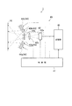
図1は、本発明の第1実施形態に係る情報コード読取システムを概念的に説明する説明図である。図1に示す情報コード読取システム1は、情報コードが表示される情報コード表示媒体10と、情報コード表示媒体10に付された情報コードを読み取る情報コード読取装置40とを備えたシステムとして構成されている。情報コード表示媒体10(以下、単に媒体10ともいう)は、明色モジュールCw及び暗色モジュールCbを有してなる第1情報コードC1、第2情報コードC2(図2、図3参照)が形成された媒体として構成されており、情報コード読取装置40(以下、単に読取装置40ともいう)は、この媒体10に形成された第1情報コードC1及び第2情報コード2を読取可能な装置として構成されている。そして、媒体10に形成された第1情報コードC1、第2情報コードC2を読取装置40が撮像し、解読することで、これらのコードに記録されたデータを取得し出力し得るようになっている。以下では、これら媒体10及び読取装置40について詳述する。
[First embodiment]
A first embodiment that embodies an information code reading system and the like according to the present invention will be described below with reference to the drawings.
(Outline of information code reading system)
FIG. 1 is an explanatory diagram conceptually illustrating an information code reading system according to a first embodiment of the present invention. The information code reading system 1 shown in FIG. 1 is configured as a system including an information
(情報コード表示媒体)
情報コード表示媒体10は、樹脂部材、ガラスなどの被形成部14に第1情報コードC1及び第2情報コードC2が形成されてなるものである。第1情報コードC1は、被形成部14の所定の第1面14A側に設けられ、複数種類のモジュールがマトリックス状に配列された構成となっている。具体的には、図3(A)に示すように、明色モジュール(明色セル)Cw及び暗色モジュール(暗色セル)Cbの2種類のセルによって構成されており、暗色モジュールCbは公知の赤外線透過インク(例えば、可視光照射時に透過性が相対的に低く、赤外光照射時に透過性が相対的に高いインク)が付された領域として構成されている。また、明色モジュールCwは、赤外線透過インクが付されず、後述する被形成部14の表面が露出し、被形成部14の表面が視認される領域として構成されている。また、明色モジュールと暗色モジュールが配列されたコード領域(暗色モジュールの配列領域を全て含む最小の矩形領域)の外側は、明色モジュールと同色のマージン領域によって囲まれており、このマージン領域も、赤外線透過インクが付されず、被形成部14の表面が視認される領域として構成されている。この第1情報コードC1は、例えば被形成部14の第1面14A上に赤外線透過インクを印刷する等の方法により形成することができる。
(Information code display medium)
The information
第2情報コードC2は、被形成部14において第1面14Aとは反対の第2面14B側に設けられており、複数種類のモジュールがマトリックス状に配列された構成となっている。具体的には、図3(B)に示すように、明色モジュール(明色セル)Cw及び暗色モジュール(暗色セル)Cbの2種類のセルによって構成されており、暗色モジュールCbは通常の暗色インク(赤外線照射時に透過しないインクであり、例えば黒色や藍色などの暗色のインク)が付された領域として構成されている。また、明色モジュールCwは、上記暗色インクが付されず、被形成部14の第2面14Bが露出し、第2面14B側から見て被形成部14が視認される領域として構成されている。第2情報コードC2において明色モジュールと暗色モジュールが配列されたコード領域(暗色モジュールの配列領域を全て含む最小の矩形領域)の外側は、明色モジュールと同色のマージン領域によって囲まれており、このマージン領域も、上記暗色インクが付されず、第2面14B側から見て被形成部14が視認される領域として構成されている。
The second information code C2 is provided on the
図3、図4等に示す例では、第1情報コードC1及び第2情報コードC2がいずれもQRコード(登録商標)として構成されており、公知の方法でデコード可能とされている。なお、第1情報コードC1及び第2情報コードC2の構成は多種の情報コードであってもよい。例えばバーコード等の公知の一次元コードであってもよく、データマトリックスコード、マキシコード等の公知の二次元コードなどによって構成されていてもよい。 In the example shown in FIG. 3, FIG. 4, etc., both the first information code C1 and the second information code C2 are configured as QR codes (registered trademark), and can be decoded by a known method. The configuration of the first information code C1 and the second information code C2 may be various information codes. For example, a known one-dimensional code such as a barcode may be used, or a known two-dimensional code such as a data matrix code or a maxi code may be used.
なお、図3等に示す例では、第1情報コードC1と第2情報コードC2とが同一種類のコードによって同一の外形サイズで構成され、第1情報コードC1の外形の真裏に第2情報コードC2の外形が重なるように構成されているが、第1情報コードC1と第2情報コードC2とが別の種類のコードによって構成されていてもよい。また、第1情報コードC1と第2情報コードC2とが異なるサイズで構成されていてもよい。 In the example shown in FIG. 3 and the like, the first information code C1 and the second information code C2 are configured by the same type of code and have the same outer size, and the second information code is directly behind the outer shape of the first information code C1. Although the outer shapes of C2 are configured to overlap, the first information code C1 and the second information code C2 may be configured by different types of codes. Further, the first information code C1 and the second information code C2 may be configured with different sizes.
被形成部14は、少なくとも可視光領域とは異なる第1波長帯の光が照射されたときに当該第1波長帯の光を透過する透過状態となり、可視光領域の第2波長帯の光が照射されたときに透過状態よりも透過性の低い状態となるものである。本構成では、例えばガラスや樹脂材料などからなる透明部材の表層部に赤外線透過インクを配置した構成、或いは被形成部14全体が赤外線透過インクと同様の材質とした構成などとされており、波長750nm以上の赤外光が「可視光領域とは異なる第1波長帯の光」に相当している。また、例えば、波長380nm〜750nmの可視光が「可視光領域の第2波長帯の光」に相当している。即ち、赤外光が照射されたときに当該赤外光を透過する透過状態となり、可視光が照射されたときにその透過状態(赤外光が照射されたときの透過状態)よりも透過性の低い状態となるように構成されている。なお、図3等に示す構成では、可視光が照射された可視光環境下で不透明状態となる被形成部14を用いている。
The formed
第1情報コードC1は、このような形成された被形成部14の第1面14A上において暗色モジュールの部分に、例えば公知の赤外線透過インクを配置した形態で形成されており、第2情報コードC2は、この被形成部14の第2面14B上において暗色モジュールの部分に、例えば通常の暗色インクを配置した形態で形成されている。なお、本構成では、第1面14Aを被形成部14の表面とし、第2面14Bを被形成部14の裏面としている。
The first information code C1 is formed in a form in which, for example, a known infrared transmitting ink is arranged on the dark color module portion on the
そして、図3(A)のように可視光が照射され、且つ赤外光が照射されていない又は赤外光の量が非常に少ない通常環境下(赤外光照射光源による照射がなされていない環境下)では被形成部14が不透明又は透明性の低い状態(赤外光照射時と比べて透明性が大幅に低い状態)となる。そして、表面側(第1面14A側)から見たときに被形成部14の裏側に位置する第2情報コードC2の形状が視認不能或いは視認困難となるように構成されている。なお、図3(A)では被形成部14の領域をクロスハッチングにて概念的に示し、第1情報コードC1の暗色モジュールの領域(第1情報コードC1において赤外線透過インクが付された領域)を黒色で示している。
Then, as shown in FIG. 3A, visible light is irradiated and infrared light is not irradiated or the amount of infrared light is very small (irradiation by an infrared light irradiation light source is not performed). Under the environment), the formed
第1面14A側から見たときの被形成部14の領域(クロスハッチングの領域)は、上記通常環境下(可視光が照射され、且つ赤外光が照射されていない又は赤外光の量が非常に少ない通常環境下)では第1情報コードC1の暗色モジュールの領域と、色彩、濃度、輝度の少なくともいずれかが異なるように構成されている。例えば、上記通常環境下では、第1情報コードC1の暗色モジュールの領域よりも、被形成部14の領域(クロスハッチングの領域)のほうが、明度が大きくなっている。第1情報コードC1の暗色モジュールの領域が黒色として認識され、被形成部14において第1情報コードC1の暗色モジュール以外の領域がグレーとして認識されるようになっている。
The region (cross-hatched region) of the
なお、図2等では、板状又はシート状の部材として構成される被形成部14に第1情報コードC1、第2情報コードC2が形成された例を示したが、被形成部14の構成や用途は様々である。例えば、商品の包装として構成されるビニール製の袋や樹脂製のケースなどであってもよく、ガラス製のケースなどであってもよい。或いは、被形成部14が商品やその他の物品そのものであってもよい。また、図2等の例では、被形成部14が一層で形成された例を示したが、「少なくとも可視光領域とは異なる第1波長帯の光が照射されたときに当該第1波長帯の光を透過する透過状態となり、可視光領域の第2波長帯の光が照射されたときに透過状態よりも透過性の低い状態となる構成」の層があれば、透明部材或いは透明性の高い部材などが重なった複数層として構成されていてもよい。
In FIG. 2 and the like, the example in which the first information code C1 and the second information code C2 are formed on the forming
被形成部14に形成された第1情報コードCは、反転領域と非反転領域とに分かれている。反転領域は、表面側(一方面14A側)から見て、可視光が照射されたときに暗色の反射特性を示し、可視光とは波長の異なる第1波長帯の光(例えば赤外光)が照射されたときに明色の反射特性を示すように構成されている。また、非反転領域は、可視光が照射されたときに明色の反射特性を示し、第1波長帯の光(例えば赤外光)が照射されたときにも明色の反射特性を示すように構成されている。そして、第1情報コードC1は、暗色モジュールCb(図3(A)に示す例では暗色セル)の領域が反転領域とされており、明色モジュールCw(図3(A)に示す例では明色セル)の領域が非反転領域となっている。また、コード領域(暗色モジュールCbが配置される領域を全て含む最小限の矩形領域)の周囲に隣接する領域も非反転領域となっている。即ち、コード領域のすぐ隣に隣接する環状のマージン領域も非反転領域として構成されている。
The first information code C formed in the
このように構成されているため、可視光(第2波長帯の光)が照射され第1波長帯の照明光(例えば赤外光)が照射されていない環境、又は第1波長帯の照明光(例えば赤外光)の光量が通常環境と同等に低い環境(特別な赤外光照射光源によって赤外光が照射されない環境)では、一般利用者が第1面14A側(表面側)から見たとき、図3(A)のように、第1情報コードC1では、明色モジュールCwの領域及びマージン領域を含む背景領域(コード領域の外側の領域)が明色で認識され、暗色モジュールCbの領域がこれら領域よりも明度の低い領域として認識されるため、それぞれが区別された状態で見えることになる。
Since it is configured in this manner, an environment in which visible light (second wavelength band light) is irradiated and illumination light in the first wavelength band (for example, infrared light) is not irradiated, or illumination light in the first wavelength band. In an environment where the amount of light (for example, infrared light) is as low as the normal environment (an environment in which infrared light is not irradiated by a special infrared light irradiation light source), a general user sees from the
また、第1情報コードC1の暗色モジュールCb及び明色モジュールCwは、可視光(第2波長帯の光)が照射されたときにそれぞれが可視光を反射し、これらモジュールが可視光を反射した反射光によって当該第1情報コードC1の像が生成されることになる。従って、通常の読取装置では、このような反射光を受光して撮像することで第1情報コードC1の形状が正確に示された画像を得ることができ、第1情報コードC1の認識、解読が可能となる。また、このように可視光(第2波長帯の光)が照射され第1波長帯の照明光(例えば赤外光)が照射されていない環境、又は第1波長帯の照明光(例えば赤外光)の光量が通常環境と同等に低い環境では、被形成部14は、不透明状態又は透明性の低い状態となるため、一般利用者が第1面14A側(表面側)から見たときには、裏側に位置する第2情報コードC2が把握不能或いは把握困難となる。そして、通常の読取装置では、第2情報コードC12の形状を第1面側から正確に認識することは困難になる。
The dark color module Cb and the light color module Cw of the first information code C1 each reflect visible light when irradiated with visible light (second wavelength band light), and these modules reflect visible light. The image of the first information code C1 is generated by the reflected light. Therefore, in a normal reading device, an image in which the shape of the first information code C1 is accurately shown can be obtained by receiving and imaging such reflected light, and the first information code C1 can be recognized and decoded. Is possible. In addition, an environment in which visible light (light in the second wavelength band) is irradiated and illumination light in the first wavelength band (for example, infrared light) is not irradiated, or illumination light in the first wavelength band (for example, infrared light) is used. In an environment where the amount of light) is as low as the normal environment, the
一方、媒体10の第1面14A側から赤外光(第1波長帯の光)が照射されている場合には、第1情報コードC1の明色モジュール及び暗色モジュールのいずれも、この赤外光(第1波長帯の光)を透過させ、更に、被形成部14もこの赤外光(第1波長帯の光)を透過させることになる。つまり、第2情報コードC2よりも表側(第1面14A側)に配された部分が透明性の高い状態になるため、図4のように、第1面14A側からでも第2情報コードC2を把握することができるようになる。そして、第2情報コードC2の複数種類のモジュールは、赤外光(第1波長帯の光)が照射されたときに少なくともいずれかの種類のモジュールが赤外光(第1波長帯の光)を反射するようになっており、このように赤外光(第1波長帯の光)を反射した反射光によって当該第2情報コードC2の像が生成されるようになっている。具体的には、通常の暗色インクが付された暗色モジュールCbの部分が赤外光を反射して暗色を示すようになっており、暗色インクが付されていない明色モジュールCwの部分及びマージン領域は、第2面14Bの後方(第1面14Aとは反対側)の背景状態を示すようになっている。
On the other hand, when infrared light (light in the first wavelength band) is irradiated from the
このように構成されているため、赤外光を照射しつつ撮像し得る後述の読取装置40を用いれば、第1面14A側から読み取る場合でも、このような反射光(赤外光を照射したときの第2情報コードC2からの反射光)を受光することで第2情報コードC2の形状が正確に示された画像を得ることができ、第2情報コードC2の認識、解読が可能となる。
Since it is configured in this way, even if reading is performed from the
本構成では、情報コード表示媒体10において、第1情報コードC1の暗色モジュールCbが第1のインクによって形成され、第2情報コードC2の暗色モジュールCbが第2のインクによって形成されている。また、第1情報コードC1及び第2情報コードC2の明色モジュールの領域には、いずれのインクも配されない構成となっている。
In this configuration, in the information
このうち、第1のインクは、第2波長帯の光(例えば可視光)が照射されたときに暗色(例えば黒色、藍色、青色等の暗色)の反射特性を示し、第1波長帯の光(例えば赤外光)が照射されたときに透明状態又は光透過性の高い明色状態となるように機能している。つまり、第1波長帯の光が照射されたときに暗色から明色(透明色又は光透過性の高い明色)に反転するようになっている。具体的には公知の赤外線反応インク(公知の赤外線透過インク等)として構成されており、波長750nm以上の赤外光が照射されたときに、ほぼ不可視状態又は透明性の高い明色状態となるように構成されている。 Of these, the first ink exhibits a reflection characteristic of a dark color (for example, a dark color such as black, indigo, and blue) when irradiated with light in the second wavelength band (for example, visible light), and has a first wavelength band. It functions so as to be in a transparent state or a light color state with high light transmittance when irradiated with light (for example, infrared light). That is, when light in the first wavelength band is irradiated, the color is inverted from a dark color to a light color (transparent color or light color with high light transmission). Specifically, it is configured as a known infrared reactive ink (such as a known infrared transmitting ink), and when it is irradiated with infrared light having a wavelength of 750 nm or more, it becomes a substantially invisible state or a highly transparent light color state. It is configured as follows.
また、第2のインクは、第2波長帯の光(例えば可視光)が照射されたときに暗色(例えば黒色、藍色、青色等の暗色)の反射特性を示し、第1波長帯の光(例えば赤外光)が照射されたときにも暗色(例えば黒色、藍色、青色等の暗色)の反射特性を示すように機能している。具体的には、通常のインク(赤外線によって反転しないインク)として構成されており、波長380nm〜750nmの可視光が照射されたときでも、波長750nm以上の赤外光が照射されたときでも、暗色(例えば黒色、藍色、青色等の暗色)を示すようになっている。 The second ink exhibits dark color (for example, dark color such as black, indigo, and blue) reflection characteristics when irradiated with light in the second wavelength band (for example, visible light), and light in the first wavelength band. Even when irradiated (for example, infrared light), it functions so as to exhibit reflection characteristics of dark colors (for example, dark colors such as black, indigo and blue). Specifically, it is configured as a normal ink (ink that is not inverted by infrared rays), and is dark when irradiated with visible light with a wavelength of 380 nm to 750 nm or with infrared light with a wavelength of 750 nm or more. (For example, dark colors such as black, indigo and blue).
なお、図3、図4の例では、第2情報コードC2の明色モジュールCwの領域及びマージン領域にインクを付しておらず、背景状態に少しでも明るさがあれば、赤外光を照射しつつ撮像したときに、図4のように、暗色モジュールCbと明色モジュールCwとが区別して撮像されることになるが、このような構成に限られない。例えば、第2情報コードC2の明色モジュールCwの領域及びマージン領域に通常の明色インク(赤外光を照射したときに白、黄色等として認識される明色のインクなど)を付してもよい。 In the example of FIGS. 3 and 4, no ink is applied to the area of the light color module Cw and the margin area of the second information code C2, and infrared light is used if there is even a little brightness in the background state. When imaging is performed while illuminating, as shown in FIG. 4, the dark color module Cb and the light color module Cw are distinguished and imaged, but the configuration is not limited thereto. For example, normal light ink (such as light ink recognized as white or yellow when irradiated with infrared light) is attached to the light color module Cw area and the margin area of the second information code C2. Also good.
(情報コード読取装置)
次に、情報コード読取装置40について説明する。
図1に示す情報コード読取装置40は、QRコード(登録商標)等の情報コードを撮像し、読み取る機能を有している。この読取装置40は、CPU等からなる制御部41、受光センサ(例えば、C−MOSエリアセンサ、CCDエリアセンサ等)を備えたカメラとして構成される撮像部42、可視光(第2波長帯の光)を照射する第2照明光源43、赤外光(第1波長帯の光)を照射する第1照明光源44、ROM、RAM、不揮発性メモリなどの記憶手段からなる記憶部45などを備えている。また、読取装置40には、液晶表示器などからなる表示部46や、各種操作キーなどからなる操作部47なども設けられている。なお、第1照明光源44は、「照射光源」の一例に相当し、赤外光(可視光領域とは異なる第1波長帯の光)を照射可能に構成されている。
(Information code reader)
Next, the information
The
撮像部42は、情報コードCを撮像可能に構成されたものであり、例えば一対の第2照明光源43a,43bの間に配置されている。この撮像部42は、情報コード表示媒体10からの反射光を受光センサ42aの受光面に結像させ、情報コード表示媒体10の画像データを生成するように機能している。具体的には、情報コード表示媒体10に対して第1照明光源44によって第1波長帯の光が照射されていない状態で第1情報コードC1の像を撮像し、情報コード表示媒体10に対して第1照明光源44によって第1波長帯の光が照射された状態で第2情報コードC2の像を撮像するように機能する。
The
受光センサ42aは、媒体10に照射されて反射した反射光を受光可能に構成されるもので、例えば、C−MOSやCCD等の固体撮像素子である受光素子を一次元に配列したラインセンサ、或いは2次元に配列したエリアセンサが、これに相当する。また、結像レンズ42cは、例えば、鏡筒とこの鏡筒内に収容される複数の集光レンズとによって構成されており、受光センサ42aの受光面に情報コードCのコード画像を結像するように機能している。光学系の受光センサ42aから出力される画像信号は、例えば記憶部45の画像データ蓄積領域に蓄積されるようになっている。
The
図1に示すように、照明光学系を構成する第2照明光源43及び第1照明光源44は、例えば撮像部42(受光光学系)を挟んだ両側にそれぞれ設けられている。一対の第2照明光源43a,43bは、例えば波長380nm〜750nmの可視光を照射するLEDによって構成されている。また、対をなして配置される第1照明光源44a,44bは、波長750nm以上の赤外光を照射する光源(LEDやその他の赤外線ランプ等)によって構成されている。なお、本構成では、第1照明光源44(第2照明光照射手段)の光源数が第2照明光源43(第1照明光照射手段)の光源数よりも多くなっている。
As shown in FIG. 1, the second
記憶部45は、例えばRAM(DRAM、SRAM等)、ROM(EPROM、EEPROM等)、その他の記憶デバイスがこれに相当する。この記憶部45のうちのRAMには、前述した画像データ蓄積領域のほかに、制御部41が算術演算や論理演算等の各処理時に利用する作業領域や読取条件テーブルも確保可能に構成されている。またROMには、各種処理等を実行可能な所定プログラムやその他、照明光源、受光センサ42a等の各ハードウェアを制御可能なシステムプログラム等が予め格納されている。
The
制御部41は、読取装置40全体を制御可能なマイコン等によって構成され、CPU、システムバス、入出力インタフェース等を備え、情報処理機能を有している。なお、本構成では、制御部41が解読部の一例に相当し、撮像部42によって第1情報コードC1が撮像された場合に当該第1情報コードC1を解読し、撮像部42によって第2情報コードC2が撮像された場合に当該第2情報コードC2を解読するように機能する。
The
具体的には、例えば赤外光を照射しないで撮像する第1モードと、赤外光を照射して撮像する第2モードとに切り替え可能とされている。第1モードでは、例えば第1照明光源44をオフ状態とし、第2照明光源43をオン状態として撮像部42による撮像を行う。このように第2照明光源43をオン状態にして第2波長帯の照明光(可視光)を照射しつつ撮像する場合、図2〜図4に示す媒体10が撮像範囲にあり、この媒体10の表面側から撮像したときには、図3(A)のように被形成部14が不透明状態或いは透明性の低い状態となり、2つのコードC1、C2の内、表面側(第1面14A側)に配置された第1情報コードC1のみの画像が得られる。従って、このような第1情報コードC1の画像を周知のデコード方法で解読することで、第1情報コードC1に記録されたデータを得ることが可能となる。
Specifically, for example, it is possible to switch between a first mode for imaging without irradiating infrared light and a second mode for imaging by irradiating infrared light. In the first mode, for example, the first
一方、第2モードでは、例えば第2照明光源43をオフ状態とし、第1照明光源44をオン状態として撮像部42による撮像を行う。このように第1照明光源44をオン状態にして第1波長帯の照明光(例えば赤外光)を照射しつつ撮像する場合、図2〜図4に示す媒体10が撮像範囲にあり、この媒体10の表面側(第1面14A側)から撮像したときには、図4のように第1情報コードC1及び被形成部14が透過状態となり、裏側(第2面14B側)に配置された第2情報コードC2の画像が得られる。従って、このような第2情報コードC2の画像を周知のデコード方法で解読することで、第2情報コードC2に記録されたデータを得ることが可能となる。
On the other hand, in the second mode, for example, the second
なお、これら第1モードと第2モードの切り替えは、自動的に行われてもよい。例えば、所定のトリガ操作を行った場合に、第1モードでの撮像を行い、その後、第2モードでの撮像を行うようにしてもよい。或いは、一定時間毎(例えば数ms毎、数秒毎)に、第1モードでの撮像と、第2モードでの撮像を切り換えるようにしてもよい。或いは、所定のトリガ操作の後に第1モードでの撮像を行い、第1情報コードC1の解読を試み、第1情報コードC1の解読が成功した場合に、第2モードでの撮像を行い、第2情報コードC2の解読を試みてもよい。 The switching between the first mode and the second mode may be performed automatically. For example, when a predetermined trigger operation is performed, imaging in the first mode may be performed, and then imaging in the second mode may be performed. Alternatively, the imaging in the first mode and the imaging in the second mode may be switched at regular time intervals (for example, every few ms or every few seconds). Alternatively, imaging in the first mode is performed after a predetermined trigger operation, the first information code C1 is attempted to be decoded, and if the decoding of the first information code C1 is successful, imaging in the second mode is performed, It is possible to try to decode the two information code C2.
或いは、これら第1モードと第2モードの切り替えは、ユーザによって所定操作がなされたときに切り替わるようにしてもよい。例えば、ユーザが所定の第1操作(所定ボタンに対する第1の操作等)を行ったときに、第1モードでの撮像を行い、所定の第2操作(所定ボタンに対する第2の操作等)を行ったときに、第2モードでの撮像を行うようにしてもよい。 Alternatively, the switching between the first mode and the second mode may be switched when a predetermined operation is performed by the user. For example, when the user performs a predetermined first operation (first operation on a predetermined button, etc.), imaging in the first mode is performed, and a predetermined second operation (second operation on the predetermined button, etc.) is performed. When this is done, imaging in the second mode may be performed.
なお、図3、図4等に示す代表例では、第1情報コードC1、第2情報コードC2がいずれもQRコード(登録商標)である場合を例示したが、データマトリックスコードやマキシコードなど、明色モジュールと暗色モジュールによって表現される他種の二次元コードでも同様に適用でき、明色モジュールと暗色モジュールによって表現されるコードであれば、一次元バーコードなどの一次元コードでも同様に適用できる。 In the representative examples shown in FIGS. 3 and 4, the first information code C <b> 1 and the second information code C <b> 2 are both QR codes (registered trademark), but a data matrix code, a maxi code, etc. The same applies to other types of two-dimensional codes expressed by light and dark color modules, as well as one-dimensional barcodes such as one-dimensional barcodes as long as the codes are expressed by light and dark color modules. it can.
本構成では、情報コード表示媒体10は、少なくとも可視光領域とは異なる第1波長帯の光が照射されたときに当該第1波長帯の光を透過する透過状態となり、可視光領域の第2波長帯の光が照射されたときに透過状態よりも透過性の低い状態となる被形成部14と、被形成部14の所定の第1面14A側に設けられ、複数種類のモジュールを備えてなる第1情報コードC1と、被形成部14の第1面14Aとは反対の第2面14B側に設けられ、複数種類のモジュールを備えてなる第2情報コードC2とを有している。
そして、第1情報コードC1の複数種類のモジュールは、第1波長帯の光が照射されたときにこの第1波長帯の光を透過し、可視光が照射されたときに少なくともいずれかの種類のモジュールが可視光を反射すると共に当該可視光を反射した反射光によって当該第1情報コードC1の像が生成される構成となっている。この構成では、可視光が照射され、第1波長帯の光が照射されない又は第1波長帯の光の量が少ない環境下では、被形成部14が透過性の低い状態となる。つまり、第1面14A側から見たときに、第1情報コードC1は視認可能となるが、第2情報コードC2の視認は困難となる。また、第1波長帯の光を照射しない通常の読み取り装置では、第1面14A側から読み取る場合、被形成部14の透過性が低く奥側の第2情報コードC2が認識困難な状態で読み取ることになるため、これら2つのコードの内、第1情報コードC1のみを読み取ることができる。
一方、第1波長帯の光が照射された場合、被形成部14は、第1波長帯の光を透過する透過状態となり、第2情報コードC2は、いずれかの種類のモジュールが第1波長帯の光を反射すると共にこの第1波長帯の光を反射した反射光によって当該第2情報コードC2の像が生成される。従って、第1波長帯の光を照射可能な読取装置では、第1波長帯の光を照射しつつ撮像することで、第1面14A側からでも第2情報コードC2を読み取ることができる。
In this configuration, the information
The plurality of types of modules of the first information code C1 transmit light in the first wavelength band when irradiated with light in the first wavelength band, and at least any type when irradiated with visible light. This module is configured to reflect the visible light and generate an image of the first information code C1 by the reflected light reflecting the visible light. In this configuration, under the environment where visible light is irradiated and light in the first wavelength band is not irradiated or the amount of light in the first wavelength band is small, the portion to be formed 14 is in a state of low transparency. That is, when viewed from the
On the other hand, when the light of the first wavelength band is irradiated, the
また、第2情報コードC2が被形成部14の厚さ方向において第1情報コードC1の少なくとも一部と重なる構成で配置されている。この構成では、仮に可視光環境下において被形成部14で若干の透過状態が生じた場合でも、第1面14A側から見た場合に第2情報コードC2の少なくとも一部が第1情報コードC1の裏側に隠れる構成となる。つまり、第2情報コードC2の正確な形状の把握がより困難になるため、可視光環境下における一般的な読取装置での第2情報コードC2の読み取りをより確実に防ぐことができる。
Further, the second information code C2 is arranged so as to overlap with at least a part of the first information code C1 in the thickness direction of the
なお、第2情報コードC2には、少なくとも第1情報コードC1に記録されていないデータが記録されていてもよい。この構成によれば、特定の読取装置での読み取りが望まれ、一般的な読取装置での読み取りが望まれないデータを扱う場合に非常に有利になる。例えば、被形成部14がある商品の一部又は包装として構成される場合、表側(第1面14A側)の第1情報コードC1には、ユーザに提供すべき情報(例えば、商品に関する情報(材料、原産地、効能、その他の広告情報など)や、商品提供企業のインターネット上のアドレス等)を記録しておき、第2情報コードC2には、正規品であるか否かを判別するための識別情報(例えば正規品であることを示すシリアル番号等)などを記録するといった使用方法が可能である。このようにすれば、第2情報コードC2の存在自体を分かりにくくすることができ、特定の読取装置に限って正規品チェックをすることが可能となる。
Note that at least data that is not recorded in the first information code C1 may be recorded in the second information code C2. According to this configuration, reading with a specific reading device is desired, which is very advantageous when data that is not desired to be read with a general reading device is handled. For example, when the formed
[第2実施形態]
次に第2実施形態について図5を参照しつつ説明する。
第2実施形態は、第1実施形態の構成をすべて含み、更に、接着層16が付加された構成となっている。この第2実施形態に係る情報コード読取システム1は、情報コード表示媒体10に接着層16が設けられている点のみが第1実施形態と異なり、それ以外は第1実施形態と同一である。よって、第1実施形態と同一の構成については第1実施形態と同一の符号を付し、詳細な説明は省略する。特に、情報コード読取装置40の構成は第1実施形態と同一である。また、媒体10は、接着層16以外は第1実施形態と同一である。
[Second Embodiment]
Next, a second embodiment will be described with reference to FIG.
The second embodiment includes all the configurations of the first embodiment, and further has a configuration in which an
本構成に係る情報コード表示媒体10も、図5に示すように、少なくとも可視光領域とは異なる第1波長帯の光が照射されたときに当該第1波長帯の光を透過する透過状態となり、可視光領域の第2波長帯の光が照射されたときに前記透過状態よりも透過性の低い状態となる被形成部14を備えている。そして、被形成部14の所定の第1面14A側に設けられ、複数種類のモジュールを備えてなる第1情報コードC1と、被形成部14における第1面14Aとは反対の第2面14B側に設けられ、複数種類のモジュールを備えてなる第2情報コードC2とを備えている。なお、被形成部14、第1情報コードC1、第2情報コードC2の構成は第1実施形態と同一であり、第1実施形態で説明した変形例と同様の変形構造が可能である。
As shown in FIG. 5, the information
更に本構成では、被形成部14における裏面側(即ち、第2面14B側)に接着媒体による接着層16が設けられている。この接着層16は、ある程度の粘度を有する公知の接着剤などによって構成されていてもよく、公知の両面テープなどの接着シートによって構成されていてもよい。接着層16が接着シートによって構成されている場合、接着層16は、シート状に構成され、第2面14B側の面が接着性を有するとともに、第2面14B側とは反対側の面(図5の例では露出する面)も接着性を有する。そして、この場合、接着層16における被形成部14側の面が第2面14Bに接着し、接着層16における被形成部14とは反対側の面が他の物体に接着するように用いられる。なお、この情報コード表示媒体10を接着する対象物体は様々であり、様々な商品であってもよく、様々な機器、設備、用具などであってもよい。また、ガラス製品や貴金属製品など、直接の印刷が困難或いは直接の印刷が望まれない物品に貼り付けて用いると有用である。
Further, in this configuration, an
本構成でも、被形成部14は、第1実施形態と同様の構成であり、撓み変形可能な板材又はシート材等として構成されている。そして、被形成部14の厚さ方向他方側の面(第2面14B)を覆う構成で接着層16が設けられている。なお、本構成では、接着層16以外の部分の機能、効果は第1実施形態と同様である。例えば、通常時に表面側から見た構成は図3(A)と同様であり、赤外光を照射せず可視光を照射した状態での撮像画像(例えば、読取装置40による上記第1モードでの撮像画像)も図3(A)と同様であり、このような画像を読取装置40によって撮像することで第1情報コードC1を解読することが可能となる。一方、上述の読取装置40により赤外光(第1波長帯の光)を照射しつつ撮像部42によって撮像したときの画像(例えば、読取装置40による上記第2モードでの撮像画像)は図4と同様であり、このような画像を読取装置40によって撮像することで第2情報コードC2を解読することが可能となる。
Also in this configuration, the formed
本構成でも、第1実施形態と同様の効果が得られる。更に、被形成部14における第2面14B側に接着媒体による接着層16が設けられているため、情報コード表示媒体10の全体をシールとして利用することができ、当該情報コード表示媒体10が接着された部分において上記発明と同様の効果を生じさせることができる。これにより、例えば2種類の情報コードC1、C2を直接形成しにくい対象物において上記利益を享受したい場合や、対象物形成後に事後的に上記特徴を付加したい場合などにおいて有利になる。
Even in this configuration, the same effect as in the first embodiment can be obtained. Furthermore, since the
また、被形成部14は、撓み変形可能な板材又はシート材として構成されている。この構成によれば、情報コード表示媒体10の適用位置の自由度が増し、例えば平坦部分は勿論のこと、ある程度湾曲した部分や若干凹凸がある部分などに対しても特徴的な情報コード表示媒体10を付すことができる。
Moreover, the to-
[他の実施形態]
本発明は上記記述及び図面によって説明した実施形態に限定されるものではなく、例えば次のような実施形態も本発明の技術的範囲に含まれる。
[Other Embodiments]
The present invention is not limited to the embodiments described with reference to the above description and drawings. For example, the following embodiments are also included in the technical scope of the present invention.
上記実施形態では、第2情報コードC2は、被形成部14の第2面14B上に形成された構成を示したが、第1情報コードC1よりも第2面14B寄りであれば、第2面14B上でなくてもよい。例えば、被形成部14の内部に形成されていてもよい。
In the above embodiment, the second information code C2 is configured to be formed on the
上記実施形態では、第1波長帯の光として赤外光を例示したが、第1波長帯は、可視光領域以外の他の波長帯の光であってもよい。この場合、被形成部や第1情報コードC1の暗色モジュールは、第1波長帯の光を当てた時に透過性の高い状態となり、可視光を当てた時に透過性の低い状態となる材料によって構成すればよい。 In the above embodiment, infrared light is exemplified as the light in the first wavelength band, but the first wavelength band may be light in a wavelength band other than the visible light region. In this case, the dark color module of the part to be formed and the first information code C1 is made of a material that is in a highly transmissive state when irradiated with light in the first wavelength band and is in a low transmissive state when exposed to visible light. do it.
上記実施形態では、第1情報コードC1の真裏に第2情報コードC2が配置される構成を例示したが、第1情報コードC1と第2情報コードC2の外形が完全に重ならず、一部のみが前後(被形成部14の厚さ方向)に重なるように構成されていてもよい。或いは、第1情報コードC1と第2情報コードC2とが前後に重ならないように配置されていてもよい。 In the above-described embodiment, the configuration in which the second information code C2 is arranged directly behind the first information code C1 is exemplified. However, the outer shapes of the first information code C1 and the second information code C2 are not completely overlapped and are partially Only the front and rear (in the thickness direction of the portion to be formed 14) may be configured to overlap. Alternatively, the first information code C1 and the second information code C2 may be arranged so as not to overlap each other.
上記実施形態では、第1面14A側に1つの第1情報コードC1が形成された例を示したが、第1面14A側に複数の第1情報コードC1が形成されていてもよい。或いは、第2面14B側に複数の第2情報コードC2が形成されていてもよい。
In the above embodiment, an example in which one first information code C1 is formed on the
1…情報コード読取システム
10…情報コード表示媒体
14…被形成部
14A…第1面
14B…第2面
16…接着層
40…情報コード読取装置
41…制御部(解読部)
42…撮像部
44…第1照明光源(照明光源)
C1…第1情報コード
C2…第2情報コード
DESCRIPTION OF SYMBOLS 1 ... Information
42 ...
C1 ... 1st information code C2 ... 2nd information code
Claims (7)
前記被形成部の所定の第1面側に設けられ、暗色モジュールと前記被形成部の第1面側を露出させることで構成される明色モジュールとを備えてなる第1情報コードと、
前記被形成部の前記第1面とは反対の第2面側に設けられ、暗色モジュールと前記被形成部の第2面側を露出させることで構成される明色モジュールとを備えてなる第2情報コードと、
を有し、
前記第1情報コードの前記暗色モジュールは、前記第1波長帯の光が照射されたときに前記第1波長帯の光を透過し、前記第2波長帯の光が照射されたときに前記第2波長帯の光を反射すると共に当該第2波長帯の光を反射した反射光によって当該第1情報コードの像が生成される構成であり、
前記第2情報コードの前記暗色モジュールは、前記第1波長帯の光が照射されたときに前記第1波長帯の光を反射すると共に前記第1波長帯の光を反射した反射光によって当該第2情報コードの像が生成される構成であり、
前記第2情報コードは、前記被形成部の前記第2面側に対して前記第1面側から見て前記第1情報コードの少なくとも一部と重なる構成で配置され、
前記第2情報コードには、少なくとも前記第1情報コードに記録されていないデータが記録されていることを特徴とする情報コード表示媒体。 When the light of the first wavelength band different from at least the visible light region is irradiated, the light is transmitted through the first wavelength band, and the light of the second wavelength band of the visible light region is irradiated. A forming part that is in a state of lower permeability than the transmission state;
A first information code provided on a predetermined first surface side of the formed portion, and comprising a dark color module and a light color module configured by exposing the first surface side of the formed portion;
A second module is provided on the second surface side opposite to the first surface of the formed portion, and includes a dark color module and a light color module configured by exposing the second surface side of the formed portion. Two information codes;
Have
The dark color module of the first information code transmits the light of the first wavelength band when irradiated with the light of the first wavelength band, and the first module when the light of the second wavelength band is irradiated. An image of the first information code is generated by reflected light that reflects light in the second wavelength band and reflects light in the second wavelength band,
The dark color module of the second information code reflects the first wavelength band light when irradiated with the first wavelength band light and reflects the first wavelength band light by the reflected light. 2 An image of an information code is generated,
The second information code is arranged in a configuration overlapping with at least a part of the first information code when viewed from the first surface side with respect to the second surface side of the formed portion ,
The information code display medium , wherein at least data not recorded in the first information code is recorded in the second information code .
前記被形成部の所定の第1面側に設けられ、暗色モジュールと前記被形成部の第1面側を露出させることで構成される明色モジュールとを備えてなる第1情報コードと、
前記被形成部の前記第1面とは反対の第2面側に設けられ、暗色モジュールと前記被形成部の第2面側を露出させることで構成される明色モジュールとを備えてなる第2情報コードと、
を有し、
前記第1情報コードの前記暗色モジュールは、前記第1波長帯の光が照射されたときに前記第1波長帯の光を透過し、可視光領域の第2波長帯の光が照射されたときに前記第2波長帯の光を反射すると共に当該第2波長帯の光を反射した反射光によって当該第1情報コードの像が生成される構成であり、
前記第2情報コードの前記暗色モジュールは、前記第1波長帯の光が照射されたときに前記第1波長帯の光を反射すると共に前記第1波長帯の光を反射した反射光によって当該第2情報コードの像が生成される構成であり、
前記第2情報コードは、前記被形成部の前記第2面側に対して前記第1面側から見て前記第1情報コードの少なくとも一部と重なる構成で配置され、
前記第2情報コードには、少なくとも前記第1情報コードに記録されていないデータが記録されていることを特徴とする情報コード表示媒体。 A formation part that is in a transmission state that transmits light of the first wavelength band when irradiated with light of a first wavelength band different from at least the visible light region;
A first information code provided on a predetermined first surface side of the formed portion, and comprising a dark color module and a light color module configured by exposing the first surface side of the formed portion;
A second module is provided on the second surface side opposite to the first surface of the formed portion, and includes a dark color module and a light color module configured by exposing the second surface side of the formed portion. Two information codes;
Have
The dark color module of the first information code transmits light in the first wavelength band when irradiated with light in the first wavelength band, and is irradiated with light in the second wavelength band in the visible light region. The image of the first information code is generated by the reflected light that reflects the light in the second wavelength band and reflects the light in the second wavelength band.
The dark color module of the second information code reflects the first wavelength band light when irradiated with the first wavelength band light and reflects the first wavelength band light by the reflected light. 2 An image of an information code is generated,
The second information code is arranged in a configuration overlapping with at least a part of the first information code when viewed from the first surface side with respect to the second surface side of the formed portion ,
The information code display medium , wherein at least data not recorded in the first information code is recorded in the second information code .
前記情報コード表示媒体は、The information code display medium is
少なくとも可視光領域とは異なる第1波長帯の光が照射されたときに当該第1波長帯の光を透過する透過状態となり、可視光領域の第2波長帯の光が照射されたときに前記透過状態よりも透過性の低い状態となる被形成部と、When the light of the first wavelength band different from at least the visible light region is irradiated, the light is transmitted through the first wavelength band, and the light of the second wavelength band of the visible light region is irradiated. A forming part that is in a state of lower permeability than the transmission state;
前記被形成部の所定の第1面側に設けられ、暗色モジュールと前記被形成部の第1面側を露出させることで構成される明色モジュールとを備えてなる第1情報コードと、A first information code provided on a predetermined first surface side of the formed portion, and comprising a dark color module and a light color module configured by exposing the first surface side of the formed portion;
前記被形成部の前記第1面とは反対の第2面側に設けられ、暗色モジュールと前記被形成部の第2面側を露出させることで構成される明色モジュールとを備えてなる第2情報コードと、A second module is provided on the second surface side opposite to the first surface of the formed portion, and includes a dark color module and a light color module configured by exposing the second surface side of the formed portion. Two information codes;
を有し、Have
前記第1情報コードの前記暗色モジュールは、前記第1波長帯の光が照射されたときに前記第1波長帯の光を透過し、前記第2波長帯の光が照射されたときに前記第2波長帯の光を反射すると共に当該第2波長帯の光を反射した反射光によって当該第1情報コードの像が生成される構成であり、The dark color module of the first information code transmits the light of the first wavelength band when irradiated with the light of the first wavelength band, and the first module when the light of the second wavelength band is irradiated. An image of the first information code is generated by reflected light that reflects light in the second wavelength band and reflects light in the second wavelength band,
前記第2情報コードの前記暗色モジュールは、前記第1波長帯の光が照射されたときに前記第1波長帯の光を反射すると共に前記第1波長帯の光を反射した反射光によって当該第2情報コードの像が生成される構成であり、The dark color module of the second information code reflects the first wavelength band light when irradiated with the first wavelength band light and reflects the first wavelength band light by the reflected light. 2 An image of an information code is generated,
前記第2情報コードは、前記被形成部の前記第2面側に対して前記第1面側から見て前記第1情報コードの少なくとも一部と重なる構成で配置されており、The second information code is arranged in a configuration overlapping with at least a part of the first information code when viewed from the first surface side with respect to the second surface side of the formed part,
前記第2情報コードには、少なくとも前記第1情報コードに記録されていないデータが記録され、In the second information code, at least data not recorded in the first information code is recorded,
前記情報コード読取装置は、The information code reader is
前記第1波長帯の光を照射可能な照射光源と、An irradiation light source capable of emitting light in the first wavelength band;
前記情報コード表示媒体に対して前記照射光源によって前記第1波長帯の光が照射されていない状態で前記第1情報コードの像を撮像し、前記情報コード表示媒体に対して前記照射光源によって前記第1波長帯の光が照射された状態で前記第2情報コードの像を撮像する撮像部と、An image of the first information code is captured in a state where the light source of the first wavelength band is not irradiated to the information code display medium by the irradiation light source, and the information code display medium is input to the information code display medium by the irradiation light source. An imaging unit that captures an image of the second information code in a state of being irradiated with light in the first wavelength band;
前記撮像部によって前記第1情報コードが撮像された場合に当該第1情報コードを解読し、前記撮像部によって前記第2情報コードが撮像された場合に当該第2情報コードを解読する解読部と、A decoding unit that decodes the first information code when the first information code is imaged by the imaging unit, and that decodes the second information code when the second information code is imaged by the imaging unit; ,
を有することを特徴とする情報コード読取システム。An information code reading system comprising:
前記情報コード表示媒体は、
少なくとも可視光領域とは異なる第1波長帯の光が照射されたときに当該第1波長帯の光を透過する透過状態となる被形成部と、
前記被形成部の所定の第1面側に設けられ、暗色モジュールと前記被形成部の第1面側を露出させることで構成される明色モジュールとを備えてなる第1情報コードと、
前記被形成部の前記第1面とは反対の第2面側に設けられ、暗色モジュールと前記被形成部の第2面側を露出させることで構成される明色モジュールとを備えてなる第2情報コードと、
を有し、
前記第1情報コードの前記暗色モジュールは、前記第1波長帯の光が照射されたときに前記第1波長帯の光を透過し、可視光領域の第2波長帯の光が照射されたときに前記第2波長帯の光を反射すると共に当該第2波長帯の光を反射した反射光によって当該第1情報コードの像が生成される構成であり、
前記第2情報コードの前記暗色モジュールは、前記第1波長帯の光が照射されたときに前記第1波長帯の光を反射すると共に前記第1波長帯の光を反射した反射光によって当該第2情報コードの像が生成される構成であり、
前記第2情報コードは、前記被形成部の前記第2面側に対して前記第1面側から見て前記第1情報コードの少なくとも一部と重なる構成で配置されており、
前記第2情報コードには、少なくとも前記第1情報コードに記録されていないデータが記録され、
前記情報コード読取装置は、
前記第1波長帯の光を照射可能な照射光源と、
前記情報コード表示媒体に対して前記照射光源によって前記第1波長帯の光が照射されていない状態で前記第1情報コードの像を撮像し、前記情報コード表示媒体に対して前記照射光源によって前記第1波長帯の光が照射された状態で前記第2情報コードの像を撮像する撮像部と、
前記撮像部によって前記第1情報コードが撮像された場合に当該第1情報コードを解読し、前記撮像部によって前記第2情報コードが撮像された場合に当該第2情報コードを解読する解読部と、
を有することを特徴とする情報コード読取システム。 An information code reading system comprising: an information code display medium on which an information code is displayed; and an information code reading device that reads the information code attached to the information code display medium,
The information code display medium is
And forming portion of light of different first wavelength band is transmission state for transmitting light of the first wavelength band when it is irradiated with at least a visible light region,
A first information code provided on a predetermined first surface side of the formed portion, and comprising a dark color module and a light color module configured by exposing the first surface side of the formed portion;
A second module is provided on the second surface side opposite to the first surface of the formed portion, and includes a dark color module and a light color module configured by exposing the second surface side of the formed portion. Two information codes;
Have
The dark color module of the first information code transmits light in the first wavelength band when irradiated with light in the first wavelength band, and is irradiated with light in the second wavelength band in the visible light region . The image of the first information code is generated by the reflected light that reflects the light in the second wavelength band and reflects the light in the second wavelength band.
The dark color module of the second information code reflects the first wavelength band light when irradiated with the first wavelength band light and reflects the first wavelength band light by the reflected light. 2 An image of an information code is generated,
The second information code is arranged in a configuration overlapping with at least a part of the first information code when viewed from the first surface side with respect to the second surface side of the formed part,
In the second information code, at least data not recorded in the first information code is recorded,
The information code reader is
An irradiation light source capable of emitting light in the first wavelength band;
An image of the first information code is captured in a state where the light source of the first wavelength band is not irradiated to the information code display medium by the irradiation light source, and the information code display medium is input to the information code display medium by the irradiation light source. An imaging unit that captures an image of the second information code in a state of being irradiated with light in the first wavelength band;
A decoding unit that decodes the first information code when the first information code is imaged by the imaging unit, and that decodes the second information code when the second information code is imaged by the imaging unit; ,
An information code reading system comprising:
Priority Applications (1)
| Application Number | Priority Date | Filing Date | Title |
|---|---|---|---|
| JP2013115249A JP6285111B2 (en) | 2013-05-31 | 2013-05-31 | Information code display medium and information code reading system |
Applications Claiming Priority (1)
| Application Number | Priority Date | Filing Date | Title |
|---|---|---|---|
| JP2013115249A JP6285111B2 (en) | 2013-05-31 | 2013-05-31 | Information code display medium and information code reading system |
Publications (2)
| Publication Number | Publication Date |
|---|---|
| JP2014235488A JP2014235488A (en) | 2014-12-15 |
| JP6285111B2 true JP6285111B2 (en) | 2018-02-28 |
Family
ID=52138173
Family Applications (1)
| Application Number | Title | Priority Date | Filing Date |
|---|---|---|---|
| JP2013115249A Active JP6285111B2 (en) | 2013-05-31 | 2013-05-31 | Information code display medium and information code reading system |
Country Status (1)
| Country | Link |
|---|---|
| JP (1) | JP6285111B2 (en) |
Families Citing this family (3)
| Publication number | Priority date | Publication date | Assignee | Title |
|---|---|---|---|---|
| JP6486813B2 (en) * | 2015-10-30 | 2019-03-20 | 東芝インフラシステムズ株式会社 | Code reader |
| WO2017073780A1 (en) * | 2015-10-30 | 2017-05-04 | 株式会社 東芝 | Apparatus for reading information code and method of generating information code |
| JP6502882B2 (en) * | 2016-03-14 | 2019-04-17 | 東芝インフラシステムズ株式会社 | INFORMATION CODE READER, INFORMATION CODE GENERATION METHOD, AND INFORMATION CODE DISPLAY MEDIUM |
Family Cites Families (7)
| Publication number | Priority date | Publication date | Assignee | Title |
|---|---|---|---|---|
| JPH06247084A (en) * | 1993-02-24 | 1994-09-06 | Dainippon Printing Co Ltd | Diffraction pattern recording medium and method of authenticating the same |
| JP3358231B2 (en) * | 1993-04-06 | 2002-12-16 | 凸版印刷株式会社 | Information carrier and information reproducing apparatus handling the same |
| JP2741568B2 (en) * | 1993-06-30 | 1998-04-22 | 株式会社田村電機製作所 | Card judgment method |
| US6119943A (en) * | 1994-12-12 | 2000-09-19 | Moore Business Forms, Inc. | Multi-layer bar code arrangement using wavelength separation |
| JPH11180079A (en) * | 1997-12-25 | 1999-07-06 | Dainippon Printing Co Ltd | Information recording medium and its certificating system |
| JP2001160121A (en) * | 1999-09-24 | 2001-06-12 | Sanyo Electric Co Ltd | Medium and method for recording information, and system and method for reading information |
| US7264169B2 (en) * | 2004-08-02 | 2007-09-04 | Idx, Inc. | Coaligned bar codes and validation means |
-
2013
- 2013-05-31 JP JP2013115249A patent/JP6285111B2/en active Active
Also Published As
| Publication number | Publication date |
|---|---|
| JP2014235488A (en) | 2014-12-15 |
Similar Documents
| Publication | Publication Date | Title |
|---|---|---|
| JP6927559B2 (en) | Optical code, optical code creation method, optical code authenticity determination method, optical code reader, and reading aid | |
| US9562998B2 (en) | Inconspicuous optical tags and methods therefor | |
| EP2713306B1 (en) | Information code medium, and system and apparatus for reading information code provided by the same | |
| US7370798B2 (en) | Coaligned bar codes and validation means | |
| JP6347295B2 (en) | Information code and information code reader | |
| US9129198B2 (en) | Information code and information code reader | |
| KR101923503B1 (en) | Security Film Using Coded Patterns and Detection Apparatus thereof | |
| WO2010095545A1 (en) | Printing medium, method for appraising authenticity of printing medium, and image processing inspection system appropriate for printing medium | |
| JP2004206674A (en) | Two-dimensional code and formation structure thereof | |
| JP6128749B2 (en) | Optical reader, optical reading method and program | |
| JP6285111B2 (en) | Information code display medium and information code reading system | |
| EP2835761A1 (en) | Film on which code is recorded, reader used for recognizing the film on which code is recorded, and electronic apparatus including display device having film on which code is recorded attached thereto | |
| JP5850411B2 (en) | Information code | |
| JP6136521B2 (en) | Information code display medium and information code reading system | |
| WO2017104856A1 (en) | Optical code, optical code creation method, optical code authenticity determination method, optical code reading device and reading assistance device | |
| JP2015060270A (en) | Determination system, determination device, and print medium | |
| JP7113642B2 (en) | Information code and information code reader | |
| JP5724774B2 (en) | Information code reading system and information code reading device | |
| JP2006213017A (en) | Infrared absorption printed matter and its reading method | |
| JP4736788B2 (en) | Container with optical information, method for reading optical information | |
| JP2014071466A (en) | Information code read system and information code reader | |
| KR101330029B1 (en) | A Film Recorded with Code, Electronic Device Equipped with Display Covered with the Film | |
| JP2014071465A (en) | Information code read system, information code reader, and information code display body | |
| US20210390276A1 (en) | Information code reader | |
| JP2020161108A (en) | Information code reader |
Legal Events
| Date | Code | Title | Description |
|---|---|---|---|
| A621 | Written request for application examination |
Free format text: JAPANESE INTERMEDIATE CODE: A621 Effective date: 20160204 |
|
| A977 | Report on retrieval |
Free format text: JAPANESE INTERMEDIATE CODE: A971007 Effective date: 20161122 |
|
| A131 | Notification of reasons for refusal |
Free format text: JAPANESE INTERMEDIATE CODE: A131 Effective date: 20161220 |
|
| A521 | Request for written amendment filed |
Free format text: JAPANESE INTERMEDIATE CODE: A523 Effective date: 20170220 |
|
| A131 | Notification of reasons for refusal |
Free format text: JAPANESE INTERMEDIATE CODE: A131 Effective date: 20170310 |
|
| A521 | Request for written amendment filed |
Free format text: JAPANESE INTERMEDIATE CODE: A523 Effective date: 20170508 |
|
| A02 | Decision of refusal |
Free format text: JAPANESE INTERMEDIATE CODE: A02 Effective date: 20170530 |
|
| A521 | Request for written amendment filed |
Free format text: JAPANESE INTERMEDIATE CODE: A523 Effective date: 20170829 |
|
| A911 | Transfer to examiner for re-examination before appeal (zenchi) |
Free format text: JAPANESE INTERMEDIATE CODE: A911 Effective date: 20170906 |
|
| A912 | Re-examination (zenchi) completed and case transferred to appeal board |
Free format text: JAPANESE INTERMEDIATE CODE: A912 Effective date: 20171006 |
|
| A61 | First payment of annual fees (during grant procedure) |
Free format text: JAPANESE INTERMEDIATE CODE: A61 Effective date: 20180201 |
|
| R150 | Certificate of patent or registration of utility model |
Ref document number: 6285111 Country of ref document: JP Free format text: JAPANESE INTERMEDIATE CODE: R150 |
|
| R250 | Receipt of annual fees |
Free format text: JAPANESE INTERMEDIATE CODE: R250 |
|
| R250 | Receipt of annual fees |
Free format text: JAPANESE INTERMEDIATE CODE: R250 |
|
| R250 | Receipt of annual fees |
Free format text: JAPANESE INTERMEDIATE CODE: R250 |
|
| R250 | Receipt of annual fees |
Free format text: JAPANESE INTERMEDIATE CODE: R250 |