特許文献1の電気かみそりによれば、ローラーの周速度を内刃の周速度より小さく設定することにより、ローラーによる肌面への負担を軽減しながらひげを起毛して、ひげ切断後の肌面のヒリ付きを抑止できる。しかし、ひげ切断を開始してからひげ切断が終了するまでの間、ローラーは切断刃と共に回転駆動されて肌面を伸ばし、連続して肌面を擦り続ける。そのため、ローラーによる肌面に対する負担が大きく、ひげ切断後の肌面にヒリ付きが生じるのを避けられない。
According to the electric razor of Patent Document 1, by setting the peripheral speed of the roller smaller than the peripheral speed of the inner blade, the beard is raised while reducing the burden on the skin surface by the roller, and the skin surface after cutting the beard Can be suppressed. However, from the start of beard cutting to the end of beard cutting, the roller is rotationally driven together with the cutting blade to stretch the skin surface and continuously rub the skin surface. For this reason, the burden on the skin surface by the roller is large, and it is inevitable that the skin surface after cutting the beard is bruised.
本発明者は、特許文献1の肌面伸張構造に関して、肌面を伸張操作してひげを起毛する際の肌面のヒリ付きを軽減することを検討した。また、検討過程では肌面伸張構造の構造および動作の最適化と、肌面伸張構造と切断刃の好適な配置形態、およびモータの駆動負荷の軽減などを再検討し、その結果、本発明の電気かみそりを提案するに至ったものである。
The inventor examined the skin surface stretching structure of Patent Document 1 to reduce the skin surface cracking when raising the beard by stretching the skin surface. Further, in the examination process, the optimization of the structure and operation of the skin surface stretching structure, the preferred arrangement of the skin surface stretching structure and the cutting blade, the reduction of the driving load of the motor, etc. are reviewed. It came to propose an electric razor.
本発明の目的は、肌面伸張体による肌面に対する負担を著しく軽減しながら、肌面に倒れこんだひげを確実に起毛して、ひげ切断を効果的に行える肌面伸張構造を備えた電気かみそりを提供することにある。
An object of the present invention is to provide an electric skin stretch structure capable of effectively raising a beard that has fallen on the skin surface and effectively cutting the beard while remarkably reducing the burden on the skin surface due to the skin stretch body. To provide a razor.
本発明に係る電気かみそりは、かみそりヘッド2に、内刃14と外刃13を備えた切断刃3・4と、切断刃3・4に隣接配置される肌面伸張構造6・7とを設ける。肌面伸張構造6・7は、肌伸ばしを行う肌面伸張体33と、駆動動力を肌面伸張体33に伝動する肌面伸張構造とを備えている。肌面伸張構造を介して駆動動力を受けた肌面伸張体33は、肌面を切断刃3・4から離れる向きへ断続的に伸張操作することを特徴とする。
In the electric razor according to the present invention, the razor head 2 is provided with cutting blades 3 and 4 having an inner blade 14 and an outer blade 13, and a skin surface extending structure 6 and 7 disposed adjacent to the cutting blades 3 and 4. . The skin surface stretching structures 6 and 7 include a skin surface stretching body 33 that stretches the skin and a skin surface stretching structure that transmits driving power to the skin surface stretching body 33. The skin surface extending body 33 that receives driving power through the skin surface extending structure is characterized by intermittently extending the skin surface in a direction away from the cutting blades 3 and 4.
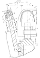
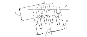
図1に示すように、肌面伸張構造6・7に隣接する切断刃3・4の内刃14の前後幅をAとし、内刃14の肌面伸張体33との隣接端から肌面伸張体33の前後中心までの前後距離をBとするとき、前者の前後幅Aと後者の前後距離Bが不等式(A<B)を満足するように設定する。
As shown in FIG. 1, the front-rear width of the inner blade 14 of the cutting blades 3 and 4 adjacent to the skin surface stretching structures 6 and 7 is A, and the skin surface extends from the adjacent end of the inner blade 14 with the skin surface extension body 33. When the longitudinal distance to the longitudinal center of the body 33 is B, the former longitudinal width A and the latter longitudinal distance B are set so as to satisfy the inequality (A <B).
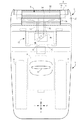
図6に示すように、肌面伸張体33の左右幅をCとし、肌面伸張構造6・7に隣接する切断刃3・4の外刃13の左右幅をDとし、内刃14の左右幅をEとするとき、先の左右幅C、D、Eのそれぞれが不等式(E/2<C<D)を満足するように設定する。
As shown in FIG. 6, the left and right width of the skin surface extending body 33 is C, the left and right widths of the outer blades 13 of the cutting blades 3 and 4 adjacent to the skin surface extending structures 6 and 7 are D, and When the width is E, the left and right widths C, D, and E are set so as to satisfy the inequality (E / 2 <C <D).
肌面伸張体33の左右幅をCとし、肌面伸張構造6・7に隣接する切断刃3・4の外刃13の左右幅をDとし、内刃14の左右幅をEとするとき、先の左右幅C、D、Eのそれぞれが不等式(E≦C≦D)を満足するように設定する。
When the left and right width of the skin surface extending body 33 is C, the left and right width of the outer blade 13 of the cutting blades 3 and 4 adjacent to the skin surface extending structure 6 and 7 is D, and the left and right width of the inner blade 14 is E, Each of the left and right widths C, D, and E is set so as to satisfy the inequality (E ≦ C ≦ D).
図1に示すように、肌面伸張構造6・7に隣接する切断刃3・4の前後中心を通る切断刃中心軸Pと、肌面伸張構造6・7の前後中心を通る肌面伸張中心軸Qを想定するとき、肌面伸張中心軸Qを切断刃中心軸Pに対して傾斜させて、肌面伸張体33を切断刃3・4から離れる向きに傾斜させる。
As shown in FIG. 1, the cutting blade center axis P passing through the front and rear centers of the cutting blades 3 and 4 adjacent to the skin surface stretching structures 6 and 7 and the skin surface stretching center passing through the front and back centers of the skin surface stretching structures 6 and 7 When the axis Q is assumed, the skin surface extension center axis Q is inclined with respect to the cutting blade center axis P, and the skin surface extension body 33 is inclined in a direction away from the cutting blades 3 and 4.
肌面伸張体駆動構造は、肌面伸張体33を肌面伸張中心軸Qに沿って往復駆動するように構成する。往復駆動される肌面伸張体33で肌面を断続的に伸張操作する。
The skin surface extension body drive structure is configured to reciprocate the skin surface extension body 33 along the skin surface extension center axis Q. The skin surface is intermittently extended by the skin surface extending body 33 that is driven to reciprocate.
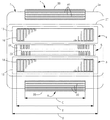
図4に示すように、肌面伸張体駆動構造は、往復動する駆動カム44と、駆動カム44の往復動作を受けて肌面伸張体33を肌面伸張中心軸Qに沿って往復駆動する従動カム45とを備えている。駆動カム44はかみそりヘッド2に配置した往復駆動体23・24に設け、従動カム45は肌面伸張体33を支持する肌面伸張軸36に設ける。
As shown in FIG. 4, the skin surface extending body drive structure reciprocates the skin surface extending body 33 along the skin surface extending center axis Q in response to the reciprocating drive cam 44 and the reciprocating motion of the drive cam 44. And a driven cam 45. The drive cam 44 is provided on the reciprocating drive bodies 23 and 24 disposed on the razor head 2, and the driven cam 45 is provided on the skin surface extending shaft 36 that supports the skin surface extending body 33.
図7に示すように、肌面伸張体駆動構造は、肌面伸張体33を肌面伸張中心軸Qに沿って少なくとも一方向へ駆動操作するソレノイド54を備えている。肌面伸張体33を支持する肌面伸張軸36を、ソレノイド54のプランジャー56に同行移動可能に連結する。
As shown in FIG. 7, the skin surface stretching body drive structure includes a solenoid 54 that drives the skin surface stretching body 33 in at least one direction along the skin surface stretching center axis Q. A skin surface extending shaft 36 that supports the skin surface extending body 33 is connected to a plunger 56 of a solenoid 54 so as to be able to move together.
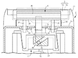
図8に示すように、肌面伸張体駆動構造は、肌面伸張用モーター73と、肌面伸張用モーター73の出力軸に固定したクランク体74と、クランク体74に相対回転自在に連結した駆動ロッド75を備えている。かみそりヘッド2のヘッドフレーム2aで往復スライド可能に案内支持した肌面伸張体33と駆動ロッド75とを同行移動可能に連結する。
As shown in FIG. 8, the skin surface extending body driving structure is connected to the skin surface extending motor 73, the crank body 74 fixed to the output shaft of the skin surface extending motor 73, and the crank body 74 so as to be relatively rotatable. A drive rod 75 is provided. The skin surface extending body 33 guided and supported by the head frame 2a of the razor head 2 so as to be reciprocally slidable and the drive rod 75 are coupled so as to be movable together.
上突湾曲状の外刃13の周面と切断刃中心軸Pとの交差部を通り、切断刃中心軸Pと直交する頂部接線Rを想定するとき、図5に示すように、肌面伸張体33の往復軌跡Sの中途部が前記頂部接線Rと交差するように肌面伸張体33を配置する。
When assuming a top tangent line R passing through the intersection of the peripheral surface of the outer blade 13 having a curved shape and the cutting blade central axis P and orthogonal to the cutting blade central axis P, as shown in FIG. The skin surface extending body 33 is arranged so that the midway part of the reciprocating locus S of the body 33 intersects the top tangent line R.
かみそりヘッド2に複数の切断刃3・4を配置し、かみそりヘッド2の前後端に位置する切断刃3・4の前側および後側のそれぞれに肌面伸張構造6・7を隣接配置する。
A plurality of cutting blades 3, 4 are arranged on the razor head 2, and skin surface extending structures 6, 7 are arranged adjacent to the front and rear sides of the cutting blades 3, 4 positioned at the front and rear ends of the razor head 2.
前後の肌面伸張体駆動構造は、前後の肌面伸張体33が前記頂部接線Rを上下逆向きに通過するように構成する。
The front and rear skin extension body driving structure is configured such that the front and rear skin extension bodies 33 pass through the top tangent line R in the upside down direction.
前後の肌面伸張体駆動構造は、前後の肌面伸張体33が前記頂部接線Rを上下同方向へ同時に通過するように構成する。
The front and rear skin extension body driving structure is configured such that the front and rear skin extension bodies 33 simultaneously pass through the top tangent line R in the same direction in the vertical direction.
図3に示すように、肌面と接触する肌面伸張体33の肌接触面39を曲面状に形成する。
As shown in FIG. 3, the skin contact surface 39 of the skin surface extension body 33 which contacts a skin surface is formed in a curved surface shape.
肌面伸張体33の肌接触面39に、肌面を伸張操作する肌押圧片40を設ける。
A skin pressing piece 40 for extending the skin surface is provided on the skin contact surface 39 of the skin surface extending body 33.
切断刃3・4の内刃14とモーター8との間に、モーター動力を往復動力に変換して内刃14に伝動する内刃駆動構造を設ける。肌面伸張体33による単位時間当たりの肌伸張操作数を、前後の切断刃3・4の内刃14の単位時間当たりの往復動数より小さく設定する。
An inner blade drive structure is provided between the inner blade 14 of the cutting blades 3 and 4 and the motor 8 to convert motor power into reciprocating power and transmit it to the inner blade 14. The number of skin stretching operations per unit time by the skin surface stretching body 33 is set to be smaller than the number of reciprocating motions per unit time of the inner blades 14 of the front and rear cutting blades 3 and 4.
図8に示すように、肌面伸張体33は、固定刃62と、固定刃62に対して往復駆動される可動刃63とを備えている。肌面伸張体33は切断刃3・4と協同してひげ切断を行う。
As shown in FIG. 8, the skin surface extending body 33 includes a fixed blade 62 and a movable blade 63 that is driven to reciprocate with respect to the fixed blade 62. The skin surface extending body 33 performs beard cutting in cooperation with the cutting blades 3 and 4.
図11に示すように、肌面伸張構造6・7の肌面伸張体を回転駆動されるローラー33で構成する。ローラー33の周面に、肌面を断続的に伸張操作する肌押圧片91を設ける。
As shown in FIG. 11, the skin surface extension body of the skin surface extension structures 6 and 7 is composed of a roller 33 that is rotationally driven. A skin pressing piece 91 for intermittently extending the skin surface is provided on the peripheral surface of the roller 33.
肌面伸張体駆動構造は、モーター8の回転動力を減速する減速機構81を備えている。減速機構81で減速された回転動力をローラー33に伝動して、ローラー33の駆動回転数をモーター8の駆動回転数より小さく設定する。
The skin surface extending body drive structure includes a speed reduction mechanism 81 that reduces the rotational power of the motor 8. The rotational power decelerated by the speed reduction mechanism 81 is transmitted to the roller 33, and the driving rotational speed of the roller 33 is set smaller than the driving rotational speed of the motor 8.
肌面伸張体駆動構造は、モーター8の回転動力を減速する減速機構81と、減速機構81の減速動力をローラー33へ伝動する伝動構造82とを備えている。減速機構81の出力軸86を中心にして、ローラー33および伝動構造82を前後傾動操作して、切断刃3・4とローラー33の前後の隣接間隔を調整できるようにする。
The skin extension body driving structure includes a speed reduction mechanism 81 that reduces the rotational power of the motor 8 and a power transmission structure 82 that transmits the speed reduction power of the speed reduction mechanism 81 to the roller 33. The roller 33 and the transmission structure 82 are tilted back and forth around the output shaft 86 of the speed reduction mechanism 81 so that the adjacent distance between the cutting blades 3 and 4 and the roller 33 can be adjusted.
本発明に係る電気かみそりにおいては、かみそりヘッド2に、内刃14と外刃13を備えた切断刃3・4と、切断刃3・4に隣接配置される肌面伸張構造6・7とを設けるようにした。また、肌面伸張構造6・7は肌伸ばしを行う肌面伸張体33と、駆動動力を肌面伸張体33に伝動する肌面伸張体駆動構造を備えるようにした。使用時には、肌面伸張体駆動構造を介して駆動動力を受けた肌面伸張体33が、肌面を切断刃3・4から離れる向きへ断続的に伸張操作できるようにした。
In the electric razor according to the present invention, the razor head 2 includes the cutting blades 3 and 4 having the inner blade 14 and the outer blade 13, and the skin surface extending structures 6 and 7 disposed adjacent to the cutting blades 3 and 4. I made it. The skin surface stretching structures 6 and 7 are provided with a skin surface stretching body 33 that stretches the skin and a skin surface stretching body driving structure that transmits driving power to the skin surface stretching body 33. In use, the skin surface stretching body 33 that received the driving power through the skin surface stretching body drive structure was able to intermittently stretch the skin surface in a direction away from the cutting blades 3 and 4.
上記のように本発明においては、肌面を肌面伸張体33で断続的に伸張操作して、肌面に倒れこんだひげを起立させるので、肌面伸張体33と肌面の接触機会を大幅に減少して、肌面伸張体33の肌面に対する負担を著しく軽減でき、ひげ切断後の肌面にヒリ付きが生じるのを解消できる。また、肌面を肌面伸張体33で切断刃3・4から離れる向きへ断続的に伸張操作するので、ローラーの回転力を作用させて肌面を伸ばしていた従来の肌面伸張構造に比べて、肌面を効果的に伸張させて倒れこんだひげを起立し、切断刃3・4と肌面伸張体33とが協同して行なうひげ切断をより効果的に行うことができる。
As described above, in the present invention, the skin surface is intermittently stretched by the skin surface stretching body 33 to raise the beard that has fallen on the skin surface. This significantly reduces the burden on the skin surface of the skin surface extension body 33, and can eliminate the occurrence of bruising on the skin surface after cutting the beard. In addition, since the skin surface is intermittently stretched in the direction away from the cutting blades 3 and 4 with the skin surface stretching body 33, compared to the conventional skin surface stretching structure in which the skin surface is stretched by the rotational force of the roller. Thus, it is possible to more effectively perform the beard cutting performed in cooperation with the cutting blades 3 and 4 and the skin surface extending body 33 by raising the beard that is effectively stretched by the skin surface.
切断刃3・4の内刃14の前後幅Aと、内刃14から肌面伸張体33の前後中心までの前後距離Bとの関係が、不等式(A<B)を満足するように配置してあると、前後の肌面伸張体33を前後距離Bの分だけ前後の切断刃3・4から離れた位置に位置させることができる。また、肌面伸張体33を前後距離Bの分だけ離れた位置に位置させることにより、肌面伸張体33による肌面の伸張作用が切断刃3・4の近傍の肌面におよぶのを制限しながら、肌面に倒れこんだひげを起立させて前後の切断刃3・4で切断することができる。従って、肌面伸張体33が肌面に断続的に作用することと相俟って、肌面の伸張および擦過の負担を軽減しながら肌面に倒れこんだひげを起立できる。
The cutting blades 3 and 4 are arranged so that the front-rear width A of the inner blade 14 and the front-rear distance B from the inner blade 14 to the front-rear center of the skin extension 33 satisfy the inequality (A <B). In this case, the front and rear skin extension members 33 can be positioned at positions separated from the front and rear cutting blades 3 and 4 by the front and rear distance B. Further, by positioning the skin surface stretching body 33 at a position separated by the front-rear distance B, the skin surface stretching action by the skin surface stretching body 33 is limited to the skin surface near the cutting blades 3 and 4. On the other hand, it is possible to cut with the front and rear cutting blades 3 and 4 while raising the beard that has fallen on the skin surface. Accordingly, coupled with the fact that the skin surface stretching body 33 acts intermittently on the skin surface, it is possible to stand a beard that has fallen on the skin surface while reducing the burden of stretching and rubbing the skin surface.
肌面伸張体33の左右幅Cと、切断刃3・4の外刃13の左右幅Dと、内刃14の左右幅Eの関係が、不等式(E/2<C<D)を満足するように設定してあると、肌面伸張体33の左右幅Cを、外刃13の左右幅Dや内刃14の左右幅Eより小さくすることができる。これに伴い、平面から見る状態における肌面伸張体33を、かみそりヘッド2の外郭線の内側に位置させて、かみそりヘッド2において肌面伸張体33がかさ張るのを解消しながら、切断刃3・4と接触する肌面に倒れこんだひげを起立することができる。
The relationship between the left-right width C of the skin surface extending body 33, the left-right width D of the outer cutter 13 of the cutting blades 3 and 4, and the left-right width E of the inner cutter 14 satisfies the inequality (E / 2 <C <D). If set in this way, the left-right width C of the skin surface extending body 33 can be made smaller than the left-right width D of the outer cutter 13 and the left-right width E of the inner cutter 14. Accordingly, the skin surface extension body 33 in a state viewed from a plane is positioned inside the contour line of the razor head 2, and the skin surface extension body 33 is prevented from becoming bulky in the razor head 2. The beard that has fallen into the skin surface that comes into contact with 4 can be erected.
肌面伸張体33の左右幅Cと、切断刃3・4の外刃13の左右幅Dと、内刃14の左右幅Eの関係は、不等式(E≦C≦D)を満足するように設定することができる。その場合には、肌面伸張体33の左右幅Cが、外刃13の左右幅Dと同じか、それより小さくなる。また、肌面伸張体33の左右幅Cが、内刃14の左右幅Eと同じか、それより大きくなる。あるいは、外刃13の左右幅Dと、内刃14の左右幅Eと、肌面伸張体33の左右幅Cが同じ大きさになる。いずれの場合にも、平面視における肌面伸張体33が、外刃13の左右幅Dを越えてかみそりヘッド2の外郭線の外へ突出するのを解消できるので、かみそりヘッド2において肌面伸張体33がかさ張るのを解消しながら、肌面に倒れこんだひげを起立することができる。
The relationship between the left-right width C of the skin extension member 33, the left-right width D of the outer cutter 13 of the cutting blades 3 and 4, and the left-right width E of the inner cutter 14 satisfies the inequality (E ≦ C ≦ D). Can be set. In that case, the left-right width C of the skin surface extending body 33 is the same as or smaller than the left-right width D of the outer blade 13. Moreover, the left-right width C of the skin surface extending body 33 is the same as or larger than the left-right width E of the inner blade 14. Alternatively, the left-right width D of the outer cutter 13, the left-right width E of the inner cutter 14, and the left-right width C of the skin surface extending body 33 are the same. In any case, it is possible to eliminate the skin surface extending body 33 in plan view from projecting out of the outline of the razor head 2 beyond the lateral width D of the outer blade 13, so that the skin surface extension in the razor head 2 is achieved. While eliminating the bulkiness of the body 33, it is possible to stand the beard that has fallen on the skin surface.
肌面伸張中心軸Qを切断刃中心軸Pに対して傾斜させて、肌面伸張体33を切断刃3・4から離れる向きに傾斜させると、ひげそり時に切断刃3・4に密着した肌面を、肌面伸張体33で切断刃3・4から離れる向きに押圧できる。従って、肌面をより大きく伸張させて、肌面に倒れこんだひげをさらに効果的に起立させ切断刃3・4で切断することができる。
When the skin surface stretching center axis Q is tilted with respect to the cutting blade center axis P, and the skin surface stretching body 33 is tilted away from the cutting blades 3 and 4, the skin surface that is in close contact with the cutting blades 3 and 4 during shaving. Can be pressed in a direction away from the cutting blades 3 and 4 by the skin surface extending body 33. Accordingly, the skin surface can be stretched more greatly, and the beard that has fallen into the skin surface can be erected more effectively and cut with the cutting blades 3 and 4.
肌面伸張体33を肌面伸張中心軸Qに沿って往復駆動する形態の肌面伸張体駆動構造によれば、肌面伸張体33が肌面伸張中心軸Qに沿って一往復する進退動作のうち、肌面伸張体33と肌面とが接触する機会を最大でも進出動作時のみに限って、肌面を断続的に伸張操作することができる。従って、肌面が肌面伸張体33で不必要に伸張操作され、あるいは連続して擦られるのを解消して、肌面伸張体33による肌面の負担をさらに軽減することができる。
According to the skin surface stretching body drive structure in which the skin surface stretching body 33 is driven to reciprocate along the skin surface stretching center axis Q, the skin surface stretching body 33 reciprocates once along the skin surface stretching center axis Q. Of these, the skin surface can be intermittently stretched only when the skin surface stretching body 33 and the skin surface are in contact with each other only at the time of the advance operation. Therefore, it is possible to eliminate the unnecessary stretching operation or continuous rubbing of the skin surface by the skin surface stretching body 33, and to further reduce the burden on the skin surface by the skin surface stretching body 33.
往復動する駆動カム44と、肌面伸張中心軸Qに沿って肌面伸張体33を往復駆動する従動カム45を備えた肌面伸張体駆動構造によれば、肌面伸張体駆動構造がいたずらに複雑になるのを避けながら、肌面伸張体33を確実に往復駆動して肌面を伸張操作できる。また、かみそりヘッド2に配置した往復駆動体23・24に駆動カム44を設け、肌面伸張体33を支持する肌面伸張軸36に従動カム45を設けると、肌面伸張体駆動構造を設けることに伴う部品点数の増加を防止して、肌面伸張体駆動構造をより低コストで製造することができる。とくに、往復駆動体23・24として振動子本体23・24を利用し、従動カム45を肌面伸張軸36に設ける場合には、振動子本体23・24を成形する際に駆動カム44を一体に形成でき、あるいは肌面伸張軸36を成形する際に従動カム45を一体に形成できるので、肌面伸張体駆動構造をさらに低コスト化できる。
According to the skin surface extending body driving structure including the reciprocating drive cam 44 and the driven cam 45 that reciprocates the skin surface extending body 33 along the skin surface extending central axis Q, the skin surface extending body driving structure is mischievous. The skin surface stretching body 33 can be reliably driven to reciprocate and the skin surface can be stretched while avoiding the complexity. Further, when the reciprocating drive bodies 23 and 24 arranged on the razor head 2 are provided with the drive cam 44 and the driven cam 45 is provided with the skin surface extension shaft 36 that supports the skin surface extension body 33, a skin surface extension body drive structure is provided. Accordingly, an increase in the number of parts can be prevented, and the skin surface extension body driving structure can be manufactured at a lower cost. In particular, when the vibrator main bodies 23 and 24 are used as the reciprocating drive bodies 23 and 24 and the driven cam 45 is provided on the skin extension shaft 36, the drive cam 44 is integrated when the vibrator main bodies 23 and 24 are formed. Since the driven cam 45 can be integrally formed when the skin surface extending shaft 36 is molded, the skin surface extending body driving structure can be further reduced in cost.
ソレノイド54を駆動源とし、そのプランジャー56に肌面伸張体33の肌面伸張軸36を同行移動可能に連結する肌面伸張体駆動構造によれば、切断刃3・4の駆動タイミングとは無関係に肌面伸張体33を往復駆動できる。例えば、肌面伸張体33の単位時間当たりの進出数や、肌面伸張体33の進出タイミングなどを適宜設定することができ、あるいは、単位時間当たりの進出数や、肌面伸張体33の進出タイミングなどをランダムに設定することができる。従って、ひげの硬軟や、ひげ密度の違いなどのひげ特性の違いに応じて、肌面伸張体33の動作状態を自由に設定し好適化できる。さらに、本体ケース1に調整構造を設けておくことにより、ユーザー自身が肌面伸張体33の動作状態を調整して好みの状態に設定することができる。
According to the skin surface extending body drive structure in which the solenoid 54 is used as a drive source and the skin surface extending shaft 36 of the skin surface extending body 33 is connected to the plunger 56 so as to be able to move together, the drive timing of the cutting blades 3 and 4 is determined. The skin surface extending body 33 can be driven back and forth irrespectively. For example, the number of advancements per unit time of the skin extension body 33, the advancement timing of the skin extension body 33, and the like can be set as appropriate, or the number of advancements per unit time and the advancement of the skin extension body 33 can be set. Timing etc. can be set at random. Therefore, the operating state of the skin surface stretching body 33 can be freely set and optimized according to differences in beard characteristics such as beard hardness and beard density. Furthermore, by providing the main body case 1 with an adjustment structure, the user can adjust the operating state of the skin surface extending body 33 and set it to a desired state.
肌面伸張用モーター73と、クランク体74と、駆動ロッド75などで構成した肌面伸張体駆動構造によれば、切断刃3・4の駆動タイミングとは無関係に肌面伸張体33を往復駆動できる。従って、上記の肌面伸張体駆動構造と同様に、肌面伸張体33の単位時間当たりの進出数や、肌面伸張体33の進出タイミングなどを適宜設定し、あるいはランダムに設定して、ひげの硬軟や、ひげ密度の違いなどのひげ特性の違いに応じて、肌面伸張体33の動作状態を好適化できる。さらに、必要に応じて、ユーザー自身が肌面伸張体33の動作状態を調整して好みの状態に設定することができる。肌面伸張用モーター73の回転動力を、クランク体74と駆動ロッド75で往復動力に変換して肌面伸張体33に伝動するので、肌面伸張体33の進出速度と退入速度の変化をサインカーブ状に変化させることができる。従って、肌面伸張体33の進出端の近傍における速度をゼロに近づけて、肌面に対する刺激を和らげることができる。
According to the skin extension body drive structure composed of the skin extension motor 73, the crank body 74, the drive rod 75, etc., the skin extension body 33 is driven back and forth regardless of the drive timing of the cutting blades 3 and 4. it can. Accordingly, similarly to the above-described skin stretch body driving structure, the number of advancements per unit time of the skin stretch body 33, the advance timing of the skin stretch body 33, and the like are appropriately set or randomly set to The operating state of the skin surface stretching body 33 can be optimized according to differences in beard characteristics such as differences in hardness and beard density. Furthermore, if necessary, the user himself / herself can adjust the operation state of the skin surface stretching body 33 and set it to a desired state. Since the rotational power of the skin surface stretching motor 73 is converted into reciprocating power by the crank body 74 and the drive rod 75 and transmitted to the skin surface stretching body 33, changes in the advance speed and retreat speed of the skin surface stretching body 33 can be changed. It can be changed to a sine curve. Therefore, the speed in the vicinity of the advancing end of the skin surface extending body 33 can be made close to zero, and the stimulation to the skin surface can be eased.
肌面伸張体33の往復軌跡Sの中途部が、頂部接線Rと交差するように肌面伸張体33を配置すると、肌面伸張体33の上面が頂部接線Rを越えたのちの進出領域でのみ、肌面が肌面伸張体33で伸張操作されることになる。つまり、肌面伸張体33による肌面の伸張操作は断続的であるうえに、肌面伸張体33が往復軌跡Sを一往復する時間の半分以下の時間だけ、肌面を肌面伸張体33で伸張操作することになる。従って、肌面伸張体33による肌面の伸張作用を適度に抑止して、肌面の伸張や擦過などの刺激負担を著しく軽減しながら、肌面に倒れこんだひげを起立させて切断することができる。
When the skin surface stretching body 33 is arranged so that the midway part of the reciprocating locus S of the skin surface stretching body 33 intersects the top tangent line R, in the advancing region after the upper surface of the skin surface stretching body 33 exceeds the top tangent line R Only the skin surface is stretched by the skin surface stretching body 33. That is, the skin surface stretching operation by the skin surface stretching body 33 is intermittent, and the skin surface is stretched for only half the time during which the skin surface stretching body 33 travels once on the reciprocating locus S. Will be extended. Therefore, the action of stretching the skin surface by the skin surface stretching body 33 is moderately suppressed, and the beard that has collapsed on the skin surface is raised and cut while significantly reducing the burden of stimulation such as stretching and rubbing the skin surface. Can do.
前後の切断刃3・4の前側および後側のそれぞれに肌面伸張構造6・7を隣接配置すると、かみそりヘッド2を肌面に沿って前後いずれかへスライド操作してひげ切断を行う場合に、かみそりヘッド2のスライド方向下手側の肌面を前後いずれかの肌面伸張体33で伸張操作できるので、肌面に倒れこんだひげを肌面伸張体33で起立させながらひげ切断を効果的に行うことができる。また、切断刃3・4の前後に肌面伸張構造6・7を配置するので、肌面伸張中心軸Qを切断刃中心軸Pに対して切断刃3・4から遠ざかる向きに傾斜させる場合に、かみそりヘッド2をコンパクトに構成できる。なお、肌面伸張中心軸Qが傾斜する肌面伸張構造6・7を前後の切断刃3・4の間に配置した場合には、前後の肌面伸張構造6・7の間に三角形状のデッドスペースが生じるので、かみそりヘッド2をコンパクト化できない。
When the skin surface extension structures 6 and 7 are arranged adjacent to the front and rear sides of the front and rear cutting blades 3 and 4, respectively, when the razor head 2 is slid to the front or back along the skin surface to cut the beard. Since the skin surface on the lower side in the sliding direction of the razor head 2 can be stretched by either the front or back skin stretcher 33, the beard that has fallen on the skin surface can be effectively cut while the beard is raised by the skin stretcher 33. Can be done. Further, since the skin surface extension structures 6 and 7 are arranged before and after the cutting blades 3 and 4, the skin surface extension center axis Q is inclined with respect to the cutting blade center axis P in a direction away from the cutting blades 3 and 4. The razor head 2 can be configured compactly. In addition, when the skin surface stretching structures 6 and 7 in which the skin surface stretching center axis Q is inclined are disposed between the front and rear cutting blades 3 and 4, a triangular shape is formed between the front and back skin surface stretching structures 6 and 7. Since dead space occurs, the razor head 2 cannot be made compact.
前後の肌面伸張体構造を、前後の肌面伸張体33が頂部接線Rを上下逆向きに通過するように構成すると、一方の肌面伸張体33が前記接線Rを越えて上向きに移動するとき、他方の肌面伸張体33を前記接線Rを越えて下向きに移動させて、肌面の伸張を前後で交互に、かつ断続的に行うことができる。従って、肌面伸張体33による肌面の伸張作用を適度に抑止して、肌面に対する負担を著しく軽減しながら、肌面に倒れこんだひげを起立させて切断することができる。
When the front and rear skin extension bodies are configured such that the front and rear skin extension bodies 33 pass through the top tangent line R in the upside down direction, one of the skin extension bodies 33 moves upward beyond the tangent line R. When the other skin surface extension body 33 is moved downward beyond the tangent line R, the skin surface can be alternately and intermittently extended back and forth. Accordingly, it is possible to stand up and cut a beard that has fallen on the skin surface while moderately suppressing the skin surface stretching action by the skin surface stretching body 33 and significantly reducing the burden on the skin surface.
前後の肌面伸張体構造を、前後の肌面伸張体33が前記頂部接線Rを上下同方向へ同時に通過するように構成すると、切断刃3・4に接触している肌面を、前後の肌面伸張体33で同時に強く伸張操作できるので、肌面に倒れこんだひげはもちろんのこと、切断刃3・4で一度切断された短いひげをも同時に起立させて深ぞりすることができる。
When the front and rear skin extension structures are configured so that the front and rear skin extension bodies 33 simultaneously pass the top tangent line R in the same direction, the skin surfaces in contact with the cutting blades 3 and 4 Since the skin stretcher 33 can be strongly stretched at the same time, not only the whiskers that have fallen on the skin surface, but also short whiskers that have been cut once by the cutting blades 3 and 4 can stand up and be deepened at the same time. .
肌接触面39を曲面状に形成した肌面伸張体33によれば、曲面状の肌接触面39が肌面に接触している限り、伸張力が1個所に集中するのを避けて分散させることができるので、肌面伸張体33の肌面に対する肌当りを柔らかでやさしいものとすることができる。
According to the skin surface extension body 33 in which the skin contact surface 39 is formed in a curved shape, as long as the curved skin contact surface 39 is in contact with the skin surface, the extension force is dispersed so as not to concentrate on one place. Therefore, the skin contact of the skin extension body 33 with respect to the skin surface can be made soft and easy.
肌接触面39に肌面を伸張操作する肌押圧片40を設けると、肌当りの柔らかさを損なうことなく、肌面伸張体33が肌面に対して滑り動くのを肌押圧片40で防止して、肌面をしっかりと捕捉し押圧することができる。
When the skin pressing piece 40 for extending the skin surface is provided on the skin contact surface 39, the skin pressing piece 40 prevents the skin surface extending body 33 from sliding with respect to the skin surface without impairing the softness per skin. Thus, the skin surface can be firmly captured and pressed.
肌面伸張体33による単位時間当たりの肌伸張操作数を、前後の切断刃3・4の内刃14の単位時間当たりの往復動数より小さく設定すると、肌面伸張体33と肌面の接触機会を大幅に減少できるので、肌面伸張体33による肌面に対する伸張や擦過などの刺激負担を軽減し、ひげ切断後の肌面のヒリ付きを抑止ないしは解消できる。
When the number of skin stretching operations per unit time by the skin surface stretching body 33 is set to be smaller than the number of reciprocations per unit time of the inner blades 14 of the front and rear cutting blades 3 and 4, contact between the skin surface stretching body 33 and the skin surface Since the opportunity can be greatly reduced, it is possible to reduce the burden of stimulation such as stretching or rubbing on the skin surface by the skin surface stretching body 33, and to suppress or eliminate the bruising of the skin surface after cutting the beard.
固定刃62と可動刃63とを備える肌面伸張体33によれば、肌面伸張体33によって肌面を伸張操作しながら、肌面伸張体33に接触するひげを固定刃62と可動刃63とで切断できる。また、肌面伸張体33で肌面を伸張させた状態においては、切断刃3・4で一度切断された短いひげを、固定刃62に接触する肌面の近傍において起立させて、固定刃62と可動刃63で再切断し深ぞりできる。切断刃3・4のひげ切断作用に加えて、肌面伸張体33によってもひげ切断を行えるので、その分だけひげ切断を効果的に行うことができる。
According to the skin surface extending body 33 including the fixed blade 62 and the movable blade 63, the beard that comes into contact with the skin surface extending body 33 is removed from the fixed blade 62 and the movable blade 63 while the skin surface is extended by the skin surface extending body 33. And can be cut. Further, in a state where the skin surface is extended by the skin surface extending body 33, the short beard once cut by the cutting blades 3 and 4 is raised in the vicinity of the skin surface contacting the fixed blade 62, and the fixed blade 62. And can be re-cut by the movable blade 63 and deeply slid. In addition to the beard cutting action of the cutting blades 3 and 4, the beard cutting can also be performed by the skin surface extending body 33, so that the beard cutting can be effectively performed correspondingly.
肌面伸張体を回転駆動されるローラー33で構成し、その周面に肌押圧片91を設けると、肌押圧片91を肌面に断続的に接触させながら、肌面を伸張操作することができるので、ローラーの周面を肌面に連続して直接作用させていた従来の肌面伸張構造に比べて、肌面への負担を軽減できる。また、肌押圧片91が肌面に押付けられるとき、肌押圧片91は押付け反力を受けて弾性変形するので、肌当りの柔らかさを損なうことなく、ローラー33が肌面に対して滑り動くのを防止して、肌面をしっかりと捕捉し押圧することができる。
When the skin surface extending body is constituted by the roller 33 that is rotationally driven and the skin pressing piece 91 is provided on the peripheral surface thereof, the skin surface can be stretched while the skin pressing piece 91 is intermittently brought into contact with the skin surface. Therefore, the burden on the skin surface can be reduced as compared with the conventional skin surface stretching structure in which the peripheral surface of the roller is directly applied to the skin surface. Further, when the skin pressing piece 91 is pressed against the skin surface, the skin pressing piece 91 is elastically deformed by the pressing reaction force, so that the roller 33 slides on the skin surface without impairing the softness per skin. It is possible to prevent and prevent the skin surface from being firmly captured and pressed.
減速機構81で減速された回転動力をローラー33に伝動して、ローラー33の駆動回転数をモーター8の駆動回転数より小さく設定すると、肌押圧片91と肌面の接触機会を、減速された回転動力の分だけ減少できる。従って、肌面が肌押圧片91で断続的に伸張操作されることと相俟って肌面の負担を軽減し、ひげ切断後の肌面のヒリ付きを軽減できる。
When the rotational power reduced by the speed reduction mechanism 81 is transmitted to the roller 33 and the driving rotational speed of the roller 33 is set to be smaller than the driving rotational speed of the motor 8, the contact opportunity between the skin pressing piece 91 and the skin surface is reduced. It can be reduced by the amount of rotational power. Therefore, in combination with the skin surface being intermittently extended by the skin pressing piece 91, the burden on the skin surface can be reduced, and the skin surface can be prevented from being bruised after cutting the beard.
減速機構81と伝動構造82を備える肌面伸張体駆動構造によれば、ローラー33および伝動構造82を、減速機構81の出力軸86を中心にして前後傾動操作することで、切断刃3・4とローラー33の前後の隣接間隔を調整できる。また、ローラー33の切断刃3・4に対する前後位置を調整することにより、肌面に作用する伸張力を大小に調整できるので、ユーザーの好みに応じた伸長力を肌面に作用させることができる。さらに、ひげの硬軟や、ひげ密度の違いなどのひげ特性の違いに応じて、ローラー33の前後位置を調整して肌面伸張体の動作状態を好適化できる。
According to the skin surface extension body drive structure including the speed reduction mechanism 81 and the transmission structure 82, the cutting blades 3 and 4 are operated by tilting the roller 33 and the transmission structure 82 back and forth around the output shaft 86 of the speed reduction mechanism 81. And the interval between the front and rear of the roller 33 can be adjusted. Further, by adjusting the front / rear position of the roller 33 with respect to the cutting blades 3 and 4, the stretching force acting on the skin surface can be adjusted in magnitude, so that the stretching force according to the user's preference can be exerted on the skin surface. . Furthermore, the operating state of the skin surface extension body can be optimized by adjusting the front-rear position of the roller 33 according to differences in beard characteristics such as beard hardness and beard density.
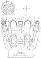
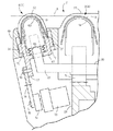
(実施例1) 図1ないし図6は、本発明に係る電気かみそりの実施例1を示している。本発明における前後、左右、上下とは、図2および図3に示す交差矢印と、各矢印の近傍に表記した前後、左右、上下の表示に従う。
Example 1 FIGS. 1 to 6 show Example 1 of an electric shaver according to the present invention. In the present invention, front / rear, left / right, and upper / lower follow the cross arrows shown in FIG. 2 and FIG.
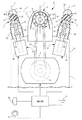
図2および図3において、電気かみそりはグリップを兼ねる本体ケース1と、本体ケース1の上部に設けたかみそりヘッド2とを有し、かみそりヘッド2の前後に第1切断刃(切断刃)3と第2切断刃(切断刃)4を配置し、両切断刃3・4の間にトリマー刃5を配置して構成してある。また、前後の切断刃3・4の前面および後面に隣接して第1肌面伸張構造(肌面伸張構造)6と第2肌面伸張構造(肌面伸張構造)7が配置してある。本体ケース1の内部にはモーター8や2次電池9と制御基板などが設けてあり、本体ケース1の前面には、モーター8への通電状態を切換えるスイッチ10が設けてある。
2 and 3, the electric razor has a main body case 1 also serving as a grip, and a razor head 2 provided on the upper portion of the main body case 1, and a first cutting blade (cutting blade) 3 before and after the razor head 2. A second cutting blade (cutting blade) 4 is arranged, and a trimmer blade 5 is arranged between both cutting blades 3 and 4. A first skin surface stretching structure (skin surface stretching structure) 6 and a second skin surface stretching structure (skin surface stretching structure) 7 are disposed adjacent to the front and rear surfaces of the front and rear cutting blades 3 and 4. A motor 8, a secondary battery 9, a control board, and the like are provided inside the main body case 1, and a switch 10 that switches an energization state to the motor 8 is provided on the front surface of the main body case 1.
第1切断刃3および第2切断刃4は、それぞれ上突湾曲状に保形される網刃からなる外刃13と、外刃13に沿って往復駆動されるスリット刃からなる内刃14とでレシプロ式の切断刃として構成してある。各内刃14とモーター8との間には、モーター8の回転動力を往復動力に変換して内刃14に伝動する内刃駆動構造が設けてある。第1切断刃3および第2切断刃4は、主に短毛を切断するための切断刃として機能する。
The first cutting blade 3 and the second cutting blade 4 are respectively an outer blade 13 made of a mesh blade that is kept in an upwardly curved shape, and an inner blade 14 made of a slit blade that is driven to reciprocate along the outer blade 13. It is configured as a reciprocating cutting blade. Between each inner blade 14 and the motor 8, there is provided an inner blade drive structure that converts the rotational power of the motor 8 into reciprocating power and transmits it to the inner blade 14. The first cutting blade 3 and the second cutting blade 4 mainly function as cutting blades for cutting short hairs.
内刃駆動構造は、モーター8の出力軸に固定した第1偏心カム(偏心カム)15および第2偏心カム(偏心カム)16と、各偏心カム15・16で互いに逆向きに往復駆動される第1振動子17および第2振動子18と、各振動子17・18の往復動作を各内刃14に伝動する第1駆動軸(駆動軸)19および第2駆動軸(駆動軸)20などで構成する。図4に示すように、各振動子17・18は左右一対の振動吸収腕で支持される振動子本体23・24を備えており、その内部に先の偏心カム15・16と係合する受動溝を備えた受動片25・26が段違い状に対向配置してある(図3参照)。符号27は外刃13およびトリマー刃5を支持する外刃ホルダーであり、かみそりヘッド2のヘッドフレーム2aに対して着脱可能に装着してある。トリマー刃5は、それぞれスリット刃で構成した外刃28と内刃29を備えており、内刃29は、第1駆動軸19に固定したトリマー駆動軸30で往復駆動される。トリマー刃5は、主に長めのひげやくせ毛を切断するための切断刃として機能する。
The inner blade drive structure is reciprocally driven in opposite directions by the first eccentric cam (eccentric cam) 15 and the second eccentric cam (eccentric cam) 16 fixed to the output shaft of the motor 8 and the eccentric cams 15 and 16. The first vibrator 17 and the second vibrator 18, the first drive shaft (drive shaft) 19 and the second drive shaft (drive shaft) 20 that transmit the reciprocating motion of the vibrators 17 and 18 to the inner blades 14, etc. Consists of. As shown in FIG. 4, each of the vibrators 17 and 18 includes vibrator main bodies 23 and 24 supported by a pair of left and right vibration absorbing arms, and passively engages with the eccentric cams 15 and 16 therein. Passive pieces 25 and 26 each having a groove are arranged to face each other in a stepped manner (see FIG. 3). Reference numeral 27 denotes an outer blade holder that supports the outer blade 13 and the trimmer blade 5, and is detachably attached to the head frame 2 a of the razor head 2. The trimmer blade 5 includes an outer blade 28 and an inner blade 29 each formed of a slit blade, and the inner blade 29 is reciprocally driven by a trimmer drive shaft 30 fixed to the first drive shaft 19. The trimmer blade 5 mainly functions as a cutting blade for cutting long beards and comb hairs.
第1肌面伸張構造6および第2肌面伸張構造7は、それぞれ肌伸ばしを行う肌面伸張体33と、モーター動力を上下方向の往復動力に変換して、肌面伸張体33に伝動する肌面伸張体駆動構造を備えている。肌面伸張体33は左右横長のベース枠34と、ベース枠34の上面に固定した肌押圧体35と、ベース枠34の下面の左右中央に固定される肌面伸張軸36と、ベース枠34の下面の左右に固定される一対のスライド軸37と、ベース枠34とヘッドフレーム2aの間の隙間を覆うスカート38などで構成する。
The first skin surface stretching structure 6 and the second skin surface stretching structure 7 respectively transmit the skin surface stretching body 33 that performs skin stretching and the skin surface stretching body 33 by converting motor power into reciprocating power in the vertical direction. It has a skin extension body drive structure. The skin surface extending body 33 includes a horizontally long base frame 34, a skin pressing body 35 fixed to the upper surface of the base frame 34, a skin surface extending shaft 36 fixed to the left and right center of the lower surface of the base frame 34, and the base frame 34. It comprises a pair of slide shafts 37 fixed to the left and right of the lower surface, and a skirt 38 that covers the gap between the base frame 34 and the head frame 2a.
肌押圧体35は、適度の摩擦力を発揮するゴムあるいはエラストマーを素材とする成形品からなり、その上面に設けた部分円弧面からなる肌接触面39に沿って、左右に長いリブ状の5個の肌押圧片40を平行に突設して構成してある。このように、肌接触面39を曲面状に形成するのは、肌面伸張体33の肌面に対する肌当りを柔らかでやさしいものとするためである。肌押圧体35が肌面に押付けられるとき、肌押圧片40は押付け反力を受けて弾性変形し、肌当りの柔らかさを損なうことなく、肌面伸張体33が肌面に対して滑り動くのを防止して、肌面をしっかりと捕捉し押圧する。図4に示すように左右のスライド軸37は、ヘッドフレーム2aに固定したガイド41で案内支持されており、これにより肌面伸張体33の全体が上下に往復スライドできる。スカート38は伸縮自在な蛇腹構造の膜体からなり、肌面伸張体33の上下スライドに追随して伸縮変形することにより、ベース枠34とヘッドフレーム2aの間の隙間に指先が挟まれるのを防止し、あるいは先の隙間に毛屑や塵埃が入り込むのを防止する。
The skin pressing body 35 is made of a molded product made of rubber or elastomer that exhibits an appropriate frictional force, and has a rib-like shape 5 that is long to the left and right along a skin contact surface 39 that is a partial arc surface provided on the upper surface thereof. The individual skin pressing pieces 40 project in parallel. Thus, the skin contact surface 39 is formed in a curved shape in order to make the skin contact of the skin surface extension body 33 with respect to the skin surface soft and easy. When the skin pressing body 35 is pressed against the skin surface, the skin pressing piece 40 is elastically deformed by the pressing reaction force, and the skin surface stretching body 33 slides on the skin surface without impairing the softness per skin. Prevents the skin from getting caught and pressed firmly. As shown in FIG. 4, the left and right slide shafts 37 are guided and supported by guides 41 fixed to the head frame 2a, whereby the entire skin surface extending body 33 can be reciprocated up and down. The skirt 38 is made of a stretchable bellows-structured film body, and is stretched and deformed following the up-and-down slide of the skin surface stretching body 33 so that the fingertip is sandwiched in the gap between the base frame 34 and the head frame 2a. Prevent or prevent dust and dust from getting into the gap.
第1肌面伸張構造6と第2肌面伸張構造7は同じ構造であるが、第1肌面伸張構造6の肌面伸張体33が前傾させてあるのに対して、第2肌面伸張構造7の肌面伸張体33は後傾させてある点が異なる。詳しくは、図1および図3に示すように、各切断刃3・4の前後中心を通る垂直の切断刃中心軸をPとし、前後の肌面伸張構造6・7の前後中心を通る肌面伸張中心軸をQとするとき、前側の肌面伸張中心軸Qを前側の切断刃中心軸Pに対して前傾させて、肌面伸張体33を第1切断刃3から離れる向きに傾斜させている。同様に、後側の肌面伸張中心軸Qを後側の切断刃中心軸Pに対して後傾させて、肌面伸張体33を第2切断刃4から離れる向きに傾斜させている。この実施例では、肌面伸張中心軸Qの切断刃中心軸Pに対する前傾角度θ1および後傾角度θ2を、それぞれ13度とした。
The first skin surface stretching structure 6 and the second skin surface stretching structure 7 are the same structure, but the skin surface stretching body 33 of the first skin surface stretching structure 6 is tilted forward, whereas the second skin surface. The skin surface extension body 33 of the extension structure 7 is different in that it is tilted backward. Specifically, as shown in FIG. 1 and FIG. 3, the vertical cutting blade center axis passing through the front and rear centers of the cutting blades 3 and 4 is P, and the skin surface passing through the front and rear centers of the front and rear skin extension structures 6 and 7 When the extension center axis is Q, the front skin extension center axis Q is tilted forward relative to the front cutting blade center axis P, and the skin extension body 33 is inclined away from the first cutting blade 3. ing. Similarly, the rear skin surface extending center axis Q is tilted backward with respect to the rear cutting blade center axis P, and the skin surface extending body 33 is tilted away from the second cutting blade 4. In this example, the forward inclination angle θ1 and the backward inclination angle θ2 of the skin surface extension central axis Q with respect to the cutting blade central axis P were each 13 degrees.
上記のように、各肌面伸張構造6・7の肌面伸張中心軸Qが、切断刃中心軸Pから遠ざかる向きへ前傾ないし後傾させてあると、肌面伸張体33が肌面伸張中心軸Qに沿って往復駆動されるとき、肌押圧片40で肌面を前後の切断刃3・4から離れる向きへ断続的に伸張操作して、肌面に倒れこんだひげを効果的に起立させることができる。なお、肌面伸張中心軸Qが切断刃中心軸Pと平行である場合や、肌面伸張中心軸Qが上記とは逆に切断刃中心軸Pへ近づく向きに傾斜させてある場合には、肌面が肌面伸張体33で凹み操作されるものの、肌面を切断刃3・4から離れる向きへ伸張させることができないので、肌面に倒れこんだひげを起立させるのが難しくなる。
As described above, when the skin surface stretching center axis Q of each skin surface stretching structure 6 or 7 is tilted forward or backward in a direction away from the cutting blade center axis P, the skin surface stretching body 33 stretches the skin surface. When reciprocating along the central axis Q, the skin pressing piece 40 is operated to extend the skin surface intermittently in the direction away from the front and rear cutting blades 3 and 4, effectively removing the beard that has fallen into the skin surface. Can stand. When the skin surface extension center axis Q is parallel to the cutting blade center axis P, or when the skin surface extension center axis Q is inclined to approach the cutting blade center axis P in the opposite direction, Although the skin surface is depressed by the skin surface stretching body 33, the skin surface cannot be stretched away from the cutting blades 3 and 4, so that it is difficult to stand a beard that has fallen on the skin surface.
図3および図4において、肌面伸張体駆動構造は、左右方向へ往復駆動される駆動カム44と、駆動カム44の往復動作を受けて肌面伸張体33を肌面伸張中心軸Qに沿って往復駆動する従動カム45とからなる。駆動カム44は、前後の振動子本体(往復駆動体)23・24に設けた直線状の傾斜溝として形成してある。従動カム45は肌面伸張軸36の下端に形成したカム軸からなり、駆動カム44と常に係合している。こうした肌面伸張体駆動構造によれば、振動子本体23・24が各偏心カム15・16で左右へ往復駆動されるとき、振動子本体23・24の左右動作を肌面伸張体駆動構造で上下動作に変換して、前後の肌面伸張体33を肌面伸張中心軸Qに沿って上下に往復駆動できる。前後の肌面伸張体33を肌面に対して交互に作用させるために、前側の振動子本体23に設けた駆動カム44の傾斜方向と、後側の振動子本体24に設けた駆動カム44の傾斜方向とは、互いに逆向きに傾斜させてある。
3 and 4, the skin surface extending body drive structure includes a drive cam 44 that is reciprocated in the left-right direction, and the skin surface extending body 33 along the skin surface extending center axis Q in response to the reciprocating motion of the drive cam 44. And a driven cam 45 that reciprocates. The drive cam 44 is formed as a linear inclined groove provided in the front and rear vibrator bodies (reciprocating drive bodies) 23 and 24. The driven cam 45 comprises a cam shaft formed at the lower end of the skin surface extending shaft 36 and is always engaged with the drive cam 44. According to such a skin surface extending body driving structure, when the vibrator main bodies 23 and 24 are reciprocated to the left and right by the eccentric cams 15 and 16, the left and right operations of the vibrator bodies 23 and 24 are performed by the skin surface extending body driving structure. By converting to a vertical motion, the front and rear skin extension members 33 can be driven to reciprocate vertically along the skin extension central axis Q. In order to cause the front and rear skin extension members 33 to alternately act on the skin surface, the inclination direction of the drive cam 44 provided on the front vibrator main body 23 and the drive cam 44 provided on the rear vibrator main body 24. Are inclined in directions opposite to each other.
上下方向へ往復駆動される肌面伸張体33は、図5に実線で示す退入位置と、図5に想像線で示す進出位置との間を往復動するが、その往復軌跡Sの高さ位置は、第1、第2の両切断刃3・4の外刃13の頂部接線Rの高さ位置との関係で設定してある。詳しくは、図1に示すように、外刃13の周面と切断刃中心軸Pとの交差部を通り、切断刃中心軸Pと直交する頂部接線Rを想定するとき、肌面伸張体33の往復軌跡Sの上下中央部(中途部)が先の頂部接線Rと交差するように肌面伸張体33を配置している。なお、肌面伸張体33による肌面の伸張ストロークを大きくしたい場合には、肌面伸張体33の往復軌跡Sの上下中央部より下側の部分が頂部接線Rと交差するように肌面伸張体33を配置すればよい。また、肌面伸張体33による肌面の伸張ストロークを小さくしたい場合には、肌面伸張体33の往復軌跡Sの上下中央部より上側の部分が頂部接線Rと交差するように肌面伸張体33を配置すればよい。
The skin surface extending body 33 reciprocated in the vertical direction reciprocates between a retracted position indicated by a solid line in FIG. 5 and an advanced position indicated by an imaginary line in FIG. The position is set in relation to the height position of the top tangent R of the outer blade 13 of both the first and second cutting blades 3 and 4. Specifically, as shown in FIG. 1, when assuming a top tangent line R passing through the intersection of the peripheral surface of the outer blade 13 and the cutting blade central axis P and orthogonal to the cutting blade central axis P, the skin surface extension body 33 is used. The skin surface extending body 33 is arranged so that the vertical center part (midway part) of the reciprocating locus S intersects the top tangent R. In addition, when it is desired to increase the skin surface stretching stroke by the skin surface stretching body 33, the skin surface stretching is performed so that the lower part of the reciprocating locus S of the skin surface stretching body 33 intersects the top tangent line R. The body 33 may be disposed. Further, when it is desired to reduce the skin surface stretching stroke by the skin surface stretching body 33, the skin surface stretching body is such that the upper part of the reciprocating locus S of the skin surface stretching body 33 is above the top tangent R. 33 may be arranged.
前後の切断刃3・4の外刃13が肌面に押付けられるとき、肌面はかみそりヘッド2の押圧力に応じて、前後の外刃13の湾曲形状に沿って凹み変形する。この状態で、肌面伸張体33が頂部接線Rを越えて進出すると、肌面押圧片40が肌面に密着し、さらに肌面を外刃13から遠ざかる向きへ斜めに押上げ操作する。これにより、前後の外刃13と肌面伸張体33との間の肌面が肌面伸張体33で伸張操作され、その結果、肌面に倒れこんだひげを起立させて、前後の両切断刃3・4で切断することができる。
When the outer blades 13 of the front and rear cutting blades 3 and 4 are pressed against the skin surface, the skin surface is recessed and deformed along the curved shape of the front and rear outer blades 13 according to the pressing force of the razor head 2. In this state, when the skin surface extending body 33 advances beyond the top tangent line R, the skin surface pressing piece 40 is brought into close contact with the skin surface, and further, the skin surface is pushed up obliquely in a direction away from the outer blade 13. As a result, the skin surface between the front and rear outer blades 13 and the skin surface extension body 33 is extended by the skin surface extension body 33. As a result, the beard that has fallen down on the skin surface is raised, and both front and rear cuttings are performed. Can be cut with blades 3 and 4.
先に説明したように、肌面伸張体33は、その往復軌跡Sの上下中央部が頂部接線Rと交差するように配置してある。そのため、肌面が伸縮変形することを考慮すると、肌面伸張体33による肌面の実質的な伸張作用は、肌面押圧片40が頂部接線Rを越えたのちの進出範囲で行われることになる。つまり、肌面伸張体33の往復軌跡Sの半分以下の進出範囲で行われることになる。そのため、内刃14が一往復するときの往復時間を基準にすると、肌面伸張体33は先の往復時間の4分の1以下の時間だけ肌面を押圧して、伸張作用を断続的に行うことになる。このように、肌面伸張体33が肌面を伸張操作するときの、単位時間当たりの肌伸張操作数が、前後の切断刃3・4の内刃14の単位時間当たりの往復動数(往動作と復動作の合計値)より小さく設定してあると、肌面伸張体33による肌面の伸張作用を抑止して、肌面に対する負担を著しく軽減しながら、肌面に倒れこんだひげを起立させて切断することができる。
As described above, the skin surface extending body 33 is disposed so that the upper and lower center portions of the reciprocating locus S intersect the top tangent line R. Therefore, considering that the skin surface is stretched and deformed, the substantial stretching action of the skin surface by the skin surface stretching body 33 is performed in the advancing range after the skin surface pressing piece 40 exceeds the top tangent line R. Become. That is, it is performed in an advancing range that is half or less of the reciprocating locus S of the skin surface extending body 33. Therefore, on the basis of the reciprocation time when the inner blade 14 makes one reciprocation, the skin surface stretching body 33 presses the skin surface for a time equal to or less than a quarter of the previous reciprocation time, and the stretching action is intermittently performed. Will do. Thus, the number of skin stretching operations per unit time when the skin surface stretching body 33 stretches the skin surface is equal to the number of reciprocating motions per unit time of the inner blades 14 of the front and rear cutting blades 3 and 4 (outgoing). If it is set to be smaller than the sum of the movement and the return movement), the skin stretching action by the skin stretching body 33 is suppressed and the burden on the skin is remarkably reduced, while the beard that has fallen into the skin is removed. Can be raised and cut.
また、前側の駆動カム44の傾斜方向と、後側の駆動カム44の傾斜方向とは、互いに逆向きに傾斜させてあるので、例えば、前側の肌面伸張体33が上向きに進出駆動される場合には、後側の肌面伸張体33を下向きに退入駆動できる。このように、前後の肌面伸張体33が頂部接線Rを上下逆向きに通過する肌面伸張体駆動構造によれば、肌面伸張体33が肌面を断続的に伸張操作することに加えて、前後の肌面伸張体33で肌面を交互に伸張操作できるので、肌面の負担を軽減することができる。さらに、前後の肌面伸張体33が肌面を同時に伸張作用する場合には、モーター8に大きな駆動負荷が作用するが、肌面伸張体33を肌面に交互に作用させることによりモーター8の駆動負荷を軽減して、モーター8のコストを削減できる。なお、前側の肌面伸張体33が頂部接線Rを通過するタイミングと、後側の肌面伸張体33が頂部接線Rを通過するタイミングとは、モーター8の駆動負荷を軽減するうえで同時であることが好ましいが、両者の通過タイミングに少々のずれがあっても問題はない。
Further, since the tilt direction of the front drive cam 44 and the tilt direction of the rear drive cam 44 are tilted in opposite directions, for example, the front skin extension 33 is driven to advance upward. In this case, the rear skin extension 33 can be driven backwards. As described above, according to the skin stretcher driving structure in which the front and rear skin extension members 33 pass through the top tangent R in the upside down direction, the skin surface extension member 33 intermittently extends the skin surface. Since the skin surface can be alternately stretched by the front and rear skin surface stretching bodies 33, the burden on the skin surface can be reduced. Furthermore, when the front and rear skin extension members 33 extend the skin surface simultaneously, a large driving load is applied to the motor 8, but by alternately applying the skin extension members 33 to the skin surface, the motor 8 The driving load can be reduced and the cost of the motor 8 can be reduced. The timing at which the front skin extension 33 passes through the top tangent R and the timing at which the rear skin extension 33 passes through the top tangent R are simultaneously used to reduce the driving load of the motor 8. Although it is preferable, there is no problem even if there is a slight deviation in the passage timing between the two.
肌面伸張体33による肌面の伸張作用を好適化するために、肌面伸張体33と前後の切断刃3・4の関係寸法を以下のように設定している。図1に示すように、各肌面伸張構造6・7に隣接する前後の切断刃3・4の内刃14の前後幅をAとし、内刃14の肌面伸張体33との隣接端から肌面伸張体33の前後中心までの前後距離をBとするとき、先の前後幅Aと先の前後距離Bが不等式(A<B)を満足するように、前後の肌面伸張体33と前後の切断刃3・4を配置している。
In order to optimize the skin surface stretching action by the skin surface stretching body 33, the dimensions of the skin surface stretching body 33 and the front and rear cutting blades 3 and 4 are set as follows. As shown in FIG. 1, the front-rear width of the inner blade 14 of the front and rear cutting blades 3, 4 adjacent to the skin surface extending structures 6, 7 is A, and the inner blade 14 from the adjacent end to the skin surface extending body 33. When the front-rear distance to the front-rear center of the skin stretch body 33 is B, the front and rear skin stretch bodies 33 and the front-rear width A and the front-rear distance B satisfy the inequality (A <B). Front and rear cutting blades 3 and 4 are arranged.
上記のように、先の前後幅Aと先の前後距離Bに関して不等式(A<B)を満足するように配置してあると、前後の肌面伸張体33を前後距離Bの分だけ前後の切断刃3・4から離れた位置に位置させることができる。また、肌面伸張体33を前後距離Bの分だけ離れた位置に位置させることにより、肌面伸張体33による肌面の伸張作用が切断刃3・4の近傍の肌面におよぶのを抑止しながら、肌面に倒れこんだひげを起立させて前後の切断刃3・4で切断することができる。
As described above, when the front and rear width A and the front and rear distance B are arranged so as to satisfy the inequality (A <B), the front and rear skin extension members 33 are moved back and forth by the front and rear distance B. It can be located at a position away from the cutting blades 3 and 4. Further, by positioning the skin surface stretching body 33 at a position separated by the front-rear distance B, the skin surface stretching action by the skin surface stretching body 33 is prevented from reaching the skin surface near the cutting blades 3 and 4. On the other hand, it is possible to cut with the front and rear cutting blades 3 and 4 while raising the beard that has fallen on the skin surface.
さらに、肌面伸張体33がかみそりヘッド2においてかさ張るのを防ぐために、図6に示すように、肌面伸張体33の左右幅をCとし、前後の肌面伸張構造6・7に隣接する前後の切断刃3・4の外刃13の左右幅をDとし、肌面伸張構造に隣接する切断刃3・4の内刃14の左右幅をEとするとき、左右幅C、D、Eのそれぞれが不等式(E/2<C<D)を満足するように設定している。このように、左右幅C、D、Eが不等式(E/2<C<D)を満足するように設定してあると、肌面伸張体33の左右幅Cを、外刃13の左右幅Dや内刃14の左右幅Eより小さくして、かみそりヘッド2において肌面伸張体33がかさ張るのを解消しながら、切断刃3・4の両側端を除く周面と接触する肌面に倒れこんだひげを起立することができる。なお、ひげ切断刃時には外刃13および内刃14の左右中央付近でひげを捕捉して切断することが多いので、肌面伸張体33の左右幅Cが小さい場合でも、肌面に倒れこんだひげを支障なく起立させながら前後の切断刃3・4で的確に切断することができる。
Furthermore, in order to prevent the skin surface stretching body 33 from becoming bulky in the razor head 2, as shown in FIG. 6, the left and right width of the skin surface stretching body 33 is C, and the front and back adjacent to the front and back skin surface stretching structures 6 and 7 When the left and right widths of the outer blades 13 of the cutting blades 3 and 4 are D and the left and right widths of the inner blades 14 of the cutting blades 3 and 4 adjacent to the skin stretch structure are E, the left and right widths C, D, E Each is set so as to satisfy the inequality (E / 2 <C <D). Thus, when the left and right widths C, D, and E are set so as to satisfy the inequality (E / 2 <C <D), the left and right width C of the skin extension body 33 is set to the left and right width of the outer blade 13. D or smaller than the left-right width E of the inner blade 14, while the razor head 2 eliminates the bulkiness of the skin surface expansion body 33, it falls on the skin surface that contacts the peripheral surface except for both ends of the cutting blades 3 and 4. You can stand up a beard. In many cases, the whisker cutting blade captures and cuts the whisker near the center of the left and right sides of the outer blade 13 and the inner blade 14, so that even if the lateral width C of the skin surface extending body 33 is small, the skin surface collapses. It is possible to accurately cut with the front and rear cutting blades 3 and 4 while raising the beard without hindrance.
実施例1に係る電気かみそりにおいては、かみそりヘッド2の前後2個所に第1切断刃3と第2切断刃4を配置し、前後の切断刃3・4の前側および後側のそれぞれに第1肌面伸張構造6と第2肌面伸張構造7を隣接配置した。このように、各切断刃3・4の前後に第1肌面伸張構造6と第2肌面伸張構造7を配置すると、かみそりヘッド2を肌面に沿って前後いずれかへスライド操作してひげ切断を行う場合に、かみそりヘッド2のスライド方向下手側の肌面を前後いずれかの肌面伸張体33で伸張操作して、肌面に倒れこんだひげを起立させながらひげ切断を効果的に行うことができる。
In the electric razor according to the first embodiment, the first cutting blade 3 and the second cutting blade 4 are disposed at two front and rear positions of the razor head 2, and the first and second cutting blades 3 and 4 are respectively provided on the front side and the rear side. The skin surface stretching structure 6 and the second skin surface stretching structure 7 were disposed adjacent to each other. As described above, when the first skin surface extending structure 6 and the second skin surface extending structure 7 are arranged before and after each of the cutting blades 3 and 4, the razor head 2 is slid to either the front or back along the skin surface, and the When cutting, the skin surface on the lower side in the sliding direction of the razor head 2 is stretched by one of the front and rear skin stretch bodies 33 to effectively cut the beard while raising the beard that has fallen on the skin surface. It can be carried out.
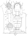
(実施例2) 図7は実施例2に係る電気かみそりを示している。そこでは、かみそりヘッド2の前後中央に1個の切断刃3を設け、切断刃3の前後それぞれに第1肌面伸張構造6と第2肌面伸張構造7を配置した。切断刃3は、実施例1と同様の外刃13と、水平軸回りに回転駆動される内刃14とで、ロータリー式の切断刃として構成する点が実施例1の切断刃と異なっている。内刃14は回転自在に軸支される内刃軸47と、内刃軸47の周面に固定した螺旋状の小刃48とで構成してあり、モーター8の回転動力を巻掛け伝動構造を介して内刃軸47に伝動することにより、内刃14を矢印で示すように反時計回転方向へ回転駆動できるようにしてある。巻掛け伝動構造は、モーター8の出力軸に固定される駆動プーリー49と、内刃軸47に固定される従動プーリー50と、これら両プーリー49・50に巻掛けられる伝動ベルト51とで構成する。
Example 2 FIG. 7 shows an electric razor according to Example 2. There, a single cutting blade 3 was provided at the front and rear center of the razor head 2, and a first skin surface extending structure 6 and a second skin surface extending structure 7 were arranged on the front and rear sides of the cutting blade 3, respectively. The cutting blade 3 is different from the cutting blade of the first embodiment in that the outer blade 13 is the same as that of the first embodiment and the inner blade 14 is rotationally driven around a horizontal axis, and is configured as a rotary cutting blade. . The inner blade 14 is composed of an inner blade shaft 47 that is rotatably supported and a helical small blade 48 that is fixed to the peripheral surface of the inner blade shaft 47, and the rotational power of the motor 8 is wound around the power transmission structure. Is transmitted to the inner blade shaft 47, so that the inner blade 14 can be driven to rotate counterclockwise as indicated by an arrow. The winding transmission structure includes a drive pulley 49 fixed to the output shaft of the motor 8, a driven pulley 50 fixed to the inner blade shaft 47, and a transmission belt 51 wound around both pulleys 49 and 50. .
実施例2においてはソレノイド54を駆動源にして肌面伸張体駆動構造を構成し、肌押圧体35の構造を一部変更した。詳しくはソレノイド54は、ソレノイド本体55とプランジャー56を備えたプッシュ・プル型のソレノイドからなり、そのプランジャー56に、肌面伸張体33を支持する肌面伸張軸36が同行移動可能に連結してある。プランジャー本体55のコイルに順方向電流を供給して、プランジャー56がソレノイド本体55から進出駆動されるとき、肌面伸張体33は頂部接線Rを超えて上方移動し肌面を伸張操作できる。また、ソレノイド本体55のコイルに逆方向電流を供給すると、プランジャー56がソレノイド本体55の内部へ退入駆動される。
In Example 2, the skin surface extending body driving structure was configured using the solenoid 54 as a driving source, and the structure of the skin pressing body 35 was partially changed. Specifically, the solenoid 54 is a push-pull type solenoid having a solenoid body 55 and a plunger 56, and the skin surface extension shaft 36 that supports the skin surface extension body 33 is connected to the plunger 56 so as to be able to move together. It is. When a forward current is supplied to the coil of the plunger main body 55 and the plunger 56 is driven to advance from the solenoid main body 55, the skin surface extending body 33 moves upward beyond the top tangent line R and can extend the skin surface. . Further, when a reverse current is supplied to the coil of the solenoid body 55, the plunger 56 is driven back into the solenoid body 55.
肌押圧体35は、その上周面の肌接触面39を放物線状に形成し、その周面の7個所にリブ状の肌押圧片40を設けるようにした。この実施例における肌押圧片40の肌押圧体35の周面からの突出寸法は、実施例1における肌押圧片40の突出寸法に比べて、充分に小さく設定してあるので、肌面に接触した肌押圧片40がたわみ変形するのを抑止できる。これにより、肌押圧体35の肌当りの柔らかさを損なうことなく、肌面伸張体33が肌面に対して滑り動くのを肌押圧片40で防止して、肌面をしっかりと捕捉し押圧できる。なお、前後の肌面伸張構造6・7の前後中心を通る肌面伸張中心軸Qは、実施例1の電気かみそりと同様に、前後の切断刃中心軸Pに対して前または後へ傾斜させてある。他は、実施例1の電気かみそりと同じであるので、同じ部材に同じ符号を付して、その説明を省略する。以下の実施例においても同じとする。
The skin pressing body 35 has a skin contact surface 39 on its upper peripheral surface formed in a parabolic shape, and rib-shaped skin pressing pieces 40 are provided at seven locations on the peripheral surface. Since the protruding dimension of the skin pressing piece 40 in this embodiment from the peripheral surface of the skin pressing body 35 is set sufficiently smaller than the protruding dimension of the skin pressing piece 40 in the first embodiment, it contacts the skin surface. It is possible to prevent the deformed skin pressing piece 40 from being deformed. Thereby, the skin pressing body 40 prevents the skin surface extension body 33 from sliding on the skin surface without impairing the softness of the skin pressing body 35 per skin, and the skin surface is firmly captured and pressed. it can. Note that the skin surface extension center axis Q passing through the front and rear centers of the front and rear skin extension structures 6 and 7 is inclined forward or backward with respect to the front and rear cutting blade center axes P in the same manner as the electric razor of the first embodiment. It is. Since others are the same as the electric shaver of Example 1, the same code | symbol is attached | subjected to the same member and the description is abbreviate | omitted. The same applies to the following embodiments.
上記のように、ソレノイド54を駆動源にして肌面伸張体駆動構造を構成すると、切断刃3の駆動タイミングとは無関係に肌面伸張体33を往復駆動できる。例えば、肌面伸張体33の単位時間当たりの進出数や、肌面伸張体33の進出タイミングなどを適宜設定することができる。また、単位時間当たりの進出数や、肌面伸張体33の進出タイミングなどをランダムに設定することができる。さらに、調整ダイヤル57を操作することにより、ソレノイド本体55のコイルに対する順方向電流や逆方向電流の供給タイミングを自由に変更できるので、ユーザーの好みに合わせて、肌面伸張体33の単位時間当たりの進出数や進出タイミングを選定することができる。例えば、肌面伸張体33が肌面を伸張操作するときの、単位時間当たりの肌伸張操作数が、前後の切断刃3・4の内刃14の単位時間当たりの往復動数(往動作と復動作の合計値)より小さく設定してある場合には、肌面伸張体33による肌面の伸張作用を抑止して、肌面に対する負担を著しく軽減しながら、肌面に倒れこんだひげを起立させて切断することができる。なお、ソレノイド54は、プッシュ型、あるいはプル型のソレノイドであってもよい。その場合には、補助ばねを併用して肌面伸張体33を退入付勢し、あるいは肌面伸張体33を進出付勢して、プランジャー56を補助ばねの付勢力に抗してソレノイド54で進出駆動し、あるいは退入駆動するとよい。
As described above, when the skin extension body driving structure is configured using the solenoid 54 as a drive source, the skin extension body 33 can be driven back and forth regardless of the drive timing of the cutting blade 3. For example, the number of advancements per unit time of the skin surface extension body 33, the advancement timing of the skin surface extension body 33, and the like can be set as appropriate. In addition, the number of advancements per unit time, the advancement timing of the skin surface extension body 33, and the like can be set at random. Further, by operating the adjustment dial 57, the supply timing of the forward current and the reverse current to the coil of the solenoid body 55 can be freely changed. Therefore, per unit time of the skin extension body 33 according to the user's preference. The number of advancement and the advancement timing can be selected. For example, the number of skin stretching operations per unit time when the skin surface stretching body 33 stretches the skin surface is the number of reciprocating motions per unit time of the inner blades 14 of the front and rear cutting blades 3 and 4 (forward operation and If it is set to be smaller than the total value of the reverse action), the skin surface stretching action by the skin surface stretching body 33 is suppressed and the burden on the skin surface is remarkably reduced, while the beard that has fallen into the skin surface is removed. Can be raised and cut. The solenoid 54 may be a push type or pull type solenoid. In such a case, the auxiliary spring is used together to retreat the skin surface extension body 33, or the skin surface extension body 33 is advanced to bias the plunger 56 against the urging force of the auxiliary spring. It is recommended to drive forward at 54 or drive backward.
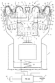
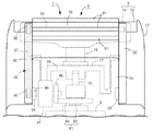
(実施例3) 図8ないし図10は実施例3に係る電気かみそりを示している。そこでは、ヘッドフレーム2aを本体ケース1で上下動可能に支持し、ヘッドフレーム2aの底壁と本体ケース1との間に配置したフロートばね60で、かみそりヘッド2を上下フロート自在に支持した。モーター8はヘッドフレーム2aの内部に配置してあって、かみそりヘッド2に同行して上下フロートする。このように、かみそりヘッド2を上下フロート自在に支持すると、ひげ切断時のかみそりヘッド2が肌面に沿って上下動するので、肌当りをソフトなものとして肌面に対するストレスをやわらげることができる。また、肌面伸張構造が往復動するときの振動が、本体ケース1を握っている手に伝わるのを良く防止できる。
Example 3 FIGS. 8 to 10 show an electric razor according to Example 3. FIG. There, the head frame 2a is supported by the main body case 1 so as to be movable up and down, and the razor head 2 is supported by a float spring 60 disposed between the bottom wall of the head frame 2a and the main body case 1 so as to be able to float up and down. The motor 8 is disposed inside the head frame 2a and accompanies the razor head 2 and floats up and down. Thus, if the razor head 2 is supported so as to float freely, the razor head 2 at the time of cutting the beard moves up and down along the skin surface, so that the skin contact can be made soft and the stress on the skin surface can be reduced. Further, it is possible to well prevent the vibration when the skin surface extending structure reciprocates from being transmitted to the hand holding the main body case 1.
実施例3においては、外刃枠61に固定される網刃からなる固定刃62と、固定刃62に対して往復駆動される可動刃63とで肌面伸張体33を構成し、肌面伸張体33が前後の切断刃3・4と協同してひげ切断を行えるようにした。図9に示すように、スリット刃からなる可動刃63は内刃枠64に固定されており、内刃枠64の底壁と外刃枠61との間に配置した可動刃ばね65で、可動刃63が固定刃62の内面に密着するように付勢してある。前側の可動刃63は、第1駆動軸19に固定した前駆動軸67で左右に往復駆動され、後側の可動刃63は、第2駆動軸20に固定した後駆動軸68で左右に往復駆動される。前駆動軸67はトリマー駆動軸30と一体に形成してある。固定刃62と可動刃63とを備えた肌面伸張体33を上下に往復駆動するために、外刃枠61の前後の左右にスライド軸37を設け、これらのスライド軸37をヘッドフレーム2aに固定したガイド枠69のガイド溝70で上下スライド自在に案内支持している。この実施例における第1肌面伸張構造6と第2肌面伸張構造7は、主に短毛を切断するための切断刃として機能する。
In the third embodiment, the skin surface extending body 33 is configured by a fixed blade 62 formed of a mesh blade fixed to the outer blade frame 61 and a movable blade 63 driven to reciprocate with respect to the fixed blade 62, thereby extending the skin surface. The body 33 can cut the whiskers in cooperation with the front and rear cutting blades 3 and 4. As shown in FIG. 9, the movable blade 63 made of a slit blade is fixed to the inner blade frame 64, and is movable by a movable blade spring 65 disposed between the bottom wall of the inner blade frame 64 and the outer blade frame 61. The blade 63 is biased so as to be in close contact with the inner surface of the fixed blade 62. The front movable blade 63 is reciprocated left and right by a front drive shaft 67 fixed to the first drive shaft 19, and the rear movable blade 63 is reciprocated left and right by a rear drive shaft 68 fixed to the second drive shaft 20. Driven. The front drive shaft 67 is formed integrally with the trimmer drive shaft 30. In order to reciprocate the skin extending body 33 including the fixed blade 62 and the movable blade 63 up and down, slide shafts 37 are provided on the left and right sides of the outer blade frame 61, and these slide shafts 37 are attached to the head frame 2a. The guide groove 70 of the fixed guide frame 69 guides and supports it so that it can slide up and down. The first skin surface extending structure 6 and the second skin surface extending structure 7 in this embodiment mainly function as a cutting blade for cutting short hairs.
肌面伸張体駆動構造は、モーター8に比べて小形の肌面伸張用モーター73と、肌面伸張用モーター73の出力軸に固定した円板状のクランク体74と、クランク体74の出力ピン75に相対回転自在に連結した駆動ロッド76などで構成する。肌面伸張用モーター73は、減速機構を内蔵するギヤードモーターからなり、低速度の回転動力(200rpm)でクランク体74を回転駆動する。このように、肌面伸張用モーター73を駆動源にして肌面伸張体駆動構造を構成すると、切断刃3の駆動タイミングとは無関係に肌面伸張体33を往復駆動できる。例えば、肌面伸張体33の単位時間当たりの進出数や、肌面伸張体33の進出タイミングなどを適宜設定することができる。また、単位時間当たりの進出数や、肌面伸張体33の進出タイミングなどをランダムに設定することができる。
The skin surface extending body drive structure has a smaller skin surface extending motor 73 than the motor 8, a disc-shaped crank body 74 fixed to the output shaft of the skin surface extending motor 73, and an output pin of the crank body 74 The drive rod 76 is connected to 75 so as to be relatively rotatable. The skin surface extending motor 73 is a geared motor with a built-in speed reduction mechanism, and rotationally drives the crank body 74 with low-speed rotational power (200 rpm). Thus, if the skin surface extending body drive structure is configured using the skin surface extending motor 73 as a drive source, the skin surface extending body 33 can be driven back and forth regardless of the drive timing of the cutting blade 3. For example, the number of advancements per unit time of the skin surface extension body 33, the advancement timing of the skin surface extension body 33, and the like can be set as appropriate. In addition, the number of advancements per unit time, the advancement timing of the skin surface extension body 33, and the like can be set at random.
さらに、肌面伸張体33を低速度で往復駆動すると、単位時間当たりの肌伸張操作数を、前後の切断刃3・4の内刃14の単位時間当たりの往復動数(往動作と復動作の合計値)より小さく設定できるので、肌面伸張体33による肌面の伸張作用を抑止して、肌面に対する負担を著しく軽減しながら、肌面に倒れこんだひげを起立させて切断することができる。図9および図10に示すように、駆動ロッド76の上端は、外刃枠61と一体に設けた連結片77に対してピン78で連結される。この肌面伸張体駆動構造によれば、肌面伸張用モーター73の回転動力を、クランク体74と駆動ロッド76で上下方向の往復動力に変換して外刃枠61に伝動できるので、肌面伸張体33を上下に駆動して肌面を断続的に伸張操作しながら、肌面伸張体33の固定刃62と可動刃63とでひげ切断を行うことができる。
Further, when the skin surface stretching body 33 is driven to reciprocate at a low speed, the number of skin stretching operations per unit time is set to the number of reciprocating motions per unit time of the inner blades 14 of the front and rear cutting blades 3 and 4 (forward operation and backward operation). Therefore, it is possible to set the beard that has fallen on the skin surface and cut it while suppressing the skin surface stretching action by the skin surface stretching body 33 and significantly reducing the burden on the skin surface. Can do. As shown in FIGS. 9 and 10, the upper end of the drive rod 76 is connected by a pin 78 to a connecting piece 77 provided integrally with the outer blade frame 61. According to this skin surface extending body drive structure, the rotational power of the skin surface extending motor 73 can be converted into reciprocating power in the vertical direction by the crank body 74 and the drive rod 76 and transmitted to the outer blade frame 61. The whiskers can be cut with the fixed blade 62 and the movable blade 63 of the skin surface stretching body 33 while the skin surface is intermittently stretched by driving the stretching body 33 up and down.
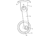
(実施例4) 図11および図12は実施例4に係る電気かみそりを示している。そこでは、実施例2の電気かみそりと同様に、かみそりヘッド2の前後中央に1個の切断刃3を設け、切断刃3の前側に肌面伸張構造6を設けた。肌面伸張構造6は、回転駆動されるローラー33で構成した肌面伸張体と、肌面伸張体駆動構造とで構成した。肌面伸張体駆動構造は、モーター8の回転動力を減速する減速機構81と、減速機構81の減速動力をローラー33へ伝動する巻掛伝動構造(伝動構造)82とで構成する。減速機構81は、モーター8の出力軸に固定される駆動ギヤ83と、駆動ギヤ83と噛合う大径の従動ギヤ84と、従動ギヤ84に噛合うフェースギヤ85と、減速ユニット87(図12参照)などで構成する。駆動ギヤ83と従動ギヤ84との間でモーター8の回転動力を減速し、さらに減速ユニット87で減速することにより、ローラー33の駆動回転数をモーター8の駆動回転数より大幅に小さく設定することができる。例えば、モーター8の駆動回転数が8000rpmであるとき、ローラー33の駆動回転数を100rpmにまで減速できる。図12に示すように、フェースギヤ85の出力軸86は従動ギヤ84の回転中心軸に対して直交させてあり、これにより、モーター8の垂直軸回りの回転動力を水平軸回りの回転動力に変換して巻掛伝動構造82へ伝動している。なお、伝動構造82は巻掛伝動構造である必要はなく、ギヤトレインで構成してあってもよい。
Example 4 FIGS. 11 and 12 show an electric razor according to Example 4. FIG. There, one cutting blade 3 was provided in the front and rear center of the razor head 2 and the skin surface extending structure 6 was provided on the front side of the cutting blade 3 in the same manner as the electric razor in Example 2. The skin surface stretching structure 6 was composed of a skin surface stretching body composed of a roller 33 that was rotationally driven, and a skin surface stretching body driving structure. The skin surface extending body drive structure includes a reduction mechanism 81 that reduces the rotational power of the motor 8 and a winding transmission structure (transmission structure) 82 that transmits the reduction power of the reduction mechanism 81 to the roller 33. The reduction mechanism 81 includes a drive gear 83 fixed to the output shaft of the motor 8, a large-diameter driven gear 84 that meshes with the drive gear 83, a face gear 85 that meshes with the driven gear 84, and a reduction unit 87 (FIG. 12). For example). The rotational speed of the motor 8 is decelerated between the drive gear 83 and the driven gear 84, and further decelerated by the reduction unit 87, so that the rotational speed of the roller 33 is set to be significantly smaller than the rotational speed of the motor 8. Can do. For example, when the rotational speed of the motor 8 is 8000 rpm, the rotational speed of the roller 33 can be reduced to 100 rpm. As shown in FIG. 12, the output shaft 86 of the face gear 85 is orthogonal to the rotation center axis of the driven gear 84, whereby the rotational power about the vertical axis of the motor 8 is changed to rotational power about the horizontal axis. It is converted and transmitted to the winding transmission structure 82. Note that the transmission structure 82 does not have to be a wound transmission structure, and may be configured by a gear train.
ローラー33は、適度の摩擦力を発揮するゴムあるいはエラストマーを素材とする丸軸状の成形品からなり、その中心にローラー軸90が固定され、ローラー周面の4個所に、肌面を断続的に伸張操作するリブ状の肌押圧片91が突設してある。ローラー軸90の両端は左右一対のローラー支持腕92で軸支してある。左右のローラー支持腕92の対向面の下部にはボス93が設けてあり、これらのボス93をヘッドフレーム2aで支持することにより、ローラー33と、ローラー支持腕92と、巻掛伝動構造82の3者を、出力軸86を中心にして前後傾動可能に支持している。ボス93の中心軸線と出力軸86の中心軸線とは一致している。巻掛伝動構造82は、図12に向かって左側のローラー支持腕92の内部に配置してあり、フェースギヤ85の出力軸86に固定される駆動プーリー95と、ローラー軸90に固定される従動プーリー96と、これら両プーリー95・96に巻掛けられる伝動ベルト97とで構成してある。ローラー33は、図11に示す矢印の向きに沿って反時計回転方向へ回転駆動される。なお、肌押圧片91は、ローラー軸90の周面の1個所以上に設けてあればよい。
The roller 33 is a round shaft-shaped molded product made of rubber or elastomer that exhibits an appropriate frictional force. The roller shaft 90 is fixed at the center of the roller 33, and the skin surface is intermittently provided at four locations on the roller circumferential surface. A rib-shaped skin pressing piece 91 that is extended to protrude is provided. Both ends of the roller shaft 90 are pivotally supported by a pair of left and right roller support arms 92. Boss 93 is provided in the lower part of the opposing surface of the left and right roller support arms 92. By supporting these bosses 93 with the head frame 2a, the roller 33, the roller support arm 92, and the winding transmission structure 82 are provided. The three members are supported so as to tilt forward and backward about the output shaft 86. The center axis of the boss 93 and the center axis of the output shaft 86 coincide with each other. The winding transmission structure 82 is arranged inside the roller support arm 92 on the left side as viewed in FIG. 12, and a drive pulley 95 fixed to the output shaft 86 of the face gear 85 and a driven driven fixed to the roller shaft 90. The pulley 96 and a transmission belt 97 wound around the pulleys 95 and 96 are configured. The roller 33 is rotationally driven in the counterclockwise direction along the direction of the arrow shown in FIG. The skin pressing piece 91 may be provided at one or more locations on the peripheral surface of the roller shaft 90.
上記の肌面伸張構造6によれば、切断刃3の内刃14がモーター動力で左右に往復駆動されるとき、ローラー33を同時に回転駆動してリブ状の肌押圧片91で肌面を断続的に伸張操作することができる。これにより、ローラーの周面を肌面に直接作用させていた従来の肌面伸張構造に比べて、肌面の負担を軽減できる。また、モーター8の回転動力を減速機構81で大幅に減速したのち、減速された回転動力でローラー33を駆動するので、肌押圧片91と肌面の接触機会を減少できる。従って、肌面が肌押圧片91で断続的に伸張操作されることと相俟って肌面の負担を軽減し、ひげ切断後の肌面のヒリ付きを軽減できる。
According to the skin surface stretching structure 6 described above, when the inner blade 14 of the cutting blade 3 is reciprocated left and right by motor power, the roller 33 is simultaneously driven to rotate, and the skin surface is intermittently connected by the rib-shaped skin pressing piece 91. Can be stretched. Thereby, the burden of a skin surface can be reduced compared with the conventional skin surface expansion | extension structure which made the peripheral surface of a roller act on the skin surface directly. Further, after the rotational power of the motor 8 is greatly decelerated by the speed reduction mechanism 81, the roller 33 is driven by the reduced rotational power, so the chance of contact between the skin pressing piece 91 and the skin surface can be reduced. Therefore, in combination with the skin surface being intermittently extended by the skin pressing piece 91, the burden on the skin surface can be reduced, and the skin surface can be prevented from being bruised after cutting the beard.
ローラー軸90の両端を左右一対のローラー支持腕92で軸支するので、必要に応じてローラー支持腕92を前後に傾動操作することにより、切断刃3とローラー33の前後の隣接間隔を大小に調整できる。ユーザーは、ローラー支持腕92を傾動操作したのち、図示していないストッパーを操作してローラー支持腕92の前後傾動をロックすることにより、ローラー33を好みの前後位置に固定することができる。なお、図11に実線で示すように、ローラー支持腕92が垂直に近い状態で起立している状態では、ローラー33が切断刃3の近傍に位置して、肌押圧片91の殆どの部分が頂部接線Rより上方へ突出するので、より強い力で肌面を伸張操作してひげを起立することができる。また、想像線で示すように、ローラー支持腕92を前傾させると、肌押圧片91の頂部接線Rからの突出量が小さくなるので、肌面に作用する伸張力を小さくしてローラー33の肌当りを柔らかなものとすることができる。さらに、ローラー33と切断刃3の隣接間隔が大きくなるので、これら両者3・33の間に顎を挟んだ状態でひげ切断を行うことができる。
Since both ends of the roller shaft 90 are pivotally supported by a pair of left and right roller support arms 92, the adjacent distance between the front and rear of the cutting blade 3 and the roller 33 can be increased or decreased by tilting the roller support arm 92 back and forth as necessary. Can be adjusted. The user can fix the roller 33 at a preferred front-rear position by tilting the roller support arm 92 and then operating a stopper (not shown) to lock the front-back tilt of the roller support arm 92. As shown by a solid line in FIG. 11, in a state where the roller support arm 92 stands up in a nearly vertical state, the roller 33 is positioned in the vicinity of the cutting blade 3 and most of the skin pressing piece 91 is Since it protrudes upward from the top tangent line R, it is possible to erect the beard by extending the skin surface with a stronger force. Further, as shown by the imaginary line, when the roller support arm 92 is tilted forward, the amount of protrusion from the top tangent line R of the skin pressing piece 91 is reduced, so that the extension force acting on the skin surface is reduced and the roller 33 The skin can be softened. Furthermore, since the adjacent space | interval of the roller 33 and the cutting blade 3 becomes large, a beard cutting can be performed in the state which pinched | interposed the jaw between these both 3 * 33.
実施例1の電気かみそりにおいて、図6に示すように、肌面伸張体33の左右幅をCとし、肌面伸張構造6・7に隣接する切断刃3・4の外刃13の左右幅をDとし、内刃14の左右幅をEとするとき、左右幅C、D、Eのそれぞれが不等式(E≦C≦D)を満足するように設定できる。その場合には、肌面伸張体33の左右幅Cが、外刃13の左右幅Dと同じか、それより小さくなる。また、肌面伸張体33の左右幅Cが、内刃14の左右幅Eと同じか、それより大きくなる。あるいは、外刃13の左右幅Dと、内刃14の左右幅Eと、肌面伸張体33の左右幅Cが同じ大きさになる。いずれの場合にも、肌面伸張体33が外刃13の左右幅Dを越えてかみそりヘッド2の外郭線の外へ突出するのを解消できるので、かみそりヘッド2において肌面伸張体33がかさ張るのを解消しながら、肌面に倒れこんだひげを起立することができる。
In the electric shaver according to the first embodiment, as shown in FIG. 6, the left and right width of the skin extension body 33 is C, and the left and right widths of the outer blades 13 of the cutting blades 3 and 4 adjacent to the skin extension structures 6 and 7 are as follows. When D is D and the left and right width of the inner blade 14 is E, the left and right widths C, D, and E can be set so as to satisfy the inequality (E ≦ C ≦ D). In that case, the left-right width C of the skin surface extending body 33 is the same as or smaller than the left-right width D of the outer blade 13. Moreover, the left-right width C of the skin surface extending body 33 is the same as or larger than the left-right width E of the inner blade 14. Alternatively, the left-right width D of the outer cutter 13, the left-right width E of the inner cutter 14, and the left-right width C of the skin surface extending body 33 are the same. In any case, since the skin surface extending body 33 can be prevented from projecting outside the contour line of the razor head 2 beyond the lateral width D of the outer blade 13, the skin surface expanding body 33 is bulky in the razor head 2. While eliminating this, you can stand a beard that has fallen into the skin.
実施例1においては、前後の肌面伸張体33が肌面を交互に伸張操作するようにしたが、その必要はない。肌面伸張体駆動構造は、前後の肌面伸張構造6・7の肌面伸張体33のそれぞれが、頂部接線Rを上下同方向へ同時に通過するように構成して、肌面を前後の肌面伸張体33で同時に伸張操作することができる。その場合には、切断刃3・4に接触している肌面を、前後の肌面伸張体33で強く伸張操作できるので、肌面に倒れこんだひげはもちろんのこと、切断刃3・4で一度切断された短いひげをも同時に起立させて深ぞりすることができる。なお、前後の肌面伸張体33で肌面を同時に伸張作用する場合には、モーター8に大きな駆動負荷が作用するので、モーター出力が大きなモーター8を選定する必要がある。
In the first embodiment, the front and rear skin extension members 33 alternately extend the skin surface, but this is not necessary. The skin extension body driving structure is configured such that each of the skin extension bodies 33 of the front and rear skin extension structures 6 and 7 passes through the top tangent line R in the same direction in the vertical direction, so The surface expansion body 33 can be extended simultaneously. In that case, the skin surface in contact with the cutting blades 3 and 4 can be strongly stretched by the front and rear skin surface stretching bodies 33, so that the cutting blades 3 and 4 as well as the beard that has fallen into the skin surface can be used. A short beard that has been cut once in step 3 can also be raised and deepened at the same time. Note that when the skin surface is stretched simultaneously by the front and rear skin surface stretching bodies 33, a large driving load acts on the motor 8, and therefore it is necessary to select the motor 8 having a large motor output.
また、実施例1においては、駆動カム44を傾斜溝で構成し、従動カム45をカム軸で構成したが、その必要はなく、駆動カム44をカム軸で構成し、従動カム45を傾斜溝で構成することができる。さらに、駆動カム44と従動カム45は、傾斜溝とカム軸以外のカム要素の組合わせで構成することができ、要は振動子本体23・24の左右動作を上下動作に変換できるカム構造であればよい。駆動カム44は、振動子本体23・24以外の往復駆動体に設けてあってもよい。肌押圧体35の上面は、正面から見て上突湾曲状に形成してあってもよく、あるいは波型に形成してあってもよい。
In the first embodiment, the drive cam 44 is formed of an inclined groove and the driven cam 45 is formed of a cam shaft. However, the drive cam 44 is formed of a cam shaft and the driven cam 45 is formed of an inclined groove. Can be configured. Furthermore, the drive cam 44 and the driven cam 45 can be configured by a combination of an inclined groove and a cam element other than the cam shaft. In short, the cam structure can convert the left and right movements of the vibrator bodies 23 and 24 into vertical movements. I just need it. The drive cam 44 may be provided in a reciprocating drive body other than the vibrator main bodies 23 and 24. The upper surface of the skin pressing body 35 may be formed in an upwardly curved shape as viewed from the front, or may be formed in a corrugated shape.
実施例3においては、肌面伸張用モーター73と、クランク体74と、駆動ロッド76で肌面伸張体駆動構造を構成したが、その必要はない。例えば、肌面伸張用モーター73の出力軸に固定した偏心カムと、偏心カムに連結した駆動ロッド76で肌面伸張体駆動構造を構成することができ、要は肌面伸張用モーター73の回転動力を上下方向の往復動力に変換できる動作変換構造であればよい。実施例4における肌面伸張体33はローラー状に形成する必要はなく、楕円状、頂部が丸められた多角形状、あるいは3以上の頂部を備えた内サイクロイド形状などに形成してあってもよい。
In the third embodiment, the skin surface extending body driving structure is configured by the skin surface extending motor 73, the crank body 74, and the drive rod 76, but it is not necessary. For example, an eccentric cam fixed to the output shaft of the skin surface extending motor 73 and a drive rod 76 connected to the eccentric cam can constitute a skin surface extending body driving structure. Any motion conversion structure that can convert power into reciprocating power in the vertical direction may be used. The skin surface extension 33 in Example 4 does not need to be formed in a roller shape, and may be formed in an elliptical shape, a polygonal shape with rounded tops, or an inner cycloid shape having three or more tops. .