JP6284342B2 - Photovoltaic power generation apparatus and photovoltaic power generation control method - Google Patents
Photovoltaic power generation apparatus and photovoltaic power generation control method Download PDFInfo
- Publication number
- JP6284342B2 JP6284342B2 JP2013225963A JP2013225963A JP6284342B2 JP 6284342 B2 JP6284342 B2 JP 6284342B2 JP 2013225963 A JP2013225963 A JP 2013225963A JP 2013225963 A JP2013225963 A JP 2013225963A JP 6284342 B2 JP6284342 B2 JP 6284342B2
- Authority
- JP
- Japan
- Prior art keywords
- output power
- voltage
- control
- power
- control voltage
- Prior art date
- Legal status (The legal status is an assumption and is not a legal conclusion. Google has not performed a legal analysis and makes no representation as to the accuracy of the status listed.)
- Active
Links
- 238000000034 method Methods 0.000 title claims description 79
- 238000010248 power generation Methods 0.000 title claims description 64
- 230000008569 process Effects 0.000 claims description 45
- 230000005855 radiation Effects 0.000 description 32
- 230000007423 decrease Effects 0.000 description 18
- 238000010586 diagram Methods 0.000 description 10
- 238000004364 calculation method Methods 0.000 description 9
- 230000008859 change Effects 0.000 description 9
- 230000003247 decreasing effect Effects 0.000 description 9
- 230000009194 climbing Effects 0.000 description 6
- 230000007704 transition Effects 0.000 description 4
- 238000006243 chemical reaction Methods 0.000 description 3
- 238000013500 data storage Methods 0.000 description 3
- 238000001514 detection method Methods 0.000 description 2
- 230000016507 interphase Effects 0.000 description 2
- 230000001771 impaired effect Effects 0.000 description 1
- 238000012986 modification Methods 0.000 description 1
- 230000004048 modification Effects 0.000 description 1
- 238000012544 monitoring process Methods 0.000 description 1
- 230000003287 optical effect Effects 0.000 description 1
- 239000004065 semiconductor Substances 0.000 description 1
- 230000035945 sensitivity Effects 0.000 description 1
- 230000003595 spectral effect Effects 0.000 description 1
Images


Classifications
-
- Y—GENERAL TAGGING OF NEW TECHNOLOGICAL DEVELOPMENTS; GENERAL TAGGING OF CROSS-SECTIONAL TECHNOLOGIES SPANNING OVER SEVERAL SECTIONS OF THE IPC; TECHNICAL SUBJECTS COVERED BY FORMER USPC CROSS-REFERENCE ART COLLECTIONS [XRACs] AND DIGESTS
- Y02—TECHNOLOGIES OR APPLICATIONS FOR MITIGATION OR ADAPTATION AGAINST CLIMATE CHANGE
- Y02E—REDUCTION OF GREENHOUSE GAS [GHG] EMISSIONS, RELATED TO ENERGY GENERATION, TRANSMISSION OR DISTRIBUTION
- Y02E10/00—Energy generation through renewable energy sources
- Y02E10/50—Photovoltaic [PV] energy
- Y02E10/56—Power conversion systems, e.g. maximum power point trackers
Landscapes
- Control Of Electrical Variables (AREA)
Description
本発明は、太陽光発電のMPPT(Maximum Power Point Tracking:最大電力点追従)制御を行う太陽光発電装置及び太陽光発電制御方法に関する。太陽光発電のMPPT制御では、照度計等の外部センサーを別途設置して制御を行う場合もあるが、ここでは、外部センサーのような特定の機器を使用することなくMPPT制御を行う技術に関する。 The present invention relates to a photovoltaic power generation apparatus and a photovoltaic power generation control method that perform MPPT (Maximum Power Point Tracking) control of photovoltaic power generation. In solar power generation MPPT control, an external sensor such as an illuminometer may be separately installed for control, but here, it relates to a technique for performing MPPT control without using a specific device such as an external sensor.
従来、太陽電池パネルから電力を効率良く取り出すために、太陽電池パネルの最大電力の動作点を追従して制御するMPPT制御を採用している。MPPT制御を有効に行うことにより、太陽電池パネルから電力を有効に取り出すことができることから、MPPT制御は、太陽光発電装置において大きな役割を果たしている。 Conventionally, in order to efficiently extract electric power from the solar cell panel, MPPT control that controls the operating point of the maximum electric power of the solar cell panel has been adopted. Since MPPT control can be effectively taken out of the solar cell panel, the MPPT control plays a major role in the photovoltaic power generation apparatus.
このMPPT制御については、既に多くの手法が報告されており、その手法の1つとして、山登り法がある。山登り法は、太陽電池パネルから電力を効率良く取り出すために、太陽電池パネルが最大効率で発電する制御電圧を、山登り的にシフトさせて最大電力の動作点を検出するものである(特許文献1を参照)。最大電力の動作点を検出するための手法としては、出力電力及び出力電流を基準として、一定値刻みで比較しながら検出する方法、シフト時の制御電圧のシフト量と、その時に得られる電力の変化率を捉えて制御する方法等がある。 Many methods have already been reported for this MPPT control, and one of the methods is a hill-climbing method. In the hill-climbing method, in order to efficiently extract power from the solar cell panel, the control voltage generated by the solar cell panel with maximum efficiency is shifted in a hill-climbing manner to detect the operating point of the maximum power (Patent Document 1). See). As a method for detecting the operating point of the maximum power, a method of detecting while comparing the output power and the output current with a constant value increment, a shift amount of the control voltage at the time of shift, and the power obtained at that time There is a method for controlling the rate of change.
また、日射量が少なくなったときにMPPT制御の精度を上げるため、最大電力の動作点を目標値として設定し、目標値を設定してから所定時間経過すると目標値をクリアして新たな目標値を設定する手法もある(特許文献2を参照)。いずれの手法も、制御電圧を山登り的に微少量シフトさせるものが一般的である。 Also, in order to increase the accuracy of MPPT control when the amount of solar radiation decreases, the operating point of maximum power is set as a target value, and when a predetermined time has elapsed after setting the target value, the target value is cleared and a new target is set. There is also a method of setting a value (see Patent Document 2). In either method, the control voltage is generally shifted by a small amount in a hill-climbing manner.
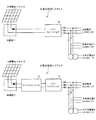
〔太陽光発電システム〕
まず、太陽光発電システムの全体構成について説明する。図1は、一般的な太陽光発電システムの全体構成を示す概略図である。図1の上部を参照して、この太陽光発電システム1は、太陽電池パネル10、接続箱11及びパワーコンディショナ(DC/ACコンディショナ)12等を備えており、太陽電池パネル10に蓄積された電力を商用電源(系統電源、非常用電源A,B)へ系統連係させる。接続箱11は、太陽電池パネル10の電力をパワーコンディショナ12へ出力するためのダイオードを備えている。パワーコンディショナ12は、太陽電池パネル10の発電を効率的に行うために、太陽電池パネル10の出力電圧を制御して最適な電力制御を実現するMPPT制御を行い、太陽電池パネル10からのDCの出力電圧をAC電圧に変換する。
〔Solar power system〕
First, the overall configuration of the photovoltaic power generation system will be described. FIG. 1 is a schematic diagram showing an overall configuration of a general photovoltaic power generation system. Referring to the upper part of FIG. 1, this solar
図1の下部を参照して、この太陽光発電システム2は、太陽電池パネル10、接続箱11、DC−DCコンバータ(DCチョッパと呼ばれることもある)13及びパワーコンディショナ14等を備えており、太陽光発電システム1と同様に、太陽電池パネル10に蓄積された電力を商用電源(系統電源、非常用電源A,B)へ系統連係させる。DC−DCコンバータ13は、太陽電池パネル10の発電を効率的に行うために、太陽電池パネル10の出力電圧を制御して最適な電力制御を実現するMPPT制御を行い、太陽電池パネル10からのDCの出力電圧を、系統連係する商用電源に見合ったDC電圧に昇圧変換する。パワーコンディショナ14は、パワーコンディショナ12と同じ処理を行う。
Referring to the lower part of FIG. 1, this photovoltaic
DC−DCコンバータ13は、太陽電池パネル10の出力電圧を商用電源に見合った電圧に変換するから、各種の太陽電池パネル10の出力電圧に対応すると共に、系統連係先の電圧にも容易に対応することができる。
Since the DC-
〔太陽電池パネルの発電基本特性〕
次に、太陽電池パネル10の発電基本特性について説明する。太陽電池パネル10の発電基本特性は、日射量特性、出力特性、分光感度・ダイオード特性等に分類され、これらの特性のうち出力特性は、PV特性と呼ばれる重要なパラメータである。太陽電池パネル10の発電基本特性は、太陽電池パネル10の種類及び日射量等により変動するので、一義的には定まらず、数値的取り扱いが複雑になる。
[Basic characteristics of solar panel power generation]
Next, basic power generation characteristics of the
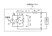
図7は、太陽電池パネル10の等価回路を示す図である。図7に示すように、太陽電池パネル10の等価回路は、電流源21、ダイオード22、抵抗(内部抵抗)23及び抵抗(配線抵抗)24により表記される。ダイオード22及び抵抗23は、それぞれ電流源21に並列に接続されており、抵抗24は、電流源21、ダイオード22及び抵抗23に直列に接続されている。この等価回路において、出力電流Iは、単位面積あたりの電流であり、その単位はA/cm2で表される。抵抗23の抵抗値はRrであり、その単位はΩ・cm2で表され、抵抗24の抵抗値はRsであり、その単位はΩ・cm2で表される。太陽電池パネル10の発生電圧Vpv及び出力電圧V0の単位はVで表されるから、負荷Zへ供給される出力電力の単位はW/cm2で表される。
FIG. 7 is a diagram showing an equivalent circuit of the
図7において、日射量に比例した起電力によって電流源21から発生する電流をIpvとすると、太陽電池パネル10の出力電流Iは、内部抵抗である抵抗23及びダイオード22の損失を考慮して、以下の式で表される。
[数1]
I=Ipv−Id−Ir=Ipv−Id−(V0+RsI)/Rr ・・・(1)
Idはダイオード22による損失電流であり、Irは抵抗23による損失電流である。尚、Ir=Vpv/Rr、Vpv=V0+RsI、V0=Vpv−RsIである。
In FIG. 7, when the current generated from the
[Equation 1]
I = Ipv-Id-Ir = Ipv-Id- (V0 + RsI) / Rr (1)
Id is a loss current due to the
前記式(1)から、日射量が多くなると、電流Ipvが増加して出力電流Iは増加するが、日射量が少なくなると、抵抗23の抵抗値が大きくなって出力電流Iは減少する。
From the equation (1), when the amount of solar radiation increases, the current Ipv increases and the output current I increases. However, when the amount of solar radiation decreases, the resistance value of the
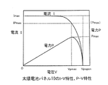
図8は、太陽電池パネル10のI−V特性、P−V特性を示す図である。図8において、横軸は太陽電池パネル10の出力電圧(電圧V、図7に示したV0に相当)を示し、縦軸は出力電流(電流I)及び出力電力(電力P)を示す。Pmaxは、電力Pの最大値であり、Vpmaxは、電力Pが最大のときの電圧Vの値であり、Vpopenは、開放電圧であり、そのときの電力Pは0である。Imaxは、電流Iの最大値であり、IPmaxは、電力Pが最大のときの電流Iの値である。
FIG. 8 is a diagram illustrating the IV characteristics and the PV characteristics of the
図8のP−V特性から、電圧Vが0からVpmaxまで上昇すると、電力Pはこれに比例して0からPmaxまで上昇し、電圧VがさらにVpmaxからVpopenまで上昇すると、電力PはPmaxから0まで下降することがわかる。また、I−V特性から、電圧Vが0からVpmaxよりも小さい所定値まで上昇すると、電流Iはやや減少するものの、ほぼ最大値Imaxを保ち、電圧VがさらにVpopenまで上昇すると、電流Iは0まで下降することがわかる。 From the PV characteristics of FIG. 8, when the voltage V increases from 0 to Vpmax, the power P increases in proportion to 0 to Pmax, and when the voltage V further increases from Vpmax to Vpopen, the power P increases from Pmax. It turns out that it falls to zero. Also, from the I-V characteristic, when the voltage V increases from 0 to a predetermined value smaller than Vpmax, the current I slightly decreases, but the maximum value Imax is maintained, and when the voltage V further increases to Vpopen, the current I is It turns out that it falls to zero.
〔山登り法〕
次に、MPPT制御の一例として知られている山登り法について説明する。図8に示した特性を有する太陽電池パネル10から電力を有効に取り出すには、一定の負荷の下で動作させる必要がある。山登り法には、太陽電池パネル10の出力電力を制御するための制御電圧に対するシフト量を固定にして、前回の制御電圧における出力電力と今回の制御電圧における出力電力とを比較し、その増減に応じてシフト方向を変えながらシフトを繰り返す制御を行う手法、及び、制御電圧のシフト量を固定にしないで、出力電圧の差分に比例したシフト量を決定して制御を行う手法(特許文献1)、出力電力の差分に比例したシフト量を決定して制御を行う手法等が提案されている。以下では、シフト量を固定にした場合の山登り法を例にして説明する。
[Mountain climbing method]
Next, a hill climbing method known as an example of MPPT control will be described. In order to effectively extract electric power from the
図9は、山登り法を説明する図である。図9において、横軸は、太陽電池パネル10の制御電圧を示し、縦軸は出力電力を示す。山登り法は、制御電圧を開放電圧V0付近から微少にシフト(減少)させる(シフト電圧ΔV毎に減少させる)ことで出力電力を増減させ、出力電力の傾向に応じて制御電圧のシフト方向を変えて、最大の出力電力の到達点(動作点(V10,P10))を検出するものである。
FIG. 9 is a diagram for explaining the mountain climbing method. In FIG. 9, the horizontal axis indicates the control voltage of the
図1に示した太陽光発電システム1において、パワーコンディショナ12に備えた制御部は、太陽電池パネル10の出力電力を取り込み、太陽電池パネル10の制御電圧を可変することで、出力電力が最大となる動作点を探索する。また、太陽光発電システム2において、DC−DCコンバータ13に備えた制御部は、太陽電池パネル10の出力電力を取り込み、太陽電池パネル10の制御電圧を可変することで、出力電力が最大となる動作点を探索する。
In the photovoltaic
図9に戻って、制御電圧がV0からV9までの間では、出力電力はP0からP9まで徐々に増加する。そして、制御電圧がV10になると、出力電力は最大のP10となり、さらに制御電圧をΔVだけシフトして制御電圧がV11になると、出力電力P11は前回の出力電力P10よりも減少する。このような出力電力の増加から減少へ転じる判別がなされたときに、最大電力の動作点が検出され、シフト方向を反転させ、これまで制御電圧をΔV毎に下げてきたのをΔV毎に上げるようにして、制御電圧を元のV10へ戻す。その結果、制御電圧V10における出力電力P10は、前回の出力電力P11よりも増加するから、シフト方向は維持され、制御電圧はV9へ戻ることになる。そうすると、出力電力P9は前回の制御電圧V10で得られた出力電力P10よりも減少するから、シフト方向を反転させる。 Returning to FIG. 9, when the control voltage is between V0 and V9, the output power gradually increases from P0 to P9. When the control voltage becomes V10, the output power becomes the maximum P10, and when the control voltage is further shifted by ΔV and the control voltage becomes V11, the output power P11 decreases from the previous output power P10. When it is determined that the output power increases to decrease, the operating point of the maximum power is detected, the shift direction is reversed, and the control voltage has been decreased for every ΔV until it is increased for every ΔV. Thus, the control voltage is returned to the original V10. As a result, the output power P10 at the control voltage V10 increases from the previous output power P11, so the shift direction is maintained and the control voltage returns to V9. Then, since the output power P9 is smaller than the output power P10 obtained with the previous control voltage V10, the shift direction is reversed.
このように、制御電圧及び出力電力の動作点は、出力電力が最大となる動作点(V10,P10)を挟んで前後への移動、すなわち動作点(V9,P9)及び動作点(V11,P11)の移動を繰り返すことになる。これにより、出力電力が最大となる動作点(V10,P10)における制御電圧V10を維持することができる。 As described above, the operating points of the control voltage and the output power are moved back and forth across the operating point (V10, P10) where the output power is maximum, that is, the operating point (V9, P9) and the operating point (V11, P11). ) Will be repeated. Thereby, the control voltage V10 at the operating point (V10, P10) at which the output power becomes maximum can be maintained.
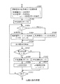
〔山登り法による処理〕
次に、山登り法の処理について説明する。図10は、山登り法の処理を示すフローチャートである。山登り法の処理は、図1に示した太陽光発電システム1のパワーコンディショナ12が備える制御部及び太陽光発電システム2のDC−DCコンバータ13が備える制御部により行われる。
[Treatment by hill climbing method]
Next, the hill climbing process will be described. FIG. 10 is a flowchart showing processing of the hill climbing method. The hill-climbing process is performed by a control unit included in the
まず、パワーコンディショナ12及びDC−DCコンバータ13の制御部は、開放電圧V0を基準とした初期処理を行う(ステップS1001)。具体的には、制御部は、MPPT制御の開始の制御電圧Vとして開放電圧V0を設定し(V=V0)、太陽電池パネル10から、制御電圧V0に応じた出力電力P0を取り込み(P=P0)、制御電圧Vのシフト方向を定めるパラメータcとして、反時計回りを示すデータを設定する(c=−1)。パラメータc=−1は、制御電圧Vを下げる方向へシフトさせることを意味し、パラメータc=1は、制御電圧Vを上げる方向へシフトさせることを意味する。そして、制御部は、基準電力PPとして出力電力P0を設定する(PP=P0、ステップS1002)。したがって、MPPT制御を開放電圧V0からスタートする場合はc=−1の設定になる。
First, the control units of the
制御部は、パラメータcが1(時計回り)であるか−1(反時計回り)であるかを判定する(ステップS1003)。制御部は、ステップS1003において、c=−1(反時計回り)であると判定した場合(ステップS1003:c=−1)、制御電圧Vを下げる方向へシフトさせるために、前回の制御電圧Vからシフト電圧ΔVを減算して新たな今回の制御電圧Vを設定する(V(今回)=V(前回)−ΔV、ステップS1004)。尚、シフト電圧ΔVは予め設定されているものとする。 The control unit determines whether the parameter c is 1 (clockwise) or -1 (counterclockwise) (step S1003). When it is determined in step S1003 that c = −1 (counterclockwise) (step S1003: c = −1), the control unit shifts the control voltage V in the direction of decreasing the previous control voltage V. Is subtracted from the shift voltage ΔV to set a new control voltage V this time (V (current) = V (previous) −ΔV, step S1004). Note that the shift voltage ΔV is set in advance.
図9を参照して、1回目の処理ではc=−1であるから、ステップS1004にて新たな今回の制御電圧Vとして制御電圧V1=V0−ΔVが設定される。これにより、新たな今回の制御電圧V1は、初期の制御電圧V0からΔVだけ引き下げられる。このステップS1004の処理は、最大の出力電力P10が検出されるまで繰り返して行われ、その繰り返しの回数をNとすると、ステップS1004のN回目(N=1〜10)の処理では、制御電圧V=V0−ΔV×Nが設定される。 Referring to FIG. 9, since c = −1 in the first process, control voltage V1 = V0−ΔV is set as new current control voltage V in step S1004. As a result, the new current control voltage V1 is lowered by ΔV from the initial control voltage V0. The process in step S1004 is repeatedly performed until the maximum output power P10 is detected. If the number of repetitions is N, the control voltage V is determined in the Nth process (N = 1 to 10) in step S1004. = V0−ΔV × N is set.
図10に戻って、制御部は、ステップS1003において、c=1(時計回り)であると判定した場合(ステップS1003:c=1)、制御電圧Vを上げる方向へシフトさせるために、前回の制御電圧Vにシフト電圧ΔVを加算して新たな今回の制御電圧Vを設定する(V(今回)=V(前回)+ΔV、ステップS1005)。 Returning to FIG. 10, when it is determined in step S1003 that c = 1 (clockwise) (step S1003: c = 1), in order to shift the control voltage V in the increasing direction, the control unit The shift voltage ΔV is added to the control voltage V to set a new current control voltage V (V (current) = V (previous) + ΔV, step S1005).
制御部は、太陽電池パネル10から、新たな今回の制御電圧Vに応じた出力電力Pを取り込む(ステップS1006)。ステップS1006の1回目の処理では、制御電圧V1に応じた出力電力P1が取り込まれる。 The control unit takes in the output power P corresponding to the new current control voltage V from the solar cell panel 10 (step S1006). In the first process of step S1006, output power P1 corresponding to the control voltage V1 is captured.
制御部は、ステップS1006にて取り込んだ出力電力P(今回の出力電力P)と基準電力PP(前回の出力電力P(前回に取り込んだ出力電力P))とを比較し、出力電力Pが基準電力PPよりも大きいか否かを判定する(ステップS1007)。制御部は、ステップS1007において、出力電力Pが基準電力PPよりも大きいと判定した場合(ステップS1007:Y)、基準電力PPとして出力電力Pを設定し、基準電力PPを更新する(PP=P、ステップS1008)。そして、制御部は、制御電圧Vのシフト方向を定めるパラメータcをそのままに維持し(ステップS1009)、ステップS1012へ移行する。尚、ステップS1008にて設定された基準電力PPは、ステップS1007の比較処理において、前回の出力電力Pとして用いられる。 The control unit compares the output power P (current output power P) captured in step S1006 with the reference power PP (previous output power P (previous output power P)), and the output power P is the reference. It is determined whether or not it is greater than the power PP (step S1007). When it is determined in step S1007 that the output power P is larger than the reference power PP (step S1007: Y), the control unit sets the output power P as the reference power PP and updates the reference power PP (PP = P Step S1008). Then, the control unit maintains the parameter c that determines the shift direction of the control voltage V as it is (step S1009), and proceeds to step S1012. The reference power PP set in step S1008 is used as the previous output power P in the comparison process in step S1007.
図9を参照して、出力電力P0,・・・,P10は、制御電圧V0からV10まで変化するに従って増加する。これにより、制御電圧V0〜V10及び出力電力P0〜P10の領域では、ステップS1007にて出力電力Pは基準電力PPよりも大きいと判定され、ステップS1008にて基準電力PPは更新され、ステップS1009にてパラメータcは−1に維持される。これにより、制御電圧Vは、V0からV10までの間でシフト電圧ΔV毎に継続して下げられ、これに伴って出力電力Pは、P0からP10まで増加する。 Referring to FIG. 9, output powers P0,..., P10 increase as they change from control voltage V0 to V10. Thereby, in the region of the control voltages V0 to V10 and the output powers P0 to P10, it is determined in step S1007 that the output power P is larger than the reference power PP, the reference power PP is updated in step S1008, and the process proceeds to step S1009. Parameter c is maintained at -1. As a result, the control voltage V is continuously decreased for each shift voltage ΔV between V0 and V10, and the output power P increases from P0 to P10 accordingly.
図10に戻って、制御部は、ステップS1007において、出力電力Pが基準電力PPよりも大きくない(出力電力Pが基準電力PP以下である)と判定した場合(ステップS1007:N)、基準電力PPとして出力電力Pを設定し、基準電力PPを更新する(PP=P、ステップS1010)。そして、制御部は、パラメータcの極性を反転し(c=c×(−1)、ステップS1011)、ステップS1012へ移行する。パラメータcの極性を反転することにより、反対のシフト方向が設定される。尚、ステップS1010にて設定された基準電力PPは、ステップS1007の比較処理において、前回の出力電力Pとして用いられる。 Returning to FIG. 10, when the control unit determines in step S1007 that the output power P is not greater than the reference power PP (the output power P is equal to or less than the reference power PP) (step S1007: N), the reference power The output power P is set as PP, and the reference power PP is updated (PP = P, step S1010). Then, the control unit reverses the polarity of the parameter c (c = c × (−1), step S1011), and proceeds to step S1012. By inverting the polarity of parameter c, the opposite shift direction is set. The reference power PP set in step S1010 is used as the previous output power P in the comparison process in step S1007.
具体的には、制御部は、パラメータcが−1(反時計回り)の場合、パラメータc=1(時計回り)に設定し、パラメータcが1(時計回り)の場合、パラメータc=−1(反時計回り)に設定する。パラメータc=1(時計回り)に設定されることにより、ステップS1005において、制御電圧Vはシフト電圧ΔV分上がる方向へシフトする。また、パラメータc=−1(反時計回り)に設定されることにより、ステップS1004において、制御電圧Vは、シフト電圧ΔV分下がる方向へシフトする。 Specifically, the control unit sets parameter c = 1 (clockwise) when parameter c is −1 (counterclockwise), and parameter c = −1 when parameter c is 1 (clockwise). Set to (counterclockwise). By setting parameter c = 1 (clockwise), in step S1005, the control voltage V is shifted in the direction of increasing by the shift voltage ΔV. Further, by setting the parameter c = −1 (counterclockwise), the control voltage V is shifted in the direction of decreasing by the shift voltage ΔV in step S1004.
図9を参照して、出力電力P10,P11は、制御電圧V10からV11まで変化するに従って減少する。これにより、制御電圧V10,V11及び出力電力P10,P11の領域では、ステップS1007にて出力電力P11は基準電力PP=P10よりも大きくないと判定され、ステップS1010にて基準電力PPはP11に更新され、ステップS1011にてパラメータcの極性は反転し、c=1に設定される。これにより、制御電圧Vは、ステップS1005において、V11からV10に上げられ、これに伴って出力電力Pは、P11からP10に増加する。 Referring to FIG. 9, output powers P10 and P11 decrease as they change from control voltage V10 to V11. Thereby, in the region of the control voltages V10, V11 and the output powers P10, P11, it is determined in step S1007 that the output power P11 is not larger than the reference power PP = P10, and the reference power PP is updated to P11 in step S1010. In step S1011, the polarity of the parameter c is inverted and c = 1 is set. As a result, the control voltage V is increased from V11 to V10 in step S1005, and the output power P increases from P11 to P10 accordingly.
そして、ステップS1007にて出力電力P10は基準電力PP=P11よりも大きいと判定され、ステップS1008にて基準電力PPはP10に更新され、ステップS1009にてパラメータcは1に維持される。これにより、制御電圧Vは、ステップS1005において、V10からV9に上げられ、これに伴って出力電力Pは、P10からP9に減少する。 In step S1007, it is determined that the output power P10 is larger than the reference power PP = P11, the reference power PP is updated to P10 in step S1008, and the parameter c is maintained at 1 in step S1009. As a result, the control voltage V is increased from V10 to V9 in step S1005, and the output power P is decreased from P10 to P9 accordingly.
そして、ステップS1007にて出力電力P9は基準電力PP=P10よりも大きくないと判定され、ステップS1010にて基準電力PPはP9に更新され、ステップS1011にてパラメータcの極性は反転し、c=−1に設定される。これにより、制御電圧Vは、ステップS1004において、V9からV10に下げられ、これに伴って出力電力Pは、P9からP10に増加する。 In step S1007, it is determined that the output power P9 is not greater than the reference power PP = P10. In step S1010, the reference power PP is updated to P9. In step S1011, the polarity of the parameter c is inverted. Set to -1. Thereby, the control voltage V is lowered from V9 to V10 in step S1004, and the output power P is increased from P9 to P10 accordingly.
このように、出力電力Pが最大の出力電力P10に到達するまでの間、動作点は(V0,P0)から(V10,P10)まで移行し、その後、最大の出力電力P10である動作点(V10,P10)を中心に、動作点(V11,P11)と動作点(V9,P9)との間の移行を繰り返す。 Thus, until the output power P reaches the maximum output power P10, the operating point shifts from (V0, P0) to (V10, P10), and then the operating point at which the maximum output power P10 is ( The transition between the operating point (V11, P11) and the operating point (V9, P9) is repeated centering on V10, P10).
これにより、最大の出力電力の動作点(V10,P10)を中心にして制御電圧Vは維持され、最高の効率で太陽電池パネル10の発電を維持することができる。
Thereby, the control voltage V is maintained around the operating point (V10, P10) of the maximum output power, and the power generation of the
図10に戻って、制御部は、処理を終了させるための所定の条件を満たさない限り、ステップS1003へ移行し、所定の条件(夜間停止等)を満たす場合、処理を終了させる(ステップS1012)。 Returning to FIG. 10, the control unit proceeds to step S1003 unless the predetermined condition for ending the process is satisfied, and ends the process when the predetermined condition (night stop, etc.) is satisfied (step S1012). .
従来の山登り法では、図10に示したように、開放電圧V0を基準とした値に制御電圧Vを設定し、そこからMPPT制御を開始しており、最大の出力電力の動作点に到達するまでに時間を要してしまい、ロスが大きいという問題があった。 In the conventional hill-climbing method, as shown in FIG. 10, the control voltage V is set to a value based on the open circuit voltage V0, and MPPT control is started therefrom, and the operating point of the maximum output power is reached. There was a problem that it took a long time to finish and the loss was large.
また、前述の山登り法だけに限らず多くのMPPT制御においては、天候または日陰等により日射量が変化すると、MPPT制御の精度が低下するという問題があった。つまり、制御電圧Vの変化に伴う出力電力Pの変化を監視し、最大の出力電力Pの動作点を検出するという本来のMPPT制御の有効性が、日射量が変化するという外乱によって、損なわれてしまうという問題があった。例えば、日射量が少ない場合には信号レベルが大幅に低下することから、その検出精度は低下し、結果として最大の出力電力Pの動作点を検出することが難しくなる。 In addition to the above-described hill-climbing method, many MPPT controls have a problem that the accuracy of MPPT control is reduced when the amount of solar radiation changes due to weather or shade. In other words, the effectiveness of the original MPPT control of monitoring the change of the output power P accompanying the change of the control voltage V and detecting the operating point of the maximum output power P is impaired by the disturbance that the amount of solar radiation changes. There was a problem that. For example, when the amount of solar radiation is small, the signal level is greatly lowered, so that the detection accuracy is lowered, and as a result, it becomes difficult to detect the operating point of the maximum output power P.
そこで、本発明は前記課題を解決するためになされたものであり、その目的は、MPPT制御を効率的に行うことが可能な太陽光発電装置及び太陽光発電制御方法を提供することにある。 Therefore, the present invention has been made to solve the above-described problems, and an object thereof is to provide a solar power generation apparatus and a solar power generation control method capable of efficiently performing MPPT control.
前記目的を達成するために、請求項1の太陽光発電装置は、太陽電池パネルの制御電圧をシフトさせ、前記太陽電池パネルの出力電力が最大となる動作点を追従制御する制御部を備えた太陽光発電装置において、前記制御部が、前記追従制御の開始時に、前記制御電圧として前記太陽電池パネルの所定の定格電圧を設定し、前記制御電圧に応じた出力電力を定格電圧時出力電力として取り込み、前記定格電圧時出力電力が前記太陽電池パネルの所定の定格出力よりも小さいと判定した場合、前記制御電圧のシフト方向を下げる方向に設定し、前記定格電圧時出力電力が前記所定の定格出力よりも小さくないと判定した場合、前記制御電圧のシフト方向を上げる方向に設定する初期設定手段と、前記制御電圧をシフトさせて新たな制御電圧を設定し、前記新たな制御電圧に応じた出力電力を取り込み、前記取り込んだ今回の出力電力と前回の出力電力とを比較し、今回の出力電力が前回の出力電力よりも大きいと判定した場合、前記シフト方向を維持し、今回の出力電力が前回の出力電力よりも大きくないと判定した場合、前記シフトさせた方向とは反対のシフト方向を設定する制御手段と、を備え、前記制御手段が、前記初期設定手段により設定されたシフト方向の新たな制御電圧を設定し、当該制御手段が設定したシフト方向の新たな制御電圧を順次設定し、前記出力電力が最大となる動作点を追従制御する、ことを特徴とする。
In order to achieve the object, the photovoltaic power generation apparatus according to
また、請求項2の太陽光発電装置は、太陽電池パネルの制御電圧をシフトさせ、前記太陽電池パネルの出力電力が最大となる動作点を追従制御する制御部を備えた太陽光発電装置において、前記制御部が、前記追従制御の開始時に、前記制御電圧として前記太陽電池パネルの所定の定格電圧を設定し、前記制御電圧に応じた出力電力を定格電圧時出力電力として取り込み、前記定格電圧時出力電力と前記太陽電池パネルの所定の定格出力との比較結果に基づいて、前記制御電圧のシフト方向を設定する初期設定手段と、前記制御電圧をシフトさせて新たな制御電圧を設定し、前記新たな制御電圧に応じた出力電力を取り込み、前記取り込んだ今回の出力電力と前回の出力電力とを比較し、今回の出力電力が前回の出力電力よりも大きいと判定した場合、前記シフト方向を維持し、今回の出力電力が前回の出力電力よりも大きくないと判定した場合、前記シフトさせた方向とは反対のシフト方向を設定する制御手段と、を備え、前記制御手段が、前記初期設定手段により設定されたシフト方向の新たな制御電圧を設定し、当該制御手段が設定したシフト方向の新たな制御電圧を順次設定し、前記出力電力が最大となる動作点を追従制御し、前記制御部が、さらに、回帰判定手段を備え、前記回帰判定手段が、前記定格電圧時出力電力と前記制御手段により取り込まれた今回の出力電力とを比較し、前記定格電圧時出力電力が今回の出力電力よりも小さいと判定した場合、回帰無しを判断し、前記定格電圧時出力電力が今回の出力電力よりも小さくないと判定した場合、回帰有りを判断し、前記回帰無しが判断された場合、前記制御手段が、前記新たな制御電圧の設定、前記出力電力の取り込み及び前記シフト方向の設定を行い、前記回帰有りが判断された場合、前記初期設定手段が、前記追従制御の開始時と同じ処理を再度行い、前記制御手段が、前記新たな制御電圧の設定、前記出力電力の取り込み及び前記シフト方向の設定を行う、ことを特徴とする。
Moreover, the solar power generation device according to
また、請求項3の太陽光発電装置は、太陽電池パネルの制御電圧をシフトさせ、前記太陽電池パネルの出力電力が最大となる動作点を追従制御する制御部を備えた太陽光発電装置において、前記制御部が、前記追従制御の開始時に、前記制御電圧として前記太陽電池パネルの所定の定格電圧を設定し、前記制御電圧に応じた出力電力を定格電圧時出力電力として取り込み、前記定格電圧時出力電力と前記太陽電池パネルの所定の定格出力との比較結果に基づいて、前記制御電圧のシフト方向を設定する初期設定手段と、前記制御電圧をシフトさせて新たな制御電圧を設定し、前記新たな制御電圧に応じた出力電力を取り込み、前記取り込んだ今回の出力電力と前回の出力電力とを比較し、今回の出力電力が前回の出力電力よりも大きいと判定した場合、前記シフト方向を維持し、今回の出力電力が前回の出力電力よりも大きくないと判定した場合、前記シフトさせた方向とは反対のシフト方向を設定する制御手段と、を備え、前記制御手段が、前記初期設定手段により設定されたシフト方向の新たな制御電圧を設定し、当該制御手段が設定したシフト方向の新たな制御電圧を順次設定し、前記出力電力が最大となる動作点を追従制御し、前記制御部が、さらに、回帰判定手段を備え、前記回帰判定手段が、前記制御手段により新たな制御電圧が設定されたときのシフト回数と所定の制限値とを比較し、前記シフト回数が所定の制限値よりも小さいと判定した場合、回帰無しを判断し、前記シフト回数が所定の制限値よりも小さくないと判定した場合、回帰有りを判断し、前記回帰無しが判断された場合、前記制御手段が、前記新たな制御電圧の設定、前記出力電圧の取り込み及び前記シフト方向の設定を行い、前記回帰有りが判断された場合、前記初期設定手段が、前記追従制御の開始時と同じ処理を再度行い、前記制御手段が、前記新たな制御電圧の設定、前記出力電圧の取り込み及び前記シフト方向の設定を行う、ことを特徴とする。
Further, the photovoltaic power generation apparatus according to
また、請求項4の太陽光発電装置は、請求項1から3までのいずれか一項に記載の太陽光発電装置において、前記太陽電池パネルの出力電力を3相の電力に変換するパワーコンディショナを備え、当該パワーコンディショナが前記制御部を備えることを特徴とする。
Moreover, the solar power generation device of Claim 4 is a power conditioner which converts the output electric power of the said solar cell panel into three-phase electric power in the solar power generation device as described in any one of
また、請求項5の太陽光発電装置は、請求項1から3までのいずれか一項に記載の太陽光発電装置において、前記太陽電池パネルにより出力された電圧を所定の電圧に変換するDC−DCコンバータと、前記DC−DCコンバータからの出力電力を3相の電力に変換するパワーコンディショナと、を備え、当該DC−DCコンバータが前記制御部を備えることを特徴とする。
Moreover, the solar power generation device of Claim 5 is DC- which converts the voltage output by the said solar cell panel into a predetermined voltage in the solar power generation device as described in any one of
また、請求項6の太陽光発電装置は、請求項1から5までのいずれか一項に記載の太陽光発電装置において、前記制御電圧をシフトさせるシフト量を、固定値、前記太陽電池パネルの出力電力に応じた値、または前記太陽電池パネルの出力電圧に応じた値とする、ことを特徴とする。 Moreover, the photovoltaic power generation apparatus of Claim 6 WHEREIN: The photovoltaic power generation apparatus as described in any one of Claim 1-5 WHEREIN: The shift amount which shifts the said control voltage is set to a fixed value, and the said solar cell panel. A value corresponding to the output power or a value corresponding to the output voltage of the solar cell panel is used.
さらに、請求項7の太陽光発電制御方法は、太陽電池パネルの制御電圧をシフトさせ、前記太陽電池パネルの出力電力が最大となる動作点を追従制御する太陽光発電制御方法において、前記追従制御の開始時に、前記制御電圧として前記太陽電池パネルの所定の定格電圧を設定し、前記制御電圧に応じた出力電力を定格電圧時出力電力として取り込み、前記定格電圧時出力電力と前記太陽電池パネルの所定の定格出力との比較結果に基づいて、前記制御電圧のシフト方向を設定する第1のステップと、前記第1のステップにて設定したシフト方向に前記制御電圧をシフトさせて新たな制御電圧を設定する第2のステップと、前記新たな制御電圧に応じた出力電力を取り込み、前記取り込んだ今回の出力電力と前回の出力電力とを比較し、今回の出力電力が前回の出力電力よりも大きいと判定した場合、前記シフト方向を維持し、今回の出力電力が前回の出力電力よりも大きくないと判定した場合、前記シフトさせた方向とは反対のシフト方向を設定する第3のステップと、前記第3のステップにて設定したシフト方向に前記制御電圧をシフトさせて新たな制御電圧を設定する第4のステップと、前記第3のステップと前記第4のステップとを繰り返す第5のステップと、を有し、前記第5のステップは、さらに、前記定格電圧時出力電力と前記今回の出力電力とを比較すると共に、前記第4のステップにて新たな制御電圧を設定したときのシフト回数と所定の制限値とを比較し、前記定格電圧時出力電力が今回の出力電力よりも小さくないと判定した場合、または、前記シフト回数が所定の制限値よりも小さくないと判定した場合、前記第1のステップにおける追従制御の開始時と同じ処理を再度行う、ことを特徴とする。 Furthermore, the photovoltaic power generation control method according to claim 7 is a photovoltaic power generation control method in which the control voltage of the solar cell panel is shifted and the operating point at which the output power of the solar cell panel is maximized is controlled to follow. At the time of starting, a predetermined rated voltage of the solar cell panel is set as the control voltage, the output power corresponding to the control voltage is taken as the output power at the rated voltage, the output power at the rated voltage and the solar cell panel Based on a comparison result with a predetermined rated output, a first step of setting the shift direction of the control voltage, and a new control voltage by shifting the control voltage in the shift direction set in the first step The second step of setting the output power, the output power corresponding to the new control voltage is captured, and the captured current output power is compared with the previous output power. When it is determined that the output power is greater than the previous output power, the shift direction is maintained, and when it is determined that the current output power is not greater than the previous output power, the shift opposite to the shifted direction is performed. A third step of setting a direction, a fourth step of setting a new control voltage by shifting the control voltage in the shift direction set in the third step, the third step, and the second step A fifth step that repeats the step 4 and the fifth step further compares the output power at the rated voltage with the current output power, and in the fourth step When the number of shifts when a new control voltage is set is compared with a predetermined limit value and it is determined that the output power at the rated voltage is not smaller than the current output power, or the number of shifts If it is determined that not smaller than the predetermined limit value, performs the same processing as the beginning of the follow-up control in the first step again, characterized in that.
以上のように、本発明によれば、最大の出力電力の動作点まで短時間に到達することができ、MPPT制御を効率的に行うことが可能となる。 As described above, according to the present invention, the operating point of the maximum output power can be reached in a short time, and MPPT control can be performed efficiently.
以下、本発明を実施するための形態について図面を用いて詳細に説明する。
〔本発明の概要〕
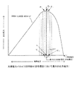
まず、本発明の概要について説明する。図11は、日射量が1000W/m2のときの太陽電池パネル10の特性Aを示す図である。図12は、日射量が1000W/m2を上回るときの太陽電池パネル10の特性B、及び日射量が1000W/m2を下回るときの太陽電池パネル10の特性Cを示す図である。図11及び図12において、横軸は制御電圧を示し、縦軸は出力電力を示す。
Hereinafter, embodiments for carrying out the present invention will be described in detail with reference to the drawings.
[Outline of the Invention]
First, an outline of the present invention will be described. FIG. 11 is a diagram showing the characteristic A of the
図11の特性A(日射量が1000W/m2のときの特性)は、太陽電池パネル10の最大出力制御電圧(定格電圧)において、最大の出力電力となる特性を示している。つまり、制御電圧Vが最大出力制御電圧(定格電圧)V0のときに、出力電力P0は最大になっている。
A characteristic A (characteristic when the amount of solar radiation is 1000 W / m 2 ) in FIG. 11 indicates a characteristic that provides the maximum output power at the maximum output control voltage (rated voltage) of the
図12の特性B(日射量が1000W/m2を上回るときの特性)は、発電電力(定格電圧のときの出力電力)が太陽電池パネル10の定格出力よりも大きくなり、最大の出力電力及びそのときの制御電圧の動作点が、特性Aに示した最大の出力電圧及びそのときの制御電圧(定格電圧)の動作点よりも上昇する特性を示している。つまり、特性Bでは、制御電圧V-2のときに出力電力P-2は最大になっている。
Characteristic B in FIG. 12 (characteristic when the amount of solar radiation exceeds 1000 W / m 2 ) is such that the generated power (output power at the rated voltage) is larger than the rated output of the
図12の特性C(日射量が1000W/m2を下回るときの特性)は、発電電力(定格電圧のときの出力電力)は太陽電池パネル10の定格出力よりも小さくなり、最大の出力電力及びそのときの制御電圧の動作点が、特性Aに示した最大の出力電圧及びそのときの制御電圧(定格電圧)の動作点よりも下降する特性を示している。つまり、特性Cでは、制御電圧V4のときに出力電力P4は最大になっている。
Characteristic C in FIG. 12 (characteristic when the amount of solar radiation is less than 1000 W / m 2 ) indicates that the generated power (output power at the rated voltage) is smaller than the rated output of the
このように、日射量が異なる太陽電池パネル10において、日射量が多くなり、それに伴って最大の出力電力が大きくなると、そのときの制御電圧も大きくなり、一方で、日射量が少なくなり、それに伴って最大の出力電力が小さくなると、そのときの制御電圧も小さくなる。日射量は天候に大きく左右され、曇り空または日陰等の影響を大きく受けて、太陽電池パネル10の出力電力は大きく変動する。しかしながら、図11及び図12から、日射量が異なる場合であって、最大の出力電力は、制御電圧が定格電圧のときの出力電力の近くに存在し、最大の出力電力のときの制御電圧は、定格電圧の近くに存在する。
Thus, in the
そこで、本発明は、定格電圧を基準とした値に制御電圧を設定し、そこからMPPT制御を開始することを特徴とする。これにより、最大の出力電力の動作点まで短時間に到達することができるから、無駄な電力消費をなくし、MPPT制御を効率的に行うことが可能となる。 Therefore, the present invention is characterized in that the control voltage is set to a value based on the rated voltage, and MPPT control is started therefrom. As a result, the operating point of the maximum output power can be reached in a short time, so that unnecessary power consumption can be eliminated and MPPT control can be performed efficiently.
また、本発明は、太陽電池パネル10から取り込んだ今回の出力電力が定格電圧のときの出力電力以下になった場合、または、制御電圧のシフト回数が所定数以上になった場合、MPPT制御が不能になったと判断し、制御電圧を初期の電圧に設定する、すなわち定格電圧を基準とした値に制御電圧を設定することで、MPPT制御を再スタートさせることを特徴とする。これにより、天候または日陰等により日射量が変化し、MPPT制御が不能になった場合、MPPT制御を初期に戻すから、制御不能状態から脱出すると共に、制御不能時の無駄な電力消費をなくすことができ、MPPT制御を効率的に行うことが可能となる。
Further, in the present invention, when the current output power taken in from the
〔パワーコンディショナ〕
次に、図1に示した太陽光発電システム1において、本発明の実施形態による太陽光発電装置について説明する。太陽光発電システム1における太陽光発電装置はパワーコンディショナ12であり、MPPT制御を行う制御部を備えている。
[Power conditioner]
Next, in the photovoltaic
図2は、パワーコンディショナ12の構成を示すブロック図である。このパワーコンディショナ12は、MPPT制御機能部31、電流検出器32、電圧検出器33、電流検出器35、電気角検出器36、電流FB(FeedBack:フィードバック)3相/2相演算器37、演算器38、電流指令2相/3相演算器39、PWM(Pulse Width Modulation:パルス幅変調)制御器40及びパワー変換器41を備えている。図2には本発明と直接関連する構成部のみを示してあり、本発明と直接関連しない構成部は省略してある。
FIG. 2 is a block diagram showing the configuration of the
MPPT制御機能部31は、太陽電池パネル10の最大電力の動作点を追従して制御するMPPT制御である最大電力点追従制御を行うために、太陽電池パネル10の出力電圧及び出力電流を入力して出力電力を算出し、制御電圧を設定し、制御電圧と太陽電池パネル10の出力電圧との電圧偏差を出力する。具体的には、MPPT制御機能部31は、前述のとおり、定格電圧を基準とした値に制御電圧を設定し、そこからMPPT制御を開始すると共に、所定の場合にMPPT制御が不能になったと判定し、制御電圧を、定格電圧を基準とした初期の値に設定することで、MPPT制御を再スタートさせる。MPPT制御機能部31の詳細については後述する。
The MPPT
電流検出器32は、太陽電池パネル10から接続箱11を介して、太陽電池パネル10の出力電流を検出する。電流検出器32により検出された太陽電池パネル10の出力電流は、電力演算のためにMPPT制御機能部31へ電流FBとして入力される。
The
電圧検出器33は、太陽電池パネル10から接続箱11を介して、太陽電池パネル10の出力電圧を検出する。電圧検出器33により検出された太陽電池パネル10の出力電圧は、電力演算のためにMPPT制御機能部31へ電圧FBとして入力される。
The
電流検出器35は、パワー変換器41から系統電源等へ電力が供給される際の、3相の交流電流のそれぞれを電流FBとして検出する。電流検出器35により検出されたそれぞれの電流FBは、電流FB3相/2相演算器37へ入力される。
The
電気角検出器36は、パワー変換器41から系統電源等へ電力が供給される際の、3相の交流電圧における相間電圧を入力する。そして、電気角検出器36は、予め設定されたサインテーブルを用いて、入力した相間電圧のAC信号を静止座標系及び回転座標系で表す電圧ベクトルに変換して電気角を検出し、電気角を電流FB3相/2相演算器37及び電流指令2相/3相演算器39に出力する。
The
電流FB3相/2相演算器37は、電流検出器35から各相の電流FBを入力すると共に、電気角検出器36から電気角を入力し、各相の電流FB及び電気角に基づいて、3相の電流FBから2相の電流FBへの座標変換を行い、d軸電流FB及びq軸電流FBを生成する。そして、電流FB3相/2相演算器37は、d軸電流FB(Id)を電流指令2相/3相演算器39に出力し、q軸電流FBを演算器38に出力する。
The current FB 3-phase / 2-
演算器38は、電流FB3相/2相演算器37からq軸電流FBを入力すると共に、MPPT制御機能部31から電圧偏差を入力し、電圧偏差をq軸電流FBに加算し、加算結果のq軸電流FB(Iq)を電流指令2相/3相演算器39に出力する。
The
電流指令2相/3相演算器39は、演算器38から加算結果のq軸電流FB(Iq)を、電流FB3相/2相演算器37からd軸電流FB(Id)を、電気角検出器36から電気角をそれぞれ入力する。そして、電流指令2相/3相演算器39は、2相のq軸電流FB(Iq)及びd軸電流FB(Id)並びに電気角に基づいて、2相の電流指令から3相の電圧指令への座標変換を行い、3相の電圧指令を生成してPWM制御器40に出力する。
The current command 2-phase / 3-
PWM制御器40は、電流指令2相/3相演算器39から3相の電圧指令を入力し、入力した3相の電圧指令と、図示しない発振器にて発生する信号、例えば三角波信号等とを図示しないコンパレータに入力し、PWM信号を生成してパワー変換器41に出力する。パワー変換器41は、PWM制御器40からPWM信号を入力し、AC/DCの電力変換を行う。
The
これにより、電圧FBである太陽電池パネル10の出力電圧と、MPPT制御機能部31により設定された制御電圧との間の偏差が0になるように制御が行われ、太陽電池パネル10からのDCの出力電力がACの電力に変換され、ACの電力が系統電源等へ供給される。
Thereby, control is performed so that the deviation between the output voltage of the
〔DC−DCコンバータ〕
次に、図1に示した太陽光発電システム2において、本発明の実施形態による太陽光発電装置について説明する。太陽光発電システム2における太陽光発電装置は、DC−DCコンバータ13及びパワーコンディショナ14であり、DC−DCコンバータ13は、MPPT制御を行う制御部を備えている。以下、DC−DCコンバータ13について説明する。
[DC-DC converter]
Next, in the photovoltaic
図3は、DC−DCコンバータ13の構成を示すブロック図である。このDC−DCコンバータ13は、MPPT制御機能部51、電流検出器52、電圧検出器53、電圧制御器55、電流検出器56、演算器57、電流制御器58、PWM制御器59及びパワー変換器60を備えている。尚、図3には本発明と直接関連する構成部のみを示してあり、本発明と直接関連しない構成部は省略してある。
FIG. 3 is a block diagram showing the configuration of the DC-
MPPT制御機能部51は、図2に示したMPPT制御機能部31と同様に、太陽電池パネル10の最大電力の動作点を追従して制御するMPPT制御である最大電力点追従制御を行うために、太陽電池パネル10の出力電圧及び出力電流を入力して出力電力を算出し、制御電圧を設定し、制御電圧と太陽電池パネル10の出力電圧との電圧偏差を出力する。具体的には、MPPT制御機能部51は、前述のとおり、定格電圧を基準とした値に制御電圧を設定し、そこからMPPT制御を開始すると共に、所定の場合にMPPT制御が不能になったと判定し、制御電圧を、定格電圧を基準とした初期の値に設定することで、MPPT制御を再スタートさせる。MPPT制御機能部51の詳細については後述する。
The MPPT
電流検出器52は、太陽電池パネル10から接続箱11を介して、太陽電池パネル10の出力電流を検出する。電流検出器52により検出された太陽電池パネル10の出力電流は、電力演算のためにMPPT制御機能部51へ電流FBとして入力される。
The
電圧検出器53は、太陽電池パネル10から接続箱11を介して、太陽電池パネル10の出力電圧を検出する。電圧検出器53により検出された太陽電池パネル10の出力電圧は、電力演算のためにMPPT制御機能部51へ電圧FBとして入力される。
The
電圧制御器55は、MPPT制御機能部51から電圧偏差を入力し、電圧偏差が0になるように電流指令を生成し、電流指令を演算器57に出力する。
The
電流検出器56は、パワー変換器60からパワーコンディショナ14へ電力が供給される際の電流FBを検出する。電流検出器56により検出された電流FBは、演算器57へ入力される。尚、電流検出器56は、電流検出器52で代用することも可能である。
The
演算器57は、太陽電池パネル10の出力電圧を、MPPT制御された制御電圧で安定的に制御するためのマイナーループの役割を持ち、電圧制御器55から電流指令を入力し、また電流検出器56から電流FBを入力して、電流指令から電流FBを減算して電流偏差を算出し、その電流偏差を電流制御器58に出力する。電流制御器58は、演算器57から電流偏差を入力し、電流偏差が0になるように電圧指令を生成し、電圧指令をPWM制御器59に出力する。
The
PWM制御器59は、電流制御器58から電圧指令を入力し、入力した電圧指令と、図示しない発振器にて発生する信号、例えば三角波信号等とを図示しないコンパレータに入力し、PWM信号を生成して出力する。パワー変換器60は、PWM制御器59からPWM信号を入力し、DC/DCの電力変換を行う。尚、DC−DCコンバータ13の出力電圧は、太陽電池パネル10の出力特性及び系統連係に必要な系統電圧を生成するように、パワーコンディショナ14により回生制御されている。
The
これにより、太陽電池パネル10の出力電圧は、MPPT制御機能部51により設定される、太陽電池パネル10の最大出力における制御電圧の指令との偏差が0になるように制御が行われ、太陽電池パネル10からのDCの出力電力は、所定のDC電圧の電力に変換され、パワーコンディショナ14へ供給される。
Thereby, the output voltage of the
〔MPPT制御機能部の処理〕
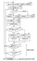
次に、図2に示したMPPT制御機能部31及び図3に示したMPPT制御機能部51の処理について説明する。MPPT制御機能部31,51は同じ処理を行う。図4は、MPPT制御機能部31,51による最大電力点追従制御の処理を示すフローチャートである。MPPT制御機能部31,51は、初期設定手段、制御手段及び回帰判定手段を備えている。初期設定手段は、図4に示すステップS401及びステップS402の処理を行い、制御手段は、ステップS403〜ステップS412の処理を行い、回帰判定手段は、ステップS413及びステップS414の処理を行う。
[Process of MPPT control function unit]
Next, processing of the MPPT
図6は、MPPT制御機能部31,51の機能を説明する図である。このMPPT制御機能部31,51は、電力演算部71、前回電力データ格納部72、演算器73、比較器74、シフト方向判別部75、MPPT制御指令部76及び演算器77により、図4に示す処理を行う。
FIG. 6 is a diagram for explaining the functions of the MPPT
(最大出力電圧(定格電圧)を基準とした初期処理)
まず、MPPT制御機能部31,51は、最大出力電圧(定格電圧)V0を基準とした初期処理を行う(ステップS401)。図10に示したステップS1001では、開放電圧V0を基準とした初期処理を行うが、本発明の実施形態では、最大出力電圧(定格電圧)V0を基準とした初期処理を行う。
(Initial processing based on maximum output voltage (rated voltage))
First, the MPPT
図5は、図4に示したステップS401の処理の詳細を示すフローチャートである。MPPT制御機能部31,51は、MPPT制御の開始の制御電圧Vとして最大出力電圧(定格電圧)すなわち定格出力制御電圧V0を設定する(V=V0、ステップS501)。最大出力電圧(定格電圧)V0は、太陽電池パネル10の仕様として太陽電池パネル10のパネル前面等に記載されており、オペレータの操作により予めMPPT制御機能部31,51に入力されているものとする。ここで、最大出力電圧(定格電圧)V0とは、所定の日射量(図11に示した特性Aの日射量1000W/m2)において、最大出力が得られる電圧であり、太陽電池パネル10には最大出力電圧(または定格電圧)等の名目で表示されることが決められている。
FIG. 5 is a flowchart showing details of the process in step S401 shown in FIG. The MPPT
MPPT制御機能部31,51は、定格出力Pratedを設定する(ステップS502)。定格出力Pratedは、太陽電池パネル10の仕様として太陽電池パネル10のパネル前面等に記載されており、オペレータの操作により予めMPPT制御機能部31,51に入力されているものとする。ここで、定格出力Pratedとは、所定の日射量(図11に示した特性Aの日射量1000W/m2)において、安定して出力可能な電力の定格を示し、太陽電池パネル10に応じて予め決められている。
The MPPT
MPPT制御機能部31,51は、太陽電池パネル10から、制御電圧V0に応じた出力電力(定格電圧時出力電力)P0を取り込む(P=P0、ステップS503)。具体的には、MPPT制御機能部31は、電流検出器32から入力した出力電流と電圧検出器33から入力した出力電圧とを乗算することにより、太陽電池パネル10の出力電力を算出する。MPPT制御機能部51は、電流検出器52から入力した出力電流と電圧検出器53から入力した出力電圧とを乗算することにより、太陽電池パネル10の出力電力を算出する。
The MPPT
MPPT制御機能部31,51は、制御電圧Vのシフト回数n=0を設定する(ステップS504)。このシフト回数はシフトカウンタに設定され、シフトカウンタは、後述するステップS404またはステップS405において制御電圧Vがシフトする毎に更新される。そして、MPPT制御機能部31,51は、制御電圧Vのシフト方向を定めるために、ステップS502にて設定した定格出力Pratedと、ステップS503にて取り込んだ定格電圧時出力電力P0とを比較し、定格電圧時出力電力P0が定格出力Pratedよりも小さいか否かを判定する(ステップS505)。
The MPPT
MPPT制御機能部31,51は、ステップS505において、定格電圧時出力電力P0が定格出力Pratedよりも小さいと判定した場合(ステップS505:Y)、太陽電池パネル10の特性は図12に示した特性Cであると判断し、制御電圧Vのシフト方向を定めるパラメータcとして、反時計回りを示すデータを設定する(c=−1、ステップS506)。定格電圧時出力電力P0が定格出力Pratedよりも小さい場合に反時計回りを示すパラメータc=−1を設定するのは、図12に示した特性Cのように、最大電力の動作点(V4,P4)が定格電圧時出力電力P0の動作点(V0,P0)よりも反時計回り(左側)の位置に存在するため、制御電圧Vをシフト電圧ΔV毎に引き下げるためである。
When the MPPT
一方、MPPT制御機能部31,51は、ステップS505において、定格電圧時出力電力P0が定格出力Pratedよりも小さくない(定格電圧時出力電力P0が定格出力Prated以上である)と判定した場合(ステップS505:N)、太陽電池パネル10の特性は図11に示した特性Aまたは図12に示した特性Bであると判断し、制御電圧Vのシフト方向を定めるパラメータcとして、時計回りを示すデータを設定する(c=1、ステップS507)。定格電圧時出力電力P0が定格出力Prated以上である場合に時計回りを示すパラメータc=1を設定するのは、例えば図12に示した特性Bのように、最大電力の動作点(V-2,P-2)が定格電圧時出力電力P0の動作点(V0,P0)よりも時計回り(右側)の位置に存在するため、制御電圧Vをシフト電圧ΔV毎に引き上げるためである。
On the other hand, the MPPT
MPPT制御機能部31,51は、ステップS506またはステップS507の後、図4に示すステップS402へ移行する。すなわち、図5に示したステップS504〜ステップS507は、定格電圧時出力電力P0と定格出力Pratedとを比較して制御電圧Vのシフト方向を判別する処理である(図4の後述するステップS403〜ステップS405は、得られた今回(N回目)の出力電力PNと前回(N−1回目)の出力電力PN−1とを比較させる同様な機能である)。
The MPPT
(制御電圧Vのシフト)
図4に戻って、MPPT制御機能部31,51は、ステップS401の後(図5のステップS506またはステップS507から移行して)、基準電力PPとして定格電圧時出力電力P0を設定する(PP=P0、ステップS402)。基準電力PPは、後述するステップS408の比較処理において、前回の出力電力Pとして用いられる。
(Shift of control voltage V)
Returning to FIG. 4, the MPPT
図4のステップS403〜ステップS405は、図10に示したステップS1003〜ステップS1005に相当する。また、図4のステップS407〜ステップS412は、図10に示したステップS1006〜ステップS1011に相当する。図4のステップS406は、図10に存在しない処理である。 Steps S403 to S405 in FIG. 4 correspond to steps S1003 to S1005 shown in FIG. Also, step S407 to step S412 in FIG. 4 correspond to step S1006 to step S1011 shown in FIG. Step S406 in FIG. 4 is processing that does not exist in FIG.
MPPT制御機能部31,51は、パラメータcが1(時計回り)であるか−1(反時計回り)であるかを判定し(ステップS403)、c=−1(反時計回り)の場合(ステップS403:c=−1)、制御電圧Vを下げる方向へシフトさせるために、前回の制御電圧Vからシフト電圧ΔVを減算して新たな今回の制御電圧Vを設定する(V(今回)=V(前回)−ΔV、ステップS404)。また、MPPT制御機能部31,51は、c=1(時計回り)の場合(ステップS403:c=1)、制御電圧Vを上げる方向へシフトさせるために、前回の制御電圧Vにシフト電圧ΔVを加算して新たな今回の制御電圧Vを設定する(V(今回)=V(前回)+ΔV、ステップS405)。
The MPPT
図12に示した特性Cの場合、制御電圧Vは、V0からV5まで下がる方向へシフトする。このときのパラメータcは−1である。また、図12に示した特性Bの場合、制御電圧Vは、V0からV-3まで上がる方向へシフトする。このときのパラメータcは1である。 In the case of the characteristic C shown in FIG. 12, the control voltage V shifts in a direction that decreases from V 0 to V 5 . The parameter c at this time is -1. Further, in the case of the characteristic B shown in FIG. 12, the control voltage V shifts in a direction increasing from V 0 to V −3 . The parameter c at this time is 1.
MPPT制御機能部31,51は、ステップS404またはステップS405において制御電圧Vをシフトさせた後、シフト回数nをインクリメントする(n=n+1、ステップS406)。そして、MPPT制御機能部31,51は、太陽電池パネル10から、新たな今回の制御電圧Vに応じた出力電力Pを取り込む(ステップS407)。
The MPPT
図12に示した特性Cの場合、ステップS407の1回目の処理では、制御電圧V1に応じた出力電力P1が取り込まれ、特性A,Bの場合、ステップS407の1回目の処理では、制御電圧V-1に応じた出力電力P-1が取り込まれる。 For characteristic C shown in FIG. 12, in the first process of step S407, the control voltage output power P 1 corresponding to V 1 is taken, if the characteristics A, B, by the first process of step S407 is The output power P −1 corresponding to the control voltage V −1 is taken.
(基準電力PPの更新、パラメータcの設定)
MPPT制御機能部31,51は、出力電力P(今回の出力電力P)と基準電力PP(前回の出力電力P(前回に取り込んだ出力電力P))とを比較し、出力電力Pが基準電力PPよりも大きいか否かを判定し(ステップS408)、出力電力Pが基準電力PPよりも大きい場合(ステップS408:Y)、基準電力PPとして出力電力Pを設定することで基準電力PPを更新し(PP=P、ステップS409)、パラメータcをそのままに維持する(c=+c、ステップS410)。そして、ステップS413へ移行する。
(Update of reference power PP, setting of parameter c)
The MPPT
また、MPPT制御機能部31,51は、出力電力Pが基準電力PPよりも大きくない(出力電力Pが基準電力PP以下である)場合(ステップS408:N)、基準電力PPとして出力電力Pを設定することで基準電力PPを更新し(PP=P、ステップS411)、パラメータcの極性を反転する(c=−c、ステップS412)。そして、ステップS413へ移行する。
Further, when the output power P is not larger than the reference power PP (the output power P is equal to or lower than the reference power PP) (step S408: N), the MPPT
ここで、出力電力Pは、図6に示した電力演算部71により算出される。また、基準電力PP(前回の出力電力P)は、前回電力データ格納部72に格納され、出力電力P(今回の出力電力P)と基準電力PP(前回の出力電力P)との比較は、演算器73及び比較器74により行われる。また、制御電圧Vのシフト方向を示すパラメータcの設定(シフト方向の判別)は、シフト方向判別部75により行われる。この場合、MPPT制御指令部76は、最大出力電圧(定格電圧)V0を演算器77に出力すると共に、シフト方向判別部75により設定されたパラメータcに応じて演算した、MPPT制御の開始点である最大出力電圧(定格電圧)V0を基準にしたプラス側またはマイナス側の電圧値を演算器77に出力する。演算器77は、MPPT制御指令部76から最大出力電圧(定格電圧)V0及びプラス側またはマイナス側の電圧値を入力し、図2または図3に示した電圧検出器33,53から電圧FBを入力する。そして、演算器77は、最大出力電圧(定格電圧)V0に電圧値を加算し、または最大出力電圧(定格電圧)V0から電圧値を減算することで制御電圧Vを求め、制御電圧Vから電圧FBを減算して電圧偏差を算出し、電圧偏差を、図2に示した演算器38または図3に示した電圧制御器55に出力する。
Here, the output power P is calculated by the
(特性Cの動作)
図12に示した特性Cの場合、出力電力P0,・・・,P4は、制御電圧V0からV4まで変化するに従って増加する。これにより、制御電圧V0〜V4及び出力電力P0〜P4の領域では、ステップS408にて出力電力Pは基準電力PPよりも大きいと判定され、ステップS409にて基準電力PPは更新され、ステップS410にてパラメータcは−1に維持される。これにより、制御電圧Vは、V0からV4までの間でシフト電圧ΔV毎に継続して下げられ、これに伴って出力電力Pは、P0からP4まで増加する。そして、出力電力P4,P5は、制御電圧V4からV5まで変化するに従って減少する。これにより、制御電圧V4,V5及び出力電力P4,P5の領域では、ステップS408にて出力電力P5は基準電力PP=P4よりも大きくないと判定され、ステップS411にて基準電力PPがP5に更新され、ステップS412にてパラメータcの極性は反転され、c=1に設定される。これにより、制御電圧Vは、ステップS405において、V5からV4に上げられ、これに伴って出力電力Pは、P5からP4に増加する。
(Operation of characteristic C)
In the case of the characteristic C shown in FIG. 12, the output powers P 0 ,..., P 4 increase as they change from the control voltage V 0 to V 4 . As a result, in the region of the control voltages V 0 to V 4 and the output power P 0 to P 4 , it is determined in step S408 that the output power P is larger than the reference power PP, and the reference power PP is updated in step S409. In step S410, the parameter c is maintained at -1. As a result, the control voltage V is continuously decreased for each shift voltage ΔV between V 0 and V 4 , and the output power P increases from P 0 to P 4 accordingly. The output powers P 4 and P 5 decrease as they change from the control voltage V 4 to V 5 . Thereby, in the region of the control voltages V 4 and V 5 and the output powers P 4 and P 5 , it is determined in step S408 that the output power P 5 is not larger than the reference power PP = P 4 , and in step S411, the reference power is determined. power PP is updated to P 5, the polarity of the parameter c is inverted in step S412, it is set to c = 1. As a result, the control voltage V is increased from V 5 to V 4 in step S405, and the output power P is increased from P 5 to P 4 accordingly.
そして、ステップS408にて出力電力P4は基準電力PP=P5よりも大きいと判定され、ステップS409にて基準電力PPはP4に更新され、ステップS410にてパラメータcは1に維持される。これにより、制御電圧Vは、ステップS405において、V4からV3に上げられ、これに伴って出力電力Pは、P4からP3に減少する。 In step S408, it is determined that the output power P 4 is greater than the reference power PP = P 5, the reference power PP is updated to P 4 in step S409, and the parameter c is maintained at 1 in step S410. . As a result, the control voltage V is increased from V 4 to V 3 in step S405, and the output power P is decreased from P 4 to P 3 accordingly.
そして、ステップS408にて出力電力P3は基準電力PP=P4よりも大きくないと判定され、ステップS411にて基準電力PPはP3に更新され、ステップS412にてパラメータcの極性は反転し、c=−1に設定される。これにより、制御電圧Vは、ステップS404において、V3からV4に下げられ、これに伴って出力電力Pは、P3からP4に増加する。 In step S408, it is determined that the output power P 3 is not larger than the reference power PP = P 4, the reference power PP is updated to P 3 in step S411, and the polarity of the parameter c is inverted in step S412. , C = −1. Thereby, the control voltage V is lowered from V 3 to V 4 in step S404, and the output power P is increased from P 3 to P 4 accordingly.
このように、出力電力Pが最大の出力電力P4に到達するまでの間、動作点は(V0,P0)から(V4,P4)まで移行し、その後、最大の出力電力P4である動作点(V4,P4)を中心に、動作点(V5,P5)と動作点(V3,P3)との間の移行を繰り返す。 Thus, the operating point shifts from (V 0 , P 0 ) to (V 4 , P 4 ) until the output power P reaches the maximum output power P 4 , and then the maximum output power P 4 is a operating point (V 4, P 4) in the center, and repeats the transition between the operating point (V 5, P 5) and the operating point (V 3, P 3).
これにより、最大の出力電力の動作点(V4,P4)を中心にして制御電圧Vは維持され、最高の効率で太陽電池パネル10の発電を維持することができる。また、最大の出力電力の動作点(V4,P4)まで短時間に到達することができるから無駄な電力消費をなくし、MPPT制御を効率的に行うことが可能となる。
Thereby, the control voltage V is maintained around the operating point (V 4 , P 4 ) of the maximum output power, and the power generation of the
(特性Bの動作)
図12に示した特性Bの場合、出力電力P0,P-1,P-2は、制御電圧V0からV-2まで変化するに従って増加する。これにより、制御電圧V0〜V-2及び出力電力P0〜P-2の領域では、ステップS408にて出力電力Pは基準電力PPよりも大きいと判定され、ステップS409にて基準電力PPは更新され、ステップS410にてパラメータcは1に維持される。これにより、制御電圧Vは、V0からV-2までの間でシフト電圧ΔV毎に継続して上げられ、これに伴って出力電力Pは、P0からP-2まで増加する。そして、出力電力P-2,P-3は、制御電圧V-2からV-3まで変化するに従って減少する。これにより、制御電圧V-2,V-3及び出力電力P-2,P-3の領域では、ステップS408にて出力電力P-3は基準電力PP=P-2よりも大きくないと判定され、ステップS411にて基準電力PPがP-3に更新され、ステップS412にてパラメータcの極性は反転され、c=−1に設定される。これにより、制御電圧Vは、ステップS404において、V-3からV-2に下げられ、これに伴って出力電力Pは、P-3からP-2に増加する。
(Operation of characteristic B)
In the case of the characteristic B shown in FIG. 12, the output powers P 0 , P −1 and P −2 increase as they change from the control voltage V 0 to V −2 . Thereby, in the region of the control voltages V 0 to V −2 and the output power P 0 to P −2 , it is determined in step S408 that the output power P is larger than the reference power PP, and in step S409, the reference power PP is The parameter c is maintained at 1 in step S410. As a result, the control voltage V is continuously increased for each shift voltage ΔV between V 0 and V −2 , and the output power P increases from P 0 to P −2 accordingly. The output powers P -2 and P -3 decrease as they change from the control voltage V -2 to V -3 . As a result, in the regions of the control voltages V -2 and V -3 and the output powers P -2 and P -3 , it is determined in step S408 that the output power P -3 is not larger than the reference power PP = P -2. In step S411, the reference power PP is updated to P- 3 . In step S412, the polarity of the parameter c is inverted, and c = -1. As a result, the control voltage V is lowered from V −3 to V −2 in step S404, and the output power P increases from P −3 to P −2 accordingly.
そして、ステップS408にて出力電力P-2は基準電力PP=P-3よりも大きいと判定され、ステップS409にて基準電力PPはP-2に更新され、ステップS410にてパラメータcは−1に維持される。これにより、制御電圧Vは、ステップS404において、V-2からV-1に下げられ、これに伴って出力電力Pは、P-2からP-1に減少する。 In step S408, the output power P- 2 is determined to be larger than the reference power PP = P- 3, the reference power PP is updated to P- 2 in step S409, and the parameter c is set to -1 in step S410. Maintained. As a result, the control voltage V is lowered from V −2 to V −1 in step S404, and the output power P is reduced from P −2 to P −1 accordingly.
そして、ステップS408にて出力電力P-1は基準電力PP=P-2よりも大きくないと判定され、ステップS411にて基準電力PPはP-1に更新され、ステップS412にてパラメータcの極性は反転し、c=1に設定される。これにより、制御電圧Vは、ステップS404において、V-1からV-2に上げられ、これに伴って出力電力Pは、P-1からP-2に増加する。 Then, it is determined in step S408 that the output power P −1 is not larger than the reference power PP = P −2, the reference power PP is updated to P −1 in step S411, and the polarity of the parameter c is determined in step S412. Is inverted and c = 1 is set. As a result, the control voltage V is increased from V −1 to V −2 in step S404, and the output power P is increased from P −1 to P −2 accordingly.
このように、出力電力Pが最大の出力電力P-2に到達するまでの間、動作点は(V0,P0)から(V-2,P-2)まで移行し、その後、最大の出力電力P-2である動作点(V-2,P-2)を中心に、動作点(V-3,P-3)と動作点(V-1,P-1)との間の移行を繰り返す。 Thus, the operating point shifts from (V 0 , P 0 ) to (V −2 , P −2 ) until the output power P reaches the maximum output power P −2, and then reaches the maximum. The transition between the operating point (V -3 , P -3 ) and the operating point (V -1 , P -1 ) with the operating point (V -2 , P -2 ) being the output power P -2 as the center. repeat.
これにより、最大の出力電力の動作点(V-2,P-2)を中心にして制御電圧Vは維持され、最高の効率で太陽電池パネル10の発電を維持することができる。また、最大の出力電力の動作点(V-2,P-2)まで短時間に到達することができ、MPPT制御を効率的に行うことが可能となり、発電効率を高めることができる。
As a result, the control voltage V is maintained around the operating point (V -2 , P -2 ) of the maximum output power, and the power generation of the
(回帰判定処理/制御不能判定処理)
図4に戻って、MPPT制御機能部31,51は、ステップS410またはステップS412から移行して、回帰判定処理を行う。回帰判定処理は、MPPT制御が不能な状況であるか否かを判定する制御不能判定処理である。これにより、MPPT制御が不能であり回帰する場合、ステップS401にて最大出力電圧(定格電圧)V0を基準とした初期処理が行われ、MPPT制御を再スタートさせることができる。
(Regression judgment process / uncontrollable judgment process)
Returning to FIG. 4, the MPPT
具体的には、MPPT制御機能部31,51は、図5に示したステップS502にて取り込んだ定格時出力電力P0と、図4に示したステップS407にて取り込んだ出力電力P(今回の出力電力P)とを比較し、定格電圧時出力電力P0が出力電力Pよりも小さいか否かを判定する(ステップS413)。
Specifically, the MPPT
MPPT制御機能部31,51は、ステップS413において、定格電圧時出力電力P0が出力電力Pよりも小さいと判定した場合(ステップS413:Y)、ステップS406にて設定した、制御電圧Vのシフト回数nと、予め設定されたシフト回数制限値Nとを比較し、シフト回数nがシフト回数制限値Nよりも小さいか否かを判定する(ステップS414)。
When the MPPT
MPPT制御機能部31,51は、ステップS414において、シフト回数nがシフト回数制限値Nよりも小さいと判定した場合(ステップS414:Y)、MPPT制御が不能でなく回帰無しを判断し、ステップS403へ移行する。
If the MPPT
これにより、定格電圧時出力電力P0が出力電力Pよりも小さく、かつシフト回数nがシフト回数制限値Nよりも小さい場合、MPPT制御は正しく行われていると判断され、ステップS401における最大出力電圧(定格電圧)V0を基準とした初期処理へ移行する回帰処理は行われない。つまり、制御電圧Vをシフトする処理が継続し、最大出力の動作点が導出される。 Thus, when the rated voltage output power P 0 is smaller than the output power P and the number of shifts n is smaller than the shift number limit value N, it is determined that the MPPT control is correctly performed, and the maximum output in step S401 is determined. The regression process that shifts to the initial process based on the voltage (rated voltage) V 0 is not performed. That is, the process of shifting the control voltage V continues, and the maximum output operating point is derived.
一方、MPPT制御機能部31,51は、ステップS413において、定格電圧時出力電力P0が出力電力Pよりも小さくない(定格電圧時出力電力P0が出力電力P以上である)と判定した場合(ステップS413:N)、または、ステップS414において、シフト回数nがシフト回数制限値Nよりも小さくない(シフト回数nがシフト回数制限値N以上である)と判定した場合(ステップS414:N)、MPPT制御が不能であり回帰有りを判断し、ステップS401へ移行する。
On the other hand, when the MPPT
これにより、定格電圧時出力電力P0が出力電力P以上である場合、またはシフト回数nがシフト回数制限値N以上である場合、MPPT制御は正しく行われていないと判断され、ステップS401における最大出力電圧(定格電圧)V0を基準とした初期処理へ移行する回帰処理が行われ、MPPT制御を再スタートさせることができる。この場合、図5に示したステップS504においてシフト回数nがリセットされ、制御電圧Vをシフトする処理が再び継続し、最大出力の動作点が導出される。 Thereby, when the output power P 0 at the rated voltage is equal to or higher than the output power P, or when the shift number n is equal to or larger than the shift number limit value N, it is determined that the MPPT control is not performed correctly, and the maximum in step S401 A regression process for shifting to the initial process based on the output voltage (rated voltage) V 0 is performed, and the MPPT control can be restarted. In this case, the number of shifts n is reset in step S504 shown in FIG. 5, the process of shifting the control voltage V is continued again, and the maximum output operating point is derived.
日射量は気象条件により異なり、また日陰の影響等によっても異なる。このため、日射量が変化すると太陽電池パネル10の発電電力は不安定となり、結果としてMPPT制御が不能となる可能性がある。そこで、図4のステップS413及びステップS414に示したように、MPPT制御機能部31,51は、定格電圧時出力電力P0と出力電力Pとを比較すると共に、制御電圧Vのシフト回数nとシフト回数制限値Nとを比較し、定格電圧時出力電力P0が出力電力P以上である場合、またはシフト回数nがシフト回数制限値N以上である場合、MPPT制御が不能であると判断するようにした。例えば、日射量が減少したときは出力電力Pが下がるから、定格電圧時出力電力P0が出力電力P以上であると判定されることがあり得る。また、日射量が上下に変化したときは最大出力の動作点の導出に時間がかかるから、シフト回数nがシフト回数制限値N以上であると判定されることがあり得る。
The amount of solar radiation varies depending on weather conditions and also depends on the influence of the shade. For this reason, when the amount of solar radiation changes, the generated electric power of the
これにより、MPPT制御が不能であると判断された場合、図4に示したステップS401における最大出力電圧(定格電圧)V0を基準とした初期処理へ移行する回帰処理が行われ、MPPT制御を再スタートさせることができる。したがって、制御電圧Vの不要なシフト処理を回避し、MPPT制御が不能な状況から脱出することができ、最大出力の動作点が導出される。 Accordingly, when it is determined that the MPPT control is impossible, a regression process is performed to shift to the initial process based on the maximum output voltage (rated voltage) V 0 in step S401 shown in FIG. It can be restarted. Therefore, unnecessary shift processing of the control voltage V can be avoided, and the situation where MPPT control is impossible can be escaped, and the operating point of the maximum output is derived.
以上のように、本発明の実施形態による太陽光発電装置によれば、パワーコンディショナ12のMPPT制御機能部31及びDC−DCコンバータ13のMPPT制御機能部51は、最大出力電圧(定格電圧)V0を基準とした初期処理において、MPPT制御の開始の制御電圧Vとして最大出力電圧(定格電圧)V0を設定するようにした。これにより、最大出力電圧(定格電圧)V0からMPPT制御を開始するから、最大の出力電力の動作点まで短時間に到達することができ、無駄な電力消費をなくし、MPPT制御を効率的に行うことが可能となる。
As described above, according to the photovoltaic power generation apparatus according to the embodiment of the present invention, the MPPT
また、MPPT制御機能部31,51は、定格電圧時出力電力P0が出力電力P以上であると判定した場合、または制御電圧Vのシフト回数nがシフト回数制限値N以上であると判定した場合、MPPT制御が不能であると判断し、最大出力電圧(定格電圧)V0を基準とした初期処理から再スタートするようにした。これにより、天候または日陰等により日射量が変化し、MPPT制御が不能になった場合に、MPPT制御を初期に戻すことができるから、制御不能状態を回避すると共に、制御不能時の無駄な電力消費をなくし、MPPT制御を効率的に行うことが可能となる。
Further, the MPPT
尚、本発明の実施形態による太陽光発電装置におけるパワーコンディショナ12のMPPT制御機能部31及びDC−DCコンバータ13のMPPT制御機能部51のハードウェア構成としては、マイクロプロセッサMPU等により実現することができる。MPPT制御機能部31,51は、MPU、CPU、RAM等の揮発性の記憶媒体、ROM等の不揮発性の記憶媒体、及びインターフェース等を備えたコンピュータによって構成される。MPPT制御機能部31,51に備えた初期設定手段、制御手段及び回帰判定手段の各機能は、これらの機能を記述したプログラムをCPUに実行させることによりそれぞれ実現される。また、これらのプログラムは、磁気ディスク(フロッピー(登録商標)ディスク、ハードディスク等)、光ディスク(CD−ROM、DVD等)、半導体メモリ等の記憶媒体に格納して頒布することもでき、ネットワークを介して送受信することもできる。
Note that the hardware configurations of the MPPT
以上、実施形態を挙げて本発明を説明したが、本発明は前記実施形態に限定されるものではなく、その技術思想を逸脱しない範囲で種々変形可能である。前記実施形態では、太陽電池パネル10の制御電圧Vに対するシフト電圧ΔVを固定にして、今回の制御電圧Vにおける出力電力Pと、前回の制御電圧Vにおける出力電力Pである基準電力PPとを比較し、その増減に応じてシフト方向を変えながら制御電圧Vのシフトを繰り返す制御を行う手法を例にして説明したが、本発明は、前述の特許文献1等のように、制御電圧Vのシフト電圧ΔVを固定にしないで、出力電圧Vまたは出力電力Pの差分に比例したシフト電圧ΔVを決定して制御を行う手法にも適用がある。
The present invention has been described with reference to the embodiment. However, the present invention is not limited to the above-described embodiment, and various modifications can be made without departing from the technical idea thereof. In the embodiment, the shift voltage ΔV with respect to the control voltage V of the
また、前記実施形態では、MPPT制御機能部31,51は、定格電圧時出力電力P0と出力電力Pとを比較すると共に、制御電圧Vのシフト回数nとシフト回数制限値Nとを比較し、これらの比較結果からMPPT制御が不能であると判断するようにした。これに対し、MPPT制御機能部31,51は、定格電圧時出力電力P0と出力電力Pとの比較処理のみを行い、この比較結果に従ってMPPT制御が不能であると判断するようにしてもよいし、制御電圧Vのシフト回数nとシフト回数制限値Nとの比較処理のみを行い、この比較結果に従ってMPPT制御が不能であると判断するようにしてもよい。
In the embodiment, the MPPT
また、前記実施形態では、図4に示したステップS414において、MPPT制御機能部31,51が制御電圧Vのシフト回数nとシフト回数制限値Nとを比較する際のシフト回数制限値Nとして、予め設定された値を用いたが、定格電圧時出力電力P0に応じた値を用いるようにしてもよい。具体的には、MPPT制御機能部31,51は、定格電圧時出力電力P0が大きい場合はシフト回数制限値Nが小さくなり、定格電圧時出力電力P0が小さい場合はシフト回数制限値Nが大きくなるように、定格電圧時出力電力P0の大きさに応じてシフト回数制限値Nを相対的に設定する。これにより、定格電圧時出力電力P0が大きい場合、最大電力の動作点が導出されるまで時間がさほどかからないから、シフト回数制限値Nとして小さい値が設定され、定格電圧時出力電力P0が小さい場合、最大電力の動作点が導出されるまで時間はある程度かかるから、シフト回数制限値Nとして大きい値が設定される。したがって、安定したMPPT制御を実現することができる。
In the above embodiment, the MPPT
1,2 太陽光発電システム
10 太陽電池パネル
11 接続箱
12,14 パワーコンディショナ
13 DC−DCコンバータ
21 電流源
22 ダイオード
23,24 抵抗
31,51 MPPT制御機能部
32,35,52,56 電流検出器
33,53 電圧検出器
38,57,73,77 演算器
36 電気角検出器
37 電流FB3相/2相演算器
39 電流指令2相/3相演算器
40,59 PWM制御器
41,60 パワー変換器
55 電圧制御器
58 電流制御器
71 電力演算部
72 前回電力データ格納部
74 比較器
75 シフト方向判別部
76 MPPT制御指令部
DESCRIPTION OF
Claims (7)
前記制御部は、
前記追従制御の開始時に、前記制御電圧として前記太陽電池パネルの所定の定格電圧を設定し、前記制御電圧に応じた出力電力を定格電圧時出力電力として取り込み、前記定格電圧時出力電力が前記太陽電池パネルの所定の定格出力よりも小さいと判定した場合、前記制御電圧のシフト方向を下げる方向に設定し、前記定格電圧時出力電力が前記所定の定格出力よりも小さくないと判定した場合、前記制御電圧のシフト方向を上げる方向に設定する初期設定手段と、
前記制御電圧をシフトさせて新たな制御電圧を設定し、前記新たな制御電圧に応じた出力電力を取り込み、前記取り込んだ今回の出力電力と前回の出力電力とを比較し、今回の出力電力が前回の出力電力よりも大きいと判定した場合、前記シフト方向を維持し、今回の出力電力が前回の出力電力よりも大きくないと判定した場合、前記シフトさせた方向とは反対のシフト方向を設定する制御手段と、を備え、
前記制御手段は、前記初期設定手段により設定されたシフト方向の新たな制御電圧を設定し、当該制御手段が設定したシフト方向の新たな制御電圧を順次設定し、前記出力電力が最大となる動作点を追従制御する、ことを特徴とする太陽光発電装置。 In a photovoltaic power generation apparatus including a control unit that shifts the control voltage of the solar cell panel and controls to control the operating point at which the output power of the solar cell panel becomes maximum,
The controller is
At the start of the follow-up control, a predetermined rated voltage of the solar cell panel is set as the control voltage, and output power corresponding to the control voltage is taken in as output power at rated voltage, and the output power at rated voltage is the solar power When it is determined that the battery panel is smaller than the predetermined rated output, the shift direction of the control voltage is set to be reduced, and when the rated voltage output power is determined not to be smaller than the predetermined rated output, Initial setting means for setting the control voltage shift direction to be increased ;
The control voltage is shifted to set a new control voltage, the output power corresponding to the new control voltage is captured, the captured current output power is compared with the previous output power, and the current output power is If it is determined that the output power is greater than the previous output power, the shift direction is maintained, and if it is determined that the current output power is not greater than the previous output power, a shift direction opposite to the shifted direction is set. Control means for
The control means sets a new control voltage in the shift direction set by the initial setting means, sequentially sets a new control voltage in the shift direction set by the control means, and operates to maximize the output power. A photovoltaic power generation apparatus characterized by following and controlling a point .
前記制御部は、
前記追従制御の開始時に、前記制御電圧として前記太陽電池パネルの所定の定格電圧を設定し、前記制御電圧に応じた出力電力を定格電圧時出力電力として取り込み、前記定格電圧時出力電力と前記太陽電池パネルの所定の定格出力との比較結果に基づいて、前記制御電圧のシフト方向を設定する初期設定手段と、
前記制御電圧をシフトさせて新たな制御電圧を設定し、前記新たな制御電圧に応じた出力電力を取り込み、前記取り込んだ今回の出力電力と前回の出力電力とを比較し、今回の出力電力が前回の出力電力よりも大きいと判定した場合、前記シフト方向を維持し、今回の出力電力が前回の出力電力よりも大きくないと判定した場合、前記シフトさせた方向とは反対のシフト方向を設定する制御手段と、を備え、
前記制御手段は、前記初期設定手段により設定されたシフト方向の新たな制御電圧を設定し、当該制御手段が設定したシフト方向の新たな制御電圧を順次設定し、前記出力電力が最大となる動作点を追従制御し、
前記制御部は、さらに、回帰判定手段を備え、
前記回帰判定手段は、
前記定格電圧時出力電力と前記制御手段により取り込まれた今回の出力電力とを比較し、前記定格電圧時出力電力が今回の出力電力よりも小さいと判定した場合、回帰無しを判断し、前記定格電圧時出力電力が今回の出力電力よりも小さくないと判定した場合、回帰有りを判断し、
前記回帰無しが判断された場合、前記制御手段が、前記新たな制御電圧の設定、前記出力電力の取り込み及び前記シフト方向の設定を行い、
前記回帰有りが判断された場合、前記初期設定手段が、前記追従制御の開始時と同じ処理を再度行い、前記制御手段が、前記新たな制御電圧の設定、前記出力電力の取り込み及び前記シフト方向の設定を行う、ことを特徴とする太陽光発電装置。 In a photovoltaic power generation apparatus including a control unit that shifts the control voltage of the solar cell panel and controls to control the operating point at which the output power of the solar cell panel becomes maximum,
The controller is
At the start of the follow-up control, a predetermined rated voltage of the solar cell panel is set as the control voltage, and output power corresponding to the control voltage is taken in as output power at rated voltage. Initial setting means for setting a shift direction of the control voltage based on a comparison result with a predetermined rated output of the battery panel;
The control voltage is shifted to set a new control voltage, the output power corresponding to the new control voltage is captured, the captured current output power is compared with the previous output power, and the current output power is If it is determined that the output power is greater than the previous output power, the shift direction is maintained, and if it is determined that the current output power is not greater than the previous output power, a shift direction opposite to the shifted direction is set. Control means for
The control means sets a new control voltage in the shift direction set by the initial setting means, sequentially sets a new control voltage in the shift direction set by the control means, and operates to maximize the output power. Follow the point,
The control unit further includes regression determination means,
The regression determination means includes
Comparing the output power at the rated voltage with the current output power taken in by the control means, and determining that the output power at the rated voltage is smaller than the current output power, determining no regression, the rating When it is determined that the output power at voltage is not smaller than the current output power, it is determined that there is a regression,
When it is determined that there is no regression, the control means performs setting of the new control voltage, capturing of the output power and setting of the shift direction,
When it is determined that the regression is present, the initial setting unit performs the same process as that at the start of the follow-up control again, and the control unit sets the new control voltage, takes in the output power, and the shift direction. The photovoltaic power generation apparatus characterized by performing the setting.
前記制御部は、
前記追従制御の開始時に、前記制御電圧として前記太陽電池パネルの所定の定格電圧を設定し、前記制御電圧に応じた出力電力を定格電圧時出力電力として取り込み、前記定格電圧時出力電力と前記太陽電池パネルの所定の定格出力との比較結果に基づいて、前記制御電圧のシフト方向を設定する初期設定手段と、
前記制御電圧をシフトさせて新たな制御電圧を設定し、前記新たな制御電圧に応じた出力電力を取り込み、前記取り込んだ今回の出力電力と前回の出力電力とを比較し、今回の出力電力が前回の出力電力よりも大きいと判定した場合、前記シフト方向を維持し、今回の出力電力が前回の出力電力よりも大きくないと判定した場合、前記シフトさせた方向とは反対のシフト方向を設定する制御手段と、を備え、
前記制御手段は、前記初期設定手段により設定されたシフト方向の新たな制御電圧を設定し、当該制御手段が設定したシフト方向の新たな制御電圧を順次設定し、前記出力電力が最大となる動作点を追従制御し、
前記制御部は、さらに、回帰判定手段を備え、
前記回帰判定手段は、
前記制御手段により新たな制御電圧が設定されたときのシフト回数と所定の制限値とを比較し、前記シフト回数が所定の制限値よりも小さいと判定した場合、回帰無しを判断し、前記シフト回数が所定の制限値よりも小さくないと判定した場合、回帰有りを判断し、
前記回帰無しが判断された場合、前記制御手段が、前記新たな制御電圧の設定、前記出力電圧の取り込み及び前記シフト方向の設定を行い、
前記回帰有りが判断された場合、前記初期設定手段が、前記追従制御の開始時と同じ処理を再度行い、前記制御手段が、前記新たな制御電圧の設定、前記出力電圧の取り込み及び前記シフト方向の設定を行う、ことを特徴とする太陽光発電装置。 In a photovoltaic power generation apparatus including a control unit that shifts the control voltage of the solar cell panel and controls to control the operating point at which the output power of the solar cell panel becomes maximum,
The controller is
At the start of the follow-up control, a predetermined rated voltage of the solar cell panel is set as the control voltage, and output power corresponding to the control voltage is taken in as output power at rated voltage. Initial setting means for setting a shift direction of the control voltage based on a comparison result with a predetermined rated output of the battery panel;
The control voltage is shifted to set a new control voltage, the output power corresponding to the new control voltage is captured, the captured current output power is compared with the previous output power, and the current output power is If it is determined that the output power is greater than the previous output power, the shift direction is maintained, and if it is determined that the current output power is not greater than the previous output power, a shift direction opposite to the shifted direction is set. Control means for
The control means sets a new control voltage in the shift direction set by the initial setting means, sequentially sets a new control voltage in the shift direction set by the control means, and operates to maximize the output power. Follow the point,
The control unit further includes regression determination means,
The regression determination means includes
The number of shifts when a new control voltage is set by the control means is compared with a predetermined limit value, and when it is determined that the number of shifts is smaller than the predetermined limit value, it is determined that there is no regression, and the shift When it is determined that the number of times is not smaller than the predetermined limit value, it is determined that there is a regression,
When it is determined that there is no regression, the control means performs setting of the new control voltage, capturing of the output voltage and setting of the shift direction,
When it is determined that the regression is present, the initial setting means performs the same process as that at the start of the follow-up control again, and the control means sets the new control voltage, takes in the output voltage, and the shift direction. The photovoltaic power generation apparatus characterized by performing the setting.
前記太陽電池パネルの出力電力を3相の電力に変換するパワーコンディショナを備え、
当該パワーコンディショナが前記制御部を備えることを特徴とする太陽光発電装置。 In the solar power generation device according to any one of claims 1 to 3 ,
A power conditioner for converting the output power of the solar cell panel into three-phase power;
The said power conditioner is provided with the said control part, The solar power generation device characterized by the above-mentioned.
前記太陽電池パネルにより出力された電圧を所定の電圧に変換するDC−DCコンバータと、
前記DC−DCコンバータからの出力電力を3相の電力に変換するパワーコンディショナと、を備え、
当該DC−DCコンバータが前記制御部を備えることを特徴とする太陽光発電装置。 In the solar power generation device according to any one of claims 1 to 3 ,
A DC-DC converter that converts the voltage output by the solar cell panel into a predetermined voltage;
And a power conditioner that converts the output power from the DC-DC converter to a three-phase power,
The said DC-DC converter is provided with the said control part, The solar power generation device characterized by the above-mentioned.
前記制御電圧をシフトさせるシフト量を、固定値、前記太陽電池パネルの出力電力に応じた値、または前記太陽電池パネルの出力電圧に応じた値とする、ことを特徴とする太陽光発電装置。 In the solar power generation device according to any one of claims 1 to 5 ,
The amount of shift for shifting the control voltage is a fixed value, a value according to the output power of the solar cell panel, or a value according to the output voltage of the solar cell panel.
前記追従制御の開始時に、前記制御電圧として前記太陽電池パネルの所定の定格電圧を設定し、前記制御電圧に応じた出力電力を定格電圧時出力電力として取り込み、前記定格電圧時出力電力と前記太陽電池パネルの所定の定格出力との比較結果に基づいて、前記制御電圧のシフト方向を設定する第1のステップと、
前記第1のステップにて設定したシフト方向に前記制御電圧をシフトさせて新たな制御電圧を設定する第2のステップと、
前記新たな制御電圧に応じた出力電力を取り込み、前記取り込んだ今回の出力電力と前回の出力電力とを比較し、今回の出力電力が前回の出力電力よりも大きいと判定した場合、前記シフト方向を維持し、今回の出力電力が前回の出力電力よりも大きくないと判定した場合、前記シフトさせた方向とは反対のシフト方向を設定する第3のステップと、
前記第3のステップにて設定したシフト方向に前記制御電圧をシフトさせて新たな制御電圧を設定する第4のステップと、
前記第3のステップと前記第4のステップとを繰り返す第5のステップと、を有し、
前記第5のステップは、さらに、
前記定格電圧時出力電力と前記今回の出力電力とを比較すると共に、前記第4のステップにて新たな制御電圧を設定したときのシフト回数と所定の制限値とを比較し、前記定格電圧時出力電力が今回の出力電力よりも小さくないと判定した場合、または、前記シフト回数が所定の制限値よりも小さくないと判定した場合、前記第1のステップにおける追従制御の開始時と同じ処理を再度行う、ことを特徴とする太陽光発電制御方法。 In a photovoltaic power generation control method that shifts the control voltage of the solar cell panel and follows the operating point at which the output power of the solar cell panel becomes maximum,
At the start of the follow-up control, a predetermined rated voltage of the solar cell panel is set as the control voltage, and output power corresponding to the control voltage is taken in as output power at rated voltage. A first step of setting a shift direction of the control voltage based on a comparison result with a predetermined rated output of the battery panel;
A second step of setting a new control voltage by shifting the control voltage in the shift direction set in the first step;
When the output power corresponding to the new control voltage is captured, the captured current output power is compared with the previous output power, and when it is determined that the current output power is greater than the previous output power, the shift direction And determining that the current output power is not greater than the previous output power, a third step of setting a shift direction opposite to the shifted direction;
A fourth step of setting a new control voltage by shifting the control voltage in the shift direction set in the third step;
A fifth step of repeating the third step and the fourth step,
The fifth step further includes:
The rated voltage output power and the current output power are compared, the number of shifts when a new control voltage is set in the fourth step is compared with a predetermined limit value, and the rated voltage output power is compared. When it is determined that the output power is not smaller than the current output power, or when it is determined that the number of shifts is not smaller than a predetermined limit value, the same processing as that at the start of the follow-up control in the first step is performed. A photovoltaic power generation control method characterized by performing again.
Priority Applications (1)
| Application Number | Priority Date | Filing Date | Title |
|---|---|---|---|
| JP2013225963A JP6284342B2 (en) | 2013-10-30 | 2013-10-30 | Photovoltaic power generation apparatus and photovoltaic power generation control method |
Applications Claiming Priority (1)
| Application Number | Priority Date | Filing Date | Title |
|---|---|---|---|
| JP2013225963A JP6284342B2 (en) | 2013-10-30 | 2013-10-30 | Photovoltaic power generation apparatus and photovoltaic power generation control method |
Publications (2)
| Publication Number | Publication Date |
|---|---|
| JP2015087959A JP2015087959A (en) | 2015-05-07 |
| JP6284342B2 true JP6284342B2 (en) | 2018-02-28 |
Family
ID=53050686
Family Applications (1)
| Application Number | Title | Priority Date | Filing Date |
|---|---|---|---|
| JP2013225963A Active JP6284342B2 (en) | 2013-10-30 | 2013-10-30 | Photovoltaic power generation apparatus and photovoltaic power generation control method |
Country Status (1)
| Country | Link |
|---|---|
| JP (1) | JP6284342B2 (en) |
Cited By (1)
| Publication number | Priority date | Publication date | Assignee | Title |
|---|---|---|---|---|
| US12040624B2 (en) | 2022-03-18 | 2024-07-16 | Kabushiki Kaisha Toshiba | Power conditioning system and power grid operational system |
Families Citing this family (5)
| Publication number | Priority date | Publication date | Assignee | Title |
|---|---|---|---|---|
| CN104950981B (en) * | 2015-05-12 | 2017-03-01 | 江苏固德威电源科技股份有限公司 | The multichannel MPPT method for tracing of Current Sensorless |
| CN105245104A (en) * | 2015-10-30 | 2016-01-13 | 江阴万事兴技术有限公司 | Intelligent photovoltaic power adjustor and adjusting method |
| CN105259972B (en) * | 2015-12-02 | 2016-09-14 | 河海大学 | A kind of multi-peak maximum power point of photovoltaic array tracking based on hopping strategy |
| CN106055020B (en) * | 2016-07-25 | 2017-12-01 | 华南理工大学 | Based on environmental suitability self study maximum photovoltaic power point tracks of device and method |
| JP6786345B2 (en) * | 2016-10-19 | 2020-11-18 | 株式会社Rej | Solar power generator |
Family Cites Families (5)
| Publication number | Priority date | Publication date | Assignee | Title |
|---|---|---|---|---|
| JPH07234733A (en) * | 1994-02-22 | 1995-09-05 | Sanyo Electric Co Ltd | Maximum power point tracking method |
| JP2731117B2 (en) * | 1994-07-29 | 1998-03-25 | 三洋電機株式会社 | Maximum power point tracking control method and apparatus for solar cell |
| JP3352334B2 (en) * | 1996-08-30 | 2002-12-03 | キヤノン株式会社 | Solar cell power controller |
| JP2008015899A (en) * | 2006-07-07 | 2008-01-24 | Ebara Densan Ltd | System interconnection power conditioner |
| JP5748213B2 (en) * | 2011-06-22 | 2015-07-15 | コア・テック株式会社 | Solar power system |
-
2013
- 2013-10-30 JP JP2013225963A patent/JP6284342B2/en active Active
Cited By (1)
| Publication number | Priority date | Publication date | Assignee | Title |
|---|---|---|---|---|
| US12040624B2 (en) | 2022-03-18 | 2024-07-16 | Kabushiki Kaisha Toshiba | Power conditioning system and power grid operational system |
Also Published As
| Publication number | Publication date |
|---|---|
| JP2015087959A (en) | 2015-05-07 |
Similar Documents
| Publication | Publication Date | Title |
|---|---|---|
| JP6284342B2 (en) | Photovoltaic power generation apparatus and photovoltaic power generation control method | |
| JP7248593B2 (en) | Surplus power extraction method and system | |
| JP5320144B2 (en) | Solar cell maximum output power tracking control device | |
| US9450513B2 (en) | Control circuit and control method for inverter circuit, and control circuit and control method for power conversion circuit | |
| JP2005235082A (en) | Method for tracking and controlling maximum power, and power converting device | |
| JP6762680B2 (en) | Solar power system | |
| WO2011115952A1 (en) | Systems and methods for operating a solar direct pump | |
| EP2527948A2 (en) | Maximum power point tracking method | |
| KR102087063B1 (en) | Method and apparatus for improved burst mode during power conversion | |
| EP3223023B1 (en) | Method and apparatus for estimating capacitance of dc link | |
| CN114698407A (en) | Photovoltaic system bus voltage control method and device | |
| JP5413390B2 (en) | Charge control device, charge control method, and photovoltaic power generation system | |
| Rezkallah et al. | Hybrid standalone power generation system using hydro-PV-battery for residential green buildings | |
| JP5903341B2 (en) | Power generation control device, solar power generation system, and power generation control method | |
| JP4069741B2 (en) | Pulse width modulation method and power converter | |
| JP2005269843A (en) | Parallel operation device | |
| JP6437807B2 (en) | Control circuit for controlling inverter circuit and inverter device provided with the control circuit | |
| JP2012181608A (en) | Energy conversion device and maximum power conversion circuit | |
| JP2012221151A (en) | Control device for photovoltaic power generation device | |
| WO2014131028A1 (en) | Method and apparatus for reactive power capable inverters | |
| JP6029540B2 (en) | Solar cell control device and solar cell control method | |
| JP6592232B2 (en) | Control circuit for controlling power conversion circuit, power conversion apparatus including the control circuit, and method | |
| JP2004295688A (en) | Photovoltaic power generation device | |
| JP2009232516A (en) | Charging device for small wind generation | |
| KR20200097745A (en) | Hydro power system and control method |
Legal Events
| Date | Code | Title | Description |
|---|---|---|---|
| A621 | Written request for application examination |
Free format text: JAPANESE INTERMEDIATE CODE: A621 Effective date: 20160930 |
|
| A977 | Report on retrieval |
Free format text: JAPANESE INTERMEDIATE CODE: A971007 Effective date: 20170823 |
|
| A131 | Notification of reasons for refusal |
Free format text: JAPANESE INTERMEDIATE CODE: A131 Effective date: 20170915 |
|
| A521 | Request for written amendment filed |
Free format text: JAPANESE INTERMEDIATE CODE: A523 Effective date: 20171102 |
|
| TRDD | Decision of grant or rejection written | ||
| A01 | Written decision to grant a patent or to grant a registration (utility model) |
Free format text: JAPANESE INTERMEDIATE CODE: A01 Effective date: 20180104 |
|
| A61 | First payment of annual fees (during grant procedure) |
Free format text: JAPANESE INTERMEDIATE CODE: A61 Effective date: 20180130 |
|
| R150 | Certificate of patent or registration of utility model |
Ref document number: 6284342 Country of ref document: JP Free format text: JAPANESE INTERMEDIATE CODE: R150 |
|
| S533 | Written request for registration of change of name |
Free format text: JAPANESE INTERMEDIATE CODE: R313533 |
|
| R350 | Written notification of registration of transfer |
Free format text: JAPANESE INTERMEDIATE CODE: R350 |
|
| R250 | Receipt of annual fees |
Free format text: JAPANESE INTERMEDIATE CODE: R250 |
|
| R250 | Receipt of annual fees |
Free format text: JAPANESE INTERMEDIATE CODE: R250 |
|
| R250 | Receipt of annual fees |
Free format text: JAPANESE INTERMEDIATE CODE: R250 |
|
| R250 | Receipt of annual fees |
Free format text: JAPANESE INTERMEDIATE CODE: R250 |