JP6284231B2 - Tape-type disposable paper diapers - Google Patents
Tape-type disposable paper diapers Download PDFInfo
- Publication number
- JP6284231B2 JP6284231B2 JP2014098750A JP2014098750A JP6284231B2 JP 6284231 B2 JP6284231 B2 JP 6284231B2 JP 2014098750 A JP2014098750 A JP 2014098750A JP 2014098750 A JP2014098750 A JP 2014098750A JP 6284231 B2 JP6284231 B2 JP 6284231B2
- Authority
- JP
- Japan
- Prior art keywords
- absorbent
- absorbent member
- sheet
- absorbent article
- less
- Prior art date
- Legal status (The legal status is an assumption and is not a legal conclusion. Google has not performed a legal analysis and makes no representation as to the accuracy of the status listed.)
- Active
Links
- 230000002745 absorbent Effects 0.000 claims description 225
- 239000002250 absorbent Substances 0.000 claims description 225
- 239000006096 absorbing agent Substances 0.000 claims description 25
- 239000011347 resin Substances 0.000 claims description 16
- 229920005989 resin Polymers 0.000 claims description 16
- 230000006835 compression Effects 0.000 claims description 4
- 238000007906 compression Methods 0.000 claims description 4
- 210000001124 body fluid Anatomy 0.000 description 27
- 238000010521 absorption reaction Methods 0.000 description 24
- 239000010839 body fluid Substances 0.000 description 21
- 239000000835 fiber Substances 0.000 description 9
- 230000004048 modification Effects 0.000 description 8
- 238000012986 modification Methods 0.000 description 8
- 239000000463 material Substances 0.000 description 7
- 239000004831 Hot glue Substances 0.000 description 6
- XLYOFNOQVPJJNP-UHFFFAOYSA-N water Substances O XLYOFNOQVPJJNP-UHFFFAOYSA-N 0.000 description 6
- 238000000034 method Methods 0.000 description 5
- 239000004698 Polyethylene Substances 0.000 description 4
- 229920001131 Pulp (paper) Polymers 0.000 description 4
- 239000000470 constituent Substances 0.000 description 4
- 239000004744 fabric Substances 0.000 description 4
- 238000004519 manufacturing process Methods 0.000 description 4
- 239000004745 nonwoven fabric Substances 0.000 description 4
- -1 polyethylene Polymers 0.000 description 4
- 229920000573 polyethylene Polymers 0.000 description 4
- 210000002700 urine Anatomy 0.000 description 4
- 239000012790 adhesive layer Substances 0.000 description 3
- 239000008280 blood Substances 0.000 description 3
- 210000004369 blood Anatomy 0.000 description 3
- 238000004806 packaging method and process Methods 0.000 description 3
- 230000002093 peripheral effect Effects 0.000 description 3
- 238000003825 pressing Methods 0.000 description 3
- 229920001577 copolymer Polymers 0.000 description 2
- 238000005520 cutting process Methods 0.000 description 2
- 230000000694 effects Effects 0.000 description 2
- 238000004049 embossing Methods 0.000 description 2
- 239000007788 liquid Substances 0.000 description 2
- 239000011159 matrix material Substances 0.000 description 2
- 239000000203 mixture Substances 0.000 description 2
- 239000002985 plastic film Substances 0.000 description 2
- 229920000058 polyacrylate Polymers 0.000 description 2
- 239000007787 solid Substances 0.000 description 2
- 229920000247 superabsorbent polymer Polymers 0.000 description 2
- 230000008961 swelling Effects 0.000 description 2
- 229920002994 synthetic fiber Polymers 0.000 description 2
- 239000012209 synthetic fiber Substances 0.000 description 2
- SMZOUWXMTYCWNB-UHFFFAOYSA-N 2-(2-methoxy-5-methylphenyl)ethanamine Chemical compound COC1=CC=C(C)C=C1CCN SMZOUWXMTYCWNB-UHFFFAOYSA-N 0.000 description 1
- NIXOWILDQLNWCW-UHFFFAOYSA-N 2-Propenoic acid Natural products OC(=O)C=C NIXOWILDQLNWCW-UHFFFAOYSA-N 0.000 description 1
- NIXOWILDQLNWCW-UHFFFAOYSA-M Acrylate Chemical compound [O-]C(=O)C=C NIXOWILDQLNWCW-UHFFFAOYSA-M 0.000 description 1
- GFTCKTJDXXDHLH-UHFFFAOYSA-N CC1(CN)CCCCC1 Chemical compound CC1(CN)CCCCC1 GFTCKTJDXXDHLH-UHFFFAOYSA-N 0.000 description 1
- 229920000742 Cotton Polymers 0.000 description 1
- 206010012735 Diarrhoea Diseases 0.000 description 1
- SFXFXJAODBTNSY-UHFFFAOYSA-N ICCCCC1CCCC1 Chemical compound ICCCCC1CCCC1 SFXFXJAODBTNSY-UHFFFAOYSA-N 0.000 description 1
- VQTUBCCKSQIDNK-UHFFFAOYSA-N Isobutene Chemical group CC(C)=C VQTUBCCKSQIDNK-UHFFFAOYSA-N 0.000 description 1
- 229920003171 Poly (ethylene oxide) Polymers 0.000 description 1
- 229920000297 Rayon Polymers 0.000 description 1
- 239000000853 adhesive Substances 0.000 description 1
- 230000001070 adhesive effect Effects 0.000 description 1
- 230000003247 decreasing effect Effects 0.000 description 1
- 238000010586 diagram Methods 0.000 description 1
- 238000009792 diffusion process Methods 0.000 description 1
- 210000003608 fece Anatomy 0.000 description 1
- 239000002245 particle Substances 0.000 description 1
- 230000035699 permeability Effects 0.000 description 1
- 229920002401 polyacrylamide Polymers 0.000 description 1
- 229920000642 polymer Polymers 0.000 description 1
- 230000002265 prevention Effects 0.000 description 1
- 238000003672 processing method Methods 0.000 description 1
- 239000002964 rayon Substances 0.000 description 1
- 230000002940 repellent Effects 0.000 description 1
- 239000005871 repellent Substances 0.000 description 1
- 230000000630 rising effect Effects 0.000 description 1
- 239000000126 substance Substances 0.000 description 1
- 230000032258 transport Effects 0.000 description 1
Images

Landscapes
- Absorbent Articles And Supports Therefor (AREA)
Description
本発明は吸収性物品に関する。 The present invention relates to an absorbent article.
一般に、使い捨てのおむつなどの吸収性物品は、液透過性のトップシートと、液不透過性のバックシートと、両シートの間に配置された綿状パルプなどからなる吸収体と、で構成されている。これにより、尿や血液などの体液は、トップシートを通って吸収体に吸収される。このような吸収性物品においては、尿や血液などの体液が外部に漏れるのを防ぐことが重要であり、漏れ防止のために、吸収性物品の形状、吸収体の吸収性能や立体ギャザー構造などの様々な改良が行われてきた。 In general, absorbent articles such as disposable diapers are composed of a liquid-permeable top sheet, a liquid-impermeable back sheet, and an absorbent body made of cotton-like pulp or the like disposed between both sheets. ing. Thereby, body fluids, such as urine and blood, are absorbed by the absorber through the top sheet. In such an absorbent article, it is important to prevent body fluids such as urine and blood from leaking to the outside. To prevent leakage, the shape of the absorbent article, the absorbent performance of the absorbent body, the three-dimensional gather structure, etc. Various improvements have been made.
例えば、特開平08−117277号公報には、ナプキン1の中央域6を除くその他の域7を熱エンボス加工により間欠的に融着一体化し、中央域6に他の域7よりも高くかつ柔弾性に富んだ隆起部を形成し、着用者の体液排出部に隆起部がフィットすることで、漏れを防止することができる吸収性物品が開示されている。
For example, in Japanese Patent Application Laid-Open No. 08-117277, the other area 7 excluding the central area 6 of the
しかし、このように単純に隆起部を吸収体に形成すると、着用者の体液排出部に対する隆起部の密着性が十分ではないため、漏れが発生する場合があった。また、隆起部の盛り上がり量が足りない場合にも漏れが発生することがあり、一方、隆起部の盛り上がり量が大きすぎる場合には、吸収性物品の着用時に、着用者が異物感を感じて、吸収性物品の着用感が悪くなる場合があった。 However, when the raised portion is simply formed on the absorbent body as described above, the adhesion of the raised portion to the body fluid discharge portion of the wearer is not sufficient, and thus leakage may occur. In addition, leakage may occur even when the raised part of the raised part is insufficient, while when the raised part of the raised part is too large, the wearer feels a foreign object when wearing the absorbent article. In some cases, the wearing feeling of the absorbent article may deteriorate.
従って、本発明の目的は、吸収体に設けられた隆起部の盛り上がり量や盛り上がり形状を制御可能とすることで、着用者の体液排出部に吸収体をより良好に密着させて、体液の漏れを効果的に防止するとともに、着用感に優れた吸収性物品を提供することにある。 Accordingly, an object of the present invention is to allow the amount of swelling and the shape of the raised portion provided in the absorbent body to be controlled so that the absorbent body is more closely adhered to the body fluid discharge portion of the wearer, thereby leaking body fluid. It is providing the absorbent article excellent in the feeling of wear while preventing this effectively.
本発明は、以下の構成によって把握される。
(1) 本発明の一側面に係る吸収性物品は、液透過性の表面シートと、上記表面シートに対向して配置された液不透過性の防漏シートと、上記表面シートと上記防漏シートとの間に配置された吸収体と、を備える吸収性物品であって、上記吸収体は、第1の吸収部材と上記第1の吸収部材よりも肌当接面側に設けられた第2の吸収部材とを備え、上記第2の吸収部材は、基底部と、上記基底部の肌当接面側の表面から突出する隆起部であって、上記第2の吸収部材の長手方向に延びる上記隆起部を有し、上記第1の吸収部材は、平面視において上記隆起部に重なるように配置され、上記吸収性物品の短手方向において、上記第1の吸収部材の長さは、上記第2の吸収部材の長さよりも短いことを特徴とする。
(2) 本発明の他側面に係る吸収性物品は、(1)記載の吸収性物品であって、平面視において、上記第2の吸収部材の外形が、上記第1の吸収部材の外形よりも大きく、上記第2の吸収部材は、上記第1の吸収部材の肌当接面側の表面を覆うように設けられていることを特徴とする。
(3) 本発明の他側面に係る吸収性物品は、上記(1)または(2)記載の吸収性物品であって、平面視において、上記隆起部の外形が、上記第1の吸収部材の外形よりも大きく設けられていることを特徴とする。
(4) 本発明の他側面に係る吸収性物品は、上記(1)乃至(3)のいずれかに記載の吸収性物品であって、上記第1の吸収部材は高吸水性樹脂を含み、上記第1の吸収部材の高吸水性樹脂の含有率は、上記第2の吸収部材の高吸水性樹脂の含有率よりも大きいことを特徴とする。
(5) 本発明の他側面に係る吸収性物品は、上記(1)乃至(4)のいずれかに記載の吸収性物品であって、上記基底部の肌当接面側の表面には、上記隆起部の周縁に沿った圧搾溝が形成されていないことを特徴とする。
(6) 本発明の他側面に係る吸収性物品は、上記(1)乃至(5)のいずれかに記載の吸収性物品であって、上記吸収性物品の短手方向において、上記第1の吸収部材の長さは、上記第2の吸収部材の長さの30%以上であって70%以下であることを特徴とする。
(7) 本発明の他側面に係る吸収性物品は、上記(4)記載の吸収性物品であって、上記第1の吸収部材の高吸水性樹脂の含有率は45質量%以上であって60質量%以下であり、上記第2の吸収部材の高吸水性樹脂の含有率は25質量%以上であって40質量%以下であることを特徴とする吸収性物品。
(8) 本発明の他側面に係る吸収性物品は、上記(1)乃至(7)のいずれかに記載の吸収性物品であって、上記基底部のフラッフ目付は、100g/m2以上であって200g/m2以下であり、上記隆起部のフラッフ目付は、50g/m2以上であって150g/m2以下であり、上記第1の吸収部材のフラッフ厚みは、250g/m2以上であって400g/m2以下であり、上記第2の吸収部材のフラッフ目付は、150g/m2以上であって350g/m2以下であり、上記吸収性物品の全体のフラッフ目付は、400g/m2以上であって750g/m2以下であることを特徴とする。
The present invention is grasped by the following composition.
(1) The absorbent article which concerns on 1 side of this invention is a liquid-permeable surface sheet, the liquid-impermeable leak-proof sheet arrange | positioned facing the said surface sheet, the said surface sheet, and the said leak-proof An absorbent article provided between the first absorbent member and the first absorbent member, the absorbent article provided between the first absorbent member and the first absorbent member. 2, and the second absorbent member is a base and a raised portion protruding from the skin contact surface side surface of the base in the longitudinal direction of the second absorbent member. The first absorbent member is extended so as to overlap the raised portion in plan view, and in the short direction of the absorbent article, the length of the first absorbent member is: It is shorter than the length of the second absorbent member.
(2) The absorbent article which concerns on the other side surface of this invention is an absorbent article of (1) description, Comprising: In planar view, the external shape of the said 2nd absorbent member is from the external shape of the said 1st absorbent member. The second absorbent member is provided so as to cover the surface of the first absorbent member on the skin contact surface side.
(3) The absorbent article according to another aspect of the present invention is the absorbent article according to the above (1) or (2), wherein, in a plan view, the outer shape of the raised portion is that of the first absorbent member. It is characterized by being provided larger than the outer shape.
(4) An absorbent article according to another aspect of the present invention is the absorbent article according to any one of the above (1) to (3), wherein the first absorbent member includes a superabsorbent resin, The content of the superabsorbent resin in the first absorbent member is greater than the content of the superabsorbent resin in the second absorbent member.
(5) An absorbent article according to another aspect of the present invention is the absorbent article according to any one of (1) to (4) above, and on the surface of the base portion on the skin contact surface side, The pressing groove along the periphery of the raised portion is not formed.
(6) An absorbent article according to another aspect of the present invention is the absorbent article according to any one of the above (1) to (5), wherein the first article in the short direction of the absorbent article. The length of the absorbing member is 30% or more and 70% or less of the length of the second absorbing member.
(7) An absorbent article according to another aspect of the present invention is the absorbent article described in (4) above, wherein the content of the superabsorbent resin in the first absorbent member is 45% by mass or more. An absorbent article, wherein the absorbent article is 60% by mass or less, and the content of the superabsorbent resin in the second absorbent member is 25% by mass or more and 40% by mass or less.
(8) An absorbent article according to another aspect of the present invention is the absorbent article according to any one of (1) to (7) above, wherein the basis weight of the base portion is 100 g / m 2 or more. And is 200 g / m 2 or less, the fluff weight of the raised portion is 50 g / m 2 or more and 150 g / m 2 or less, and the fluff thickness of the first absorbent member is 250 g / m 2 or more. a and it is 400 g / m 2 or less, the fluff basis weight of the second absorbent member is a at 150 g / m 2 and not more than 350 g / m 2 or less, the total fluff basis weight of the absorbent article, 400 g / M 2 or more and 750 g / m 2 or less.
本発明の吸収性物品は、吸収体に設けられた隆起部の盛り上がり量や盛り上がり形状を制御可能とすることで、着用者の体液排出部に吸収体をより良好に密着させて、体液の漏れを効果的に防止するとともに、優れた着用感を供することができるものである。 The absorbent article of the present invention can control the bulge amount and the bulge shape of the raised portion provided in the absorbent body so that the absorbent body is more closely adhered to the wearer's bodily fluid discharge section, thereby leaking bodily fluids. It is possible to effectively prevent wear and provide an excellent wearing feeling.
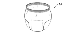
図1乃至図8を参照して、本発明の実施形態に係る吸収性物品およびその製造方法について詳細に説明する。なお、実施形態の説明は、全体を通して同じ要素には同じ番号を付している。本発明の実施形態に係る吸収性物品1としては、図1に示すようなテープ型の紙おむつが例示されるが、これに限定されるものではなく、生理用ナプキン、パンティーライナー、図7に示すようなパンツ型の紙おむつ1A、図8に示すような尿取りパッド1B、その他の吸収性物品であってもよい。なお、本明細書の説明において、吸収性物品1の長手方向は、吸収性物品1が着用されたときに着用者の前後にわたる方向であり、吸収性物品1の短手方向は、長手方向に対して横又は直交する方向である。また、本明細書の説明において、体液とは、尿、血液や軟便中の水分などの体内から体外に排出された液体をいう。さらにまた、吸収性物品1の着用時とは、吸収性物品1の装着時および着用後の少なくとも一方を示す。
With reference to FIG. 1 thru | or FIG. 8, the absorbent article which concerns on embodiment of this invention, and its manufacturing method are demonstrated in detail. In the description of the embodiments, the same numbers are assigned to the same elements throughout. As the
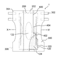
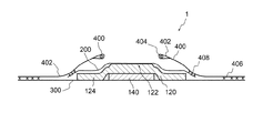
図1は、本発明の実施形態に係る吸収性物品の平面図であり、図2は、本発明の実施形態に係る吸収性物品の吸収体のみを抜き出した吸収体の平面図であり、図3は、本発明の実施形態に係る吸収性物品の断面図であって、図1のX−X’線における断面図である。図1乃至図3に示すように、吸収性物品1は、肌当接面側に配された液透過性の表面シート200と、表面シート200に対向して配置された液不透過性の防漏シート300と、表面シート200と防漏シート300との間に配置された吸収体100と、を備える。これにより、吸収体100は、表面シート200と防漏シート300の間に挟まれた構造となっている。吸収性物品1は、短手方向の端部に、長手方向に沿って設けられた立体ギャザー400を有してもよい。吸収体100は、第1の吸収部材140と第1の吸収部材140よりも肌当接面側に設けられた第2の吸収部材120とを含む複数の吸収部材を備える。第2の吸収部材120には、基底部124と、基底部124の肌当接面側の表面から突出する隆起部122と、が規定されている。隆起部122は、第2の吸収部材120の長手方向に延びるように設けられている。第1の吸収部材140は、平面視において隆起部122に重なるように配置される。図3に示すように、吸収性物品1の短手方向において、第1の吸収部材140の長さは、第2の吸収部材120の長さよりも短く設けられている。着用者の体液排出部に吸収体100をより良好に密着させつつ、優れた着用感を供するためには、隆起部122の盛り上がり量を所定量に抑える必要がある。これらによって、吸収体100に設けられた隆起部122の盛り上がり量は、第1の吸収部材140の厚み、表面積や形状によって制御可能となり、着用者の体液排出部に吸収体100をより良好に密着させて、体液の漏れを効果的に防止するとともに、優れた着用感を供することができるものである。
FIG. 1 is a plan view of an absorbent article according to an embodiment of the present invention, and FIG. 2 is a plan view of an absorbent body obtained by extracting only the absorbent body of the absorbent article according to the embodiment of the present invention. 3 is a cross-sectional view of the absorbent article according to the embodiment of the present invention, and is a cross-sectional view taken along line XX ′ of FIG. 1. As shown in FIGS. 1 to 3, the
表面シート200は、吸収体100に向けて体液を速やかに通過させるものであり、吸収体100を間にして、防漏シート300と対向して配置されている。表面シート200は、肌と当接するシートとなることから、柔らかな感触で、肌に刺激を与えないような不織布や多孔性プラスチックシートなどの材料によって形成することが好ましく、単層または複数層で設けられてもよい。表面シート200には、ドライタッチ性を付与するために多数の透孔が形成されていてもよい。不織布としては、ポリエチレンなどの合成繊維やレーヨンなどの再生繊維、綿などの天然繊維を用いて、エアスルー法、ポイントボンド法、スパンレース法やスパンボンド法などの公知の加工法によって得られたものを用いることができる。表面シート200には、撥水処理や親水処理が施されていてもよい。表面シート200は、着用者の股部が位置づけられる長手方向中央に括れ部を有する砂時計形状、略矩形形状などで設けられてよく、吸収体100の側縁より若干外方に延在して設けられてもよい。
The
防漏シート300は、吸収性物品1の外部に体液が漏れないように液不透過性を有し、遮水性を有するシート材が用いられるが、ムレ防止のために透湿性を有してもよい。このような防漏シート300の材料には、たとえば、ポリエチレンやポリエチレンラミネート不織布などの薄いプラスチックシートが挙げられる。防漏シート300は、着用者の股部が位置づけられる長手方向中央に括れ部を有する砂時計形状、略矩形形状などで設けられてよく、吸収体100の側縁より若干外方に延在して設けられてもよい。防漏シート300は、腰部304にあたる位置に、固着テープ302を有してもよいし、腰部304にあたる位置が他の腰部306と予め固着されていてもよい。図示しないが、防漏シート300の非肌当接面側には、着用時に下着などに吸収性物品を固着するための粘着剤層が設けられてもよい。粘着剤層を有する場合、さらに粘着剤層を保護し、または露出するための剥離シートを有してもよい。剥離シートは、吸収性物品の包装シートとして用いられてもよい。表面シート200と防漏シート300とは、長手方向端部などの端部の少なくとも一部において、吸収体100を挟まずに、ホットメルト接着剤やヒートシールなどにより固着されて、フラップ部202を構成してもよい。
The leak-
立体ギャザー400は、たとえば体液や便の閉じ込め空間を形成して、それらの横漏れを防止できるようになっている。立体ギャザー400は、立体ギャザーシート402と、立体ギャザーシート402の自由端部に沿って配された弾性伸縮部材404と、を備える。より詳しく説明すると、立体ギャザーシート402の短手方向の外側端部は、弾性伸縮部材404を挟んで防漏シート300にホットメルト接着剤などの固着材406によって固着され、立体ギャザーシート402の短手方向の内側端部は、平面視において吸収体100の側縁に立体ギャザーシート402が重なるように、表面シート200にホットメルト接着剤などの固着材408により固着されている。立体ギャザーシート402は、短手方向の内側端部が内折または外折に折りこまれることで、長手方向に沿って折曲部が形成されており、この折曲部に弾性伸縮部材404が挟まれている。弾性伸縮部材404は、ホットメルト接着剤などにより立体ギャザーシート402に固定されている。ここでは、立体ギャザーシート402が別部材で設けられるものを説明したが、これに限定されず、立体ギャザーシート402は、表面シート200の一部または表面シート200側に折り返した防漏シート300の一部によって構成されてもよい。また、ここでは、立体ギャザー400は、自由端部において、立体ギャザーシート402が折りこまれて二重になった例を説明したが、折りこまれずに一枚のシートにより形成されたものであってもよい。また、吸収性物品の短手方向の端部など、吸収性物品の端部の少なくとも一部において、防漏シート300と立体ギャザーシート402とはホットメルト接着剤やヒートシールによって固着されて、フラップ部を形成していてもよい。これらにより、吸収性物品1は、表面シート200、防漏シート300および立体ギャザーシート402によって、吸収体100が内包される構造となる。
The three-dimensional gather 400 forms a confinement space for bodily fluids and feces, for example, and can prevent side leakage thereof. The three-dimensional gather 400 includes a three-dimensional gather
第1の吸収部材140と第2の吸収部材120との少なくとも一方は、略砂時計形状、略矩形形状や略楕円形状など任意の形状をなし、表面シート200および防漏シート300の少なくとも一方と相似形をなしてもよい。第1の吸収部材140と第2の吸収部材120との少なくとも一方は、吸収性物品1の長手方向に延びるように設けられている。第1の吸収部材140と第2の吸収部材120とは、木材パルプや綿状繊維などの天然繊維、ポリエチレンなどからなる合成繊維、または、これらの混合物を含むマット状部材によって構成され、表面シート200や防漏シート300よりも剛性が高くなるように設けられている。
At least one of the first
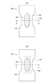
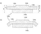
図2(a)に示すように、平面視において、第2の吸収部材の隆起部122は、第1の吸収部材140aの外形よりも大きく、第2の吸収部材の隆起部122は、第1の吸収部材140aの肌当接面側の表面を覆うように設けられていてもよい。すなわち、第2の吸収部材120は、第1の吸収部材140aに覆いかぶさるように配置される。これによって、吸収性物品1は、第1の吸収部材140aが、第2の吸収部材120を盛り上げて、隆起部122と基底部124との高低差が生じ、着用者の体液排出部に吸収体100をより良好に密着させて、吸収性物品1の外部への体液の漏れを効果的に防止することができるものである。また、図2(b)に示すように、平面視において、第1の吸収部材140bの外形は、第2の吸収部材の隆起部122よりも大きく設けられていてもよい。この場合、第1の吸収部材140bの面積が広いため、吸収力が増すこととなる。そして、図3に示すように、第1の吸収部材140の短手方向の長さと隆起部122の短手方向の長さとは、略等しく設けられてもよい。また、第1の吸収部材140の外形と隆起部122の外形とは、略同じであってもよい。隆起部122は、図1および図2に示すとおり、平面視において、略矩形形状や略楕円形状、円形形状など任意の形状に設けられてもよい。
As shown in FIG. 2A, in the plan view, the raised
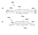
図4は、本発明の実施形態の変形例に係る吸収性物品1の吸収体100aを抜き出した吸収体100aの断面図であって、図2(a)のY−Y’線における断面図である。図4によって説明する変形例においては、上記実施形態の吸収体100の代わりに、吸収体100aを用いた以外は実施形態と同様である。図4(a)は、上記第1の吸収部材140の代わりに第1の吸収部材140aを用い、第2の吸収部材120として第2の吸収部材120aを用いて、それらを単に積み重ねた状態を示し、図4(b)は図4(a)の吸収体100aが吸収性物品1に組み込まれた状態を示す。図4に示すように、第2の吸収部材120aの隆起部122a短手方向の長さは、第1の吸収部材140aの短手方向の長さよりも大きく設けられている。また、図4に示すように、平面視において、隆起部122aの外形は、第1の吸収部材140aの外形よりも大きく設けられていることが好ましい。これによって、吸収性物品1は、第1の吸収部材140aが、隆起部122aを盛り上げるとともに、隆起部122aと基底部124aとの高低差に起因する段差を低減することができ、着用者の体液排出部に吸収体100aをより良好に密着させて、体液の漏れを効果的に防止することができる。
FIG. 4 is a cross-sectional view of the
図5は、本発明の実施形態の変形例に係る吸収性物品の吸収体のみを抜き出した吸収体の断面図であって、図2(b)のY−Y’線における断面図である。図5によって説明する変形例においては、吸収体100として、吸収体100bを用いた以外は上記実施形態と同様である。図5(a)は、上記第1の吸収部材140の代わりに第1の吸収部材140bを用い、第2の吸収部材120として第2の吸収部材120bを用いて、それらを単に積み重ねた状態を示し、図5(b)は図5(a)の吸収体100bが吸収性物品1に組み込まれた状態を示す。図5に示すように、第2の吸収部材120bの隆起部122bの短手方向の長さは、第1の吸収部材140bの短手方向の長さよりも小さく設けられ、同時に、第2の吸収部材120bの基底部124bの短手方向の長さは、相対的に小さくなっている。この場合、第1の吸収部材140bの面積が広いため、吸収力が増すこととなる。また、図5に示すように、平面視において、隆起部122bの外形は、第1の吸収部材140bの外形よりも小さく設けられてもよい。
FIG. 5 is a cross-sectional view of an absorbent body obtained by extracting only the absorbent body of an absorbent article according to a modification of the embodiment of the present invention, and is a cross-sectional view taken along line Y-Y ′ of FIG. The modification described with reference to FIG. 5 is the same as the above embodiment except that the
次に、図1乃至図3に戻って説明をすると、第1の吸収部材140および第2の吸収部材120は、例えば、木材パルプフラッフのような、フラッフのウェブの親水性繊維マトリックスにより形成することができる。ここで、フラッフとしては、木材パルプフラッフが好ましく、機械的な解繊が容易となるよう、薬剤処理したものを用いてもよい。木材パルプフラッフとしては、嵩が低く、解繊装置の所要動力(パルプをフラッフ化する際の解繊機の消費電力)が抑えられるトリートメントパルプを用いることが好ましい。また、第1の吸収部材140および第2の吸収部材120は、フラッフのウェブの親水性繊維マトリックスを高吸水性樹脂(SAP:Super absorbent Polymer)の粒子と混合して形成してもよい。高吸水性樹脂としては、例えば、ポリアクリル酸塩架橋物、自己架橋したポリアクリル酸塩、アクリル酸エステル−酢酸ビニル共重合体架橋物のケン化物、イソブチレン・無水真レイン酸共重合体架橋物、ポリスルホン酸塩架橋物や、ポリエチレンオキシド、ポリアクリルアミドなどの水膨潤性ポリマーを部分架橋したものなどが挙げられる。これらの内、高吸水性樹脂としては、吸水量、吸水速度に優れるアクリル酸またはアクリル酸塩系のものが好適である。高吸水性樹脂は、第1の吸収部材140および第2の吸収部材120の少なくともいずれか一方において、全体に均一に分散されていてもよいし、厚み方向中央部に集中して分散されていてもよい。
Next, referring back to FIGS. 1 to 3, the first
第1の吸収部材140の高吸水性樹脂の含有率は、第2の吸収部材120の高吸水性樹脂の含有率よりも大きくてもよい。これにより、吸収体100全体としての体液吸収量を維持しつつ、第2の吸収部材120の体液吸収時の膨張を低く抑えることができ、着用時の異物感を低減することができる。なお、好ましくは、第1の吸収部材140の高吸水性樹脂の含有率は45質量%以上であって60質量%以下であり、第2の吸収部材120の高吸水性樹脂の含有率は25質量%以上であって40質量%以下である。
The content of the superabsorbent resin in the first
第2の吸収部材120の基底部124には、肌当接面側の表面において、隆起部122の周縁に沿った圧搾溝が形成されていないことが好ましい。隆起部122の周縁に圧搾溝が設けられた場合には、隆起部122は綺麗に盛り上がるものの、体液吸収時の高吸水性樹脂の膨張の制御は難しく、隆起部122の盛り上がり量が甚大になる。このような吸収性物品を用いた場合、着用者に不快感と異物感を与えてしまう。従って、肌当接面側の表面において、隆起部122の周縁に沿った圧搾溝を形成せずに、第1の吸収部材140のみで隆起部122の盛り上がり量を制御することで、吸収性物品1は、着用者の体液排出部に吸収体100をより良好に密着させて、体液の漏れを効果的に防止するとともに、優れた着用感を供することができるものである。ただし、このような構成に限定されることなく、第1の吸収部材140および第2の吸収部材120の少なくとも一方には、体液の拡散吸収などのために圧搾溝が形成されていてもよいことは言うまでもない。
In the
また、上記吸収性物品の短手方向において、上記第1の吸収部材の長さは、上記第2の吸収部材の長さの30%以上であって70%以下であることが好ましい。30質量%以上とすることによって、製品状態で肌当接面側に凸上に隆起する部分が細くなりすぎ、着用者に違和感を与えてしまうことを防止できるという効果が得られ、70%以下とすることによって、股下部分全体が厚くなり、着用感が悪化することを防止することが出来るという効果が得られる。 In the short direction of the absorbent article, the length of the first absorbent member is preferably 30% or more and 70% or less of the length of the second absorbent member. By setting it as 30 mass% or more, the effect that it can prevent that the part which protrudes convexly on the skin contact surface side in a product state becomes too thin, and gives a wearer an uncomfortable feeling is acquired, and it is 70% or less. By doing this, the entire crotch part becomes thick, and the effect that it can prevent that a feeling of wear deteriorates is acquired.
さらに、図4(a)または図5(a)において示すように、第2の吸収部材120の基底部124のフラッフ目付(B)は、100g/m2以上であって200g/m2以下であり、第2の吸収部材120の隆起部122のフラッフ目付(A)は、50g/m2以上であって150g/m2以下であり、第1の吸収部材140のフラッフ目付(D)は、250g/m2以上であって400g/m2以下であり、第2の吸収部材120のフラッフ目付(C)は、150g/m2以上であって350g/m2以下であり、吸収性物品1の全体のフラッフ目付(E)は、400g/m2以上であって750g/m2以下であることが好ましい。図面の便宜上、図4(a)または図5(a)を用いて説明したが、この数値は、図1乃至図3に示す実施形態においても適用可能である。このような構成により、着用者の体液排出部に対して、吸収性物品1を良好に当接することができる。
Further, as shown in FIG. 4A or 5A, the fluff weight (B) of the
なお、吸収性物品1は、吸収体100を囲撓する被包シート(図示しない)を更に含んでもよい。被包シートは、吸収体の形状保持および体液拡散性向上のために配される。被包シートは、比較的厚手の親水性の不織布からなり、表面シート200を介して滴下、流入される体液をたとえば長手方向へ輸送、拡散し、液戻りを減少させるものである。
The
ここでは、第2の吸収部材120にのみ隆起部122が形成された例を説明したが、第1の吸収部材140にもこのような隆起部が形成されていてもよい。また、表面シート200、第1の吸収部材140、第2の吸収部材120、防漏シート300および立体ギャザーシート402を含む各構成部材は、接着剤などでそれぞれ隣接する構成との間で相互に固着されてもよい。さらにまた、吸収性物品1は、本明細書に記載した各構成部材以外の構成部材を更に含んでもよい。
Here, an example in which the raised
次に、図6を参照して、本発明の実施形態に係る吸収性物品1の製造方法を説明する。ここでは、吸収性物品1の構成部材の連続体を長手方向に搬送しながら、吸収性物品1を製造する方法を説明する。
Next, with reference to FIG. 6, the manufacturing method of the
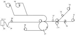
まず、積繊機11にて第1の吸収部材140を形成する。一方、第2の吸収部材120は積繊機12にて形成し、カッター13を用いて所定の形状に切断する。その際、立体形状に形成した積繊ドラムを用いることで一体の吸収部材の部分ごとに目付量を増減させて吸収部材の厚みを変化させる事により、隆起部122と基底部124とを形成する。次に、平面視において、第2の吸収部材120となる連続体の隆起部122に第1の吸収部材140が重なるように、圧縮ローラ14を用いて、第2の吸収部材120となる連続体と第1の吸収部材140とを固着する。この状態で、カッター17を用いて、切断することにより、第2の吸収部材120と第1の吸収部材140とを含む吸収体100が形成される。
First, the first
さらに長手方向に搬送されて、圧縮ローラ21において、この吸収体100の肌当接面側から、原反ロール19から給送された表面シート200となる連続体と、原反ロール20から給送された立体ギャザー400となる連続体と、を吸収体100にあてがい、この吸収体100の非肌当接面側から、原反ロール18から給送された防漏シート300となる連続体を吸収体100にあてがって、周縁をホットメルト接着剤やヒートシールによって固着するとともに、これをカッター22で切断することで吸収性物品1を形成する。その後、折り畳み機24によって、吸収性物品1を折り畳んだのちに、包装機23に給送して、複数の吸収性物品1をまとめて包装する。
Further, the sheet is conveyed in the longitudinal direction, and in the
以上、実施形態を用いて本発明を説明したが、本発明の技術的範囲は上記実施形態および実施形態に記載の範囲には限定されないことは言うまでもない。上記実施形態に、多様な変更または改良を加えることが可能であることは当業者に明らかである。また、その様な変更または改良を加えた形態も本発明の技術的範囲に含まれ得ることが、特許請求の範囲の記載から明らかである。 As mentioned above, although this invention was demonstrated using embodiment, it cannot be overemphasized that the technical scope of this invention is not limited to the range as described in the said embodiment and embodiment. It will be apparent to those skilled in the art that various modifications or improvements can be made to the above embodiment. Further, it is apparent from the description of the scope of claims that embodiments with such changes or improvements can also be included in the technical scope of the present invention.
1 吸収性物品
11,12 積繊機
18,19,20 原反ロール
13,17,22 カッター
14,21 圧縮ローラ
15 エンボスロール
23 包装機
24 折り畳み機
100,100a,100b 吸収体
120,120a,120b 第2の吸収部材
122,122a,122b 隆起部
124,124a,124b 基底部
140,140a,140b 第1の吸収部材
200 表面シート
300 防漏シート
400 立体ギャザー
402 立体ギャザーシート
404 弾性伸縮部材
406,408 固着材
DESCRIPTION OF
Claims (4)
液透過性の表面シートと、
前記表面シートに対向して配置された液不透過性の防漏シートと、
前記表面シートと前記防漏シートとの間に配置された吸収体と、
短手方向の端部に、長手方向に沿って設けられ、伸縮性弾性部材を挟み、外側端部が防漏シートに固着されたた立体ギャザーと、
を備える吸収性物品であって、
前記吸収体は、第1の吸収部材と前記第1の吸収部材よりも肌当接面側に設けられた第2の吸収部材とを備え、
前記第2の吸収部材は、基底部と、前記基底部の肌当接面側の表面から突出する隆起部であって、前記第2の吸収部材の長手方向に延びる前記隆起部を有し、
前記第1の吸収部材は、平面視において前記隆起部に重なるように配置され、
前記吸収性物品の短手方向において、前記第1の吸収部材の長さは、前記第2の吸収部材の長さよりも短く、
第1の吸収体及び第2の吸収体に、圧搾溝が形成されておらず、
第1の吸収部材の高吸水性樹脂の含有率は、45質量%以上60質量%以下であり、第2の吸収部材の高吸水性樹脂の含有率は、25質量%以上40質量%以下であり、
基底部のフラッフ目付は、100g/m 2 以上200g/m 2 以下であり、
隆起部のフラッフ目付は、50g/m 2 以上150g/m 2 以下であり、
第1の吸収部材のフラッフ目付は、250g/m 2 以上400g/m 2 以下であり、
第2の吸収部材のフラッフ目付は、150g/m 2 以上350g/m 2 以下であり、
吸収性物品の全体のフラッフ目付は、400g/m 2 以上750g/m 2 以下であることを特徴とするテープ型の使い捨て紙おむつ。 Having a longitudinal direction and a transverse direction,
A liquid-permeable surface sheet;
A liquid-impermeable leak-proof sheet disposed to face the surface sheet;
An absorbent body disposed between the top sheet and the leak-proof sheet;
Three-dimensional gathers provided along the longitudinal direction at the end in the short direction, sandwiching the elastic elastic member, and the outer end fixed to the leak-proof sheet;
An absorbent article comprising:
The absorbent body includes a first absorbent member and a second absorbent member provided on the skin contact surface side of the first absorbent member,
The second absorbent member is a basal part and a bulge part protruding from the skin contact surface side surface of the basal part, the bulge part extending in the longitudinal direction of the second absorbent member,
The first absorbent member is disposed so as to overlap the raised portion in plan view,
In the short direction of the absorbent article, the length of the first absorbent member is shorter than the length of the second absorbent member,
No compression groove is formed in the first absorber and the second absorber,
The content of the superabsorbent resin in the first absorbent member is 45% by mass or more and 60% by mass or less, and the content of the superabsorbent resin in the second absorbent member is 25% by mass or more and 40% by mass or less. Yes,
The fluff weight of the base is 100 g / m 2 or more and 200 g / m 2 or less,
The fluff weight per unit area of the raised portion is 50 g / m 2 or more and 150 g / m 2 or less,
The fluff weight of the first absorbent member is 250 g / m 2 or more and 400 g / m 2 or less,
The fluff weight of the second absorbent member is 150 g / m 2 or more and 350 g / m 2 or less,
A tape-type disposable paper diaper characterized in that the overall fluff weight of the absorbent article is 400 g / m 2 or more and 750 g / m 2 or less .
Priority Applications (1)
| Application Number | Priority Date | Filing Date | Title |
|---|---|---|---|
| JP2014098750A JP6284231B2 (en) | 2014-05-12 | 2014-05-12 | Tape-type disposable paper diapers |
Applications Claiming Priority (1)
| Application Number | Priority Date | Filing Date | Title |
|---|---|---|---|
| JP2014098750A JP6284231B2 (en) | 2014-05-12 | 2014-05-12 | Tape-type disposable paper diapers |
Publications (2)
| Publication Number | Publication Date |
|---|---|
| JP2015213651A JP2015213651A (en) | 2015-12-03 |
| JP6284231B2 true JP6284231B2 (en) | 2018-02-28 |
Family
ID=54751149
Family Applications (1)
| Application Number | Title | Priority Date | Filing Date |
|---|---|---|---|
| JP2014098750A Active JP6284231B2 (en) | 2014-05-12 | 2014-05-12 | Tape-type disposable paper diapers |
Country Status (1)
| Country | Link |
|---|---|
| JP (1) | JP6284231B2 (en) |
Families Citing this family (3)
| Publication number | Priority date | Publication date | Assignee | Title |
|---|---|---|---|---|
| MY192267A (en) | 2018-03-26 | 2022-08-15 | Essity Hygiene & Health Ab | Disposable absorbent hygiene product comprising absorbent assembly |
| MX2020009952A (en) | 2018-03-26 | 2020-10-16 | Essity Hygiene & Health Ab | Disposable absorbent hygiene product comprising absorbent assembly. |
| CN118340620B (en) * | 2024-05-22 | 2024-12-20 | 广东伊美洁健康科技有限公司 | Laminated tearable sanitary towel, preparation method and production equipment thereof |
Family Cites Families (3)
| Publication number | Priority date | Publication date | Assignee | Title |
|---|---|---|---|---|
| JP3801449B2 (en) * | 2001-02-20 | 2006-07-26 | 花王株式会社 | Absorbent articles |
| JP5800520B2 (en) * | 2010-09-16 | 2015-10-28 | ユニ・チャーム株式会社 | Body fluid absorbent article |
| JP2013074934A (en) * | 2011-09-29 | 2013-04-25 | Nippon Paper Crecia Co Ltd | Absorbent article |
-
2014
- 2014-05-12 JP JP2014098750A patent/JP6284231B2/en active Active
Also Published As
| Publication number | Publication date |
|---|---|
| JP2015213651A (en) | 2015-12-03 |
Similar Documents
| Publication | Publication Date | Title |
|---|---|---|
| WO2012029314A1 (en) | Absorbent article and sanitary napkin | |
| JP6641559B2 (en) | Absorbent articles | |
| JP2021130045A (en) | Absorbent article | |
| JP6701548B2 (en) | Absorbent article | |
| JP4746833B2 (en) | Women's incontinence pad | |
| JP6473323B2 (en) | Absorbent articles | |
| JP6284231B2 (en) | Tape-type disposable paper diapers | |
| CA2337151A1 (en) | Elastic-sided absorbent pad with soft, comfortable side panels | |
| JP6265330B2 (en) | Light incontinence products | |
| JP6761238B2 (en) | Absorbent article | |
| JP7024156B2 (en) | Absorbent article and manufacturing method of absorbent article | |
| JP6210779B2 (en) | Absorbent articles | |
| JP6756427B2 (en) | Absorbent article | |
| JP6878755B2 (en) | Absorbent auxiliary pad | |
| JP2017029242A (en) | Absorbent article | |
| JP6346059B2 (en) | Absorbent articles | |
| JP2018029868A (en) | Absorbent article | |
| JP7519200B2 (en) | Absorbent bodies and absorbent articles | |
| EP3777806B1 (en) | Absorbent article | |
| JP2019111189A (en) | Absorbent auxiliary pad | |
| JP2016209111A (en) | Absorbent article | |
| JP6946600B2 (en) | Absorbent auxiliary pad and how to use it | |
| JP2017086578A (en) | Absorbent article | |
| JP6944575B2 (en) | Absorbent article | |
| JP7379796B2 (en) | absorbent articles |
Legal Events
| Date | Code | Title | Description |
|---|---|---|---|
| A621 | Written request for application examination |
Free format text: JAPANESE INTERMEDIATE CODE: A621 Effective date: 20170501 |
|
| A977 | Report on retrieval |
Free format text: JAPANESE INTERMEDIATE CODE: A971007 Effective date: 20171208 |
|
| A131 | Notification of reasons for refusal |
Free format text: JAPANESE INTERMEDIATE CODE: A131 Effective date: 20171219 |
|
| A521 | Written amendment |
Free format text: JAPANESE INTERMEDIATE CODE: A523 Effective date: 20180110 |
|
| TRDD | Decision of grant or rejection written | ||
| A01 | Written decision to grant a patent or to grant a registration (utility model) |
Free format text: JAPANESE INTERMEDIATE CODE: A01 Effective date: 20180123 |
|
| A61 | First payment of annual fees (during grant procedure) |
Free format text: JAPANESE INTERMEDIATE CODE: A61 Effective date: 20180126 |
|
| R150 | Certificate of patent or registration of utility model |
Ref document number: 6284231 Country of ref document: JP Free format text: JAPANESE INTERMEDIATE CODE: R150 |