JP6284085B2 - Battery fixing frame member, battery fixing member, and power storage device - Google Patents

Battery fixing frame member, battery fixing member, and power storage device Download PDF

Info

Publication number
JP6284085B2
JP6284085B2 JP2015538912A JP2015538912A JP6284085B2 JP 6284085 B2 JP6284085 B2 JP 6284085B2 JP 2015538912 A JP2015538912 A JP 2015538912A JP 2015538912 A JP2015538912 A JP 2015538912A JP 6284085 B2 JP6284085 B2 JP 6284085B2
Authority
JP
Japan
Prior art keywords
battery
duct
plate
exhaust
frame
Prior art date
Legal status (The legal status is an assumption and is not a legal conclusion. Google has not performed a legal analysis and makes no representation as to the accuracy of the status listed.)
Active
Application number
JP2015538912A
Other languages
Japanese (ja)
Other versions
JPWO2015045401A1 (en
Inventor
裕史 高崎
裕史 高崎
知昌 青木
知昌 青木
Current Assignee (The listed assignees may be inaccurate. Google has not performed a legal analysis and makes no representation or warranty as to the accuracy of the list.)
Panasonic Intellectual Property Management Co Ltd
Original Assignee
Panasonic Intellectual Property Management Co Ltd
Priority date (The priority date is an assumption and is not a legal conclusion. Google has not performed a legal analysis and makes no representation as to the accuracy of the date listed.)
Filing date
Publication date
Application filed by Panasonic Intellectual Property Management Co Ltd filed Critical Panasonic Intellectual Property Management Co Ltd
Publication of JPWO2015045401A1 publication Critical patent/JPWO2015045401A1/en
Application granted granted Critical
Publication of JP6284085B2 publication Critical patent/JP6284085B2/en
Active legal-status Critical Current
Anticipated expiration legal-status Critical

Links

Images

Classifications

    • HELECTRICITY
    • H01ELECTRIC ELEMENTS
    • H01MPROCESSES OR MEANS, e.g. BATTERIES, FOR THE DIRECT CONVERSION OF CHEMICAL ENERGY INTO ELECTRICAL ENERGY
    • H01M50/00Constructional details or processes of manufacture of the non-active parts of electrochemical cells other than fuel cells, e.g. hybrid cells
    • H01M50/30Arrangements for facilitating escape of gases
    • H01M50/35Gas exhaust passages comprising elongated, tortuous or labyrinth-shaped exhaust passages
    • H01M50/367Internal gas exhaust passages forming part of the battery cover or case; Double cover vent systems
    • HELECTRICITY
    • H01ELECTRIC ELEMENTS
    • H01MPROCESSES OR MEANS, e.g. BATTERIES, FOR THE DIRECT CONVERSION OF CHEMICAL ENERGY INTO ELECTRICAL ENERGY
    • H01M50/00Constructional details or processes of manufacture of the non-active parts of electrochemical cells other than fuel cells, e.g. hybrid cells
    • H01M50/20Mountings; Secondary casings or frames; Racks, modules or packs; Suspension devices; Shock absorbers; Transport or carrying devices; Holders
    • H01M50/204Racks, modules or packs for multiple batteries or multiple cells
    • HELECTRICITY
    • H01ELECTRIC ELEMENTS
    • H01MPROCESSES OR MEANS, e.g. BATTERIES, FOR THE DIRECT CONVERSION OF CHEMICAL ENERGY INTO ELECTRICAL ENERGY
    • H01M50/00Constructional details or processes of manufacture of the non-active parts of electrochemical cells other than fuel cells, e.g. hybrid cells
    • H01M50/20Mountings; Secondary casings or frames; Racks, modules or packs; Suspension devices; Shock absorbers; Transport or carrying devices; Holders
    • H01M50/271Lids or covers for the racks or secondary casings
    • HELECTRICITY
    • H01ELECTRIC ELEMENTS
    • H01MPROCESSES OR MEANS, e.g. BATTERIES, FOR THE DIRECT CONVERSION OF CHEMICAL ENERGY INTO ELECTRICAL ENERGY
    • H01M50/00Constructional details or processes of manufacture of the non-active parts of electrochemical cells other than fuel cells, e.g. hybrid cells
    • H01M50/20Mountings; Secondary casings or frames; Racks, modules or packs; Suspension devices; Shock absorbers; Transport or carrying devices; Holders
    • H01M50/284Mountings; Secondary casings or frames; Racks, modules or packs; Suspension devices; Shock absorbers; Transport or carrying devices; Holders with incorporated circuit boards, e.g. printed circuit boards [PCB]
    • YGENERAL TAGGING OF NEW TECHNOLOGICAL DEVELOPMENTS; GENERAL TAGGING OF CROSS-SECTIONAL TECHNOLOGIES SPANNING OVER SEVERAL SECTIONS OF THE IPC; TECHNICAL SUBJECTS COVERED BY FORMER USPC CROSS-REFERENCE ART COLLECTIONS [XRACs] AND DIGESTS
    • Y02TECHNOLOGIES OR APPLICATIONS FOR MITIGATION OR ADAPTATION AGAINST CLIMATE CHANGE
    • Y02EREDUCTION OF GREENHOUSE GAS [GHG] EMISSIONS, RELATED TO ENERGY GENERATION, TRANSMISSION OR DISTRIBUTION
    • Y02E60/00Enabling technologies; Technologies with a potential or indirect contribution to GHG emissions mitigation
    • Y02E60/10Energy storage using batteries

Description

本開示は、複数の電池モジュールを一体に固定する電池固定部材を形成するために用いられる電池固定用フレーム部材に関する。   The present disclosure relates to a battery fixing frame member used for forming a battery fixing member that integrally fixes a plurality of battery modules.

特許文献1には、複数の電池セルをケースに収納してなる電池モジュールと、複数の電池モジュールを保持する保持体とを備える蓄電装置が記載されている。電池セルで発生したガスは、電池モジュールの下部から保持体内の排気ダクトを通じて保持体を構成する複数のパネルの隙間から放出される。   Patent Document 1 describes a power storage device that includes a battery module in which a plurality of battery cells are housed in a case, and a holding body that holds the plurality of battery modules. The gas generated in the battery cell is released from the lower part of the battery module through the gaps between the plurality of panels constituting the holder through the exhaust duct in the holder.

特開2013−105723号公報JP 2013-105723 A

複数の電池モジュールを含む蓄電装置では、電池モジュールから排出されるガスを安全な温度まで冷却するための複数の排気ダクトを設ける構造で、コスト低減を図ることが望まれる。このような蓄電装置の実現のために、複数の電池モジュールを固定する電池固定部材を形成するためのフレーム部材において、複数のダクト構造を含み、かつ、コスト低減を図ることが望まれる。   In a power storage device including a plurality of battery modules, it is desired to reduce costs by providing a plurality of exhaust ducts for cooling gas discharged from the battery modules to a safe temperature. In order to realize such a power storage device, it is desired that a frame member for forming a battery fixing member for fixing a plurality of battery modules includes a plurality of duct structures and achieves cost reduction.

本開示の一態様に係る電池固定用フレーム部材は、本体板部と、複数のダクト形成部材とを備え、複数のダクト形成部材は、本体板部の一方面側に固定され、かつ、本体板部と組み合わされることにより複数の排気ダクトを形成し、複数の排気ダクトは、複数の電池モジュール内から排出されるガスを排出するために用いられる電池固定用フレーム部材であって、本体板部の他方面側に配置される複数の電池モジュールを一体に固定する電池固定部材を形成するために用いられる電池固定用フレーム部材である。 A battery fixing frame member according to an aspect of the present disclosure includes a main body plate portion and a plurality of duct forming members, and the plurality of duct forming members are fixed to one surface side of the main body plate portion, and the main body plate. The plurality of exhaust ducts are combined with the unit to form a plurality of exhaust ducts, and the plurality of exhaust ducts are battery fixing frame members used for discharging gas discharged from the plurality of battery modules. It is a battery fixing frame member used for forming a battery fixing member that integrally fixes a plurality of battery modules arranged on the other surface side.

本開示の一態様に係る電池固定部材は、本開示の一態様に係る電池固定用フレーム部材と、電池固定用フレーム部材の両端部に、電池固定用フレーム部材に対し配置方向が異なるように結合される2つのサイドフレームと、2つのサイドフレームに掛け渡されるように固定される結合フレームと、を備える。   The battery fixing member according to one aspect of the present disclosure is coupled to the battery fixing frame member according to one aspect of the present disclosure at both ends of the battery fixing frame member so that the arrangement direction is different from the battery fixing frame member. Two side frames that are connected to each other and a coupling frame that is fixed so as to be spanned between the two side frames.

本開示の一態様に係る蓄電装置は、本開示の一態様に係る電池固定部材と、電池固定部材に固定され、排気口を有する複数の電池モジュールと、を備え、各排気ダクトは、複数の電池モジュールの少なくとも1つの電池モジュールの排気口に連通して、電池モジュール内からガスを排出する。   A power storage device according to an aspect of the present disclosure includes a battery fixing member according to an aspect of the present disclosure, and a plurality of battery modules that are fixed to the battery fixing member and have an exhaust port. Gas is discharged from the battery module in communication with the exhaust port of at least one battery module of the battery module.

本開示の一態様に係る電池固定用フレーム部材、電池固定部材、及び蓄電装置によれば、電池固定部材を形成するためのフレーム部材において、複数のダクト構造を含み、かつ、コスト低減を図れる。   According to the battery fixing frame member, the battery fixing member, and the power storage device according to one aspect of the present disclosure, the frame member for forming the battery fixing member includes a plurality of duct structures and can reduce costs.

本開示の実施形態における電池固定用フレーム部材であるダクトフレームを含む蓄電装置を示す斜視図である。It is a perspective view showing an electrical storage device containing a duct frame which is a frame member for battery fixation in an embodiment of this indication. 本開示の実施形態における図1の一部を拡大して示す斜視図である。FIG. 2 is an enlarged perspective view illustrating a part of FIG. 1 according to an embodiment of the present disclosure. 本開示の実施形態における図1のA部拡大図である。FIG. 2 is an enlarged view of a part A in FIG. 1 according to the embodiment of the present disclosure. 本開示の実施形態におけるダクトフレームを含む蓄電装置において、一部を省略して裏側から見た図である。In the electrical storage device including the duct frame in the embodiment of the present disclosure, a part of the power storage device is omitted and viewed from the back side. 本開示の実施形態におけるダクトフレームを含む蓄電装置から電池固定部材であるダクト付固定部材を取り出して一部を省略して示す斜視図である。It is a perspective view which takes out the fixing member with a duct which is a battery fixing member from the electrical storage apparatus containing the duct frame in embodiment of this indication, abbreviate | omits one part, and shows it. 本開示の実施形態におけるダクトフレームを含む蓄電装置から本体板部であるフレーム本体を取り出して示す概略斜視図である。It is a schematic perspective view which takes out and shows the frame main body which is a main-body board part from the electrical storage apparatus containing the duct frame in embodiment of this indication. 本開示の実施形態における図5のダクト付固定部材において、裏側から見た斜視図である。In the fixing member with a duct of Drawing 5 in an embodiment of this indication, it is a perspective view seen from the back side. 本開示の実施形態におけるダクト付固定部材の正面図である。It is a front view of a fixing member with a duct in an embodiment of the present disclosure. 本開示の実施形態におけるダクト付固定部材において、図8の右側面図である。FIG. 9 is a right side view of FIG. 8 in the fixing member with duct in the embodiment of the present disclosure. 本開示の実施形態におけるダクト付固定部材の背面図である。It is a rear view of the fixing member with a duct in the embodiment of the present disclosure. 本開示の実施形態におけるダクト付固定部材において、図8の左側面図である。FIG. 9 is a left side view of FIG. 8 in the fixing member with duct in the embodiment of the present disclosure. 本開示の実施形態において、最上段の電池モジュールと排気ダクトとが接続された構成を拡大して示す斜視図である。In an embodiment of this indication, it is a perspective view expanding and showing the composition where the uppermost battery module and the exhaust duct were connected. 本開示の実施形態におけるダクトフレームを含む蓄電装置から電池モジュールを取り出して示す斜視図である。It is a perspective view which takes out and shows a battery module from an electrical storage apparatus containing a duct frame in an embodiment of this indication. 本開示の実施形態における図13のB−B断面図である。FIG. 14 is a BB cross-sectional view of FIG. 13 in the embodiment of the present disclosure. 本開示の実施形態における図13のC−C断面図である。It is CC sectional drawing of FIG. 13 in embodiment of this indication. 本開示の実施形態における図13のD部拡大図である。FIG. 14 is an enlarged view of a D part in FIG. 13 in the embodiment of the present disclosure. 本開示の実施形態における図16のE−E断面図である。It is EE sectional drawing of FIG. 16 in embodiment of this indication. 本開示の実施形態における図16において、センサユニットを電池モジュールに取り付ける直前の状態を示す斜視図である。In FIG. 16 in embodiment of this indication, it is a perspective view which shows the state just before attaching a sensor unit to a battery module. 本開示の実施形態の別例の第1例の蓄電装置をケースの外側から見た斜視図である。It is the perspective view which looked at the electrical storage apparatus of the 1st example of another example of the embodiment of this indication from the outside of a case. 本開示の実施形態の別例の第1例における図19のF−F断面図である。FIG. 20 is a cross-sectional view taken along line FF in FIG. 19 in a first example of another example of the embodiment of the present disclosure. 本開示の実施形態の別例の第1例における図20Aに示す取っ手部材を取り出して部分的に示す斜視図である。FIG. 20B is a perspective view partially showing the handle member shown in FIG. 20A in a first example of another example of the embodiment of the present disclosure. 本開示の実施形態の別例の第2例の蓄電装置において、一部を断面にして示している図4に対応する図である。FIG. 5 is a diagram corresponding to FIG. 4, showing a part in cross-section, in a second example power storage device of another example of the embodiment of the present disclosure. 本開示の実施形態の別例の第2例における図21から吸気側整流部材を取り出して示す斜視図である。It is a perspective view which takes out and shows an inhalation | air-intake side rectification member from FIG. 21 in 2nd example of another example of embodiment of this indication. 本開示の実施形態の別例の第2例における図21から排気側整流部材を取り出して示す斜視図である。It is a perspective view which takes out and shows an exhaust side rectification member from Drawing 21 in the 2nd example of another example of an embodiment of this indication. 本開示の実施形態の別例の第3例の蓄電装置において、図1の前方から見た図に対応する図である。FIG. 9 is a diagram corresponding to a diagram viewed from the front of FIG. 1 in a third example of the power storage device of another example of the embodiment of the present disclosure. 本開示の実施形態の別例の第3例におけるフレーム排気ファンの制御方法を示すフローチャートである。14 is a flowchart illustrating a method for controlling a frame exhaust fan in a third example of another example of the embodiment of the present disclosure. 本開示の実施形態の別例の第4例の蓄電装置において、電池モジュールのバスバー接続状態を示している図4に対応する図である。FIG. 6 is a diagram corresponding to FIG. 4 showing a bus bar connection state of a battery module in a power storage device of a fourth example of another example of the embodiment of the present disclosure. 本開示の実施形態の別例の第4例における図26の裏側から見た図である。It is the figure seen from the back side of Drawing 26 in the 4th example of another example of an embodiment of this indication. 比較例の蓄電装置において、図26に対応する図である。FIG. 27 is a diagram corresponding to FIG. 26 in a power storage device of a comparative example. 比較例の蓄電装置において、図28の裏側から見た図である。FIG. 29 is a view of the power storage device of the comparative example as seen from the back side of FIG.

以下、図面を参照しながら、本開示に係る実施形態について詳細に説明する。この説明において、具体的な形状、材料、数値、方向等は、本開示の理解を容易にするための例示であって、用途、目的、仕様等に合わせて適宜変更することができる。また、以下において複数の実施形態、または変形例などが含まれる場合、複数の実施形態または変形例における各構成要素を適宜または任意に組み合わせて実施することができる。以下ではすべての図面において実質的に同様の要素に対する重複説明を省略する場合がある。   Hereinafter, embodiments according to the present disclosure will be described in detail with reference to the drawings. In this description, specific shapes, materials, numerical values, directions, and the like are examples for facilitating understanding of the present disclosure, and can be appropriately changed according to the application, purpose, specification, and the like. In addition, when a plurality of embodiments, modifications, or the like are included below, the components in the plurality of embodiments or modifications can be implemented in an appropriate or arbitrary combination. In the following description, repeated description of substantially similar elements may be omitted in all drawings.

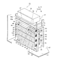
図1は本開示の実施形態における電池固定用フレーム部材であるダクトフレーム20を含む蓄電装置21を示す斜視図である。図2は、本開示の実施形態における図1の一部を拡大して示す斜視図であり、図3は、本開示の実施形態における図1のA部拡大図である。図4は、本開示の実施形態におけるダクトフレームを含む蓄電装置21において、一部を省略して裏側から見た図である。蓄電装置21は、図4に示す複数の電池モジュール22と、複数の電池モジュール22を一体に固定する電池固定部材であるダクト付固定部材24と、インバータ26、コンバータ27及び回路基板30とを含み、ケース33に収容されて構成される。図1ではケース33を破断した状態で示している。図2ではケース33を省略して示している。   FIG. 1 is a perspective view illustrating a power storage device 21 including a duct frame 20 that is a battery fixing frame member according to an embodiment of the present disclosure. FIG. 2 is an enlarged perspective view showing a part of FIG. 1 in the embodiment of the present disclosure, and FIG. 3 is an enlarged view of a portion A of FIG. 1 in the embodiment of the present disclosure. FIG. 4 is a view of a power storage device 21 including a duct frame according to an embodiment of the present disclosure, with a part omitted and viewed from the back side. The power storage device 21 includes a plurality of battery modules 22 shown in FIG. 4, a fixing member with duct 24 that is a battery fixing member that integrally fixes the plurality of battery modules 22, an inverter 26, a converter 27, and a circuit board 30. It is configured to be accommodated in the case 33. In FIG. 1, the case 33 is shown in a broken state. In FIG. 2, the case 33 is omitted.

蓄電装置21は、図示しない太陽電池等の発電装置で得られた電力を電池モジュール22に充電し、必要に応じて電池モジュール22から取り出した直流電力をコンバータ27で昇圧または降圧し、インバータ26で交流電力に変換し、図示しない電気機器に出力する機能を有する。回路基板30は、インバータ26及びコンバータ27の動作を制御する制御部を含む。蓄電装置21は、図示しないケースの内側に固定される。蓄電装置21は、発電装置からの電力を蓄電または供給するために用いられる構成に限定せず、例えば停電時または電力消費の調整に用いられてもよい。例えば蓄電装置21は、電力が分配される各建物全体で電力消費が少ない時間帯に商用交流電源から蓄電装置21に電力を蓄電し、電力消費が多い時間帯または停電時に、蓄電装置21が設置される建物内の電気機器に蓄電装置21から電力を供給してもよい。この場合、インバータ26が供給された交流電力を直流電力に変換し、変換後の直流電力を電池モジュール22に蓄電する。   The power storage device 21 charges the battery module 22 with electric power obtained by a power generation device such as a solar cell (not shown), boosts or lowers the DC power extracted from the battery module 22 as necessary, with a converter 27, and It has a function of converting to AC power and outputting it to an electric device (not shown). The circuit board 30 includes a control unit that controls operations of the inverter 26 and the converter 27. The power storage device 21 is fixed inside a case (not shown). The power storage device 21 is not limited to a configuration used to store or supply power from the power generation device, and may be used, for example, during a power failure or for adjustment of power consumption. For example, the power storage device 21 stores power from the commercial AC power source to the power storage device 21 in a time zone where power consumption is low throughout each building to which power is distributed, and the power storage device 21 is installed during a time when power consumption is high or during a power failure. Electric power may be supplied from the power storage device 21 to the electrical equipment in the building. In this case, AC power supplied from the inverter 26 is converted into DC power, and the converted DC power is stored in the battery module 22.

図1、4、及び後述する図面の一部では、互いに直交する3軸方向として、高さ方向H、長さ方向L、幅方向Wが示されている。高さ方向Hは、蓄電装置21が水平面上に設置された場合の上下方向または鉛直方向である。長さ方向L及び幅方向Wは水平面で互いに直交する方向である。ここでは蓄電装置21の寸法が長い方を長さ方向Lとし、短い方を幅方向Wとした。   In FIGS. 1 and 4 and a part of the drawings to be described later, a height direction H, a length direction L, and a width direction W are shown as three axial directions orthogonal to each other. The height direction H is a vertical direction or a vertical direction when the power storage device 21 is installed on a horizontal plane. The length direction L and the width direction W are directions orthogonal to each other on a horizontal plane. Here, the longer dimension of the power storage device 21 is defined as the length direction L, and the shorter dimension is defined as the width direction W.

次にダクト付固定部材24を説明する。図5は、本開示の実施形態におけるダクトフレームを含む蓄電装置21から、ダクト出口部材及び蓋部材を省略してダクト付固定部材24を示す斜視図である。図6は、本開示の実施形態におけるダクトフレームを含む図1からフレーム本体46を取り出して示す概略斜視図である。図7は、本開示の実施形態における図5のダクト付固定部材24において、裏側から見た斜視図である。図8、図9、図10、図11は、本開示の実施形態において、それぞれダクト付固定部材24の正面図、図8の右側面図、背面図、図8の左側面図である。   Next, the duct fixing member 24 will be described. FIG. 5 is a perspective view illustrating the fixing member 24 with the duct from which the duct outlet member and the lid member are omitted from the power storage device 21 including the duct frame according to the embodiment of the present disclosure. FIG. 6 is a schematic perspective view showing the frame body 46 taken out from FIG. 1 including the duct frame according to the embodiment of the present disclosure. FIG. 7 is a perspective view of the fixing member with duct 24 of FIG. 5 according to the embodiment of the present disclosure as viewed from the back side. 8, 9, 10, and 11 are a front view, a right side view, a rear view, and a left side view of FIG. 8, respectively, of the fixing member with duct 24 in the embodiment of the present disclosure.

ダクト付固定部材24は、ダクトフレーム20と、2つのサイドフレーム36,38と、複数の結合フレーム40,42,43,53、基板支持フレーム44、第1横プレート45a、及び第2横プレート45bとを含んで一体に固定される。2つのサイドフレーム36,38は、第1サイドフレーム36及び第2サイドフレーム38である。複数の結合フレーム40,42,43,53は、第1結合フレーム40、第2結合フレーム42、第3結合フレーム43及び第4結合フレーム53である。   The fixing member 24 with the duct includes a duct frame 20, two side frames 36, 38, a plurality of coupling frames 40, 42, 43, 53, a substrate support frame 44, a first horizontal plate 45a, and a second horizontal plate 45b. And are integrally fixed. The two side frames 36 and 38 are a first side frame 36 and a second side frame 38. The plurality of combined frames 40, 42, 43, 53 are a first combined frame 40, a second combined frame 42, a third combined frame 43, and a fourth combined frame 53.

ダクトフレーム20は、本体板部であるフレーム本体46と、複数のダクト形成部材48,50とを備える。ダクトフレーム20は、フレーム本体46の一方面側(図5の表面側)に複数のダクト形成部材48,50が上下に並んで結合固定されることにより構成される。複数のダクト形成部材48,50は、第1ダクト形成部材48及び第2ダクト形成部材50である。ダクトフレーム20は、フレーム本体46の他方面側(図5の裏面側)に配置される複数の電池モジュール22(図4)を一体に固定するダクト付固定部材24を形成するために用いられる。   The duct frame 20 includes a frame main body 46 that is a main body plate portion, and a plurality of duct forming members 48 and 50. The duct frame 20 is configured by joining and fixing a plurality of duct forming members 48 and 50 side by side on one side of the frame main body 46 (the front side in FIG. 5). The plurality of duct forming members 48 and 50 are the first duct forming member 48 and the second duct forming member 50. The duct frame 20 is used to form a fixing member with duct 24 that integrally fixes a plurality of battery modules 22 (FIG. 4) disposed on the other surface side (back surface side in FIG. 5) of the frame body 46.

フレーム本体46は、所定の外形を有する板状部材に曲げ加工と孔加工とを施すことにより形成される。図5に示すように、第1ダクト形成部材48及び第2ダクト形成部材50は、水平方向に沿う上下2つの板部である第1板部G1及び第2板部G2と、各板部G1,G2に連結され鉛直方向に沿う外側板部G3とを含む。第1ダクト形成部材48は、フレーム本体46側が開口する第1ダクト本体74と、第1ダクト本体74の両端に結合されたダクト出口部材76及び蓋部材78(図2、図3)とにより構成される。第2ダクト形成部材50は、フレーム本体46側が開口する第2ダクト本体75と、第2ダクト本体75の両端に結合されたダクト出口部材76及び蓋部材78とにより構成される。各ダクト本体74,75が、フレーム本体46の板部に開口端を塞がれて断面矩形の直線ガス流路を形成するように組み合わされることにより、上下に並んだ複数の排気ダクトである第1排気ダクト51及び複数の第2排気ダクト51A(図2、図3)が形成される。したがって、第1ダクト形成部材48及び複数の第2ダクト形成部材50は、フレーム本体46と組み合わされることにより第1排気ダクト51及び複数の第2排気ダクト51Aを形成する。各排気ダクト51,51Aは、電池モジュール22内から排出されるガスを外部に排出するために用いられる。   The frame body 46 is formed by subjecting a plate-like member having a predetermined outer shape to bending processing and hole processing. As shown in FIG. 5, the first duct forming member 48 and the second duct forming member 50 include a first plate portion G1 and a second plate portion G2, which are two upper and lower plate portions along the horizontal direction, and each plate portion G1. , G2 and an outer side plate portion G3 along the vertical direction. The first duct forming member 48 includes a first duct body 74 having an opening on the frame body 46 side, a duct outlet member 76 and lid members 78 (FIGS. 2 and 3) coupled to both ends of the first duct body 74. Is done. The second duct forming member 50 includes a second duct main body 75 that opens on the frame main body 46 side, and a duct outlet member 76 and a lid member 78 that are coupled to both ends of the second duct main body 75. The duct bodies 74 and 75 are a plurality of exhaust ducts arranged vertically by combining the duct bodies 74 and 75 so that the plate ends of the frame body 46 are closed at the open ends to form a straight gas flow path having a rectangular cross section. One exhaust duct 51 and a plurality of second exhaust ducts 51A (FIGS. 2 and 3) are formed. Accordingly, the first duct forming member 48 and the plurality of second duct forming members 50 are combined with the frame body 46 to form the first exhaust duct 51 and the plurality of second exhaust ducts 51A. Each of the exhaust ducts 51 and 51A is used to discharge gas discharged from the battery module 22 to the outside.

フレーム本体46、各ダクト本体74,75、各サイドフレーム36,38、各結合フレーム40,42,43,53、基板支持フレーム44、各横プレート45a、45bは鉄、またはアルミニウム等の金属板により形成することができる。   The frame body 46, the duct bodies 74, 75, the side frames 36, 38, the coupling frames 40, 42, 43, 53, the substrate support frame 44, and the horizontal plates 45a, 45b are made of a metal plate such as iron or aluminum. Can be formed.

図5の例では、各ダクト本体74,75を形成する第1板部G1及び第2板部G2の開口端に、曲げ形成によって各板部G1,G2に対し直角に互いに向き合うように突出する第3板部を形成し、その第3板部をフレーム本体46の一方側面に突き当てている。また、フレーム本体46において、各ダクト本体74,75の上下両側に複数のフレーム孔を形成している。そして、そのフレーム孔の内側部分をダクト本体74,75側に曲げ形成することにより得られた第1突出部114及び第2突出部116(図8)により、各ダクト形成部材48,50を上下両側から挟んでフレーム本体46に固定している。各ダクト形成部材48,50とフレーム本体46との結合構造はこのような構成に限定せず、ボルト等の結合手段、または溶接部等の接合部を用いて構成してもよい。   In the example shown in FIG. 5, the opening ends of the first plate portion G1 and the second plate portion G2 that form the duct main bodies 74 and 75 project so as to face each other at right angles to the plate portions G1 and G2 by bending. A third plate portion is formed, and the third plate portion is abutted against one side surface of the frame main body 46. In the frame body 46, a plurality of frame holes are formed on both upper and lower sides of the duct bodies 74 and 75. Then, the duct forming members 48 and 50 are moved up and down by the first projecting portion 114 and the second projecting portion 116 (FIG. 8) obtained by bending the inner portion of the frame hole to the duct main bodies 74 and 75 side. It is fixed to the frame body 46 by being sandwiched from both sides. The coupling structure between the duct forming members 48 and 50 and the frame main body 46 is not limited to such a configuration, and may be configured using a coupling means such as a bolt or a joint portion such as a welded portion.

図3に示すように、最上段の第1排気ダクト51は最上段の電池モジュール22に接続され、電池モジュール22に設けられた排気口52(図12)に第1排気ダクト51が連通する。第1排気ダクト51は、ガス下流側端部にガス下流側に向かって流路断面積が拡大する断面拡大部54が設けられる。断面拡大部54のダクト出口56周辺部に温度低下部材58が固定され、温度低下部材58の隙間を通過するガスの温度を低下させる。最上段以外の第2排気ダクト51Aはそれぞれの段の電池モジュール22に同様に接続される。各排気ダクト51,51Aの断面拡大部54は後で詳しく説明する。   As shown in FIG. 3, the uppermost first exhaust duct 51 is connected to the uppermost battery module 22, and the first exhaust duct 51 communicates with an exhaust port 52 (FIG. 12) provided in the battery module 22. The first exhaust duct 51 is provided with a cross-sectional enlarged portion 54 whose flow passage cross-sectional area increases toward the gas downstream side at the gas downstream end. A temperature reducing member 58 is fixed to the periphery of the duct outlet 56 of the cross-sectional enlarged portion 54, and the temperature of the gas passing through the gap of the temperature reducing member 58 is reduced. The second exhaust duct 51A other than the uppermost stage is similarly connected to the battery module 22 of each stage. The cross-sectional enlarged portion 54 of each exhaust duct 51, 51A will be described in detail later.

第1サイドフレーム36及び第2サイドフレーム38は、フレーム本体46の両端部に、フレーム本体46の配置方向に対しその配置方向が異なるように結合される。具体的には、各サイドフレーム36,38は、フレーム本体46の長さ方向Lの両端部にねじ止めによりフレーム本体46に対し直角に固定され、上から見た形状が門形となるように形成される。第1結合フレーム40、第2結合フレーム42、第3結合フレーム43、及び第4結合フレーム53は、第1サイドフレーム36及び第2サイドフレーム38の複数個所に長さ方向に掛け渡されて結合固定される。基板支持フレーム44は、第4結合フレーム53と、フレーム本体46とに幅方向に掛け渡されて固定される。第4結合フレーム53は、各サイドフレーム36,38の幅方向一端部(図1の裏側端部)にねじ止めにより固定される。基板支持フレーム44には、図1に示す回路基板30が固定される。   The first side frame 36 and the second side frame 38 are coupled to both ends of the frame main body 46 so that the arrangement direction thereof differs from the arrangement direction of the frame main body 46. Specifically, the side frames 36 and 38 are fixed at right angles to the frame main body 46 by screws at both ends in the length direction L of the frame main body 46 so that the shape seen from above becomes a gate shape. It is formed. The first coupling frame 40, the second coupling frame 42, the third coupling frame 43, and the fourth coupling frame 53 are coupled to each other at a plurality of locations on the first side frame 36 and the second side frame 38 in the length direction. Fixed. The substrate support frame 44 is stretched across the fourth coupling frame 53 and the frame body 46 in the width direction and fixed. The fourth coupling frame 53 is fixed to one end in the width direction of each side frame 36, 38 (back side end in FIG. 1) by screwing. The circuit board 30 shown in FIG. 1 is fixed to the board support frame 44.

第1横プレート45a及び第2横プレート45bは、第1サイドフレーム36及び第2サイドフレーム38の上端部に上下に並んで長さ方向に掛け渡され、各横プレート45a、45bの長さ方向両端部が各サイドフレーム36,38にねじ止めにより固定される。インバータ26は、上側の第1横プレート45a上に固定される。コンバータ27は、下側の第2横プレート45b上に固定される。   The first horizontal plate 45a and the second horizontal plate 45b are arranged in the longitudinal direction on the upper end portions of the first side frame 36 and the second side frame 38, and are stretched in the length direction. Both ends are fixed to the side frames 36 and 38 by screws. The inverter 26 is fixed on the upper first horizontal plate 45a. The converter 27 is fixed on the lower second horizontal plate 45b.

第1結合フレーム40及び第2結合フレーム42の少なくとも1つは、中間部の長さ方向に沿った両端が曲げ起こされることで角を持つ断面U字形の樋状に形成される。第1結合フレーム40及び第2結合フレーム42の少なくとも1つの長さ方向両端部はサイドフレーム36(または38)にねじ止めされるか、またはサイドフレーム36(または38)に形成された横孔の周縁部との係合により固定される。   At least one of the first coupling frame 40 and the second coupling frame 42 is formed in a bowl shape with a U-shaped cross section having a corner by bending both ends along the length direction of the intermediate portion. At least one longitudinal end of each of the first coupling frame 40 and the second coupling frame 42 is screwed to the side frame 36 (or 38) or a lateral hole formed in the side frame 36 (or 38). It is fixed by engagement with the peripheral edge.

図5、図6に示すように、フレーム本体46は、下端部に設けられた倒れ止め板60と、複数の電池支持板である第1電池支持板62及び第2電池支持板64と、長さ方向一端部に設けられた排出ガス遮断板66とを含んで構成される。第1電池支持板62及び第2電池支持板64は、フレーム本体46の高さ方向Hの複数個所から他方面側(図4の裏側)に突出形成される。倒れ止め板60はフレーム本体46の下端部に水平方向に曲げ起こすことにより設けられる。   As shown in FIGS. 5 and 6, the frame main body 46 includes an anti-falling plate 60 provided at the lower end, a first battery support plate 62 and a second battery support plate 64 which are a plurality of battery support plates, and a long length. And an exhaust gas blocking plate 66 provided at one end in the vertical direction. The first battery support plate 62 and the second battery support plate 64 are formed to protrude from a plurality of locations in the height direction H of the frame body 46 to the other surface side (the back side in FIG. 4). The fall-preventing plate 60 is provided at the lower end of the frame body 46 by bending it horizontally.

倒れ止め板60は、図1に示すケース33の下端に設けられた底板部67の上側にねじ止めにより固定可能である。具体的には、倒れ止め板60の複数個所には、ねじ挿入孔110が形成される。倒れ止め板60を、ねじ挿入孔110の内側に挿入されたねじ112と、図示しないナットとの結合により、倒れ止め板60の下側に配置される被固定部であるケース33の底板部67(図1)に固定される。倒れ止め板60は、フレーム本体46の図5の左側への倒れを阻止する。   The fall-preventing plate 60 can be fixed to the upper side of the bottom plate portion 67 provided at the lower end of the case 33 shown in FIG. 1 by screwing. Specifically, screw insertion holes 110 are formed at a plurality of locations on the fall-preventing plate 60. The bottom plate portion 67 of the case 33 that is a fixed portion that is disposed below the fall prevention plate 60 by coupling the fall prevention plate 60 with a screw 112 inserted inside the screw insertion hole 110 and a nut (not shown). (FIG. 1). The fall stop plate 60 prevents the frame body 46 from falling to the left in FIG.

各電池支持板62,64は、後で説明するように電池モジュール22(図1)が上側に乗せられる。排出ガス遮断板66は、フレーム本体46の長さ方向Lの一端部に高さ方向Hの全体にわたって、電池モジュール22とは反対側に直角に曲げ起こすことで形成される。排出ガス遮断板66は、各ダクト本体74,75のガス下流端部である長さ方向Lの一端部(図5の右端部)と対向するように設けられる。排出ガス遮断板66の機能は後述する。   As will be described later, the battery module 22 (FIG. 1) is placed on the battery support plates 62 and 64 on the upper side. The exhaust gas blocking plate 66 is formed at one end portion in the length direction L of the frame body 46 by bending up at a right angle on the opposite side to the battery module 22 throughout the height direction H. The exhaust gas blocking plate 66 is provided so as to face one end portion (the right end portion in FIG. 5) in the length direction L that is the gas downstream end portion of each duct body 74, 75. The function of the exhaust gas blocking plate 66 will be described later.

図4に示すように、ダクト付固定部材24には、電池モジュール22が上下方向に4段に並んで、図示しないボルト等の結合手段により固定される。電池モジュール22はボルトを用いずに、結合フレーム43(図7)とフレーム本体46とにより挟まれることで、ダクト付固定部材24に固定されてもよい。電池モジュール22は、結合フレーム40上に乗せられてもよい。   As shown in FIG. 4, the battery modules 22 are arranged on the fixing member with duct 24 in four stages in the vertical direction and fixed by a coupling means such as a bolt (not shown). The battery module 22 may be fixed to the ducted fixing member 24 by being sandwiched between the coupling frame 43 (FIG. 7) and the frame body 46 without using bolts. The battery module 22 may be placed on the coupling frame 40.

ダクト付固定部材24の最上段に1つの電池モジュール22が、2つの中段及び最下段にそれぞれ4つの電池モジュール22が固定される。そして、蓄電装置21に合計13個の電池モジュール22が配置されている。図4では電池モジュール22の後述する端子部68(図13)の図示を省略する。   One battery module 22 is fixed to the uppermost stage of the fixing member 24 with duct, and four battery modules 22 are fixed to the two middle stages and the lowermost stage, respectively. A total of 13 battery modules 22 are arranged in the power storage device 21. In FIG. 4, illustration of a terminal portion 68 (FIG. 13), which will be described later, of the battery module 22 is omitted.

各電池モジュール22は直方体状に形成されている。なお、蓄電装置21を構成する電池モジュール22の数は、13個に限定されるものではなく、蓄電装置21に要求される出力または容量に応じて適宜変更される。   Each battery module 22 is formed in a rectangular parallelepiped shape. Note that the number of battery modules 22 constituting the power storage device 21 is not limited to 13, but is appropriately changed according to the output or capacity required of the power storage device 21.

図12は、本開示の実施形態において、最上段の電池モジュール22と排気ダクト51とが接続された構成を拡大して示す斜視図である。図13は、本開示の実施形態におけるダクトフレームを含む蓄電装置から電池モジュール22を取り出して示す斜視図である。図14は、本開示の実施形態における図13のB−B断面図であり、図15は、本開示の実施形態における図13のC−C断面図である。   FIG. 12 is an enlarged perspective view showing a configuration in which the uppermost battery module 22 and the exhaust duct 51 are connected in the embodiment of the present disclosure. FIG. 13 is a perspective view illustrating the battery module 22 taken out from the power storage device including the duct frame according to the embodiment of the present disclosure. 14 is a BB cross-sectional view of FIG. 13 in the embodiment of the present disclosure, and FIG. 15 is a CC cross-sectional view of FIG. 13 in the embodiment of the present disclosure.

電池モジュール22が蓄電装置21に配置される場合に、電池モジュール22の長さ方向は蓄電装置21の幅方向Wと一致し、電池モジュール22の幅方向は蓄電装置21の長さ方向Lと一致する。電池モジュール22の長さ方向両端部には端子部68が突出形成される。2つの端子部68のうち、一方側の端子部68が正極端子であり、他方側の端子部68が負極端子である。端子部68は、電池モジュール22に含まれる最少単位の電池セルの電極に電気的に接続されて、電池セルに対し充放電を行う場合の入出力端子となる。複数の電池モジュール22の端子部68は、図示しないバスバーによって直列または並列に電気的に接続される。   When the battery module 22 is disposed in the power storage device 21, the length direction of the battery module 22 matches the width direction W of the power storage device 21, and the width direction of the battery module 22 matches the length direction L of the power storage device 21. To do. Terminal portions 68 are formed to protrude at both ends in the length direction of the battery module 22. Of the two terminal portions 68, one terminal portion 68 is a positive terminal, and the other terminal portion 68 is a negative terminal. The terminal portion 68 is electrically connected to the electrode of the minimum unit battery cell included in the battery module 22 and serves as an input / output terminal when charging / discharging the battery cell. The terminal portions 68 of the plurality of battery modules 22 are electrically connected in series or in parallel by a bus bar (not shown).

図14に示すように、電池モジュール22は、千鳥配置された複数の電池セル2を含む。図14では、複数の電池セル2を保持する後述する電池セルケース3(図15)の図示を省略する。電池モジュール22は、複数の電池セル2を並列接続して所定の電池容量が得られるように構成される。ここでは40個の電池セル2を用いた例が示される。   As shown in FIG. 14, the battery module 22 includes a plurality of battery cells 2 arranged in a staggered manner. In FIG. 14, illustration of a battery cell case 3 (FIG. 15), which will be described later, holding a plurality of battery cells 2 is omitted. The battery module 22 is configured to obtain a predetermined battery capacity by connecting a plurality of battery cells 2 in parallel. Here, an example using 40 battery cells 2 is shown.

図15に示すように、電池モジュール22は40個の電池セル2について各正極側を一方側に揃え、各負極側を他方側に揃えて所定の配置関係で整列配置される。電池モジュール22は、電池セル2、電池セルケース3、上側ホルダ6、下側ホルダ7、モジュールケース8、及びモジュールダクト19を含んで構成される。電池セルケース3は電池セル2を収納して保持し、正極側に正極側集電部4が配置され、負極側に負極側集電部5が配置される。電池セルケース3に上側ホルダ6及び下側ホルダ7を介して正極側集電部4及び負極側集電部5が結合される。なお、電池セル2が負極側から排気する構造である場合、電池モジュール22は、電池セル2について各負極側を一方側に揃え、各正極側を他方側に揃えて所定の配置関係で整列配置してもよい。   As shown in FIG. 15, the battery modules 22 are arranged in a predetermined arrangement relationship with 40 battery cells 2 such that each positive electrode side is aligned on one side and each negative electrode side is aligned on the other side. The battery module 22 includes a battery cell 2, a battery cell case 3, an upper holder 6, a lower holder 7, a module case 8, and a module duct 19. The battery cell case 3 houses and holds the battery cell 2, the positive electrode side current collector 4 is disposed on the positive electrode side, and the negative electrode side current collector 5 is disposed on the negative electrode side. A positive electrode current collector 4 and a negative electrode current collector 5 are coupled to the battery cell case 3 via an upper holder 6 and a lower holder 7. When the battery cell 2 is structured to exhaust from the negative electrode side, the battery module 22 is arranged in a predetermined arrangement relationship with the negative electrode side of the battery cell 2 aligned on one side and the positive electrode side aligned on the other side. May be.

電池セル2は、電池モジュール22を構成する電池の最小単位となる充放電可能な二次電池である。二次電池としては、リチウムイオン電池が用いられる。これ以外に、ニッケル水素電池、アルカリ電池等を用いてもよい。電池モジュール22に含まれる40個の電池セル2は、20個の電池セルを1組として、2組が横並びで配置されている。各組の電池セル2で隣接する電池セルの間の隙間を最小にする千鳥型の配置関係とされ、長さ方向Lに3列の電池列が配置され、それぞれの電池列は、幅方向Wに沿って、7個、6個、7個の電池セル2が配置されている。   The battery cell 2 is a chargeable / dischargeable secondary battery that is the minimum unit of the battery constituting the battery module 22. A lithium ion battery is used as the secondary battery. In addition, a nickel metal hydride battery, an alkaline battery, or the like may be used. Forty battery cells 2 included in the battery module 22 are arranged side by side with two sets of 20 battery cells as one set. Each set of battery cells 2 has a staggered arrangement relationship that minimizes a gap between adjacent battery cells, and three battery rows are arranged in the length direction L. 7, 6, and 7 battery cells 2 are arranged.

電池セル2は、円筒形の外形を有する。円筒形の両端部のうち一方端が正極端子、他方端が負極端子として用いられる。本実施形態では、図15に示す電池セル2の上端に正極端子が設けられ、下端に負極端子が設けられている。なお、電池セル2は円筒形の電池に限らず、他の外形を有する電池であってもよい。   The battery cell 2 has a cylindrical outer shape. Of the both ends of the cylindrical shape, one end is used as a positive terminal and the other end is used as a negative terminal. In the present embodiment, a positive electrode terminal is provided at the upper end of the battery cell 2 shown in FIG. 15, and a negative electrode terminal is provided at the lower end. The battery cell 2 is not limited to a cylindrical battery, and may be a battery having another external shape.

電池セル2は、正極端子側に安全弁13を有する。安全弁13は、電池セル2の内部で行われる電気化学反応によって発生するガスの圧力が予め定めた閾値圧力を超えたときに、電池内部からセル外部に排ガスとして放出する機能を有する。安全弁13は、ガス圧が閾値圧力を超えた時に破断される金属シート、または閾値圧力を超えたときに弁座から離れる弁体を含む構成としてもよい。   The battery cell 2 has a safety valve 13 on the positive electrode terminal side. The safety valve 13 has a function of discharging as exhaust gas from the inside of the battery to the outside of the cell when the pressure of the gas generated by the electrochemical reaction performed inside the battery cell 2 exceeds a predetermined threshold pressure. The safety valve 13 may include a metal sheet that is broken when the gas pressure exceeds a threshold pressure, or a valve body that leaves the valve seat when the gas pressure exceeds the threshold pressure.

電池セルケース3は、40個の電池セル2を所定の配置関係で整列配置して保持する保持容器である。電池セルケース3は、電池セル2の高さと同じ高さを有し、高さ方向Hの両端側がそれぞれ開口する40個の貫通孔形状の電池収納部が設けられる枠体で、それぞれの電池セル2は、電池収納部の1つに収納配置される。   The battery cell case 3 is a holding container that holds and arranges 40 battery cells 2 in a predetermined arrangement relationship. The battery cell case 3 is a frame body having the same height as the battery cell 2 and provided with 40 through-hole shaped battery storage portions that are open at both ends in the height direction H. 2 is stored and arranged in one of the battery storage units.

電池収納部の配置は、電池セル2の配置関係に対応して、千鳥型の配置関係とされる。すなわち、横並びに2組が配置され、各組で長さ方向Lに3列の電池収納部が配置され、それぞれの電池収納部列は、幅方向Wに沿って、7個、6個、7個の電池収納部を有する。かかる電池セルケース3としては、熱伝導性のよい材料であればよい。例えば、アルミニウムを主材料として、押出成形によって所定の形状としたものを用いることができる。   The arrangement of the battery storage units is a staggered arrangement relationship corresponding to the arrangement relationship of the battery cells 2. That is, two sets are arranged side by side, and three battery storage portions are arranged in the length direction L in each set, and each of the battery storage portion rows is 7, 6, and 7 along the width direction W. It has a battery storage part. The battery cell case 3 may be any material having good thermal conductivity. For example, what made aluminum the main material and was made into the predetermined shape by extrusion molding can be used.

電池セルケース3において、40個の電池セル2が電池収納部に収納配置される際に、電池セル2の各正極側が一方側に揃えられ、各負極側が他方側に揃えられる。図15では、一方側は高さ方向Hに沿って紙面の上方側で、他方側は高さ方向Hに沿って紙面の下方側である。なお、電池セルケースは、20個の電池収容部を有し互いに分離される横並びの2組の電池セルケースにより構成されてもよい。   In the battery cell case 3, when 40 battery cells 2 are housed and arranged in the battery housing portion, each positive electrode side of the battery cell 2 is aligned on one side, and each negative electrode side is aligned on the other side. In FIG. 15, one side is the upper side of the paper surface along the height direction H, and the other side is the lower side of the paper surface along the height direction H. The battery cell case may be constituted by two sets of battery cell cases that are arranged side by side and have 20 battery accommodating portions.

正極側集電部4は、電池セルケース3の一方側の開口を塞ぐように配置されて、整列配置された電池セル2の正極側をそれぞれ電気的に接続する接続部材である。正極側集電部4は、正極側絶縁板10、正極板11、正極リード板12で構成される。   The positive electrode side current collector 4 is a connecting member that is disposed so as to close the opening on one side of the battery cell case 3 and electrically connects the positive electrode sides of the aligned battery cells 2. The positive electrode side current collector 4 includes a positive electrode side insulating plate 10, a positive electrode plate 11, and a positive electrode lead plate 12.

正極側絶縁板10は、電池セルケース3と正極板11、正極リード板12との間に配置され、これらの間を電気的に絶縁する板材である。正極側絶縁板10には、電池セル2の正極電極を突き出させる40個の円形等の開口が設けられる。かかる正極側絶縁板10としては、所定の耐熱性と電気絶縁性とを有する樹脂成型品または樹脂シートを所定の形状に加工したものが用いられる。   The positive electrode-side insulating plate 10 is a plate material that is disposed between the battery cell case 3, the positive electrode plate 11, and the positive electrode lead plate 12 and electrically insulates them. The positive electrode-side insulating plate 10 is provided with 40 circular openings or the like for protruding the positive electrode of the battery cell 2. As the positive electrode-side insulating plate 10, a resin molded product or resin sheet having predetermined heat resistance and electrical insulation is processed into a predetermined shape.

正極板11は、電池セル2の正極電極にそれぞれ個別に接触する位置関係で配置される40個の電極接触部を有する薄板である。かかる正極板11としては、電気的導電性を有する金属薄板について、エッチングまたはプレス加工等によって、周囲に略C字状の切欠部が形成された所定形状の電極接触部を形成したものを用いることができる。   The positive electrode plate 11 is a thin plate having 40 electrode contact portions that are arranged in a positional relationship in which they individually contact the positive electrode of the battery cell 2. As the positive electrode plate 11, a metal thin plate having electrical conductivity formed by forming an electrode contact portion having a predetermined shape with a substantially C-shaped notch formed around by etching or pressing is used. Can do.

正極リード板12は、正極板11と電気的に接続され、40個の電極接触部を相互接続して少なくとも1つの正極側出力端子とする電極板である。かかる正極リード板12としては、電気的導電性を有し、適当な厚さと強度を有する金属薄板を用いることができる。正極リード板12としては、金属薄板についてエッチングまたはプレス加工等で、円形等の開口が形成された所定形状の電極接触部を形成したものを用いることができる。   The positive electrode lead plate 12 is an electrode plate that is electrically connected to the positive electrode plate 11 and interconnects 40 electrode contact portions to form at least one positive electrode side output terminal. As the positive electrode lead plate 12, a metal thin plate having electrical conductivity and having an appropriate thickness and strength can be used. As the positive electrode lead plate 12, a thin metal plate formed by etching or pressing or the like and having an electrode contact portion having a predetermined shape in which a circular opening or the like is formed can be used.

負極側集電部5は、電池セルケース3の他方側の開口に配置され、整列配置された電池セル2の負極側をそれぞれ電気的に接続する接続部材である。負極側集電部5は、負極側絶縁板16、負極板17、負極リード板18で構成される。   The negative electrode side current collector 5 is a connecting member that is disposed in the opening on the other side of the battery cell case 3 and electrically connects the negative electrode sides of the aligned battery cells 2. The negative electrode current collector 5 includes a negative electrode insulating plate 16, a negative electrode plate 17, and a negative electrode lead plate 18.

負極側絶縁板16は、電池セルケース3と負極板17、負極リード板18との間に配置され、これらの間を電気的に絶縁する板材である。負極側絶縁板16には、電池セル2の負極電極を露出させる40個の円形等の開口が設けられる。かかる負極側絶縁板16としては、所定の耐熱性と電気絶縁性とを有する樹脂成型品または樹脂シートを所定の形状に加工したものが用いられる。   The negative electrode side insulating plate 16 is a plate material that is disposed between the battery cell case 3, the negative electrode plate 17, and the negative electrode lead plate 18 and electrically insulates them. The negative electrode side insulating plate 16 is provided with 40 circular openings for exposing the negative electrode of the battery cell 2. As the negative electrode side insulating plate 16, a resin molded product or resin sheet having predetermined heat resistance and electrical insulation is processed into a predetermined shape.

負極板17は、電池セル2の負極電極にそれぞれ個別に接触する位置関係で配置される40個の電極接触部を有する電極部材である。かかる負極板17としては、電気的導電性を有する金属薄板について、エッチングまたはプレス加工等によって、略C字状の切欠部を形成することにより区画された電極接触部を形成したものを用いることができる。また、負極板17の電極接触部には、電池セル2に過電流が流れることで予め定めた閾値温度を超えるときに溶断する電流遮断素子を設けてもよい。   The negative electrode plate 17 is an electrode member having 40 electrode contact portions that are arranged in a positional relationship in contact with the negative electrode of the battery cell 2. As the negative electrode plate 17, a thin metal plate having electrical conductivity formed by forming a substantially C-shaped notch portion by etching or pressing or the like to form a partitioned electrode contact portion is used. it can. The electrode contact portion of the negative electrode plate 17 may be provided with a current interrupting element that blows when an overcurrent flows through the battery cell 2 and exceeds a predetermined threshold temperature.

負極リード板18は、負極板17と電気的に接続され、40個の電極接触部のそれぞれを相互接続して少なくとも1つの負極側出力端子とする電極板である。かかる負極リード板18としては、電気的導電性を有し、適当な厚さと強度を有する金属薄板を、エッチングまたはプレス加工等で、負極板17の電極接触部に対応して円形等の開口が形成されたものを用いることができる。   The negative electrode lead plate 18 is an electrode plate that is electrically connected to the negative electrode plate 17 and interconnects each of the 40 electrode contact portions to form at least one negative electrode side output terminal. As the negative electrode lead plate 18, a metal thin plate having electrical conductivity and having an appropriate thickness and strength is formed by opening or opening a circle or the like corresponding to the electrode contact portion of the negative electrode plate 17 by etching or pressing. The formed one can be used.

上側ホルダ6及び下側ホルダ7は、電池セルケース3の一方側に配置される正極側集電部4と他方側に配置される負極側集電部5とを、電池セルケース3とともに、全体として一体化するための部材で、絶縁材料で構成される。例えば上側ホルダ6及び下側ホルダ7は、正極側集電部4と負極側集電部5とを、ボルト等の締結部材を用いて締結して一体化される。なお、ホルダは別々に構成されていなくてもよく、例えば、電池セルケース3の側面を覆う側部と、正極側を覆う上部と、負極側を覆う下部とが一体に構成されてもよい。各ホルダ6,7は、モジュールケース8の内側に固定され、モジュールケース8は、上側のダクトカバー14と下側のボトムカバー15とにより構成される。   The upper holder 6 and the lower holder 7, together with the battery cell case 3, have a positive electrode side current collector 4 disposed on one side of the battery cell case 3 and a negative electrode side current collector 5 disposed on the other side. It is a member for integrating as an insulating material. For example, the upper holder 6 and the lower holder 7 are integrated by fastening the positive current collector 4 and the negative current collector 5 using a fastening member such as a bolt. Note that the holders may not be configured separately, and, for example, a side portion that covers the side surface of the battery cell case 3, an upper portion that covers the positive electrode side, and a lower portion that covers the negative electrode side may be integrally configured. Each holder 6, 7 is fixed inside the module case 8, and the module case 8 is constituted by an upper duct cover 14 and a lower bottom cover 15.

上記のような構成を有する電池モジュール22の上部には、内部にダクト室9を有し、下側が開口する断面U字形のモジュールダクト19が設けられる。モジュールダクト19は、上側ホルダ6の上側に被せるように設けられ、上端が枠状となるダクトカバー14の上端開口周縁部の上側に固定される。一方、負極側集電部5の下側には、ダクトカバー14に結合されたボトムカバー15が設けられる。   At the upper part of the battery module 22 having the above-described configuration, a module duct 19 having a U-shaped cross section having a duct chamber 9 therein and opened at the lower side is provided. The module duct 19 is provided so as to cover the upper side of the upper holder 6, and is fixed to the upper side of the peripheral edge of the upper end opening of the duct cover 14 whose upper end has a frame shape. On the other hand, a bottom cover 15 coupled to the duct cover 14 is provided below the negative electrode current collector 5.

ダクト室9が、安全弁13が設けられた電池セル2の正極端子に開口部または切欠部を介して臨むとともに、モジュールダクト19の長さ方向一端面に形成された排気口52(図13)に連通している。これにより、電池セル2の安全弁13から噴出したガスは、ダクト室9から排気口52を介して外部に排出可能である。後述するように、排気口52は対応する第1排気ダクト51または第2排気ダクト51Aに連通し、各電池セル2から噴出したガスは、各排気ダクト51,51Aを通じて電池モジュール22の外部に排出される。モジュールダクト19は、熱伝導性のよい材料であればよい。例えば、アルミニウムを主材料とする金属板により形成される。   The duct chamber 9 faces the positive terminal of the battery cell 2 provided with the safety valve 13 through an opening or a notch, and is connected to an exhaust port 52 (FIG. 13) formed on one end surface in the length direction of the module duct 19. Communicate. Thereby, the gas ejected from the safety valve 13 of the battery cell 2 can be discharged to the outside from the duct chamber 9 through the exhaust port 52. As will be described later, the exhaust port 52 communicates with the corresponding first exhaust duct 51 or second exhaust duct 51A, and the gas ejected from each battery cell 2 is discharged to the outside of the battery module 22 through each exhaust duct 51, 51A. Is done. The module duct 19 may be made of a material having good thermal conductivity. For example, it is formed of a metal plate whose main material is aluminum.

なお、上記では電池モジュール22として、各電池セル2が並列接続される場合を説明したが、直列接続された横並びの2組の電池セルが含まれてもよいし、あるいは直列または並列接続された3組以上の電池セルが含まれてもよい。   In addition, although the case where each battery cell 2 was connected in parallel was demonstrated as the battery module 22 above, two sets of side-by-side battery cells connected in series may be included, or connected in series or in parallel. Three or more sets of battery cells may be included.

図12に戻って、最上段の電池モジュール22には第1排気ダクト51が接続される。なお、以下では、最上段の電池モジュール22と第1排気ダクト51との関係を説明するが、上下2つの中段及び最下段の電池モジュール22と第2排気ダクト51A(図1)との関係も、1つの第2排気ダクト51Aに連通する電池モジュール22の排気口の数が増えるだけで同様である。第2排気ダクト51Aの長さは、第1排気ダクト51の長さよりも大きい。   Returning to FIG. 12, the first exhaust duct 51 is connected to the uppermost battery module 22. In the following, the relationship between the uppermost battery module 22 and the first exhaust duct 51 will be described, but the relationship between the upper and lower two middle and lowermost battery modules 22 and the second exhaust duct 51A (FIG. 1) is also described. The same is true only when the number of exhaust ports of the battery module 22 communicating with one second exhaust duct 51A is increased. The length of the second exhaust duct 51 </ b> A is larger than the length of the first exhaust duct 51.

電池モジュール22は、フレーム本体46に結合されている。フレーム本体46において、電池モジュール22の下端部と対向する部分に矩形状の第1孔70が形成され、その第1孔70の内側部分の矩形状の板部を電池モジュール22側に略直角に折り曲げることにより、第1電池支持板62が形成されている。図6に示す第2電池支持板64は、中段及び最下段の複数の電池モジュール22の下端部と対向する部分において、第1電池支持板62よりも長くなるように形成される。各電池支持板62,64には電池モジュール22が上側に乗せられ、電池モジュール22の支持強度を高くする。また、電池モジュール22の端子部68は、フレーム本体46に形成された第2孔72を通じてフレーム本体46の片側(図8の表側)に導出される。また、図13に示すように、複数の電池モジュール22の少なくとも1つの幅方向一端部(図13の右端部)には、電池セルケース3に接触して温度を検出するセンサユニット120がモジュールケース8に対し着脱可能に装着されている。これについては後で説明する。   The battery module 22 is coupled to the frame body 46. In the frame body 46, a rectangular first hole 70 is formed in a portion facing the lower end portion of the battery module 22, and the rectangular plate portion of the inner portion of the first hole 70 is substantially perpendicular to the battery module 22 side. The first battery support plate 62 is formed by bending. The second battery support plate 64 shown in FIG. 6 is formed to be longer than the first battery support plate 62 at a portion facing the lower end portions of the middle and lowermost battery modules 22. The battery module 22 is placed on the battery support plates 62 and 64 to increase the support strength of the battery module 22. Further, the terminal portion 68 of the battery module 22 is led out to one side (front side in FIG. 8) of the frame main body 46 through the second hole 72 formed in the frame main body 46. Further, as shown in FIG. 13, at least one width direction one end portion (the right end portion in FIG. 13) of the plurality of battery modules 22 is provided with a sensor unit 120 that contacts the battery cell case 3 and detects temperature. 8 is detachably mounted. This will be described later.

第1排気ダクト51は、断面矩形の直線状の第1ダクト本体74と、第1ダクト本体74の長さ方向一端部及び他端部にそれぞれ接続されるダクト出口部材76及び蓋部材78と、ダクト出口部材76に固定された温度低下部材58(図3)とを含んで構成される。   The first exhaust duct 51 includes a linear first duct body 74 having a rectangular cross section, a duct outlet member 76 and a lid member 78 connected to one end and the other end in the length direction of the first duct body 74, respectively. And a temperature lowering member 58 (FIG. 3) fixed to the duct outlet member 76.

図12に示すように、第1ダクト本体74のフレーム本体46側の開口は、フレーム本体46に形成されたプレート孔84(図6)を介して電池モジュール22の排気口52に連通する。   As shown in FIG. 12, the opening on the frame body 46 side of the first duct body 74 communicates with the exhaust port 52 of the battery module 22 through a plate hole 84 (FIG. 6) formed in the frame body 46.

ダクト出口部材76は、長さ方向に対し直交する平面についての流路断面積SAがガス下流側に向かって徐々に拡大する形状を有する断面拡大部54を含む。断面拡大部54の長さ方向に対し直交する方向の断面は矩形である。具体的には、断面拡大部54は、上面P1及び下面P2、フレーム本体46と反対側の外側面P3、フレーム本体46側の内側面P4を連結することにより形成される。上面P1及び下面P2は、水平面に対し傾斜して、出口に向かうほど間隔が広がっている。外側面P3は、出口に向かうほどフレーム本体46から離れるように傾斜する。内側面P4は、フレーム本体46の側面にほぼ沿う形状としている。この結果、断面拡大部54のガス下流端であるダクト出口56の流路断面積SAは、ガス上流側に設けられる第1ダクト本体74の流路断面積SBよりも大きくなっている。   The duct outlet member 76 includes a cross-sectional enlarged portion 54 having a shape in which the flow path cross-sectional area SA about a plane orthogonal to the length direction gradually increases toward the gas downstream side. The cross section in the direction orthogonal to the length direction of the cross section enlarged portion 54 is rectangular. Specifically, the cross-sectional enlarged portion 54 is formed by connecting the upper surface P1 and the lower surface P2, the outer surface P3 opposite to the frame body 46, and the inner surface P4 on the frame body 46 side. The upper surface P1 and the lower surface P2 are inclined with respect to the horizontal plane, and the interval increases toward the outlet. The outer side surface P3 is inclined so as to be away from the frame body 46 toward the outlet. The inner side surface P4 has a shape substantially along the side surface of the frame body 46. As a result, the flow path cross-sectional area SA of the duct outlet 56 that is the gas downstream end of the cross-sectional enlarged portion 54 is larger than the flow path cross-sectional area SB of the first duct body 74 provided on the gas upstream side.

なお、断面拡大部54は、プレート本体との干渉がないのであれば、内側面P4を、高さ方向H及び長さ方向Lに沿う平面に対し、出口に向かって外側面P3との間隔がより大きくなるように傾斜させて、流路断面積SAがガス下流側に向かって、より大きくなる形状としてもよい。   If the cross-sectional enlarged portion 54 does not interfere with the plate body, the inner surface P4 is spaced from the outer surface P3 toward the outlet with respect to the plane along the height direction H and the length direction L. It is good also as a shape which inclines so that it may become larger and the flow-path cross-sectional area SA becomes larger toward the gas downstream side.

図3に示すように、温度低下部材58は、ダクト出口部材76に固定された金属製の網状部材、すなわち金網により構成される。温度低下部材58はダクト出口の周辺部、例えば流路断面が最も拡大した部分に、流路の一部を常時塞ぐように固定される。温度低下部材58は、網目の隙間に高温のガスが通過した場合に、温度低下部材58との接触によってそのガスの温度を低下させる。温度低下部材58がダクト出口56周辺部に固定された状態で、網目の隙間の合計面積が第1ダクト本体74の流路断面積S2と略同じであることが好ましい。   As shown in FIG. 3, the temperature lowering member 58 is composed of a metal mesh member fixed to the duct outlet member 76, that is, a wire mesh. The temperature lowering member 58 is fixed to a peripheral part of the duct outlet, for example, a part where the cross section of the flow path is most enlarged so as to always block a part of the flow path. When the high temperature gas passes through the mesh gap, the temperature lowering member 58 lowers the temperature of the gas by contact with the temperature lowering member 58. In a state where the temperature lowering member 58 is fixed to the periphery of the duct outlet 56, the total area of the mesh gaps is preferably substantially the same as the flow path cross-sectional area S <b> 2 of the first duct body 74.

蓋部材78は、第1ダクト本体74の長さ方向他端部の開口を塞ぐように固定される。ダクト出口部材76及び蓋部材78を樹脂により形成してもよい。   The lid member 78 is fixed so as to close the opening at the other end in the length direction of the first duct body 74. The duct outlet member 76 and the lid member 78 may be formed of resin.

一方、図1、図3に示す上下2つの中段及び最下段の電池モジュール22と第2排気ダクト51Aとの接続構造も、上記の最上段の電池モジュール22と第1排気ダクト51との接続構造の基本構成と同様である。この場合、2つの中段及び最下段の第2排気ダクト51Aには、それぞれの段で長さ方向Lに沿って並んだ複数の電池モジュール22に設けられた排気口を連通させる。図1に示すように、複数の排気ダクト51、51Aは上下に並んで平行に配置され、排気ダクト51,51Aのダクト出口は長さ方向一方端に設けられる。各ダクト出口は、フレーム本体46の長さ方向一端部に略直角に折り立てられた排出ガス遮断板66に対向する。この場合、各ダクト出口の開口端の一部のみが排出ガス遮断板66に対向してもよい。この構成によって、後述のように各排気ダクト51,51Aから排出されるガスが排出ガス遮断板66に吹き付けられ、ガスの温度が低下する。   On the other hand, the connection structure between the upper and lower two middle and lower battery modules 22 and the second exhaust duct 51A shown in FIGS. 1 and 3 is also the connection structure between the uppermost battery module 22 and the first exhaust duct 51. This is the same as the basic configuration. In this case, the exhaust ports provided in the plurality of battery modules 22 arranged along the length direction L are communicated with the two middle and lower second exhaust ducts 51A. As shown in FIG. 1, the plurality of exhaust ducts 51, 51 </ b> A are arranged in parallel in the vertical direction, and the duct outlets of the exhaust ducts 51, 51 </ b> A are provided at one end in the length direction. Each duct outlet faces an exhaust gas blocking plate 66 that is folded substantially perpendicularly to one end in the length direction of the frame body 46. In this case, only a part of the opening end of each duct outlet may face the exhaust gas blocking plate 66. With this configuration, as will be described later, the gas discharged from the exhaust ducts 51 and 51A is blown to the exhaust gas blocking plate 66, and the temperature of the gas is lowered.

次に、図13、図16から図18を用いてセンサユニット120を説明する。センサユニット120は、図4に示す複数の電池モジュール22の少なくとも1つ、例えば図4のQ1,Q2位置の2つの電池モジュール22に、温度検出用として装着される。図16は、本開示の実施形態における図13のD部拡大図である。図17は、本開示の実施形態における図16のE−E断面図である。図18は、本開示の実施形態における図16において、センサユニット120を電池モジュール22に取り付ける直前の状態を示す斜視図である。   Next, the sensor unit 120 will be described with reference to FIGS. 13 and 16 to 18. The sensor unit 120 is mounted for temperature detection on at least one of the plurality of battery modules 22 shown in FIG. 4, for example, two battery modules 22 at positions Q1 and Q2 in FIG. FIG. 16 is an enlarged view of a portion D in FIG. 13 according to the embodiment of the present disclosure. 17 is an EE cross-sectional view of FIG. 16 in the embodiment of the present disclosure. FIG. 18 is a perspective view showing a state immediately before the sensor unit 120 is attached to the battery module 22 in FIG. 16 in the embodiment of the present disclosure.

センサユニット120は、サーミスタを含むセンサ本体122と、センサ本体122に接続されたケーブル124と、センサ本体122を保持する保持部材126とを含んで構成される。図18に示すように保持部材126は、樹脂により略直方体に形成され、一方端に保持部材側突部128と他方端に第1保持部材側孔130とがそれぞれ設けられる。さらに、保持部材126の外側面(図18の表側面)に2つで1組となり互いに向き合うように突出する係止アーム132が設けられる。係止アーム132の先端内側面に凹溝が形成され、各組で凹溝が対向してケーブル124を弾性的に保持可能としている。   The sensor unit 120 includes a sensor main body 122 including a thermistor, a cable 124 connected to the sensor main body 122, and a holding member 126 that holds the sensor main body 122. As shown in FIG. 18, the holding member 126 is formed of a resin in a substantially rectangular parallelepiped shape, and is provided with a holding member side protrusion 128 at one end and a first holding member side hole 130 at the other end. Furthermore, a locking arm 132 is provided on the outer side surface (front side surface in FIG. 18) of the holding member 126 so as to project in a pair so as to face each other. A concave groove is formed on the inner surface of the front end of the locking arm 132, and the concave groove is opposed to each other so that the cable 124 can be elastically held.

図17に示すように、保持部材126の内側面側(図17の左面側)にはセンサ本体122が配置され、センサ本体122に接続されたケーブル124が弾力に抗してU字形に曲げ形成されている。ケーブル124は、保持部材126に形成された第2保持部材側孔134を通じて保持部材126の外側面(図17の右面側)に導出され、回路基板30(図1)に設けられる制御回路に接続される。   As shown in FIG. 17, the sensor main body 122 is arranged on the inner surface side (the left surface side of FIG. 17) of the holding member 126, and the cable 124 connected to the sensor main body 122 is bent and formed in a U shape against elasticity. Has been. The cable 124 is led out to the outer side surface (right side in FIG. 17) of the holding member 126 through the second holding member side hole 134 formed in the holding member 126, and is connected to a control circuit provided on the circuit board 30 (FIG. 1). Is done.

図18に示すように、モジュールケース8には、電池セルケース3が露出されるように矩形孔136が形成され、矩形孔136の互いに対向する側面に係止溝138とケース側突部140とが形成される。センサユニット120をモジュールケース8に取り付ける場合、保持部材126の保持部材側突部128を係止溝138に挿入する。そして、その状態でモジュールケース8のケース側突部140を弾性変形させて保持部材126にケース側突部140を滑らせながら、第1保持部材側孔130にケース側突部140を係合させ矩形孔136に保持部材126を挿入固定する。これによって、モジュールケース8にセンサユニット120が着脱可能に装着される。この状態でセンサ本体122は電池セルケース3の外面に接触するので温度検出が可能となる。また、ケーブル124のU字形に形成された部分は直線状に戻る方向の弾力を持つので、図17の矢印α方向にセンサ本体122が電池セルケース3に弾性的に押し付けられる。このため、センサ本体122と電池セルケース3とが離れることを防止して、温度検出精度を高くできる。また、電池セルケース3に弾性的に接着させることで、経時変化による接着力の低下を抑制でき、長期にわたって高い温度検出精度を維持できる。   As shown in FIG. 18, a rectangular hole 136 is formed in the module case 8 so that the battery cell case 3 is exposed, and a locking groove 138 and a case-side protrusion 140 are formed on the mutually opposing side surfaces of the rectangular hole 136. Is formed. When the sensor unit 120 is attached to the module case 8, the holding member side protrusion 128 of the holding member 126 is inserted into the locking groove 138. In this state, the case side protrusion 140 of the module case 8 is elastically deformed and the case side protrusion 140 is engaged with the first holding member side hole 130 while sliding the case side protrusion 140 on the holding member 126. The holding member 126 is inserted and fixed in the rectangular hole 136. As a result, the sensor unit 120 is detachably attached to the module case 8. In this state, the sensor main body 122 comes into contact with the outer surface of the battery cell case 3, so that the temperature can be detected. Further, since the U-shaped portion of the cable 124 has elasticity in a direction to return to a straight line, the sensor body 122 is elastically pressed against the battery cell case 3 in the direction of the arrow α in FIG. For this reason, it can prevent that the sensor main body 122 and the battery cell case 3 leave | separate, and can make temperature detection accuracy high. Further, by elastically bonding to the battery cell case 3, it is possible to suppress a decrease in adhesive force due to a change with time, and it is possible to maintain high temperature detection accuracy over a long period of time.

センサユニット120の検出信号は制御回路に送信される。制御回路は、検出温度が閾値温度を超える場合に、表示部またはブザー等の警告部を用いて警報発生を行ったり、蓄電装置21の動作を停止させる。なお、2つのセンサユニット120を複数の電池モジュール22のうち、最も高温となることが想定される電池モジュール22と、最も低温となることが想定される別の電池モジュール22とに装着してもよい。この場合、2つの電池モジュール22の検出温度の差が閾値温度を超えた場合に、制御回路は、上記の警報発生または蓄電装置21の動作停止との一方または両方を行う構成としてもよい。   The detection signal of the sensor unit 120 is transmitted to the control circuit. When the detected temperature exceeds the threshold temperature, the control circuit generates an alarm using a warning unit such as a display unit or a buzzer or stops the operation of the power storage device 21. Even if two sensor units 120 are attached to a battery module 22 that is assumed to be the highest temperature among the plurality of battery modules 22 and another battery module 22 that is assumed to be the lowest temperature. Good. In this case, when the difference between the detected temperatures of the two battery modules 22 exceeds the threshold temperature, the control circuit may be configured to perform one or both of the alarm generation and the operation stop of the power storage device 21.

上記のダクトフレーム20によれば、第1ダクト形成部材48及び複数の第2ダクト形成部材50は、フレーム本体46と組み合わされることにより第1排気ダクト51及び複数の第2排気ダクト51Aを形成する。このため、排気ダクトをフレーム本体と独立して形成する構造の場合と異なり、複数のダクト構造を含む構成で、コスト低減を図れる。また、ダクトフレーム20を含むダクト付固定部材24の剛性向上を図れる。   According to the duct frame 20 described above, the first duct forming member 48 and the plurality of second duct forming members 50 are combined with the frame body 46 to form the first exhaust duct 51 and the plurality of second exhaust ducts 51A. . For this reason, unlike the structure in which the exhaust duct is formed independently of the frame body, the configuration including a plurality of duct structures can reduce the cost. Further, the rigidity of the fixing member with duct 24 including the duct frame 20 can be improved.

また、ダクト付固定部材24の重量が各ダクト形成部材48,50側に片寄っている場合でも、フレーム本体46の下端部に設けられた倒れ止め板60によって、図1の左側へのダクト付固定部材24の倒れを防止できる。また、ねじ挿入孔110に挿入されたねじ112で倒れ止め板60がケース33に固定されるので、ダクト付固定部材24の振動抑制を図れる。このようにダクトフレーム20は、複数の有用な機能を合わせ持つことができる。   Further, even when the weight of the fixing member with duct 24 is shifted toward the duct forming members 48 and 50, the fixing with the duct on the left side in FIG. The collapse of the member 24 can be prevented. Further, since the fall-preventing plate 60 is fixed to the case 33 by the screws 112 inserted into the screw insertion holes 110, vibration of the fixing member with duct 24 can be suppressed. Thus, the duct frame 20 can have a plurality of useful functions.

また、上記の蓄電装置21によれば、電池モジュール22の排気口52に連通する排気ダクトであって、対応する第1排気ダクト51または第2排気ダクト51Aは、断面拡大部54と、断面拡大部54のガス下流側のダクト出口周辺部に設けられた温度低下部材58とを含む。このため、電池セル2から噴出され、電池モジュール22外に排出されるガスの温度を低下でき、かつ、電池モジュール22内のガス圧力増大を抑制できる。具体的には、蓄電装置21に含まれる電池セルの異常により内部圧力が高くなって安全弁13が作動した場合、安全弁13から噴出した高温のガスはモジュールダクト19の内側と、排気口52とを介して第1排気ダクト51に送られる。第1排気ダクト51内で図12の矢印β方向に流れたガスは断面拡大部54を通じて電池モジュール22外に排出される。この場合、ガスは、第1排気ダクト51を流れる間に第1排気ダクト51を介しての放熱で温度低下し、しかも、温度低下部材58の隙間を通過することでさらに温度低下する。このため、単純な構成で、排出ガスによる発火を防止できる。   Further, according to the power storage device 21 described above, the first exhaust duct 51 or the second exhaust duct 51 </ b> A corresponding to the exhaust port 52 of the battery module 22 includes the cross-sectional enlarged portion 54 and the cross-sectional enlarged portion. And a temperature lowering member 58 provided at the duct outlet peripheral portion on the gas downstream side of the portion 54. For this reason, the temperature of the gas ejected from the battery cell 2 and discharged to the outside of the battery module 22 can be lowered, and an increase in gas pressure in the battery module 22 can be suppressed. Specifically, when the safety valve 13 is activated due to an abnormality in a battery cell included in the power storage device 21, the high-temperature gas ejected from the safety valve 13 passes through the inside of the module duct 19 and the exhaust port 52. To the first exhaust duct 51. The gas flowing in the direction of arrow β in FIG. 12 in the first exhaust duct 51 is discharged out of the battery module 22 through the cross-sectional enlarged portion 54. In this case, while the gas flows through the first exhaust duct 51, the temperature is lowered by heat dissipation through the first exhaust duct 51, and further, the temperature is further lowered by passing through the gap of the temperature lowering member 58. For this reason, ignition by exhaust gas can be prevented with a simple configuration.

一方、温度低下部材58を備える構成でも断面拡大部54がない構成では、各排気ダクト51,51Aのダクト出口56の周辺部が温度低下部材58により塞がれることにより、ガスの圧力損失が大きくなるという問題がある。この場合には、電池モジュール22内からのガス排出性が低下する。本実施形態の蓄電装置21は、ダクト出口56周辺部に断面拡大部54を有するので、温度低下部材58を設けることでガス温度を低下でき、しかも圧力損失の増大を抑制して電池モジュール22からのガス排出性を高くできる。   On the other hand, even in the configuration including the temperature lowering member 58, in the configuration without the cross-sectional enlarged portion 54, the peripheral portion of the duct outlet 56 of each of the exhaust ducts 51 and 51 </ b> A is blocked by the temperature lowering member 58, thereby causing a large gas pressure loss. There is a problem of becoming. In this case, the gas exhaustability from the inside of the battery module 22 decreases. Since the power storage device 21 of the present embodiment has the cross-sectional enlarged portion 54 around the duct outlet 56, the gas temperature can be lowered by providing the temperature lowering member 58, and the increase in pressure loss can be suppressed from the battery module 22. The gas discharge performance can be increased.

なお、上記では温度低下部材58として金網を用いる場合を説明したが、温度低下部材は、金網に限定するものではなく、断面拡大部54のガス下流側において、ガス下流側の一部を常時塞ぐように固定され、隙間を通過するガスの温度を低下できるものであればよい。例えば金属のハニカム状部材、不織布、耐火繊維のいずれか1つを温度低下部材として用いることもできる。不織布は耐火材料により形成するのがより好ましい。   In the above description, the case where a wire mesh is used as the temperature lowering member 58 has been described. However, the temperature lowering member is not limited to the wire mesh, and the gas downstream side of the cross-sectional enlarged portion 54 is always partially blocked. Any gas can be used as long as it is fixed and can lower the temperature of the gas passing through the gap. For example, any one of a metal honeycomb member, a non-woven fabric, and a refractory fiber can be used as the temperature lowering member. More preferably, the nonwoven fabric is formed of a refractory material.

また、図1、図2に示したように、各排気ダクト51,51Aのダクト出口56の少なくとも一部が排出ガス遮断板66に対向する。このため、各排気ダクト51,51Aから排出されたガスは排出ガス遮断板66に吹き付けられて温度低下する。排出ガス遮断板66がガスから伝熱された場合でも、排出ガス遮断板66は放熱性が高いので低い温度に維持される。このため、各排気ダクト51,51Aの出口に排出ガス遮断板66を介して対向する部分、例えば図示しないケースの側壁部等にユーザが手で掴む取っ手または操作部が設けられる場合でも、この取っ手または操作部の温度上昇を抑制できる。   As shown in FIGS. 1 and 2, at least a part of the duct outlet 56 of each exhaust duct 51, 51 </ b> A faces the exhaust gas blocking plate 66. For this reason, the gas discharged from the exhaust ducts 51 and 51A is blown to the exhaust gas blocking plate 66 and the temperature is lowered. Even when the exhaust gas blocking plate 66 is transferred from the gas, the exhaust gas blocking plate 66 is maintained at a low temperature because of its high heat dissipation. For this reason, even when a handle or an operation unit that is gripped by a user is provided at a portion facing the outlet of each of the exhaust ducts 51 and 51A through the exhaust gas blocking plate 66, for example, a side wall of a case (not shown), the handle Or the temperature rise of an operation part can be controlled.

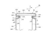
図19は、本開示の実施形態の別例の第1例の蓄電装置21をケース33の外側から見た斜視図である。図20Aは本開示の実施形態の別例の第1例における図19のF−F断面図であり、図20Bは本開示の実施形態の別例の第1例における図20Aに示す取っ手部材150を取り出して部分的に示す斜視図である。   FIG. 19 is a perspective view of the power storage device 21 of the first example of another example of the embodiment of the present disclosure as viewed from the outside of the case 33. 20A is a cross-sectional view taken along line FF in FIG. 19 in a first example of another example of the embodiment of the present disclosure, and FIG. 20B is a handle member 150 illustrated in FIG. 20A in a first example of another example of the embodiment of the present disclosure. It is a perspective view which takes out and shows partially.

蓄電装置21は、ケース33と、ケース33に収容され、複数の電池モジュール22(図1)が固定されたダクト付固定部材24とを含む。図20Aではダクト付固定部材24を模式的に示している。ケース33は、上端に開口部を有する箱状に形成されるケース本体161と、ケース本体161の上端に開口部を塞ぐように結合された断面U字形の蓋部162と、2つの取っ手部材150(図20A、図20B)とを含む。ケース本体161、蓋部162、及び取っ手部材150は例えば金属板により形成される。2つの取っ手部材150は、蓋部162の幅方向W両端に設けられた第1壁部163と、ケース本体161の幅方向W両端に設けられた第2壁部164とに結合される。ケース本体161の下端部において、幅方向W両端で長さ方向Lに離れた4個所にはキャスタ輪165が支持されることにより、蓄電装置21はユーザによって移動可能に構成される。   The power storage device 21 includes a case 33 and a fixing member with duct 24 that is housed in the case 33 and to which a plurality of battery modules 22 (FIG. 1) are fixed. FIG. 20A schematically shows the duct-attached fixing member 24. The case 33 includes a case main body 161 that is formed in a box shape having an opening at the upper end, a U-shaped lid 162 that is coupled to the upper end of the case main body 161 so as to close the opening, and two handle members 150. (FIG. 20A, FIG. 20B). The case main body 161, the lid 162, and the handle member 150 are formed of, for example, a metal plate. The two handle members 150 are coupled to a first wall portion 163 provided at both ends in the width direction W of the lid portion 162 and a second wall portion 164 provided at both ends in the width direction W of the case main body 161. At the lower end of the case body 161, the caster wheels 165 are supported at four locations separated in the length direction L at both ends in the width direction W, whereby the power storage device 21 is configured to be movable by the user.

各第2壁部164の上端縁には長さ方向Lに離れて上方に突出する3つの上側突部166が形成される。第2壁部164の上端縁において、各上側突部166の間には幅方向内側(ケース33の内側)に向かって傾斜した上側板部167が形成される。各上側板部167は、後述する取っ手部168の下端部を形成する。   Three upper protrusions 166 are formed on the upper edge of each second wall 164 so as to protrude upward in the length direction L. At the upper edge of the second wall portion 164, an upper plate portion 167 that is inclined toward the inner side in the width direction (inner side of the case 33) is formed between the upper side protrusions 166. Each upper plate portion 167 forms a lower end portion of a handle portion 168 described later.

各取っ手部材150は、鉛直方向に沿う第1取っ手側板部151と、第1取っ手側板部151の長さ方向に離れた2個所に形成され、ケース33内側に向かって幅方向Wに延伸する第2取っ手側板部152と、第2取っ手側板部152の一端から下方に曲げ形成され下方に延伸する第3取っ手側板部153と、第3取っ手側板部153の下端からケース33外側に向かって傾斜する第4取っ手側板部154とを含む。第2取っ手側板部152は、第1取っ手側板部151の長さ方向に離れた2個所において、下側半部に形成された開口の内側部分をケース33内側に曲げ形成することにより構成される。第2取っ手側板部152は、取っ手部168の上端部を形成する。取っ手部168の長さ方向両端には、ケース本体161を形成する第3壁部169が設けられ、取っ手部168の内側空間とケース33内との間の空気の流通が遮断される。   Each handle member 150 is formed at two locations separated in the length direction of the first handle side plate portion 151 along the vertical direction and the first handle side plate portion 151, and extends in the width direction W toward the inside of the case 33. 2 handle side plate portion 152, third handle side plate portion 153 bent downward from one end of second handle side plate portion 152 and extending downward, and inclined from the lower end of third handle side plate portion 153 toward the outside of case 33. 4th handle side board part 154 is included. The second handle side plate portion 152 is configured by bending the inner portion of the opening formed in the lower half portion inside the case 33 at two locations separated in the length direction of the first handle side plate portion 151. . The second handle side plate portion 152 forms the upper end portion of the handle portion 168. A third wall portion 169 that forms the case main body 161 is provided at both ends in the length direction of the handle portion 168, and air flow between the inner space of the handle portion 168 and the inside of the case 33 is blocked.

各取っ手部材150の第3取っ手側板部153は、ダクト付固定部材24に、ボルト及びナットを含む締結部170によって固定される。これによって、取っ手部材150は、重量物であるダクト付固定部材24が載置されたケース本体161を介さずに、ダクト付固定部材24に結合固定される。蓋部162は、各取っ手部材150の第1取っ手側板部151の幅方向外側(ケース33の外側)に重ねられて上側に取り付けられる。   The third handle side plate portion 153 of each handle member 150 is fixed to the fixing member with duct 24 by a fastening portion 170 including a bolt and a nut. Thus, the handle member 150 is coupled and fixed to the ducted fixing member 24 without using the case main body 161 on which the ducted fixing member 24, which is a heavy object, is placed. The lid portion 162 is attached to the upper side so as to overlap the outer side in the width direction of the first handle side plate portion 151 of each handle member 150 (outside the case 33).

各取っ手部材150は、第1取っ手側板部151の下側部分がケース本体161の上側突部166の内側に重ねられた状態でねじ部171のねじ結合によって固定される。この状態で、取っ手部材150の第4取っ手側板部154の上側にケース本体161の上側板部167が配置される。第4取っ手側板部154及び上側板部167は互いに接触させても、互いに非接触としてもよい。取っ手部材150及びケース本体161の一方または両方と、蓋部162とをねじ結合してもよい。   Each handle member 150 is fixed by screw connection of the screw portion 171 in a state where the lower portion of the first handle side plate portion 151 is overlapped with the inner side of the upper protrusion 166 of the case main body 161. In this state, the upper plate portion 167 of the case main body 161 is disposed above the fourth handle side plate portion 154 of the handle member 150. The fourth handle side plate portion 154 and the upper plate portion 167 may be in contact with each other or may not be in contact with each other. One or both of the handle member 150 and the case body 161 and the lid portion 162 may be screwed together.

ユーザが蓄電装置21を搬送する場合、取っ手部168の内側にユーザの指を挿入し、図20Aの矢印Kで示す取っ手部材150の第2取っ手側板部152の下面を持ち上げる。蓄電装置21のうち、電池モジュール22が搭載されたダクト付固定部材24は、特に重量が大きくなる場合がある。これによって、ケース本体161がダクト付固定部材24よりも剛性が低い場合には、ユーザがケース本体161を介してダクト付固定部材24を持ち上げた場合にケース33が変形する可能性がある。本例の構成によれば、ユーザは、ケース本体161を介さずにダクト付固定部材24を持ち上げることができるので、持ち上げ時にケース33に過度の負荷が加わることがなく、ケース33の変形を防止できる。   When the user transports the power storage device 21, the user's finger is inserted inside the handle portion 168, and the lower surface of the second handle side plate portion 152 of the handle member 150 indicated by the arrow K in FIG. Of the power storage device 21, the duct-equipped fixing member 24 on which the battery module 22 is mounted may be particularly heavy. Accordingly, when the case main body 161 is lower in rigidity than the fixing member 24 with duct, the case 33 may be deformed when the user lifts the fixing member 24 with duct through the case main body 161. According to the configuration of this example, the user can lift up the fixing member 24 with the duct without going through the case main body 161. Therefore, an excessive load is not applied to the case 33 during the lifting, and deformation of the case 33 is prevented. it can.

なお、ケース本体161の前側面である図19の右側面の上端部には、吸気ダクト172と、液晶部を含む操作部173とが設けられる。ケース本体161の後側面である図19の左側面の上端部には図示しない排気ダクトが設けられる。ケース33は、ケース33の下側部分を形成しダクト付固定部材24が載置される部材(本例ではケース本体161)を介さずにダクト付固定部材24に固定される取っ手部材を有する構成であればよい。取っ手部材は、ユーザに持ち上げ可能な形状を有する構成であればよい。ケース33は、図示の構成に限定しない。例えば、取っ手部は、ケース33の4個所位置に設ける構成に限定せず、幅方向W両側に1つずつまたは3つずつ以上の取っ手部が形成されてもよい。その他の構成及び作用は、図1から図18の構成と同様である場合がある。また、各取っ手部材150は、鉛直方向に沿う第1取っ手側板部151と、第1取っ手側板部151の長さ方向に離れた2個所に形成され、ケース33内側に向かって幅方向Wに延伸する第2取っ手側板部152と、第2取っ手側板部152の一端から上方に曲げ形成され上方に延伸する第3取っ手側板部153とを含んで構成されてもよい。   Note that an air intake duct 172 and an operation unit 173 including a liquid crystal unit are provided at the upper end of the right side surface of FIG. 19 which is the front side surface of the case main body 161. An exhaust duct (not shown) is provided at the upper end of the left side surface of FIG. The case 33 includes a handle member that forms a lower portion of the case 33 and is fixed to the fixing member 24 with the duct without using a member (in this example, the case main body 161) on which the fixing member 24 with the duct is placed. If it is. The handle member may be configured to have a shape that can be lifted by the user. The case 33 is not limited to the illustrated configuration. For example, the handle portion is not limited to the configuration provided at the four positions of the case 33, and one or three handle portions may be formed on both sides in the width direction W. Other configurations and operations may be the same as those in FIGS. 1 to 18. In addition, each handle member 150 is formed at two locations separated in the length direction of the first handle side plate portion 151 along the vertical direction and the first handle side plate portion 151, and extends in the width direction W toward the inside of the case 33. The second handle side plate portion 152 may be configured to include a third handle side plate portion 153 that is bent upward from one end of the second handle side plate portion 152 and extends upward.

図21は、本開示の実施形態の別例の第2例の蓄電装置21において、一部を断面にして示している図4に対応する図である。図22、23は、それぞれ本開示の実施形態の別例の第2例における図21から吸気側整流部材180、排気側整流部材183を取り出して示す斜視図である。   FIG. 21 is a diagram corresponding to FIG. 4 illustrating a part of the power storage device 21 of the second example of another example of the embodiment of the present disclosure as a cross-section. 22 and 23 are perspective views showing the intake side rectifying member 180 and the exhaust side rectifying member 183 taken out from FIG. 21 in the second example of another example of the embodiment of the present disclosure, respectively.

本例の蓄電装置21の場合、ダクト付固定部材24は、第1サイドフレーム36、第2サイドフレーム38、ダクトフレーム20(図1)、及び複数の結合フレーム40,42,43,53(図5,図7)に固定される。複数の結合フレーム40,42,43,53は、第1結合フレーム40、第2結合フレーム42、第3結合フレーム43、及び第4結合フレーム53である。ダクト付固定部材24は、金属板で形成される仕切り板186と、吸気側整流部材180及び排気側整流部材183と、フレーム排気ファン190とを含む。   In the case of the power storage device 21 of the present example, the fixing member with duct 24 includes a first side frame 36, a second side frame 38, a duct frame 20 (FIG. 1), and a plurality of coupling frames 40, 42, 43, 53 (see FIG. 5 and 7). The plurality of combined frames 40, 42, 43, 53 are a first combined frame 40, a second combined frame 42, a third combined frame 43, and a fourth combined frame 53. The fixing member with duct 24 includes a partition plate 186 formed of a metal plate, an intake side rectifying member 180 and an exhaust side rectifying member 183, and a frame exhaust fan 190.

仕切り板186は、複数の水平方向及び鉛直方向の板部を連結して形成され、ダクト付固定部材24の内側部分を、電池モジュール22側の下側空間I1と、電池モジュール22が配置されない上側空間I2とに分離するように配置される。ケース33(図19参照)内において、上側空間I2及び下側空間I1は互いに空気の流通が完全に遮断される構成に限定せず、狭い隙間、例えばケース33とダクト付固定部材24との間を通じて空気が互いに流通するようにしてもよい。また、後述する図24を用いて説明する実施形態の別例の第3例のように、電池モジュール22に接続される各排気ダクト51,51Aの排気出口は、排出ガス遮断板66の上端周辺の開口J(図2、図3参照)を介して上側空間I2に連通してもよい。なお、本例では、後述する図24の構成と同様に、各排気ダクト51、51Aの排気出口はケース33の吸気側に配置される。   The partition plate 186 is formed by connecting a plurality of horizontal and vertical plate portions, and the inner portion of the fixing member with duct 24 is arranged on the lower space I1 on the battery module 22 side and the upper side on which the battery module 22 is not disposed. It arrange | positions so that it may isolate | separate into the space I2. In the case 33 (see FIG. 19), the upper space I2 and the lower space I1 are not limited to a configuration in which the flow of air is completely blocked from each other, and a narrow gap, for example, between the case 33 and the fixing member 24 with the duct. Air may flow through each other. 24, the exhaust outlets of the exhaust ducts 51 and 51A connected to the battery module 22 are around the upper end of the exhaust gas blocking plate 66, as in a third example of another example of the embodiment described with reference to FIG. May be communicated with the upper space I2 through the opening J (see FIGS. 2 and 3). In this example, the exhaust outlets of the exhaust ducts 51 and 51A are arranged on the intake side of the case 33, as in the configuration of FIG.

上側空間I2は、上側の第1横プレート45aの上側空間である第1空間I2aと、下側の第2横プレート45bの上側空間である第2空間I2bと、第2横プレート45bの下側空間である第3空間I2cとを含む。第1空間I2aにはインバータ26が配置される。第2空間I2bにはコンバータ27が配置される。第3空間I2cには回路基板30が配置される。仕切り板186の一部は、電池モジュール22と回路基板30との間に配置される。   The upper space I2 includes a first space I2a that is an upper space of the upper first horizontal plate 45a, a second space I2b that is an upper space of the lower second horizontal plate 45b, and a lower side of the second horizontal plate 45b. 3rd space I2c which is space. An inverter 26 is disposed in the first space I2a. The converter 27 is arranged in the second space I2b. The circuit board 30 is disposed in the third space I2c. A part of the partition plate 186 is disposed between the battery module 22 and the circuit board 30.

インバータ26は、インバータケース191内に配置され、回路基板により形成される図示しないインバータ本体と、インバータケース191内に配置されたインバータファン192とを含む。コンバータ27は、コンバータケース193と、コンバータケース193内に配置され、回路基板により形成される図示しないコンバータ本体と、コンバータケース193内に配置されたコンバータファン194とを含む。図21では、インバータファン192及びコンバータファン194を透視して示している。インバータファン192及びコンバータファン194は、回路基板30が含む図示しない制御回路によって制御され、所定条件の成立状態に応じて駆動及び駆動停止が切り換えられる。各ケース191,193の長さ方向L両端には、各ケース191,193の内部に吸気し、または各ケース191,193内部から排気するための図示しない通気口が形成される。   The inverter 26 is disposed in the inverter case 191 and includes an inverter main body (not shown) formed by a circuit board and an inverter fan 192 disposed in the inverter case 191. Converter 27 includes a converter case 193, a converter body (not shown) that is disposed in the converter case 193 and formed by a circuit board, and a converter fan 194 that is disposed in the converter case 193. In FIG. 21, the inverter fan 192 and the converter fan 194 are shown through. The inverter fan 192 and the converter fan 194 are controlled by a control circuit (not shown) included in the circuit board 30 and are switched between driving and driving stop according to a predetermined condition. At both ends in the longitudinal direction L of each case 191, 193, vent holes (not shown) are formed for sucking air into each case 191, 193 or exhausting from inside each case 191, 193.

第2横プレート45bにおいて、コンバータ27の長さ方向両端よりも外側に外れた部分には上下に貫通する第2プレート開口195が形成される。   In the second horizontal plate 45b, a second plate opening 195 penetrating vertically is formed in a portion of the second lateral plate 45b that is outside the both ends in the length direction of the converter 27.

図22に示すように、吸気側整流部材180は、断面矩形の吸気側板枠部181と、吸気側板枠部181の内側に結合された2つの平板状の仕切り部である第1仕切り部182a及び第2仕切り部182bとを含む。上側の第1仕切り部182aは水平方向に配置され、下側の第2仕切り部182bは、水平方向に対し傾斜して配置される。吸気側整流部材180の内側空間は、第1仕切り部182a及び第2仕切り部182bによって3つの空間である第1整流空間S1、第2整流空間S2及び第3整流空間S3に分離される。下側の第2仕切り部182bは、吸気側整流部材180の最下部の第3整流空間S3の上下寸法において、後述するフレーム排気ファン190の駆動時に冷却空気の流れの上流側(図22の表側)が大きく、下流側(図22の裏側)が小さくなるように配置される。   As shown in FIG. 22, the intake-side rectifying member 180 includes an intake-side plate frame portion 181 having a rectangular cross section, and a first partition portion 182 a that is two flat-plate-like partition portions coupled to the inside of the intake-side plate frame portion 181. 2nd partition part 182b. The upper first partition part 182a is disposed in the horizontal direction, and the lower second partition part 182b is disposed to be inclined with respect to the horizontal direction. The inner space of the intake side rectifying member 180 is separated into three spaces, a first rectifying space S1, a second rectifying space S2, and a third rectifying space S3, by the first partition 182a and the second partition 182b. The lower second partitioning portion 182b is located on the upstream side of the flow of cooling air when the frame exhaust fan 190 described later is driven in the vertical dimension of the lowermost third rectifying space S3 of the intake side rectifying member 180 (the front side in FIG. 22). ) Is large and the downstream side (the back side in FIG. 22) is small.

図23に示すように、排気側整流部材183は、断面矩形の排気側板枠部184と、排気側板枠部184の内側に結合された平板状の排気側仕切り部185とを含む。排気側整流部材183の内側空間は、排気側仕切り部185によって上下2つの空間である第4整流空間E1及び第5整流空間E2に分離される。   As shown in FIG. 23, the exhaust side rectifying member 183 includes an exhaust side plate frame portion 184 having a rectangular cross section, and a flat plate-like exhaust side partition portion 185 coupled to the inside of the exhaust side plate frame portion 184. The inner space of the exhaust side rectification member 183 is separated into the fourth rectification space E1 and the fifth rectification space E2 which are upper and lower two spaces by the exhaust side partitioning portion 185.

各整流部材180,183は、例えば樹脂により一体成形される。各整流部材180,183の外周面に図示しない係止凸部が形成される。図21に示すように、吸気側整流部材180は、ダクト付固定部材24において、冷却空気の上流側端部(図21の左端部)に、ダクト付固定部材24に形成された図示しない係止孔に係止凸部を係止することにより固定される。排気側整流部材183は、ダクト付固定部材24において、冷却空気の下流側端部(図21の右端部)に、ダクト付固定部材24に形成された図示しない係止孔に係止凸部を係止することにより固定される。この状態で、各整流部材180,183の第1整流空間S1及び第4整流空間E1は第1空間I2aの両端に接続される。吸気側整流部材180の第2整流空間S2及び排気側整流部材183の第5整流空間E2は、第2空間I2bの両端に接続される。吸気側整流部材180の第3整流空間S3は、第3空間I2cの上流端に接続される。吸気側整流部材180の仕切り部182bの傾斜によって、第3空間I2cの狭い上流側部分に外気が導入されやすい。排気側整流部材183の排気側仕切り部185によって、第1空間I2a及び第2空間I2bから排気側整流部材183に排出された冷却空気が別の空間I2b(またはI2a)に逆流することを防止できる。   Each of the rectifying members 180 and 183 is integrally formed of, for example, resin. Locking convex portions (not shown) are formed on the outer peripheral surfaces of the respective rectifying members 180 and 183. As shown in FIG. 21, the intake-side rectifying member 180 has a locking member (not shown) formed on the fixing member with duct 24 at the upstream end portion (left end portion in FIG. 21) of the cooling air in the fixing member with duct 24. It is fixed by locking the locking projection in the hole. In the fixing member with duct 24, the exhaust side rectifying member 183 has a locking convex portion at a locking hole (not shown) formed in the fixing member with duct 24 at the downstream end portion of the cooling air (the right end portion in FIG. 21). It is fixed by locking. In this state, the first rectifying space S1 and the fourth rectifying space E1 of each of the rectifying members 180 and 183 are connected to both ends of the first space I2a. The second rectifying space S2 of the intake side rectifying member 180 and the fifth rectifying space E2 of the exhaust side rectifying member 183 are connected to both ends of the second space I2b. The third rectifying space S3 of the intake side rectifying member 180 is connected to the upstream end of the third space I2c. Due to the inclination of the partition portion 182b of the intake side rectifying member 180, outside air is easily introduced into the narrow upstream portion of the third space I2c. The exhaust side partitioning portion 185 of the exhaust side rectifying member 183 can prevent the cooling air discharged from the first space I2a and the second space I2b to the exhaust side rectifying member 183 from flowing back to another space I2b (or I2a). .

フレーム排気ファン190は、排気側整流部材183の内側の下流側に配置される。排気側整流部材183の第4整流空間E1及び第5整流空間E2のそれぞれにフレーム排気ファンが配置されてもよい。フレーム排気ファン190は、図示しない制御回路によって制御され、所定条件の成立状態に応じて駆動及び駆動停止が切り換えられる。   The frame exhaust fan 190 is disposed on the downstream side inside the exhaust side rectifying member 183. A frame exhaust fan may be disposed in each of the fourth rectification space E1 and the fifth rectification space E2 of the exhaust side rectification member 183. The frame exhaust fan 190 is controlled by a control circuit (not shown) and is switched between driving and stopping according to a predetermined condition.

上記の構成において、フレーム排気ファン190の駆動時には、吸気ダクト172を通じてケース33内に冷却空気として外気が導入される。導入された冷却空気は、吸気側整流部材180の分流構造によって上下に分かれて流れ、上側を流れる冷却空気は破線矢印γ1で示すように、インバータ26内部を通過する。吸気側整流部材180の下側を流れる冷却空気は破線矢印γ2、γ3で示すように、コンバータ27内部を通過する空気と、第2プレート開口195を通って回路基板30の周囲を通過する空気とに分かれて流れる。   In the above configuration, when the frame exhaust fan 190 is driven, outside air is introduced as cooling air into the case 33 through the intake duct 172. The introduced cooling air is divided into upper and lower parts by the flow dividing structure of the intake side rectifying member 180, and the cooling air flowing on the upper side passes through the inverter 26 as indicated by a broken line arrow γ1. The cooling air flowing under the intake side rectifying member 180 is air passing through the converter 27 and air passing around the circuit board 30 through the second plate opening 195, as indicated by broken arrows γ2 and γ3. Divided into flows.

回路基板30周囲を流れる空気は第2プレート開口195を通って、コンバータ27を通過した空気と合流して排気側整流部材183に送られる。排気側整流部材183に送られた冷却空気は、図示しない排気ダクトを通じてケース33外に排出される。   The air flowing around the circuit board 30 passes through the second plate opening 195, merges with the air that has passed through the converter 27, and is sent to the exhaust-side rectifying member 183. The cooling air sent to the exhaust side rectifying member 183 is discharged out of the case 33 through an exhaust duct (not shown).

上記の構成によれば、電池モジュール22が配置される下側空間I1に大量の冷却空気は導入されない。このため、フレーム排気ファン190として静粛性の高い構造、または小型の構造を用いる場合でも、インバータ26、コンバータ27、及び回路基板30が配置される上側空間I2に高い風量で冷却空気を流通させることができる。したがって、インバータ26、コンバータ27、及び回路基板30を効率よく冷却できる。インバータ26、コンバータ27、回路基板30の上下方向の配置順は図示の構成に限定するものではなく、種々の配置順を採用できる。その他の構成及び作用は、図1から図18の構成、または図19、図20の構成と同様である場合がある。   According to the above configuration, a large amount of cooling air is not introduced into the lower space I1 in which the battery module 22 is disposed. For this reason, even when a highly quiet structure or a small structure is used as the frame exhaust fan 190, the cooling air is circulated with a high air volume in the upper space I2 in which the inverter 26, the converter 27, and the circuit board 30 are arranged. Can do. Therefore, the inverter 26, the converter 27, and the circuit board 30 can be efficiently cooled. The arrangement order of the inverter 26, the converter 27, and the circuit board 30 in the vertical direction is not limited to the illustrated configuration, and various arrangement orders can be adopted. Other configurations and operations may be the same as the configurations in FIGS. 1 to 18 or the configurations in FIGS. 19 and 20.

図24は、本開示の実施形態の別例の第3例の蓄電装置21において、図1の前方から見た図に対応する図である。   FIG. 24 is a diagram corresponding to a diagram viewed from the front of FIG. 1 in the power storage device 21 of the third example of another example of the embodiment of the present disclosure.

本例の蓄電装置21は、各電池モジュール22に接続された排気ダクト51,51Aのダクト出口部材76に取り付けられた温度センサ196を含む。各ダクト出口部材76は各排気ダクト51,51Aの排気側端部に設けられる。温度センサ196は例えばサーミスタである。各温度センサ196の検出温度を表す信号は、回路基板30に設けられた制御回路を含む制御部197に送信される。図24では制御部197を模式的に矩形で示している。   The power storage device 21 of this example includes a temperature sensor 196 attached to the duct outlet member 76 of the exhaust ducts 51 and 51 </ b> A connected to each battery module 22. Each duct outlet member 76 is provided at the exhaust side end of each exhaust duct 51, 51A. The temperature sensor 196 is, for example, a thermistor. A signal representing the temperature detected by each temperature sensor 196 is transmitted to a control unit 197 including a control circuit provided on the circuit board 30. In FIG. 24, the control unit 197 is schematically shown by a rectangle.

各電池モジュール22に接続された排気ダクト51,51Aの排気出口は、ケース33の吸気側(図24の右側)端部に配置される。各排気ダクト51,51Aの排気出口は、上側の開口J(図3参照)を通じてインバータ26及びコンバータ27が配置される上側空間I2に連通する。   Exhaust outlets of the exhaust ducts 51, 51 </ b> A connected to each battery module 22 are disposed at the intake side (right side in FIG. 24) end of the case 33. The exhaust outlets of the exhaust ducts 51 and 51A communicate with the upper space I2 in which the inverter 26 and the converter 27 are disposed through the upper opening J (see FIG. 3).

制御部197は、複数の温度センサ196の検出温度のうち、少なくとも1つの温度センサ196の検出温度が予め設定された所定値TA以上である場合にフレーム排気ファン190の駆動を禁止する。所定値TAは、いずれかの電池モジュール22の電池セルの異常によって、電池モジュール22から高温のガスが排出された場合に達する温度から設定される。   The control unit 197 prohibits the driving of the frame exhaust fan 190 when the detected temperature of at least one temperature sensor 196 is equal to or higher than a predetermined value TA among the detected temperatures of the plurality of temperature sensors 196. The predetermined value TA is set from a temperature reached when high temperature gas is discharged from the battery module 22 due to an abnormality of the battery cell of any one of the battery modules 22.

図25は、本開示の実施形態の別例の第3例における図24の蓄電装置21において、フレーム排気ファン190の制御方法を示すフローチャートである。制御部197は、ステップS10(以下、ステップSは単にSという。)において、複数の温度センサ196の検出温度を取得し、S12で少なくとも1つの温度センサ196の検出温度が所定値TA以上か否かを判定する。S12の判定結果が肯定である場合、制御部197はフレーム排気ファン190の駆動を禁止する、すなわち、フレーム排気ファン190の駆動時には駆動を停止させ、フレーム排気ファン190の停止時には他の条件にかかわらず駆動停止を維持し、処理を終了する。S12の判定結果が否定である場合、S10に戻る。   FIG. 25 is a flowchart illustrating a method of controlling the frame exhaust fan 190 in the power storage device 21 of FIG. 24 in the third example of another example of the embodiment of the present disclosure. In step S10 (hereinafter, step S is simply referred to as S), the control unit 197 acquires the detected temperatures of the plurality of temperature sensors 196, and whether or not the detected temperature of at least one temperature sensor 196 is equal to or greater than a predetermined value TA in S12. Determine whether. When the determination result in S12 is affirmative, the control unit 197 prohibits the drive of the frame exhaust fan 190, that is, stops the drive when the frame exhaust fan 190 is driven, and depends on other conditions when the frame exhaust fan 190 stops. Without stopping driving, the process ends. If the determination result in S12 is negative, the process returns to S10.

S14の後のステップとして、制御部197が警告音発生、警告表示、または点灯を行う図示しない警告部を作動させて、ユーザに注意を喚起するステップを行ってもよい。例えば、警告部として操作部173(図19参照)に設けられた液晶部を用いて、液晶部に警告表示をさせてもよい。   As a step after S14, the control unit 197 may activate a warning unit (not shown) that generates a warning sound, displays a warning, or lights up to alert the user. For example, a warning display may be displayed on the liquid crystal unit using a liquid crystal unit provided in the operation unit 173 (see FIG. 19) as the warning unit.

上記の構成によれば、温度センサ196の検出温度が所定値TA以上となった場合にフレーム排気ファン190の駆動が禁止される。このため、第1排気ダクト51または第2排気ダクト51Aから高温の排出ガスが排出される場合に、その排出ガスがケース33外に勢いよく排出されることを防止できる。また、高温の排気ガスがインバータ26及びコンバータ27の内部に勢いよく通過してインバータ26及びコンバータ27の構成部品に悪影響が及ぶことを防止できる。なお、フレーム排気ファン190の代わりに、ケース33内の吸気側端部にダクト付固定部材24に固定されたフレーム吸気ファンを設けることもできる。この場合も、制御部197は、複数の温度センサ196の検出温度のうち、少なくとも1つの温度センサ196の検出温度が予め設定された所定値TA以上である場合にフレーム吸気ファンの駆動を禁止する。その他の構成及び作用は、図21から図23の構成と同様である場合がある。   According to the above configuration, driving of the frame exhaust fan 190 is prohibited when the temperature detected by the temperature sensor 196 is equal to or higher than the predetermined value TA. For this reason, when high temperature exhaust gas is discharged | emitted from the 1st exhaust duct 51 or the 2nd exhaust duct 51A, it can prevent that exhaust gas being exhausted out of the case 33 vigorously. Further, it is possible to prevent the hot exhaust gas from passing through the inverter 26 and the converter 27 vigorously and adversely affecting the components of the inverter 26 and the converter 27. Instead of the frame exhaust fan 190, a frame intake fan fixed to the duct-equipped fixing member 24 may be provided at the intake side end in the case 33. Also in this case, the control unit 197 prohibits the drive of the frame intake fan when the detected temperature of at least one temperature sensor 196 is equal to or higher than a predetermined value TA among the detected temperatures of the plurality of temperature sensors 196. . Other configurations and operations may be the same as those in FIGS. 21 to 23.

図26は、本開示の実施形態の別例の第4例の蓄電装置21において、電池モジュール22のバスバー接続状態を示している図4に対応する図である。図27は、本開示の実施形態の別例の第4例における図26の裏側から見た図である。本例の蓄電装置21では、図1から図18の構成において、複数の電池モジュール22は複数のバスバー198によって電気的に直列に接続される。複数の電池モジュール22のうち、最も正極端に配置される電池モジュール22は、最下段の長さ方向L一端(図26の右端、図27の左端)に配置される。   FIG. 26 is a diagram corresponding to FIG. 4 illustrating the bus bar connection state of the battery module 22 in the power storage device 21 of the fourth example of another example of the embodiment of the present disclosure. 27 is a diagram viewed from the back side of FIG. 26 in the fourth example of another example of the embodiment of the present disclosure. In the power storage device 21 of this example, in the configuration of FIGS. 1 to 18, the plurality of battery modules 22 are electrically connected in series by the plurality of bus bars 198. Among the plurality of battery modules 22, the battery module 22 disposed at the most positive electrode end is disposed at one end in the lowermost length direction L (the right end in FIG. 26 and the left end in FIG. 27).

一方、複数の電池モジュール22のうち、最も負極端に配置される電池モジュール22は、最上段に配置される。以下、複数の電池モジュール22には、負極端から正極端に向かって配置される順に、M1,M2・・・M13の符号を付して説明する場合がある(図28、図29も同様である)。最も正極端の電池モジュール(以下、正極端電池モジュールという。)M13は総正極端子199を有し、最も負極端の電池モジュール(以下、負極端電池モジュールという。)M1は総負極端子200を有する。総正極端子199及び総負極端子200は、回路基板30に接続される。   On the other hand, among the plurality of battery modules 22, the battery module 22 arranged at the most negative electrode end is arranged at the uppermost stage. Hereinafter, the plurality of battery modules 22 may be described with reference numerals M1, M2,... M13 in the order of arrangement from the negative electrode end toward the positive electrode end (the same applies to FIGS. 28 and 29). is there). The most positive end battery module (hereinafter referred to as positive end battery module) M13 has a total positive terminal 199, and the most negative end battery module (hereinafter referred to as negative end battery module) M1 has a total negative terminal 200. . The total positive terminal 199 and the total negative terminal 200 are connected to the circuit board 30.

複数の電池モジュール22は、高さ方向Hに沿って並んだ複数段に平行に整列して配置される。各段の電池モジュール22は、水平方向である長さ方向Lの一方端から他方端に向かって直列に接続され、隣り合う段の一方端または他方端の電池モジュール22は互いに上下に接続される。これによって、複数の電池モジュール22は全体的に蛇行しながら直列に接続される。この場合、隣り合う電池モジュール22は、高さ方向Hに、または長さ方向Lにバスバー198により接続される。   The plurality of battery modules 22 are arranged in parallel in a plurality of stages arranged along the height direction H. The battery modules 22 at each stage are connected in series from one end in the length direction L, which is the horizontal direction, to the other end, and the battery modules 22 at one end or the other end of adjacent stages are connected to each other vertically. . Thus, the plurality of battery modules 22 are connected in series while meandering as a whole. In this case, the adjacent battery modules 22 are connected by the bus bar 198 in the height direction H or in the length direction L.

より具体的には、負極端電池モジュールM1は上から2段目の長さ方向L他端の電池モジュールM2に、図26の表側で上下にバスバー198で接続され、2段目の電池モジュールM2,M3,M4,M5は、長さ方向L他端から一端に向かって、図27の表側と図27の表側とで交互にバスバー198で接続される。以下、同様に上から2段目と3段目との電池モジュールM5,M6、及び3段目の電池モジュールM6,M7,M8,M9、及び、最下段の電池モジュールM10,M11,M12,M13がバスバー198で接続される。図26、図27では矢印δ1で電流の流れを示している。   More specifically, the negative end battery module M1 is connected to the battery module M2 at the other end in the length direction L at the second stage from the top by the bus bar 198 up and down on the front side in FIG. , M3, M4, and M5 are alternately connected by a bus bar 198 on the front side in FIG. 27 and the front side in FIG. Similarly, the second and third battery modules M5 and M6 from the top, the third battery modules M6, M7, M8 and M9, and the bottom battery modules M10, M11, M12 and M13. Are connected by a bus bar 198. 26 and 27, the current flow is indicated by an arrow δ1.

上記の構成によれば、洪水または豪雨によって、ある高さまで蓄電装置21が浸水した場合でも、同じ段の電位差の小さい電池モジュール22が短絡するので大きい火花が発生する危険性を低くできる。例えば蓄電装置21が図26の二点鎖線Nで示す位置まで浸水した場合には、斜格子で示す最下段の電池モジュールM10,M11,M12,M13が短絡する可能性がある。この場合、最も大きい電位差で短絡する場合として、2つの電池モジュールM10,M13が4つの電池モジュールの小さい電位差分で短絡する。また、上から3段目または2段目まで徐々に浸水した場合も、同様に2つの電池モジュール22は小さい電位差分で短絡する。なお、浸水が発生した場合には、浸水した電池モジュール22のうち、最も高い電圧を有する電池モジュール22からイオン化傾向の高い金属が溶出される。例えば、電池モジュール22の内部の集電板に含まれるアルミニウム成分が溶出される場合がある。   According to the above configuration, even when the power storage device 21 is flooded to a certain height due to flood or heavy rain, the battery module 22 with the small potential difference at the same stage is short-circuited, so that the risk of generating a large spark can be reduced. For example, when the power storage device 21 has been submerged to the position indicated by the two-dot chain line N in FIG. 26, the battery modules M10, M11, M12, and M13 at the lowermost level indicated by the oblique grid may be short-circuited. In this case, as a case of short-circuiting with the largest potential difference, the two battery modules M10 and M13 are short-circuited with a small potential difference of the four battery modules. Similarly, when the water is gradually submerged from the top to the third stage or the second stage, the two battery modules 22 are similarly short-circuited with a small potential difference. In addition, when the water is generated, a metal having a high ionization tendency is eluted from the battery module 22 having the highest voltage among the water-immersed battery modules 22. For example, the aluminum component contained in the current collector plate inside the battery module 22 may be eluted.

一方、図28は、比較例の蓄電装置21において、図26に対応する図であり、図29は比較例の蓄電装置21において、図28の裏側から見た図である。比較例では、負極端電池モジュールM1は、最上段に配置されるが、正極端電池モジュールM13は、上から2段目の長さ方向L一端に配置される。   On the other hand, FIG. 28 is a diagram corresponding to FIG. 26 in the power storage device 21 of the comparative example, and FIG. 29 is a diagram of the power storage device 21 of the comparative example, viewed from the back side of FIG. In the comparative example, the negative electrode end battery module M1 is arranged at the uppermost stage, but the positive electrode end battery module M13 is arranged at one end in the length direction L of the second stage from the top.

複数の電池モジュール22は、水平方向である長さ方向Lに沿って並んだ複数列に平行に整列して配置される。各列の電池モジュール22は、高さ方向Hの一方端から他方端に向かって直列に接続され、隣り合う列の一方端または他方端の電池モジュール22は互いに長さ方向Lに接続される。これによって、複数の電池モジュール22は全体的に蛇行しながら直列に接続される。この場合、複数の電池モジュール22は、高さ方向Hに、または長さ方向Lにバスバー198により接続される。図28、図29では矢印δ2で電流の流れを示している。   The plurality of battery modules 22 are arranged in parallel in a plurality of rows arranged along the length direction L which is the horizontal direction. The battery modules 22 in each row are connected in series from one end in the height direction H to the other end, and the battery modules 22 in one end or the other end in adjacent rows are connected to each other in the length direction L. Thus, the plurality of battery modules 22 are connected in series while meandering as a whole. In this case, the plurality of battery modules 22 are connected by the bus bar 198 in the height direction H or in the length direction L. 28 and 29, the current flow is indicated by an arrow δ2.

上記比較例の場合、例えば蓄電装置が図28の二点鎖線Nで示す位置まで浸水した場合に、斜格子で示す最下段の電池モジュールM4,M5,M10,M11が短絡する可能性がある。この場合、最も大きい電位差で短絡する場合として、2つの電池モジュールM4、M11が、斜格子で示す4つの電池モジュールM4,M5,M10,M11と、砂地で示す4つの電池モジュールM6,M7,M8,M9との合計8つの大きい電位差分で短絡する場合がある。これによって、比較例では、浸水によって火花が発生する危険性が本例の場合に比べて高くなる。本例ではこのような不都合を防止できる。   In the case of the comparative example, for example, when the power storage device is submerged to the position indicated by the two-dot chain line N in FIG. In this case, as a case of short-circuiting with the largest potential difference, the two battery modules M4 and M11 are divided into four battery modules M4, M5, M10, and M11 indicated by diagonal lattices and four battery modules M6, M7, and M8 indicated by sand. , M9 may cause a short circuit with a total of eight large potential differences. As a result, in the comparative example, the risk of occurrence of sparks due to flooding is higher than in this example. In this example, such inconvenience can be prevented.

以上、本開示を実施するための形態について説明したが、本開示はこうした実施の形態に何ら限定されるものではなく、本開示の要旨を逸脱しない範囲内において、種々なる形態で実施し得ることは勿論である。例えば、各排気ダクト51,51Aに含まれるダクト本体74,75の断面形状は矩形に限定するものではなく、円形、楕円形、または矩形以外の多角形としてもよい。また、排気ダクトの出口は断面拡大部を有する構成に限定せず、長さ方向全体で流路断面積を同じとしてもよい。この場合、ダクト出口部材76を省略してもよい。また、蓋部材78を省略することで排気ダクトの長さ方向両端からガスを排出可能としてもよい。   As mentioned above, although the form for implementing this indication was demonstrated, this indication is not limited to such embodiment at all, and can be implemented with various forms within the range which does not deviate from the gist of this indication. Of course. For example, the cross-sectional shape of the duct main bodies 74 and 75 included in the exhaust ducts 51 and 51A is not limited to a rectangle, and may be a circle, an ellipse, or a polygon other than a rectangle. Further, the outlet of the exhaust duct is not limited to the configuration having the cross-sectional enlarged portion, and the flow path cross-sectional area may be the same throughout the length direction. In this case, the duct outlet member 76 may be omitted. Further, by omitting the lid member 78, the gas may be discharged from both ends of the exhaust duct in the length direction.

また、図1の蓄電装置21において、ダクトフレーム20を電池モジュール22の幅方向Wの一方側だけでなく、他方側にも設けて、他方側の排気ダクトを電池モジュール22に接続してもよい。また、各排気ダクトの出口端部にガス流れを規制する突出板部が形成されたダクトカバーを結合してもよい。また、電池固定部材は、ダクトフレーム20、第1サイドフレーム36及び第2サイドフレーム38と、第1サイドフレーム36及び第2サイドフレーム38を結合する結合フレームとを有するものであればよい。電池固定部材は、結合フレームの本数及び配置位置を限定するものではない。   In the power storage device 21 of FIG. 1, the duct frame 20 may be provided not only on one side in the width direction W of the battery module 22 but also on the other side, and the exhaust duct on the other side may be connected to the battery module 22. . Moreover, you may couple | bond with the duct cover in which the protrusion board part which controls a gas flow was formed in the exit edge part of each exhaust duct. Further, the battery fixing member only needs to have the duct frame 20, the first side frame 36, and the second side frame 38, and the coupling frame that couples the first side frame 36 and the second side frame 38. The battery fixing member does not limit the number and arrangement position of the coupling frames.

2 電池セル、3 電池セルケース、4 正極側集電部、5 負極側集電部、6 上側ホルダ、7 下側ホルダ、8 モジュールケース、9 ダクト室、10 正極側絶縁板、11 正極板、12 正極リード板、13 安全弁、14 ダクトカバー、15 ボトムカバー、16 負極側絶縁板、17 負極板、18 負極リード板、19 モジュールダクト、20 ダクトフレーム、21 蓄電装置、22 電池モジュール、24 ダクト付固定部材、26 インバータ、27 コンバータ、30 回路基板、33 ケース、36 第1サイドフレーム、38 第2サイドフレーム、40 第1結合フレーム、42 第2結合フレーム、43 第3結合フレーム、44 基板支持フレーム、45a 第1横プレート、45b 第2横プレート、46 フレーム本体、48 第1ダクト形成部材、50 第2ダクト形成部材、51 第1排気ダクト、51A 第2排気ダクト、52 排気口、53 第4結合フレーム、54 断面拡大部、56 ダクト出口、58 温度低下部材、60 倒れ止め板、62 第1電池支持板、64 第2電池支持板、66 排出ガス遮断板、67 底板部、68 端子部、70 第1孔、72 第2孔、74 第1ダクト本体、75 第2ダクト本体、76 ダクト出口部材、78 蓋部材、80 温度低下部材、84 プレート孔、110 ねじ挿入孔、112 ねじ、114 第1突出部、116 第2突出部、120 センサユニット、122 センサ本体、124 ケーブル、126 保持部材、128 保持部材側突部、130 第1保持部材側孔、132 係止アーム、134 第2保持部材側孔、136 矩形孔、138 係止溝、140 ケース側突部、150 取っ手部材、151 第1取っ手側板部、152 第2取っ手側板部、153 第3取っ手側板部、154 第4取っ手側板部、161 ケース本体、162 蓋部、163 第1壁部、164 第2壁部、165 キャスタ輪、166 上側突部、167 上側板部、168 取っ手部、169 第3壁部、170 締結部、171 ねじ部、172 吸気ダクト、173 操作部、180 吸気側整流部材、181 吸気側板枠部、182a 第1仕切り部、182b 第2仕切り部、183 排気側整流部材、184 排気側板枠部、185 排気側仕切り部、186 仕切り板、190 フレーム排気ファン、191 インバータケース、192 インバータファン、193 コンバータケース、194 コンバータファン、195 第2プレート開口、196 温度センサ、197 制御部、198 バスバー、199 総正極端子、200 総負極端子。 2 battery cell, 3 battery cell case, 4 positive electrode current collector, 5 negative electrode current collector, 6 upper holder, 7 lower holder, 8 module case, 9 duct chamber, 10 positive electrode insulating plate, 11 positive electrode plate, 12 Positive lead plate, 13 Safety valve, 14 Duct cover, 15 Bottom cover, 16 Negative side insulating plate, 17 Negative plate, 18 Negative lead plate, 19 Module duct, 20 Duct frame, 21 Power storage device, 22 Battery module, 24 With duct Fixing member, 26 inverter, 27 converter, 30 circuit board, 33 case, 36 first side frame, 38 second side frame, 40 first coupling frame, 42 second coupling frame, 43 third coupling frame, 44 substrate support frame 45a first horizontal plate, 45b second horizontal plate, 46 frame body, 48 1st duct formation member, 50 2nd duct formation member, 51 1st exhaust duct, 51A 2nd exhaust duct, 52 exhaust port, 53 4th coupling frame, 54 cross-sectional enlarged part, 56 duct exit, 58 temperature decreasing member, 60 fall prevention plate, 62 first battery support plate, 64 second battery support plate, 66 exhaust gas blocking plate, 67 bottom plate portion, 68 terminal portion, 70 first hole, 72 second hole, 74 first duct body, 75 Second duct body, 76 Duct outlet member, 78 Lid member, 80 Temperature lowering member, 84 Plate hole, 110 Screw insertion hole, 112 Screw, 114 First protrusion, 116 Second protrusion, 120 Sensor unit, 122 Sensor body , 124 cable, 126 holding member, 128 holding member side protrusion, 130 first holding member side hole, 132 locking arm, 134 second holding Member side hole, 136 rectangular hole, 138 locking groove, 140 case side protrusion, 150 handle member, 151 first handle side plate, 152 second handle side plate, 153 third handle side plate, 154 fourth handle side plate 161 Case main body 162 Cover portion 163 First wall portion 164 Second wall portion 165 Caster wheel 166 Upper protrusion 167 Upper plate portion 168 Handle portion 169 Third wall portion 170 Fastening portion 171 Screw part, 172 Intake duct, 173 Operation part, 180 Intake side rectification member, 181 Intake side plate frame part, 182a First partition part, 182b Second partition part, 183 Exhaust side rectification member, 184 Exhaust side plate frame part, 185 Exhaust side Partition unit, 186 partition plate, 190 frame exhaust fan, 191 inverter case, 192 inverter fan, 193 Nbatakesu, 194 converter fan, 195 second plate aperture, 196 temperature sensor, 197 control unit, 198 bus bars 199 total positive terminal, 200 total negative terminal.

Claims (7)

本体板部と、
複数のダクト形成部材とを備え、
前記複数のダクト形成部材は、
前記本体板部の一方面側に固定され、
かつ、前記本体板部と組み合わされることにより複数の排気ダクトを形成し、
前記複数の排気ダクトは、
複数の電池モジュール内から排出されるガスを排出するために用いられる電池固定用フレーム部材であって、
前記本体板部の他方面側に配置される複数の前記電池モジュールを一体に固定する電池固定部材を形成するために用いられる電池固定用フレーム部材。
The body plate,
A plurality of duct forming members,
The plurality of duct forming members are:
Fixed to one side of the main body plate,
And a plurality of exhaust ducts are formed by being combined with the main body plate part,
The plurality of exhaust ducts are
A battery fixing frame member used for discharging gas discharged from a plurality of battery modules,
Battery fixing frame member used to form the battery fixing member for fixing the plurality of the battery modules arranged on the other surface side of the main plate portion integrally.
請求項1に記載の電池固定用フレーム部材において、
前記本体板部の下端部に水平方向に設けられ、前記本体板部の倒れを阻止する倒れ止め板を含む電池固定用フレーム部材。
The battery fixing frame member according to claim 1,
A battery fixing frame member including a fall-preventing plate that is provided in a horizontal direction at a lower end portion of the main-body plate portion and prevents the main-body plate portion from collapsing.
請求項2に記載の電池固定用フレーム部材において、
前記倒れ止め板に形成されたねじ挿入孔であって、
ねじ挿入孔に挿入されたねじにより前記倒れ止め板を、前記倒れ止め板の下側に配置される被固定部に固定するねじ挿入孔を含む、電池固定用フレーム部材。
The battery fixing frame member according to claim 2,
A screw insertion hole formed in the fall-prevention plate,
A battery fixing frame member including a screw insertion hole for fixing the fall-preventing plate to a fixed portion disposed below the fall-preventing plate by a screw inserted into the screw insertion hole.
請求項1から請求項3のいずれか1に記載の電池固定用フレーム部材において、
前記本体板部の端部において、前記各ダクト形成部材のガス下流端部と対向するように設けられる排出ガス遮断板を含む、電池固定用フレーム部材。
The battery fixing frame member according to any one of claims 1 to 3,
A battery fixing frame member including an exhaust gas blocking plate provided at an end portion of the main body plate portion so as to face a gas downstream end portion of each duct forming member.
請求項1から請求項4のいずれか1に記載の電池固定用フレーム部材において、
前記本体板部の複数個所から他方面側に突出形成される電池支持板を備える電池固定用フレーム部材。
The battery fixing frame member according to any one of claims 1 to 4,
A battery fixing frame member comprising a battery support plate formed to protrude from a plurality of locations of the main body plate portion to the other surface side.
請求項1から請求項5のいずれか1に記載の電池固定用フレーム部材と、
前記電池固定用フレーム部材の両端部に、前記電池固定用フレーム部材に対し配置方向が異なるように結合される2つのサイドフレームと、
前記2つのサイドフレームに掛け渡されるように固定される結合フレームと、を備える電池固定部材。
The battery fixing frame member according to any one of claims 1 to 5,
Two side frames coupled to both ends of the battery fixing frame member so as to be arranged in different directions with respect to the battery fixing frame member;
A battery fixing member comprising: a coupling frame fixed so as to be stretched over the two side frames.
請求項6に記載の電池固定部材と、
前記複数の電池モジュールと、を備え、
前記複数の電池モジュールは、
前記電池固定部材に固定され、排気口を有し、
前記各排気ダクトは、
前記複数の電池モジュールの少なくとも1つの電池モジュールの排気口に連通して、前記電池モジュール内からガスを排出する蓄電装置。
The battery fixing member according to claim 6,
A plurality of battery modules,
The plurality of battery modules are:
Fixed to the battery fixing member, having an exhaust port;
Each exhaust duct is
A power storage device that communicates with an exhaust port of at least one battery module of the plurality of battery modules and discharges gas from the battery module.
JP2015538912A 2013-09-30 2014-09-26 Battery fixing frame member, battery fixing member, and power storage device Active JP6284085B2 (en)

Applications Claiming Priority (5)

Application Number Priority Date Filing Date Title
JP2013203669 2013-09-30
JP2014017568 2014-01-31
PCT/JP2014/004932 WO2015045401A1 (en) 2013-09-30 2014-09-26 Battery-affixing frame member, battery-affixing member, and electricity storage device

Publications (2)

Publication Number Publication Date
JPWO2015045401A1 JPWO2015045401A1 (en) 2017-03-09
JP6284085B2 true JP6284085B2 (en) 2018-02-28

Family

ID=52742570

Family Applications (1)

Application Number Title Priority Date Filing Date
JP2015538912A Active JP6284085B2 (en) 2013-09-30 2014-09-26 Battery fixing frame member, battery fixing member, and power storage device

Country Status (3)

Country Link
US (1) US10347883B2 (en)
JP (1) JP6284085B2 (en)
WO (1) WO2015045401A1 (en)

Families Citing this family (21)

* Cited by examiner, † Cited by third party
Publication number Priority date Publication date Assignee Title
JP6413637B2 (en) * 2014-10-30 2018-10-31 株式会社オートネットワーク技術研究所 Power storage unit
KR102021110B1 (en) * 2016-01-08 2019-09-11 주식회사 엘지화학 Battery pack
KR102104383B1 (en) * 2016-04-25 2020-04-24 주식회사 엘지화학 Energy storage apparatus and method for cooling the energy storage apparatus
EP3273500B1 (en) * 2016-07-21 2018-09-12 Samsung SDI Co., Ltd. Battery system
KR102497037B1 (en) * 2017-12-06 2023-02-08 현대자동차주식회사 Battery pack structure of vehicle
CN110277600B (en) * 2018-03-14 2022-06-03 丰田自动车株式会社 Smoke discharge detection system and smoke discharge detection method
CN111668404A (en) * 2019-03-07 2020-09-15 宁德时代新能源科技股份有限公司 Battery module and battery pack
AU2020236020A1 (en) 2019-03-14 2021-10-28 Generac Power Systems, Inc. Battery module thermal management
US11771935B2 (en) 2019-09-05 2023-10-03 Samsung Sdi Co., Ltd. Energy storage module
US11764430B2 (en) 2019-09-05 2023-09-19 Samsung Sdi Co., Ltd. Energy storage module
US11764438B2 (en) 2019-09-05 2023-09-19 Samsung Sdi Co., Ltd. Energy storage module having extinguisher sheet
US11569546B2 (en) * 2019-09-05 2023-01-31 Samsung Sdi Co., Ltd. Energy storage module
US11728541B2 (en) * 2019-09-05 2023-08-15 Samsung Sdi Co., Ltd. Energy storage module
US11735795B2 (en) * 2019-09-05 2023-08-22 Samsung Sdi Co., Ltd. Energy storage module
US11735788B2 (en) 2019-09-05 2023-08-22 Samsung Sdi Co., Ltd. Energy storage module including insulation spacers and an extinguisher sheet
US11799167B2 (en) 2019-09-05 2023-10-24 Samsung Sdi Co., Ltd. Energy storage module having extinguisher sheet
US11848461B2 (en) 2019-09-05 2023-12-19 Samsung Sdi Co., Ltd. Energy storage module
JP2021103909A (en) * 2019-12-24 2021-07-15 株式会社セイブ・ザ・プラネット Storage battery unit, storage battery device and hybrid type power supply system
JP7388233B2 (en) 2020-02-18 2023-11-29 株式会社デンソー battery device
US20220376630A1 (en) * 2020-04-23 2022-11-24 Toshiba Mitsubishi-Electric Industrial Systems Corporation Power conversion apparatus
KR20230110062A (en) * 2022-01-14 2023-07-21 엘에스일렉트릭(주) Condition sensing module, guide member and power device include the same

Family Cites Families (12)

* Cited by examiner, † Cited by third party
Publication number Priority date Publication date Assignee Title
WO2000030190A1 (en) 1998-11-17 2000-05-25 C & D Technologies, Inc. Selectable capacity fixed footprint lead-acid battery racking system with horizontal plates
US7740142B2 (en) * 2001-11-20 2010-06-22 Concorde Battery Corporation Battery construction for mounting a shelved rack
JP2009154826A (en) * 2007-12-27 2009-07-16 Mitsubishi Fuso Truck & Bus Corp Ventilation structure of battery storage part
JP2011204577A (en) 2010-03-26 2011-10-13 Panasonic Corp Battery pack
JP2012074198A (en) * 2010-09-28 2012-04-12 Panasonic Corp Power supply device
WO2012073454A1 (en) * 2010-11-30 2012-06-07 パナソニック株式会社 Battery pack
US20120288738A1 (en) * 2010-12-13 2012-11-15 Shunsuke Yasui Battery pack
KR101264338B1 (en) * 2011-07-14 2013-05-14 삼성에스디아이 주식회사 Rack housing assembly and energy storage apparatus having the same
JP5853195B2 (en) 2011-11-16 2016-02-09 パナソニックIpマネジメント株式会社 Power storage device
JP5870290B2 (en) 2011-11-16 2016-02-24 パナソニックIpマネジメント株式会社 Power storage device
JP2013171746A (en) * 2012-02-21 2013-09-02 Sanyo Electric Co Ltd Power supply device, and vehicle and power storage device having the same
JP6019649B2 (en) 2012-03-21 2016-11-02 株式会社Gsユアサ Power supply

Also Published As

Publication number Publication date
US20160218333A1 (en) 2016-07-28
US10347883B2 (en) 2019-07-09
WO2015045401A1 (en) 2015-04-02
JPWO2015045401A1 (en) 2017-03-09

Similar Documents

Publication Publication Date Title
JP6284085B2 (en) Battery fixing frame member, battery fixing member, and power storage device
JP6296362B2 (en) Battery unit
JP4242665B2 (en) Battery pack cooling device and secondary battery
US9112202B2 (en) Battery module
CN100349320C (en) Rechargeable battery module
US10164229B2 (en) Energy storage apparatus
KR100637472B1 (en) Secondary battery module
US10522799B2 (en) Cell pack and container provided with same
WO2021196796A1 (en) Battery module, battery pack, and apparatus using secondary battery
WO2015064096A1 (en) Battery module
JP6063933B2 (en) Rechargeable electric battery
US20130052491A1 (en) Thermal management system for a multi-cell array
JP2005183241A (en) Power source device for vehicle
JP2006156406A (en) Secondary battery module
JPH05343105A (en) Battery module and structure for adjusting temperature thereof
JP2004111309A (en) Battery pack
US10658636B2 (en) Power storage device
JP2006128124A (en) Secondary battery module
JP3664363B2 (en) Battery storage module device and battery storage device
ITTO20000087A1 (en) ELECTRIC POWER SUPPLY WITH RECHARGEABLE BATTERIES
US20160111762A1 (en) Electrical storage apparatus
JP2008034297A (en) Power supply device
JP4492002B2 (en) Battery module
WO2015190302A1 (en) Battery panel
JP2007328927A (en) Battery holder and battery pack

Legal Events

Date Code Title Description
A621 Written request for application examination

Free format text: JAPANESE INTERMEDIATE CODE: A621

Effective date: 20170123

A131 Notification of reasons for refusal

Free format text: JAPANESE INTERMEDIATE CODE: A131

Effective date: 20171107

A521 Request for written amendment filed

Free format text: JAPANESE INTERMEDIATE CODE: A523

Effective date: 20171213

TRDD Decision of grant or rejection written
A01 Written decision to grant a patent or to grant a registration (utility model)

Free format text: JAPANESE INTERMEDIATE CODE: A01

Effective date: 20180109

A61 First payment of annual fees (during grant procedure)

Free format text: JAPANESE INTERMEDIATE CODE: A61

Effective date: 20180119

R151 Written notification of patent or utility model registration

Ref document number: 6284085

Country of ref document: JP

Free format text: JAPANESE INTERMEDIATE CODE: R151