JP6283820B2 - Pump device - Google Patents
Pump device Download PDFInfo
- Publication number
- JP6283820B2 JP6283820B2 JP2014186082A JP2014186082A JP6283820B2 JP 6283820 B2 JP6283820 B2 JP 6283820B2 JP 2014186082 A JP2014186082 A JP 2014186082A JP 2014186082 A JP2014186082 A JP 2014186082A JP 6283820 B2 JP6283820 B2 JP 6283820B2
- Authority
- JP
- Japan
- Prior art keywords
- casing
- impeller
- discharge pipe
- pump device
- discharge
- Prior art date
- Legal status (The legal status is an assumption and is not a legal conclusion. Google has not performed a legal analysis and makes no representation as to the accuracy of the status listed.)
- Active
Links
Images


Landscapes
- Structures Of Non-Positive Displacement Pumps (AREA)
Description
本発明は、ケーシングに2つの吐出管が設けられたポンプ装置に関する。 The present invention relates to a pump device in which two discharge pipes are provided in a casing.
従来より、ケーシングに2つの吐出管を備え、インペラの正転、逆転により、流体を選択的に選択した吐出管から吐出する構成が提案されている。また、一方の吐出管から吐出する際に、他方の吐出管からの漏れを抑制する為に、ケーシングの内周壁において、2つの吐出管に挟まれた位置に切換弁を設ける構成が提案されている(特許文献1)。また、2つの吐出管に挟まれた位置に凸部を設ける構成が提案されている(特許文献2)。 Conventionally, a configuration has been proposed in which a casing is provided with two discharge pipes, and fluid is discharged from a discharge pipe selectively selected by forward rotation and reverse rotation of an impeller. Also, a configuration has been proposed in which a switching valve is provided at a position sandwiched between two discharge pipes on the inner peripheral wall of the casing in order to suppress leakage from the other discharge pipe when discharging from one discharge pipe. (Patent Document 1). Further, a configuration in which a convex portion is provided at a position sandwiched between two discharge pipes has been proposed (Patent Document 2).
特許文献1の構成は、吐出側の選択に、回動式の切換弁を用いている。このような構成では、流体に異物が混入した場合、回動部の隙間に異物が詰まり、切換弁の機能が損なわれる恐れがある。
The configuration of
特許文献2は、吐出側の選択に、凸部を利用した簡単な構成であるが、流体の選択性(他方からの漏れを抑制する性能)が不十分である。
本発明は、2つの吐出管を備えるポンプ装置において、簡単な構成で、かつ効率良く、流体を選択的に吐出すると共に、異物詰まりを抑制することのできるポンプ装置を提供することを目的とする。 SUMMARY OF THE INVENTION An object of the present invention is to provide a pump device that can selectively discharge a fluid and suppress foreign matter clogging with a simple configuration and efficiency in a pump device including two discharge pipes. .
前記従来の課題を解決するために、本発明のポンプ装置は、ケーシングと、前記ケーシング内に配設されるインペラと、前記インペラを回転するモータと、前記ケーシングに形成した2つの吐出管とを備え、前記ケーシングの内周壁の前記2つの吐出管の間の位置に凸部を設け、前記凸部の両端部は、前記吐出管の管路内に位置させ、インペラの回転軸から見て、前記凸部の端部近傍において、前記凸部の端部と前記ケーシングの内周壁とをつなぐ壁面を有するものである。 In order to solve the conventional problem, a pump device according to the present invention includes a casing, an impeller disposed in the casing, a motor that rotates the impeller, and two discharge pipes formed in the casing. Provided with a convex portion at a position between the two discharge pipes on the inner peripheral wall of the casing, and both end portions of the convex portion are located in the pipe line of the discharge pipe, as viewed from the rotating shaft of the impeller, In the vicinity of the end portion of the convex portion, a wall surface connecting the end portion of the convex portion and the inner peripheral wall of the casing is provided.
本発明に係るポンプ装置は、簡単な構成かつ効率良く、流体を選択的に吐出すると共に、異物詰まりを抑制することができる。 The pump device according to the present invention has a simple structure and efficiency, and can selectively discharge a fluid and suppress clogging of foreign matters.
以下、図面を参照しつつ、例示的なポンプ装置を説明する。 Hereinafter, an exemplary pump device will be described with reference to the drawings.
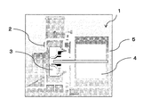
図1は、本発明の実施形態におけるポンプ装置1の外観図。図2は同ポンプ装置1の断面図である。ポンプ装置1は、ケーシング2、インペラ3、モータ4、モータケース5、で構成されており、インペラ3の回転方向を切り換える制御手段を備えている。また、ケーシングは、吸込口10と、2つの吐出管(第1吐出管11および第2吐出管12)を備えている。
FIG. 1 is an external view of a
図3は、ポンプ装置1のケーシング2とインペラ3の位置関係を示す図である。第1吐出管11および第2吐出管12は、インペラ3を径方向外側で囲むケーシング2の周壁から伸びている。インペラ3がCCW方向に回転すると、流体は、吸込口10から吸込まれ、遠心力によって水に圧力と速度が与えられて、第1吐出管11から吐出される(図4参照)。同様に、インペラ3がCW方向に回転すると、流体は第2吐出管12から吐出される。
FIG. 3 is a diagram illustrating a positional relationship between the
図6は、ケーシング2の上面図である。ケーシング2の内周壁15において、第1吐出管11および第2吐出管12に挟まれた位置に凸部20が形成されている。インペラ3の回転方向CCWおよびCWにおける凸部20の第1端部21および第2端部22は、それぞれ、吐出管の軸線方向において、第1吐出管11の第1内周面13より内側(管路内)に、第2吐出管12の第2内周面14より内側(管路内)に位置するように形成されている。また、凸部20の第1端部21及び第2端部22は、先端部分から第1吐出管11及び第2吐出管12の入口側に向かって傾斜した形状に形成している。
FIG. 6 is a top view of the
凸部20の第1端部21および第2端部22は、それぞれ、吐出管の軸線方向において、第1吐出管11の第1内周面13より内側(管路内)に、第2吐出管12の第2内周面14より内側(管路内)に位置するように形成し、凸部20の第1端部21及び第2端部22は、先端部分から第1吐出管11及び第2吐出管12の入口側に向かって傾斜した形状に形成している。これにより、インペラ3の回転による流体を第1吐出管11、または第2吐出管12に向けて案内し、効率を向上することができる。また、インペラ3の回転方向と逆方向の吐出管への流体の流れ抑制することができ、インペラ3の回転方向側の吐出管へ流体を効率よく送ることができる。
The
本構成によれば、他方の吐出管からの漏れを抑制しながら、流体を選択的に吐出させることができる。また、切換弁などの回動部が無いので、異物つまりを抑制することができる。 According to this configuration, the fluid can be selectively discharged while suppressing leakage from the other discharge pipe. Further, since there is no rotating part such as a switching valve, foreign matter clogging can be suppressed.
第1吐出管11の内径D1は、第2吐出管12の内径D2よりも大きく形成されている(本実施形態では、D1=約19mm、D2=約14mm)。第1閉塞部31を吐出管の軸線方向から見た時の閉塞面積S1は、第2閉塞部32を吐出管の軸線方向から見た時の閉塞面積S2よりも大きくなるように形成されている(本実施形態では、S1=約145mm2、S2=約114mm2)。これにより、他方からの漏れを抑制しつつ、効率良く流体を吐出することができる。
An inner diameter D1 of the
図5はケーシング2の正面図および斜視図である。第1端部21および第2端部22は、インペラ3の回転軸と略平行であるように形成されている。これにより、ケーシング2を樹脂成形する場合、凸部20をインペラ3の回転軸方向から見た場合の第1端部21および第2端部22にRを付ける事ができるため、流体に糸くずが混入する洗濯機などにおいて、異物つまりを抑制することができる。
FIG. 5 is a front view and a perspective view of the
図8は、ポンプ装置1の斜視図である。凸部20において、第1端部21および第2端部22の近傍から、ケーシング2の第1内周面13と第2内周面14とを繋ぐ第1壁面41および第2壁面42が形成されている。これにより、インペラ3がCCW方向およびCW方向に回転すると、流体が、第1開口部51および第2開口部52に効率良く案内されると共に、他方からの漏れが抑制される。
FIG. 8 is a perspective view of the
1 ポンプ装置
2 ケーシング
3 インペラ
4 モータ
5 モータケース
10 吸込口
11 第1吐出管
12 第2吐出管
13 第1内周面
14 第2内周面
15 内周壁
20 凸部
21 第1端部
22 第2端部
31 第1閉塞部
32 第2閉塞部
41 第1壁面
42 第2壁面
DESCRIPTION OF
Claims (3)
Priority Applications (1)
| Application Number | Priority Date | Filing Date | Title |
|---|---|---|---|
| JP2014186082A JP6283820B2 (en) | 2014-09-12 | 2014-09-12 | Pump device |
Applications Claiming Priority (1)
| Application Number | Priority Date | Filing Date | Title |
|---|---|---|---|
| JP2014186082A JP6283820B2 (en) | 2014-09-12 | 2014-09-12 | Pump device |
Publications (2)
| Publication Number | Publication Date |
|---|---|
| JP2016056780A JP2016056780A (en) | 2016-04-21 |
| JP6283820B2 true JP6283820B2 (en) | 2018-02-28 |
Family
ID=55758022
Family Applications (1)
| Application Number | Title | Priority Date | Filing Date |
|---|---|---|---|
| JP2014186082A Active JP6283820B2 (en) | 2014-09-12 | 2014-09-12 | Pump device |
Country Status (1)
| Country | Link |
|---|---|
| JP (1) | JP6283820B2 (en) |
Family Cites Families (4)
| Publication number | Priority date | Publication date | Assignee | Title |
|---|---|---|---|---|
| JPH01167500A (en) * | 1987-12-21 | 1989-07-03 | Seiko Epson Corp | Air blower |
| JP4527352B2 (en) * | 2002-12-16 | 2010-08-18 | アスモ株式会社 | Pump device and vehicle washer pump device |
| JP2006177329A (en) * | 2004-12-24 | 2006-07-06 | Asahi Kogyo Kk | Pump |
| JP6202665B2 (en) * | 2013-03-22 | 2017-09-27 | 株式会社タダノ | External power supply connection device for work machines |
-
2014
- 2014-09-12 JP JP2014186082A patent/JP6283820B2/en active Active
Also Published As
| Publication number | Publication date |
|---|---|
| JP2016056780A (en) | 2016-04-21 |
Similar Documents
| Publication | Publication Date | Title |
|---|---|---|
| KR101684166B1 (en) | Suction unit | |
| US9631633B2 (en) | Rotor for a centrifugal flow machine and a centrifugal flow machine | |
| JP6682483B2 (en) | Centrifugal rotating machine | |
| KR20160122707A (en) | Magnetic pump | |
| JP6351216B2 (en) | Pump blade for submersible pump and submersible pump equipped with the same | |
| CN102686886B (en) | Submersible pump | |
| JP6220837B2 (en) | Vane pump | |
| KR101373691B1 (en) | Turbulent anti-impeller and having it pump | |
| KR101832131B1 (en) | A pump for boiler | |
| JP6283820B2 (en) | Pump device | |
| WO2016157584A1 (en) | Impeller and centrifugal compressor | |
| JP4770681B2 (en) | Vertical shaft pump | |
| JP5683693B2 (en) | System used in rolling mill oil film bearings | |
| JP6488167B2 (en) | Centrifugal pump | |
| KR101687165B1 (en) | submerged pump | |
| JP2015178776A (en) | Centrifugal impeller and centrifugal pump including the same | |
| JP2015078679A (en) | Pump | |
| JP2014214714A (en) | Pump | |
| JP6236958B2 (en) | Gear pump | |
| JP2007092565A (en) | Centrifugal pump, mixed flow pump, axial flow pump | |
| JP5300508B2 (en) | Pump impeller and pump | |
| JP6168705B2 (en) | Centrifugal compressor impeller | |
| JP2018035778A5 (en) | ||
| JP2008248833A (en) | Vane pump | |
| KR200437914Y1 (en) | Impeller of exhaust water pump |
Legal Events
| Date | Code | Title | Description |
|---|---|---|---|
| RD01 | Notification of change of attorney |
Free format text: JAPANESE INTERMEDIATE CODE: A7421 Effective date: 20160520 |
|
| A621 | Written request for application examination |
Free format text: JAPANESE INTERMEDIATE CODE: A621 Effective date: 20161117 |
|
| A977 | Report on retrieval |
Free format text: JAPANESE INTERMEDIATE CODE: A971007 Effective date: 20170821 |
|
| A131 | Notification of reasons for refusal |
Free format text: JAPANESE INTERMEDIATE CODE: A131 Effective date: 20170829 |
|
| A521 | Written amendment |
Free format text: JAPANESE INTERMEDIATE CODE: A523 Effective date: 20171024 |
|
| TRDD | Decision of grant or rejection written | ||
| A01 | Written decision to grant a patent or to grant a registration (utility model) |
Free format text: JAPANESE INTERMEDIATE CODE: A01 Effective date: 20171219 |
|
| A61 | First payment of annual fees (during grant procedure) |
Free format text: JAPANESE INTERMEDIATE CODE: A61 Effective date: 20180101 |
|
| R151 | Written notification of patent or utility model registration |
Ref document number: 6283820 Country of ref document: JP Free format text: JAPANESE INTERMEDIATE CODE: R151 |