JP6283213B2 - Rotary cutting tool for grooving - Google Patents
Rotary cutting tool for grooving Download PDFInfo
- Publication number
- JP6283213B2 JP6283213B2 JP2013261149A JP2013261149A JP6283213B2 JP 6283213 B2 JP6283213 B2 JP 6283213B2 JP 2013261149 A JP2013261149 A JP 2013261149A JP 2013261149 A JP2013261149 A JP 2013261149A JP 6283213 B2 JP6283213 B2 JP 6283213B2
- Authority
- JP
- Japan
- Prior art keywords
- cutting tool
- rotary cutting
- cutter
- vibration
- grooving
- Prior art date
- Legal status (The legal status is an assumption and is not a legal conclusion. Google has not performed a legal analysis and makes no representation as to the accuracy of the status listed.)
- Active
Links
- 230000007246 mechanism Effects 0.000 claims description 91
- 238000002955 isolation Methods 0.000 claims description 35
- 239000000463 material Substances 0.000 claims description 14
- 230000002093 peripheral effect Effects 0.000 claims description 14
- XEEYBQQBJWHFJM-UHFFFAOYSA-N Iron Chemical compound [Fe] XEEYBQQBJWHFJM-UHFFFAOYSA-N 0.000 claims description 8
- 238000003754 machining Methods 0.000 claims description 5
- 229910052742 iron Inorganic materials 0.000 claims description 4
- 229910001080 W alloy Inorganic materials 0.000 claims description 3
- 238000013016 damping Methods 0.000 description 9
- 230000000694 effects Effects 0.000 description 9
- 230000004044 response Effects 0.000 description 9
- 238000010586 diagram Methods 0.000 description 4
- 238000003801 milling Methods 0.000 description 4
- 230000002238 attenuated effect Effects 0.000 description 2
- 230000002452 interceptive effect Effects 0.000 description 2
- 238000000034 method Methods 0.000 description 2
- 239000006096 absorbing agent Substances 0.000 description 1
- 230000009471 action Effects 0.000 description 1
- 239000000853 adhesive Substances 0.000 description 1
- 230000001070 adhesive effect Effects 0.000 description 1
- 229910045601 alloy Inorganic materials 0.000 description 1
- 239000000956 alloy Substances 0.000 description 1
- 238000005452 bending Methods 0.000 description 1
- 239000010730 cutting oil Substances 0.000 description 1
- 230000006866 deterioration Effects 0.000 description 1
- JEIPFZHSYJVQDO-UHFFFAOYSA-N iron(III) oxide Inorganic materials O=[Fe]O[Fe]=O JEIPFZHSYJVQDO-UHFFFAOYSA-N 0.000 description 1
- 239000007788 liquid Substances 0.000 description 1
- 229910052751 metal Inorganic materials 0.000 description 1
- 239000002184 metal Substances 0.000 description 1
- 238000012986 modification Methods 0.000 description 1
- 230000004048 modification Effects 0.000 description 1
- 239000003921 oil Substances 0.000 description 1
- 230000002265 prevention Effects 0.000 description 1
- 230000008569 process Effects 0.000 description 1
- 230000035939 shock Effects 0.000 description 1
- 230000001629 suppression Effects 0.000 description 1
- WFKWXMTUELFFGS-UHFFFAOYSA-N tungsten Chemical compound [W] WFKWXMTUELFFGS-UHFFFAOYSA-N 0.000 description 1
- 229910052721 tungsten Inorganic materials 0.000 description 1
- 239000010937 tungsten Substances 0.000 description 1
Images


Classifications
-
- B—PERFORMING OPERATIONS; TRANSPORTING
- B23—MACHINE TOOLS; METAL-WORKING NOT OTHERWISE PROVIDED FOR
- B23C—MILLING
- B23C5/00—Milling-cutters
- B23C5/003—Milling-cutters with vibration suppressing means
-
- B—PERFORMING OPERATIONS; TRANSPORTING
- B23—MACHINE TOOLS; METAL-WORKING NOT OTHERWISE PROVIDED FOR
- B23C—MILLING
- B23C5/00—Milling-cutters
- B23C5/006—Details of the milling cutter body
-
- B—PERFORMING OPERATIONS; TRANSPORTING
- B23—MACHINE TOOLS; METAL-WORKING NOT OTHERWISE PROVIDED FOR
- B23C—MILLING
- B23C5/00—Milling-cutters
- B23C5/02—Milling-cutters characterised by the shape of the cutter
- B23C5/08—Disc-type cutters
-
- B—PERFORMING OPERATIONS; TRANSPORTING
- B23—MACHINE TOOLS; METAL-WORKING NOT OTHERWISE PROVIDED FOR
- B23C—MILLING
- B23C2250/00—Compensating adverse effects during milling
- B23C2250/16—Damping vibrations
-
- B—PERFORMING OPERATIONS; TRANSPORTING
- B23—MACHINE TOOLS; METAL-WORKING NOT OTHERWISE PROVIDED FOR
- B23C—MILLING
- B23C2260/00—Details of constructional elements
- B23C2260/04—Adjustable elements
-
- Y—GENERAL TAGGING OF NEW TECHNOLOGICAL DEVELOPMENTS; GENERAL TAGGING OF CROSS-SECTIONAL TECHNOLOGIES SPANNING OVER SEVERAL SECTIONS OF THE IPC; TECHNICAL SUBJECTS COVERED BY FORMER USPC CROSS-REFERENCE ART COLLECTIONS [XRACs] AND DIGESTS
- Y10—TECHNICAL SUBJECTS COVERED BY FORMER USPC
- Y10T—TECHNICAL SUBJECTS COVERED BY FORMER US CLASSIFICATION
- Y10T407/00—Cutters, for shaping
- Y10T407/19—Rotary cutting tool
- Y10T407/1906—Rotary cutting tool including holder [i.e., head] having seat for inserted tool
- Y10T407/1942—Peripherally spaced tools
Description
本発明は溝加工用回転式切削工具に係り、特に、防振機構を備えたものに好適な溝加工用回転式切削工具に関する。 The present invention relates to a rotary cutting tool for grooving, and more particularly to a rotary cutting tool for grooving that is suitable for a tool having a vibration isolation mechanism.
ディスクカッタと呼ばれるディスク形状の工具で溝を加工することが、一般的に行われている。 It is a common practice to process a groove with a disk-shaped tool called a disk cutter.
図1は、この例を示すものであり、工具径Dのディスクカッタ1の外周部分には、切れ刃となるカートリッジ2が備えられ、ディスクカッタ1が円周方向に回転することで、被削材3に所望の溝4が加工される。このとき、ディスクカッタ1の工具径Dが、より大きなものほど加工中に発生する工具の振動が増大し、工具刃先の破損等が発生し加工精度が低下する問題がある。
FIG. 1 shows an example of this. A
図2及び図3は、加工中におけるディスクカッタ1の振動モードの一例を示した図である。該図は、有限要素法によって工具径Dが1200mmのディスクカッタ1のモード解析を行ったものである。ディスクカッタ1は、主軸5に固定された状態である。図2及び図3に示す如く、ディスクカッタ1の振動モードは、ディスクカッタ1の外周部がz軸方向に波打つ形状になることが分かる。例えば、z方向の振動振幅が最大となる267Hzの周波数(図2)では、ディスクカッタ1の外周に、節が4ヶ所形成される振動モードである。また、374Hzの周波数(図3)では、ディスクカッタ1の外周に、節が6ヶ所形成される振動モードである。
2 and 3 are diagrams showing an example of a vibration mode of the
このように、ディスクカッタ1の支配的な振動は、ディスクカッタ1の外周部分がz方向に波打つように変位するモードであることがわかる。
Thus, it can be seen that the dominant vibration of the
このようなディスク形状の工具で被削材を加工する先行技術文献として、特許文献1及び2に記載されたものがある。
As prior art documents for machining a workpiece with such a disk-shaped tool, there are those described in
即ち、特許文献1には、回転切削加工用のフライス工具が回転軸を有すると共に、工具本体の一端に配置された個々の転削インサートを受ける複数のインサート座を有する工具本体を備え、フライス工具は、工具本体の内側に配置され、工具に発生する振動を抑制する複数の減衰要素を備え、減衰要素が回転軸に平行で、回転軸から半径方向に離れると共に、工具本体の一端に隣接して配置されることが記載されている。
That is, in
また、特許文献2には、円盤状の本体に切れ刃を取り付けた回転切削工具において、前記円盤状の本体の端面側に円環状の溝を形成し、当該溝に、粘弾性体を介してリング状の錘を設け、工具本体の回転軸方向に前記錘が前記本体と相対的に移動可能に構成することが記載されている。
Moreover, in
上述した特許文献1には、工具本体に備えられた複数の減衰要素で、工具に発生する振動を抑制するフライス工具が記載されている。しかしながら、特許文献1では、減衰要素の構造詳細が記載されておらず、振動抑制対象とする振動モードが、特許文献1のフライス工具と異なる場合、振動方向が異なることが考えられるため、振動が抑制できない可能性があり、そのままでは適用できない。
また、特許文献2には、工具直径方向及び工具回転軸方向それぞれに切削力が生じた際の振動モードにおける防振機構及び工具が記載されている。しかしながら、特許文献2の防振機構は、工具の振動モードが工具刃先1ヶ所のみで変位する場合と、回転軸に対して撓み方向に振動する場合のみを対象としているもので、ディスク形状の工具において、工具の振動モードが刃先に節が複数個発生する形態を対象としたものには適用できないという問題があった。
本発明は上述の点に鑑みなされたもので、その目的とするところは、工具の振動モードが刃先に節が複数個発生する形態を対象としたものであっても、工具の振動を抑制することができる溝加工用回転式切削工具を提供することにある。 The present invention has been made in view of the above points, and the object thereof is to suppress the vibration of the tool even when the vibration mode of the tool is directed to a form in which a plurality of nodes are generated at the cutting edge. It is an object of the present invention to provide a rotary cutting tool for grooving.
本発明の溝加工用回転式切削工具は、上記目的を達成するために、ディスク状のカッタの外周部分に、切り刃となるカートリッジを円周方向に所定の間隔をもって複数個備え、前記ディスク状のカッタが円周方向に回転することで、前記カートリッジで被削材に所定の溝を加工する溝加工用回転式切削工具であって、前記ディスク状のカッタの端面上に、円周方向に複数内蔵された防振機構を備え、前記防振機構は、錘と、該錘の両端面に設置され前記カッタの振動を減衰するリング状の粘弾性体と、該粘弾性体の片側の端面に設置され該粘弾性体の圧力を調整するシムと、該シムと粘弾性体及び錘を前記カッタボディの内部に内蔵するためのカバーとから成ることを特徴とする。 In order to achieve the above-mentioned object, the rotary cutting tool for grooving of the present invention comprises a plurality of cartridges serving as cutting blades at predetermined intervals in the circumferential direction on the outer peripheral portion of a disk-shaped cutter. A rotary cutting tool for machining a predetermined groove on the work material by the cartridge by rotating the cutter in a circumferential direction, wherein the cutter is rotated circumferentially on an end face of the disc-shaped cutter. A plurality of built-in anti-vibration mechanisms , wherein the anti-vibration mechanism includes a weight, a ring-shaped viscoelastic body that is installed on both end faces of the weight to attenuate the vibration of the cutter, and an end face on one side of the viscoelastic body And a cover for adjusting the pressure of the viscoelastic body and a cover for incorporating the shim, the viscoelastic body, and the weight inside the cutter body .
本発明によれば、工具の振動モードが刃先に節が複数個発生する形態を対象としたものであっても、工具の振動を抑制するディスク形状の溝加工用回転式切削工具を得ることができる。 According to the present invention, it is possible to obtain a disc-shaped rotary cutting tool for grooving that suppresses vibration of a tool even when the vibration mode of the tool is intended for a form in which a plurality of nodes are generated at the cutting edge. it can.
以下、図示した実施例に基づいて本発明の溝加工用回転式切削工具を説明する。なお、各実施例において、同一構成部品には同符号を使用する。 Hereinafter, the rotary cutting tool for grooving of the present invention will be described based on the illustrated embodiment. In addition, in each Example, the same code | symbol is used for the same component.
図4に、本発明の溝加工用回転式切削工具の実施例1である防振機構付きのディスクカッタ9を示し、防振機構6を備えた溝加工用回転式切削工具の例である。ここでは、工具径Dが1200mmのディスクカッタ9を用いて説明する。
FIG. 4 shows a
該図に示す如く、本実施例の防振機構付きのディスクカッタ9は、ディスク状のカッタボディ8と、このディスク状のカッタボディ8の外周に、円周方向に所定の間隔をもって複数個設けられた切れ刃となるカートリッジ2と、このカートリッジ2に取り付けられるインサート7と、カッタボディ8と一体になって該カッタボディ8を回転させる主軸5と、カッタボディ8の外周側に内蔵される防振機構6とで概略構成されている。防振機構6は、カッタボディ8の端面上に、複数個内蔵されることが望ましい。
As shown in the figure, a
ところで、従来のディスクカッタ1の振動モードは、図2及び図3で説明したように、全ての刃が同方向に振動しておらず、外周部がz軸方向に波打つように振動する。そのため、防振機構6は、各刃に合った位相で振動を抑制する必要があり、例えば、図4の本実施例のように、ディスカッタ9の刃数と同じ個数が、ディスカッタ9の端面円周状に等しいピッチで設置することにより、効果的に振動を抑制することができる。
By the way, the vibration mode of the
図5に、本実施例の防振機構付きのディスクカッタ9に採用される防振機構6の構成の一例を示す。
FIG. 5 shows an example of the configuration of the
該図に示す如く、本実施例に採用される防振機構6は、錘11と、この錘11の両端面に設置されディスクカッタ9の振動を減衰するリング状の粘弾性体10A、10Bと、この粘弾性体10Aの片側の端面に設置され、粘弾性体10Aの圧力を調整する調整用シム12と、該調整用シム12と粘弾性体10A、10B及び錘11をカッタボディ8の内部に内蔵するためのカバー13と、リング状粘弾性体15とから構成されている。そして、これら錘11、粘弾性体10A、10B、リング状粘弾性体15、調整用シム12及びカバー13は、図4に示すカッタボディ8の外周側に形成されている防振機構取付け穴16に内蔵される。
As shown in the figure, the
なお、防振機構6は、被削材3との干渉を避けるために、ディスカッタ9の内部に取り付ける必要がある。また、切りくずの噛みこみや切削油が防振機構6にかかることによる粘弾性体10A、10Bの劣化及び防振機能低下を防ぐために、カバー13によって密閉しても良い。
The
また、カバー13は、高速回転するカッタボディ8に取り付けられるため、加工中に脱落しないように、例えば、ネジ14によって強固に固定される。このネジ14は、錘11の振動でカバー13が外れないよう、小ネジ14を6個均等に固定しても良いし、加工中にネジ14が被削材3に干渉しないようにするため、カバー13には深座ぐりを施し、ネジ14は皿小ネジを用いることが望ましい。また、ネジ14の脱落を防ぐために、ネジ緩み止め接着剤を塗布しても良い。
Further, since the
本実施例の防振機構付きのディスクカッタ9に採用される防振機構6の断面を、図6に示す。
FIG. 6 shows a cross section of the
該図に示す如く、防振機構6は、錘11が粘弾性体10A、10Bによってz軸上下方向から挟みこまれている構造になっており、カッタボディ8が振動すると錘11は、z軸方向に逆位相に振動する。この作用によって、ディスクカッタ9の振動モードにおける振動が減衰する。
As shown in the figure, the
また、粘弾性体10Aとカバー13の間には、調整用シム12が挟み込まれており、調整用シム12は、カバー13がカッタボディ8に固定される際に、粘弾性体10Aを変形させて圧縮する役割がある。
Further, an
これにより、錘11を挟み込む粘弾性体10A、10Bに適切な圧力が加わる。例えば、錘11がz軸下方向に移動すると、下部の粘弾性体10Bは錘11に圧縮されて縮むが、上部の粘弾性体10Aは圧力が解放されるため伸長する。従って、双方の粘弾性体10A、10Bは、調整用シム12によって予め圧力が加わっており、錘11と粘弾性体10A、10Bの接触が分離しない。
Accordingly, an appropriate pressure is applied to the
また、調整用シム12の厚さ若しくは枚数を変えることによって、振動抑制対象の周波数に適応した粘弾性体10A、10Bの減衰特性を調整することが可能となる。
In addition, by changing the thickness or number of the adjustment shims 12, it is possible to adjust the damping characteristics of the
図4に示す防振機構付きのディスクカッタ9は、防振機構6が回転軸を中心にカッタボディ8の外周上に備えられているため、ディスクカッタ9が高速回転すると、遠心力の影響を無視できなくなる。
The
この遠心力の影響で、防振機構6の構成部品である錘11は、錘11の側面がカッタボディ8に押しつけられてカッタボディ8と干渉し、防振機構6がディスクカッタ9を減衰しないことが考えられる。
Due to the centrifugal force, the
この干渉を回避するために、錘11の側面に溝を施し、この溝にOリングをはじめとするリング状粘弾性体15を取り付けても良い。このとき、錘11がリング状粘弾性体15を介して均等にカッタボディ8に接触するためには、錘11の少なくとも2ヶ所に、リング状粘弾性体15を取り付けることが望ましい。
In order to avoid this interference, a groove may be formed on the side surface of the
図7は、本実施例で説明した防振機構6を備えるディスクカッタ9のz軸方向の応答振幅を示した特性図である。該図は、ディスクカッタ9の直径が1200mmで、防振機構6の錘11の質量が100gの応答振幅を計算した結果である。
FIG. 7 is a characteristic diagram showing the response amplitude in the z-axis direction of the
該図に示す如く、防振機構6を備えていない従来のディスクカッタ(点線A)では、固有振動数267Hzにおいて、応答振幅の最大値は3.83×10⁻⁶m/Nである。
As shown in the figure, in the conventional disc cutter (dotted line A) not provided with the
これに対して、本実施例の防振機構6を備えるディスクカッタ(実線B)は、応答振幅の最大値が5.21×10⁻⁷m/Nとなり、動剛性を約86%向上することができ、加工精度を向上することが可能となる。
On the other hand, the disc cutter (solid line B) provided with the
また、減衰効果をさらに向上したい場合は、錘11の質量を増加すれば良い。例えば、寸法が直径45mm、厚さ20mmの錘11の場合、材質を鉄系材料であるSS400とすると約260gとなる。これをより減衰効果を上げるために、鉄系材料の約2倍の密度を有するタングステン合金を用いると、質量は約590gとなり、更に減衰効果が向上する。
In order to further improve the damping effect, the mass of the
このような本実施例の構成とすることにより、ディスク形状のディスクカッタ9が複数の節が生じる振動モードであっても、効果的に振動を抑制することができる。
By adopting such a configuration of the present embodiment, even when the disk-shaped
図8に、本発明の実施例2である防振機構付きのディスクカッタ9に採用される防振機構6Aの断面を示す。
FIG. 8 shows a cross section of an anti-vibration mechanism 6A employed in a
本発明での防振機構は、実施例1と全て同じ構成である必要はない。図8に示す本実施例では、実施例1で説明した防振機構6に改良を加え、ロッド20とリニアブッシュ21を用いて防振機構6Aを構成した例である。
The anti-vibration mechanism in the present invention does not necessarily have the same configuration as that of the first embodiment. The present embodiment shown in FIG. 8 is an example in which the vibration-
図8に示す如く、本実施例では、ロッド20とリニアブッシュ21が、錘11の中心に形成された貫通孔を通って設置されている。また、錘11は、粘弾性体10A、10Bによりz軸上下方向から挟み込まれており、粘弾性体10Aとカバー13の間には調整用シム12が挟み込まれている。また、ロッド21は、カッタボディ8とカバー13に固定されている。他の構成は、実施例1と同様である。
As shown in FIG. 8, in this embodiment, the
このような本実施例の構成とすることにより、その効果は、実施例1と同様であることは勿論、ロッド20及びリニアブッシュ21によって、遠心力による錘11とカッタボディ8の干渉を防ぐことができ、錘11をz方向にスムーズに移動することができる。
By adopting such a configuration of the present embodiment, the effect is the same as that of the first embodiment, and the
なお、ロッド20と錘11が滑らかにz軸方向に移動できる場合は、リニアブッシュ21は無くても良い。
If the
図9に、本発明の実施例3である防振機構付きのディスクカッタ9に採用される防振機構6Bの断面を示す。
FIG. 9 shows a cross section of an
該図に示す本実施例では、ボルト25の締め付けによって、減衰の調整を行う防振機構6Bである。
In the present embodiment shown in the figure, the
図9に示す如く、本実施例の防振機構6Bは、ボルト25、粘弾性体10A、10B、錘11、カバー13、ネジ14より構成されており、これらはカッタボディ8に内蔵されている。錘11及び粘弾性体10A、10Bには、中心にボルト25の直径よりわずかに大きい貫通穴が形成されており、ボルト25はその貫通穴を通って、カッタボディ8に締め付けられる。ボルト25の締付調整によって、粘弾性体10A、10Bには予め圧力が加わり、ディスクカッタ9の振動を減衰する役割を果たす。錘11上部の粘弾性体10Aは、ボルト25の柄と錘11に挟み込まれているが、ボルト25の柄との接触面積を広げ、ボルト25の締め付けによる圧力を粘弾性体10A、10Bに、より均一に与えたい場合は、ボルト25の柄と錘11上部の粘弾性体10Aの間に、ワッシャやシムリング等挟み込んでも良い。
As shown in FIG. 9, the
また、ボルト25が通る錘11の中心にある貫通穴は、錘11がボルト25と干渉せずにz軸方向に滑らかに移動できるため、ボルト25の直径より少し大きめの穴径を有することが望ましいが、遠心力の影響下でも摩擦抵抗を極力減らして滑らかに移動させたいときは、錘11とボルト25の隙間にリニアブッシュを噛ませても良い。
Further, the through hole at the center of the
このような本実施例の構成であっても、その効果は、実施例2と同様である。 Even in the configuration of this embodiment, the effect is the same as that of the second embodiment.
なお、本実施例では、粘弾性体10A、10Bと錘11を適切な圧力で締め付けることができれば良いので、特に、ボルト25に特定するわけでなく、その他の各種ネジ等でも良いことは言うまでもない。
In the present embodiment, the
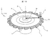
次に、実施例4として、ディスクカッタ9において、実施例1で説明した防振機構6を取り付ける位置の例について、図10乃至図12を用いて説明する。図10乃至図12は、それぞれ防振機構6の取付け位置が変化した時のディスクカッタ9の例である。
Next, as a fourth embodiment, an example of a position where the
図10乃至図12に示す如く、防振機構6の取り付ける位置を、ディスクカッタ9の回転軸から防振機構6までの距離30、31、32で表しており、カッタボディ8の端面上において、ディスクカッタ9の外周円方向に備えられている。防振機構6は、ディスクカッタ9の振動において、最も振幅が大きい部位に装着すると効果が高い。
As shown in FIGS. 10 to 12, the mounting position of the
本実施例のようなディスクカッタ9において、最も振幅が大きくなる部分は、図2及び図3を用いて説明したように、ディスクカッタ9の刃先先端部になる。
In the
そこで、ディスクカッタ9の刃先先端部に近い場所に防振機構6を取り付けたときの例が、図10である。該図に示す如く、防振機構6は、ディスクカッタ9の刃先部分に埋め込まれており、切れ刃に最も近い部分になるため、切削力に十分に耐え得る剛性が確保できれば取り付けが可能である。
FIG. 10 shows an example in which the
ただし、取り付ける領域も限られているため、防振機構6の寸法が限られる。寸法が限られることによって、錘11の寸法が制限されるが、錘11の材質を鉄系材料の約2倍の密度を有するタングステン合金等を用いれば、十分に錘の重さを確保できる。例えば、直径1200mmのディスクカッタ9の場合、刃先部分に錘11を取り付ける場合における位置は、回転軸より530mm離れた位置で、円柱状の錘11の寸法は直径50mm、厚さ20mm、材質がタングステン合金、質量約730gとなり、ディスクカッタ9の振動を抑制するためには十分な質量を確保することができる。
However, since the attachment area is also limited, the dimensions of the
次に、ディスクカッタ9の刃先部分から回転軸方向に向かってカッタボディ8の内側に防振機構6を取り付けた例が、図11である。該図に示す如く、防振機構6の位置が切れ刃の根元付近になり、ディスクカッタ9が振動する際の振幅はやや小さくなる部分であるが、切れ刃から離れるため、切削力の影響や防振機構6の寸法の制限が緩和される。直径1200mmのディスクカッタ9の場合、防振機構6を取り付ける位置は、例えば、中心軸より約450mmとなる。
Next, FIG. 11 shows an example in which the
また、ディスクカッタ9の刃先部分から回転軸方向に向かってカッタボディ8の更に内側に防振機構6を取り付けた例が、図12である。この場合、直径1200mmのディスクカッタ9において、防振機構6を取り付ける位置は、約340mmとなる。最も振動が大きい刃先部分から離れるため、防振機構6の効果は図10及び図11の構成に比較して低くなるが、防振機構6を備えていないものに比べれば、それなりの防振効果はある。
FIG. 12 shows an example in which the
図10乃至図12に示したそれぞれの防振機構6の取り付け位置における応答振幅を、図13に示す。このときの錘11の質量は100gである。図13は、横軸に防振機構6を取り付ける位置で回転軸から防振機構6までの距離(mm)を示し、縦軸に最大応答振幅(m/N)を示した図である。該図から最大応答振幅の値が低くなるほど、防振効果が高いといえる。
FIG. 13 shows the response amplitude at the mounting position of each
このように、回転軸から防振機構6までの距離が長い、つまり刃先に近い位置に防振機構6を取り付けるときが、最も防振効果が得られることが分かる。
Thus, it can be seen that the most anti-vibration effect can be obtained when the
また、本発明では、振動を減衰する構成要素に粘弾性体10A、10Bを用いているが、特にこれに限定する必要性はなく、例えば、皿バネなどの各種バネ、ダッシュポット、ショックアブソーバ、その他ダンパなどでも良い。
Further, in the present invention, the
また、上述した本発明の防振機構6、6A、6Bは、それらの一部又は全部を、円柱状の形状ではなく、直方体をはじめとする角柱形状など、ディスクカッタ9の内部に内蔵できる形状であればよい。また、防振機構6、6A、6Bの内部において、金属部品の錆止めや摩擦軽減のために、油等の液体を満たしても良い。また、防振機構6、6A、6Bの数は、ディスクカッタ9の刃数と同数である必要はなく、刃数より多くても良く、少なくても良い。
Further, the above-described
更に、本発明は、ディスクカッタだけでなくフライス工具など、ディスク形状の工具を含んでも良い。 Furthermore, the present invention may include not only a disc cutter but also a disc-shaped tool such as a milling tool.
なお、本発明は上記した実施例に限定されるものではなく、様々な変形例が含まれる。例えば、上記した実施例は本発明を分かりやすく説明するために詳細に説明したものであり、必ずしも説明した全ての構成を備えるものに限定されるものではない。また、ある実施例の構成の一部を他の実施例の構成に置き換えることが可能であり、また、ある実施例の構成に他の実施例の構成を加えることも可能である。また、各実施例の構成の一部について、他の構成の追加・削除・置換をすることが可能である。 In addition, this invention is not limited to an above-described Example, Various modifications are included. For example, the above-described embodiments have been described in detail for easy understanding of the present invention, and are not necessarily limited to those having all the configurations described. Further, a part of the configuration of one embodiment can be replaced with the configuration of another embodiment, and the configuration of another embodiment can be added to the configuration of one embodiment. Further, it is possible to add, delete, and replace other configurations for a part of the configuration of each embodiment.
1、9…ディスクカッタ、2…カートリッジ、3…被削材、4…溝、5…主軸、6、6A、6B…防振機構、7…インサート、8…カッタボディ、9…防振機構付ディスクカッタ、10A、10B…粘弾性体、11…錘、12…調整用シム、13…カバー、14…ネジ、15…リング状粘弾性体、16…防振機構取付け穴、20…ロッド、21…リニアブッシュ、25…ボルト、30、31、32…ディスクカッタの回転軸から防振機構までの距離。
DESCRIPTION OF
Claims (10)
前記ディスク状のカッタの端面上に、円周方向に複数内蔵された防振機構を備え、
前記防振機構は、錘と、該錘の両端面に設置され前記カッタの振動を減衰するリング状の粘弾性体と、該粘弾性体の片側の端面に設置され該粘弾性体の圧力を調整するシムと、該シムと粘弾性体及び錘をカッタボディの内部に内蔵するためのカバーとから成ることを特徴とする溝加工用回転式切削工具。 A plurality of cartridges serving as cutting blades are provided at predetermined intervals in the circumferential direction on the outer peripheral portion of the disk-shaped cutter, and the disk-shaped cutter rotates in the circumferential direction so that a predetermined work material is applied to the work material by the cartridge. A rotary cutting tool for machining a groove of
On the end face of the disk-shaped cutter, provided with a plurality of vibration isolation mechanisms built in the circumferential direction ,
The anti-vibration mechanism includes a weight, a ring-shaped viscoelastic body that is installed on both end surfaces of the weight and attenuates vibrations of the cutter, and a pressure on the viscoelastic body that is installed on one end surface of the viscoelastic body. A rotary cutting tool for grooving, comprising: a shim to be adjusted; and a cover for incorporating the shim, the viscoelastic body, and the weight in the cutter body .
前記防振機構は、前記錘の中心に貫通穴が形成され、該貫通穴を介して前記カバーと前記カッタボディに固定されたロッド及びリニアブッシュを備え、該ロッド及びリニアブッシュによって、遠心力による前記錘と前記カッタボディの干渉を防ぎ、かつ、前記錘が前記カッタボディを防振する方向に動くことを特徴とする溝加工用回転式切削工具。 In the rotary cutting tool for grooving according to claim 1 ,
The vibration isolating mechanism has a through hole formed at the center of the weight, and includes a rod and a linear bush fixed to the cover and the cutter body through the through hole. By the rod and the linear bush, a centrifugal force is applied. A rotary cutting tool for grooving, characterized in that interference between the weight and the cutter body is prevented and the weight moves in a direction to isolate the cutter body.
前記防振機構は、前記錘及び粘弾性体の中心に貫通穴が形成され、該貫通穴を介してボルト又はネジが固定され、該ボルト又はネジによる締付で前記粘弾性体の圧力が調整されることを特徴とする溝加工用回転式切削工具。 In the rotary cutting tool for grooving according to claim 1 ,
The vibration isolation mechanism has a through hole formed at the center of the weight and the viscoelastic body, a bolt or a screw is fixed through the through hole, and the pressure of the viscoelastic body is adjusted by tightening with the bolt or the screw. A rotary cutting tool for grooving.
前記ディスク状のカッタは、ディスク状のカッタボディと、該カッタボディの外周に、円周方向に所定の間隔をもって複数個設けられたカートリッジと、該カートリッジに取り付けられるインサートと、前記カッタボディと一体になって該カッタボディを回転させる主軸とから成り、
前記防振機構は、前記カートリッジと隣接する前記カッタボディの外周側或いはこの外周側より前記主軸側の前記カッタボディの内周側に内蔵されていることを特徴とする溝加工用回転式切削工具。 In the rotary cutting tool for grooving according to any one of claims 1 to 3 ,
The disc-shaped cutter includes a disc-shaped cutter body, a plurality of cartridges provided on the outer periphery of the cutter body at predetermined intervals in the circumferential direction, an insert attached to the cartridge, and the cutter body. And consists of a main shaft that rotates the cutter body,
The anti-vibration mechanism is incorporated in the outer peripheral side of the cutter body adjacent to the cartridge or on the inner peripheral side of the cutter body on the spindle side from the outer peripheral side, and the rotary cutting tool for grooving .
前記ディスク状のカッタは、ディスク状のカッタボディと、該カッタボディの外周に、円周方向に所定の間隔をもって複数個設けられたカートリッジと、該カートリッジに取り付けられるインサートと、前記カッタボディと一体になって該カッタボディを回転させる主軸とから成り、
前記防振機構は、前記カートリッジに埋め込まれていることを特徴とする溝加工用回転式切削工具。 In the rotary cutting tool for grooving according to any one of claims 1 to 3 ,
The disc-shaped cutter includes a disc-shaped cutter body, a plurality of cartridges provided on the outer periphery of the cutter body at predetermined intervals in the circumferential direction, an insert attached to the cartridge, and the cutter body. And consists of a main shaft that rotates the cutter body,
The rotary cutting tool for grooving , wherein the vibration isolation mechanism is embedded in the cartridge .
前記防振機構は、前記カートリッジと隣接する前記カッタボディの外周側或いはこの外周側より前記主軸側の前記カッタボディの内周側に形成された防振機構取付穴に内蔵されていることを特徴とする溝加工用回転式切削工具。 In the rotary cutting tool for grooving according to claim 4 ,
The anti-vibration mechanism is incorporated in an anti-vibration mechanism mounting hole formed on the outer peripheral side of the cutter body adjacent to the cartridge or on the inner peripheral side of the cutter body on the spindle side from the outer peripheral side. A rotary cutting tool for grooving.
前記防振機構は、前記カートリッジに形成された防振機構取付穴に内蔵されていることを特徴とする溝加工用回転式切削工具。 In the rotary cutting tool for grooving according to claim 5 ,
The anti-vibration mechanism is incorporated in an anti-vibration mechanism mounting hole formed in the cartridge .
前記防振機構は、前記カバーを介して前記カッタボディにネジで固定されていることを特徴とする溝加工用回転式切削工具。 In the rotary cutting tool for groove processing according to claim 6 or 7 ,
The anti-vibration mechanism is fixed to the cutter body with screws through the cover, and is a rotary cutting tool for grooving.
前記錘の側面に溝が施され、かつ、該溝にリング状粘弾性体が設置されていることを特徴とする溝加工用回転式切削工具。 In the rotary cutting tool for grooving according to any one of claims 6 to 8 ,
A rotary cutting tool for groove processing, characterized in that a groove is formed on a side surface of the weight, and a ring-like viscoelastic body is installed in the groove.
前記錘は、鉄系材料或いはタングステン合金を用いることを特徴とする溝加工用回転式切削工具。 In the rotary cutting tool for groove processing according to any one of claims 1 to 9 ,
A rotary cutting tool for grooving, wherein the weight uses an iron-based material or a tungsten alloy.
Priority Applications (2)
| Application Number | Priority Date | Filing Date | Title |
|---|---|---|---|
| JP2013261149A JP6283213B2 (en) | 2013-12-18 | 2013-12-18 | Rotary cutting tool for grooving |
| US14/574,835 US9919365B2 (en) | 2013-12-18 | 2014-12-18 | Side milling cutter for slot cutting |
Applications Claiming Priority (1)
| Application Number | Priority Date | Filing Date | Title |
|---|---|---|---|
| JP2013261149A JP6283213B2 (en) | 2013-12-18 | 2013-12-18 | Rotary cutting tool for grooving |
Publications (3)
| Publication Number | Publication Date |
|---|---|
| JP2015116635A JP2015116635A (en) | 2015-06-25 |
| JP2015116635A5 JP2015116635A5 (en) | 2016-07-07 |
| JP6283213B2 true JP6283213B2 (en) | 2018-02-21 |
Family
ID=53367271
Family Applications (1)
| Application Number | Title | Priority Date | Filing Date |
|---|---|---|---|
| JP2013261149A Active JP6283213B2 (en) | 2013-12-18 | 2013-12-18 | Rotary cutting tool for grooving |
Country Status (2)
| Country | Link |
|---|---|
| US (1) | US9919365B2 (en) |
| JP (1) | JP6283213B2 (en) |
Families Citing this family (7)
| Publication number | Priority date | Publication date | Assignee | Title |
|---|---|---|---|---|
| CN202356732U (en) * | 2011-12-11 | 2012-08-01 | 富泰华精密电子(郑州)有限公司 | Slotting cutter |
| RU2629573C2 (en) * | 2016-02-04 | 2017-08-30 | Иосиф Исаакович Фейман | Disc cutter for cutting steel pipes |
| EP3222376B1 (en) * | 2016-03-24 | 2019-01-23 | Seco Tools AB | Grooving blade, grooving tool and method of grooving a metallic workpiece |
| CN108453906B (en) * | 2018-03-29 | 2019-03-26 | 中钢集团新型材料(浙江)有限公司 | A kind of graphite material fracture toughness test grooving tool, equipment and grooving method |
| JP7241375B2 (en) * | 2020-08-18 | 2023-03-17 | 住友電工ハードメタル株式会社 | Cutting tools and machining equipment |
| CZ2020628A3 (en) * | 2020-11-23 | 2021-09-29 | Hofmeister S.R.O. | Cutter body for machining solid materials |
| EP4360786A1 (en) * | 2022-10-25 | 2024-05-01 | Palbit S.A. | Multi-slot rotary cutting tool |
Family Cites Families (11)
| Publication number | Priority date | Publication date | Assignee | Title |
|---|---|---|---|---|
| US3690414A (en) * | 1970-11-04 | 1972-09-12 | Cincinnati Milacron Inc | Vibration absorber for a supported member |
| JPS552523A (en) | 1978-06-19 | 1980-01-10 | Toyo Seikan Kaisha Ltd | Apparatus for automatically feeding stacking boards |
| JPS552523U (en) * | 1978-06-20 | 1980-01-09 | ||
| NO172677C (en) * | 1991-02-21 | 1993-08-25 | Teeness As | Device for damping vibrations, for example self-generated oscillations in drill rods and the like |
| IL127827A (en) * | 1998-12-29 | 2001-08-08 | Iscar Ltd | Slotting cutter |
| JP2001328022A (en) * | 2000-05-24 | 2001-11-27 | Mitsubishi Materials Corp | Vibration damping tool |
| JP4088955B2 (en) * | 2002-09-27 | 2008-05-21 | 東海ゴム工業株式会社 | Vibration control device |
| JP4648072B2 (en) * | 2005-04-28 | 2011-03-09 | 株式会社日立プラントテクノロジー | Tool with damper and method of manufacturing impeller or guide vane of fluid machine using the same |
| WO2010027043A1 (en) * | 2008-09-04 | 2010-03-11 | 株式会社タンガロイ | Tip and side cutter |
| SE535054C2 (en) * | 2010-03-17 | 2012-03-27 | Sandvik Intellectual Property | Milling tools for cutting machining with damping means arranged in the tool body |
| JP2012196729A (en) | 2011-03-18 | 2012-10-18 | Hitachi Ltd | Rotary cutting tool with vibration-proof function |
-
2013
- 2013-12-18 JP JP2013261149A patent/JP6283213B2/en active Active
-
2014
- 2014-12-18 US US14/574,835 patent/US9919365B2/en active Active
Also Published As
| Publication number | Publication date |
|---|---|
| US20150165531A1 (en) | 2015-06-18 |
| US9919365B2 (en) | 2018-03-20 |
| JP2015116635A (en) | 2015-06-25 |
Similar Documents
| Publication | Publication Date | Title |
|---|---|---|
| JP6283213B2 (en) | Rotary cutting tool for grooving | |
| KR102181250B1 (en) | Movable axial element for a rotary tool dampening system | |
| JP4648072B2 (en) | Tool with damper and method of manufacturing impeller or guide vane of fluid machine using the same | |
| JP6799685B2 (en) | Rotatable assembly, machining bar assembly | |
| JP6585701B2 (en) | Cutting tool holder having vibration damping weight assembly | |
| KR102584750B1 (en) | Tool spindle and machine tool inclduing the same | |
| TW200942358A (en) | Tool holder provided with a damping means | |
| EP3077698B1 (en) | Movable element, damping system and method for implementing a movable element | |
| JP4957102B2 (en) | Processing method and dynamic vibration absorber | |
| CN110131352B (en) | Active and passive integrated vibration controller based on piezoelectric actuation | |
| KR101332467B1 (en) | Anti-vibration structure of cutting tool | |
| JP5352357B2 (en) | Anti-vibration tool | |
| JP6145915B2 (en) | Chattering prevention structure of work machine and chattering prevention method thereby | |
| JP4665800B2 (en) | Chatter prevention device for work machines | |
| US20220288732A1 (en) | Damper | |
| JP3212758U (en) | Tool axis vibration isolator | |
| JP2008307642A (en) | Vibration isolating tool and its manufacturing method | |
| JP2012196729A (en) | Rotary cutting tool with vibration-proof function | |
| JP5956921B2 (en) | Dynamic vibration absorber | |
| JP5003500B2 (en) | Damper structure | |
| KR101145576B1 (en) | The anti-vibration device and the cutting tool having the same | |
| KR101145572B1 (en) | The anti-vibration device and the cutting tool having the same | |
| JP2013169626A (en) | Method for suppressing vibration upon work | |
| WO2020156958A1 (en) | A hermetic compressor with a counterweight | |
| JP2016159415A (en) | Crankshaft mirror cutter |
Legal Events
| Date | Code | Title | Description |
|---|---|---|---|
| A521 | Request for written amendment filed |
Free format text: JAPANESE INTERMEDIATE CODE: A523 Effective date: 20160519 |
|
| A621 | Written request for application examination |
Free format text: JAPANESE INTERMEDIATE CODE: A621 Effective date: 20160519 |
|
| A977 | Report on retrieval |
Free format text: JAPANESE INTERMEDIATE CODE: A971007 Effective date: 20170323 |
|
| A131 | Notification of reasons for refusal |
Free format text: JAPANESE INTERMEDIATE CODE: A131 Effective date: 20170509 |
|
| A521 | Request for written amendment filed |
Free format text: JAPANESE INTERMEDIATE CODE: A523 Effective date: 20170710 |
|
| TRDD | Decision of grant or rejection written | ||
| A01 | Written decision to grant a patent or to grant a registration (utility model) |
Free format text: JAPANESE INTERMEDIATE CODE: A01 Effective date: 20180109 |
|
| A61 | First payment of annual fees (during grant procedure) |
Free format text: JAPANESE INTERMEDIATE CODE: A61 Effective date: 20180126 |
|
| R150 | Certificate of patent or registration of utility model |
Ref document number: 6283213 Country of ref document: JP Free format text: JAPANESE INTERMEDIATE CODE: R150 |
|
| S533 | Written request for registration of change of name |
Free format text: JAPANESE INTERMEDIATE CODE: R313533 |
|
| R350 | Written notification of registration of transfer |
Free format text: JAPANESE INTERMEDIATE CODE: R350 |
|
| R250 | Receipt of annual fees |
Free format text: JAPANESE INTERMEDIATE CODE: R250 |
|
| R250 | Receipt of annual fees |
Free format text: JAPANESE INTERMEDIATE CODE: R250 |
|
| R250 | Receipt of annual fees |
Free format text: JAPANESE INTERMEDIATE CODE: R250 |
|
| S111 | Request for change of ownership or part of ownership |
Free format text: JAPANESE INTERMEDIATE CODE: R313115 |
|
| R350 | Written notification of registration of transfer |
Free format text: JAPANESE INTERMEDIATE CODE: R350 |
|
| R250 | Receipt of annual fees |
Free format text: JAPANESE INTERMEDIATE CODE: R250 |