JP6282573B2 - Fuel supply device - Google Patents
Fuel supply device Download PDFInfo
- Publication number
- JP6282573B2 JP6282573B2 JP2014224092A JP2014224092A JP6282573B2 JP 6282573 B2 JP6282573 B2 JP 6282573B2 JP 2014224092 A JP2014224092 A JP 2014224092A JP 2014224092 A JP2014224092 A JP 2014224092A JP 6282573 B2 JP6282573 B2 JP 6282573B2
- Authority
- JP
- Japan
- Prior art keywords
- pump unit
- load receiving
- fuel
- fuel supply
- receiving portion
- Prior art date
- Legal status (The legal status is an assumption and is not a legal conclusion. Google has not performed a legal analysis and makes no representation as to the accuracy of the status listed.)
- Active
Links
Images


Classifications
-
- F—MECHANICAL ENGINEERING; LIGHTING; HEATING; WEAPONS; BLASTING
- F02—COMBUSTION ENGINES; HOT-GAS OR COMBUSTION-PRODUCT ENGINE PLANTS
- F02M—SUPPLYING COMBUSTION ENGINES IN GENERAL WITH COMBUSTIBLE MIXTURES OR CONSTITUENTS THEREOF
- F02M37/00—Apparatus or systems for feeding liquid fuel from storage containers to carburettors or fuel-injection apparatus; Arrangements for purifying liquid fuel specially adapted for, or arranged on, internal-combustion engines
- F02M37/04—Feeding by means of driven pumps
- F02M37/08—Feeding by means of driven pumps electrically driven
- F02M37/10—Feeding by means of driven pumps electrically driven submerged in fuel, e.g. in reservoir
-
- F—MECHANICAL ENGINEERING; LIGHTING; HEATING; WEAPONS; BLASTING
- F02—COMBUSTION ENGINES; HOT-GAS OR COMBUSTION-PRODUCT ENGINE PLANTS
- F02M—SUPPLYING COMBUSTION ENGINES IN GENERAL WITH COMBUSTIBLE MIXTURES OR CONSTITUENTS THEREOF
- F02M37/00—Apparatus or systems for feeding liquid fuel from storage containers to carburettors or fuel-injection apparatus; Arrangements for purifying liquid fuel specially adapted for, or arranged on, internal-combustion engines
- F02M37/04—Feeding by means of driven pumps
- F02M37/08—Feeding by means of driven pumps electrically driven
- F02M37/10—Feeding by means of driven pumps electrically driven submerged in fuel, e.g. in reservoir
- F02M37/103—Mounting pumps on fuel tanks
-
- F—MECHANICAL ENGINEERING; LIGHTING; HEATING; WEAPONS; BLASTING
- F04—POSITIVE - DISPLACEMENT MACHINES FOR LIQUIDS; PUMPS FOR LIQUIDS OR ELASTIC FLUIDS
- F04D—NON-POSITIVE-DISPLACEMENT PUMPS
- F04D29/00—Details, component parts, or accessories
- F04D29/18—Rotors
- F04D29/181—Axial flow rotors
-
- F—MECHANICAL ENGINEERING; LIGHTING; HEATING; WEAPONS; BLASTING
- F04—POSITIVE - DISPLACEMENT MACHINES FOR LIQUIDS; PUMPS FOR LIQUIDS OR ELASTIC FLUIDS
- F04D—NON-POSITIVE-DISPLACEMENT PUMPS
- F04D3/00—Axial-flow pumps
- F04D3/005—Axial-flow pumps with a conventional single stage rotor
-
- F—MECHANICAL ENGINEERING; LIGHTING; HEATING; WEAPONS; BLASTING
- F16—ENGINEERING ELEMENTS AND UNITS; GENERAL MEASURES FOR PRODUCING AND MAINTAINING EFFECTIVE FUNCTIONING OF MACHINES OR INSTALLATIONS; THERMAL INSULATION IN GENERAL
- F16F—SPRINGS; SHOCK-ABSORBERS; MEANS FOR DAMPING VIBRATION
- F16F1/00—Springs
- F16F1/02—Springs made of steel or other material having low internal friction; Wound, torsion, leaf, cup, ring or the like springs, the material of the spring not being relevant
- F16F1/025—Springs made of steel or other material having low internal friction; Wound, torsion, leaf, cup, ring or the like springs, the material of the spring not being relevant characterised by having a particular shape
- F16F1/027—Planar, e.g. in sheet form; leaf springs
-
- H—ELECTRICITY
- H02—GENERATION; CONVERSION OR DISTRIBUTION OF ELECTRIC POWER
- H02K—DYNAMO-ELECTRIC MACHINES
- H02K5/00—Casings; Enclosures; Supports
- H02K5/04—Casings or enclosures characterised by the shape, form or construction thereof
- H02K5/22—Auxiliary parts of casings not covered by groups H02K5/06-H02K5/20, e.g. shaped to form connection boxes or terminal boxes
- H02K5/225—Terminal boxes or connection arrangements
Description
本発明は、燃料ポンプ保持構造に関する。詳しくは、自動車等の車両に搭載される燃料タンク内の燃料を内燃機関に供給する燃料供給装置に使用する燃料ポンプの保持構造に関する。 The present invention relates to a fuel pump holding structure. More specifically, the present invention relates to a fuel pump holding structure used in a fuel supply device that supplies fuel in a fuel tank mounted on a vehicle such as an automobile to an internal combustion engine.
燃料供給装置を使用して内燃機関に燃料を供給することや、燃料供給装置を燃料タンクに取り付けることは従来から広く知られている。また、特許文献1に記載されているように、燃料供給装置に備えられる燃料ポンプに起因する振動を減衰させることで、燃料タンクが振動することによる音の発生などを抑制可能なことも知られている。特許文献1に記載されている技術は、ポンプを収容するケースを支持する支持部の変形量を所定量に制限することが可能な当接部を設けるというものである。当該構成を採用することで、衝撃力による破損を抑制しつつ、燃料ポンプの振動を減衰させることが可能となっている。
2. Description of the Related Art Conventionally, supplying fuel to an internal combustion engine using a fuel supply device and attaching the fuel supply device to a fuel tank are widely known. Further, as described in
しかしながら、特許文献1に記載の技術においても、なお改良の余地がある。特許文献1においては、ポンプユニットの動き方と振動の伝達との関係を考慮した検討がなされていない。一方、燃料ポンプが運転することにより生じるポンプユニットの動きは、全体的に振動するような動きではなく、ポンプユニットの重心付近を中心に両端が円を描くような動きをする(図12参照)。したがって、ポンプユニットを支える位置によって、ポンプユニットの荷重を受ける部位の振れ幅に違いが生じ得る。本発明者はこの点に着目するとともに、ポンプユニットの動きを考慮してポンプユニットを吊り下げるように支持することにより、燃料タンクなどに伝わる振動が抑制でき得ることに想到した。
However, there is still room for improvement in the technique described in
本発明は、上記した経緯により創案されたものであって、本発明が解決しようとする課題は、燃料供給装置に備えられた燃料ポンプに起因する振動が燃料供給装置外に伝わることを抑制することにある。 The present invention has been devised based on the above-described circumstances, and the problem to be solved by the present invention is to suppress the vibration caused by the fuel pump provided in the fuel supply apparatus from being transmitted outside the fuel supply apparatus. There is.
上記課題を解決するために、本発明は次の手段をとる。先ず、第1の発明は、回転軸を中心に回転する回転体を有する燃料ポンプを備えたポンプユニットと、前記ポンプユニットの荷重を受けることが可能な荷重受け部と、を備えた燃料供給装置であって、前記荷重受け部と、前記ポンプユニットとの間に、前記荷重受け部と前記ポンプユニットを連接する連接部を備えることで前記ポンプユニットが吊り下げ支持可能とされており、前記燃料ポンプの回転体の回転軸と直交するとともに前記ポンプユニットの重心を通る仮想面が横断可能な位置に、前記連接部が配置されている燃料供給装置である。 In order to solve the above problems, the present invention takes the following means. A first aspect of the present invention is a fuel supply device including a pump unit including a fuel pump having a rotating body that rotates about a rotating shaft, and a load receiving portion capable of receiving a load of the pump unit. The pump unit can be suspended and supported by providing a connecting portion that connects the load receiving portion and the pump unit between the load receiving portion and the pump unit. In the fuel supply device, the connecting portion is disposed at a position that is perpendicular to the rotation axis of the rotary body of the pump and that can cross a virtual plane that passes through the center of gravity of the pump unit.
この第1の発明によれば、燃料ポンプが運転した際に、ポンプユニットの移動距離が短くなる位置でポンプユニットが連接部に接続されるため、連接部が動く振れ幅が大きくなることを抑制可能であり、その結果、燃料タンクなどの振動を抑制することが可能となり得る。また、ポンプユニットは荷重受け部に吊り下げられる構成であるため、連接部の剛性を高める必要性は無く、連接部の構成の自由度を高めることが可能となり得る。 According to the first aspect of the invention, when the fuel pump is operated, the pump unit is connected to the connecting portion at a position where the moving distance of the pump unit is shortened. As a result, it may be possible to suppress vibration of the fuel tank or the like. In addition, since the pump unit is configured to be suspended from the load receiving portion, there is no need to increase the rigidity of the connecting portion, and the degree of freedom of the configuration of the connecting portion can be increased.
第2の発明は、第1の発明における荷重受け部が弾性体を用いて構成されている燃料供給装置である。 A second invention is a fuel supply device in which the load receiving portion in the first invention is configured using an elastic body.
この第2の発明によれば、荷重受け部が弾性変形可能であるため、荷重受け部が振動を吸収しうる。したがって、燃料タンクなどへの振動の伝達を抑制することが可能となり得る。 According to the second aspect of the invention, since the load receiving portion can be elastically deformed, the load receiving portion can absorb vibration. Therefore, it may be possible to suppress transmission of vibration to the fuel tank or the like.
第3の発明は、第1又は第2の発明における荷重受け部が側面視弧形状である燃料供給装置である。 A third invention is a fuel supply device in which the load receiving portion in the first or second invention has a side-view arc shape.
この第3の発明によれば、荷重受け部が側面視略弧形状であるため、ポンプユニットから受ける荷重を支えやすい構成となり得る。また、燃料ポンプの外形に沿わすことが可能となり得る。したがって、燃料供給装置に凹凸が生じることを抑制可能となり、燃料タンクに設けられた開口部から燃料供給装置を挿入する際に荷重受け部が障害となることを抑制しうる。 According to the third aspect of the invention, since the load receiving portion has a substantially arc shape when viewed from the side, the load received from the pump unit can be easily supported. It may also be possible to follow the outer shape of the fuel pump. Accordingly, it is possible to suppress the occurrence of unevenness in the fuel supply device, and it is possible to suppress the load receiving portion from becoming an obstacle when the fuel supply device is inserted from the opening provided in the fuel tank.
第4の発明は、第1乃至第3の何れかの発明における荷重受け部の一部にS字状の部位を備える燃料供給装置である。 4th invention is a fuel supply apparatus provided with a S-shaped site | part in a part of load receiving part in any one of 1st thru | or 3rd invention.
この第4の発明によれば、荷重受け部の一部がS字状に形成されているため、振動の伝達経路を比較的長くすることが可能となる。したがって、燃料タンクなどに振動が伝達されることが抑制され得る。また、S字状にすることにより弾性構造とすることも可能となり得るため、振動の減衰がより効果的に発揮しうる。 According to the fourth aspect of the invention, part of the load receiving portion is formed in an S shape, so that the vibration transmission path can be made relatively long. Therefore, vibration can be suppressed from being transmitted to the fuel tank or the like. Moreover, since it can also be set as an elastic structure by making it into S shape, attenuation | damping of a vibration can be exhibited more effectively.
第5の発明は、第1乃至第4の発明の何れかにおける荷重受け部の一端及び他端は、凹部に凸部が挿入された状態でベース部に係止される燃料供給装置である。 A fifth aspect of the invention is a fuel supply device in which one end and the other end of the load receiving portion in any one of the first to fourth aspects are locked to the base portion in a state where the convex portion is inserted into the concave portion.
この第5の発明によれば、荷重受け部は凹部に凸部が挿入された状態でベース部に係止されるものであるため、がたつきが生じ易く、振動の減衰が可能となり得る。 According to the fifth aspect of the invention, since the load receiving portion is locked to the base portion with the convex portion inserted in the concave portion, rattling is likely to occur and vibration can be attenuated.
本発明によれば、燃料供給装置に備えられた燃料ポンプに起因する振動が燃料供給装置外に伝わることを抑制することが可能となり得る。 ADVANTAGE OF THE INVENTION According to this invention, it can become possible to suppress that the vibration resulting from the fuel pump with which the fuel supply apparatus was equipped is transmitted outside a fuel supply apparatus.
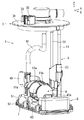
以下に、本発明を実施するための形態について、適宜図面を用いながら説明する。なお、本明細書における前後方向、上下方向、左右方向などの方向は、図1などに示したXが前方向、Yが左方向、Zが上方向と規定する。例えば、通常、燃料供給装置1の蓋部3が位置する側が上側でポンプユニット4が位置する側が下側となる。なお、以下においては、特に断りが無い限り、燃料供給装置1が燃料タンク9に装着されている状態であることを前提にして、方向について言及する。
Hereinafter, embodiments for carrying out the present invention will be described with reference to the drawings as appropriate. In the present specification, directions such as the front-rear direction, the up-down direction, and the left-right direction are defined such that X shown in FIG. 1 is the front direction, Y is the left direction, and Z is the up direction. For example, normally, the side where the
本実施の形態における燃料供給装置1は乗物に搭載されるものである。特に、乗物の中でも車両に搭載されるものである。燃料供給装置1は、車両の床面よりも下方に配置した燃料タンク9に取り付けられるものであり、燃料タンク9内の液体燃料を図示しない内燃機関に送液するために使用されるものである。
The
本実施例における燃料供給装置1は、燃料タンク9の上面部91に設けられた開口部92に取り付けられる蓋部3と、燃料タンク9内の燃料を外部に送液するために使用される燃料ポンプ41を備えたポンプユニット4と、燃料タンク9の底面部93と当接可能なベース部5と、蓋部3とベース部5とを連結するために使用される連結部6とを備えている。本実施例の燃料供給装置1は、燃料タンク9の開口部92に蓋部3を取り付けることにより、燃料タンク9の開口部92を閉じることが可能であるとともに、ベース部5を燃料タンク9の底面部93に沿って設置可能なものである(図2参照)。
The
本実施例の蓋部3は、燃料タンク9の開口部92を覆うことになるセットプレート部31を備えている。略円盤形状のセットプレート部31には、ポンプユニット4から送液された燃料を燃料タンク9外に導くために使用される吐出ポート33が備えられている。またセットプレート部31には、電気配線の接続のために使用される電気コネクタ35が備えられている。燃料タンク9の開口部92は通常円形であるため、蓋部3のセットプレート部31も平面視で略円形となるように形成されている。燃料タンク9に設けられた円形の開口部92にはシール材としてOリングなどの樹脂製のリング(図示せず)が取り付けられており、燃料タンク9と蓋部3との間に隙間が生じることを抑制している。
The
本実施例の燃料供給装置1は、連結部6が伸縮可能に構成されている。連結部6は蓋部3に取り付けた棒部材61と、棒部材61に沿って移動可能なジョイント部63を備えている。当該棒部材61はセットプレート部31が広がる面方向に対して直交するように伸びるものである。また、ジョイント部63と蓋部3との間には弾性力を発揮可能な部材としてスプリング(図示せず)を備えている。当該スプリングは、蓋部3とポンプユニット4が所定の間隔よりも近接した際に、蓋部3とポンプユニット4を離間させるように付勢可能なものである。したがって、ポンプユニット4の底面が燃料タンク9の底面部93に接した状態から更に蓋部3を燃料タンク9の底面部93に近づけるように移動させる間にスプリングは縮むことになる。このスプリングが縮んだ状態が維持されると、ポンプユニット4が燃料タンク9の底面部93に対して押し続けられた状態が維持されることになる。
The
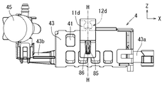
本実施例の燃料供給装置1には、蓋部3の下方にポンプユニット4が備えられている。本実施例のポンプユニット4は、燃料を送液するために使用される燃料ポンプ41と、燃料ポンプ41を覆う略円筒形状のポンプケーシング43と、圧力調整弁(図示せず)と、圧力調整弁用ケース45を備えている。ポンプユニット4は燃料ポンプ41を中心に、燃料ポンプ41に対して相対移動不能な部位で構成されている。なお、ポンプユニット4にはろ過材73を備えるフィルタ部材7が接続されている。また、燃料ポンプ41に対して相対移動可能なホース81も接続されている。当該フィルタ部材7及びホース81はポンプユニット4ではない。
The
本実施例のポンプユニット4はベース部5の上方に位置するものである。本実施例のベース部5は略平板状に形成されており、ベース部5の一側面が燃料タンク9の底面部93と対向するように配置されるものである。ベース部5は燃料貯留部やサブタンクなどとも称されることがある部分であり、本実施例のベース部5は燃料ポンプ41の真下に位置するアッパベース51と、燃料タンク9の底面部93に接するロアベース52とを組み立てることにより構成されている。なお、アッパベース51とロアベース52はろ過材73を挟み込みように組み立てられている(図4〜図7参照)。ポンプユニット4には吸引口43aが備えられており、フィルタ部材7に備えられた接続部71と吸引口43aとが係合状態で接続される。接続部71と吸引口43aとが接続されているため、フィルタ部材7を通過した燃料を燃料ポンプ41により吸引することが可能となる。なお、当該接続部71はアッパベース51の開口部55に対して挿通された状態として配置されているが、接続部71は開口部位55と非接触の状態となるように配置されている。また、当該接続部71は吸引口43aとの間で比較的自由度が高い状態で接続されている。
The
ロアベース52の底面には図示しない開口が備えられている。ロアベース52を燃料タンク9の底面部93に接した状態で配置した場合でも、開口から燃料を吸い込むことができるように脚部58が設けられている。また、アッパベース51の外周はロアベース52の外周よりも一回り小さく構成されており、ろ過材73を挟み込まない状態においてはアッパベース51とロアベース52との間に隙間が生じるように構成されている。当該隙間は燃料をベース部5内に導入することが可能な隙間である。本実施例においては、アッパベース51の一側面をろ過材73により覆うように配置しているため、当該隙間からベース部5内に侵入する燃料についても、ろ過材73を通過した上で燃料ポンプ41まで到達する。なお、ろ過材73は略矩形状の不織布を重ね合わせ、周囲を接合したものであり、内部に空間が形成されるよう、図示しないフレームが不織布の間に配設されている。
An opening (not shown) is provided on the bottom surface of the
燃料ポンプ41により昇圧された燃料は、内燃機関に到達する前に燃料の送液圧力を調整するために使用される圧力調整弁(図示せず)を通過する。本実施例においては、圧力調整弁はポンプユニット4に備えられている。より詳しくは、圧力調整弁は燃料ポンプ41を覆うポンプケーシング43から伸びている弁支持部43bに取り付けられている。圧力調整弁で圧力が調整された燃料は、ホース81や吐出ポート33などを介して内燃機関に送られる。なお、圧力調整弁は、その外周が圧力調整弁用ケース45により被覆されている。
The fuel whose pressure has been increased by the
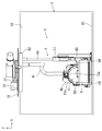
本実施例のベース部5には、荷重受け部11aが接続されており、当該荷重受け部11aとポンプユニット4との間には連接部12aが設けられている。前記連接部12aは、ポンプケーシング43の上方に位置しており、ポンプユニット4は吊り下げられた状態で支持されている。前記荷重受け部11aは、平板状の部材が側面視円弧状となるように構成されており、当該円弧の最上部から一つの連接部12aが真下に向けて伸びるように配置されている。
A
本実施例の連接部12aの前後方向の長さは平板状の部材の前後幅と略同じ長さに構成されている。このような長さで前後方向に伸びる略直方体状の連接部12aにより、ポンプユニット4と荷重受け部11aが連接されている。なお、本実施例においては、連接部12aの長手方向と、燃料ポンプ41の回転軸Rの方向は双方ともが前後方向となり、一致する(図3参照)。
The length of the connecting
荷重受け部11aは、燃料ポンプ41の振動が連接部12aを介して伝えられ得る部位である。当該振動がベース部5に伝わることを抑制するため、本実施例においては、弾性変形可能な部材を用いて荷重受け部11aを形成している。また、荷重受け部11aは板状の部位における左右方向の略中心位置において、燃料ポンプ41内蔵のポンプケーシング43を吊り下げ支持している。当該荷重受け部11aはアッパベース51の上面側に両端部が接続されており、荷重受け部11aは、ポンプユニット4の一部を跨ぐ様に配置される。つまり、アッパベース51と荷重受け部11aにより形成される筒状の部位の内側にポンプユニット4が配置された状態で、ポンプユニット4は宙吊りとなるように吊り下げられる。
The
本実施例のポンプユニット4はベース部5の底面と略平行となるように、その長手方向が位置する構成であり、いわゆる横置き状態とされるものである。燃料ポンプ41は、回転体41aであるインペラを回転させることで燃料を送液可能なものであるが、当該インペラの回転軸Rは、ポンプユニット4の長手方向と略一致しており、ベース部5の底面と略平行となっている。回転体41aを回転させると、ポンプユニット4は、概略、その重心Gの位置を固定するように回転軸Rの両端側が回転するように動こうとする(図12参照)。したがって、ポンプユニット4の重心Gから回転軸R方向に離れていくほど、ポンプユニット4は動きが大きいことになる。言い換えると、「燃料ポンプ41の回転軸Rの軸線と直交するとともに、前記ポンプユニット4の重心Gを通る仮想面S」が横断可能な位置は、ポンプユニット4が動きにくい位置となる。本実施例においては、当該位置に連接部12aが位置するように構成としている。
The
本実施例の連接部12aはポンプユニット4の重心Gの真上に位置する。ポンプユニット4に収納されている燃料ポンプ41が運転していない状態における回転体41aの回転軸Rと直交する面のうち、ポンプユニット4の重心Gを通る仮想面Sが横断できる位置に連接部12aが配置されている。したがって、燃料ポンプ41が動いても、連接部12aが大きく振れることは抑制される。なお、本実施例においては、重心Gより真上に延びる仮想直線が貫通可能な位置に連接部12aが配置されており、当該仮想直線は、ベース部5がタンクユニットに当接する当接面と直交する位置関係となる。
The connecting
本実施例におけるポンプユニット4は吊り下げられる構造である。そのため連接部12aは、燃料ポンプ41の上方に向けて伸びるように形成されている。また、燃料ポンプ41の上方側にのみ連接部12aがあり、対応する位置である燃料ポンプ41の下方側には連接部は存在しない。ポンプユニット4を吊り下げる構成であるため、荷重受け部11aから下方に伸びる連接部12aはポンプユニット4に対して真上に向けた力を与えるように働く。したがって、ポンプユニット4の静止時においては、連接部12aは主として引っ張り応力がかかるものとなり、常に大きなせん断応力が連接部12aにかかるようなことは回避され得る。そのため、連接部12aの形態などの自由度を高めることが可能となり得る。
The
連接部12aとポンプユニット4の重心Gとの関係は、本実施例のように、連接部12aの一部がポンプユニット4の重心Gの真上に存在するものであることが好ましい。また、連接部12aの回転軸R方向の中心位置が、前記仮想面Sが横断可能な位置となることが望ましい。
The relationship between the connecting
荷重受け部11aと連接部12aとの接続は、複数個所で接続することも可能であるが、本実施例のように一箇所で行われることが望ましい。荷重受け部11aと連接部12aが接続される箇所が低減されると、振動の伝播経路の数が低減されるからである。
Although the
ところで、荷重受け部11aとベース部5は凹部85に凸部86が挿入された状態で接続されている。当該接続は、圧入などとは異なり、凹部85と凸部86との間に若干の隙間が形成される。したがって、密着状態と異なり、荷重受け部11aとベース部5との間に若干のがたつきが生じる。このため、荷重受け部11aからベース部5に対して振動が伝わることが抑制可能となり得る。
By the way, the
本実施例においては、荷重受け部11aに設けられた凹部85に対してベース部5に設けられた凸部86が挿入された状態となることにより荷重受け部11aとベース部5が接続されている。より詳しくは、ベース部5に設けられた凸部位83の一部に凸部86が設けられており、荷重受け部11aの端部に設けられ凸部位83を挟み込むことが可能な挟み込み部位84の一部に凹部85が設けられている。このため、挟み込み部位84を構成する板状の部位同士の間で荷重受け部11aの一方向の挙動範囲が定まる。したがって、凹部85と凸部86との間で荷重受け部11aの前記一方向以外の挙動範囲を定めればよく、凸部86の周囲全体が凹部85に密着していなくても荷重受け部11aとベース部5が分離することを抑制することができる。よって、凹部85内において凸部86が挙動することが可能となり得る。なお、本実施例においては、挟み込み部位84により荷重受け部11aが左右方向に動く範囲を抑制しており。左右方向に突出した凸部86が凹部85より抜け落ちることが抑制されている。
In the present embodiment, the
本実施例の燃料供給装置1であると、アッパベース51とロアベース52が可撓性のろ過材73を挟み込む構成であるため、より一層、燃料タンク9に振動を発生させることを抑制しうる。また、本実施例においてはアッパベース51もろ過材73も弾性変形可能なものであるため、更に、燃料タンク9に振動を発生させることを抑制しうる。
In the
上記実施例に記載した態様のほか、以下に記すような変形例とすることも可能である。図8に示す変形例1のように、荷重受け部11bを複数回屈曲するように形成することも可能である。変形例1の場合、荷重受け部11bの一部は側面視において略S字状に屈曲している。このように構成すると、弾性変形可能な荷重受け部11bの長さを比較的長くすることが可能となるため、振動の吸収を効果的に行い易くなり得る。また、形状に起因して弾性変形可能となり得るため、当該面からしても振動を吸収しやすくなり得る。変形例1においては、連接部12bの両側に当該屈曲が形成されている。特に側面視において、連接部12bを通る線を対称軸とする線対象となるように形成されており、荷重受け部11bと連接部12bが接続する部位が略T字状に形成されている。変形例1では、上下方向に折りたたむように屈曲されており、荷重受け部11bは比較的上下方向に変形し易くなり得る。
In addition to the embodiments described in the above embodiments, the following modifications may be made. It is also possible to form the
図9に示す変形例2のように、荷重受け部11cの屈曲を左右方向に向けて形成することも可能である。変形例2においては、連接部12cの両側に当該屈曲が形成されている。特に平面視において、連接部12cを通る線を対称軸とする線対象となるように屈曲が形成されている。変形例2においては、左右方向に折りたたむように屈曲されており、荷重受け部11cは比較的上下方向に変形し易く構成されている。変形例2の構成においては、荷重受け部11cが側面視において円弧形状でありながら、荷重受け部11cの長さを比較的長めに形成することが可能となるため、荷重受け部11cが各所に衝突する可能性を抑制しながら、振動の伝達をより効果的に抑制することが可能となり得る。
As in the second modification shown in FIG. 9, the
図10及び図11に示す変形例3のように、連接部12dを組立構造とすることも可能である。荷重受け部11d側の部位とポンプユニット4側の部位を嵌合状態で組み立てるようにすれば、各々の部位が繋がる部分にがたつきが生じることにより、振動の伝達を低下させることが可能となり得る。また、連接部12dが屈曲可能な構成とすれば、燃料ポンプ41が運転されることでポンプユニット4が動いた場合に、連接部12dが屈曲することにより、荷重受け部11dに振動が伝わることが抑制され得る。また、ポンプユニット4を吊り下げた際の吊り下げ中心軸H上の所定箇所を中心としてポンプユニット4が揺動できる構成とすると良い。例えば、略球形状の部位と、当該部位を包み込むように嵌め込む事が可能な凹形状の部位とを嵌合させることで、ボール継ぎ手状の可動部をつくれば、当該構成とすることが可能である。当該構成とすれば、連接部12dにおいても、効果的に振動を減衰しうる。
As in
以上、幾つかの実施例を用いて実施形態を説明したが、本発明は、上記実施形態のほか、その他各種の形態で実施可能なものである。例えば、連接部は一箇所だけ設けるものとする必要は無く、複数個所に設けることが可能である。例えば、回転軸と直交する方向に並ぶように複数個所設けることも可能であるし、回転軸に沿って複数個所に設けることも可能である。仮想面が横断できる位置に、複数個所の連接部の全てが配置されても良いし、その中の一部だけを配置するものとしても良い。 As mentioned above, although embodiment was described using some Examples, this invention can be implemented with other various forms besides the said embodiment. For example, it is not necessary to provide the connecting portion only at one place, and it can be provided at a plurality of places. For example, a plurality of locations can be provided so as to be aligned in a direction orthogonal to the rotation axis, or a plurality of locations can be provided along the rotation axis. All of the connecting portions at a plurality of positions may be arranged at a position where the virtual plane can be crossed, or only a part of them may be arranged.
連接部は、ポンプユニットの重心の真上に位置する構成でなくても良い。例えば、若干左右方向や前後方向にずれた箇所に位置する構成とすることも可能である。 The connecting portion may not be configured to be located directly above the center of gravity of the pump unit. For example, it may be configured to be located at a position slightly shifted in the left-right direction or the front-rear direction.
荷重受け部は、弾性変形する必要は無く、剛体で形成することも可能である。ただし、弾性変形できる構造であるほうが、燃料タンクなどに振動を伝えることを抑制し易くなる。 The load receiving portion does not need to be elastically deformed and can be formed of a rigid body. However, the structure that can be elastically deformed makes it easier to suppress the transmission of vibration to the fuel tank or the like.
荷重受け部は両端がベース部に嵌めこまれて接続している構成である必要性は無い。荷重受け部とベース部をネジで固定することや、荷重受け部とベース部を一体成形することなども可能である。 The load receiving portion need not have a configuration in which both ends are fitted and connected to the base portion. It is also possible to fix the load receiving portion and the base portion with screws, or to integrally form the load receiving portion and the base portion.
荷重受け部とベース部は分離可能な構造である必要性は無く、分離不能な一続きの部材として構成されていても良い。ただし、分離可能な構造であると、荷重受け部の弾性を調整し易い。また、振動の減衰を抑制する構造とすることが比較的容易となり得る。 The load receiving portion and the base portion need not be separable structures, and may be configured as a continuous member that cannot be separated. However, if the structure is separable, it is easy to adjust the elasticity of the load receiving portion. In addition, a structure that suppresses vibration damping can be relatively easy.
ベース部は、アッパベースとロアベースによりろ過材を挟み込んだ形態のものである必要性は無く、ロアベース及び/又はろ過材が備えられていないものとすることが可能である。 There is no need for the base portion to have a configuration in which the filter medium is sandwiched between the upper base and the lower base, and the lower base and / or the filter medium can be omitted.
また、荷重受け部に凹部を構成し、ベース部に凸部を構成することに限ることは無く、荷重受け部に凸部を構成し、ベース部に凹部を構成することも可能である。 In addition, the load receiving portion is not limited to the concave portion and the base portion is not limited to the convex portion, and the load receiving portion may be configured to have the convex portion and the base portion may be configured to be the concave portion.
また、乗物としては、車両であることに限らず、飛行機やヘリコプターなど空中を飛行する乗物や、船舶や潜水艇など海面や海中などを移動する乗物としてもよい。 The vehicle is not limited to a vehicle, and may be a vehicle that flies in the air such as an airplane or a helicopter, or a vehicle that moves on the sea surface or in the sea such as a ship or a submersible.
1 燃料供給装置
4 ポンプユニット
5 ベース部
7 フィルタ部材
9 燃料タンク
11a 荷重受け部
11b 荷重受け部
11c 荷重受け部
11d 荷重受け部
12a 連接部
12b 連接部
12c 連接部
12d 連接部
41 燃料ポンプ
41a 回転体
43 ポンプケーシング
45 圧力調整弁用ケース
85 凹部
86 凸部
G 重心
R 回転軸
S 仮想面
DESCRIPTION OF
Claims (8)
前記荷重受け部と、前記ポンプユニットとの間に、前記荷重受け部と前記ポンプユニットを連接する連接部を備えることで前記ポンプユニットが吊り下げ支持可能とされており、
前記燃料ポンプの回転体の回転軸と直交するとともに前記ポンプユニットの重心を通る仮想面が横断可能な位置に、前記連接部が配置されており、
前記連接部は、前記荷重受け部から前記ポンプユニットに向かって真下に向けて延びるように配置されている燃料供給装置。 A fuel supply device comprising: a pump unit including a fuel pump having a rotating body that rotates about a rotating shaft; and a load receiving portion capable of receiving a load of the pump unit,
The pump unit can be suspended and supported by providing a connecting portion that connects the load receiving portion and the pump unit between the load receiving portion and the pump unit.
The connecting portion is disposed at a position that is perpendicular to the rotation axis of the rotating body of the fuel pump and that can cross a virtual plane that passes through the center of gravity of the pump unit ,
The fuel supply device , wherein the connecting portion is disposed so as to extend downward from the load receiving portion toward the pump unit .
前記荷重受け部と、前記ポンプユニットとの間に、前記荷重受け部と前記ポンプユニットを連接する連接部を備えることで前記ポンプユニットが吊り下げ支持可能とされており、The pump unit can be suspended and supported by providing a connecting portion that connects the load receiving portion and the pump unit between the load receiving portion and the pump unit.
前記燃料ポンプの回転体の回転軸と直交するとともに前記ポンプユニットの重心を通る仮想面が横断可能な位置に、前記連接部が配置されており、The connecting portion is disposed at a position that is perpendicular to the rotation axis of the rotating body of the fuel pump and that can cross a virtual plane that passes through the center of gravity of the pump unit,
前記連接部が接続されている個所における前記荷重受け部の上面は、前記回転軸の方向から見て凹状に形成されている燃料供給装置。The fuel supply device, wherein an upper surface of the load receiving portion at a location where the connecting portion is connected is formed in a concave shape when viewed from the direction of the rotating shaft.
前記荷重受け部と、前記ポンプユニットとの間に、前記荷重受け部と前記ポンプユニットを連接する連接部を備えることで前記ポンプユニットが吊り下げ支持可能とされており、The pump unit can be suspended and supported by providing a connecting portion that connects the load receiving portion and the pump unit between the load receiving portion and the pump unit.
前記燃料ポンプの回転体の回転軸と直交するとともに前記ポンプユニットの重心を通る仮想面が横断可能な位置に、前記連接部が配置されており、The connecting portion is disposed at a position that is perpendicular to the rotation axis of the rotating body of the fuel pump and that can cross a virtual plane that passes through the center of gravity of the pump unit,
前記荷重受け部と前記連接部とが接続されている部位は、前記回転軸の方向から見て略T字状に形成されている燃料供給装置。The portion where the load receiving portion and the connecting portion are connected is a fuel supply device formed in a substantially T shape when viewed from the direction of the rotation shaft.
前記連接部は1個所であり、当該1個所の前記連接部にて前記ポンプユニットが前記荷重受け部に吊り下げ支持されている燃料供給装置。1. The fuel supply apparatus according to claim 1, wherein the connecting portion is provided at one location, and the pump unit is suspended and supported by the load receiving portion at the one connecting portion.
前記荷重受け部は、弾性体を用いて構成されている燃料供給装置。 The fuel supply device according to any one of claims 1 to 4 ,
The load receiving portion is a fuel supply device configured using an elastic body.
前記荷重受け部は、前記回転軸の方向から見て弧形状である燃料供給装置。 The fuel supply device according to any one of claims 1 to 5 ,
The fuel supply device, wherein the load receiving portion has an arc shape when viewed from the direction of the rotation shaft .
前記荷重受け部の一部にS字状の部位を備える燃料供給装置。 The fuel supply device according to any one of claims 1 to 6 ,
A fuel supply apparatus comprising an S-shaped part in a part of the load receiving part.
前記荷重受け部の一端及び他端は、凹部に凸部が挿入された状態でベース部に係止される燃料供給装置。 The fuel supply device according to any one of claims 1 to 7 ,
A fuel supply device in which one end and the other end of the load receiving portion are locked to the base portion in a state where a convex portion is inserted into the concave portion.
Priority Applications (5)
| Application Number | Priority Date | Filing Date | Title |
|---|---|---|---|
| JP2014224092A JP6282573B2 (en) | 2014-11-04 | 2014-11-04 | Fuel supply device |
| CN201580056774.9A CN107076070B (en) | 2014-11-04 | 2015-10-08 | Fuel supply system |
| PCT/JP2015/078646 WO2016072210A1 (en) | 2014-11-04 | 2015-10-08 | Fuel supply device |
| US15/521,729 US10648435B2 (en) | 2014-11-04 | 2015-10-08 | Fuel supply devices |
| DE112015004561.9T DE112015004561B4 (en) | 2014-11-04 | 2015-10-08 | Fuel supply devices |
Applications Claiming Priority (1)
| Application Number | Priority Date | Filing Date | Title |
|---|---|---|---|
| JP2014224092A JP6282573B2 (en) | 2014-11-04 | 2014-11-04 | Fuel supply device |
Publications (2)
| Publication Number | Publication Date |
|---|---|
| JP2016089691A JP2016089691A (en) | 2016-05-23 |
| JP6282573B2 true JP6282573B2 (en) | 2018-02-21 |
Family
ID=55908937
Family Applications (1)
| Application Number | Title | Priority Date | Filing Date |
|---|---|---|---|
| JP2014224092A Active JP6282573B2 (en) | 2014-11-04 | 2014-11-04 | Fuel supply device |
Country Status (5)
| Country | Link |
|---|---|
| US (1) | US10648435B2 (en) |
| JP (1) | JP6282573B2 (en) |
| CN (1) | CN107076070B (en) |
| DE (1) | DE112015004561B4 (en) |
| WO (1) | WO2016072210A1 (en) |
Families Citing this family (2)
| Publication number | Priority date | Publication date | Assignee | Title |
|---|---|---|---|---|
| JP6907145B2 (en) * | 2018-03-28 | 2021-07-21 | 愛三工業株式会社 | Fuel supply device |
| CN109340002B (en) * | 2018-11-14 | 2024-01-19 | 江苏舒尔驰精密金属成形有限公司 | Fixed subassembly of lightweight oil tank fuel pump |
Family Cites Families (12)
| Publication number | Priority date | Publication date | Assignee | Title |
|---|---|---|---|---|
| JPS51126821U (en) | 1975-04-09 | 1976-10-14 | ||
| US5038741A (en) * | 1990-04-13 | 1991-08-13 | Walbro Corporation | In-tank fuel module |
| US5875816A (en) * | 1996-05-17 | 1999-03-02 | Robert Bosch Gmbh | Fuel feeding module with integrated fuel fine filter |
| JP3698293B2 (en) * | 1999-02-18 | 2005-09-21 | 株式会社デンソー | Rotating device support structure and fuel supply device using the same |
| JP2001082274A (en) | 1999-09-16 | 2001-03-27 | Keihin Corp | Fuel supply system |
| ATE306018T1 (en) | 2002-12-20 | 2005-10-15 | Delphi Tech Inc | VIBRATION ISOLATING FUEL PUMP UNIT |
| JP2008088814A (en) * | 2006-09-29 | 2008-04-17 | Aisan Ind Co Ltd | Vibration attenuation device for fuel pump |
| JP4613917B2 (en) | 2007-03-07 | 2011-01-19 | 三菱電機株式会社 | Fuel supply device |
| JP2009127471A (en) | 2007-11-21 | 2009-06-11 | Aisan Ind Co Ltd | Fuel supply device |
| JP5630371B2 (en) * | 2010-09-13 | 2014-11-26 | 株式会社デンソー | Fuel supply device |
| JP5826660B2 (en) * | 2011-02-17 | 2015-12-02 | 愛三工業株式会社 | Fuel supply device |
| JP6239393B2 (en) * | 2014-01-27 | 2017-11-29 | 愛三工業株式会社 | Fuel pump |
-
2014
- 2014-11-04 JP JP2014224092A patent/JP6282573B2/en active Active
-
2015
- 2015-10-08 CN CN201580056774.9A patent/CN107076070B/en active Active
- 2015-10-08 DE DE112015004561.9T patent/DE112015004561B4/en active Active
- 2015-10-08 US US15/521,729 patent/US10648435B2/en active Active
- 2015-10-08 WO PCT/JP2015/078646 patent/WO2016072210A1/en active Application Filing
Also Published As
| Publication number | Publication date |
|---|---|
| US20170248105A1 (en) | 2017-08-31 |
| JP2016089691A (en) | 2016-05-23 |
| WO2016072210A1 (en) | 2016-05-12 |
| CN107076070A (en) | 2017-08-18 |
| DE112015004561T5 (en) | 2017-07-13 |
| CN107076070B (en) | 2019-04-30 |
| US10648435B2 (en) | 2020-05-12 |
| DE112015004561B4 (en) | 2021-07-08 |
Similar Documents
| Publication | Publication Date | Title |
|---|---|---|
| US10046634B2 (en) | Engine mount structure | |
| JP6297451B2 (en) | Fuel supply device | |
| JP6258158B2 (en) | Fuel supply device | |
| JP6301234B2 (en) | Fuel supply device | |
| JP6355255B2 (en) | Vibration isolator | |
| JP6282573B2 (en) | Fuel supply device | |
| JP6608331B2 (en) | Fuel supply device | |
| KR101544297B1 (en) | Installation device for instrumentation device of stationary engine | |
| KR20160060598A (en) | Controller assembly and work machine cab | |
| CN104608697B (en) | The positioner of automobile rear view mirror driver | |
| WO2018163596A1 (en) | Vibration-proof device and vibration-proof engine | |
| KR20130073645A (en) | High damping vertical dynamic absorber | |
| JP6469497B2 (en) | Vibration isolator | |
| JP5094300B2 (en) | Multiple types of vibration isolator | |
| JP6543144B2 (en) | Vibration control device | |
| JP2009058056A (en) | Cylindrical member for vibration-proof device, and vibration-proof device | |
| JP5621719B2 (en) | Electric compressor mounting structure | |
| JP5121750B2 (en) | Vibration isolator and its mounting structure | |
| JP2008196574A (en) | Liquid filled type vibration isolating device | |
| JP5038264B2 (en) | Dynamic damper | |
| JP5013212B2 (en) | Dynamic damper and its mounting structure | |
| JP2010091042A (en) | Vibration damper | |
| KR101551012B1 (en) | Fuel pump for vehicle | |
| JP2015093584A (en) | Power source support structure of vehicle | |
| JP2015129575A (en) | Vibration isolator |
Legal Events
| Date | Code | Title | Description |
|---|---|---|---|
| A621 | Written request for application examination |
Free format text: JAPANESE INTERMEDIATE CODE: A621 Effective date: 20170314 |
|
| A131 | Notification of reasons for refusal |
Free format text: JAPANESE INTERMEDIATE CODE: A131 Effective date: 20171114 |
|
| A521 | Request for written amendment filed |
Free format text: JAPANESE INTERMEDIATE CODE: A523 Effective date: 20171226 |
|
| TRDD | Decision of grant or rejection written | ||
| A01 | Written decision to grant a patent or to grant a registration (utility model) |
Free format text: JAPANESE INTERMEDIATE CODE: A01 Effective date: 20180109 |
|
| A61 | First payment of annual fees (during grant procedure) |
Free format text: JAPANESE INTERMEDIATE CODE: A61 Effective date: 20180124 |
|
| R150 | Certificate of patent or registration of utility model |
Ref document number: 6282573 Country of ref document: JP Free format text: JAPANESE INTERMEDIATE CODE: R150 |
|
| R250 | Receipt of annual fees |
Free format text: JAPANESE INTERMEDIATE CODE: R250 |
|
| R250 | Receipt of annual fees |
Free format text: JAPANESE INTERMEDIATE CODE: R250 |