JP6281254B2 - Vibration element, vibrator, oscillator, electronic device, and moving object - Google Patents
Vibration element, vibrator, oscillator, electronic device, and moving object Download PDFInfo
- Publication number
- JP6281254B2 JP6281254B2 JP2013237479A JP2013237479A JP6281254B2 JP 6281254 B2 JP6281254 B2 JP 6281254B2 JP 2013237479 A JP2013237479 A JP 2013237479A JP 2013237479 A JP2013237479 A JP 2013237479A JP 6281254 B2 JP6281254 B2 JP 6281254B2
- Authority
- JP
- Japan
- Prior art keywords
- vibration element
- vibration
- vibrating
- vibrating arm
- value
- Prior art date
- Legal status (The legal status is an assumption and is not a legal conclusion. Google has not performed a legal analysis and makes no representation as to the accuracy of the status listed.)
- Active
Links
- 230000010355 oscillation Effects 0.000 claims description 4
- 239000013078 crystal Substances 0.000 description 35
- 238000004088 simulation Methods 0.000 description 33
- 239000010453 quartz Substances 0.000 description 28
- VYPSYNLAJGMNEJ-UHFFFAOYSA-N silicon dioxide Inorganic materials O=[Si]=O VYPSYNLAJGMNEJ-UHFFFAOYSA-N 0.000 description 28
- 230000014509 gene expression Effects 0.000 description 27
- 241000251131 Sphyrna Species 0.000 description 22
- 238000005452 bending Methods 0.000 description 17
- 238000001039 wet etching Methods 0.000 description 15
- 238000006243 chemical reaction Methods 0.000 description 12
- 239000000853 adhesive Substances 0.000 description 11
- 230000001070 adhesive effect Effects 0.000 description 11
- 239000000463 material Substances 0.000 description 10
- 239000011651 chromium Substances 0.000 description 9
- 230000000694 effects Effects 0.000 description 9
- 239000000758 substrate Substances 0.000 description 9
- 239000010931 gold Substances 0.000 description 8
- 238000000034 method Methods 0.000 description 8
- PXHVJJICTQNCMI-UHFFFAOYSA-N nickel Substances [Ni] PXHVJJICTQNCMI-UHFFFAOYSA-N 0.000 description 8
- 239000000470 constituent Substances 0.000 description 7
- 230000006870 function Effects 0.000 description 6
- 230000006872 improvement Effects 0.000 description 6
- 238000005530 etching Methods 0.000 description 5
- 238000003384 imaging method Methods 0.000 description 5
- 238000000926 separation method Methods 0.000 description 5
- XLOMVQKBTHCTTD-UHFFFAOYSA-N Zinc monoxide Chemical compound [Zn]=O XLOMVQKBTHCTTD-UHFFFAOYSA-N 0.000 description 4
- 239000010949 copper Substances 0.000 description 4
- 238000012937 correction Methods 0.000 description 4
- 229910052751 metal Inorganic materials 0.000 description 4
- 239000002184 metal Substances 0.000 description 4
- 230000003287 optical effect Effects 0.000 description 4
- 238000000059 patterning Methods 0.000 description 4
- 229910052709 silver Inorganic materials 0.000 description 4
- 239000004332 silver Substances 0.000 description 4
- 238000012546 transfer Methods 0.000 description 4
- XEEYBQQBJWHFJM-UHFFFAOYSA-N Iron Chemical compound [Fe] XEEYBQQBJWHFJM-UHFFFAOYSA-N 0.000 description 3
- BQCADISMDOOEFD-UHFFFAOYSA-N Silver Chemical compound [Ag] BQCADISMDOOEFD-UHFFFAOYSA-N 0.000 description 3
- 230000004308 accommodation Effects 0.000 description 3
- 238000013459 approach Methods 0.000 description 3
- 229910052804 chromium Inorganic materials 0.000 description 3
- 238000004891 communication Methods 0.000 description 3
- 230000007423 decrease Effects 0.000 description 3
- 238000002474 experimental method Methods 0.000 description 3
- 229910052737 gold Inorganic materials 0.000 description 3
- 238000000206 photolithography Methods 0.000 description 3
- BASFCYQUMIYNBI-UHFFFAOYSA-N platinum Chemical compound [Pt] BASFCYQUMIYNBI-UHFFFAOYSA-N 0.000 description 3
- 239000010936 titanium Substances 0.000 description 3
- XKRFYHLGVUSROY-UHFFFAOYSA-N Argon Chemical compound [Ar] XKRFYHLGVUSROY-UHFFFAOYSA-N 0.000 description 2
- IJGRMHOSHXDMSA-UHFFFAOYSA-N Atomic nitrogen Chemical compound N#N IJGRMHOSHXDMSA-UHFFFAOYSA-N 0.000 description 2
- VYZAMTAEIAYCRO-UHFFFAOYSA-N Chromium Chemical compound [Cr] VYZAMTAEIAYCRO-UHFFFAOYSA-N 0.000 description 2
- RYGMFSIKBFXOCR-UHFFFAOYSA-N Copper Chemical compound [Cu] RYGMFSIKBFXOCR-UHFFFAOYSA-N 0.000 description 2
- 238000004458 analytical method Methods 0.000 description 2
- 238000004364 calculation method Methods 0.000 description 2
- 230000001413 cellular effect Effects 0.000 description 2
- 239000000919 ceramic Substances 0.000 description 2
- 230000008859 change Effects 0.000 description 2
- 230000008602 contraction Effects 0.000 description 2
- 229910052802 copper Inorganic materials 0.000 description 2
- 230000008878 coupling Effects 0.000 description 2
- 238000010168 coupling process Methods 0.000 description 2
- 238000005859 coupling reaction Methods 0.000 description 2
- 238000006073 displacement reaction Methods 0.000 description 2
- 230000005684 electric field Effects 0.000 description 2
- 238000005516 engineering process Methods 0.000 description 2
- PCHJSUWPFVWCPO-UHFFFAOYSA-N gold Chemical compound [Au] PCHJSUWPFVWCPO-UHFFFAOYSA-N 0.000 description 2
- 229910052451 lead zirconate titanate Inorganic materials 0.000 description 2
- 239000007769 metal material Substances 0.000 description 2
- 229910052759 nickel Inorganic materials 0.000 description 2
- 239000010955 niobium Substances 0.000 description 2
- 230000035515 penetration Effects 0.000 description 2
- 229920002120 photoresistant polymer Polymers 0.000 description 2
- WFKWXMTUELFFGS-UHFFFAOYSA-N tungsten Chemical compound [W] WFKWXMTUELFFGS-UHFFFAOYSA-N 0.000 description 2
- 229910052721 tungsten Inorganic materials 0.000 description 2
- 239000010937 tungsten Substances 0.000 description 2
- 239000011787 zinc oxide Substances 0.000 description 2
- NAWXUBYGYWOOIX-SFHVURJKSA-N (2s)-2-[[4-[2-(2,4-diaminoquinazolin-6-yl)ethyl]benzoyl]amino]-4-methylidenepentanedioic acid Chemical compound C1=CC2=NC(N)=NC(N)=C2C=C1CCC1=CC=C(C(=O)N[C@@H](CC(=C)C(O)=O)C(O)=O)C=C1 NAWXUBYGYWOOIX-SFHVURJKSA-N 0.000 description 1
- XQUPVDVFXZDTLT-UHFFFAOYSA-N 1-[4-[[4-(2,5-dioxopyrrol-1-yl)phenyl]methyl]phenyl]pyrrole-2,5-dione Chemical compound O=C1C=CC(=O)N1C(C=C1)=CC=C1CC1=CC=C(N2C(C=CC2=O)=O)C=C1 XQUPVDVFXZDTLT-UHFFFAOYSA-N 0.000 description 1
- WSMQKESQZFQMFW-UHFFFAOYSA-N 5-methyl-pyrazole-3-carboxylic acid Chemical compound CC1=CC(C(O)=O)=NN1 WSMQKESQZFQMFW-UHFFFAOYSA-N 0.000 description 1
- 241000251468 Actinopterygii Species 0.000 description 1
- 229910001316 Ag alloy Inorganic materials 0.000 description 1
- 229910000838 Al alloy Inorganic materials 0.000 description 1
- PIGFYZPCRLYGLF-UHFFFAOYSA-N Aluminum nitride Chemical compound [Al]#N PIGFYZPCRLYGLF-UHFFFAOYSA-N 0.000 description 1
- JBRZTFJDHDCESZ-UHFFFAOYSA-N AsGa Chemical compound [As]#[Ga] JBRZTFJDHDCESZ-UHFFFAOYSA-N 0.000 description 1
- 229910001020 Au alloy Inorganic materials 0.000 description 1
- 229910000599 Cr alloy Inorganic materials 0.000 description 1
- 239000004593 Epoxy Substances 0.000 description 1
- WQZGKKKJIJFFOK-GASJEMHNSA-N Glucose Natural products OC[C@H]1OC(O)[C@H](O)[C@@H](O)[C@@H]1O WQZGKKKJIJFFOK-GASJEMHNSA-N 0.000 description 1
- 229910013641 LiNbO 3 Inorganic materials 0.000 description 1
- ZOKXTWBITQBERF-UHFFFAOYSA-N Molybdenum Chemical compound [Mo] ZOKXTWBITQBERF-UHFFFAOYSA-N 0.000 description 1
- 229910003237 Na0.5Bi0.5TiO3 Inorganic materials 0.000 description 1
- 229910000990 Ni alloy Inorganic materials 0.000 description 1
- 239000004642 Polyimide Substances 0.000 description 1
- 101100364827 Prochlorococcus marinus (strain SARG / CCMP1375 / SS120) ahcY gene Proteins 0.000 description 1
- 101150081953 SAM1 gene Proteins 0.000 description 1
- 101150016293 SAM4 gene Proteins 0.000 description 1
- XUIMIQQOPSSXEZ-UHFFFAOYSA-N Silicon Chemical compound [Si] XUIMIQQOPSSXEZ-UHFFFAOYSA-N 0.000 description 1
- RTAQQCXQSZGOHL-UHFFFAOYSA-N Titanium Chemical compound [Ti] RTAQQCXQSZGOHL-UHFFFAOYSA-N 0.000 description 1
- NIXOWILDQLNWCW-UHFFFAOYSA-N acrylic acid group Chemical group C(C=C)(=O)O NIXOWILDQLNWCW-UHFFFAOYSA-N 0.000 description 1
- 230000032683 aging Effects 0.000 description 1
- 229910045601 alloy Inorganic materials 0.000 description 1
- 239000000956 alloy Substances 0.000 description 1
- 229910052782 aluminium Inorganic materials 0.000 description 1
- XAGFODPZIPBFFR-UHFFFAOYSA-N aluminium Chemical compound [Al] XAGFODPZIPBFFR-UHFFFAOYSA-N 0.000 description 1
- 229910052786 argon Inorganic materials 0.000 description 1
- 229910002113 barium titanate Inorganic materials 0.000 description 1
- JRPBQTZRNDNNOP-UHFFFAOYSA-N barium titanate Chemical compound [Ba+2].[Ba+2].[O-][Ti]([O-])([O-])[O-] JRPBQTZRNDNNOP-UHFFFAOYSA-N 0.000 description 1
- 230000008901 benefit Effects 0.000 description 1
- 230000005540 biological transmission Effects 0.000 description 1
- 230000015572 biosynthetic process Effects 0.000 description 1
- 229910052797 bismuth Inorganic materials 0.000 description 1
- JCXGWMGPZLAOME-UHFFFAOYSA-N bismuth atom Chemical compound [Bi] JCXGWMGPZLAOME-UHFFFAOYSA-N 0.000 description 1
- FSAJRXGMUISOIW-UHFFFAOYSA-N bismuth sodium Chemical compound [Na].[Bi] FSAJRXGMUISOIW-UHFFFAOYSA-N 0.000 description 1
- 229910002115 bismuth titanate Inorganic materials 0.000 description 1
- 239000008280 blood Substances 0.000 description 1
- 210000004369 blood Anatomy 0.000 description 1
- 230000036772 blood pressure Effects 0.000 description 1
- 230000015556 catabolic process Effects 0.000 description 1
- 239000000788 chromium alloy Substances 0.000 description 1
- 229910017052 cobalt Inorganic materials 0.000 description 1
- 239000010941 cobalt Substances 0.000 description 1
- GUTLYIVDDKVIGB-UHFFFAOYSA-N cobalt atom Chemical compound [Co] GUTLYIVDDKVIGB-UHFFFAOYSA-N 0.000 description 1
- 239000011231 conductive filler Substances 0.000 description 1
- 238000011161 development Methods 0.000 description 1
- 230000018109 developmental process Effects 0.000 description 1
- PSHMSSXLYVAENJ-UHFFFAOYSA-N dilithium;[oxido(oxoboranyloxy)boranyl]oxy-oxoboranyloxyborinate Chemical compound [Li+].[Li+].O=BOB([O-])OB([O-])OB=O PSHMSSXLYVAENJ-UHFFFAOYSA-N 0.000 description 1
- NKZSPGSOXYXWQA-UHFFFAOYSA-N dioxido(oxo)titanium;lead(2+) Chemical compound [Pb+2].[O-][Ti]([O-])=O NKZSPGSOXYXWQA-UHFFFAOYSA-N 0.000 description 1
- 230000001747 exhibiting effect Effects 0.000 description 1
- 229910000154 gallium phosphate Inorganic materials 0.000 description 1
- LWFNJDOYCSNXDO-UHFFFAOYSA-K gallium;phosphate Chemical compound [Ga+3].[O-]P([O-])([O-])=O LWFNJDOYCSNXDO-UHFFFAOYSA-K 0.000 description 1
- 239000008103 glucose Substances 0.000 description 1
- 239000003353 gold alloy Substances 0.000 description 1
- 230000005484 gravity Effects 0.000 description 1
- 239000001307 helium Substances 0.000 description 1
- 229910052734 helium Inorganic materials 0.000 description 1
- SWQJXJOGLNCZEY-UHFFFAOYSA-N helium atom Chemical compound [He] SWQJXJOGLNCZEY-UHFFFAOYSA-N 0.000 description 1
- AMGQUBHHOARCQH-UHFFFAOYSA-N indium;oxotin Chemical compound [In].[Sn]=O AMGQUBHHOARCQH-UHFFFAOYSA-N 0.000 description 1
- 239000011261 inert gas Substances 0.000 description 1
- 229910052742 iron Inorganic materials 0.000 description 1
- 238000005304 joining Methods 0.000 description 1
- 229910000833 kovar Inorganic materials 0.000 description 1
- HFGPZNIAWCZYJU-UHFFFAOYSA-N lead zirconate titanate Chemical compound [O-2].[O-2].[O-2].[O-2].[O-2].[Ti+4].[Zr+4].[Pb+2] HFGPZNIAWCZYJU-UHFFFAOYSA-N 0.000 description 1
- GQYHUHYESMUTHG-UHFFFAOYSA-N lithium niobate Chemical compound [Li+].[O-][Nb](=O)=O GQYHUHYESMUTHG-UHFFFAOYSA-N 0.000 description 1
- 230000007774 longterm Effects 0.000 description 1
- 238000004519 manufacturing process Methods 0.000 description 1
- 229910052750 molybdenum Inorganic materials 0.000 description 1
- 239000011733 molybdenum Substances 0.000 description 1
- 238000012544 monitoring process Methods 0.000 description 1
- 229910052758 niobium Inorganic materials 0.000 description 1
- GUCVJGMIXFAOAE-UHFFFAOYSA-N niobium atom Chemical compound [Nb] GUCVJGMIXFAOAE-UHFFFAOYSA-N 0.000 description 1
- 229910052757 nitrogen Inorganic materials 0.000 description 1
- TWNQGVIAIRXVLR-UHFFFAOYSA-N oxo(oxoalumanyloxy)alumane Chemical compound O=[Al]O[Al]=O TWNQGVIAIRXVLR-UHFFFAOYSA-N 0.000 description 1
- 239000002245 particle Substances 0.000 description 1
- 230000000149 penetrating effect Effects 0.000 description 1
- 230000000704 physical effect Effects 0.000 description 1
- 229910052697 platinum Inorganic materials 0.000 description 1
- 229920003192 poly(bis maleimide) Polymers 0.000 description 1
- 229920000728 polyester Polymers 0.000 description 1
- 229920001721 polyimide Polymers 0.000 description 1
- 239000004814 polyurethane Substances 0.000 description 1
- 229920002635 polyurethane Polymers 0.000 description 1
- BITYAPCSNKJESK-UHFFFAOYSA-N potassiosodium Chemical compound [Na].[K] BITYAPCSNKJESK-UHFFFAOYSA-N 0.000 description 1
- 229910052700 potassium Inorganic materials 0.000 description 1
- UKDIAJWKFXFVFG-UHFFFAOYSA-N potassium;oxido(dioxo)niobium Chemical compound [K+].[O-][Nb](=O)=O UKDIAJWKFXFVFG-UHFFFAOYSA-N 0.000 description 1
- 230000002265 prevention Effects 0.000 description 1
- 238000012545 processing Methods 0.000 description 1
- 230000009467 reduction Effects 0.000 description 1
- 229920005989 resin Polymers 0.000 description 1
- 239000011347 resin Substances 0.000 description 1
- VSZWPYCFIRKVQL-UHFFFAOYSA-N selanylidenegallium;selenium Chemical compound [Se].[Se]=[Ga].[Se]=[Ga] VSZWPYCFIRKVQL-UHFFFAOYSA-N 0.000 description 1
- 229910052710 silicon Inorganic materials 0.000 description 1
- 239000010703 silicon Substances 0.000 description 1
- -1 silver halide Chemical class 0.000 description 1
- 238000005549 size reduction Methods 0.000 description 1
- 229910052708 sodium Inorganic materials 0.000 description 1
- 239000011734 sodium Substances 0.000 description 1
- UYLYBEXRJGPQSH-UHFFFAOYSA-N sodium;oxido(dioxo)niobium Chemical compound [Na+].[O-][Nb](=O)=O UYLYBEXRJGPQSH-UHFFFAOYSA-N 0.000 description 1
- 238000004544 sputter deposition Methods 0.000 description 1
- 230000035882 stress Effects 0.000 description 1
- 230000002195 synergetic effect Effects 0.000 description 1
- JBQYATWDVHIOAR-UHFFFAOYSA-N tellanylidenegermanium Chemical compound [Te]=[Ge] JBQYATWDVHIOAR-UHFFFAOYSA-N 0.000 description 1
- 230000002277 temperature effect Effects 0.000 description 1
- 229910052719 titanium Inorganic materials 0.000 description 1
- 238000007740 vapor deposition Methods 0.000 description 1
- 239000011701 zinc Substances 0.000 description 1
- 229910000859 α-Fe Inorganic materials 0.000 description 1
Images


Classifications
-
- H—ELECTRICITY
- H03—ELECTRONIC CIRCUITRY
- H03H—IMPEDANCE NETWORKS, e.g. RESONANT CIRCUITS; RESONATORS
- H03H9/00—Networks comprising electromechanical or electro-acoustic devices; Electromechanical resonators
- H03H9/15—Constructional features of resonators consisting of piezoelectric or electrostrictive material
- H03H9/21—Crystal tuning forks
- H03H9/215—Crystal tuning forks consisting of quartz
-
- H—ELECTRICITY
- H03—ELECTRONIC CIRCUITRY
- H03B—GENERATION OF OSCILLATIONS, DIRECTLY OR BY FREQUENCY-CHANGING, BY CIRCUITS EMPLOYING ACTIVE ELEMENTS WHICH OPERATE IN A NON-SWITCHING MANNER; GENERATION OF NOISE BY SUCH CIRCUITS
- H03B5/00—Generation of oscillations using amplifier with regenerative feedback from output to input
- H03B5/30—Generation of oscillations using amplifier with regenerative feedback from output to input with frequency-determining element being electromechanical resonator
- H03B5/32—Generation of oscillations using amplifier with regenerative feedback from output to input with frequency-determining element being electromechanical resonator being a piezoelectric resonator
-
- H—ELECTRICITY
- H03—ELECTRONIC CIRCUITRY
- H03H—IMPEDANCE NETWORKS, e.g. RESONANT CIRCUITS; RESONATORS
- H03H9/00—Networks comprising electromechanical or electro-acoustic devices; Electromechanical resonators
- H03H9/02—Details
- H03H9/02007—Details of bulk acoustic wave devices
- H03H9/02015—Characteristics of piezoelectric layers, e.g. cutting angles
- H03H9/02023—Characteristics of piezoelectric layers, e.g. cutting angles consisting of quartz
-
- H—ELECTRICITY
- H03—ELECTRONIC CIRCUITRY
- H03H—IMPEDANCE NETWORKS, e.g. RESONANT CIRCUITS; RESONATORS
- H03H9/00—Networks comprising electromechanical or electro-acoustic devices; Electromechanical resonators
- H03H9/02—Details
- H03H9/02007—Details of bulk acoustic wave devices
- H03H9/02157—Dimensional parameters, e.g. ratio between two dimension parameters, length, width or thickness
-
- H—ELECTRICITY
- H03—ELECTRONIC CIRCUITRY
- H03H—IMPEDANCE NETWORKS, e.g. RESONANT CIRCUITS; RESONATORS
- H03H3/00—Apparatus or processes specially adapted for the manufacture of impedance networks, resonating circuits, resonators
- H03H3/007—Apparatus or processes specially adapted for the manufacture of impedance networks, resonating circuits, resonators for the manufacture of electromechanical resonators or networks
- H03H3/02—Apparatus or processes specially adapted for the manufacture of impedance networks, resonating circuits, resonators for the manufacture of electromechanical resonators or networks for the manufacture of piezoelectric or electrostrictive resonators or networks
- H03H3/04—Apparatus or processes specially adapted for the manufacture of impedance networks, resonating circuits, resonators for the manufacture of electromechanical resonators or networks for the manufacture of piezoelectric or electrostrictive resonators or networks for obtaining desired frequency or temperature coefficient
- H03H2003/0407—Temperature coefficient
Description
本発明は、振動素子、振動子、発振器、電子機器および移動体に関するものである。 The present invention relates to a vibration element, a vibrator, an oscillator, an electronic device, and a moving body.
従来から、水晶を用いた振動素子が知られている。このような振動素子は、周波数温度特性が優れていることから、種々の電子機器の基準周波数源や発信源などとして広く用いられている。
特許文献1に記載の振動素子は、音叉型をなしており、基部と、基部から延出する1対の振動腕とを有している。
Conventionally, a vibration element using quartz is known. Such a vibration element is widely used as a reference frequency source, a transmission source, and the like of various electronic devices because of excellent frequency temperature characteristics.
The vibration element described in
かかる構成の振動素子を、フォトリソグラフィ技術を用いて形成する際に、特許文献1では、1対の振動腕間の離間距離を、50〜370μmに設定し、これにより、形成される振動素子の小型化を図ることが提案されている。
しかしながら、かかる範囲内の離間距離の設定では、更なる振動素子の小型化の要求には不十分であることが判ってきた。
In forming a vibration element having such a configuration by using a photolithography technique, in
However, it has been found that the setting of the separation distance within such a range is insufficient for the demand for further downsizing of the vibration element.
本発明の目的は、超小型が実現された振動素子、ならびに、この振動素子を備える振動子、発振器、電子機器および移動体を提供することにある。 An object of the present invention is to provide a vibrating element that is ultra-compact, and a vibrator, an oscillator, an electronic device, and a moving body including the vibrating element.
本発明は、上述の課題の少なくとも一部を解決するためになされたものであり、以下の適用例として実現することが可能である。
[適用例1]
本発明の振動素子は、基部と、
互いに表裏の関係にある第1の主面及び第2の主面を備え、平面視で、前記基部から第1方向に沿って延出し、錘部及び前記基部と前記錘部との間に配置されている腕部を含み、前記第1方向と直交する第2方向に沿って並んで配置されている1対の振動腕と、
を含み、
前記振動腕は、前記第1の主面側に設けられた第1溝及び前記第2の主面側に設けられた第2溝を有し、
前記振動腕の前記第1の主面から前記第2の主面までの厚さをTとし、
前記錘部同士の前記第2方向に沿った離間距離をW4としたとき、
0.033×T<W4<0.330×T [μm]
を満足し、
前記第1溝の深さと前記第2溝の深さとの合計をta、
ta/Tをη、
平面視で、前記振動腕の前記第1方向に沿った外縁の一方と前記第1溝との間の前記第1の主面の前記第2方向に沿った幅、または、前記外縁の一方と前記第2溝との間の前記第2の主面の前記第2方向に沿った幅をW3としたとき、
4.236×10×η 2 −8.473×10×η+4.414×10[μm]≦W3≦−3.367×10×η 2 +7.112×10×η−2.352×10[μm]
を満足していることを特徴とする。
これにより、小型化が実現された振動素子とすることができる。また、優れた振動特性を発揮する振動素子を得ることができる。
SUMMARY An advantage of some aspects of the invention is to solve at least a part of the problems described above, and the invention can be implemented as the following application examples.
[Application Example 1]
The vibration element of the present invention includes a base,
1st main surface and 2nd main surface which are in a front-and-back relationship mutually, It extends along the 1st direction from the said base part by planar view, and it arrange | positions between a weight part and the said base part and the said weight part A pair of vibrating arms that are arranged side by side along a second direction orthogonal to the first direction;
Including
The vibrating arm has a first groove provided on the first main surface side and a second groove provided on the second main surface side,
A thickness of up to the second main surface and T from the first major surface of the vibrating arm,
When the distance between the weight parts along the second direction is W4,
0.033 × T <W4 <0.330 × T [μm]
Satisfied ,
The sum of the depth of the first groove and the depth of the second groove is ta,
ta / T is η,
In plan view, the width along the second direction of the first main surface between one of the outer edges along the first direction of the vibrating arm and the first groove, or one of the outer edges When the width along the second direction of the second main surface between the second groove is W3,
4.236 × 10 × η 2 −8.473 × 10 × η + 4.414 × 10 [μm] ≦ W3 ≦ −3.367 × 10 × η 2 + 7.112 × 10 × η−2.352 × 10 [μm ]
It is characterized by satisfying.
Thereby, it can be set as the vibration element by which size reduction was implement | achieved. In addition, a vibration element that exhibits excellent vibration characteristics can be obtained.
[適用例2]
本発明の振動素子では、前記腕部の前記第2方向に沿った幅をW1、
前記錘部の前記第2方向に沿った幅をW2としたとき、
1.6≦W2/W1≦7.0
を満足していることが好ましい。
[適用例3]
本発明の振動素子では、前記Tは、50μm≦T≦140μmであることが好ましい。
これにより、小型でかつ、Q値の高い水晶振動片を得ることができる。
[適用例4]
本発明の振動素子では、前記Tは、110μm≦T≦140μmであることが好ましい。
これにより、小型でかつ、CI値の低い水晶振動片を得ることができる。
[Application Example 2]
In the resonator element according to the aspect of the invention, the width of the arm portion along the second direction is W1,
When the width along the second direction of the weight portion is W2,
1.6 ≦ W2 / W1 ≦ 7.0
Is preferably satisfied.
[Application Example 3 ]
In the resonator element according to the aspect of the invention, it is preferable that the T satisfies 50 μm ≦ T ≦ 140 μm.
Thereby, it is possible to obtain a quartz crystal resonator element that is small and has a high Q value.
[Application Example 4 ]
In the resonator element according to the aspect of the invention, it is preferable that the T satisfies 110 μm ≦ T ≦ 140 μm.
Thereby, it is possible to obtain a crystal vibrating piece that is small in size and has a low CI value.
[適用例5]
本発明の振動素子では、前記振動腕の前記第1方向に沿った長さをL、
前記錘部の前記第1方向に沿った長さをHとしたとき、
0.183<H/L<0.597
を満足していることが好ましい。
これにより、小型化とQ値の向上とを両立させた振動素子を得ることができる。
[Application Example 5 ]
In the resonator element according to the aspect of the invention, the length of the vibrating arm along the first direction may be L,
When the length along the first direction of the weight portion is H,
0.183 <H / L <0.597
Preferably satisfies the.
As a result, it is possible to obtain a vibration element that achieves both a reduction in size and an improvement in the Q value.
[適用例6]
本発明の振動素子では、前記振動腕の前記第1方向に沿った長さをL、
前記錘部の前記第1方向に沿った長さをHとしたとき、
0.012<H/L<0.30
を満足していることが好ましい。
これにより、振動素子のCI値が低く抑えられるため、振動損失が少なく、優れた振動特性を有する振動素子が得られる。
[Application Example 6 ]
In the resonator element according to the aspect of the invention, the length of the vibrating arm along the first direction may be L,
When the length along the first direction of the weight portion is H,
0.012 <H / L <0.30
Preferably satisfies the.
Accordingly, since the CI value of the vibration element can be kept low, a vibration element having a small vibration loss and excellent vibration characteristics can be obtained.
[適用例7]
本発明の振動子は、本発明の振動素子と、
前記振動素子が収納されているパッケージと、を含むことを特徴とする。
これにより、高い信頼性を有する振動子が得られる。
[適用例8]
本発明の発振器は、本発明の振動素子と、
前記振動素子と電気的に接続されている発振回路と、を備えていることを特徴とする。
これにより、高い信頼性を有する発振器が得られる。
[Application Example 7 ]
The vibrator of the present invention includes the vibration element of the present invention,
And a package in which the vibration element is housed.
Thereby, a vibrator having high reliability can be obtained.
[Application Example 8 ]
The oscillator of the present invention includes the vibration element of the present invention,
And an oscillation circuit that is electrically connected to the vibration element.
Thereby, an oscillator having high reliability can be obtained.
[適用例9]
本発明の電子機器は、本発明の振動素子を備えていることを特徴とする。
これにより、高い信頼性を有する電子機器が得られる。
[適用例10]
本発明の移動体は、本発明の振動素子を備えていることを特徴とする。
これにより、高い信頼性を有する移動体が得られる。
[Application Example 9 ]
An electronic apparatus according to the present invention includes the vibration element according to the present invention.
Thereby, an electronic device having high reliability can be obtained.
[Application Example 10 ]
The moving body of the present invention includes the vibration element of the present invention.
Thereby, the mobile body with high reliability is obtained.
以下、本発明の振動素子、振動子、発振器、電子機器および移動体を図面に示す好適な実施形態に基づいて詳細に説明する。
1.振動子
まず、本発明の振動子について説明する。
<第1実施形態>
図1は、本発明の第1実施形態にかかる振動子の平面図である。図2は、図1中のA−A線断面図である。図3は、図1中のB−B線断面図である。図4は、図1中のC−C線断面図である。図5は、H/Lと規格化値の関係を示すグラフである。図6は、シミュレーションに用いた振動腕の形状および大きさを示す斜視図である。図7は、H/Lと高性能化指数1との関係を示すグラフである。図8は、ハンマーヘッド占有率と低R1化指数の関係を示すグラフである。図9は、屈曲振動時の熱伝導について説明する振動腕の断面図である。図10は、Q値とf/fmの関係を示すグラフである。図11は、ウエットエッチングにより形成された振動腕を示す断面図である。図12は、W3と高性能化指数2との関係を示すグラフである。図13は、実効幅aを説明する斜視図である。図14ないし図16は、それぞれ、H/LとW3との関係を示すグラフである。図17は、 シミュレーションに用いた振動素子の形状および大きさを示す平面図である。図18は、Δfと高性能化指数3との関係を示すグラフである。図19は、W3とQTEDaの関係を示すグラフである。図20は、ηとW3の関係を示すグラフである。図21〜図25は、ηとW3の関係を示すグラフである。
Hereinafter, a resonator element, a vibrator, an oscillator, an electronic device, and a moving body of the present invention will be described in detail based on preferred embodiments shown in the drawings.
1. First, the vibrator according to the present invention will be described.
<First Embodiment>
FIG. 1 is a plan view of a vibrator according to the first embodiment of the present invention. 2 is a cross-sectional view taken along line AA in FIG. 3 is a cross-sectional view taken along line BB in FIG. 4 is a cross-sectional view taken along the line CC in FIG. FIG. 5 is a graph showing the relationship between H / L and the normalized value. FIG. 6 is a perspective view showing the shape and size of the vibrating arm used in the simulation. FIG. 7 is a graph showing the relationship between H / L and
なお、以下では、説明の便宜上、図1に示すように、互いに直交する3軸をX軸(水晶の電気軸)、Y軸(水晶の機械軸)およびZ軸(水晶の光学軸)とする。また、図2中の上側を「上」とし、下側を「下」とする。また、図1中の上側を「先端」とし、下側を「基端」とする。
図1に示すように、振動子1は、振動素子(本発明の振動素子)2と、振動素子2を収納するパッケージ9とを有している。
In the following, for convenience of explanation, as shown in FIG. 1, three axes orthogonal to each other are defined as an X axis (crystal electrical axis), a Y axis (crystal mechanical axis), and a Z axis (crystal optical axis). . In FIG. 2, the upper side is “upper” and the lower side is “lower”. Further, the upper side in FIG. 1 is referred to as “tip” and the lower side is referred to as “base end”.
As shown in FIG. 1, the
(パッケージ)
図1および図2に示すように、パッケージ9は、上面に開口する凹部911を有する箱状のベース91と、凹部911の開口を塞いでベース91に接合されている板状のリッド92とを有している。パッケージ9は、凹部911がリッド92で塞がれることで形成された収容空間Sを有し、この収容空間Sに振動素子2を気密的に収容している。収容空間S内は、減圧(好ましくは真空)状態となっていてもよいし、窒素、ヘリウム、アルゴン等の不活性ガスが封入されていてもよい。
(package)
As shown in FIG. 1 and FIG. 2, the
ベース91の構成材料としては、特に限定されないが、酸化アルミニウム等の各種セラミックスを用いることができる。また、リッド92の構成材料としては、特に限定されないが、ベース91の構成材料と線膨張係数が近似する部材であると良い。例えば、ベース91の構成材料を前述のようなセラミックスとした場合には、コバール等の合金とするのが好ましい。なお、ベース91とリッド92の接合は、特に限定されず、例えば、メタライズ層を介して接合することができる。
The constituent material of the
また、ベース91の凹部911の底面には、接続端子951、961が形成されている。そして、接続端子951上には第1導電性接着材(固定部材)11が2つ設けられ、接続端子961上には第2導電性接着材(固定部材)12が2つ設けられている。そして、これら第1、第2導電性接着材11、12を介して振動素子2がベース91に取り付けられているとともに、接続端子951が後述する第1駆動用電極84と電気的に接続され、接続端子961が第2駆動用電極85と電気的に接続されている。なお、第1、第2導電性接着材11、12としては、導電性および接着性を有していれば特に限定されず、例えば、エポキシ系、アクリル系、シリコン系、ポリイミド系、ビスマレイミド系、ポリエステル系、ポリウレタン系の樹脂に銀粒子等の導電性フィラーを混合した導電性接着材を用いることができる。
In addition,
また、接続端子951は、ベース91を貫通する貫通電極952を介してベース91の下面に設けられた外部端子953に電気的に接続され、同様に、接続端子961は、ベース91を貫通する貫通電極962を介してベース91の下面に設けられた外部端子963に電気的に接続されている。接続端子951、961、貫通電極952、963および外部端子953、963の構成としては、それぞれ、導電性を有していれば、特に限定されず、例えば、Cr(クロム)、Ni(ニッケル)、W(タングステン)などの下地層に、Au(金)、Ag(銀)、Cu(銅)などの被膜を積層した金属被膜で構成することができる。
Further, the
(振動素子)
図1および図3に示すように、振動素子2は、水晶振動片(振動基板)3と、水晶振動片3上に形成された第1、第2駆動用電極84、85とを有している。なお、図1および図2では、説明の便宜上、第1、第2駆動用電極84、85の図示を省略している。
水晶振動片3は、Zカット水晶板で構成されている。Zカット水晶板とは、水晶板のZ軸を厚さ方向とする水晶基板である。なお、このZ軸は、水晶振動片3の厚さ方向と一致していてもよいが、本実施形態では、常温近傍における周波数温度変化を小さくする観点から、厚さ方向に対して若干傾いている。
(Vibration element)
As shown in FIGS. 1 and 3, the
The
すなわち、傾ける角度をθ度(例えば、−5°≦θ≦15°)とした場合、前記水晶の電気軸としてのX軸、機械軸としてのY軸、光学軸としてのZ軸からなる直交座標系の前記X軸を回転軸として、前記Z軸を前記Y軸の−Y方向へ+Z側が回転するようにθ度傾けた軸をZ’軸、前記Y軸を前記Z軸の+Z方向へ+Y側が回転するようにθ度傾けた軸をY’軸としたとき、図1等に示すように、Z’軸に沿った方向を厚さとし、X軸とY’軸を含む面を主面とする水晶振動片3となる。
That is, when the tilting angle is θ degrees (for example, −5 ° ≦ θ ≦ 15 °), the orthogonal coordinate is composed of the X axis as the electrical axis of the crystal, the Y axis as the mechanical axis, and the Z axis as the optical axis. Using the X axis of the system as the rotation axis, the Z axis is tilted by θ degrees so that the + Z side rotates in the −Y direction of the Y axis, the Z ′ axis, and the Y axis in the + Z direction of the Z axis When the axis tilted by θ degrees so that the side rotates is the Y ′ axis, as shown in FIG. 1 and the like, the direction along the Z ′ axis is the thickness, and the surface including the X axis and the Y ′ axis is the main surface. The
水晶振動片3は、それぞれが互いに直交するX軸、Y’軸およびZ’軸方向のうち、Y’軸方向を長さ方向(第1方向)に持ち、X軸方向を幅方向(第2方向)に持ち、Z’軸方向を厚さ方向に持っている。
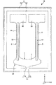
このような水晶振動片3は、基部4と、基部4の−Y’軸側の端から−Y’軸方向に延びている一対の振動腕5、6と、基部4の+Y’軸側に配置されており、X軸方向に延びている接続部72と、基部4と接続部72との間に位置し、基部4と接続部72とを連結している連結部71と、連結部71の両端部から−Y’軸方向に延びている一対の保持腕74、75と、を有している。
The
Such a
基部4は、XY’平面に広がりを有し、Z’軸方向に厚さを有する板状をなしている。そして、基部4の+Y’軸側の端から連結部71が+Y’軸方向に延出している。連結部71の+Y’軸側の端には、接続部72が接続されており、接続部72は、連結部71からX軸方向両側に延びている。また、連結部71の−X軸側の端部からは、保持腕74が−Y’軸方向に延出しており、+X軸側の端部からは、保持腕75が−Y’軸方向に延出している。保持腕74、75は、振動腕5、6の外側に位置しており、保持腕74、75の間に振動腕5、6が配置されている。なお、保持腕74、75の先端(−Y’軸側の端)は、振動腕5、6の先端(−Y’軸側の端)よりも+Y’軸側に位置している。
The
振動腕5、6は、X軸方向に並び、かつ、互いに平行となるように基部4の−Y’軸側の端から−Y’軸方向に延出している。これら振動腕5、6は、それぞれ、長手形状をなし、その基端(+Y’軸側の端)が固定端となり、先端(−Y’軸側の端)が自由端となる。また、振動腕5、6は、それぞれ、腕部51、61と、腕部51、61の先端に設けられ、腕部51、61よりもX軸方向に沿った長さが長い錘部としてのハンマーヘッド(広幅部)59、69と、を有している。
The vibrating
図3に示すように、腕部51は、XY’平面で構成された互いに表裏の関係にある1対の主面511、512と、Y’Z’平面で構成され、一対の主面511、512を接続する1対の側面513、514とを有している。また、腕部51には、主面511に開放する有底の溝52と、主面512に開口する有底の溝53とを有している。このように、振動腕5に溝52、53を形成することによって、熱弾性損失の低減を図ることができ、優れた振動特性を発揮することができる。溝52、53の長さは、特に限定されず、先端がハンマーヘッド59まで延びていてもよいし、基端が基部4まで延びていてもよい。このような構成とすることで、腕部51とハンマーヘッド(錘部)59の境界部および腕部51と基部4の境界部への応力集中が緩和され、衝撃が加わった際に発生する折れや欠けの虞が減少する。
As shown in FIG. 3, the
溝52、53の深さをt[μm]とし、振動腕5、6の厚さをT[μm]としたとき、深さtは、0.292≦t/T≦0.483なる関係を満足するのが好ましい。このような関係を満足することによって熱移動経路が長くなるから、後述する断熱的領域において、より効果的に、熱弾性損失の低減を図ることができる。また、深さtは、0.455≦t/T≦0.483なる関係を満足するのがさらに好ましい。このような関係を満足することによって、さらに熱移動経路が長くなることで熱弾性損失の低減を図ることができるので、Q値の向上とそれに伴うCI値の低減、さらには、屈曲変形する領域に電界をかけるための電極面積をより広くすることができることによるCI値の低減が実現される。
When the depth of the
溝52、53は、振動腕5の断面重心が、振動腕5の断面形状の中心と一致するように、振動腕5に対してX軸方向の位置を調整して形成されているのが好ましい。こうすることで、振動腕5の不要な振動(具体的には、面外方向成分を有する斜め振動)を低減するので、振動漏れを低減することができる。また、この場合、余計な振動をも駆動してしまうことを低減することになるので、相対的に駆動領域が増大してCI値を小さくすることができる。
The
このような腕部51の幅W1としては、特に限定されないが、16μm以上、300μm以下程度であるのが好ましい。幅W1が上記下限値未満であると、製造技術によっては、腕部51に溝52、532を形成することが困難となり、振動腕5を断熱的領域とすることができなくなる場合がある。一方、幅W1が上記上限値を超えると、厚みTの値によっては、腕部51の剛性が高くなり過ぎてしまい、腕部51の屈曲振動をスムーズに行うことができない場合がある。
The width W1 of the
次に、腕部51、62の先端に、それぞれ、形成された、ハンマーヘッド59、69について説明する。
ハンマーヘッド59、69は、振動素子2を所望の屈曲振動周波数で振動させた際に、互いに接触しない程度に、可能な限り近接して設けられ、水晶振動片3の小型化および高性能化を実現するために形成されるものである。これらハンマーヘッド59、69を設けることにより、振動腕5、6としての全長を短くすることができ、これに起因して、振動変位が小さくなるため、ハンマーヘッド59、69同士が衝突するのを的確に抑制または低減することができる。なお、このような効果は、比較的高い電力で振動腕5、6を振動させて、振動変位を大きくさせた際に、より顕著に得られることとなる。
Next, the hammer heads 59 and 69 formed at the tips of the
The hammer heads 59 and 69 are provided as close as possible to the extent that they do not come into contact with each other when the
さらに、振動腕5、6の長さを一定とした場合には、腕部51、61の先端部にハンマーヘッド59、69を設けることにより低下する屈曲振動の共振周波数を、腕部51、61の第2方向(X軸方向)に沿った長さ(幅)を拡げることによってハンマーヘッド59、69を設ける前と同一の共振周波数に維持すれば、屈曲振動時に腕部51、61で発生する熱が、腕部51、61の第2方向(X軸方向)に沿って流れるための経路が長くなるので、後述するように、断熱的領域において熱弾性損失を低減することによってQ値を向上させ、それと共にCI値を小さくすることができる。
Further, when the lengths of the vibrating
このようなハンマーヘッド59およびハンマーヘッド69は、本発明では、X軸方向に沿った、ハンマーヘッド59、69同士の離間距離W4(図1、4参照)が、0.033T(μm)≦W4≦0.33T(μm)の関係を満たすように設けられている。前記関係を満足することにより、後述するように、フォトリソグラフィ技術およびウエットエッチング技術を用いて、水晶振動片3を形成する際に、ハンマーヘッド59、69同士の離間距離W4と、振動腕5、6(ハンマーヘッド59、69)の厚さTとの関係が最適化され、その結果、超小型が実現された水晶振動片(水晶基板)3が形成されることとなる。
In the present invention, the
以下、上記関係式の算出方法について説明する。
ここで、ウエットエッチングにより、板厚T(μm)のZカット水晶板を貫通するのに要する時間をt1(分)、このZカット水晶板を実際に加工する時間をt2(分)、所定の係数をkとして、時間t2の間にZカット水晶板が±X軸方向にエッチングされる量(サイドエッチング量)の和をΔX(μm)とすると、ΔXは、ΔX=t2/t1×T×kで表すことができる。この式において、t1=t2とした場合には、ΔX=T×k…(式I)となる。
Hereinafter, a method for calculating the relational expression will be described.
Here, the time required for penetrating a Z-cut quartz plate having a plate thickness T (μm) by wet etching is t1 (minutes), and the time for actually processing this Z-cut quartz plate is t2 (minutes). If the coefficient is k and the sum of the amount (side etching amount) that the Z-cut quartz plate is etched in the ± X axis direction during time t2 is ΔX (μm), ΔX is ΔX = t2 / t1 × T × k can be represented. In this expression, when t1 = t2, ΔX = T × k (Expression I).
そこで、実際に厚さT=100(μm)のZカット水晶板が貫通するまで表裏の主面からウエットエッチングし、貫通した時点でウエットエッチングを終了する。その際のΔXを測定したところ、ΔXは1.63(μm)であった。この実測値を(式I)に代入することにより、k=0.0163と計算される。これは一方の主面からウエットエッチングした場合に換算すると、k=0.0326と計算される。 Therefore, wet etching is performed from the main surface of the front and back until the Z-cut quartz plate having a thickness T = 100 (μm) actually penetrates, and the wet etching is terminated at the time of penetration. When ΔX at that time was measured, ΔX was 1.63 (μm). By substituting this measured value into (Formula I), k = 0.0163 is calculated. This is calculated as k = 0.0326 in terms of wet etching from one main surface.
また、振動素子2を作成する場合には、振動腕5、6(ハンマーヘッド59、69)の断面形状が高い対称性をもつことによって振動漏れを抑圧するために、2≦t2/t1≦30…(式2)とするのが好ましい。この(式2)および(式1)に基づいて、表裏の主面からウエットエッチングした場合には、0.033T(μm)≦W4≦0.489T(μm)、一方の主面からウエットエッチングした場合には0.065T(μm)≦W4≦0.978T(μm)が得られる。
Further, when the
また、振動素子2を小型化する観点から、互いに表裏の関係にある第1の主面及び第2の主面からウエットエッチングすることによってΔXを小さくすることが好ましいため、上記関係式0.033T(μm)≦W4≦0.489T(μm)が導き出されるが、本発明では、上記関係式0.033T(μm)≦W4≦0.33T(μm)のように、その上限値をより小さい値に設定している。これにより、水晶振動片(音叉振動片)3の超小型が実現される。
Further, from the viewpoint of downsizing the
また、振動腕5、6(ハンマーヘッド59、69)の厚さTは、50μm≦T≦140μmであることが好ましい。これにより、小型でかつ、Q値の高い水晶振動片3を得ることができる。さらに、前記厚さTは、110μm≦T≦140μmであることがより好ましい。これにより、50μm≦T≦140μmとした場合と比較して、厚さTが厚い振動腕5、6となり、電気的に励振することの可能な面積が増大するので、小型でかつ、CI値の低い水晶振動片3を得ることができる。また、厚さTが厚いので、耐衝撃性に優れた水晶振動片3を得ることができる。
The thickness T of the vibrating
また、ハンマーヘッド59、69は、振動素子2では、振動腕5の全長(Y’軸方向の長さ)をとし、ハンマーヘッド59、69の全長(Y’軸方向の長さ)をHとしたとき、下記式(1)を満足することが好ましい。
ここで、ハンマーヘッド59は、腕部51の幅(X軸方向の長さ)に対して1.5倍以上の幅を有する領域とする。
In the
Here, the
![]()
![]()
以下、上記式(1)を満足することによる効果について、図5、図6に基づいて説明する。なお、ハンマーヘッド59、69は、同一の形状を有していることから、以下では、ハンマーヘッド59を代表に説明する。
図5には、ハンマーヘッド59の長さHと振動腕5の共振周波数との関係を指数化した曲線G1と、ハンマーヘッド59の長さHと振動腕5のQ値の関係を指数化した曲線G2とが示されている。なお、曲線G2で示すQ値は、熱弾性損失のみを考慮したものである。また、以下では、曲線G1の縦軸を「低周波化指数」とも言い、曲線G2の縦軸を「高Q値化指数」とも言う。
Hereinafter, the effect by satisfying said Formula (1) is demonstrated based on FIG. 5, FIG. Since the hammer heads 59 and 69 have the same shape, the
In FIG. 5, a curve G1 in which the relationship between the length H of the
また、曲線G1、G2を求めるためのシミュレーションは、1本の振動腕5を用いて行った。本シミュレーションで用いた振動腕5は、水晶Z板(回転角0°)で構成されている。また、振動腕5のサイズは、図6に示すように、全長Lが1210μm、厚さTが100μm、腕部51の幅W1が98μm、ハンマーヘッド59の幅W2が172μm、溝52、53の深さtが共に45μm、土手部511a、511b、512a、512bの幅W3がそれぞれ6.5μmである。このような振動腕5において、ハンマーヘッド59の長さHを変化させてシミュレーションを行った。なお、発明者らによって、振動腕5のサイズ(L、W1、W2、T、t1、t2、W3)を変更しても、下記に示すシミュレーション結果と同様の傾向となることが確認されている。
The simulation for obtaining the curves G1 and G2 was performed using one vibrating
図5では、曲線G1が規格化値(低周波化指数)=1となる点(H/L=0.51)で、最も振動腕5の共振周波数が低下していることを意味しており、曲線G2が規格化値(高Q値化指数)=1となる点(H/L=0.17)で、最も振動腕5のQ値が高いことを意味している。振動腕5の共振周波数が低い程、振動素子2を小型化することができるため、H/L=0.51(以下「条件1」とも言う)とすることで、最も振動素子2を小型化することができる。また、Q値を高くする程、熱弾性損失が小さく、優れた振動特性を発揮することができるため、H/L=0.17(以下「条件2」とも言う)とすることで、最も優れた振動特性を有する振動素子2とすることができる。
しかしながら、図5からも分かるように、H/L=0.51では、高Q値化指数が十分に高くなく、H/L=0.17では、低周波化指数が十分に高くない。したがって、条件1を満足するだけでは、優れた振動特性を得ることができず、反対に、条件2を満足するだけでは、振動素子2の小型化を十分に図ることができない。
In FIG. 5, the curve G1 is the point (H / L = 0.51) where the normalized value (low frequency index) = 1, which means that the resonance frequency of the vibrating
However, as can be seen from FIG. 5, the high Q index is not sufficiently high at H / L = 0.51, and the low frequency index is not sufficiently high at H / L = 0.17. Therefore, excellent vibration characteristics cannot be obtained only by satisfying the
そこで、振動素子2の小型化と振動特性の向上とを両立するための指数として「高性能化指数1」を設定し、高性能化指数1とH/Lとの関係を図7に示した。なお、[高性能化指数1]は、[低周波化指数]×[高Q値化指数]×[補正値]で表される。また、高性能化指数1は、その中で最大であった数値を1としたときの指数である。また、前記[補正値]は、1本の振動腕5で行ったシミュレーションを、2本の振動腕5、6を有する振動素子2へ適合させるための補正値である。そのため、補正値を用いることで、高性能化指数1をより振動素子2の物性に近づけることができる。
Therefore, “
ここで、高性能化指数1が0.8以上であれば、十分に、小型化と振動特性の向上とを両立させた振動素子2が得られる。そのため、振動素子2では、0.183≦H/L≦0.597なる関係を満足するようにハンマーヘッド59の長さHを設定している。すなわち、上記式(1)を満足するように振動素子2を構成している。また、この範囲の中でも、高性能化指数1が0.9以上となるように、0.238≦H/L≦0.531なる関係を満足することが好ましい。これにより、小型化と振動特性の向上とをさらに両立させた振動素子2が得られる。
Here, if the
さらに、ハンマーヘッド59、69は、振動素子2では、前述したのと同様に、振動腕5の全長(Y’軸方向の長さ)をLとし、ハンマーヘッド59の長さ(Y’軸方向の長さ)をHとしたとき、0.012<H/L<0.3なる関係を満足することが好ましく、0.046<H/L<0.223なる関係を満足しているのがより好ましい。このような関係を満足することによって、振動素子2のCI値が低く抑えられるため、振動損失が少なく、優れた振動特性を有する振動素子2となる。
Further, in the
なお、ハンマーヘッド59、69は、同一の形状を有していることから、以下では、ハンマーヘッド59を代表に説明する。
また、本実施形態では、「振動腕5の基端」を、側面514が基部4と接続されている箇所と、側面513が基部4と接続されている箇所を結んだ線分の、振動腕5の幅(X軸方向の長さ)中心に位置する箇所に設定している。
Since the hammer heads 59 and 69 have the same shape, the
In this embodiment, the “base end of the vibrating
また、振動腕5は、腕部51の幅(X軸方向の長さ)をW1とし、ハンマーヘッド59の幅(X軸方向の長さ)をW2としたとき、1.5≦W2/W1≦10.0なる関係を満足している。この関係を満足していれば、特に限定されないが、さらに、1.6≦W2/W1≦7.0なる関係を満足しているのが好ましい。このような関係を満足することにより、ハンマーヘッド59の幅を広く確保することができ、小型化や高性能化が成されると共に、ハンマーヘッド59の幅が広すぎることに起因する、屈曲振動時における振動腕5の捩れが増大することに起因する振動漏れが増大することを減少させることができる。そのため、ハンマーヘッド59の長さHが上述のように比較的短くても(Lの30%未満であっても)、ハンマーヘッド59による質量効果を十分に発揮することができる。したがって、1.5≦W2/W1≦10.0なる関係を満足することによって、振動腕5の全長Lが抑えされ、振動素子2の小型化を図ることができる。
このように、振動腕5では、1.2%<H/L<30.0%なる関係と、1.5≦W2/W1≦10.0なる関係とを満足することによって、これら2つの関係の相乗効果によって、小型化でCI値が十分に抑えられている振動素子2が得られる。
Further, in the vibrating
Thus, in the vibrating
なお、L≦2μm、好ましくは、L≦1μmとすることで、携帯型音楽機器やICカードのようなものに搭載する発振器に使用する、小型な振動素子を得ることができる。また、W1≦100μm、好ましくは、W1≦50μmとすることで、上記Lの範囲においても、低消費電力を実現する発振回路に使用する、低周波で共振する振動素子を得ることができる。また、断熱的領域であれば、水晶Z板でY’方向に振動腕が延び、X方向に屈曲振動する場合、W1≧12.8μmであることが好ましく、水晶Z板でX方向に振動腕が延び、Y’方向に屈曲振動する場合、W1≧14.4μmであることが好ましく、水晶X板でY’方向に振動腕が延び、Z’方向に屈曲振動する場合、W1≧15.9μmであることが好ましい。こうすることによって、確実に断熱的領域にすることができるので、溝の形成により熱弾性損失が減少してQ値が向上し、それと共に溝が形成されている領域で駆動することにより(電界効率が高く、駆動面積が稼げる)CI値が低くなる。 Note that when L ≦ 2 μm, preferably L ≦ 1 μm, a small vibration element used for an oscillator mounted on a portable music device or an IC card can be obtained. In addition, by setting W1 ≦ 100 μm, preferably W1 ≦ 50 μm, it is possible to obtain a resonator element that resonates at a low frequency and is used in an oscillation circuit that achieves low power consumption even in the range of L. In the adiabatic region, when the vibrating arm extends in the Y ′ direction and vibrates in the X direction on the quartz Z plate, W1 ≧ 12.8 μm is preferable, and the vibrating arm in the X direction on the quartz Z plate. W1 ≧ 14.4 μm, and when the vibrating arm extends in the Y ′ direction and bends and vibrates in the Z ′ direction, it is preferable that W1 ≧ 15.9 μm. It is preferable that In this way, since it can be surely made an adiabatic region, the thermoelastic loss is reduced by the formation of the groove, the Q value is improved, and by driving in the region where the groove is formed (electric field) (High efficiency and drive area can be obtained) The CI value becomes low.
次に、1.2%<H/L<30.0%なる関係と、1.5≦W2/W1≦10.0なる関係とを満足することによって、上記効果を発揮することができることをシミュレーション結果に基づいて証明する。なお、本シミュレーションは、1本の振動腕5を用いて行った。また、本シミュレーションで用いた振動腕5は、水晶Z板(回転角0°)で構成されている。また、振動腕5のサイズは、図6に示すように、全長Lが1210μm、厚さTが100μm、腕部51の幅W1が98μm、ハンマーヘッド59の幅W2が172μm、溝52、53の深さT1、T2が共に45μm、土手部511a、512aの幅W3がそれぞれ6.5μmである。このような振動腕5において、ハンマーヘッド59の長さHを変化させてシミュレーションを行った。なお、発見者によって、振動腕5のサイズ(L、W1、W2、T、T1、T2、W3)を変更しても、下記に示すシミュレーション結果と同様の傾向となることが確認されている。
Next, it is simulated that the above effect can be exhibited by satisfying the relationship 1.2% <H / L <30.0% and the relationship 1.5 ≦ W2 / W1 ≦ 10.0. Prove based on the results. This simulation was performed using one vibrating
下記の表1は、ハンマーヘッド59の長さHを変化させたときのCI値の変化を示す表である。なお、本シミュレーションでは、次のようにして、各サンプルのCI値を算出している。まず、有限要素法によって、熱弾性損失のみを考慮したQ値を求める。次に、Q値は、周波数依存性を有しているため、求められたQ値を32.768kHz時のQ値(F変換後Q値)に換算する。次に、F変換後Q値に基づいて、R1(CI値)を算出する。次に、CI値も周波数依存性を有しているため、求められたR1を32.768kHz時のR1に換算し、その逆数をとって「低R1指数」とした。低R1指数は、全てのシミュレーションの中で最大であった逆数を1としたときの指数である。
従って、低R1指数が1に近い程、CI値が小さいことを意味している。図8(a)に、横軸にハンマーヘッド占有率(H/L)、縦軸に低R1化指数をプロットしたグラフを示し、(b)に同図(a)の一部を拡大したグラフを示す。
なお、Q値をF変換後Q値へ換算する方法は、次の通りである。
Table 1 below shows a change in CI value when the length H of the
Therefore, the closer the low R1 index is to 1, the smaller the CI value. FIG. 8A shows a graph in which the horizontal axis represents the hammerhead occupancy (H / L), and the vertical axis plots the low R1 index, and FIG. 8B is a graph obtained by enlarging a part of FIG. Indicates.
The method of converting the Q value into the Q value after F conversion is as follows.
下記(式II)、(式III)を用いて次のような計算を行った。
f0=πk/(2ρCpa2)…(式II)
Q={ρCp/(Cα2H)}×[{1+(f/f0)2}/(f/f0)]…(式III)
ただし、(式II)、(式III)中のπは円周率、kは振動腕5の幅方向の熱電導率、ρは質量密度、Cpは熱容量、Cは振動腕5の長さ方向の伸縮の弾性スティフネス定数、αは振動腕5の長さ方向の熱膨張率、Hは絶対温度、fは固有周波数である。また、aは、振動腕5を図7に示すような平板形状として見做したきの幅(実効幅)である。なお、図7では、振動腕5に溝52、53が形成されていないが、この際のaの値を用いてもF変換後Q値への換算を行うことができる。
まず、シミュレーションで用いた振動腕5の固有周波数をF1とし、求められたQ値をQ1とし、(式II)、(式III)を用いて、f=F1、Q=Q1となるようなaの値を求める。次に、求められたaを用い、また、f=32.768kHzとし、後述する式(4)からQの値を算出する。このようにして得られたQ値がF変換後Q値となる。
The following calculations were performed using the following (formula II) and (formula III).
f 0 = πk / (2ρCpa 2 ) (Formula II)
Q = {ρCp / (Cα 2 H)} × [{1+ (f / f 0 ) 2 } / (f / f 0 )] (Formula III)
However, in (Formula II) and (Formula III), π is the circumferential ratio, k is the thermal conductivity in the width direction of the vibrating
First, the natural frequency of the vibrating

発明者らは、低R1化指数が0.87以上となる振動素子2を求めている。表1および図8のグラフから分かるように、1.2%<H/L<30.0%なる関係を満足するもの(SIM002〜SIM011)では低R1化指数が目標の0.87以上となっている。特に、4.6%<H/L<22.3%なる関係を満足するもの(SIM003〜SIM008)では低R1化指数が0.95を超えており、よりCI値が低くなっていることが分かる。以上のシミュレーション結果から、1.2%<H/L<30.0%なる関係を満足することにより、CI値が十分に抑えられている振動素子2が得られることが証明された。
The inventors are seeking a
さらに、図3に示すように、振動腕5には、一対の第1駆動用電極84と一対の第2駆動用電極85とが形成されている。第1駆動用電極84の一方は、溝52の側面に形成されており、他方は、溝53の側面に形成されている。また、第2駆動用電極85の一方は、側面513に形成されており、他方は、側面514に形成されている。
同様に、振動腕6にも、一対の第1駆動用電極84と一対の第2駆動用電極85とが形成されている。第1駆動用電極84の一方は、側面613に形成されており、他方は、側面614に形成されている。また、第2駆動用電極85の一方は、溝62の側面に形成されており、他方は、溝66の側面に形成されている。
Further, as shown in FIG. 3, the vibrating
Similarly, a pair of
各第1駆動用電極84は、図示しない配線によって、保持腕74まで引き出され、導電性接着材11を介して接続端子951と電気的に接続されている。同様に、各第2駆動用電極85は、図示しない配線によって、保持腕75まで引き出され、導電性接着材12を介して接続端子961と電気的に接続されている。
これら第1、第2駆動用電極84、85間に交番電圧を印加すると、振動腕5、6が互いに接近、離間を繰り返すようにX軸方向(面内方向)に所定の周波数で振動する。この振動モードは、一般的に「X逆相モード」と呼ばれており、以下では、この振動モードを「基本振動モード」とも言う。
Each
When an alternating voltage is applied between the first and
第1、第2駆動用電極84、85の構成材料としては、導電性を有していれば、特に限定されず、例えば、金(Au)、金合金、白金(Pt)、アルミニウム(Al)、アルミニウム合金、銀(Ag)、銀合金、クロム(Cr)、クロム合金、ニッケル(Ni)、ニッケル合金、銅(Cu)、モリブデン(Mo)、ニオブ(Nb)、タングステン(W)、鉄(Fe)、チタン(Ti)、コバルト(Co)、亜鉛(Zn)、ジルコニウム(Zr)等の金属材料、酸化インジウムスズ(ITO)等が挙げられる。
The constituent material of the first and
また、第1、第2駆動用電極84、85の具体的な構成としては、例えば、700Å以下のCr層上に700Å以下のAu層を形成した構成とすることができる。特に、CrやAuは、熱弾性損失が大きいので、Cr層、Au層は、好ましくは200Å以下とされる。また、絶縁破壊耐性を高くする場合には、Cr層、Au層は、好ましくは1000Å以上とされる。さらに、Niは、水晶の熱膨張係数に近いので、Cr層に替えてNi層を下地にすることで、電極に起因する熱応力を減少させ、長期信頼性(エージング特性)の良い振動素子を得ることができる。
以上、振動素子2の構成を説明した。上述したように、振動素子2の各振動腕5、6に溝52、53、62、63を形成することによって、熱弾性損失の低減を図ることができ、優れた振動特性を発揮することができる。以下、このことについて、振動腕5を例にして具体的に説明する。
As a specific configuration of the first and
The configuration of the
振動腕5は、前述したように、第1、第2駆動用電極84、85間に交番電圧を印加することにより面内方向に屈曲振動する。図9に示すように、この屈曲振動の際、腕部51の側面513が収縮すると側面514が伸張し、反対に、側面513が伸張すると側面514が収縮する。振動腕5がGough−Joule効果を発生しない(エネルギー弾性がエントロピー弾性に対して支配的な)場合、側面513、514のうち、収縮する面側の温度は上昇し、伸張する面側の温度は下降する。そのため、側面513と側面514との間、つまり腕部51の内部に温度差が発生する。この温度差から生じる熱伝導によって振動エネルギーの損失が発生し、これにより振動素子2のQ値が低下する。このようなQ値の低下に伴うエネルギーの損失を熱弾性損失とも言う。
As described above, the vibrating
振動素子2のような構成の屈曲振動モードで振動する振動素子において、振動腕5の屈曲振動周波数(機械的屈曲振動周波数)fが変化したとき、振動腕5の屈曲振動周波数が熱緩和周波数fmと一致するときにQ値が最小となる。この熱緩和周波数fmは、下記式(2)で求めることができる。ただし、ただし、式(2)中、πは円周率であり、eをネイピア数とすれば、τは温度差が熱伝導によりe−1倍になるのに要する緩和時間である)。
In the vibration element that vibrates in the bending vibration mode configured as the
![]()
![]()
また、平板構造(断面形状が矩形の構造)の熱緩和周波数をfm0とすれば、fm0は下記式(3)で求めることができる。なお、式(3)中、πは円周率、kは振動腕5の振動方向の熱伝導率、ρは振動腕5の質量密度、Cpは振動腕5の熱容量、aは振動腕5の振動方向の幅である。式(3)の熱伝導率k、質量密度ρ、熱容量Cpに振動腕5の材料そのもの(すなわち水晶)の定数を入力した場合、求まる熱緩和周波数fm0は、振動腕5に溝52、53を設けていない場合の値となる。
Further, if the thermal relaxation frequency of the flat plate structure (structure having a rectangular cross-sectional shape) is fm0, fm0 can be obtained by the following formula (3). In Equation (3), π is the circularity ratio, k is the thermal conductivity of the vibrating
振動腕5では、側面513、514の間に位置するように溝52、53が形成されている。そのため、振動腕5の屈曲振動時に生じる側面513、514の温度差を熱伝導により温度平衡させるための熱移動経路が溝52、53を迂回するように形成され、熱移動経路が側面513、514間の直線距離(最短距離)よりも長くなる。そのため、振動腕5に溝52、53を設けていない場合と比較して緩和時間τが長くなり、熱緩和周波数fmが低くなる。
In the vibrating
図10は、屈曲振動モードの振動素子のQ値のf/fm依存性を表すグラフである。同図において、点線で示されている曲線F1は、振動素子2のように振動腕に溝が形成されている場合を示し、実線で示されている曲線F2は、振動腕に溝が形成されていない場合を示している。同図に示すように、曲線F1、F2の形状は変わらないが、前述のような熱緩和周波数fmの低下に伴って、曲線F1が曲線F2に対して周波数低下方向へシフトする。したがって、振動素子2のように振動腕に溝が形成されている場合の熱緩和周波数をfm1とすれば、下記式(4)を満たすことにより、常に、振動腕に溝が形成されている振動素子のQ値が振動腕に溝が形成されていない振動素子のQ値に対して高くなる。
FIG. 10 is a graph showing the f / fm dependency of the Q value of the vibration element in the bending vibration mode. In the figure, a curved line F1 indicated by a dotted line indicates a case where a groove is formed in the vibrating arm like the vibrating
![]()
![]()
更に、下記式(5)の関係に限定すれば、より高いQ値を得ることができる。 Furthermore, if it is limited to the relationship of the following formula (5), a higher Q value can be obtained.
![]()
![]()
なお、図10において、f/fm<1の領域を等温的領域とも言い、この等温的領域ではf/fmが小さくなるにつれてQ値が高くなる。これは、振動腕の機械的周波数が低くなる(振動腕の振動が遅くなる)につれて前述のような振動腕内の温度差が生じ難くなるためである。したがって、f/fmを0(零)に限りなく近づけた際の極限では、等温準静操作となって、熱弾性損失は限りなく0(零)に接近する。一方、f/fm>1の領域を断熱的領域とも言い、この断熱的領域ではf/fmが大きくなるにつれてQ値が高くなる。これは、振動腕の機械的周波数が高くなるにつれて、各側面の温度上昇・温度効果の切り替わりが高速となり、前述のような熱伝導が生じる時間がなくなるためである。したがって、f/fmを限りなく大きくした際の極限では、断熱操作となって、熱弾性損失は限りなく0(零)に接近する。このことから、f/fm>1の関係を満たすとは、f/fmが断熱的領域にあるとも言い換えることができる。 In FIG. 10, a region where f / fm <1 is also referred to as an isothermal region, and in this isothermal region, the Q value increases as f / fm decreases. This is because the temperature difference in the vibrating arm as described above is less likely to occur as the mechanical frequency of the vibrating arm becomes lower (the vibration of the vibrating arm becomes slower). Therefore, in the limit when f / fm is brought close to 0 (zero) as much as possible, the operation becomes an isothermal quasi-static operation, and the thermoelastic loss approaches 0 (zero) as much as possible. On the other hand, a region where f / fm> 1 is also referred to as an adiabatic region. In this adiabatic region, the Q value increases as f / fm increases. This is because as the mechanical frequency of the vibrating arm increases, the temperature rise and switching of the temperature effect on each side surface become faster, and there is no time for heat conduction as described above. Therefore, in the limit when f / fm is increased as much as possible, the operation becomes adiabatic, and the thermoelastic loss approaches 0 (zero) as much as possible. From this, satisfying the relationship of f / fm> 1 can be rephrased as f / fm being in the adiabatic region.
ここで、第1、第2駆動用電極84、85の構成材料(金属材料)は、振動腕5、6の構成材料である水晶と比較して熱伝導率が高いため、振動腕5では、第1駆動用電極84を介する熱伝導が積極的に行われ、振動腕6では、第2駆動用電極85を介する熱伝導が積極的に行われる。このような第1、第2駆動用電極84、85を介する熱伝導が積極的に行われると、緩和時間τが短くなってしまう。そこで、振動腕5では、溝52、53の底面にて第1駆動用電極84を側面513側と側面514側とに分割し、振動腕6では溝62、63の底面にて第2駆動用電極85を側面613側と側面614側とに分割し、上記のような熱伝導を低減することが好ましい。その結果、断熱的領域においては、緩和時間τが短くなるのを防ぎ、より高いQ値を有する振動素子2が得られる。
以上、熱弾性損失について説明した。
Here, since the constituent material (metal material) of the first and
The thermoelastic loss has been described above.
振動素子2は、式(5)を満足し、加えて、振動腕5、6に所定の形状の溝52、53、62、63を形成することにより、従来の振動素子よりも高いQ値が得られるように構成されているのが好ましい。以下、振動腕5、6に形成された溝52、53、62、63の構成について具体的に説明する。なお、振動腕5、6は、互いに同様の構成であるため、以下では、振動腕5に形成された溝52、53について代表して説明し、振動腕6に形成された溝62、63については、その説明を省略する。
The
図3に示すように、振動腕5の厚さ(Z’軸方向の長さ)をTとし、各溝52、53の最大深さをtとし、主面511、512の溝52、53のX軸方向両側に位置する土手部(振動腕5の長手方向に直交する幅方向に沿って溝52を挟んで並んでいる主面)511a、511b、512a、512bの幅をW3[μm]としたとき、振動素子2は、下記式(6)、(7)を共に満足していることが好ましい。
As shown in FIG. 3, the thickness (length in the Z′-axis direction) of the vibrating
![]()
![]()
腕部51の少なくとも一部に、これら式(6)、(7)を共に満足する領域が存在することにより、従来よりも優れた振動特性を発揮する振動素子2を得ることができる。なお、式(6)、(7)を共に満足する領域は、腕部51の長手方向の一部に存在していればよいが、腕部51の基端部を含んで存在していることが好ましい。基端部は、腕部51の中でも大きく屈曲変形する部分であり、振動腕5の全体の振動特性に影響を与えやすい部位である。そのため、前記領域を少なくとも基端部に存在させることにより、より確実かつ効果的に、従来よりも優れた振動特性を発揮する振動素子2を得ることができる。また、言い換えれば、前記領域を少なくとも振動腕5の屈曲変形量が最大となる部位に存在させることにより、より確実かつ効果的に、従来品よりも優れた振動特性を発揮する振動素子2を得ることができる。
When at least a part of the
振動素子2では、腕部51がその両端部を除くほぼ全域でほぼ同一の幅および厚さとなるように構成されており、加えて、溝52、53がその両端部を除くほぼ全域でほぼ同一の幅および深さとなっている。そのため、振動素子2では、前記領域を腕部51の長手方向に長く存在させることができる。したがって、振動素子2は、上述の効果をより顕著に発揮することができる。具体的には、前記領域は、基端部を含めた振動腕5の全長(Y’軸方向の長さ)に対して3分の1の部分に存在していることが好ましい。こうすることによって、より確実かつ効果的に、従来品よりも優れた振動特性を発揮する振動素子2を得ることができる。
In the
以下、発明者が行ったシミュレーション結果に基づいて、このことを証明する。なお、以下では、Zカット水晶板をパターニングしてなり、屈曲振動周波数(機械的屈曲振動周波数)f=32.768kHzの振動素子を用いたシミュレーションを代表して用いるが、発明者らによって、屈曲振動周波数fが32.768kHz±1kHzの範囲では、下記に示すシミュレーション結果とほとんど差がないことが確認されている。 In the following, this will be proved based on the results of simulation performed by the inventors. Hereinafter, a Z-cut quartz plate is patterned, and a simulation using a vibration element with a bending vibration frequency (mechanical bending vibration frequency) f = 32.768 kHz is used as a representative. When the vibration frequency f is in the range of 32.768 kHz ± 1 kHz, it is confirmed that there is almost no difference from the simulation results shown below.
本シミュレーションでは、ウエットエッチングによって水晶基板をパターニングした水晶振動片を用いている。したがって、溝52、53は、図11に示すように、水晶の結晶面が現れた形状となっている。具体的には、−X軸方向のエッチングレートが+X軸方向のエッチングレートよりも低いため、−X軸方向の側面が比較的なだらかな傾斜となり、+X軸方向の側面が垂直に近い傾斜となる。なお、図11は、図3と同じ断面を図示している。
In this simulation, a crystal vibrating piece obtained by patterning a crystal substrate by wet etching is used. Therefore, as shown in FIG. 11, the
また、本シミュレーションで用いた振動腕5のサイズは、長さが1000μm、厚さが120μm、幅が80μmである。なお、発明者らによって、長さ、厚さ、幅を変更しても、下記に示すシミュレーション結果と同様の傾向となることが確認されている。また、本シミュレーションには、第1、第2駆動用電極84、85が形成されていない振動腕5を用いた。
The size of the vibrating
図12は、t/Tを、0.208、0.292、0.375、0.458、0.483としたときの、土手部511a、511b、512a、512bの幅W3とQ値との関係を示すグラフである。なお、Q値は、周波数依存性を有しているため、本シミュレーションでは、t/Tの各条件にて求められたQ値を32.768kHz時のQ値(F変換後Q値)に換算し、その逆数をとって「高性能化指数2」とした。高性能化指数2は、t/Tの各条件にて、その中で最大であった逆数を1としたときの指数である。したがって、高性能化指数2が1に近い程、Q値が高いことを意味している。
FIG. 12 shows the relationship between the width W3 and the Q value of the
なお、Q値をF変換後Q値へ換算する方法は、次の通りである。
下記式(8)、(9)を用いて次のような計算を行った。ただし、式(8)、(9)中の、πは円周率、kは振動腕5の幅方向の熱電導率、ρは質量密度、Cpは熱容量、Cは振動腕5の長さ方向の伸縮の弾性スティフネス定数、αは振動腕5の長さ方向の熱膨張率、Hは絶対温度、fは固有周波数である。また、aは、振動腕5を図13に示すような平板形状として見做したきの幅(実効幅)である。なお、図13では、振動腕5に溝52、53が形成されていないが、この際のaの値を用いてもF変換後Q値への換算を行うことができる。
The method of converting the Q value into the Q value after F conversion is as follows.
The following calculations were performed using the following formulas (8) and (9). In equations (8) and (9), π is the circularity ratio, k is the thermal conductivity in the width direction of the vibrating
まず、シミュレーションで用いた振動腕5の固有周波数をF1とし、求められたQ値をQ1とし、式(8)、(9)を用いて、f=F1、Q=Q1となるようなaの値を求める。次に、求められたaを用い、また、f=32.768kHzとし、式(9)からQの値を算出する。このようにして得られたQ値がF変換後Q値となる。
ここで、高性能化指数2が0.8以上であれば、十分に、Q値の高い(優れた振動特性を有する)振動素子2が得られ、高性能化指数2が0.9以上であれば、さらに、Q値の高い振動素子2が得られる。そこで、図14に、t/T=0.375の場合の高性能化指数=0.8となる点A1、A2と、t/T=0.458の場合の高性能化指数=0.8となる点B1、B2と、t/T=0.48の場合の高性能化指数=0.8となる点C1、C2とをプロットしたグラフを示す。各条件の幅W3が小さい方の点A1、B1、C1を結ぶ2次式(近似式)は、下記式(10)で示され、各条件の幅W3が大きい方の点A2、B2、C2を結ぶ2次式(近似式)は、下記式(11)で示される。ただし、単位は、[μm]である。
First, the natural frequency of the vibrating
Here, if the
![]()
![]()
![]()
![]()
したがって、式(10)を下限、式(11)を上限とする幅W3を有していれは、すなわち、上記式(6)、(7)を満足すれば、優れた振動特性を有する振動素子2を得ることができる。
また、図15に、t/T=0.292の場合の高性能化指数=0.9となる点A3、A4と、t/T=0.375の場合の高性能化指数=0.9となる点B3、B4と、t/T=0.48の場合の高性能化指数=0.9となる点C3、C4とをプロットしたグラフを示す。各条件の幅W3が小さい方の点A3、B3、C3を結ぶ2次式(近似式)は、下記式(12)で示され、各条件の幅W3が大きい方の点A4、B4、C4を結ぶ2次式(近似式)は、下記式(13)で示される。ただし、単位は、[μm]である。
Accordingly, if the width W3 has the lower limit of the formula (10) and the upper limit of the formula (11), that is, if the above formulas (6) and (7) are satisfied, the vibration element having
Further, FIG. 15 shows points A3 and A4 where the high performance index is 0.9 when t / T = 0.292, and the high performance index when the t / T = 0.375 is 0.9. The graph which plotted points B3 and B4 which become and points C3 and C4 at which the high performance index in the case of t / T = 0.48 = 0.9 is shown. A quadratic expression (approximate expression) connecting points A3, B3, and C3 having a smaller width W3 under each condition is expressed by the following expression (12), and points A4, B4, and C4 having a larger width W3 under each condition. A quadratic expression (approximate expression) that connects is expressed by the following expression (13). However, the unit is [μm].
![]()
![]()
![]()
![]()
したがって、下記式(14)、(15)を共に満足することによって、さらに優れた振動特性を有する振動素子2を得ることができる。ただし、単位は、[μm]である。
Therefore, by satisfying both the following formulas (14) and (15), it is possible to obtain the
![]()
![]()
また、図16に、t/T=0.292の場合の高性能化指数=1となる点A5と、t/T=0.375の場合の高性能化指数=1となる点B5と、t/T=0.48の場合の高性能化指数=1となる点C5とをプロットしたグラフを示す。点A5、B5、C5を結ぶ2次式(近似式)は、下記式(16)で示される。ただし、単位は、[μm]である。 FIG. 16 shows a point A5 where the high performance index = 1 when t / T = 0.292, a point B5 where the high performance index = 1 when t / T = 0.375, The graph which plotted the point C5 used as the high performance index | exponent = 1 in the case of t / T = 0.48 is shown. A quadratic expression (approximate expression) connecting the points A5, B5, and C5 is represented by the following expression (16). However, the unit is [μm].
![]()
![]()
したがって、下記式(17)、(18)を共に満足することによって、より優れた振動特性を有する振動素子2を得ることができる。
Therefore, the
![]()
![]()
![]()
![]()
さらに、振動素子2では、fm=πk/(2ρCpa2)としたときにf/fm>1の範囲を満足し、加えて、振動腕5、6に所定の形状の溝52、53、62、63を形成することにより、従来の振動素子よりも高いQ値が得られるように構成されていることが好ましい。
Further, in the
以下、振動腕5、6に形成された溝52、53、62、63の構成について具体的に説明する。なお、振動腕5、6は、互いに同様の構成であるため、以下では、振動腕5に形成された溝52、53について代表して説明し、振動腕6に形成された溝62、63については、その説明を省略する。
図3に示すように、振動素子2では、主面511の溝52のX軸方向両側に位置する土手部(振動腕5の長手方向に直交する幅方向に沿って溝52を挟んで並んでいる主面)511a、511bの幅(X軸方向の長さ)が互いにほぼ等しく、その土手部511a、511bの幅をW3[μm]とし、振動腕5の厚さ(Z’軸方向の長さ)をTとし、溝52、53の最大深さtの合計をtaとし、ta/Tをηとしたとき、下記式(A)で示す関係を満足している。
Hereinafter, the configuration of the
As shown in FIG. 3, in the
4.236×10×η2−8.473×10×η+4.414×10≦W3≦−3.367×10×η2+7.112×10×η−2.352×10 ・・・・(A)
但し、0.75≦η<1.00
なお、主面512の溝53のX軸方向両側に位置する土手部(部位)512a、512bの幅についても同様の関係を満足している。
4.236 × 10 × η 2 −8.473 × 10 × η + 4.414 × 10 ≦ W3 ≦ −3.367 × 10 × η 2 + 7.112 × 10 × η-2.352 × 10 A)
However, 0.75 ≦ η <1.00
The same relationship is satisfied for the widths of the bank portions (parts) 512a and 512b located on both sides of the
振動腕5の少なくとも一部に、式(A)を満足する領域Saが存在することにより、従来よりも優れた振動特性を発揮する振動素子2を得ることができる。なお、式(A)を満足する領域Saは、振動腕5の長手方向の一部に存在していればよいが、振動腕5の基端部を含んで存在していることが好ましい。基端部は、振動腕5の中でも大きく屈曲変形する部分であり、振動腕5の全体の振動特性に影響を与えやすい部位である。そのため、領域Saを少なくとも基端部に存在させることにより、より確実かつ効果的に、従来よりも優れた振動特性を発揮する振動素子2を得ることができる。また、言い換えれば、領域Saを少なくとも振動腕5の屈曲変形量が最大となる部位に存在させることにより、より確実かつ効果的に、従来品よりも優れた振動特性を発揮する振動素子2を得ることができる。より具体的には、領域Saは、腕部51の基端部から先端部へ向かって、腕部51の長さに対して33%の長さの領域を含んで存在していることが好ましいと言える。
Since the region Sa that satisfies the formula (A) is present in at least a part of the vibrating
図1に示すように、本実施形態の振動素子2では、腕部51がその両端部を除くほぼ全域(領域S1)にてほぼ同一の幅および厚さとなるように構成されており、加えて、溝52、53が全域(領域S2)にてほぼ同一の幅および深さとなるように形成されている。振動素子2では、このような領域S1、S2が重なり合う領域が領域Saを構成しているため、領域Saを振動腕5の長手方向に長く存在させることができる。したがって、上述した効果がより顕著となる。
なお、前記式(A)は、熱弾性損失のみを考慮したQ値をQTEDとし、そのQTEDが所定値よりも高くなる条件である。
As shown in FIG. 1, in the
The equation (A) is a condition in which the Q value considering only the thermoelastic loss is Q TED and the Q TED is higher than a predetermined value.
以下、説明を続けるが、QTEDを規格化してその説明を行う。QTEDの規格化は、ηが限りなく1に近いときに予想されるQTEDを1として行う。すなわち、ηが限りなく1に近いときに予想されるQTEDをQTED(η=1)とし、規格化される前のQTEDをQTEDbとし、規格化されたQTEDをQTEDaとしたとき、そのQTEDaは、QTEDb/QTED(η=1)で表される。 Hereinafter, the description will be continued, but Q TED will be standardized and described. Standardization of Q TED performs Q TED expected when η is infinitely close to 1 as one. That is, Q TED expected when η is infinitely close to 1 is Q TED (η = 1), Q TED before standardization is Q TED b, and standardized Q TED is Q TED a Q TED a is expressed by Q TED b / Q TED (η = 1).
まず、前記式(A)は、QTEDa≧0.65となる条件である。そして、QTEDa≧0.70、QTEDa≧0.75、QTEDa≧0.80、QTEDa≧0.85となる条件は、それぞれ、下記の通りである。
(QTEDa≧0.70)
QTEDa≧0.70となる条件は、下記式(B)で示す関係を満足することである。
5.459×10×η2−1.110×10²×η+5.859×10≦W3≦−4.500×10×η2+9.490×10×η−3.698×10 [μm] ・・・・(B)
First, the formula (A) is a condition that satisfies Q TED a ≧ 0.65. The conditions for Q TED a ≧ 0.70, Q TED a ≧ 0.75, Q TED a ≧ 0.80, and Q TED a ≧ 0.85 are as follows.
(Q TED a ≧ 0.70)
The condition for Q TED a ≧ 0.70 is to satisfy the relationship represented by the following formula (B).
5.459 × 10 × η 2 −1.110 × 10 2 × η + 5.859 × 10 ≦ W3 ≦ −4.500 × 10 × η 2 + 9.490 × 10 × η−3.698 × 10 [μm] ... (B)
但し、0.80≦η<1.00
(QTEDa≧0.75)
QTEDa≧0.75となる条件は、下記式(C)で示す関係を満足することである。
6.675×10×η2−1.380×10²×η+7.392×10≦W3≦−5.805×10×η2+1.228×10²×η−5.267×10 [μm] ・・・・(C)
However, 0.80 ≦ η <1.00
(Q TED a ≧ 0.75)
The condition for Q TED a ≧ 0.75 is to satisfy the relationship represented by the following formula (C).
6.675 × 10 × η 2 −1.380 × 10 2 × η + 7.392 × 10 ≦ W3 ≦ −5.805 × 10 × η 2 + 1.228 × 10 2 × η−5.267 × 10 [μm] .... (C)
但し、0.85≦η<1.00
(QTEDa≧0.80)
QTEDa≧0.80となる条件は、下記式(D)で示す関係を満足することである。
7.752×10×η2−1.634×10²×η+8.903×10≦W3≦−6.993×10×η2+1.496×10²×η−6.844×10 [μm] ・・・・(D)
However, 0.85 ≦ η <1.00
(Q TED a ≧ 0.80)
The condition for Q TED a ≧ 0.80 is to satisfy the relationship represented by the following formula (D).
7.752 × 10 × η 2 −1.634 × 10 2 × η + 8.903 × 10 ≦ W3 ≦ −6.993 × 10 × η 2 + 1.696 × 10 2 × η−6.844 × 10 [μm] .... (D)
但し、0.90≦η<1.00
(QTEDa≧0.85)
QTEDa≧0.85となる条件は、下記式(E)で示す関係を満足することである。
−1.847×10×η+2.217×10≦W3≦1.189×10×η−8.433 [μm] ・・・・(E)
但し、0.95≦η<1.00
However, 0.90 ≦ η <1.00
(Q TED a ≧ 0.85)
The condition for Q TED a ≧ 0.85 is to satisfy the relationship represented by the following formula (E).
−1.847 × 10 × η + 2.217 × 10 ≦ W3 ≦ 1.189 × 10 × η−8.433 [μm] (E)
However, 0.95 ≦ η <1.00
(QTEDa≧0.90)
QTEDa≧0.90となる条件は、下記式(F)で示す関係を満足することである。
−3.300×10×η+3.730×10[μm]≦W[μm]≦3.302×10×η−2.333×10[μm] ・・・・(F)
但し、0.95≦η<1.00
(Q TED a ≧ 0.90)
The condition for Q TED a ≧ 0.90 is to satisfy the relationship represented by the following formula (F).
-3.300 × 10 × η + 3.730 × 10 [μm] ≦ W [μm] ≦ 3.32 × 10 × η-2.333 × 10 [μm] (F)
However, 0.95 ≦ η <1.00
以下、発明者が行ったシミュレーションにより解析した結果に基づいて、これらの条件を実証する。なお、以下では、Zカット水晶板をパターニングしてなり、屈曲振動周波数(機械的屈曲振動周波数)f=32.768kHzの振動素子2を用いたシミュレーションを代表して用いるが、発見者によって、屈曲振動周波数fが32.768kHz±1kHzの範囲では、下記に示すシミュレーションによる解析結果とほとんど差がないことが確認されている。
Hereinafter, these conditions will be verified based on the results of analysis by simulation performed by the inventors. In the following, a Z-cut quartz plate is patterned and a simulation using the
また、本シミュレーションでは、ウエットエッチングによって水晶基板をパターニングした水晶振動片3を備える振動素子2を用いている。したがって、溝52、53は、図11に示すように、水晶の結晶面が現れた形状となっている。なお、図11では、図1中のB−B線断面に相当する断面を示している。−X軸方向のエッチングレートが+X軸方向のエッチングレートよりも低いため、−X軸方向の側面が比較的なだらかな傾斜となり、+X軸方向の側面が垂直に近い傾斜となる。
In this simulation, the
また、本シミュレーションで用いた振動素子2の水晶振動片3のサイズは、長さが1160μm、幅が520μm、厚さ、すなわち、振動腕5、6のそれぞれの厚さTが120μmである。なお、発見者によって、長さ、幅、厚さを変更しても、下記に示すシミュレーション結果とほとんど差がないことが確認されている。また、本シミュレーションには、第1、第2駆動用電極84、85が形成されていない振動素子2を用いた。
The size of the
図19は、ηを、それぞれ、0.40、0.60、0.70、0.75、0.80、0.85、0.90、0.95、0.99としたときの、土手部511a、511b、512a、512bの幅W3とQTEDaとの関係を示すグラフである。また、振動素子2にて達成すべきQTEDaの下限値Qminを0.65とし、線分L1で示している。QTEDaをこの値以上とすることにより、優れた振動特性を発揮することができる。
FIG. 19 shows a bank when η is 0.40, 0.60, 0.70, 0.75, 0.80, 0.85, 0.90, 0.95, and 0.99, respectively.
図19から、ηが0.75、0.80、0.85、0.90、0.95、0.99のときに、QTEDaが0.65以上の領域が存在することが読み取れる。このことから、前述したように、QTEDa≧0.65とするには、「0.75≦η<1.00」なる関係を満足する必要があることが読み取れる。
また、図20は、図19において各グラフがQTEDa=0.65とクロスする各点をプロットして得られたグラフであり、QTEDa=0.65(Qmin)である場合におけるηとW3の関係を示すグラフである。
From FIG. 19, it can be seen that when η is 0.75, 0.80, 0.85, 0.90, 0.95, and 0.99, there is a region where Q TED a is 0.65 or more. From this, as described above, it can be read that it is necessary to satisfy the relationship of “0.75 ≦ η <1.00” in order to satisfy Q TED a ≧ 0.65.
FIG. 20 is a graph obtained by plotting each point where each graph crosses Q TED a = 0.65 in FIG. 19, and in the case where Q TED a = 0.65 (Q min ). It is a graph which shows the relationship between (eta) and W3.
この場合、W3の下限値を示すグラフは、下記式(G)で示される。
W3[μm]=4.236×10×η2−8.473×10×η+4.414×10[μm] ・・・(G)
また、W3の上限値を示すグラフは、下記式(H)で示される。
W3[μm]=−3.367×10×η2+7.112×10×η−2.352×10[μm] ・・・(H)
In this case, the graph indicating the lower limit value of W3 is represented by the following formula (G).
W3 [μm] = 4.236 × 10 × η 2 −8.473 × 10 × η + 4.414 × 10 [μm] (G)
Moreover, the graph which shows the upper limit of W3 is shown by a following formula (H).
W3 [μm] = − 3.367 × 10 × η 2 + 7.112 × 10 × η−2.352 × 10 [μm] (H)
したがって、図20から、前記式(A)で示す関係を満たすことにより、0.65以上のQTEDaを有する振動素子2が得られることが読み取れる。以上より、式(A)を満足することにより、0.65以上の高いQTEDaが得られ、振動特性に優れた振動素子2となることが証明される。
同様に、図19から、ηが0.80、0.85、0.90、0.95、0.99のときに、QTEDaが0.70以上の領域が存在することが読み取れる。このことから、前述したように、QTEDa≧0.70とするには、「0.80≦η<1.00」なる関係を満足する必要があることが読み取れる。
また、図21は、図19において各グラフがQTEDa=0.70とクロスする各点をプロットして得られたグラフであり、QTEDa=0.70(Qmin)である場合におけるηとW3の関係を示すグラフである。
Therefore, it can be seen from FIG. 20 that the
Similarly, it can be seen from FIG. 19 that when η is 0.80, 0.85, 0.90, 0.95, and 0.99, there is a region where Q TED a is 0.70 or more. From this, as described above, it can be read that in order to satisfy Q TED a ≧ 0.70, it is necessary to satisfy the relationship of “0.80 ≦ η <1.00”.
FIG. 21 is a graph obtained by plotting each point where each graph crosses Q TED a = 0.70 in FIG. 19, and in the case where Q TED a = 0.70 (Q min ). It is a graph which shows the relationship between (eta) and W3.
この場合、W3の下限値を示すグラフは、下記式(J)で示される。
W3[μm]=5.459×10×η2−1.110×10²×η+5.859×10[μm] ・・・・(J)
また、W3の上限値を示すグラフは、下記式(K)で示される。
W3[μm]=−4.500×10×η2+9.490×10×η−3.698×10[μm] ・・・・(K)
In this case, the graph indicating the lower limit value of W3 is represented by the following formula (J).
W3 [μm] = 5.459 × 10 × η 2 −1.110 × 10 2 × η + 5.859 × 10 [μm] (J)
Moreover, the graph which shows the upper limit of W3 is shown by a following formula (K).
W3 [μm] = − 4.500 × 10 × η 2 + 9.490 × 10 × η−3.698 × 10 [μm] (K)
したがって、図21から、前記式(B)で示す関係を満たすことにより、0.70以上のQTEDaを有する振動素子2が得られることが読み取れる。以上より、式(B)を満足することにより、0.70以上の高いQTEDaが得られ、振動特性に優れた振動素子2となることが証明される。
同様に、図19から、ηが0.85、0.90、0.95、0.99のときに、QTEDaが0.75以上の領域が存在することが読み取れる。このことから、前述したように、QTEDa≧0.75とするには、「0.85≦η<1.00」なる関係を満足する必要があることが読み取れる。
また、図22は、図19において各グラフがQTEDa=0.75とクロスする各点をプロットして得られたグラフであり、QTEDa=0.75(Qmin)である場合におけるηとW3の関係を示すグラフである。
Therefore, it can be read from FIG. 21 that the
Similarly, it can be seen from FIG. 19 that when η is 0.85, 0.90, 0.95, and 0.99, there is a region where Q TED a is 0.75 or more. From this, as described above, it can be read that in order to satisfy Q TED a ≧ 0.75, it is necessary to satisfy the relationship of “0.85 ≦ η <1.00”.
FIG. 22 is a graph obtained by plotting each point at which each graph crosses Q TED a = 0.75 in FIG. 19, and in the case where Q TED a = 0.75 (Q min ). It is a graph which shows the relationship between (eta) and W3.
この場合、W3の下限値を示すグラフは、下記式(L)で示される。
W3[μm]=6.675×10×η2−1.380×10²×η+7.392×10[μm] ・・・・(L)
また、W3の上限値を示すグラフは、下記式(M)で示される。
W3[μm]=−5.805×10×η2+1.228×10²×η−5.267×10[μm] ・・・・(M)
In this case, the graph indicating the lower limit value of W3 is represented by the following formula (L).
W3 [μm] = 6.675 × 10 × η 2 −1.380 × 10 2 × η + 7.392 × 10 [μm] (L)
Moreover, the graph which shows the upper limit of W3 is shown by a following formula (M).
W3 [μm] = − 5.805 × 10 × η 2 + 1.228 × 10 2 × η−5.267 × 10 [μm] (M)
したがって、図22から、前記式(C)で示す関係を満たすことにより、0.75以上のQTEDaを有する振動素子2が得られることが読み取れる。以上より、式(C)を満足することにより、0.75以上の高いQTEDaが得られ、振動特性に優れた振動素子2となることが証明される。
同様に、図19から、ηが0.90、0.95、0.99のときに、QTEDaが0.80以上の領域が存在することが読み取れる。このことから、前述したように、QTEDa≧0.80とするには、「0.90≦η<1.00」なる関係を満足する必要があることが読み取れる。
また、図23は、図19において各グラフがQTEDa=0.80とクロスする各点をプロットして得られたグラフであり、QTEDa=0.80(Qmin)である場合におけるηとW3の関係を示すグラフである。
この場合、W3の下限値を示すグラフは、下記式(N)で示される。
Therefore, it can be read from FIG. 22 that the
Similarly, it can be seen from FIG. 19 that there is a region where Q TED a is 0.80 or more when η is 0.90, 0.95, and 0.99. From this, as described above, it can be read that in order to satisfy Q TED a ≧ 0.80, it is necessary to satisfy the relationship “0.90 ≦ η <1.00”.
FIG. 23 is a graph obtained by plotting each point where each graph crosses Q TED a = 0.80 in FIG. 19, and in the case where Q TED a = 0.80 (Q min ). It is a graph which shows the relationship between (eta) and W3.
In this case, the graph indicating the lower limit value of W3 is represented by the following formula (N).
W3[μm]=7.752×10×η2−1.634×10²×η+8.903×10[μm] ・・・・(N)
また、W3の上限値を示すグラフは、下記式(P)で示される。
W3[μm]=−6.993×10×η2+1.496×10²×η−6.844×10[μm] ・・・・(P)
W3 [μm] = 7.752 × 10 × η 2 −1.634 × 10 2 × η + 8.903 × 10 [μm] (N)
Moreover, the graph which shows the upper limit of W3 is shown by a following formula (P).
W3 [μm] = − 6.993 × 10 × η 2 + 1.496 × 10 2 × η−6.844 × 10 [μm] (P)
したがって、図23から、前記式(D)で示す関係を満たすことにより、0.80以上のQTEDaを有する振動素子2が得られることが読み取れる。以上より、式(D)を満足することにより、0.80以上の高いQTEDaが得られ、振動特性に優れた振動素子2となることが証明される。
同様に、図19から、ηが0.95、0.99のときに、QTEDaが0.85以上の領域が存在することが読み取れる。このことから、前述したように、QTEDa≧0.85とするには、「0.95≦η<1.00」なる関係を満足する必要があることが読み取れる。
また、図24は、図19において各グラフがQTEDa=0.85とクロスする各点をプロットして得られたグラフであり、QTEDa=0.85(Qmin)である場合におけるηとW3の関係を示すグラフである。
Therefore, it can be seen from FIG. 23 that the
Similarly, it can be seen from FIG. 19 that there is a region where Q TED a is 0.85 or more when η is 0.95 and 0.99. From this, as described above, it can be read that it is necessary to satisfy the relationship of “0.95 ≦ η <1.00” in order to satisfy Q TED a ≧ 0.85.
FIG. 24 is a graph obtained by plotting each point where each graph crosses Q TED a = 0.85 in FIG. 19, and in the case where Q TED a = 0.85 (Q min ). It is a graph which shows the relationship between (eta) and W3.
この場合、W3の下限値を示すグラフは、下記式(Q)で示される。
W3[μm]=−1.847×10×η+2.217×10[μm] ・・・・(Q)
また、W3の上限値を示すグラフは、下記式(R)で示される。
W3[μm]=1.189×10×η−8.433[μm] ・・・・(R)
したがって、図24から、前記式(E)で示す関係を満たすことにより、0.85以上のQTEDaを有する振動素子2が得られることが読み取れる。以上より、式(E)を満足することにより、0.85以上の高いQTEDaが得られ、振動特性に優れた振動素子2となることが証明される。
In this case, the graph indicating the lower limit value of W3 is represented by the following formula (Q).
W3 [μm] = − 1.847 × 10 × η + 2.217 × 10 [μm] (Q)
Moreover, the graph which shows the upper limit of W3 is shown by a following formula (R).
W3 [μm] = 1.189 × 10 × η−8.433 [μm] (R)
Therefore, it can be seen from FIG. 24 that the
なお、図25は、図19において各グラフがQTEDa=0.90とクロスする各点をプロットして得られたグラフであり、QTEDa=0.90(Qmin)である場合におけるηとW3の関係を示すグラフである。
この場合、W3の下限値を示すグラフは、下記式(S)で示される。
W3=−3.300×10×η+3.730×10[μm] ・・・・(S)
また、W3の上限値を示すグラフは、下記式(T)で示される。
W3=3.302×10×η−2.333×10[μm] ・・・・(T)
FIG. 25 is a graph obtained by plotting each point where each graph crosses Q TED a = 0.90 in FIG. 19, and in the case where Q TED a = 0.90 (Q min ). It is a graph which shows the relationship between (eta) and W3.
In this case, the graph indicating the lower limit value of W3 is represented by the following formula (S).
W3 = -3.300 × 10 × η + 3.730 × 10 [μm] (S)
Moreover, the graph which shows the upper limit of W3 is shown by a following formula (T).
W3 = 3.302 × 10 × η-2.333 × 10 [μm] (T)
したがって、図25から、前記式(F)で示す関係を満たすことにより、0.90以上のQTEDaを有する振動素子2が得られることが読み取れる。以上より、式(F)を満足することにより、0.90以上の高いQTEDaが得られ、振動特性に優れた振動素子2となることが証明される。
以上、溝52、53、62、63の深さ率η(=2×t/T)と、土手部511a、511b、512a、512bの幅W3との関係について説明した。
Therefore, it can be read from FIG. 25 that the
The relationship between the depth ratio η (= 2 × t / T) of the
さらに、振動素子2は、基本振動モード(X逆相モード)の共振周波数をf0とし、基本振動モード(X逆相モード)と異なる振動モード(スプリアス振動モード)の共振周波数をf1としたとき、下記式(19)の関係を満足している。これにより、基本振動モードへのスプリアス振動モードの結合が低減され、優れた振動特性(振動バランスに優れ振動漏れの少ない特性)を有する振動素子2となる。
|f0−f1|/f0 ≧ 0.124 … (19)
Furthermore, when the
| F0−f1 | /f0≧0.124 (19)
以下、発明者らが行った実験結果に基づいて、このことを証明する。なお、本実験は、Zカット水晶板をパターニングしてなり、図17に示すサイズの振動素子を用いて行った。また、本実験では、スプリアス振動モードとして、振動腕5、6が、X軸方向の同じ側に屈曲振動する「X同相モード」を取り上げているが、スプリアス振動モードには、X同相モードの他、振動腕5、6がZ’軸の同じ側に屈曲振動する「Z同相モード」、振動腕5、6がZ’軸の反対側へ屈曲振動する「Z逆相モード」、振動腕5、6がY’軸まわりの同じ方向に捩じれる「捩り同相モード」、振動腕5、6がY’軸まわりに互いに反対方向に捩じれる「捩り逆相モード」等が含まれる。これらX同相モード以外のスプリアス振動モードの共振周波数は、本実験結果におけるX同相モードの共振周波数と同等であると見做すことで、基本振動モードとスプリアス振動モードとの結合を弱めて、振動漏れの増大を抑圧することができる。
Hereinafter, this will be proved based on the results of experiments conducted by the inventors. This experiment was performed by patterning a Z-cut quartz plate and using a vibrating element having the size shown in FIG. In this experiment, the “X common mode” in which the vibrating
下記の表2に、4つのサンプルSAM1〜SAM4の、基本振動モード(X逆相モード)の共振周波数ω0、X同相モードの共振周波数ω1、周波数差Δf、高性能化指数3を示す。Δfは、下記式(20)で表され、高性能化指数3は、全サンプル中で最も高いQ値を1としたときの指数である。したがって、高性能化指数3が1に近い程、Q値が高いことを意味している。また、各サンプルSAM1〜SAM4の高性能化指数3をプロットしたグラフを図18に示す。
Table 2 below shows the resonance frequency ω0 of the fundamental vibration mode (X anti-phase mode), the resonance frequency ω1 of the X common mode, the frequency difference Δf, and the
ここで、高性能化指数3が0.8以上であれば、十分に、Q値の高い(優れた振動特性を有する)振動素子2が得られ、高性能化指数3が0.9以上であれば、よりQ値の高い振動素子2が得られ、高性能化指数3=1であれば、さらにQ値の高い振動素子2が得られる。各サンプルの高性能化指数3を結ぶ2次式(近似式)は、下記式(21)で示される。そのため、式(21)から、高性能化指数3=0.8のとき、Δf=0.124であり、高性能化指数3=0.9のとき、Δf=0.15であり、高性能化指数=1のとき、Δf=0.2であることが分かる。
Here, if the
![]()
![]()
したがって、上記式(19)を満足することで、優れた振動特性を有する振動素子2となり、下記式(22)を満足することによって、より優れた振動特性を有する振動素子2となり、下記式(23)を満足することによって、さらに優れた振動特性を有する振動素子2となることが証明された。
|f0−f1|/f0 ≧ 0.145 … (22)
|f0−f1|/f0 ≧ 0.2 … (23)
以上のような振動素子2は、フォトリソグラフィ技術およびウエットエッチング技術を用いて、例えば、以下のようにして製造することができる。
Therefore, by satisfying the above formula (19), the
| F0−f1 | /f0≧0.145 (22)
| F0−f1 | /f0≧0.2 (23)
The
まず、水晶振動片3を用意する。水晶振動片3は、Zカット水晶基板をウエットエッチングによってパターニングすることにより製造することができる。
次に、例えば、蒸着やスパッタリング等によって、水晶振動片3の全面に金属膜を成膜した後、この金属膜上にフォトレジスト膜(ポジ型のフォトレジスト膜)を成膜し、フォトレジスト膜を露光・現像によってパターニングすることにより、形成すべき第1、第2駆動用電極84、85の形状に対応したレジストパターンを形成する。
次に、上述のようにして形成したレジストパターンを介してウエットエッチングする。これにより、金属膜のレジストパターンから露出している部分が除去され、その後、レジストパターンを除去する。
以上の工程を経ることにより、振動素子2を得ることができる。
First, the
Next, for example, a metal film is formed on the entire surface of the quartz
Next, wet etching is performed through the resist pattern formed as described above. Thereby, the exposed part of the resist pattern of the metal film is removed, and then the resist pattern is removed.
The
<第2実施形態>
次に、本発明の振動子の第2実施形態について説明する。
図26は、本発明の第2実施形態にかかる振動子の上面図である。
以下、第2実施形態の振動子について、前述した第1実施形態との相違点を中心に説明し、同様の事項については、その説明を省略する。
Second Embodiment
Next, a second embodiment of the vibrator of the invention will be described.
FIG. 26 is a top view of the vibrator according to the second embodiment of the invention.
Hereinafter, the vibrator of the second embodiment will be described focusing on the differences from the first embodiment described above, and description of similar matters will be omitted.
本発明の第2実施形態にかかる振動子は、振動素子の構成が異なる以外は、前述した第1実施形態と同様である。なお、前述した第1実施形態と同様の構成には、同一符号を付してある。
図26に示すように、振動子1Aでは、振動素子2Aの支持部7Aは、基部4の先端から+Y’軸方向に延出し、振動腕5、6の間に位置している。このような、振動素子2Aは、支持部7Aにて導電性接着材11、12を介してベース91に固定されている。このような構成とすると、前述した第1実施形態の振動素子2と比較して、振動素子2Aの小型化を図ることができる。
このような第2実施形態によっても、前述した第1実施形態と同様の効果を奏することができる。
The vibrator according to the second embodiment of the present invention is the same as that of the first embodiment described above except that the configuration of the vibration element is different. In addition, the same code | symbol is attached | subjected to the structure similar to 1st Embodiment mentioned above.
As shown in FIG. 26, in the
Also according to the second embodiment, the same effects as those of the first embodiment described above can be obtained.
<第3実施形態>
次に、本発明の振動子の第3実施形態について説明する。
図27は、本発明の第3実施形態にかかる振動子の上面図である。
以下、第3実施形態の振動子について、前述した第1実施形態との相違点を中心に説明し、同様の事項については、その説明を省略する。
本発明の第3実施形態にかかる振動子は、振動素子の構成が異なる以外は、前述した第1実施形態と同様である。なお、前述した第1実施形態と同様の構成には、同一符号を付してある。
<Third Embodiment>
Next, a third embodiment of the vibrator of the invention will be described.
FIG. 27 is a top view of the vibrator according to the third embodiment of the invention.
Hereinafter, the resonator according to the third embodiment will be described focusing on the differences from the first embodiment described above, and description of similar matters will be omitted.
The vibrator according to the third embodiment of the present invention is the same as that of the first embodiment described above except that the configuration of the vibration element is different. In addition, the same code | symbol is attached | subjected to the structure similar to 1st Embodiment mentioned above.
図27に示すように、振動素子2Bの支持部7Bは、基部4および振動腕5、6を囲む枠状の枠部76Bと、枠部76Bと基部4の基端部とを連結する連結部77Bとを有している。このような振動素子2Bは、共にキャビティ状であるベース91およびリッド92に枠部76Bが挟持されることによって、パッケージ9に固定されている。このような構成によれば、導電性接着材11、12による固定が不要となるため、例えば、アウトガスの発生等を低減することができる。なお、第1、第2駆動用電極84、85と外部端子953、963との接続は、枠部76Bを介して行うことができる。また、枠部76Bと振動腕5、6は一体で形成されているため、枠部76Bと振動腕5、6との距離を精度よく形成することができるので、導電性接着剤11、12による固定によってパッケージ9に固定される場合に比べて、振動腕5、6を大きくすることができる。そのため、振動腕5、6を長くなることで低下する振動周波数が元の振動周波数になるように、腕部51、61を太くすることによって、屈曲振動時に発生する熱の流れる経路を長くすることができ、結果として、断熱的領域においては熱弾性損失を減少させることができると共に、CI値を低減することができる。
このような第2実施形態によっても、前述した第1実施形態と同様の効果を奏することができる。
As shown in FIG. 27, the
Also according to the second embodiment, the same effects as those of the first embodiment described above can be obtained.
2.発振器
次に、本発明の振動素子を適用した発振器(本発明の発振器)について説明する。
図28は、本発明の発振器の好適な実施形態を示す断面図である。
図28に示す発振器100は、振動子1と、振動素子2を駆動するためのICチップ110とを有している。以下、発振器100について、前述した振動子との相違点を中心に説明し、同様の事項については、その説明を省略する。
2. Next, an oscillator to which the vibration element of the present invention is applied (the oscillator of the present invention) will be described.
FIG. 28 is a cross-sectional view showing a preferred embodiment of the oscillator of the present invention.
An
図28に示すように、発振器100では、ベース91の凹部911にICチップ110が固定されている。ICチップ110は、凹部911の底面に形成された複数の内部端子120と電気的に接続されている。複数の内部端子120には、接続端子951、961と接続されているものと、外部端子953、963と接続されているものがある。ICチップ110は、振動素子2の駆動を制御するための発振回路を有している。ICチップ110によって振動素子2を駆動すると、所定の周波数の信号を取り出すことができる。
As shown in FIG. 28, in the
3.電子機器
次に、本発明の振動素子を適用した電子機器(本発明の電子機器)について説明する。
図29は、本発明の電子機器を適用したモバイル型(またはノート型)のパーソナルコンピューターの構成を示す斜視図である。この図において、パーソナルコンピューター1100は、キーボード1102を備えた本体部1104と、表示部2000を備えた表示ユニット1106とにより構成され、表示ユニット1106は、本体部1104に対しヒンジ構造部を介して回動可能に支持されている。このようなパーソナルコンピューター1100には、フィルター、共振器、基準クロック等として機能する振動素子2が内蔵されている。
3. Next, an electronic device to which the vibration element of the present invention is applied (electronic device of the present invention) will be described.
FIG. 29 is a perspective view showing a configuration of a mobile (or notebook) personal computer to which the electronic apparatus of the present invention is applied. In this figure, a
図30は、本発明の電子機器を適用した携帯電話機(PHSも含む)の構成を示す斜視図である。この図において、携帯電話機1200は、複数の操作ボタン1202、受話口1204および送話口1206を備え、操作ボタン1202と受話口1204との間には、表示部2000が配置されている。このような携帯電話機1200には、フィルター、共振器等として機能する振動素子2が内蔵されている。
FIG. 30 is a perspective view showing a configuration of a mobile phone (including PHS) to which the electronic apparatus of the invention is applied. In this figure, a
図31は、本発明の電子機器を適用したディジタルスチルカメラの構成を示す斜視図である。なお、この図には、外部機器との接続についても簡易的に示されている。ここで、通常のカメラは、被写体の光像により銀塩写真フィルムを感光するのに対し、ディジタルスチルカメラ1300は、被写体の光像をCCD(Charge Coupled Device)などの撮像素子により光電変換して撮像信号(画像信号)を生成する。
FIG. 31 is a perspective view showing the configuration of a digital still camera to which the electronic apparatus of the present invention is applied. In this figure, connection with an external device is also simply shown. Here, an ordinary camera sensitizes a silver halide photographic film with a light image of a subject, whereas a
ディジタルスチルカメラ1300におけるケース(ボディー)1302の背面には、表示部が設けられ、CCDによる撮像信号に基づいて表示を行う構成になっており、表示部は、被写体を電子画像として表示するファインダーとして機能する。また、ケース1302の正面側(図中裏面側)には、光学レンズ(撮像光学系)やCCDなどを含む受光ユニット1304が設けられている。
A display unit is provided on the back of a case (body) 1302 in the
撮影者が表示部に表示された被写体像を確認し、シャッターボタン1306を押下すると、その時点におけるCCDの撮像信号が、メモリー1308に転送・格納される。また、このディジタルスチルカメラ1300においては、ケース1302の側面に、ビデオ信号出力端子1312と、データ通信用の入出力端子1314とが設けられている。そして、図示されるように、ビデオ信号出力端子1312にはテレビモニター1430が、デ−タ通信用の入出力端子1314にはパーソナルコンピューター1440が、それぞれ必要に応じて接続される。さらに、所定の操作により、メモリー1308に格納された撮像信号が、テレビモニター1430や、パーソナルコンピューター1440に出力される構成になっている。このようなディジタルスチルカメラ1300には、フィルター、共振器等として機能する振動素子2が内蔵されている。
When the photographer confirms the subject image displayed on the display unit and presses the
なお、本発明の振動素子を備える電子機器は、図29のパーソナルコンピューター(モバイル型パーソナルコンピューター)、図30の携帯電話機、図31のディジタルスチルカメラの他にも、例えば、インクジェット式吐出装置(例えばインクジェットプリンター)、ラップトップ型パーソナルコンピューター、テレビ、ビデオカメラ、ビデオテープレコーダー、カーナビゲーション装置、ページャ、電子手帳(通信機能付も含む)、電子辞書、電卓、電子ゲーム機器、ワードプロセッサー、ワークステーション、テレビ電話、防犯用テレビモニター、電子双眼鏡、POS端末、医療機器(例えば電子体温計、血圧計、血糖計、心電図計測装置、超音波診断装置、電子内視鏡)、魚群探知機、各種測定機器、計器類(例えば、車両、航空機、船舶の計器類)、フライトシミュレーター等に適用することができる。 In addition to the personal computer (mobile personal computer) shown in FIG. 29, the mobile phone shown in FIG. 30, and the digital still camera shown in FIG. Inkjet printers), laptop personal computers, televisions, video cameras, video tape recorders, car navigation devices, pagers, electronic notebooks (including those with communication functions), electronic dictionaries, calculators, electronic game devices, word processors, workstations, televisions Telephone, crime prevention TV monitor, electronic binoculars, POS terminal, medical equipment (for example, electronic thermometer, blood pressure monitor, blood glucose meter, electrocardiogram measuring device, ultrasonic diagnostic device, electronic endoscope), fish detector, various measuring devices, instruments Class (eg, vehicle, aircraft) Gauges of a ship), can be applied to a flight simulator or the like.
4.移動体
次に、本発明の振動素子を適用した移動体(本発明の移動体)について説明する。
図32は、本発明の移動体を適用した自動車を示す斜視図である。自動車1500には、振動素子2が搭載されている。振動素子2は、キーレスエントリー、イモビライザー、カーナビゲーションシステム、カーエアコン、アンチロックブレーキシステム(ABS)、エアバック、タイヤ・プレッシャー・モニタリング・システム(TPMS:Tire Pressure Monitoring System)、エンジンコントロール、ハイブリッド自動車や電気自動車の電池モニター、車体姿勢制御システム、等の電子制御ユニット(ECU:electronic control unit)に広く適用できる。
以上、本発明の振動素子、振動子、発振器、電子機器および移動体について、図示の実施形態に基づいて説明したが、本発明はこれに限定されるものではなく、各部の構成は、同様の機能を有する任意の構成のものに置換することができる。また、本発明に、他の任意の構成物が付加されていてもよい。また、各実施形態を適宜組み合わせてもよい。
4). Next, a moving body (moving body of the present invention) to which the vibration element of the present invention is applied will be described.
FIG. 32 is a perspective view showing an automobile to which the moving body of the present invention is applied. The
As described above, the resonator element, the vibrator, the oscillator, the electronic device, and the moving body of the present invention have been described based on the illustrated embodiment, but the present invention is not limited to this, and the configuration of each part is the same. Any structure having a function can be substituted. In addition, any other component may be added to the present invention. Moreover, you may combine each embodiment suitably.
また、前述した実施形態では、圧電基板として水晶基板を用いているが、これに替えて、例えば、ニオブ酸リチウム(LiNbO3)、タンタル酸リチウム(LiTaO3)、リチウムテトラボレート(Li2B4O7)、ニオブ酸カリウム(KNbO3)、リン酸ガリウム(GaPO4)、ランガサイト(La3Ga5SiO14)、ガリウムヒ素(GaAs)、窒化アルミニウム(AlN)、酸化亜鉛(ZnO、Zn2O3)、チタン酸バリウム(BaTiO3)、チタン酸鉛(PbPO3)、チタン酸ジルコン酸鉛(PZT)、ニオブ酸ナトリウムカリウム((K,Na)NbO3)、ビスマスフェライト(BiFeO3)、ニオブ酸ナトリウム(NaNbO3)、チタン酸ビスマス(Bi4Ti3O12)、チタン酸ビスマスナトリウム(Na0.5Bi0.5TiO3)等の各種圧電基板を用いることができる。 In the embodiment described above, a quartz substrate is used as the piezoelectric substrate. Instead, for example, lithium niobate (LiNbO 3 ), lithium tantalate (LiTaO 3 ), lithium tetraborate (Li 2 B 4). O 7 ), potassium niobate (KNbO 3 ), gallium phosphate (GaPO 4 ), langasite (La 3 Ga 5 SiO 14 ), gallium arsenide (GaAs), aluminum nitride (AlN), zinc oxide (ZnO, Zn 2 O 3 ), barium titanate (BaTiO 3 ), lead titanate (PbPO 3 ), lead zirconate titanate (PZT), sodium potassium niobate ((K, Na) NbO 3 ), bismuth ferrite (BiFeO 3 ), sodium niobate (NaNbO 3), bismuth titanate (Bi 4 Ti 3 O 12 It may be any of various piezoelectric substrates bismuth sodium titanate (Na 0.5 Bi 0.5 TiO 3) or the like.
1、1A、1B……振動子 2、2A、2B……振動素子 3……水晶振動片 4……基部 5、6……振動腕 7A、7B……支持部 9……パッケージ 11……第1導電性接着材 12……第2導電性接着材 51、61……腕部 52、53、62、66……溝 59、69……ハンマーヘッド 71……連結部 72……接続部 74、75……保持腕 76B……枠部 77B……連結部 84……第1駆動用電極 85……第2駆動用電極 91……ベース 92……リッド 100……発振器 110……ICチップ 120……内部端子 511、512……主面 511a、512a……土手部 513、514、613、614……側面 911……凹部 951……接続端子 952……貫通電極 953……外部端子 961……接続端子 962……貫通電極 963……外部端子 1100……パーソナルコンピューター 1102……キーボード 1104……本体部 1106……表示ユニット 1200……携帯電話機 1202……操作ボタン 1204……受話口 1206……送話口 1300……ディジタルスチルカメラ 1302……ケース 1304……受光ユニット 1306……シャッターボタン 1308……メモリー 1312……ビデオ信号出力端子 1314……入出力端子 1430……テレビモニター 1440……パーソナルコンピューター 1500……自動車 2000……表示部 H、L……長さ T……厚み W1、W2、W3……幅 W4……離間距離 S……収容空間 Sa、S1、S2……領域
DESCRIPTION OF
Claims (10)
互いに表裏の関係にある第1の主面及び第2の主面を備え、平面視で、前記基部から第1方向に沿って延出し、錘部及び前記基部と前記錘部との間に配置されている腕部を含み、前記第1方向と直交する第2方向に沿って並んで配置されている1対の振動腕と、
を含み、
前記振動腕は、前記第1の主面側に設けられた第1溝及び前記第2の主面側に設けられた第2溝を有し、
前記振動腕の前記第1の主面から前記第2の主面までの厚さをTとし、
前記錘部同士の前記第2方向に沿った離間距離をW4としたとき、
0.033×T<W4<0.330×T [μm]
を満足し、
前記第1溝の深さと前記第2溝の深さとの合計をta、
ta/Tをη、
平面視で、前記振動腕の前記第1方向に沿った外縁の一方と前記第1溝との間の前記第1の主面の前記第2方向に沿った幅、または、前記外縁の一方と前記第2溝との間の前記第2の主面の前記第2方向に沿った幅をW3としたとき、
4.236×10×η 2 −8.473×10×η+4.414×10[μm]≦W3≦−3.367×10×η 2 +7.112×10×η−2.352×10[μm]
を満足していることを特徴とする振動素子。 The base,
1st main surface and 2nd main surface which are in a front-and-back relationship mutually, It extends along the 1st direction from the said base part by planar view, and it arrange | positions between a weight part and the said base part and the said weight part A pair of vibrating arms that are arranged side by side along a second direction orthogonal to the first direction;
Including
The vibrating arm has a first groove provided on the first main surface side and a second groove provided on the second main surface side,
A thickness of up to the second main surface and T from the first major surface of the vibrating arm,
When the distance between the weight parts along the second direction is W4,
0.033 × T <W4 <0.330 × T [μm]
Satisfied ,
The sum of the depth of the first groove and the depth of the second groove is ta,
ta / T is η,
In plan view, the width along the second direction of the first main surface between one of the outer edges along the first direction of the vibrating arm and the first groove, or one of the outer edges When the width along the second direction of the second main surface between the second groove is W3,
4.236 × 10 × η 2 −8.473 × 10 × η + 4.414 × 10 [μm] ≦ W3 ≦ −3.367 × 10 × η 2 + 7.112 × 10 × η−2.352 × 10 [μm ]
A vibration element characterized by satisfying
前記腕部の前記第2方向に沿った幅をW1、
前記錘部の前記第2方向に沿った幅をW2としたとき、
1.6≦W2/W1≦7.0
を満足していることを特徴とする振動素子。 In claim 1,
The width of the arm portion along the second direction is W1,
When the width along the second direction of the weight portion is W2,
1.6 ≦ W2 / W1 ≦ 7.0
A vibration element characterized by satisfying
前記Tは、50μm≦T≦140μmであることを特徴とする振動素子。 In claim 1 or 2,
T is 50 μm ≦ T ≦ 140 μm.
前記Tは、110μm≦T≦140μmであることを特徴とする振動素子。 In any one of Claims 1 thru | or 3,
T is 110 μm ≦ T ≦ 140 μm.
前記振動腕の前記第1方向に沿った長さをL、
前記錘部の前記第1方向に沿った長さをHとしたとき、
0.183<H/L<0.597
を満足していることを特徴とする振動素子。 In any one of Claims 1 thru | or 4,
The length of the vibrating arm along the first direction is L,
When the length along the first direction of the weight portion is H,
0.183 <H / L <0.597
A vibration element characterized by satisfying
前記振動腕の前記第1方向に沿った長さをL、
前記錘部の前記第1方向に沿った長さをHとしたとき、
0.012<H/L<0.30
を満足していることを特徴とする振動素子。 In any one of Claims 1 thru | or 4 ,
The length of the vibrating arm along the first direction is L,
When the length along the first direction of the weight portion is H,
0.012 <H / L <0.30
A vibration element characterized by satisfying
前記振動素子が収納されているパッケージと、
を含むことを特徴とする振動子。 The vibration element according to any one of claims 1 to 6 ,
A package containing the vibration element;
A vibrator characterized by comprising:
前記振動素子と電気的に接続されている発振回路と、
を備えていることを特徴とする発振器。 The vibration element according to any one of claims 1 to 6 ,
An oscillation circuit electrically connected to the vibration element;
An oscillator comprising:
Priority Applications (4)
| Application Number | Priority Date | Filing Date | Title |
|---|---|---|---|
| JP2013237479A JP6281254B2 (en) | 2013-11-16 | 2013-11-16 | Vibration element, vibrator, oscillator, electronic device, and moving object |
| TW103139440A TWI649964B (en) | 2013-11-16 | 2014-11-13 | Vibrating element, vibrator, oscillator, electronic device, and moving object |
| US14/541,893 US9246471B2 (en) | 2013-11-16 | 2014-11-14 | Resonator element, resonator, oscillator, electronic device, and mobile object |
| CN201410646254.0A CN104660206B (en) | 2013-11-16 | 2014-11-14 | Vibrating elements, oscillator, oscillator, electronic equipment and moving body |
Applications Claiming Priority (1)
| Application Number | Priority Date | Filing Date | Title |
|---|---|---|---|
| JP2013237479A JP6281254B2 (en) | 2013-11-16 | 2013-11-16 | Vibration element, vibrator, oscillator, electronic device, and moving object |
Related Child Applications (1)
| Application Number | Title | Priority Date | Filing Date |
|---|---|---|---|
| JP2017236271A Division JP2018061286A (en) | 2017-12-08 | 2017-12-08 | Vibration element, vibrator, oscillator, electronic apparatus, and movable body |
Publications (3)
| Publication Number | Publication Date |
|---|---|
| JP2015097367A JP2015097367A (en) | 2015-05-21 |
| JP2015097367A5 JP2015097367A5 (en) | 2016-12-28 |
| JP6281254B2 true JP6281254B2 (en) | 2018-02-21 |
Family
ID=53172706
Family Applications (1)
| Application Number | Title | Priority Date | Filing Date |
|---|---|---|---|
| JP2013237479A Active JP6281254B2 (en) | 2013-11-16 | 2013-11-16 | Vibration element, vibrator, oscillator, electronic device, and moving object |
Country Status (4)
| Country | Link |
|---|---|
| US (1) | US9246471B2 (en) |
| JP (1) | JP6281254B2 (en) |
| CN (1) | CN104660206B (en) |
| TW (1) | TWI649964B (en) |
Families Citing this family (6)
| Publication number | Priority date | Publication date | Assignee | Title |
|---|---|---|---|---|
| JP6349622B2 (en) | 2013-03-14 | 2018-07-04 | セイコーエプソン株式会社 | Vibration element, vibrator, oscillator, electronic device, and moving object |
| TWI634742B (en) * | 2013-11-16 | 2018-09-01 | 精工愛普生股份有限公司 | Resonator blank, resonator, oscillator, electronic apparatus, and mobile object |
| JP6571339B2 (en) * | 2015-01-26 | 2019-09-04 | エスアイアイ・クリスタルテクノロジー株式会社 | Piezoelectric vibrator element and piezoelectric vibrator |
| JP6552225B2 (en) * | 2015-03-12 | 2019-07-31 | エスアイアイ・クリスタルテクノロジー株式会社 | Piezoelectric vibrating reed and piezoelectric vibrator |
| JP6525292B2 (en) * | 2015-09-18 | 2019-06-05 | 株式会社村田製作所 | Resonator and resonance device |
| EP3468036A1 (en) * | 2017-10-03 | 2019-04-10 | Micro Crystal AG | Small piezoelectric resonator |
Family Cites Families (16)
| Publication number | Priority date | Publication date | Assignee | Title |
|---|---|---|---|---|
| JP4026074B2 (en) | 2003-06-30 | 2007-12-26 | 有限会社ピエデック技術研究所 | Crystal unit, crystal unit and crystal oscillator |
| US7365478B2 (en) * | 2003-12-17 | 2008-04-29 | Piedek Technical Laboratory | Piezoelectric crystal resonator, piezoelectric crystal unit having the crystal resonator and electronic apparatus having the crystal resonator |
| KR100712758B1 (en) * | 2004-09-24 | 2007-04-30 | 세이코 엡슨 가부시키가이샤 | Piezoelectric resonator element and piezoelectric device |
| JP4301200B2 (en) * | 2004-10-20 | 2009-07-22 | セイコーエプソン株式会社 | Piezoelectric vibrating piece and piezoelectric device |
| JP2007013910A (en) | 2005-05-31 | 2007-01-18 | Sanyo Electric Co Ltd | Piezoelectric resonator |
| JP4784168B2 (en) | 2005-06-23 | 2011-10-05 | セイコーエプソン株式会社 | Piezoelectric vibrating piece and piezoelectric device |
| JP2007006375A (en) | 2005-06-27 | 2007-01-11 | Sanyo Electric Co Ltd | Piezoelectric resonator and manufacturing method thereof |
| JP5175128B2 (en) * | 2008-04-04 | 2013-04-03 | 日本電波工業株式会社 | Tuning fork type piezoelectric vibrating piece and piezoelectric device |
| JP4594412B2 (en) * | 2008-05-22 | 2010-12-08 | 日本電波工業株式会社 | Piezoelectric vibrating piece and piezoelectric device |
| JP4709884B2 (en) * | 2008-09-29 | 2011-06-29 | 日本電波工業株式会社 | Piezoelectric vibrating piece and piezoelectric device |
| JP4714770B2 (en) * | 2008-10-06 | 2011-06-29 | 日本電波工業株式会社 | Tuning fork type piezoelectric vibrating piece and method for manufacturing tuning fork type piezoelectric vibrating piece |
| JP2010147953A (en) | 2008-12-22 | 2010-07-01 | Nippon Dempa Kogyo Co Ltd | Piezoelectric frame and piezoelectric device |
| US8692632B2 (en) * | 2010-03-17 | 2014-04-08 | Seiko Epson Corporation | Resonator element, resonator, oscillator, and electronic device |
| JP2012023428A (en) | 2010-07-12 | 2012-02-02 | Seiko Epson Corp | Vibration piece, vibrator, and oscillator |
| JP2012039226A (en) | 2010-08-04 | 2012-02-23 | Nippon Dempa Kogyo Co Ltd | Tuning fork type piezoelectric vibrating piece and piezoelectric device |
| JP5912557B2 (en) * | 2011-03-29 | 2016-04-27 | 日本電波工業株式会社 | Tuning fork type piezoelectric vibrating piece and piezoelectric device |
-
2013
- 2013-11-16 JP JP2013237479A patent/JP6281254B2/en active Active
-
2014
- 2014-11-13 TW TW103139440A patent/TWI649964B/en active
- 2014-11-14 US US14/541,893 patent/US9246471B2/en active Active
- 2014-11-14 CN CN201410646254.0A patent/CN104660206B/en active Active
Also Published As
| Publication number | Publication date |
|---|---|
| CN104660206B (en) | 2019-01-18 |
| TWI649964B (en) | 2019-02-01 |
| US20150137901A1 (en) | 2015-05-21 |
| TW201524120A (en) | 2015-06-16 |
| CN104660206A (en) | 2015-05-27 |
| US9246471B2 (en) | 2016-01-26 |
| JP2015097367A (en) | 2015-05-21 |
Similar Documents
| Publication | Publication Date | Title |
|---|---|---|
| US9214919B2 (en) | Resonator element, resonator, oscillator, electronic apparatus, and moving object | |
| JP5581931B2 (en) | Vibrating piece, manufacturing method of vibrating piece, vibrator, vibrating device, and electronic apparatus | |
| JP6281254B2 (en) | Vibration element, vibrator, oscillator, electronic device, and moving object | |
| JP6107333B2 (en) | Vibrator, oscillator, electronic device, and moving object | |
| KR20140118840A (en) | Vibrating element, vibrator, oscillator, electronic apparatus, and moving object | |
| CN108183698B (en) | Resonator element, resonator, oscillator, electronic apparatus, sensor, and moving object | |
| US10659006B2 (en) | Resonator element, resonator, electronic device, electronic apparatus, and moving object | |
| JP6349622B2 (en) | Vibration element, vibrator, oscillator, electronic device, and moving object | |
| JP2015097366A (en) | Vibration element, vibrator, oscillator, electronic device and mobile object | |
| US20140368288A1 (en) | Resonator element, resonator, oscillator, electronic device, and moving object | |
| JP6287208B2 (en) | Vibrators, oscillators, electronic devices, physical quantity sensors, and moving objects | |
| JP2015128262A (en) | Vibration piece, vibrator, oscillator, electronic apparatus, sensor and movable body | |
| JP2014200050A (en) | Vibration element, vibrator, oscillator, electronic device, and mobile unit | |
| JP2015149592A (en) | Vibration element, vibrator, oscillator, electronic device, and mobile unit | |
| US20140368287A1 (en) | Resonator element, resonator, oscillator, electronic device, and moving object | |
| JP2015149591A (en) | Oscillation element, transducer, oscillator, electronic apparatus, sensor and mobile object | |
| JP2012060264A (en) | Vibration piece, vibrator, vibration device and electronic apparatus | |
| JP2018061286A (en) | Vibration element, vibrator, oscillator, electronic apparatus, and movable body | |
| JP2015097368A (en) | Vibrator, oscillator, electronic apparatus and movable body | |
| JP2015002556A (en) | Vibration piece, vibrator, oscillator, electronic device, and mobile unit | |
| JP6340774B2 (en) | Vibration element, vibrator, oscillator, electronic device, and moving object | |
| JP6521148B2 (en) | Vibrating element, vibrator, oscillator, electronic device and moving body | |
| JP6465152B2 (en) | Vibrating piece, vibrator, electronic device, electronic device, and moving object | |
| JP2024040413A (en) | Vibration elements, oscillators and oscillators | |
| JP2019115079A (en) | Vibration element, vibrator, oscillator, electronic apparatus, and mobile body |
Legal Events
| Date | Code | Title | Description |
|---|---|---|---|
| A521 | Written amendment |
Free format text: JAPANESE INTERMEDIATE CODE: A523 Effective date: 20161114 |
|
| A621 | Written request for application examination |
Free format text: JAPANESE INTERMEDIATE CODE: A621 Effective date: 20161114 |
|
| A977 | Report on retrieval |
Free format text: JAPANESE INTERMEDIATE CODE: A971007 Effective date: 20170929 |
|
| A131 | Notification of reasons for refusal |
Free format text: JAPANESE INTERMEDIATE CODE: A131 Effective date: 20171010 |
|
| A521 | Written amendment |
Free format text: JAPANESE INTERMEDIATE CODE: A523 Effective date: 20171208 |
|
| TRDD | Decision of grant or rejection written | ||
| A01 | Written decision to grant a patent or to grant a registration (utility model) |
Free format text: JAPANESE INTERMEDIATE CODE: A01 Effective date: 20171226 |
|
| A61 | First payment of annual fees (during grant procedure) |
Free format text: JAPANESE INTERMEDIATE CODE: A61 Effective date: 20180108 |
|
| R150 | Certificate of patent or registration of utility model |
Ref document number: 6281254 Country of ref document: JP Free format text: JAPANESE INTERMEDIATE CODE: R150 |