JP2015097368A - Vibrator, oscillator, electronic apparatus and movable body - Google Patents
Vibrator, oscillator, electronic apparatus and movable body Download PDFInfo
- Publication number
- JP2015097368A JP2015097368A JP2013237480A JP2013237480A JP2015097368A JP 2015097368 A JP2015097368 A JP 2015097368A JP 2013237480 A JP2013237480 A JP 2013237480A JP 2013237480 A JP2013237480 A JP 2013237480A JP 2015097368 A JP2015097368 A JP 2015097368A
- Authority
- JP
- Japan
- Prior art keywords
- value
- vibration
- vibration element
- vibrator
- package
- Prior art date
- Legal status (The legal status is an assumption and is not a legal conclusion. Google has not performed a legal analysis and makes no representation as to the accuracy of the status listed.)
- Pending
Links
Images


Landscapes
- Oscillators With Electromechanical Resonators (AREA)
- Piezo-Electric Or Mechanical Vibrators, Or Delay Or Filter Circuits (AREA)
Abstract
Description
本発明は、振動子、発振器、電子機器および移動体に関するものである。 The present invention relates to a vibrator, an oscillator, an electronic device, and a moving object.
従来から、パッケージ内に振動素子を収容してなる振動子が知られており、圧電発振器、電子機器等の多方面で使用されている。このような振動子としては、例えば、音叉型の振動素子とパッケージとを有し、振動素子が導電性接着剤を介してパッケージに取り付けられてなる振動子が知られている(例えば、特許文献1〜3参照)。
また、例えば、特許文献1〜3には、容器内に配置したゲッター材によって、酸素を吸収することにより真空度を改善することが記載されている。
しかしながら、このような従来の振動子では、パッケージ内の真空度を改善する手法が記載されているものの、どの程度の真空度にすればよいか開示されておらず、パッケージ内に収容された振動素子に加わる空気抵抗により、Q値の高い振動素子を得ることができなかった。
Conventionally, a vibrator having a vibration element housed in a package is known and used in various fields such as a piezoelectric oscillator and an electronic device. As such a vibrator, for example, a vibrator having a tuning fork type vibration element and a package, and the vibration element is attached to the package via a conductive adhesive is known (for example, Patent Documents). 1-3).
For example,
However, in such a conventional vibrator, although a technique for improving the degree of vacuum in the package is described, it is not disclosed how much the degree of vacuum should be set, and the vibration housed in the package is not disclosed. A vibration element having a high Q value could not be obtained due to air resistance applied to the element.
本発明の目的は、振動素子に加わる空気抵抗に起因したQ値の劣化を低減することができ、優れた振動特性を発揮することができる振動子を提供すること、また、この振動子を備える発振器、電子機器および移動体を提供することにある。 An object of the present invention is to provide a vibrator that can reduce deterioration of the Q value due to air resistance applied to the vibration element and exhibit excellent vibration characteristics, and includes the vibrator. An object is to provide an oscillator, an electronic device, and a moving body.
本発明は、上述の課題の少なくとも一部を解決するためになされたものであり、以下の適用例として実現することが可能である。
[適用例1]
本発明の振動子は、パッケージと、
前記パッケージ内に収容され、屈曲振動モードで振動する振動素子と、
を含み、
前記パッケージ内の気圧は、100Pa以下であることを特徴とする。
これにより、振動素子に加わる空気抵抗に起因したQ値の劣化を低減することができ、Q値を向上させることができる。その結果、優れた振動特性を発揮することができる振動子を提供することができる。
SUMMARY An advantage of some aspects of the invention is to solve at least a part of the problems described above, and the invention can be implemented as the following application examples.
[Application Example 1]
The vibrator of the present invention includes a package,
A vibration element housed in the package and vibrating in a flexural vibration mode;
Including
The air pressure in the package is 100 Pa or less.
Thereby, deterioration of Q value resulting from the air resistance added to a vibration element can be reduced, and Q value can be improved. As a result, a vibrator capable of exhibiting excellent vibration characteristics can be provided.
[適用例2]
本発明の振動子では、前記パッケージ内の気圧は、10Pa以下であることが好ましい。
これにより、振動素子に加わる空気抵抗に起因したQ値の劣化を、より低減することができ、より優れた振動特性を発揮することができる振動子を提供することができる。
[Application Example 2]
In the vibrator according to the aspect of the invention, it is preferable that the air pressure in the package is 10 Pa or less.
Accordingly, it is possible to provide a vibrator that can further reduce the deterioration of the Q value due to the air resistance applied to the vibration element and can exhibit more excellent vibration characteristics.
[適用例3]
本発明の振動子では、前記パッケージ内の気圧は、7×10⁻⁴以上であることが好ましい。
これにより、パッケージ内とパッケージ外との気圧の違いにより生じるパッケージの不本意な反りや撓み、およびこれらに起因するクラック発生等を抑制することもできる。
[適用例4]
本発明の振動子では、前記振動素子は、
基部と、
前記基部から延出されている一対の振動腕と、を含むことが好ましい。
[Application Example 3]
In the vibrator according to the aspect of the invention, it is preferable that the air pressure in the package is 7 × 10 −4 or more.
As a result, unintentional warping and flexing of the package caused by the difference in air pressure between the inside and outside of the package, and the occurrence of cracks caused by these can be suppressed.
[Application Example 4]
In the resonator according to the aspect of the invention, the resonator element may be
The base,
And a pair of vibrating arms extending from the base.
[適用例5]
本発明の振動子では、前記振動腕は、
錘部と、
前記錘部と前記基部との間に設けられている腕部と、を含むことが好ましい。
錘部を設けることで、振動腕の全長を抑えつつ、振動腕の先端側の質量を高めることができる。振動腕の全長を抑える、すなわち振動腕の長さを短くすることができることにより、振動腕が屈曲変形したときの、先端部の変位量を小さくすることができ、よって、錘部を設けていない場合と、錘部を設けた状態とで同一の振動周波数、同一の励振パワーで振動している場合には、振動速度を遅くすることができる。これにより、振動素子に加わる空気抵抗をより小さくすることができ、Q値が特に高い振動子を得ることができる。
[Application Example 5]
In the vibrator of the present invention, the vibrating arm is
A weight part;
It is preferable that the arm part provided between the said weight part and the said base part is included.
By providing the weight portion, it is possible to increase the mass on the tip side of the vibrating arm while suppressing the overall length of the vibrating arm. By suppressing the overall length of the vibrating arm, that is, by shortening the length of the vibrating arm, the amount of displacement of the distal end when the vibrating arm is bent and deformed can be reduced, and therefore no weight portion is provided. When the case and the state where the weight portion is provided vibrate at the same vibration frequency and the same excitation power, the vibration speed can be reduced. Thereby, the air resistance applied to the vibration element can be further reduced, and a vibrator having a particularly high Q value can be obtained.
[適用例6]
本発明の振動子では、前記振動腕は、前記振動腕の前記第1方向に沿った長さをL、
前記錘部の前記第1方向に沿った長さをHとしたとき、
0.183≦H/L≦0.597
なる関係を満足していることが好ましい。
これにより、振動素子に加わる空気抵抗をより小さくすることができ、Q値が特に高い振動子を得ることができる。
[Application Example 6]
In the resonator according to the aspect of the invention, the vibrating arm may have a length along the first direction of the vibrating arm as L,
When the length along the first direction of the weight portion is H,
0.183 ≦ H / L ≦ 0.597
It is preferable that the following relationship is satisfied.
Thereby, the air resistance applied to the vibration element can be further reduced, and a vibrator having a particularly high Q value can be obtained.
[適用例7]
本発明の振動子では、前記振動腕は、前記振動腕の前記第1の方向に沿った長さをL、
前記錘部の前記第1の方向に沿った長さをHとしたとき、
0.012<H/L<0.30
なる関係を満足していることが好ましい。
これにより、振動素子に加わる空気抵抗をより小さくすることができるとともに、CI値の上昇をより低減することができ、よって、Q値が特に高い振動子を得ることができる。
[Application Example 7]
In the vibrator according to the aspect of the invention, the vibrating arm may have a length along the first direction of the vibrating arm as L,
When the length of the weight portion along the first direction is H,
0.012 <H / L <0.30
It is preferable that the following relationship is satisfied.
As a result, the air resistance applied to the vibration element can be further reduced, and the increase in the CI value can be further reduced, so that a vibrator having a particularly high Q value can be obtained.
[適用例8]
本発明の発振器は、本発明の振動子と、
回路と、を備えていることを特徴とする。
これにより、高い信頼性を有する発振器が得られる。
[適用例9]
本発明の電子機器は、本発明の振動子を備えていることを特徴とする。
これにより、高い信頼性を有する電子機器が得られる。
[適用例10]
本発明の移動体は、本発明の振動子を備えていることを特徴とする。
これにより、高い信頼性を有する移動体が得られる。
[Application Example 8]
The oscillator of the present invention includes the vibrator of the present invention,
And a circuit.
Thereby, an oscillator having high reliability can be obtained.
[Application Example 9]
An electronic apparatus according to the present invention includes the vibrator according to the present invention.
Thereby, an electronic device having high reliability can be obtained.
[Application Example 10]
The moving body of the present invention includes the vibrator of the present invention.
Thereby, the mobile body with high reliability is obtained.
以下、本発明の振動子、発振器、電子機器および移動体を図面に示す好適な実施形態に基づいて詳細に説明する。
1.振動子
まず、本発明の振動子について説明する。
図1は、本発明の第1実施形態にかかる振動子の平面図である。図2は、図1中のA−A線断面図である。図3は、図1に示す振動子が有する振動素子の平面図である。図4は(a)は、図3中のB−B線断面図、図4(b)は、図3中のC−C線断面図である。図5は、図3に示す振動素子の基部を説明するための部分拡大平面図である。
Hereinafter, a vibrator, an oscillator, an electronic device, and a moving body according to the present invention will be described in detail based on preferred embodiments shown in the drawings.
1. First, the vibrator according to the present invention will be described.
FIG. 1 is a plan view of a vibrator according to the first embodiment of the present invention. 2 is a cross-sectional view taken along line AA in FIG. FIG. 3 is a plan view of a vibration element included in the vibrator shown in FIG. 4A is a cross-sectional view taken along line BB in FIG. 3, and FIG. 4B is a cross-sectional view taken along line CC in FIG. FIG. 5 is a partial enlarged plan view for explaining the base of the vibration element shown in FIG. 3.
図1〜図5には、互いに直交する3つの軸として、X軸、Y’軸およびZ’軸が図示されており、これら図示した各矢印の先端側を「+(プラス)」、基端側を「−(マイナス)」とする。また、X軸に平行な方向(第2の方向)を「X軸方向」、Y’軸に平行な方向(第1の方向)を「Y’軸方向」、Z’軸に平行な方向(第3の方向)を「Z’軸方向」という。また、+Z’側(図2、図4中の上側)を「上」、−Z’側(図2、図4の下側)を「下」ともいう。
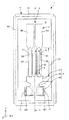
図1および図2に示すように、振動子1は、振動素子2と、振動素子2を収納するパッケージ9とを有している。以下、振動素子2およびパッケージ9ついて、順次詳細に説明する。
1 to 5 show an X axis, a Y ′ axis, and a Z ′ axis as three axes orthogonal to each other. The leading end side of each of the illustrated arrows is “+ (plus)”, and the base end The side is “− (minus)”. The direction parallel to the X axis (second direction) is the “X axis direction”, the direction parallel to the Y ′ axis (first direction) is the “Y ′ axis direction”, and the direction is parallel to the Z ′ axis ( The third direction) is referred to as “Z′-axis direction”. Further, the + Z ′ side (upper side in FIGS. 2 and 4) is also referred to as “upper”, and the −Z ′ side (lower side in FIGS. 2 and 4) is also referred to as “lower”.
As shown in FIGS. 1 and 2, the
《振動素子》
図3および図4に示すように、振動素子2は、水晶基板3と、水晶基板3上に形成された第1駆動用電極84および第2駆動用電極85とを有している。なお、図3では、説明の便宜上、第1駆動用電極84および第2駆動用電極85の図示を一部省略している。
水晶基板3は、水晶で構成されており、水晶の結晶軸である、電気軸としてのX軸、機械軸としてのY軸、および光学軸としてのZ軸のうち、X軸を回転軸として、Z軸をY軸の−Y方向へ+Z側が回転するように所定の角度(例えば、15°未満)傾けた軸をZ’軸、Y軸をZ軸の+Z方向へ+Y側が回転するように所定の角度(例えば、15°未満)傾けた軸をY’軸とし、X軸およびY’軸を含む面を主面とし、Z’軸に沿った方向を厚さとする、所謂Zカット水晶板である。このような構成の水晶基板3では、水晶基板3の長手方向をY’軸、短手方向をX軸、さらに厚さ方向をZ’軸と定めることができる。また、本実施形態では、基部4の上面は、水晶の+Z’面であり、基部4の下面は、水晶の−Z’面である。
<Vibration element>
As shown in FIGS. 3 and 4, the
The
なお、Y’軸およびZ’軸は、それぞれ、Y軸およびZ軸に一致していてもよい(すなわち前記所定角度が0°であってもよい)。
また、本発明に用いられる水晶基板は、Zカット水晶板に限定されるものではなく、ATカット、BTカット、STカット、CTカット、DTカット、GTカットおよびSCカット等の水晶板を広く適用できることは言うまでもない。
Note that the Y ′ axis and the Z ′ axis may coincide with the Y axis and the Z axis, respectively (that is, the predetermined angle may be 0 °).
In addition, the quartz substrate used in the present invention is not limited to the Z-cut quartz plate, but widely applies quartz plates such as AT cut, BT cut, ST cut, CT cut, DT cut, GT cut, and SC cut. Needless to say, you can.
なお、水晶基板3の厚さT(基部4、および振動腕5、6の厚さ)としては、特に限定されないが、70μm未満であるのが好ましい。このような数値範囲とすることにより、例えば、ウェットエッチングによって水晶基板3を形成(パターニング)する場合、振動腕5と基部4の境界部や後述する腕部50とハンマーヘッド59の境界部等に不要部(本来なら除去されるべき部分)が残存してしまうのを効果的に防止することができる。そのため、振動漏れを効果的に低減することのできる振動素子2とすることができる。違う観点から、厚さTは、70μm以上、300μm以下程度であるのが好ましく、100μm以上、150μm以下程度であるのがより好ましい。このような数値範囲とすることにより、第1、第2駆動用電極84、85を水晶基板3の側面に広く形成することができるため、小型化と共にCI値を低くすることができる。
The thickness T of the quartz substrate 3 (the thickness of the
図1に示すように、水晶基板3は、基部4と、1対(2つ)の振動腕5、6とを有しており、所謂「音叉型」をなしている。なお、これら基部4、および振動腕5、6は、一体に形成されている。このような構成の水晶基板3を備える振動素子2は、一対の振動腕5、6が互いに接近、離間を繰り返すように面内方向(XY’平面方向)に所定の共振周波数で屈曲振動する。
As shown in FIG. 1, the
共振周波数としては、例えば31.768kHz以上33.768kHz以下である。
基部4は、X軸およびY’軸に平行な平面であるXY’平面に広がり、Z’軸方向を厚さ方向とする板状をなしている。
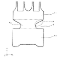
基部4は、Z軸方向から見た平面視(以下、単に「平面視」という)で、基部4のY’軸方向の途中の部分がくびれた形状をなしている。すなわち、図3に示すように、基部4は、振動腕5、6が延出している第1基部41と、第1基部41に対して振動腕5、6とは反対側に設けられた第2基部42と、第1基部41と第2基部42とを連結する連結部43と、を含んでいる。なお、図5において、第1基部41と連結部43との境界部、および、第2基部42と連結部43との境界部をそれぞれ破線で示している。
The resonance frequency is, for example, 31.768 kHz or more and 33.768 kHz or less.
The
The
ここで、連結部43のX軸方向の外縁は、第1基部41よりもX軸方向に沿った幅が徐々に小さくなるように括れ状の切り欠き部Bになっている。言い換えると、連結部43は、第1基部41側の端部にX軸方向に沿った幅が第2基部42側に向かうに従って連続的に小さくなる縮幅部411を有する。これにより、1対の振動腕5、6の互いに同一面内で接近または離間する屈曲振動に伴う第1基部41の変形を効果的に低減することができる。その結果、第1基部41のY軸方向に沿った長さを短くしても、1対の振動腕5、6の、略面内において互いに接近と離間を交互に繰り返す屈曲振動に伴う第1基部41の変形を低減し、基部4から外部への振動漏れを低減することができる。
Here, the outer edge in the X-axis direction of the connecting
連結部43のX軸方向の外縁のうち、楕円で囲まれている領域AAの外縁、すなわち、切り欠き部Bの前記第1基部41の前記一端側、且つ前記連結部43の中央寄りの外縁は、角部を含まない連続的な線で構成されている。したがって、曲線と直線との接続部が曲率の不連続となる角部を有していないため、応力が集中しやすい部分がなくなり、耐衝撃性を十分に高めることができる。
Of the outer edges in the X-axis direction of the connecting
以下、図6および図7に基づいて、縮幅部411の作用について詳述する。
図6(a)は、図3に示す振動素子を模式的に示す平面図(縮幅部を考慮した図)、図6(b)は、(a)に示す振動素子の簡略化モデルを示す平面図である。図7は、図6に示す振動素子の振動漏れ抑制の原理を説明する平面図であって、(a)〜(d)は、基部の各部(第1〜4連結部)の作用を説明する図である。
Hereinafter, the operation of the reduced
6A is a plan view schematically showing the vibration element shown in FIG. 3 (a diagram in consideration of the reduced width portion), and FIG. 6B shows a simplified model of the vibration element shown in FIG. It is a top view. FIG. 7 is a plan view for explaining the principle of suppression of vibration leakage of the vibration element shown in FIG. 6, and (a) to (d) explain the operation of each part (first to fourth connecting parts) of the base part. FIG.
連結部43のX軸方向の外縁のうち、第1基部41側の縮幅部411の外縁は、振動腕の屈曲振動により第1基部41と連結部43の第1基部41側の領域とに生じる変形を低減する効果を有している。
縮幅部411を振動腕5、6の先端方向と反対側に形成した場合を図6(a)に示す。図6(b)に示したように回転軸155を回転の中心とし、所定の半径Rを有する擬似的な剛体の回転体154に弾性棒151が接続されたものと、回転軸157を回転の中心とし、半径Rを有する擬似的な剛体の回転体156に弾性棒152が接続されたものとが、簡略化された基部168によって接続されているものと見做すことができる。
Out of the outer edges of the connecting
FIG. 6A shows a case where the reduced
また、簡略化された基部168の代表的な連結部として、回転軸155、157よりも弾性棒151、152側に設けられた第1の連結部158と、回転軸155、157との間に設けられた第2の連結部159と、回転軸155、157よりも弾性棒の在る方向とは反対側に設けられた第3の連結部160と、第3の連結部160よりも弾性棒の先端方向とは反対側に設けられた第4の連結部169と、を考える。
In addition, as a representative connecting portion of the
2本の振動腕5、6が互いに離間するように屈曲変形した場合、弾性棒151、152が互いに離間するように屈曲変形したと見做すが、この場合、振動腕5、6の根元周辺から振動腕の先端方向とは反対側の方向の所定の場所に、変位ベクトルの渦が形成される。この渦の中心は、基部4を含む振動腕5、6の根元付近である場合が多いが、振動腕5、6や基部4の領域には属さない、仮想的な空間上に形成される場合もある。
When the two vibrating
ここでは説明の都合上、この渦の中心は基部4の領域に属するとし、且つ、弾性棒151、152からの距離は等しいとするとともに、この渦の中心を図6(b)における回転軸155、157とした。なお、この回転軸155、157を回転の中心とし、半径Rを有する擬似的な剛体の回転体154、156の外周の接線方向における変位は、弾性棒151、152の先端方向の側で最も大きく、弾性棒151、152の先端方向とは反対側の方向で最も小さい。
Here, for convenience of explanation, it is assumed that the center of the vortex belongs to the region of the
図7(a)において、簡略化された基部168の代表的な第1の連結部158は、擬似的な剛体の回転体154、156の回転運動によって強く伸ばされながら弾性棒151、152の先端側の方向に小さく移動する。
図7(b)において、簡略化された基部168の代表的な第2の連結部159も同様に、擬似的な剛体の回転体154、156の回転運動によって伸ばされながら弾性棒151、152の先端側の方向に移動する。
In FIG. 7A, a typical first connecting
In FIG. 7B, the representative second connecting
図7(c)において、簡略化された基部168の代表的な第3の連結部160は、擬似的な剛体の回転体154、156の回転運動によって圧縮されながら弾性棒151、152の先端側の方向に移動するが、このとき、第3の連結部160の長さ方向の中央周辺は、弾性棒151、152の先端側の方向、或は弾性棒151、152の先端方向とは反対側の方向のどちらかに変形する潜在力を有している。
図7(d)において、簡略化された基部168の代表的な第4の連結部169の場合は、擬似的な剛体の回転体154、156の回転運動によって圧縮されるが、アーチ形状をしているために変形し難く、更に変形する場合には、第4の連結部169の長さ方向の中央周辺が弾性棒151、152の先端方向とは反対側の方向に変位するように変形する。
In FIG. 7C, the representative third connecting
In the case of the representative fourth connecting
従って、弾性棒151、152の離間運動によって、簡略化された基部168の代表的な第1乃至4の連結部158、159、160、169において、回転軸155と157を結ぶ方向へは圧縮や伸張の変形を発生させながら振動変位を相殺させる作用が働く。そして、第1乃至3の連結部158、159、160が弾性棒151、152の先端側の方向に変位するのを、第4の連結部169の変形し難さが妨げるとともに、第4の連結部169の長さ方向の中央付近が弾性棒151、152の先端方向とは反対側の方向に変位するように変形することで相殺することができる。
結果として、簡略化された基部168に固定部材を形成した場合、即ち、基部167に固定部材を形成した場合、固定部材を介して外部へ漏洩するエネルギーが減少するので、振動漏れを低減させ、Q値の減少を低減することができる。
Accordingly, the first to fourth connecting
As a result, when a fixing member is formed on the
図3に示すように、振動腕5、6は、X軸方向に並び、かつ、互いに平行となるように基部4の先端から+Y’軸方向に延出している。また、振動腕5、6は、それぞれ、長手形状をなしており、その基端が固定端となり、先端が自由端となっている。
また、振動腕5、6は、腕部50、60と、腕部50、60の先端に設けられた錘部としてのハンマーヘッド(腕部50、60よりもX軸方向に沿った長さが長い広幅な錘部)59、69とを有している。振動腕5、6は、互いに同様の構成(形状、大きさ)をなしている。
As shown in FIG. 3, the vibrating
The vibrating
図4に示すように、振動腕5は、XY’平面で構成された互いに表裏の関係にある一対の主面51、52と、Y’Z’平面で構成され、一対の主面51、52を接続する一対の側面53、54とを有している。また、振動腕5は、主面51に開口する有底の溝55(溝部)と、主面52に開口する有底の溝56(溝部)とを有している。溝55、56は、それぞれ、Y’軸方向に延在している。このような振動腕5は、溝55、56が形成されている部分では、略H型の横断面形状をなしている。
As shown in FIG. 4, the resonating
振動腕5と同様に、振動腕6は、XY’平面で構成された互いに表裏の関係にある一対の主面61、62と、Y’Z’平面で構成され、一対の主面61、62を接続する一対の側面63、64とを有している。また、振動腕6は、主面61に開口する有底の溝65(溝部)と、主面62に開口する有底の溝66(溝部)とを有している。溝65、66は、それぞれ、Y’軸方向に延在している。このような振動腕6は、溝65、66が形成されている部分では、略H型の横断面形状をなしている。
Similar to the vibrating
このような溝55、56は、図4に示すように、横断面において、振動腕5の厚さ方向の長さを二等分する線分に対して対称的(上下対称)に形成されているのが好ましい。同様に、溝65、66は、横断面において、振動腕6の厚みを二等分する線分に対して対称的(上下対称)に形成されているのが好ましい。これにより、振動腕5、6の不要な振動を低減でき、振動腕5、6を効率的に水晶基板3の面内方向(XY’平面方向)に振動させることができる。
なお、前述したように、本実施形態では、腕部50は、一対の主面51、52の双方に溝55、56が設けられていたが、溝は、一対の主面51、52のうちの少なくとも一方の主面に設けられていてもよい。また、本発明において、溝は、必要に応じて設けられていなくてもよい。なお、腕部60についても同様である。
As shown in FIG. 4,
As described above, in the present embodiment, the
このような振動腕5には、図4に示すように、一対の第1駆動用電極84と一対の第2駆動用電極85とが形成されている。具体的には、一方の第1駆動用電極84は、溝55の内面に形成されており、他方の第1駆動用電極84は、溝56の内面に形成されている。また、一方の第2駆動用電極85は、側面53に形成されており、他方の第2駆動用電極85は、側面54に形成されている。
As shown in FIG. 4, a pair of
同様に、振動腕6にも、一対の第1駆動用電極84と一対の第2駆動用電極85とが形成されている。具体的には、一方の第1駆動用電極84は、側面63に形成されており、他方の第1駆動用電極84は、側面64に形成されている。また、一方の第2駆動用電極85は、溝65の内面に形成されており、他方の第2駆動用電極85は、溝66の内面に形成されている。
このような第1駆動用電極84と第2駆動用電極85との間に交番電圧を印加すると、振動腕5、6が互いに接近、離間を繰り返すように面内方向(XY’平面方向)に所定の周波数で振動する。
Similarly, a pair of
When an alternating voltage is applied between the
第1駆動用電極84および第2駆動用電極85の構成材料としては、それぞれ、特に限定されないが、例えば、金(Au)、金合金、白金(Pt)、アルミニウム(Al)、アルミニウム合金、銀(Ag)、銀合金、クロム(Cr)、クロム合金、ニッケル(Ni)、銅(Cu)、モリブデン(Mo)、ニオブ(Nb)、タングステン(W)、鉄(Fe)、チタン(Ti)、コバルト(Co)、亜鉛(Zn)、ジルコニウム(Zr)等の金属材料、酸化インジウムスズ(ITO)等の導電材料により形成することができる。
The constituent materials of the
また、図4に示すように、溝55は、第1駆動用電極84(励振電極)が設けられている部分である電極形成領域551と、電極形成領域551に対して基部4とは反対側に位置し、駆動用電極が設けられていない部分である電極未形成領域552と、を有している。同様に、溝56は、電極形成領域561および電極未形成領域562を有し、溝65は、電極形成領域651および電極未形成領域652を有し、溝66は、電極形成領域661および電極未形成領域662を有する。このような電極未形成領域552、562、652、662を形成することにより、高次モードの振動(高調波)の発生を低減しつつ、等価直列容量C1を小さくしたメインモードの振動(基本波)を発生させることができる。こうすることによって、高次モードの等価直列抵抗値をメインモードの等価直列抵抗値よりも大きくすることができるので、振動素子2を搭載した発振回路において、高次モードの共振周波数で発振してしまう虞を低減すると共に、負荷容量の変化に対する発振周波数の変化が増大するのを低減することができる。
また、振動素子2では、振動腕5、6に溝55、56、65、66を形成することによって、熱弾性損失の低減を図っている。以下、このことについて、振動腕5を例にして具体的に説明する。
Further, as shown in FIG. 4, the
In the vibrating
振動腕5は、前述したように、第1、第2駆動用電極84、85間に交番電圧を印加することにより面内方向に屈曲振動する。図8に示すように、この屈曲振動の際、腕部50の側面53が収縮すると側面54が伸張し、反対に、側面53が伸張すると側面54が収縮する。振動腕5がGough−Joule効果を発生しない(エネルギー弾性がエントロピー弾性に対して支配的な)場合、側面53、54のうち、収縮する面側の温度は上昇し、伸張する面側の温度は下降するため、側面53と側面54との間、つまり腕部50の内部に温度差が発生する。このような温度差から生じる熱伝導によって振動エネルギーの損失が発生し、これにより振動素子2のQ値が低下する。このようなQ値の低下を熱弾性効果とも言い、熱弾性効果によるエネルギーの損失を熱弾性損失とも言う。
As described above, the vibrating
振動素子2のような構成の屈曲振動モードで振動する振動素子において、振動腕5の屈曲振動周波数(機械的屈曲振動周波数)fが変化したとき、振動腕5の屈曲振動周波数が熱緩和周波数fmと一致するときにQ値が最小となる。この熱緩和周波数fmは、fm=1/(2πτ)で求めることができる(ただし、式中πは円周率であり、eをネイピア数とすれば、τは温度差が熱伝導によりe−1倍になるのに要する緩和時間である)。
In the vibration element that vibrates in the bending vibration mode configured as the
また、平板構造(断面形状が矩形の構造)の熱緩和周波数をfm0とすれば、fm0は下式で求めることができる。
fm0=πk/(2ρCpa2)‥‥(1)
なお、πは円周率、kは振動腕5の振動方向の熱伝導率、ρは振動腕5の質量密度、Cpは振動腕5の熱容量、aは振動腕5の振動方向の幅である。式(1)の熱伝導率k、質量密度ρ、熱容量Cpに振動腕5の材料そのもの(すなわち水晶)の定数を入力した場合、求まる熱緩和周波数fm0は、振動腕5に溝55、56を設けていない場合の値となる。
If the thermal relaxation frequency of the flat plate structure (structure having a rectangular cross-sectional shape) is fm0, fm0 can be obtained by the following equation.
fm0 = πk / (2ρCpa 2 ) (1)
Here, π is the circumference ratio, k is the thermal conductivity of the vibrating
振動腕5では、側面53、54の間に位置するように溝55、56が形成されている。そのため、振動腕5の屈曲振動時に生じる側面53、54の温度差を熱伝導により温度平衡させるための熱移動経路が溝55、56を迂回するように形成され、熱移動経路が側面53、54間の直線距離(最短距離)よりも長くなる。そのため、振動腕5に溝55、56を設けていない場合と比較して緩和時間τが長くなり、熱緩和周波数fmが低くなる。
In the vibrating
図9は、屈曲振動モードの振動素子のQ値のf/fm依存性を表すグラフである。同図において、点線で示されている曲線F1は、振動素子2のように振動腕に溝が形成されている場合(振動腕の横断面形状がH型の場合)を示し、実線で示されている曲線F2は、振動腕に溝が形成されていない場合(連結腕の横断面形状が矩形の場合)を示している。同図に示すように、曲線F1、F2の形状は変わらないが、前述のような熱緩和周波数fmの低下に伴って、曲線F1が曲線F2に対して周波数低下方向へシフトする。したがって、振動素子2のように振動腕に溝が形成されている場合の熱緩和周波数をfm1とすれば、下記式(2)を満たすことにより、常に、振動腕に溝が形成されている振動素子のQ値が振動腕に溝が形成されていない振動素子のQ値に対して高くなる。
FIG. 9 is a graph showing the f / fm dependency of the Q value of the vibration element in the bending vibration mode. In the figure, a curved line F1 indicated by a dotted line shows a case where a groove is formed in the vibrating arm like the vibrating element 2 (when the cross-sectional shape of the vibrating arm is H-shaped), and is indicated by a solid line. A curved line F2 indicates a case where no groove is formed in the vibrating arm (when the cross-sectional shape of the connecting arm is rectangular). As shown in the figure, the shapes of the curves F1 and F2 are not changed, but the curve F1 shifts in the frequency lowering direction with respect to the curve F2 as the thermal relaxation frequency fm is reduced as described above. Therefore, if the thermal relaxation frequency when the groove is formed in the vibrating arm like the vibrating
![]()
![]()
更に、f/fm0>1の関係に限定すれば、より高いQ値を得ることができる。
なお、図9において、f/fm<1の領域を等温的領域とも言い、この等温的領域ではf/fmが小さくなるにつれてQ値が高くなる。これは、振動腕の機械的周波数が低くなる(振動腕の振動が遅くなる)につれて前述のような振動腕内の温度差が生じ難くなるためである。したがって、f/fmを0(零)に限りなく近づけた際の極限では、等温準静操作となって、熱弾性損失は限りなく0(零)に接近する。一方、f/fm>1の領域を断熱的領域とも言い、この断熱的領域ではf/fmが大きくなるにつれてQ値が高くなる。これは、振動腕の機械的周波数が高くなるにつれて、各側面の温度上昇・温度低下の切り替わりが高速となり、前述のような熱伝導が生じる時間がなくなるためである。したがって、f/fmを限りなく大きくした際の極限では、断熱操作となって、熱弾性損失は限りなく0(零)に接近する。このことから、f/fm>1の関係を満たすとは、f/fmが断熱的領域にあるとも言い換えることができる。
Furthermore, if the relationship is limited to f / fm0> 1, a higher Q value can be obtained.
In FIG. 9, a region where f / fm <1 is also referred to as an isothermal region. In this isothermal region, the Q value increases as f / fm decreases. This is because the temperature difference in the vibrating arm as described above is less likely to occur as the mechanical frequency of the vibrating arm becomes lower (the vibration of the vibrating arm becomes slower). Therefore, in the limit when f / fm is brought close to 0 (zero) as much as possible, the operation becomes an isothermal quasi-static operation, and the thermoelastic loss approaches 0 (zero) as much as possible. On the other hand, a region where f / fm> 1 is also referred to as an adiabatic region. In this adiabatic region, the Q value increases as f / fm increases. This is because, as the mechanical frequency of the vibrating arm increases, the temperature increase / decrease switching on each side surface becomes faster, and there is no time for heat conduction as described above. Therefore, in the limit when f / fm is increased as much as possible, the operation becomes adiabatic, and the thermoelastic loss approaches 0 (zero) as much as possible. From this, satisfying the relationship of f / fm> 1 can be rephrased as f / fm being in the adiabatic region.
また、振動素子2では、fm=πk/(2ρCpa2)としたときにf/fm>1の範囲を満足し、加えて、振動腕5、6に所定の形状の溝55、56、65、66を形成することにより、従来の振動素子よりも高いQ値が得られるように構成されている。以下、振動腕5、6に形成された溝55、56、65、66の構成について具体的に説明する。なお、振動腕5、6は、互いに同様の構成であるため、以下では、振動腕5に形成された溝55、56について代表して説明し、振動腕6に形成された溝65、66については、その説明を省略する。
Further, in the
図4に示すように、振動素子2では、主面51の溝55のX軸方向両側に位置する土手部(振動腕5の長手方向に直交する幅方向に沿って溝55を挟んで並んでいる主面)51a、51bの幅(X軸方向の長さ)が互いにほぼ等しく、その土手部51a、51bの幅をWとし、振動腕5の厚さ(Z’軸方向の長さ)をTとし、溝55、56の最大深さの合計をtaとし、ta/Tをηとしたとき、下記式(3)で示す関係を満足している。
As shown in FIG. 4, in the
4.236×10×η2−8.473×10×η+4.414×10≦W≦−3.367×10×η2+7.112×10×η−2.352×10 [μm] ・・・・(3)
但し、0.75≦η<1.00
なお、主面52の溝56のX軸方向両側に位置する土手部(部位)52a、52bの幅についても同様の関係を満足している。
4.236 × 10 × η 2 −8.473 × 10 × η + 4.414 × 10 ≦ W ≦ −3.367 × 10 × η 2 + 7.112 × 10 × η-2.352 × 10 [μm] (3)
However, 0.75 ≦ η <1.00
The same relationship is satisfied for the widths of the bank portions (parts) 52a and 52b located on both sides of the
振動腕5の少なくとも一部に、式(3)を満足する領域Sが存在することにより、従来よりも優れた振動特性を発揮する振動素子2を得ることができる。なお、式(3)を満足する領域Sは、振動腕5の長手方向の一部に存在していればよいが、振動腕5の基端部を含んで存在していることが好ましい。基端部は、振動腕5の中でも大きく屈曲変形する部分であり、振動腕5の全体の振動特性に影響を与えやすい部位である。そのため、領域Sを少なくとも基端部を含んで存在させることにより、より確実かつ効果的に、従来よりも優れた振動特性を発揮する振動素子2を得ることができる。また、言い換えれば、領域Sを少なくとも振動腕5の屈曲変形量が最大となる部位に存在させることにより、より確実かつ効果的に、従来品よりも優れた振動特性を発揮する振動素子2を得ることができる。より具体的には、領域Sは、腕部50の基端部から先端部へ向かって、腕部50の長さに対して30%の長さの領域を含んで存在していることが好ましいと言える。
Since the region S that satisfies the expression (3) is present in at least a part of the vibrating
図1に示すように、本実施形態の振動素子2では、腕部50がその延出方向の両端部を除くほぼ全域(領域S1)にてほぼ同一の幅および厚さとなるように構成されており、加えて、溝55、56が全域(領域S2)にてほぼ同一の幅および深さとなるように形成されている。振動素子2では、このような領域S1、S2が重なり合う領域が領域Sを構成しているため、領域Sを振動腕5の長手方向に長く存在させることができる。したがって、上述した効果がより顕著となる。
なお、前記式(3)は、熱弾性損失のみを考慮したQ値をQTEDとし、そのQTEDが所定値よりも高くなる条件である。
As shown in FIG. 1, in the
The equation (3) is a condition in which the Q value considering only the thermoelastic loss is defined as Q TED and the Q TED is higher than a predetermined value.
以下、説明を続けるが、QTEDを規格化してその説明を行う。QTEDの規格化は、ηが限りなく1に近いときに予想されるQTEDを1として行う。すなわち、ηが限りなく1に近いときに予想されるQTEDをQTED(η=1)とし、規格化される前のQTEDをQTEDbとし、規格化されたQTEDをQTEDaとしたとき、そのQTEDaは、QTEDb/QTED(η=1)で表される。
まず、前記式(3)は、QTEDa≧0.65となる条件である。そして、QTEDa≧0.70、QTEDa≧0.75、QTEDa≧0.80、QTEDa≧0.85となる条件は、それぞれ、下記の通りである。
Hereinafter, the description will be continued, but Q TED will be standardized and described. Standardization of Q TED performs Q TED expected when η is infinitely close to 1 as one. That is, Q TED expected when η is infinitely close to 1 is Q TED (η = 1), Q TED before standardization is Q TED b, and standardized Q TED is Q TED a Q TED a is expressed by Q TED b / Q TED (η = 1).
First, the expression (3) is a condition that satisfies Q TED a ≧ 0.65. The conditions for Q TED a ≧ 0.70, Q TED a ≧ 0.75, Q TED a ≧ 0.80, and Q TED a ≧ 0.85 are as follows.
(QTEDa≧0.70)
QTEDa≧0.70となる条件は、下記式(4)で示す関係を満足することである。
5.459×10×η2−1.110×10²×η+5.859×10≦W≦−4.500×10×η2+9.490×10×η−3.698×10 [μm] ・・・・(4)
但し、0.80≦η<1.00
(Q TED a ≧ 0.70)
The condition for Q TED a ≧ 0.70 is to satisfy the relationship represented by the following formula (4).
5.459 × 10 × η 2 −1.110 × 10 2 × η + 5.859 × 10 ≦ W ≦ −4.500 × 10 × η 2 + 9.490 × 10 × η−3.698 × 10 [μm] ... (4)
However, 0.80 ≦ η <1.00
(QTEDa≧0.75)
QTEDa≧0.75となる条件は、下記式(5)で示す関係を満足することである。
6.675×10×η2−1.380×10²×η+7.392×10≦W≦−5.805×10×η2+1.228×10²×η−5.267×10 [μm] ・・・・(5)
但し、0.85≦η<1.00
(Q TED a ≧ 0.75)
The condition for Q TED a ≧ 0.75 is to satisfy the relationship represented by the following formula (5).
6.675 × 10 × η 2 −1.380 × 10 2 × η + 7.392 × 10 ≦ W ≦ −5.805 × 10 × η 2 + 1.228 × 10 2 × η−5.267 × 10 [μm] (5)
However, 0.85 ≦ η <1.00
(QTEDa≧0.80)
QTEDa≧0.80となる条件は、下記式(6)で示す関係を満足することである。
7.752×10×η2−1.634×10²×η+8.903×10≦W≦−6.993×10×η2+1.496×10²×η−6.844×10 [μm] ・・・・(6)
但し、0.90≦η<1.00
(Q TED a ≧ 0.80)
The condition for Q TED a ≧ 0.80 is to satisfy the relationship represented by the following formula (6).
7.752 × 10 × η 2 −1.634 × 10 2 × η + 8.903 × 10 ≦ W ≦ −6.993 × 10 × η 2 +1. 496 × 10 2 × η−6.844 × 10 [μm] .... (6)
However, 0.90 ≦ η <1.00
(QTEDa≧0.85)
QTEDa≧0.85となる条件は、下記式(7)で示す関係を満足することである。
−1.847×10×η+2.217×10≦W≦1.189×10×η−8.433 [μm] ・・・・(7)
但し、0.95≦η<1.00
(Q TED a ≧ 0.85)
The condition for Q TED a ≧ 0.85 is to satisfy the relationship expressed by the following formula (7).
−1.847 × 10 × η + 2.217 × 10 ≦ W ≦ 1.189 × 10 × η−8.433 [μm] (7)
However, 0.95 ≦ η <1.00
(QTEDa≧0.90)
QTEDa≧0.90となる条件は、下記式(7´)で示す関係を満足することである。
−3.300×10×η+3.730×10≦W≦3.302×10×η−2.333×10[μm] ・・・・(7´)
但し、0.95≦η<1.00
(Q TED a ≧ 0.90)
The condition for Q TED a ≧ 0.90 is to satisfy the relationship represented by the following formula (7 ′).
-3.300 × 10 × η + 3.730 × 10 ≦ W ≦ 3.32 × 10 × η-2.333 × 10 [μm] (7 ′)
However, 0.95 ≦ η <1.00
以下、発明者が行ったシミュレーションにより解析した結果に基づいて、これらの条件を実証する。
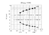
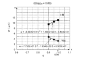
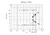
図10は、ウェットエッチングにより形成された振動腕を示す断面図である。図11は、WとQTEDaの関係を示すグラフである。図12〜図17は、それぞれ、ηとWの関係を示すグラフである。
Hereinafter, these conditions will be verified based on the results of analysis by simulation performed by the inventors.
FIG. 10 is a cross-sectional view showing a vibrating arm formed by wet etching. FIG. 11 is a graph showing the relationship between W and Q TED a. 12 to 17 are graphs showing the relationship between η and W, respectively.
なお、以下では、Zカット水晶板をパターニングしてなり、屈曲振動周波数(機械的屈曲振動周波数)f=32.768kHzの振動素子2を用いたシミュレーションを代表して用いるが、発見者によって、屈曲振動周波数fが32.768kHz±1kHzの範囲では、下記に示すシミュレーションによる解析結果とほとんど差がないことが確認されている。
In the following, a Z-cut quartz plate is patterned and a simulation using the
また、本シミュレーションでは、ウェットエッチングによって水晶基板3をパターニングした振動素子2を用いている。したがって、溝55、56は、図10に示すように、水晶の結晶面が現れた形状となっている。なお、図10では、図3中のB−B線断面に相当する断面を示している。−X軸方向のエッチングレートが+X軸方向のエッチングレートよりも低いため、−X軸方向の側面が比較的なだらかな傾斜となり、+X軸方向の側面が垂直に近い傾斜となる。
In this simulation, the
また、本シミュレーションで用いた振動素子2の水晶基板3のサイズは、長さが1160μm、幅が520μm、厚さ、すなわち、振動腕5、6のそれぞれの厚さTが120μmである。なお、発見者らによって、長さ、幅、厚さを変更しても、下記に示すシミュレーション結果とほとんど差がないことが確認されている。また、本シミュレーションには、第1、第2駆動用電極84、85が形成されていない振動素子2を用いた。
The
図11は、ηを、それぞれ、0.40、0.60、0.70、0.75、0.80、0.85、0.90、0.95、0.99としたときの、土手部51a、51b、52a、52bの幅WとQTEDaとの関係を示すグラフである。また、振動素子2にて達成すべきQTEDaの下限値Qminを0.65とし、線分L1で示している。QTEDaをこの値以上とすることにより、優れた振動特性を発揮することができる。
FIG. 11 shows a bank when η is 0.40, 0.60, 0.70, 0.75, 0.80, 0.85, 0.90, 0.95, and 0.99, respectively. It is a graph which shows the relationship between the width W of
図11から、ηが0.75、0.80、0.85、0.90、0.95、0.99のときに、QTEDaが0.65以上の領域が存在することが読み取れる。このことから、前述したように、QTEDa≧0.65とするには、「0.75≦η<1.00」なる関係を満足する必要があることが読み取れる。
また、図12は、図11において各グラフがQTEDa=0.65とクロスする各点をプロットして得られたグラフであり、QTEDa=0.65(Qmin)である場合におけるηとWの関係を示すグラフである。
From FIG. 11, it can be seen that there is a region where Q TED a is 0.65 or more when η is 0.75, 0.80, 0.85, 0.90, 0.95, and 0.99. From this, as described above, it can be read that it is necessary to satisfy the relationship of “0.75 ≦ η <1.00” in order to satisfy Q TED a ≧ 0.65.
FIG. 12 is a graph obtained by plotting each point where each graph crosses Q TED a = 0.65 in FIG. 11, and in the case where Q TED a = 0.65 (Q min ). It is a graph which shows the relationship between (eta) and W.
この場合、Wの下限値を示すグラフは、下記式(8)で示される。
W[μm]=4.236×10×η2−8.473×10×η+4.414×10[μm] ・・・・(8)
また、Wの上限値を示すグラフは、下記式(9)で示される。
W[μm]=−3.367×10×η2+7.112×10×η−2.352×10[μm] ・・・・(9)
したがって、図12から、前記式(3)で示す関係を満たすことにより、0.65以上のQTEDaを有する振動素子2が得られることが読み取れる。以上より、式(3)を満足することにより、0.65以上の高いQTEDaが得られ、振動特性に優れた振動素子2となることが証明される。
In this case, a graph indicating the lower limit value of W is represented by the following formula (8).
W [μm] = 4.236 × 10 × η 2 −8.473 × 10 × η + 4.414 × 10 [μm] (8)
Moreover, the graph which shows the upper limit of W is shown by following formula (9).
W [μm] = − 3.367 × 10 × η 2 + 7.112 × 10 × η−2.352 × 10 [μm] (9)
Therefore, it can be seen from FIG. 12 that the
同様に、図11から、ηが0.80、0.85、0.90、0.95、0.99のときに、QTEDaが0.70以上の領域が存在することが読み取れる。このことから、前述したように、QTEDa≧0.70とするには、「0.80≦η<1.00」なる関係を満足する必要があることが読み取れる。
また、図13は、図11において各グラフがQTEDa=0.70とクロスする各点をプロットして得られたグラフであり、QTEDa=0.70(Qmin)である場合におけるηとWの関係を示すグラフである。
Similarly, it can be seen from FIG. 11 that when η is 0.80, 0.85, 0.90, 0.95, and 0.99, there is a region where Q TED a is 0.70 or more. From this, as described above, it can be read that in order to satisfy Q TED a ≧ 0.70, it is necessary to satisfy the relationship of “0.80 ≦ η <1.00”.
FIG. 13 is a graph obtained by plotting each point where each graph crosses Q TED a = 0.70 in FIG. 11, and in the case where Q TED a = 0.70 (Q min ). It is a graph which shows the relationship between (eta) and W.
この場合、Wの下限値を示すグラフは、下記式(10)で示される。
W[μm]=5.459×10×η2−1.110×10²×η+5.859×10[μm] ・・・・(10)
また、Wの上限値を示すグラフは、下記式(11)で示される。
W[μm]=−4.500×10×η2+9.490×10×η−3.698×10[μm] ・・・・(11)
したがって、図13から、前記式(4)で示す関係を満たすことにより、0.70以上のQTEDaを有する振動素子2が得られることが読み取れる。以上より、式(4)を満足することにより、0.70以上の高いQTEDaが得られ、振動特性に優れた振動素子2となることが証明される。
In this case, the graph indicating the lower limit value of W is represented by the following formula (10).
W [μm] = 5.459 × 10 × η 2 −1.110 × 10 2 × η + 5.859 × 10 [μm] (10)
Moreover, the graph which shows the upper limit of W is shown by following formula (11).
W [μm] = − 4.500 × 10 × η 2 + 9.490 × 10 × η−3.698 × 10 [μm] (11)
Therefore, it can be seen from FIG. 13 that the
同様に、図11から、ηが0.85、0.90、0.95、0.99のときに、QTEDaが0.75以上の領域が存在することが読み取れる。このことから、前述したように、QTEDa≧0.75とするには、「0.85≦η<1.00」なる関係を満足する必要があることが読み取れる。
また、図14は、図11において各グラフがQTEDa=0.75とクロスする各点をプロットして得られたグラフであり、QTEDa=0.75(Qmin)である場合におけるηとWの関係を示すグラフである。
Similarly, it can be seen from FIG. 11 that there is a region where Q TED a is 0.75 or more when η is 0.85, 0.90, 0.95, and 0.99. From this, as described above, it can be read that in order to satisfy Q TED a ≧ 0.75, it is necessary to satisfy the relationship of “0.85 ≦ η <1.00”.
FIG. 14 is a graph obtained by plotting each point where each graph crosses Q TED a = 0.75 in FIG. 11, and in the case where Q TED a = 0.75 (Q min ). It is a graph which shows the relationship between (eta) and W.
この場合、Wの下限値を示すグラフは、下記式(12)で示される。
W[μm]=6.675×10×η2−1.380×10²×η+7.392×10[μm] ・・・・(12)
また、Wの上限値を示すグラフは、下記式(13)で示される。
W[μm]=−5.805×10×η2+1.228×10²×η−5.267×10[μm] ・・・・(13)
したがって、図14から、前記式(5)で示す関係を満たすことにより、0.75以上のQTEDaを有する振動素子2が得られることが読み取れる。以上より、式(5)を満足することにより、0.75以上の高いQTEDaが得られ、振動特性に優れた振動素子2となることが証明される。
In this case, a graph indicating the lower limit value of W is represented by the following formula (12).
W [μm] = 6.675 × 10 × η 2 −1.380 × 10 2 × η + 7.392 × 10 [μm] (12)
Moreover, the graph which shows the upper limit of W is shown by following formula (13).
W [μm] = − 5.805 × 10 × η 2 + 1.228 × 10 2 × η−5.267 × 10 [μm] (13)
Therefore, it can be seen from FIG. 14 that the
同様に、図11から、ηが0.90、0.95、0.99のときに、QTEDaが0.80以上の領域が存在することが読み取れる。このことから、前述したように、QTEDa≧0.80とするには、「0.90≦η<1.00」なる関係を満足する必要があることが読み取れる。
また、図15は、図11において各グラフがQTEDa=0.80とクロスする各点をプロットして得られたグラフであり、QTEDa=0.80(Qmin)である場合におけるηとWの関係を示すグラフである。
Similarly, it can be seen from FIG. 11 that there is a region where Q TED a is 0.80 or more when η is 0.90, 0.95, and 0.99. From this, as described above, it can be read that in order to satisfy Q TED a ≧ 0.80, it is necessary to satisfy the relationship “0.90 ≦ η <1.00”.
FIG. 15 is a graph obtained by plotting each point where each graph crosses Q TED a = 0.80 in FIG. 11, and in the case where Q TED a = 0.80 (Q min ). It is a graph which shows the relationship between (eta) and W.
この場合、Wの下限値を示すグラフは、下記式(14)で示される。
W[μm]=7.752×10×η2−1.634×10²×η+8.903×10[μm] ・・・・(14)
また、Wの上限値を示すグラフは、下記式(15)で示される。
W[μm]=−6.993×10×η2+1.496×10²×η−6.844×10[μm] ・・・・(15)
したがって、図15から、前記式(6)で示す関係を満たすことにより、0.80以上のQTEDaを有する振動素子2が得られることが読み取れる。以上より、式(6)を満足することにより、0.80以上の高いQTEDaが得られ、振動特性に優れた振動素子2となることが証明される。
In this case, a graph indicating the lower limit value of W is represented by the following formula (14).
W [μm] = 7.752 × 10 × η 2 −1.634 × 10 2 × η + 8.903 × 10 [μm] (14)
Moreover, the graph which shows the upper limit of W is shown by following formula (15).
W [μm] = − 6.993 × 10 × η 2 + 1.496 × 10 2 × η−6.844 × 10 [μm] (15)
Therefore, it can be seen from FIG. 15 that the
同様に、図11から、ηが0.95、0.99のときに、QTEDaが0.85以上の領域が存在することが読み取れる。このことから、前述したように、QTEDa≧0.85とするには、「0.95≦η<1.00」なる関係を満足する必要があることが読み取れる。
また、図16は、図11において各グラフがQTEDa=0.85とクロスする各点をプロットして得られたグラフであり、QTEDa=0.85(Qmin)である場合におけるηとWの関係を示すグラフである。
Similarly, it can be seen from FIG. 11 that there is a region where Q TED a is 0.85 or more when η is 0.95 or 0.99. From this, as described above, it can be read that it is necessary to satisfy the relationship of “0.95 ≦ η <1.00” in order to satisfy Q TED a ≧ 0.85.
FIG. 16 is a graph obtained by plotting each point where each graph crosses Q TED a = 0.85 in FIG. 11, and in the case where Q TED a = 0.85 (Q min ). It is a graph which shows the relationship between (eta) and W.
この場合、Wの下限値を示すグラフは、下記式(16)で示される。
W[μm]=−1.847×10×η+2.217×10[μm] ・・・・(16)
また、Wの上限値を示すグラフは、下記式(17)で示される。
W[μm]=1.189×10×η−8.433[μm] ・・・・(17)
したがって、図16から、前記式(7)で示す関係を満たすことにより、0.85以上のQTEDaを有する振動素子2が得られることが読み取れる。以上より、式(7)を満足することにより、0.85以上の高いQTEDaが得られ、振動特性に優れた振動素子2となることが証明される。
なお、図17は、図11において各グラフがQTEDa=0.90とクロスする各点をプロットして得られたグラフであり、QTEDa=0.90(Qmin)である場合におけるηとWの関係を示すグラフである。
In this case, the graph indicating the lower limit value of W is represented by the following formula (16).
W [μm] = − 1.847 × 10 × η + 2.217 × 10 [μm] (16)
Moreover, the graph which shows the upper limit of W is shown by following formula (17).
W [μm] = 1.189 × 10 × η−8.433 [μm] (17)
Therefore, it can be read from FIG. 16 that the
FIG. 17 is a graph obtained by plotting each point where each graph crosses Q TED a = 0.90 in FIG. 11, and in the case where Q TED a = 0.90 (Q min ). It is a graph which shows the relationship between (eta) and W.
この場合、Wの下限値を示すグラフは、下記式(16´)で示される。
W=−3.300×10×η+3.730×10 [μm] ・・・・(16´)
また、Wの上限値を示すグラフは、下記式(17´)で示される。
W=3.302×10×η−2.333×10 [μm] ・・・・(17´)
したがって、図17から、前記式(7´)で示す関係を満たすことにより、0.90以上のQTEDaを有する振動素子2が得られることが読み取れる。以上より、式(7´)を満足することにより、0.90以上の高いQTEDaが得られ、振動特性に優れた振動素子2となることが証明される。
In this case, the graph indicating the lower limit value of W is represented by the following formula (16 ′).
W = -3.300 × 10 × η + 3.730 × 10 [μm] (16 ′)
Moreover, the graph which shows the upper limit of W is shown by following formula (17 ').
W = 3.302 × 10 × η−2.333 × 10 [μm] (17 ′)
Therefore, it can be read from FIG. 17 that the
上記のような構成の腕部50、60の先端には、図3に示すように、ハンマーヘッド59、69が設けられている。ハンマーヘッド59は、腕部50よりも幅(X軸方向の長さ)が広く、腕部50からX軸方向の両側へ突出している。また、ハンマーヘッド69は、腕部60よりも幅(X軸方向の長さ)が広く、腕部60からX軸方向の両側へ突出している。
As shown in FIG. 3, hammer heads 59 and 69 are provided at the tips of the
ハンマーヘッド59、69を設けることで、振動腕5、6の全長を抑えつつ、振動腕5の先端側の質量を高めることができる。振動腕5、6の全長を抑える、すなわち振動腕5、6の長さLを短くすることができることにより、振動腕5、6の面内に屈曲振動より変位する振動腕5、6の先端部の変位量を小さくすることができ、振動速度を遅くすることができる。すなわち、ハンマーヘッド59、69を設けることにより、所定の周波数(例えば32.768kHz)で振動させる場合、ハンマーヘッド59、69を設けていないものに比べて、振動速度を遅くすることができる。このように振動速度をより遅くすることができることで、振動素子2に加わる空気抵抗を小さくすることができ、よって、Q値の劣化をより低減することができる。
By providing the hammer heads 59 and 69, it is possible to increase the mass of the
また、ハンマーヘッド59、69をも設けることにより、振動素子2の小型化を図ることができ、よって振動子1の小型化が図れる。
さらに、振動腕5、6の全長を一定とした場合、振動腕5、6の先端部にハンマーヘッド59、69を設けることにより低下する屈曲振動の共振周波数を、腕部50、60の幅(X軸方向に沿った長さ)を拡げることによって、ハンマーヘッド59、69を設ける前と同一の共振周波数に維持すれば、屈曲振動時に腕部50、60で発生する熱が、腕部50、60のX軸方向に沿って流れるための経路が長くなるので、前述したように、断熱的領域において熱弾性損失を低減することによってQ値を向上させ、それと共にCI値を小さくすることができる。
なお、ハンマーヘッド59、69の表裏主面のうち少なくとも一方には、周波数調整用の錘材料が形成されていてもよい。
Further, by providing the hammer heads 59 and 69, the
Furthermore, when the total length of the vibrating
A weight material for frequency adjustment may be formed on at least one of the front and back main surfaces of the hammer heads 59 and 69.
以下に、振動腕5、6の全長と、ハンマーヘッド59、69の長さの関係について説明する。振動腕5、6は、互いに同様の構成であるため、以下では、振動腕5について代表して説明し、振動腕6については、その説明を省略する。
また、振動素子2では、振動腕5の全長(Y’軸方向の長さ)をLとし、ハンマーヘッド59の全長(Y’軸方向の長さ)をHとしたとき、振動腕5は、0.183≦H/L≦0.597なる関係を満足していことが好ましい。このような関係を満足することによって、振動素子2に加わる空気抵抗をより小さくすることができ、Q値の更なる向上を図ることができる。
Hereinafter, the relationship between the total length of the vibrating
In the
ここで、本実施形態では、振動腕5の基端を、側面54が基部4と接続されている箇所と、側面53が基部4と接続されている箇所を結んだ線分の、振動腕5の幅(X軸方向の長さ)中心に位置する箇所に設定している。また、本実施形態では、ハンマーヘッド59は、腕部50の幅(X軸方向の長さ)に対して1.5倍以上の幅を有する領域としている。
Here, in the present embodiment, the vibrating
以下、0.183≦H/L≦0.597なる関係を満足することによって、上記効果を発揮することができることをシミュレーション結果に基づいて証明する。
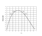
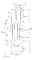
図18は、H/Lと規格化値の関係を示すグラフである。図19は、シミュレーションに用いた振動腕5の形状および大きさを示す斜視図である。図20は、H/Lと高性能化指数1との関係を示すグラフである。
Hereinafter, it will be proved based on simulation results that the above effect can be exhibited by satisfying the relationship of 0.183 ≦ H / L ≦ 0.597.
FIG. 18 is a graph showing the relationship between H / L and the normalized value. FIG. 19 is a perspective view showing the shape and size of the vibrating
図18には、ハンマーヘッド59の長さHと振動腕5の共振周波数との関係を指数化した曲線G1と、ハンマーヘッド59の長さHと振動腕5のQ値の関係を指数化した曲線G2とが示されている。また、曲線G2で示すQ値は、熱弾性損失のみを考慮したものである。また、以下では、曲線G1の縦軸を「低周波化指数」とも言い、曲線G2の縦軸を「高Q値化指数」とも言う。
In FIG. 18, a curve G1 obtained by indexing the relationship between the length H of the
また、曲線G1、G2を求めるためのシミュレーションは、1本の振動腕5を用いて行った。本シミュレーションで用いた振動腕5は、水晶Z板(回転角0°)で構成されている。なお、図19には、互いに直交する3つの軸として、X軸、Y軸およびZ軸が図示されており、図19に示すX軸、Y軸およびZ軸は、それぞれ、水晶のX軸(電気軸)、Y軸(機械軸)およびZ軸(光学軸)に対応している。
The simulation for obtaining the curves G1 and G2 was performed using one vibrating
図19に示すように、振動腕5のサイズは、全長Lが1210μm、厚さTが100μm、腕部50の幅W1が98μm、ハンマーヘッド59の幅W2が172μm、溝55、56の深さtが共に45μm、土手部51a、51b、52a、52bの幅Wがそれぞれ6.5μmである。
このような振動腕5において、ハンマーヘッド59の長さHを変化させてシミュレーションを行った。なお、発明者らによって、振動腕5のサイズ(L、W、W1、W2、T)を変更しても、下記に示すシミュレーション結果と同様の傾向となることが確認されている。
As shown in FIG. 19, the vibrating
In such a vibrating
図18では、曲線G1が規格化値(低周波化指数)=1となる点(H/L=0.51)で、最も振動腕5の共振周波数が低下していることを意味しており、曲線G2が規格化値(高Q値化指数)=1となる点(H/L=0.17)で、最も振動腕5のQ値が高いことを意味している。振動腕5の共振周波数が低い程、振動素子2を小型化することができるため、H/L=0.51(以下「条件1」とも言う)とすることで、最も振動素子2を小型化することができる。また、Q値を高くする程、熱弾性損失が小さく、優れた振動特性を発揮することができるため、H/L=0.17(以下「条件2」とも言う)とすることで、最も優れた振動特性を有する振動素子2とすることができる。
In FIG. 18, it is meant that the resonance frequency of the vibrating
しかしながら、図18からも分かるように、H/L=0.51では、高Q値化指数が十分に高くなく、H/L=0.17では、低周波化指数が十分に高くない。したがって、条件1を満足するだけでは、優れた振動特性を得ることができず、反対に、条件2を満足するだけでは、振動素子2の小型化を十分に図ることができない。
そこで、振動素子2の小型化と振動特性の向上とを両立するための指数として「高性能化指数1」を設定し、高性能化指数1とH/Lとの関係を図20に示した。なお、[高性能化指数1]は、[低周波化指数]×[高Q値化指数]×[補正値]で表される。また、高性能化指数1は、その中で最大であった数値を1としたときの指数である。また、前記[補正値]は、1本の振動腕5で行ったシミュレーションを、2本の振動腕5、6を有する振動素子2へ適合させるための補正値である。そのため、補正値を用いることで、高性能化指数1をより振動素子2の物性に近づけることができる。
However, as can be seen from FIG. 18, the high Q index is not sufficiently high at H / L = 0.51, and the low frequency index is not sufficiently high at H / L = 0.17. Therefore, excellent vibration characteristics cannot be obtained only by satisfying the
Therefore, “
ここで、高性能化指数1が0.8以上であれば、十分に、小型化と振動特性の向上とを両立させた振動素子2が得られる。そのため、振動素子2では、0.183≦H/L≦0.597なる関係を満足するようにハンマーヘッド59の長さHを設定することが好ましい。また、この範囲の中でも、高性能化指数1が0.9以上となるように、0.238≦H/L≦0.531なる関係を満足することがより好ましい。これにより、振動素子2に加わる空気抵抗をより小さくすることができ、Q値の更なる向上を図ることができる。
そのため、小型化と振動特性の向上とをさらに両立させた振動素子2を得ることができる。
Here, if the
Therefore, it is possible to obtain the
また、上述したような違う観点から、振動腕5の全長(Y’軸方向の長さ)をLとし、ハンマーヘッド59の長さ(Y’軸方向の長さ)をHとしたとき、振動腕5は、0.012<H/L<0.30なる関係を満足していことが好ましく、0.046<H/L<0.223なる関係を満足しているのがより好ましい。このような関係を満足することによって、振動素子2に加わる空気抵抗をより小さくすることができるとともに、振動素子2のCI値を低く抑えられることができ、振動損失がより少なくなる。これにより、Q値の劣化を低減することができ、優れた振動特性を有する振動素子2となる。
Further, from the different viewpoints as described above, when the total length of the vibrating arm 5 (the length in the Y′-axis direction) is L and the length of the hammer head 59 (the length in the Y′-axis direction) is H, the vibration is generated. The
また、振動腕5は、腕部50の幅(X軸方向の長さ)をW1とし、ハンマーヘッド59の幅(X軸方向の長さ)をW2としたとき、1.5≦W2/W1≦10.0なる関係を満足していることが好ましく、1.6≦W2/W1≦7.0なる関係を満足しているのがより好ましい。このような関係を満足することにより、ハンマーヘッド59の幅を広く確保することができる。そのため、ハンマーヘッド59の長さHが上述のように比較的短くても(Lの30%未満であっても)、ハンマーヘッド59による質量効果を十分に発揮することができる。したがって、上記関係を満足することによって、振動腕5の全長Lが抑えされることができるため、振動素子2に加わる空気抵抗に起因したQ値の劣化をより低減することができるとともに、振動素子2の小型化をさらに図ることができ、また、ハンマーヘッド59の幅が広すぎることに起因する、屈曲振動時における振動腕5の捩れが増大することに起因する振動漏れの増大を低減することができる。
The vibrating
このように、振動腕5では、0.012<H/L<0.30なる関係と、1.5≦W2/W1≦10.0なる関係とを満足することによって、これら2つの関係の相乗効果によって、小型で、振動素子2に加わる空気抵抗をより小さく、CI値がより抑えられた振動素子2が得られる。
なお、L≦2μm、好ましくは、L≦1μmとすることで、携帯型音楽機器やICカードのようなものに搭載する発振器に使用する、小型な振動素子を得ることができる。また、W1≦100μm、好ましくは、W1≦50μmとすることで、上記Lの範囲においても、低消費電力を実現する発振回路に使用する、低周波で共振する振動素子を得ることができる。また、断熱的領域であれば、水晶Z板でY’方向に振動腕が延び、X方向に屈曲振動する場合、W1≧12.8μmであることが好ましく、水晶Z板でX方向に振動腕が延び、Y’方向に屈曲振動する場合、W1≧14.4μmであることが好ましく、水晶X板でY’方向に振動腕が延び、Z’方向に屈曲振動する場合、W1≧15.9μmであることが好ましい。こうすることによって、確実に断熱的領域にすることができるので、溝の形成により熱弾性損失が減少してQ値が向上し、それと共に溝が形成されている領域で駆動することにより(電界効率が高く、駆動面積が稼げる)CI値が低くなる。
As described above, the vibrating
Note that when L ≦ 2 μm, preferably L ≦ 1 μm, a small vibration element used for an oscillator mounted on a portable music device or an IC card can be obtained. In addition, by setting W1 ≦ 100 μm, preferably W1 ≦ 50 μm, it is possible to obtain a resonator element that resonates at a low frequency and is used in an oscillation circuit that achieves low power consumption even in the range of L. In the adiabatic region, when the vibrating arm extends in the Y ′ direction and vibrates in the X direction on the quartz Z plate, W1 ≧ 12.8 μm is preferable, and the vibrating arm in the X direction on the quartz Z plate. W1 ≧ 14.4 μm, and when the vibrating arm extends in the Y ′ direction and bends and vibrates in the Z ′ direction, it is preferable that W1 ≧ 15.9 μm. It is preferable that In this way, since it can be surely made an adiabatic region, the thermoelastic loss is reduced by the formation of the groove, the Q value is improved, and by driving in the region where the groove is formed (electric field) (High efficiency and drive area can be obtained) The CI value becomes low.
以下、0.012<H/L<0.30なる関係と、1.5≦W2/W1≦10.0なる関係とを満足することによって、上記効果を発揮することができることをシミュレーション結果に基づいて証明する。
図21は、実効幅aを説明する斜視図である。図22は、ハンマーヘッド占有率と低R1化指数の関係を示すグラフである。また、下記の表1は、ハンマーヘッド59の長さHを変化させたときのCI値の変化を示す表である。
Based on the simulation results, the following effects can be exhibited by satisfying the relationship of 0.012 <H / L <0.30 and the relationship of 1.5 ≦ W2 / W1 ≦ 10.0. Prove that.
FIG. 21 is a perspective view for explaining the effective width a. FIG. 22 is a graph showing the relationship between the hammerhead occupancy and the low R1 index. Table 1 below shows the change in CI value when the length H of the
また、本シミュレーションは、図19に示すような、1本の振動腕5を用いて行った。なお、発見者らによって、振動腕5のサイズ(L、W、W1、W2、T)を変更しても、下記に示すシミュレーション結果と同様の傾向となることが確認されている。
本シミュレーションでは、次のようにして、各サンプルのCI値を算出している。まず、有限要素法によって、熱弾性損失のみを考慮したQ値を求める。次に、Q値は、周波数依存性を有しているため、求められたQ値を32.768kHz時のQ値(F変換後Q値)に換算する。次に、F変換後Q値に基づいて、R1(CI値)を算出する。なお、Q値が十分に高い場合(例えば1万以上)には、等価直列抵抗R1とクリスタルインピーダンスCIは略等しいので、本発明では同一視している。次に、CI値も周波数依存性を有しているため、求められたR1を32.768kHz時のR1に換算し、その逆数をとって「低R1指数」とした。低R1指数は、全てのシミュレーションの中で最大であった逆数を1としたときの指数である。したがって、低R1指数が1に近い程、CI値が小さいことを意味している。図22(a)に、横軸にハンマーヘッド占有率(H/L)、縦軸に低R1化指数をプロットしたグラフを示し、図22(b)に同図(a)の一部を拡大したグラフを示す。
Further, this simulation was performed using a single vibrating
In this simulation, the CI value of each sample is calculated as follows. First, the Q value considering only the thermoelastic loss is obtained by the finite element method. Next, since the Q value has frequency dependence, the obtained Q value is converted into a Q value at 32.768 kHz (Q value after F conversion). Next, R1 (CI value) is calculated based on the Q value after F conversion. Note that when the Q value is sufficiently high (for example, 10,000 or more), the equivalent series resistance R1 and the crystal impedance CI are substantially equal, and are therefore regarded as the same in the present invention. Next, since the CI value also has frequency dependency, the obtained R1 is converted to R1 at 32.768 kHz, and the reciprocal thereof is taken as the “low R1 index”. The low R1 index is an index when the reciprocal that is the maximum in all the simulations is 1. Therefore, the closer the low R1 index is to 1, the smaller the CI value. FIG. 22A shows a graph in which the horizontal axis represents the hammerhead occupancy (H / L) and the vertical axis plots the low R1 index, and FIG. 22B is an enlarged view of part of FIG. The graph is shown.
なお、Q値をF変換後Q値へ換算する方法は、次の通りである。
下記式(18)、(19)を用いて次のような計算を行った。
f0=πk/(2ρCpa2)…(18)
Q={ρCp/(Cα2H)}×[{1+(f/f0)2}/(f/f0)]…(19)
ただし、式(18)、(19)中のπは円周率、kは振動腕5の幅方向の熱電導率、ρは質量密度、Cpは熱容量、Cは振動腕5の長さ方向の伸縮の弾性スティフネス定数、αは振動腕5の長さ方向の熱膨張率、Hは絶対温度、fは固有周波数である。また、aは、振動腕5を図21に示すような平板形状として見做したきの幅(実効幅)である。なお、図21では、振動腕5に溝55、56が形成されていないが、この際のaの値を用いてもF変換後Q値への換算を行うことができる。
The method of converting the Q value into the Q value after F conversion is as follows.
The following calculations were performed using the following formulas (18) and (19).
f 0 = πk / (2ρCpa 2 ) (18)
Q = {ρCp / (Cα 2 H)} × [{1+ (f / f 0 ) 2 } / (f / f 0 )] (19)
In equations (18) and (19), π is the circularity, k is the thermal conductivity in the width direction of the vibrating
まず、シミュレーションで用いた振動腕5の固有周波数をF1とし、求められたQ値をQ1とし、式(18)、(19)を用いて、f=F1、Q=Q1となるようなaの値を求める。次に、求められたaを用い、また、f=32.768kHzとし、式(19)からQの値を算出する。このようにして得られたQ値がF変換後Q値となる。
First, the natural frequency of the vibrating

発明者らは、低R1化指数が0.87以上となる振動素子2を求めている。表1および図22のグラフから分かるように、0.012<H/L<0.30なる関係を満足するもの(SIM002〜SIM011)では低R1化指数が目標の0.87以上となっている。特に、0.046<H/L<0.223なる関係を満足するもの(SIM003〜SIM008)では低R1化指数が0.95を超えており、よりCI値が低くなっていることが分かる。以上のシミュレーション結果から、0.012<H/L<0.30なる関係を満足することにより、CI値がより抑えられている振動素子2が得られることが証明された。
以上のような構成の振動素子2は、導電性接着剤11を介してパッケージ9のベース91に固定されている(図2参照)。以下、パッケージ9について説明する。
The inventors are seeking a
The
《パッケージ》
図1および図2に示すように、パッケージ9は、上面に開放する凹部911を有する箱状のベース91と、凹部911の開口を塞ぐようにベース91に接合されている板状のリッド92とを有している。このようなパッケージ9は、凹部911がリッド92にて塞がれることにより形成された収容空間Aを有しており、この収容空間Aに振動素子2が気密的に収納されている。すなわち、ベース91とリッド92とによって画成された収容空間Aは、振動素子2を収容する収容部として機能している。なお、収容空間A内は、窒素、ヘリウム、アルゴン等の不活性ガスが封入されていてもよい。
また、凹部911には、段差部912が設けられており、振動素子2は、基部4の第2基部42にて、例えば、エポキシ系、アクリル系の樹脂に導電性フィラーを混合した導電性接着剤11を介して段差部912に固定されている。
"package"
As shown in FIG. 1 and FIG. 2, the
Further, the
ベース91の構成材料としては、特に限定されないが、酸化アルミニウム等の各種セラミックスを用いることができる。また、リッド92の構成材料としては、特に限定されないが、ベース91の構成材料と線膨張係数が近似する部材であると良い。例えば、ベース91の構成材料を前述のようなセラミックスとした場合には、コバール等の合金とするのが好ましい。なお、ベース91とリッド92の接合は、特に限定されず、例えば、接着剤を介して接合してもよいし、シーム溶接等により接合してもよい。
The constituent material of the
また、ベース91の段差部912には、接続端子951、961が形成されている。図示しないが、振動素子2の第1駆動用電極84は、基部4の第2基部42まで引き出されており、当該部分にて、導電性接着剤11を接続端子951と電気的に接続されている。同様に、図示しないが、振動素子2の第2駆動用電極85は、基部4の第2基部42まで引き出されており、当該部分にて、導電性接着剤11を介して接続端子961と電気的に接続されている。
In addition,
また、接続端子951は、ベース91を貫通する貫通電極(図示せず)を介してベース91の底面に形成された外部端子(図示せず)に電気的に接続されており、接続端子961は、ベース91を貫通する貫通電極(図示せず)を介してベース91の底面に形成された外部端子(図示せず)に電気的に接続されている。
接続端子951、961、貫通電極および外部端子の構成としては、それぞれ、導電性を有していれば、特に限定されないが、例えば、Cr(クロム)、W(タングステン)などのメタライズ層(下地層)に、Ni(ニッケル)、Au(金)、Ag(銀)、Cu(銅)などの各被膜を積層した金属被膜で構成することができる。
The
The configuration of the
ここで、前述したように、振動子1は、振動素子2が備える振動腕5、6が互いに接近、離間を繰り返すように面内方向(XY’平面方向)に所定の周波数で振動する。しかしながら、振動素子2が収容されているパッケージ9内の空気抵抗(空気が有する粘性)の大きさによっては、振動子1(振動素子2)のQ値が劣化すると共に、CI値が増加してしまう。
Here, as described above, the
そこで、本発明では、収容空間Aの減圧の程度(真空度)、すなわち、パッケージ9内の気圧(圧力)を、100Pa以下とした。これにより、振動素子2に加わる空気抵抗を小さくすることができる。そのため、パッケージ9内の空気抵抗に起因する振動子1(振動素子2)のQ値の劣化を低減することができ、それに伴ってCI値の増加を抑制することができる。これにより、Q値の向上を図ることができ、振動子1の振動特性を安定させることができる。
また、パッケージ9内の気圧は、100Pa以下であれば、特に限定されないが、さらに、10Pa以下であることが好ましい。これにより、振動素子2に加わる空気抵抗をさらに小さくすることができ、Q値の更なる向上を図ることができる。
Therefore, in the present invention, the degree of decompression (vacuum degree) of the accommodation space A, that is, the atmospheric pressure (pressure) in the
The atmospheric pressure in the
また、パッケージ9内の気圧は、さらに、7×10⁻⁴以上であることが好ましい。これにより、パッケージ9内とパッケージ9外との気圧の違いにより生じるパッケージ9の不本意な反りや撓み、およびこれらに起因するクラックの発生等を低減することができる。そのため、より信頼性の高い振動子1を得ることができる。また、パッケージ9内の気圧が上記数値と下回っても、振動素子2に加わる空気抵抗に起因するQ値の劣化を低減する効果のそれ以上の向上は期待できないばかりか、振動子1の生産性が低下するおそれがある。
Further, the air pressure in the
このようなことから、パッケージ9内の気圧は、100Pa以下であれば、特に限定されないが、7×10⁻⁴Pa以上10Pa以下の範囲にあることがより好ましく、さらには、7×10⁻⁴Pa以上1Pa以下の範囲にあることが好ましく、7×10⁻⁴Pa以上10−1Pa以下であることが最も好ましい。このような関係を満足することによって、パッケージ9の不本意な反りや撓み等の発生を低減することができるとともに、振動素子2に加わる空気抵抗に起因するQ値の劣化をさらに低減することができる。そのため、上記関係を満足することにより、振動特性に特に優れ、信頼性が特に高い振動子1となる。
For this reason, the atmospheric pressure in the
以下、パッケージ9内の気圧が100Pa以下であることによって、上記効果を発揮することができることを、パッケージ9内の気圧に対するQ値(Qv−1)について検討した結果に基づいて証明する。
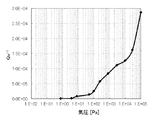
図23は、Qv−1と気圧との関係を検討に用いた振動素子2の形状および大きさを示す平面図である。図24は、Qv−1と気圧との関係を示すグラフである。図25は、等価直列抵抗値R1と気圧との関係を示すグラフである。
Hereinafter, it will be proved that the above-described effect can be exhibited when the atmospheric pressure in the
FIG. 23 is a plan view showing the shape and size of the
図24に示すグラフの横軸は、圧力[Pa]を示し、縦軸は、Qv−1(空気抵抗のみを考慮したQ値の逆数)を示している。図25に示すグラフの横軸は、圧力[Pa]を示し、縦軸は、CI値(R1)[kΩ]を示している。
本検討は、図23に示すような振動素子2を用い、この振動素子2をパッケージ9内に収容した振動子1を用いた。
The horizontal axis of the graph shown in FIG. 24 indicates pressure [Pa], and the vertical axis indicates Qv −1 (reciprocal of Q value considering only air resistance). The horizontal axis of the graph shown in FIG. 25 indicates the pressure [Pa], and the vertical axis indicates the CI value (R1) [kΩ].
In this examination, a vibrating
本検討に用いた振動素子2の各寸法は以下のとおりである。水晶基板3の長手方向の長さ(水晶基板3’のY’方向の長さ)が、2200μmであり、水晶基板3の短手方向の長さ(基部4のX方向の長さ)が503μmである。また、第1基部41のY’方向の長さが286μmであり、第2基部42のY’方向の長さが145μmであり、連結部43の長さが237μmである。また、腕部50、60の長さ(Y’方向の長さ)が、それぞれ896μmであり、ハンマーヘッド59、69の長さ(Y’方向の長さ)が、それぞれ671μmである。また、ハンマーヘッド59と腕部50の境界部、およびハンマーヘッド69と腕部60の境界部の長さ(Y’方向の長さ)が、それぞれ52μmである。また、腕部50、60の幅(X方向の長さ)W1が、それぞれ130〜141μmであり、ハンマーヘッド59、69の幅(X方向の長さ)W2が、それぞれ215μmである。また、土手部の幅Wは、それぞれ、15〜30μmである。また、水晶基板3の厚さTは、120μmであり、溝55、56、65、66の深さは、それぞれ50μmである。また、電極形成領域551、561、651、661の長さ(Y’方向の長さ)が、610μmである。
The dimensions of the
なお、発見者らによって、振動素子2のサイズ(L、W、W1、W2、T)を変更しても、下記に示す結果と同等の傾向となることが確認されている。また、発見者らによって、電極未形成領域552、562、652、662を有しておらず、溝55、56、65、66の内面全体に励振電極が設けられている場合にであっても、下記に示す結果と同等の傾向となることが確認されている。
In addition, it has been confirmed by the discoverers that even if the size (L, W, W1, W2, T) of the
本検討では、次のようにして、パッケージ9内の気圧に対するQv−1を算出している。まず、パッケージ9内(収容空間A)の気圧を変更し、各気圧におけるQ(実測したQ値)を実測した。また、真空度が十分高い(気圧が十分低い)場合には、空気抵抗は、ほぼないものと考えられるため、この状態における空気抵抗による損失はないものとし、その際のQ値をQ0とした。すなわち、真空度を高くしていき、Q値が飽和したときのQ値をQ0(飽和したQ値)とした。したがって、Q(実測したQ値)と、Q0(飽和したQ値)とから、Qv(各気圧における空気抵抗のみを考慮したQ値)は、下記式(20)によって表すことができる。
Q−1=Qv−1+Q0 −1・・・(20)
式(20)中のQ−1はQ(実測したQ値)の逆数、Q0 −1はQ0(飽和したQ値)の逆数、Qv−1は(各気圧における空気抵抗のみを考慮したQ値)の逆数である。
In this examination, Qv −1 with respect to the atmospheric pressure in the
Q −1 = Qv −1 + Q 0 −1 (20)
In Formula (20), Q −1 is the reciprocal of Q (measured Q value), Q 0 −1 is the reciprocal of Q 0 (saturated Q value), and Qv −1 (considering only the air resistance at each atmospheric pressure) Q value).
なお、パッケージ9内(収容空間A)の気圧は、以下のようにして実測することができる。まず、真空チャンバー(図示せず)内に振動子1を入れ、振動子1のCI値を測定する。次に、振動子1のパッケージ9を開封して真空チャンバー内に振動子1を入れ、CI値を計測しながら、真空チャンバー内の真空度を上げていき、パッケージ9を開封する前に測定した振動子1のCI値と同じ値になったときの真空度を読み取る。このパッケージ9を開封した後の振動子1のCI値と、パッケージ9を開封する前の振動子1のCI値とからパッケージ9内の気圧を算出することができる。なお、表2に記載した本検討においては、振動子1のパッケージ9を開封した状態で真空チャンバー内に振動子1を入れ、真空チャンバー内の真空度を表2に記載した所定の気圧にした状態で、Q値を計測した。
表2に、各気圧[Pa]におけるQ(実測したQ値)、Qv(空気抵抗のみを考慮したQ値)、およびQv−1(空気抵抗のみを考慮したQ値の逆数)を示す。また、表2を基にして、各気圧[Pa]におけるQv−1をプロットしたものを図24に示す。
The air pressure in the package 9 (accommodating space A) can be measured as follows. First, the
Table 2 shows Q (measured Q value), Qv (Q value considering only air resistance), and Qv −1 (reciprocal of Q value considering only air resistance) at each atmospheric pressure [Pa]. Moreover, what plotted Qv- 1 in each atmospheric pressure [Pa] based on Table 2 is shown in FIG.
図24に示すグラフから分かるように、気圧が低く(真空度が高く)なるほどQv−1が小さくなっており、気圧が100[Pa]以下のとき、Qv−1が特に小さくなっていることが分かる。Qv−1は、Qv(各気圧における空気抵抗のみを考慮したQ値)の逆数であり、図24中のQv−1が低いほど、Q値の劣化を低減することができるといえる。したがって、図24のグラフから分かるように、パッケージ9内の気圧が100[Pa]以下であると、振動素子2に加わる空気抵抗をさらに小さくすることができ、Q値の更なる向上を図ることができることが証明された。
また、上記に記載した方法により、今度はパッケージ9内の気圧に対するCI値(R1)[kΩ]を計測した結果をプロットしたものを図25に示す。
As can be seen from the graph shown in FIG. 24, the lower the atmospheric pressure (the higher the degree of vacuum), the smaller Qv −1 . When the atmospheric pressure is 100 [Pa] or less, Qv −1 is particularly small. I understand. Qv −1 is the reciprocal of Qv (Q value considering only air resistance at each atmospheric pressure), and it can be said that the lower the Qv −1 in FIG. 24, the more the deterioration of the Q value can be reduced. Therefore, as can be seen from the graph of FIG. 24, when the atmospheric pressure in the
FIG. 25 shows a plot of the results of measuring the CI value (R1) [kΩ] against the atmospheric pressure in the
図25に示すグラフから、気圧が低く(真空度が高く)なるほど、R1が小さくなっており、気圧が100[Pa]以下のとき、R1が特に小さくなっている。特に、気圧が10[Pa]以下のとき、R1がさらに小さくなっていることが分かる。CI値(R1)は、振動素子2に加わる空気抵抗と対応しており、図25中のCI値(R1)が低いほど、Q値の劣化を低減することができるといえる。したがって、図25のグラフからも分かるように、パッケージ9内の気圧が100[Pa]以下であると、振動素子2に加わる空気抵抗をさらに小さくすることができ、Q値の更なる向上を図ることができることが証明された。特に、気圧が10[Pa]以下であると、振動素子2に加わる空気抵抗をさらに小さくできることができ、さらに気圧が1[Pa]以下であると、振動素子2に加わる空気抵抗をさらに小さくすることができ、最も好ましくは気圧が10−1[Pa]以下であると、振動素子2に加わる空気抵抗がさらに小さくすることができることが証明された。
また、図17のR1の値からパッケージ内の気圧の下限値としては7×10⁻⁴Paであれば十分であり、それ以上に気圧を低下させても、R1の値が飽和していることが観測された。従って、パッケージの封止工程おいては、気圧を7×10⁻⁴Paより低下させて真空度を上げていっても、時間的なロスと作業上のコストアップの要因になることが判明した。ゆえに、真空度の程度として、気圧の下限値は7×10⁻⁴Paであれば十分であることが分かった。
From the graph shown in FIG. 25, R1 is smaller as the atmospheric pressure is lower (the degree of vacuum is higher), and R1 is particularly smaller when the atmospheric pressure is 100 [Pa] or less. In particular, when the atmospheric pressure is 10 [Pa] or less, it can be seen that R1 is further reduced. The CI value (R1) corresponds to the air resistance applied to the
Further, from the value of R1 in FIG. 17, it is sufficient that the lower limit value of the atmospheric pressure in the package is 7 × 10 −4 Pa, and the value of R1 is saturated even if the atmospheric pressure is further reduced. Was observed. Therefore, in the package sealing process, it has been found that even if the air pressure is reduced to less than 7 × 10 −4 Pa and the degree of vacuum is increased, it causes a time loss and an increase in work cost. . Therefore, it was found that the lower limit of the atmospheric pressure was 7 × 10 −4 Pa as the degree of vacuum.
2.発振器
次いで、本発明の振動子を適用した発振器(本発明の発振器)について説明する。
図26は、本発明の発振器の一例を示す断面図である。
図26に示す発振器10は、振動素子2と、振動素子2を駆動するためのICチップ(チップ部品)80とを有している。以下、発振器10について、前述した振動子との相違点を中心に説明し、同様の事項については、その説明を省略する。
2. Oscillator Next, an oscillator to which the vibrator of the present invention is applied (the oscillator of the present invention) will be described.
FIG. 26 is a cross-sectional view showing an example of the oscillator of the present invention.
The
パッケージ9Aは、凹部911Aを有する箱状のベース91Aと、凹部911Aの開口を塞ぐ板状のリッド92とを有している。
ベース91Aの凹部911Aには、段差部912Aが設けられている。
段差部912Aには、接続端子(図示せず)が形成されている。また、凹部911Aの底面(段差部912Aよりも底側の面)には、ICチップ80が配置されている。ICチップ80は、振動素子2の駆動を制御するための駆動回路(発振回路)を有している。ICチップ80によって振動素子2を駆動すると、所定の周波数の信号を取り出すことができる。
The
A
A connection terminal (not shown) is formed in the
また、凹部911Aの底面には、ワイヤーを介してICチップ80と電気的に接続された複数の内部端子(図示せず)が形成されている。これら複数の内部端子には、ベース91Aに形成された図示しないビアを介してパッケージ9Aの底面に形成された外部端子(図示せず)に電気的に接続された端子と、図示しないビアやワイヤーを介して接続端子(図示せず)に電気的に接続された端子とが含まれている。
なお、図26の構成では、ICチップ80が収容空間内に配置されている構成について説明したが、ICチップ80の配置は、特に限定されず、例えば、パッケージ9Aの外側(ベースの底面)に配置されていてもよい。
このような発振器10によれば、優れた信頼性を発揮することができる。
A plurality of internal terminals (not shown) electrically connected to the
In the configuration of FIG. 26, the configuration in which the
Such an
3.電子機器
次いで、本発明の振動子を適用した電子機器(本発明の電子機器)について、図27〜図29に基づき、詳細に説明する。
図27は、本発明の振動子を備える電子機器を適用したモバイル型(またはノート型)のパーソナルコンピューターの構成を示す斜視図である。この図において、パーソナルコンピューター1100は、キーボード1102を備えた本体部1104と、表示部100を備えた表示ユニット1106とにより構成され、表示ユニット1106は、本体部1104に対しヒンジ構造部を介して回動可能に支持されている。このようなパーソナルコンピューター1100には、フィルター、共振器、基準クロック等として機能する振動子1が内蔵されている。
3. Electronic Device Next, an electronic device (electronic device of the present invention) to which the vibrator of the present invention is applied will be described in detail with reference to FIGS.
FIG. 27 is a perspective view illustrating a configuration of a mobile (or notebook) personal computer to which an electronic device including the vibrator according to the invention is applied. In this figure, a
図28は、本発明の振動子を備える電子機器を適用した携帯電話機(PHSも含む)の構成を示す斜視図である。この図において、携帯電話機1200は、複数の操作ボタン1202、受話口1204および送話口1206を備え、操作ボタン1202と受話口1204との間には、表示部100が配置されている。このような携帯電話機1200には、フィルター、共振器等として機能する振動子1が内蔵されている。
FIG. 28 is a perspective view showing a configuration of a mobile phone (including PHS) to which an electronic device including the vibrator of the present invention is applied. In this figure, a
図29は、本発明の振動子を備える電子機器を適用したディジタルスチルカメラの構成を示す斜視図である。なお、この図には、外部機器との接続についても簡易的に示されている。ここで、通常のカメラは、被写体の光像により銀塩写真フィルムを感光するのに対し、ディジタルスチルカメラ1300は、被写体の光像をCCD(Charge Coupled Device)などの撮像素子により光電変換して撮像信号(画像信号)を生成する。
FIG. 29 is a perspective view showing a configuration of a digital still camera to which an electronic apparatus including the vibrator according to the invention is applied. In this figure, connection with an external device is also simply shown. Here, an ordinary camera sensitizes a silver halide photographic film with a light image of a subject, whereas a
ディジタルスチルカメラ1300におけるケース(ボディー)1302の背面には、表示部が設けられ、CCDによる撮像信号に基づいて表示を行う構成になっており、表示部は、被写体を電子画像として表示するファインダとして機能する。また、ケース1302の正面側(図中裏面側)には、光学レンズ(撮像光学系)やCCDなどを含む受光ユニット1304が設けられている。
A display unit is provided on the back of a case (body) 1302 in the
撮影者が表示部に表示された被写体像を確認し、シャッターボタン1306を押下すると、その時点におけるCCDの撮像信号が、メモリー1308に転送・格納される。また、このディジタルスチルカメラ1300においては、ケース1302の側面に、ビデオ信号出力端子1312と、データ通信用の入出力端子1314とが設けられている。そして、図示されるように、ビデオ信号出力端子1312にはテレビモニター1430が、デ−タ通信用の入出力端子1314にはパーソナルコンピューター1440が、それぞれ必要に応じて接続される。さらに、所定の操作により、メモリー1308に格納された撮像信号が、テレビモニター1430や、パーソナルコンピューター1440に出力される構成になっている。このようなディジタルスチルカメラ1300には、フィルター、共振器等として機能する振動子1が内蔵されている。
When the photographer confirms the subject image displayed on the display unit and presses the
なお、本発明の振動子を備える電子機器は、図27のパーソナルコンピューター(モバイル型パーソナルコンピューター)、図28の携帯電話機、図29のディジタルスチルカメラの他にも、例えば、インクジェット式吐出装置(例えばインクジェットプリンター)、ラップトップ型パーソナルコンピューター、テレビ、ビデオカメラ、ビデオテープレコーダー、カーナビゲーション装置、ページャー、電子手帳(通信機能付も含む)、電子辞書、電卓、電子ゲーム機器、ワードプロセッサー、ワークステーション、テレビ電話、防犯用テレビモニター、電子双眼鏡、POS端末、医療機器(例えば電子体温計、血圧計、血糖計、心電図計測装置、超音波診断装置、電子内視鏡)、魚群探知機、各種測定機器、計器類(例えば、車両、航空機、船舶の計器類)、フライトシュミレーター等に適用することができる。 In addition to the personal computer (mobile personal computer) shown in FIG. 27, the mobile phone shown in FIG. 28, and the digital still camera shown in FIG. Inkjet printers), laptop personal computers, televisions, video cameras, video tape recorders, car navigation devices, pagers, electronic notebooks (including those with communication functions), electronic dictionaries, calculators, electronic game devices, word processors, workstations, televisions Telephone, crime prevention TV monitor, electronic binoculars, POS terminal, medical equipment (for example, electronic thermometer, blood pressure monitor, blood glucose meter, electrocardiogram measuring device, ultrasonic diagnostic device, electronic endoscope), fish detector, various measuring devices, instruments Class (eg, vehicle, aircraft) Gauges of a ship), can be applied to a flight simulator or the like.
4.移動体
次いで、本発明の振動子を適用した移動体について、図30に基づき、詳細に説明する。
図30は、本発明の振動子を備える電子機器を適用した移動体(自動車)の構成を示す斜視図である。この図において、移動体1500は、車体1501と、4つの車輪1502とを有しており、車体1501に設けられた図示しない動力源(エンジン)によって車輪1502を回転させるように構成されている。このような移動体1500には、発振器10(振動素子2)が内蔵されている。
このような電子機器によれば、優れた信頼性を発揮することができる。
なお、発明の振動素子を備える移動体は、自動車に限定されず、例えば、オートバイ、鉄道等の他の車両、航空機、船舶、宇宙船等にも適用可能である。
4). Next, a moving body to which the vibrator of the present invention is applied will be described in detail with reference to FIG.
FIG. 30 is a perspective view illustrating a configuration of a moving body (automobile) to which an electronic device including the vibrator according to the invention is applied. In this figure, a moving
According to such an electronic device, excellent reliability can be exhibited.
Note that the moving body including the vibration element according to the invention is not limited to an automobile, and can be applied to, for example, other vehicles such as motorcycles and railways, aircrafts, ships, and space ships.
以上、本発明の振動子、発振器、電子機器および移動体について図示の実施形態に基づいて説明したが、本発明は、これに限定されるものではなく、各部の構成は、同様の機能を有する任意の構成のものに置換することができる。また、本発明に、他の任意の構成物が付加されていてもよい。また、各実施形態を適宜組み合わせてもよい。
また、振動素子としては、発振器に限定されず、例えば、ジャイロセンサーのようなセンサーにも適用することができる。
As mentioned above, although the vibrator | oscillator, the oscillator, the electronic device, and the moving body of this invention were demonstrated based on embodiment of illustration, this invention is not limited to this, The structure of each part has the same function. Any configuration can be substituted. In addition, any other component may be added to the present invention. Moreover, you may combine each embodiment suitably.
Further, the vibration element is not limited to an oscillator, and can be applied to a sensor such as a gyro sensor, for example.
また、前記実施形態では、水晶を用いた振動素子について説明したが、振動素子は水晶を用いたものに限定されず、Si、チタン酸バリウム、チタン酸鉛、チタン酸ジルコン酸鉛(PZT:Pb(Zr,Ti)O3)、ニオブ酸リチウム、タンタル酸リチウム等を用いたものでもよい。また更に、屈曲振動の駆動方式も圧電駆動型に限定されず、静電駆動型であっても良いことは言うまでもない。 Moreover, although the vibration element using quartz was demonstrated in the said embodiment, a vibration element is not limited to what uses quartz, Si, barium titanate, lead titanate, lead zirconate titanate (PZT: Pb) (Zr, Ti) O 3 ), lithium niobate, lithium tantalate, or the like may be used. Furthermore, the bending vibration driving method is not limited to the piezoelectric driving type, and it goes without saying that it may be an electrostatic driving type.
1‥‥振動子 2‥‥振動素子 3‥‥水晶基板 4‥‥基部 5‥‥振動腕 6‥‥振動腕 9‥‥パッケージ 9A‥‥パッケージ 10‥‥発振器 11‥‥導電性接着剤 41‥‥第1基部 42‥‥第2基部 43‥‥連結部 59、69‥‥ハンマーヘッド 55、56、65、66‥‥溝 51、52‥‥主面 53、54‥‥側面 50、60‥‥腕部 61、62‥‥主面 63、63‥‥側面 51a、51b、52a、53b‥‥土手部 80‥‥ICチップ 84‥‥第1駆動用電極 85‥‥第2駆動用電極 91‥‥ベース 91A‥‥ベース 92‥‥リッド 100‥‥表示部 151‥‥弾性棒 152‥‥弾性棒 154‥‥回転体 155‥‥回転軸 156‥‥回転体 157‥‥回転軸 158‥‥連結部(第1の連結部) 159‥‥連結部(第2の連結部) 160‥‥連結部(第3の連結部) 167‥‥基部 168‥‥基部 169‥‥第4の連結部 411‥‥縮幅部 551、561、651、661‥‥電極形成領域 552、562、652、662‥‥電極未形成領域 911‥‥凹部 911A‥‥凹部 912‥‥段差部 912A‥‥段差部 951、961‥‥接続端子 1100‥‥パーソナルコンピューター 1102‥‥キーボード 1104‥‥本体部 1106‥‥表示ユニット 1200‥‥携帯電話機 1202‥‥操作ボタン 1204‥‥受話口 1206‥‥送話口 1300‥‥ディジタルスチルカメラ 1302‥‥ケース 1304‥‥受光ユニット 1306‥‥シャッターボタン 1308‥‥メモリー 1312‥‥ビデオ信号出力端子 1314‥‥入出力端子 1430‥‥テレビモニター 1440‥‥パーソナルコンピューター 1500‥‥移動体 1501‥‥車体 1502‥‥車輪 AA‥‥領域 A‥‥収容空間 S、S1、S2‥‥領域
DESCRIPTION OF
Claims (10)
前記パッケージ内に収容され、屈曲振動モードで振動する振動素子と、
を含み、
前記パッケージ内の気圧は、100Pa以下であることを特徴とする振動子。 Package and
A vibration element housed in the package and vibrating in a flexural vibration mode;
Including
An air pressure in the package is 100 Pa or less.
基部と、
前記基部から延出されている一対の振動腕と、
を含む請求項1ないし3のうちのいずれか1項に記載の振動子。 The vibrating element is
The base,
A pair of vibrating arms extending from the base;
The vibrator according to claim 1, comprising:
錘部と、
前記錘部と前記基部との間に設けられている腕部と、を含む請求項1ないし4のうちのいずれか1項に記載の振動子。 The vibrating arm is
A weight part;
The vibrator according to any one of claims 1 to 4, further comprising an arm portion provided between the weight portion and the base portion.
前記錘部の前記第1方向に沿った長さをHとしたとき、
0.183≦H/L≦0.597
なる関係を満足している請求項1ないし5のうちのいずれか1項に記載の振動子。 The vibrating arm has a length along the first direction of the vibrating arm as L,
When the length along the first direction of the weight portion is H,
0.183 ≦ H / L ≦ 0.597
The vibrator according to claim 1, wherein the following relationship is satisfied.
前記錘部の前記第1の方向に沿った長さをHとしたとき、
0.012<H/L<0.30
なる関係を満足している請求項1ないし5のうちのいずれか1項に記載の振動子。 The vibrating arm has a length along the first direction of the vibrating arm as L,
When the length of the weight portion along the first direction is H,
0.012 <H / L <0.30
The vibrator according to claim 1, wherein the following relationship is satisfied.
回路と、
を備えていることを特徴とする発振器。 The vibrator according to any one of claims 1 to 7,
Circuit,
An oscillator comprising:
Priority Applications (4)
| Application Number | Priority Date | Filing Date | Title |
|---|---|---|---|
| JP2013237480A JP2015097368A (en) | 2013-11-16 | 2013-11-16 | Vibrator, oscillator, electronic apparatus and movable body |
| TW103139441A TWI634742B (en) | 2013-11-16 | 2014-11-13 | Resonator blank, resonator, oscillator, electronic apparatus, and mobile object |
| US14/541,759 US9628046B2 (en) | 2013-11-16 | 2014-11-14 | Resonator element, resonator, oscillator, electronic apparatus, and mobile object |
| CN201410646261.0A CN104660207B (en) | 2013-11-16 | 2014-11-14 | Vibrating reed, oscillator, oscillator, electronic equipment and moving body |
Applications Claiming Priority (1)
| Application Number | Priority Date | Filing Date | Title |
|---|---|---|---|
| JP2013237480A JP2015097368A (en) | 2013-11-16 | 2013-11-16 | Vibrator, oscillator, electronic apparatus and movable body |
Publications (2)
| Publication Number | Publication Date |
|---|---|
| JP2015097368A true JP2015097368A (en) | 2015-05-21 |
| JP2015097368A5 JP2015097368A5 (en) | 2016-12-28 |
Family
ID=53374469
Family Applications (1)
| Application Number | Title | Priority Date | Filing Date |
|---|---|---|---|
| JP2013237480A Pending JP2015097368A (en) | 2013-11-16 | 2013-11-16 | Vibrator, oscillator, electronic apparatus and movable body |
Country Status (1)
| Country | Link |
|---|---|
| JP (1) | JP2015097368A (en) |
Cited By (2)
| Publication number | Priority date | Publication date | Assignee | Title |
|---|---|---|---|---|
| JP2018165633A (en) * | 2017-03-28 | 2018-10-25 | セイコーエプソン株式会社 | Sensor element, sensor, electronic apparatus, and movable body |
| CN112207014A (en) * | 2019-07-09 | 2021-01-12 | 精工爱普生株式会社 | Resonator element, resonator, electronic apparatus, and moving object |
Citations (5)
| Publication number | Priority date | Publication date | Assignee | Title |
|---|---|---|---|---|
| JP2006196932A (en) * | 2003-05-07 | 2006-07-27 | Seiko Epson Corp | Tuning fork type piezoelectric device and method of manufacturing same |
| JP2009253622A (en) * | 2008-04-04 | 2009-10-29 | Nippon Dempa Kogyo Co Ltd | Tuning-fork piezoelectric vibrator, and piezoelectric device |
| JP2011250225A (en) * | 2010-05-28 | 2011-12-08 | Nippon Dempa Kogyo Co Ltd | Piezoelectric device and method for adjusting frequency thereof |
| JP2012044235A (en) * | 2010-08-12 | 2012-03-01 | Seiko Epson Corp | Piezoelectric device and electronic apparatus |
| JP2012129904A (en) * | 2010-12-17 | 2012-07-05 | Seiko Epson Corp | Electronic apparatus |
-
2013
- 2013-11-16 JP JP2013237480A patent/JP2015097368A/en active Pending
Patent Citations (5)
| Publication number | Priority date | Publication date | Assignee | Title |
|---|---|---|---|---|
| JP2006196932A (en) * | 2003-05-07 | 2006-07-27 | Seiko Epson Corp | Tuning fork type piezoelectric device and method of manufacturing same |
| JP2009253622A (en) * | 2008-04-04 | 2009-10-29 | Nippon Dempa Kogyo Co Ltd | Tuning-fork piezoelectric vibrator, and piezoelectric device |
| JP2011250225A (en) * | 2010-05-28 | 2011-12-08 | Nippon Dempa Kogyo Co Ltd | Piezoelectric device and method for adjusting frequency thereof |
| JP2012044235A (en) * | 2010-08-12 | 2012-03-01 | Seiko Epson Corp | Piezoelectric device and electronic apparatus |
| JP2012129904A (en) * | 2010-12-17 | 2012-07-05 | Seiko Epson Corp | Electronic apparatus |
Cited By (2)
| Publication number | Priority date | Publication date | Assignee | Title |
|---|---|---|---|---|
| JP2018165633A (en) * | 2017-03-28 | 2018-10-25 | セイコーエプソン株式会社 | Sensor element, sensor, electronic apparatus, and movable body |
| CN112207014A (en) * | 2019-07-09 | 2021-01-12 | 精工爱普生株式会社 | Resonator element, resonator, electronic apparatus, and moving object |
Similar Documents
| Publication | Publication Date | Title |
|---|---|---|
| JP6107333B2 (en) | Vibrator, oscillator, electronic device, and moving object | |
| JP5910287B2 (en) | Vibrating piece, vibrator, oscillator and electronic equipment | |
| JP6349622B2 (en) | Vibration element, vibrator, oscillator, electronic device, and moving object | |
| CN108183698B (en) | Resonator element, resonator, oscillator, electronic apparatus, sensor, and moving object | |
| KR20140118840A (en) | Vibrating element, vibrator, oscillator, electronic apparatus, and moving object | |
| JP6281254B2 (en) | Vibration element, vibrator, oscillator, electronic device, and moving object | |
| JP6209886B2 (en) | Vibrating piece, vibrator, oscillator, electronic device and moving object | |
| JP2014200051A (en) | Vibration element, vibrator, oscillator, electronic device, and mobile unit | |
| JP6375622B2 (en) | Vibrating piece, vibrator, oscillator, electronic device, sensor and moving body | |
| TW201526542A (en) | Vibration element, vibrator, oscillator, electronic apparatus, and moving object | |
| JP6287208B2 (en) | Vibrators, oscillators, electronic devices, physical quantity sensors, and moving objects | |
| JP2014200050A (en) | Vibration element, vibrator, oscillator, electronic device, and mobile unit | |
| JP2015149591A (en) | Oscillation element, transducer, oscillator, electronic apparatus, sensor and mobile object | |
| JP2015023422A (en) | Vibration piece, vibrator, oscillator, electronic apparatus and mobile | |
| JP2015097368A (en) | Vibrator, oscillator, electronic apparatus and movable body | |
| JP2015149592A (en) | Vibration element, vibrator, oscillator, electronic device, and mobile unit | |
| JP2015002556A (en) | Vibration piece, vibrator, oscillator, electronic device, and mobile unit | |
| JP7439852B2 (en) | Vibrating elements, vibrators, oscillators, electronic equipment, and moving objects | |
| JP6521148B2 (en) | Vibrating element, vibrator, oscillator, electronic device and moving body | |
| JP6340774B2 (en) | Vibration element, vibrator, oscillator, electronic device, and moving object | |
| JP2014107603A (en) | Vibration piece, vibrator, oscillator, and electronic apparatus | |
| JP6816805B2 (en) | Vibrating elements, oscillators, oscillators, electronic devices and mobiles | |
| JP6614227B2 (en) | Vibration element, vibrator, oscillator, electronic device, and moving object | |
| JP2019115079A (en) | Vibration element, vibrator, oscillator, electronic apparatus, and mobile body | |
| JP2018061286A (en) | Vibration element, vibrator, oscillator, electronic apparatus, and movable body |
Legal Events
| Date | Code | Title | Description |
|---|---|---|---|
| A521 | Request for written amendment filed |
Free format text: JAPANESE INTERMEDIATE CODE: A523 Effective date: 20161115 |
|
| A621 | Written request for application examination |
Free format text: JAPANESE INTERMEDIATE CODE: A621 Effective date: 20161115 |
|
| A977 | Report on retrieval |
Free format text: JAPANESE INTERMEDIATE CODE: A971007 Effective date: 20171031 |
|
| A131 | Notification of reasons for refusal |
Free format text: JAPANESE INTERMEDIATE CODE: A131 Effective date: 20171121 |
|
| A521 | Request for written amendment filed |
Free format text: JAPANESE INTERMEDIATE CODE: A523 Effective date: 20180118 |
|
| A02 | Decision of refusal |
Free format text: JAPANESE INTERMEDIATE CODE: A02 Effective date: 20180619 |