JP6275407B2 - Container lock - Google Patents
Container lock Download PDFInfo
- Publication number
- JP6275407B2 JP6275407B2 JP2013155001A JP2013155001A JP6275407B2 JP 6275407 B2 JP6275407 B2 JP 6275407B2 JP 2013155001 A JP2013155001 A JP 2013155001A JP 2013155001 A JP2013155001 A JP 2013155001A JP 6275407 B2 JP6275407 B2 JP 6275407B2
- Authority
- JP
- Japan
- Prior art keywords
- lock
- hook
- locking device
- container
- drive member
- Prior art date
- Legal status (The legal status is an assumption and is not a legal conclusion. Google has not performed a legal analysis and makes no representation as to the accuracy of the status listed.)
- Active
Links
- 230000007246 mechanism Effects 0.000 claims description 148
- 230000005484 gravity Effects 0.000 claims description 13
- 230000000694 effects Effects 0.000 description 8
- 230000000903 blocking effect Effects 0.000 description 6
- 230000006835 compression Effects 0.000 description 6
- 238000007906 compression Methods 0.000 description 6
- 238000009434 installation Methods 0.000 description 5
- 238000000034 method Methods 0.000 description 4
- 230000008569 process Effects 0.000 description 4
- 230000000452 restraining effect Effects 0.000 description 4
- 230000004048 modification Effects 0.000 description 3
- 238000012986 modification Methods 0.000 description 3
- 230000008901 benefit Effects 0.000 description 2
- 238000004519 manufacturing process Methods 0.000 description 2
- 235000001674 Agaricus brunnescens Nutrition 0.000 description 1
- 230000009471 action Effects 0.000 description 1
- 238000003780 insertion Methods 0.000 description 1
- 230000037431 insertion Effects 0.000 description 1
- 238000011900 installation process Methods 0.000 description 1
- 238000012423 maintenance Methods 0.000 description 1
- 238000003825 pressing Methods 0.000 description 1
- 230000008439 repair process Effects 0.000 description 1
- 230000000284 resting effect Effects 0.000 description 1
Images


Classifications
-
- E—FIXED CONSTRUCTIONS
- E05—LOCKS; KEYS; WINDOW OR DOOR FITTINGS; SAFES
- E05C—BOLTS OR FASTENING DEVICES FOR WINGS, SPECIALLY FOR DOORS OR WINDOWS
- E05C19/00—Other devices specially designed for securing wings, e.g. with suction cups
- E05C19/10—Hook fastenings; Fastenings in which a link engages a fixed hook-like member
- E05C19/12—Hook fastenings; Fastenings in which a link engages a fixed hook-like member pivotally mounted around an axis
-
- B—PERFORMING OPERATIONS; TRANSPORTING
- B60—VEHICLES IN GENERAL
- B60P—VEHICLES ADAPTED FOR LOAD TRANSPORTATION OR TO TRANSPORT, TO CARRY, OR TO COMPRISE SPECIAL LOADS OR OBJECTS
- B60P7/00—Securing or covering of load on vehicles
- B60P7/06—Securing of load
- B60P7/13—Securing freight containers or forwarding containers on vehicles
- B60P7/132—Securing freight containers or forwarding containers on vehicles twist-locks for containers or frames
-
- E—FIXED CONSTRUCTIONS
- E05—LOCKS; KEYS; WINDOW OR DOOR FITTINGS; SAFES
- E05B—LOCKS; ACCESSORIES THEREFOR; HANDCUFFS
- E05B9/00—Lock casings or latch-mechanism casings ; Fastening locks or fasteners or parts thereof to the wing
-
- Y—GENERAL TAGGING OF NEW TECHNOLOGICAL DEVELOPMENTS; GENERAL TAGGING OF CROSS-SECTIONAL TECHNOLOGIES SPANNING OVER SEVERAL SECTIONS OF THE IPC; TECHNICAL SUBJECTS COVERED BY FORMER USPC CROSS-REFERENCE ART COLLECTIONS [XRACs] AND DIGESTS
- Y10—TECHNICAL SUBJECTS COVERED BY FORMER USPC
- Y10T—TECHNICAL SUBJECTS COVERED BY FORMER US CLASSIFICATION
- Y10T292/00—Closure fasteners
- Y10T292/08—Bolts
- Y10T292/0911—Hooked end
- Y10T292/0936—Spring retracted
-
- Y—GENERAL TAGGING OF NEW TECHNOLOGICAL DEVELOPMENTS; GENERAL TAGGING OF CROSS-SECTIONAL TECHNOLOGIES SPANNING OVER SEVERAL SECTIONS OF THE IPC; TECHNICAL SUBJECTS COVERED BY FORMER USPC CROSS-REFERENCE ART COLLECTIONS [XRACs] AND DIGESTS
- Y10—TECHNICAL SUBJECTS COVERED BY FORMER USPC
- Y10T—TECHNICAL SUBJECTS COVERED BY FORMER US CLASSIFICATION
- Y10T292/00—Closure fasteners
- Y10T292/08—Bolts
- Y10T292/0911—Hooked end
- Y10T292/0945—Operating means
- Y10T292/0947—Cam
-
- Y—GENERAL TAGGING OF NEW TECHNOLOGICAL DEVELOPMENTS; GENERAL TAGGING OF CROSS-SECTIONAL TECHNOLOGIES SPANNING OVER SEVERAL SECTIONS OF THE IPC; TECHNICAL SUBJECTS COVERED BY FORMER USPC CROSS-REFERENCE ART COLLECTIONS [XRACs] AND DIGESTS
- Y10—TECHNICAL SUBJECTS COVERED BY FORMER USPC
- Y10T—TECHNICAL SUBJECTS COVERED BY FORMER US CLASSIFICATION
- Y10T292/00—Closure fasteners
- Y10T292/62—Bolt casings
Description
本発明は、請求項1の序文に記載のコンテナのためのロック装置と、コンテナロックハウジングと、コンテナロックボックスと、複数のロック装置の構成とに関わる。 The invention relates to a locking device for a container, a container lock housing, a container lock box and a plurality of locking devices according to the preamble of claim 1.
コンテナの輸送は、上にコンテナが簡易的かつ安全な方法で固定されなければならない道路輸送車によって、度々行われる。このために、このような輸送車は、前記コンテナのコーナー取着部材と共働する適切なロック装置を有する。 Container transportation is often carried out by road vehicles on which the container must be secured in a simple and safe manner. For this purpose, such a transport vehicle has a suitable locking device which cooperates with the corner mounting member of the container.
ロックピンとマッシュルーム型ヘッドとを有するいわゆるツイストロックが、一般に使用されている。このロックピンは、前記コーナー取着部材中に導入され、ねじられ、そして、ロック位置に留められる。このようなロック装置は、例えば、特許文献1によって知られている。このような装置は、手動で操作されなければならないという欠点を有している。 A so-called twist lock having a lock pin and a mushroom type head is generally used. The lock pin is introduced into the corner mounting member, twisted and held in the locked position. Such a locking device is known, for example, from US Pat. Such a device has the disadvantage that it must be operated manually.
特許文献2は、ロック位置のブロックによるローディングの間の自動のロックと、アンローディングプロセスの前にブロック手段が解除される半自動のアンローディングと、を可能にするロック装置を開示している。この装置は、ハサミのような構成で、垂直方向に移動する共通の軸を中心として、反対方向に回動し得る1つ、もしくは特に2つのロックレバーを有している。この軸の下で、前記ロックレバーの下側の脚部が、上側の脚部に対して曲げられ、そして曲げられたレバーが、前記下側の脚部のヒンジによって、回動される。この曲げられたレバーは、前記ロック装置のハウジング中の固定点で回動し得る。更に、摺動するバーの形態のブロック手段が、ロック装置の前記ハウジング中に配設される。前記バーは、これのロック位置の方向に、ばねによって付勢される。コンテナが所定の位置に置かれている時にリリースを押し下げると、前記バーのロックが解除され、この結果、張り詰められた圧縮ばねによって、前記バーがはじけ出て、前記ハサミのヒンジの共通の軸の垂直運動を妨げ、かくしてこれをブロックする。 U.S. Pat. No. 6,053,077 discloses a locking device that allows automatic locking during loading with a block in the locked position and semi-automatic unloading where the blocking means is released before the unloading process. This device has a scissor-like configuration and has one or especially two lock levers that can be pivoted in opposite directions around a common axis moving in the vertical direction. Under this axis, the lower leg of the lock lever is bent with respect to the upper leg, and the bent lever is rotated by the hinge of the lower leg. This bent lever can pivot at a fixed point in the housing of the locking device. Furthermore, blocking means in the form of sliding bars are arranged in the housing of the locking device. The bar is biased by a spring in the direction of its locked position. When the release is pushed down when the container is in place, the bar is unlocked and, as a result, the tensioned compression spring causes the bar to pop out and a common axis of the scissors hinge. Hinder the vertical movement of and thus block this.
この装置は、前記曲がっているレバー及びハサミの機構が扱いにくく、かくして製造に費用がかかり、うまく動作しない傾向がある。更に、前記ロックレバーは、ロック位置でブロックされているだけで、クランプされていない。この結果、前記コーナー取着部材は、動作の間に振動し得、コンテナの頑丈な設置が、保証され得ない。 This device tends to be cumbersome to the bent lever and scissor mechanism and thus expensive to manufacture and tend to fail. Furthermore, the lock lever is only blocked in the locked position and is not clamped. As a result, the corner attachment member can vibrate during operation and a sturdy installation of the container cannot be guaranteed.
ホックのようなロック装置に関するこの問題を解決するために、単一のロックフックのみを設け、前記ハウジング中の静止の回動軸を中心として回動し得る第1種のレバーとしてこのフックを構成することが、すでに提案されている。前記ロックフックの下側の端部と係合するシャフトによって、前記ロックフックは、道具によって、及び手動で、ロック位置に配置され得、ひとたび前記コーナー取着部材に係合すると、このコーナー取着部材が下方向に押され得る。この装置は、このロック位置に自動的に降下しないことと、前記シャフトの回動から前記フックのロック、クランプ、アンロックまで、時間がかかることとの欠点を有している。 In order to solve this problem relating to a locking device such as a hook, only a single lock hook is provided, and this hook is configured as a first type lever that can rotate around a stationary rotation axis in the housing. It has already been proposed. By means of a shaft that engages the lower end of the lock hook, the lock hook can be placed in the locked position by means of a tool and manually, once this corner attachment member is engaged. The member can be pushed downward. This device has the disadvantages of not being automatically lowered to this locked position and taking time from pivoting the shaft to locking, clamping and unlocking the hook.
本発明の目的は、簡潔な構造を有し、自動でロックし、コンテナの頑丈な設置を確実にするコンテナロック装置を提供することである。 The object of the present invention is to provide a container locking device which has a simple structure, locks automatically and ensures a robust installation of the container.
この目的は、請求項1の特徴によって果たされる。 This object is fulfilled by the features of claim 1.
本発明は、フック本体と、フック部材と、回動軸とを有し、コンテナロックハウジングに対して静止の軸を中心としてスタンバイ位置とロック位置とに回動し得る、ロックフックに基づく。単一のロックフックが、ロック装置の単純な構造と、前記ハウジング中での単純な構成とを可能にする。 The present invention is based on a lock hook having a hook body, a hook member, and a rotation shaft, and capable of rotating between a standby position and a lock position about a stationary shaft with respect to a container lock housing. A single locking hook enables a simple structure of the locking device and a simple configuration in the housing.
前記ロックフックは、1つ、2つ、もしくは2つ以上の部品を有し得る。複数の部品から成る場合、2つ以上の細い部品が、ロックフックとして、即ち細い幅を有するロックフックとして形成されている。前記部品の全幅は、好ましくはワンピースのロックフックの幅に対応する。複数の部品から成る場合に、前記ロックフックの個々の部品の前記フック部材は、同じ方向に向いており、前記ロックフックの前記部品は、同じ方向に、同じ静止の回動軸を中心として、一緒に回動する。 The lock hook may have one, two, or two or more parts. In the case of a plurality of parts, two or more thin parts are formed as a lock hook, that is, as a lock hook having a narrow width. The total width of the part preferably corresponds to the width of the one-piece lock hook. In the case of a plurality of parts, the hook members of the individual parts of the lock hook are oriented in the same direction, and the parts of the lock hook are centered on the same stationary rotation axis in the same direction, Rotate together.
複数の部品から成る構成の前記ロックフックは、費用が減じられ得るので、製造において利点を有する。更に、部品の故障による機能の全停止の危険が、ロックフックの種々のデザインによって、減じられる。 The lock hook, which consists of a plurality of parts, has advantages in manufacturing because the cost can be reduced. In addition, the risk of total outage due to component failure is reduced by the various designs of the lock hook.
駆動機構が、ブロック、リリースなどのように前記ロックフックを駆動させるために必要な部品を有する。前記駆動機構は、第1の駆動部材と、第2の駆動部材と、リリース機構とを有している。 The drive mechanism has parts necessary for driving the lock hook, such as a block and a release. The drive mechanism includes a first drive member, a second drive member, and a release mechanism.
2つの個々の駆動部材を設けて、一方には前記ロックフックのスタンバイ位置、もう一方には前記ロックフックのロック位置に割り当てることによって、これら駆動部材が異なる任務にそれぞれ適合され得る、という利点を有する。 By providing two individual drive members, one assigned to the standby position of the lock hook and the other to the lock position of the lock hook, the drive members can be adapted to different missions, respectively. Have.
前記第1の駆動部材は、前記ロックフックをスタンバイ位置に保持するように構成されている。この保持は、移動し得ないように固定して、スタンバイ位置にブロックすることを含む。 The first driving member is configured to hold the lock hook in a standby position. This holding includes fixing it so that it cannot move and blocking it in the standby position.
重心の配置に基づいてスタンバイ位置からロック位置に重力で降下するロックフックに関しては、前記第1の駆動部材は、重力に対抗し、前記ロック位置への望ましくない回動を防ぐために十分である。 For a lock hook that descends by gravity from a standby position to a locked position based on the center of gravity arrangement, the first drive member is sufficient to resist gravity and prevent undesired rotation to the locked position.
第2の駆動部材が、前記ロックフックを、ロック位置にブロックするだけでなくクランプするように、構成されている。このことによって、前記ロック装置へのコンテナの設置が緩むことによって生じるがたつきを防ぎ、前記コンテナの頑丈な設置を確実にする。 A second drive member is configured to clamp as well as block the lock hook in the locked position. This prevents rattling caused by loose installation of the container on the locking device and ensures a sturdy installation of the container.
前記リリース機構は、前記コンテナによって駆動され得ることが、好ましい。前記リリース機構は、前記コンテナが積載面上に置かれる時に、前記ロックフックのブロックとクランプとが、前記リリース機構と前記第1の駆動部材及び/もしくは前記第2の駆動部材との相互作用によって自動で、即ち手動の介入を必要とせずに行われるように、特にそれぞれのコンテナ取着部材によって駆動される。 It is preferred that the release mechanism can be driven by the container. The release mechanism is configured such that when the container is placed on the loading surface, the block and the clamp of the lock hook are interacted with the release mechanism and the first drive member and / or the second drive member. In particular, it is driven by the respective container attachment member so that it takes place automatically, i.e. without the need for manual intervention.
第1の構成の変形例に従えば、前記リリース機構が、前記第1の駆動部材と係合し得る。この場合、前記第1の駆動部材は、好ましくは前記第2の駆動部材に作用し、もしくは、前記第1の駆動部材は、前記第2の駆動部材に好ましくは結合されるか、これに接して配設される。 According to a modification of the first configuration, the release mechanism can engage with the first drive member. In this case, the first drive member preferably acts on the second drive member, or the first drive member is preferably coupled to or in contact with the second drive member. Arranged.
第2の構成の変形例に従えば、前記リリース機構が、前記第2の駆動部材と係合し得る。この場合、前記第2の駆動部材は、好ましくは前記第1の駆動部材に作用し、もしくは、前記第2の駆動部材は、前記第1の駆動部材に好ましくは結合されるか、これに接して配設される。 According to a modification of the second configuration, the release mechanism can engage with the second drive member. In this case, the second drive member preferably acts on the first drive member, or the second drive member is preferably coupled to or in contact with the first drive member. Arranged.
前記第1及び第2の駆動部材は、接続部材によって好ましくは互いに結合される。 The first and second drive members are preferably coupled together by a connection member.
第3の構成の変形例に従えば、前記第第1及び第2の駆動部材は、互いに完全に独立して動作し得る。この場合、前記リリース機構は、好ましくは前記駆動部材の両方に作用する。 According to a modification of the third configuration, the first and second drive members can operate completely independently of each other. In this case, the release mechanism preferably acts on both of the drive members.
前記第1の駆動部材は、前記第1の駆動部材が前記ロックフックをスタンバイ位置に保持している状態である時に、前記第1の駆動部材がばね付勢されるように、第1のばね機構を有している。 The first drive member includes a first spring so that the first drive member is spring-biased when the first drive member is holding the lock hook in a standby position. It has a mechanism.
前記リリース機構が駆動されている時に前記第2の駆動部材が前記第1の駆動部材の前記ばね機構の力に対抗して作用し、前記ロックフックへの作用を相殺するように、前記駆動部材、もしくはこれら駆動部材に作用する力が、互いに調和され得る。 The drive member so that the second drive member acts against the force of the spring mechanism of the first drive member and cancels the action on the lock hook when the release mechanism is driven. Alternatively, the forces acting on these drive members can be harmonized with each other.
前記リリース機構のリリースは、前記ロックフックのスタンバイ位置を自動的にリリースし、この結果、ロック位置へと移動し得る、という効果を有する。従って、前記第1の駆動部材は、リリース位置及び保持位置に好ましくは移動し得、これの保持位置では、前記フックをスタンバイ位置に保持する。前記第1の駆動部材の、これの保持位置からの自動の移動が、前記第2の駆動部材との結合がなされているかどうかに関わる。 Release of the release mechanism has the effect that it automatically releases the standby position of the lock hook and consequently can move to the lock position. Accordingly, the first drive member can preferably move to the release position and the holding position, where the hook is held in the standby position. The automatic movement of the first drive member from its holding position is related to whether or not the second drive member is coupled.
好ましくは、前記第1の駆動部材は、特に前記第2の駆動部材の自動の移動が前記第1の駆動部材の自動の移動を生じさせるように配設されている前記第2の駆動部材に、結合している。 Preferably, the first drive member is in particular the second drive member arranged such that the automatic movement of the second drive member causes the automatic movement of the first drive member. , Have joined.
前記第1の駆動部材は、好ましくはばね部材である。これは、前記ロックフックが、スタンバイ位置でクランプされ、かくして、例えば、前記ロックフックの制限のない遊び、もしくはぐらつきが防がれる、という効果を有する。 The first drive member is preferably a spring member. This has the effect that the lock hook is clamped in the standby position, thus preventing, for example, unrestricted play or wobble of the lock hook.
前記第2の駆動部材は、休止位置及びブロック位置に、好ましくは移動し得る。自動の連続移動を生じさせるために、好ましくは第2のばね機構が設けられており、この第2のばね機構は、前記リリース機構のリリースの後に、前記第2の駆動部材をクランプ位置へと引っ張り、このクランプ位置では、前記第2の駆動部材は、前記ロックフックをロック位置にブロックし、クランプする。 The second drive member can preferably move to a rest position and a block position. In order to cause automatic continuous movement, a second spring mechanism is preferably provided, which after the release mechanism is released, moves the second drive member to the clamping position. Pulling and in this clamping position, the second drive member blocks and clamps the locking hook in the locking position.
前記ロックフックのリリースは、好ましくは操作機構によって、半自動式に行われる。この操作機構は、以下に説明される。 The release of the lock hook is preferably carried out semi-automatically by an operating mechanism. This operating mechanism will be described below.
好ましくは、前記ロックフックは、回動軸が第1の端部に設けられているレバーであり、これに対して、前記フック部材は、前記レバーの第2の端部に配置されている。このようなロックレバーの力関係が、前記回動軸が前記レバーの端部間に配置されている第一種のレバーの場合より、都合がよい。他の効果は、前記回動軸が前記ハウジング中の下側に配置され得、このハウジングが前記回動支持部を収容するためにより多くの可能性を開くことである。前記回動支持部は、前記ハウジングの1つの壁に好ましくは配設されており、好ましくは、前記回動支持部は、前記ハウジングの後ろ側の壁に設けられている。 Preferably, the lock hook is a lever having a rotation shaft provided at the first end, whereas the hook member is disposed at the second end of the lever. Such a force relationship of the lock lever is more convenient than the case of the first type lever in which the rotation shaft is disposed between the end portions of the lever. Another effect is that the pivot shaft can be arranged on the lower side in the housing, which opens up more possibilities for accommodating the pivot support. The rotation support portion is preferably disposed on one wall of the housing, and preferably the rotation support portion is provided on a rear wall of the housing.
好ましくは、前記ロックフックは、前記第1の端部と前記第2の端部との間に駆動手段を有している。この配置は、両駆動部材が前記駆動手段に係合し得る、という効果を有する。前記ロックフックのスタンバイ位置では、前記第1の駆動部材は、前記駆動手段の下側のところに好ましくは係合し、前記ロックフックの前記ブロック位置では、前記第2の駆動部材は、前記駆動手段の上側のところに好ましくは係合する。 Preferably, the lock hook has a driving means between the first end and the second end. This arrangement has the effect that both drive members can engage the drive means. In the standby position of the lock hook, the first drive member is preferably engaged below the drive means, and in the block position of the lock hook, the second drive member is the drive. The upper part of the means is preferably engaged.
好ましくは、前記駆動手段は、前記回動軸に平行して配置されている棒状部材である。 Preferably, the drive means is a rod-like member disposed in parallel with the rotation shaft.
前記棒状部材は、前記フック本体の一体部分であり得る。また、前記棒状部材は、前記フック本体にねじ込まれることが可能である。 The rod-shaped member may be an integral part of the hook body. The rod-shaped member can be screwed into the hook body.
前記レバーの好ましい一実施形態は、所定の角度で傾斜されて配置されている脚部を有する前記フック本体を有し、前記フック部材は、前記第1の脚部の自由端部に配設され、前記回動軸は、前記第2の脚部の自由端部に配設されている。好ましくは、前記駆動手段は、前記脚部の接続領域に配設されている。 A preferred embodiment of the lever includes the hook body having a leg portion that is inclined at a predetermined angle, and the hook member is disposed at a free end portion of the first leg portion. The rotation shaft is disposed at the free end of the second leg. Preferably, the driving means is disposed in a connection region of the leg portion.
前記レバーの湾曲した構造は、前記レバーの力が最適化され得る、という効果を有するだけでなく、前記ハウジング内での前記回動軸の位置と前記駆動手段の位置とが、前記ハウジング内の空間状態に対して適合され且つ最適化され得る、という効果を有している。 The curved structure of the lever not only has the effect that the lever force can be optimized, but also the position of the pivot shaft and the position of the drive means in the housing It has the effect that it can be adapted and optimized for spatial conditions.
好ましくは、前記ロックフックは、前記ハウジングの設置された状態で、前記ロック位置へと、重力によって降下する。前記ロックレバーは、端部に回動軸を有するレバーであるので、前記回動軸からの重心の距離が大きく、この結果、前記第1の駆動部材によるスタンバイ位置のリリース時から、前記ロックフックが、重力によって、かくして自動的にブロック位置へと降下するために、接続のラインに対して、垂直方向からわずかに傾いていればよい。 Preferably, the lock hook is lowered by gravity to the lock position in a state where the housing is installed. Since the lock lever is a lever having a pivot shaft at the end, the distance of the center of gravity from the pivot shaft is large. As a result, the lock hook is released from the standby position released by the first drive member. However, in order to automatically descend to the block position by gravity, it is only necessary to tilt slightly from the vertical direction with respect to the connecting line.
前記ロックフックがスタンバイ位置でばね機構によってばね付勢されることが、好ましくはロックフックの効果であり得る。前記ロック位置への回動は、このようにして支持され得、即ち完全に行われ得る。このことは、前記ロック装置が、ロック装置が上に配置されている積載面の傾斜状態によって斜面して、前記ロックフックをロック位置に降下させるために更なる力が必要とされる程度に方向づけられている場合に、有効であり得る。 It can be preferably the effect of the lock hook that the lock hook is spring biased by a spring mechanism in the standby position. The pivoting to the locked position can be supported in this way, i.e. completely performed. This is oriented to the extent that the locking device is inclined due to the inclined state of the loading surface on which the locking device is arranged and further force is required to lower the locking hook to the locked position. May be effective if
好ましくは、前記第2の駆動部材は、前記ロックフックと直接にもしくは間接に係合し且つ前記ロックフックをクランプするカム面を有している。 Preferably, the second drive member has a cam surface that engages the lock hook directly or indirectly and clamps the lock hook.
カム面は、湾曲した面であり得、例えば所定の半径を有しているか、自由な形状の面である。また、カム面は、2つ以上の平坦な表面部分を有する面であり得る。また、カム面は、少なくとも1つの湾曲した面と少なくとも1つの平坦な面との組み合わせであり得る。 The cam surface may be a curved surface, for example, having a predetermined radius or a free-form surface. In addition, the cam surface may be a surface having two or more flat surface portions. The cam surface can also be a combination of at least one curved surface and at least one flat surface.
好ましくは、前記カム面は、前記ロックフックのパワーロッククランプ及びブロックのための、少なくとも1つの部分を有している。 Preferably, the cam surface has at least one portion for a power lock clamp and block of the lock hook.
この部分は、好ましくは、斜面であり、前記第2の駆動部材の直進運動の時に、前記ロックフックの駆動手段を横切って延び、前進運動するのに従って、前記駆動手段を押圧し、かくして、前記ロックフックを、例えば前記ロック装置の設置位置へと、更に降下させる。このことによって、前記フックが既に前記取着部材に当接している場合、前記取着部材と、かくしてコンテナとのクランプが生じる。 This part is preferably a bevel, extending across the drive means of the lock hook during the rectilinear movement of the second drive member and pressing the drive means as it moves forward, thus the said The lock hook is further lowered, for example, to the installation position of the lock device. This causes clamping of the attachment member and thus the container when the hook is already in contact with the attachment member.
例えば回動運動のような前記第2の駆動部材の種々の連続運動の場合、前記部分は、違った方法で適切に構成され得る。 In the case of various continuous movements of the second drive member, such as for example a pivoting movement, the part can be configured appropriately in different ways.
前記カム面の部分は、前記第2の駆動部材のブロック位置への連続した移動の際に前記駆動手段への力が強まるように、好ましくは構成されている。 The portion of the cam surface is preferably configured so that the force on the drive means is increased during the continuous movement of the second drive member to the block position.
好ましくは、前記カム面は、前記ロックフックの適切なブロックのための少なくとも1つの部分を有している。この部分は、前記第2の駆動部材の移動方向でのブロックとクランプとのために、前記部分の前に好ましくは配置され、この結果、クランプが意図せずリリースされても、前記ロックフックのブロックが、依然として確実になされる。 Preferably, the cam surface has at least one part for a suitable block of the locking hook. This part is preferably arranged in front of the part for blocking and clamping in the direction of movement of the second drive member, so that even if the clamp is unintentionally released, the locking hook Blocking is still reliably done.
好ましくは、前記第2の駆動部分は、休止位置及びブロック位置への直進運動によって移動し得るバーである。前記直進運動は、ブロック及びクランプのために、及びブロックだけのために、前記部分の簡潔な構造を可能にする。これら部分は、まっすぐな、もしくは平坦な面として、構成され得る。 Preferably, the second drive part is a bar that can be moved by a rectilinear movement to a rest position and a block position. The rectilinear movement allows a simple structure of the part for blocks and clamps and for blocks only. These portions can be configured as straight or flat surfaces.
好ましくは、前記バーは楔形状である。 Preferably, the bar is wedge shaped.
好ましくは、2つのバーが互いに並んで配置されており、接続部材によって互いに接続されている。前記第2の駆動部材のこの実施形態は、1つのバーが故障した場合、もしくは1つのバーが最適にクランプされない場合に、全停止を生じさせない、という効果を有している。 Preferably, the two bars are arranged side by side and are connected to each other by a connecting member. This embodiment of the second drive member has the effect of not causing a full stop if one bar fails or if one bar is not optimally clamped.
好ましくは、前記第2の駆動部材が移動可能に中に取り付けられている前記ハウジング中に、案内機構が、設けられている。 Preferably, a guide mechanism is provided in the housing in which the second drive member is movably mounted.
前記第2の駆動部材は、前記休止位置で、好ましくは第2のばね機構によって、プレテンションされている。 The second drive member is pretensioned in the rest position, preferably by a second spring mechanism.
好ましくは、前記第2の駆動部材は、移動止め部材によって、第1の休止位置で拘束され得る。前記リリース機構のリリースの後に、この拘束がリリースされ、前記第2の駆動部材が、前記第2のばね機構によって、前記ブロック位置に移動される。前記ばね機構の力は、前記湾曲面による十分なクランプが可能となるように、好ましくは調節される。従って、前記ばね機構と前記カム面とは、互いに適合される。 Preferably, the second drive member can be restrained at the first rest position by a detent member. After the release mechanism is released, the constraint is released, and the second driving member is moved to the block position by the second spring mechanism. The force of the spring mechanism is preferably adjusted so that sufficient clamping by the curved surface is possible. Therefore, the spring mechanism and the cam surface are adapted to each other.
好ましくは、前記移動止め部材は、前記第2の駆動部材をリリースするために、前記リリース機構によって、駆動され得る。 Preferably, the detent member may be driven by the release mechanism to release the second drive member.
他の実施形態に従えば、前記第2の駆動部材は、ラチェットによって第2の休止位置で保持される。前記ラチェットは、前記操作機構によってアンロックがなされる場合に使用されるが、前記コンテナは前記ロック装置から取り外されない。このことは、前記操作機構と共に、より詳細に説明される。 According to another embodiment, the second drive member is held in a second rest position by a ratchet. The ratchet is used when unlocked by the operating mechanism, but the container is not removed from the locking device. This will be explained in more detail together with the operating mechanism.
好ましくは、前記ラチェットは、回動され、重力もしくはばね駆動によってブロック位置へと降下する。前記ラチェットは、好ましくは前記ハウジングに固定されて回動される。 Preferably, the ratchet is rotated and lowered to the block position by gravity or spring drive. The ratchet is preferably fixed to the housing and rotated.
ブロック位置では、前記ラチェットは、前記第2の駆動部材の凹部に好ましくは係合する。 In the block position, the ratchet preferably engages a recess in the second drive member.
好ましくは、前記ラチェットは、手動で動かされ得、外側からアンロック位置へとアクセス可能であり得る。前記第2の駆動部材が休止位置へと手動で移動され、この結果前記ロックフックがスタンバイ位置にあるが前記コンテナがまだ取り外されていない状態である時に、前記リリース機構は、リリースされた状態にとどまる。このアンロックを取り消す必要がある場合、前記ラチェットをリリース位置に手動で移動させる必要がある。 Preferably, the ratchet can be moved manually and accessible to the unlocked position from the outside. The release mechanism is released when the second drive member is manually moved to the rest position so that the lock hook is in the standby position but the container has not yet been removed. Stay. When it is necessary to cancel this unlocking, it is necessary to manually move the ratchet to the release position.
この後に、前記第2の駆動部材は、前記第2のばね機構によって、ブロック位置へと移動され得る。 After this, the second drive member can be moved to the block position by the second spring mechanism.
好ましくは、前記ラチェットは、前記リリース機構によって、駆動され得る。前記リリース機構が前記リリース位置に移動されている時、前記ラチェットは、リリース位置へと移動される。 Preferably, the ratchet can be driven by the release mechanism. When the release mechanism is moved to the release position, the ratchet is moved to the release position.
好ましくは、操作機構が、前記第1の駆動部材及び/もしくは前記第2の駆動部材のために設けられており、前記操作機構には、第3のばね機構が好ましくは設けられている。前記ロックフックのアンロックは、好ましくは半自動式の前記操作機構によって果たされる。休止位置からアンロック位置へと手動で引っ張られる前記操作機構を使用することによって、前記第2の駆動部材は、前記ブロック位置から前記休止位置へと好ましくは移動され、この結果、前記ロックフックは、前記スタンバイ位置へと自動的に移動される。前記第2の駆動部材は、休止位置で取着される。この後に、前記操作機構は、前記第3のばね機構によって、休止位置へと自動的に引き戻される。 Preferably, an operating mechanism is provided for the first driving member and / or the second driving member, and the operating mechanism is preferably provided with a third spring mechanism. The unlocking of the locking hook is preferably accomplished by the semi-automatic operating mechanism. By using the operating mechanism that is manually pulled from the rest position to the unlock position, the second drive member is preferably moved from the block position to the rest position, so that the lock hook is And automatically moved to the standby position. The second drive member is attached at a rest position. Thereafter, the operation mechanism is automatically pulled back to the rest position by the third spring mechanism.
前記操作機構は、前記ハウジングの前記上壁に好ましくは平行に配置され得る。好ましくは、前記操作機構は、少なくとも1つの案内トラックもしくはスライドを有しており、前記操作機構は、このような案内トラックもしくはスライドを使用して、前記第2の駆動部材に移動可能に配置され、前記案内トラックの端部は、前記第2の駆動部材に沿って駆動するように当接部を形成する。 The operating mechanism may be arranged preferably parallel to the upper wall of the housing. Preferably, the operation mechanism has at least one guide track or slide, and the operation mechanism is movably disposed on the second drive member using the guide track or slide. The end portion of the guide track forms a contact portion so as to be driven along the second driving member.
好ましくは、前記第3のばね機構は、前記操作機構を、休止位置で保持する。 Preferably, the third spring mechanism holds the operation mechanism at a rest position.
好ましくは、前記リリース機構は、リリースピンを有している。これについて、リリースピンのための開口部が、前記ハウジングの壁の1つに、好ましくは設けられている。前記リリースピンは、係合が外されたリリース位置と、係合された位置とに、移動され得る。 Preferably, the release mechanism has a release pin. In this regard, an opening for the release pin is preferably provided in one of the walls of the housing. The release pin may be moved to a released release position and an engaged position.
前記リリースピンは、第1のばね装置によって、リリース位置でプレテンションされる。 The release pin is pretensioned in the release position by a first spring device.
前記コンテナが前記ロック装置に配置されている時、前記リリースピンは、前記ばねの力に対抗して移動され、リリースプロセスが行われる。 When the container is placed in the locking device, the release pin is moved against the spring force and the release process takes place.
好ましくは、ロックフックが係合されているかどうかをユーザーに知らせるロック表示機構が、前記ハウジングの壁の1つに設けられている。 Preferably, a lock indicator mechanism is provided on one of the housing walls to inform the user whether the lock hook is engaged.
前記ロック表示機構は、ハウジングの壁を通って外側に延びている、プレテンションされたピンを、好ましくは有している。 The lock indicator mechanism preferably includes a pretensioned pin that extends outward through the wall of the housing.
前記ロック表示機構は、前記第1もしくは第2の駆動部材によって、直接に、もしくは間接に、好ましくは駆動される。 The lock display mechanism is preferably driven directly or indirectly by the first or second driving member.
好ましくは、前記ロックフックが側面に設けられている2つの突出している案内部材が、前記ハウジングの前記上壁に配置されている。このことは、前記取着部材へのコンテナの挿入を容易にし、前記ロックフックをダメージから保護する。前記案内部材は、前記ロックフックを超えて好ましくは突出している。 Preferably, two protruding guide members, on which the lock hooks are provided on the side surfaces, are arranged on the upper wall of the housing. This facilitates insertion of the container into the attachment member and protects the lock hook from damage. The guide member preferably projects beyond the lock hook.
前記ばね部材は、ブリッジにわたる自由端部の所で、好ましくは互いに接続され得る。前記ブリッジは、好ましくは、前記取着部材の開口部中への導入を容易にする円錐形状、もしくはピラミッド形状である。 The spring members may preferably be connected to each other at the free end across the bridge. The bridge is preferably conical or pyramidal to facilitate introduction into the opening of the attachment member.
好ましくは、前記駆動機構は、前記ハウジング中に挿入され得るボックス中に配設されている。このボックスによって、前記駆動機構全体が、取り出され得る。前記ロックフックと可能であれば前記ロック表示機構とのみが、前記ハウジング中に依然として配設されている。かくして、前記駆動機構へのメンテナンス及び修理作業が、前記ハウジングから取り出されたボックスで、容易になされ得る。 Preferably, the drive mechanism is disposed in a box that can be inserted into the housing. With this box, the entire drive mechanism can be removed. Only the lock hook and possibly the lock indicator mechanism are still arranged in the housing. Thus, maintenance and repair work on the drive mechanism can be easily performed with the box removed from the housing.
少なくとも1つの上壁と、2つの側壁と、後壁と、前記上壁を通って延びているロックフックとを有するコンテナロックボックスを収容する前記コンテナロックハウジングであって、前記ロックフックは、フック本体と、フック部材と、前記コンテナロックハウジングに対して静止でありこれを中心としてスタンバイ位置とロック位置とに回動し得る回動軸と、を有する、コンテナロックハウジングにおいて、前記ロックフックの前記回動軸は、前記上壁に平行に配置されており、回動支持部が、前記ロックフックの回動による取り付けのために、ハウジングの壁の1つに設けられていることを特徴とする。 A container lock housing containing a container lock box having at least one upper wall, two side walls, a rear wall, and a lock hook extending through the upper wall, the lock hook being a hook A container lock housing, comprising: a main body; a hook member; and a pivot shaft that is stationary with respect to the container lock housing and pivotable about a standby position and a lock position about the container lock housing. The rotation shaft is arranged in parallel with the upper wall, and a rotation support portion is provided on one of the walls of the housing for mounting by rotation of the lock hook. .
前記コンテナロックハウジングに使用するための前記コンテナロックボックスは、3つのサブアセンブリが設けられておりロックフックのための駆動機構を形成している取り付けプレートを有していることを特徴とし、第1のサブアセンブリは、第1のばね機構を有するリリース機構を有しており、第2のアセンブリは、前記第2のばね機構を有する前記取り付けプレートと平行に移動し得る第1の駆動部材と第2の駆動部材とを有しており、第3のサブアセンブリは、第3のばね機構を有する前記第1の及び/もしくは第2の駆動部材のための操作機構を有している。 The container lock box for use in the container lock housing has a mounting plate provided with three subassemblies and forming a drive mechanism for the lock hook, The subassembly includes a release mechanism having a first spring mechanism, and the second assembly includes a first drive member movable in parallel with the mounting plate having the second spring mechanism, and a first drive member. And the third subassembly has an operating mechanism for the first and / or second drive member having a third spring mechanism.
コンテナ積載面へのロック装置の配置が、対向した対を成すように、前記積載面の端部に前記ロック装置を配置することを求め、各々の対の装置の前記フック部材は、反対の方向を向いている。 It is required to arrange the locking device at the end of the loading surface so that the arrangement of the locking device on the container loading surface forms an opposing pair, and the hook members of each pair of devices are in opposite directions Facing.
このような配置は、前記それぞれのフックの位置が、前記コンテナがロードされた時に外側から運転手によって認識され得、カーブを曲がる時に前記コンテナに作用する遠心力が、良好に吸収され得る。 With such an arrangement, the position of the respective hooks can be recognized by the driver from the outside when the container is loaded, and the centrifugal force acting on the container when turning a curve can be well absorbed.
本発明の例としての実施形態が、図面を用いて、下に詳細に説明される。 Exemplary embodiments of the invention are described in detail below with the aid of the drawings.
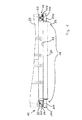
図1は、コンテナ20が積載面32に配置されているセミトレーラ30の後ろ側の部分的な図であり、前記コンテナ20のコーナー取着部材22が、断面図で示されている。
FIG. 1 is a partial view of a rear side of a
前記トレーラ30に互いに対向して配置されている2つのロック装置10が、一対のロック装置12を形成している。各ロック装置10は、ロックフック110を有するコンテナロックハウジング100を有している。前記コンテナロックハウジング100中には、前記ロックフック110のための、他の図を参照してより詳細に説明される駆動機構210が、配置されている。
Two
前記ロックフック110は、それぞれの前記コーナー取着部材22と係合し、この時、フック部材111が、前記コーナー取着部材22の底部23のロック面24を押圧する。前記ロックフック110のクランプによって、前記コンテナ20が、頑丈に保持され、垂直方向の遊びがなくなる。
The lock hooks 110 engage with the respective
前記ロック装置10は、一対の前記ロック装置12の前記フック部材111がそれぞれ外側に、かくして互いに反対方向を向くように、配置されている。図示されている配置は、コンテナが積載されている時に、それぞれの前記フックの位置が外側から運転手に認識され得ることと、カーブを走行中に前記コンテナに作用する遠心力が良好に吸収され得ることと、の利点を有する。
The locking
一対のフック装置12の両方が、内側に向くように配置されることも、可能である。
It is also possible that both of the pair of
前記ロック装置10は、図2乃至図17で、第1の見本の実施形態(いわゆるボックスの変形例)によって、ここに説明される。この実施形態は、2つの構成部材から成っており、即ち、前記ロックフック110を有する前記コンテナロックハウジング100と、前記ロックフック110のための全駆動機構210を収容しているコンテナロックボックスとから成っている。このコンテナロックボックス200は、スライドイン部品として構成されており、あらかじめ取り付けられている引き出しのようなユニットとして、ロック装置10の前記コンテナロックハウジング100中に押し込まれ得る。前記コンテナロックボックス200は、前記コンテナロックハウジング100から引き出されることによって、取り外され得る。
The locking
前記コンテナロックハウジング100は、上壁102と、2つの側壁104、106と、後壁108と、底壁109とを有している。これらの壁は、完全に閉じられる必要はない。前記側壁104には、前記ロックフック110のロック位置を知らせるロック表示機構160が、設けられている。この機構160は、ピン164を有しており、このピン164は、ロックされていない位置では、前記側壁104の開口部162を通って外側に突出している。ロックされている位置では、前記ピン164は、ひっこんでおり、前記側壁104と同一平面である。
The
前記上壁102は、前記ロックフック110が中を通って上方に延びている開口部170を有している。ここに示されている実施形態では、前記ロックフック110は、2つの部品110’から成っている。従って、前記ロックフック110は、2つのフック部材部分111’から成るフック部材111を有している。
The
前記ロックフック110は、前記コーナー取着部材22中に導入されやすいように、突出した2つの案内部材152、154が、側面に配置されている。前記2つの案内部材152、154は、丸みを帯びた構造であり且つ前記コンテナ10の前記コーナー取着部材22中への導入を同様に容易にするブリッジ156によって、互いに接続されている。同時に、前記ブリッジ156は、前記コーナー取着部材22中に導入される時のダメージに対して、前記ロックフック110を保護する。
The protruding two
前記コンテナロックボックス200は、取り付けプレート202を有しており、この上に、前記ロックフック110のための前記駆動機構210の種々のサブアセンブリ220、250、330が、取着されている。
The
前記取り付けプレート202には、正面プレート204が取着されている。この正面プレート204に示されているハンドル350が、他の図面を参照してより詳細に説明される、第2の駆動部材260のための操作機構332に属している。
A
前記コンテナロックハウジング100に取り付けられる前記駆動機構210を必要とする第2の他の実施形態は、取り付けプレート202が設けられておらず、前記駆動機構210が前記ハウジングの壁に取り付けられている、という点で、異なっている。この場合の前記正面プレート204は、前記コンテナロックハウジング100の前壁を形成しており、例えば前記ハウジングの壁104、106に、取り付けられる。
A second alternative embodiment requiring the
前記駆動機構210と、駆動機構210の構成部材と、駆動機構210の、前記ロックフック110に関連した機能とに関する見解が、他の実施形態の両方に、同様に当てはまる。
The views regarding the
図2では、前記駆動機構210の構成部材の多くが、隠れている。前記コンテナロックボックス200の左側には、緊張ばね342の形態の第3のばね機構340が設けられており、これは、第3のサブアセンブリ330の前記操作機構332の一部分である。前記緊張ばね342は、前記取り付けプレート202と前記ハンドル350とに、取着されている(図14も参照)。更に、第2のばね機構280が、緊張ばね282の形態で設けられており、これは、前記第2の駆動部材260が属している第2のサブアセンブリ250の一部分である。前記緊張ばね282は、前記取り付けプレート202と前記第2の駆動部材260とに取着されている(図14も参照)。前記コンテナロックボックス200の右側には、2つの前記緊張ばね342、282(図6参照)が、設けられている。これら緊張ばね342、282は、図2では見えない。
In FIG. 2, many of the structural members of the
前記第2の他の実施形態の場合では、前記緊張ばね282、342が、前記ハウジング100の後壁108に、取着されている。
In the case of the second alternative embodiment, the tension springs 282, 342 are attached to the
前記取り付けプレート202を通って、リリース機構221のリリースピン222が上方向に延びており、このリリースピン222は、図3に示されているように、前記コンテナロックハウジング100中に配置された後に、前記上壁102の開口部150を通って上方に突出している。図3は、前記コンテナロックボックス200が前記コンテナロックハウジング100に挿入されている状態のロック装置10を、示している。
Through the mounting
前記第2の他の実施形態では、図3に示されている前記正面プレート204は、前記ハウジングの壁102、104、106に取着されている。
In the second alternative embodiment, the
図4には、フック本体112とフック部材111とを有する前記ロックフック110が、斜視図で示されている。前記ロックフック110は、2つのフック部分110’と2つのフック部材部分111’とを有するツーピースのフックであり、2つの端部136、138を有するレバーとして構成されている。この第1の端部136には、前記フック部材111が設けられており、第2の端部138には、回動軸114が設けられている。前記2つの端部136、138間には、棒状部材134として構成されている駆動手段132が、設けられている。ここに示されている実施形態では、この駆動手段132は、前記ロックフック110に、ねじによって取り付けられている。前記棒状部材134は、前記フック本体112に対して側方に突出しており、かくして、2つの軸139a、139bを形成している。前記軸139a、139bは、ベアリング、例えばボールベアリング(図示されていない)に、更に取着されている。
FIG. 4 is a perspective view of the
前記駆動手段132は、第1の駆動部材290と第2の駆動部材260と共に動作する。前記第1の駆動部材290は、前記軸139a、139bの下側に係合しており(図10、図11参照)、前記第2の駆動部材260は、前記軸139a、139bの上側に係合している(図13参照)。
The driving
前記レバーは湾曲している。このレバーは、前記レバーの端部136、138とそれぞれ一体である自由端118、122をそれぞれ有する第1の脚部116と第2の脚部120とを有している。前記2つの脚部116、120の接続領域130には、前記駆動手段132が、配設されている。前記第2の脚部120は、2つの開口部142a、142bを有しており、これら開口部142a、142bを通って前記回動軸114が延び、またこれら開口部142a、142bは、回動支持部140とベアリングボルト144と一緒に、前記ロックフック110の回動支持部を形成している(図5参照)。
The lever is curved. The lever has a
前記ロックフック110の重心が、前記ロック装置10が設置された状態の前記ロックフックがスタンバイ位置からロック位置へと重力によって降下するように、前記回動軸114から一定の距離を空けて、配置されている。
The center of gravity of the
図5には、前記ロックフック110が取り付けられている前記コンテナロックハウジング100の底面図が、示されている。前記回動支持部140は、前記後壁108に固定されている。前記ベアリングボルト144によって、前記ロックフック110の前記第2の脚部120は、前記回動支持部140で回動するように、取り付けられている。
FIG. 5 shows a bottom view of the
図6には、第1、第2、第3のサブアセンブリ220、250、330の構成部材を有する前記コンテナロックボックス200の下側部分が、示されている。これら3つのサブアセンブリは、図7乃至図9に詳細に示されている。
FIG. 6 shows the lower part of the
前記第2のサブアセンブリ250は、2つの楔形状のバー262によって構成されている前記第2の駆動部材260を含む(図8aも参照)。前記2つのバー262は、接続部材264によって互いに接続されており、直線案内機構300中を、直進移動し得る。前記直線案内機構300は、溝306、308を有する2つの案内レール302、304を有している。これら案内レール302、304の各々に1つのバー262が、導かれる。前記第2の駆動部材260は、休止位置に配置されており、前記案内レール302、304に沿って、ブロック位置に移動し得る。
The
図6に示されている休止位置では、前記第2の駆動部材260は、拘束ブラケットの形態の移動止め部材240によって、保持されている(図7a、図7b参照)。前記移動止め部材240は、図7a、図7bに示されている前記第1のサブアセンブリ220の一部である。
In the rest position shown in FIG. 6, the
各バー262には、第2のばね機構280が係合されている締め付けピン279が設けられており、この第2のばね機構280は、プレテンションされており、前記第2の駆動部材260のリリースの後に、前記第2の駆動部材260を前記ブロック位置へと引っ張る。
Each
ばね部材として構成されている前記第1の駆動部材290は、前記第2の駆動部材260に固定されている。このばね部材は、ワイヤブラケットであり、図8aに詳細に示されている。
The
更に、前記第3のサブアセンブリ330の前記操作機構332の2つの案内プレート334が、図6に見られ、図9に詳細に示されている。これら案内プレート334は、長円の孔336の形態の、案内トラック335を有している。これら長円の孔336中には、前記第2の駆動部材260のねじ頭276、278が、導入される。このような案内プレート334は、前記ハンドル350に固定されており、前記第3のねじ機構340によって、プレテンションされている。
Further, two
図6の前記直線案内機構300は、前記取り付けプレート202に固定されている。第2の他の実施形態に従えば、前記取り付けプレート202は省かれており、従って、前記直線案内機構300は、前記上壁102に固定されている。
The
図7a、図7bには、前記第1のサブアセンブリ220が、2つの図に、拡大されて示されている。前記第1のサブアセンブリ220は、前記上壁102に、もしくは代わって前記取り付けプレート202に、配置されている。前記サブアセンブリ220は、前記リリースピン222を有する前記リリース機構221を有している。前記リリースピン222は、下側の端部に摺動案内部226を有しており、この摺動案内部226中には、前記移動止め部材240のピン244が、前記リリース機構221のリリース時に前記移動止め部材240が回動支持部242で回動し得且つリリースのための前記第2の駆動部材260を駆動させるように、導入されている。従って、前記移動止め部材240は、前記リリース機構221の締め付け部材238のところで回動し得る。
7a and 7b, the
前記リリース機構221は、2つの圧縮ばね232を有する第1のばね機構230を有している。これら圧縮ばね232の一方のみが、図示されている。前記圧縮ばね232は、突出したリリースの位置に、前記リリースピン222を保持している。
The release mechanism 221 includes a
図7bは、前記第1のサブアセンブリ220の他の図を示している。前記リリースピン222が駆動されることによって、ラチェット310が、前記第2の駆動部材260の凹部274中に、重力によって降下し得、かくして、前記リリースピン222の駆動にもかかわらず、これらを休止位置(第2の休止位置)に保持し得る。前記リリースピン222が、力から解放された時に、前記ラチェット310は、前記プレート224(図7a参照)によって、最初の位置に戻される。前記第2の駆動部材260は、かくして、前記ラチェット310によってリリースされ、もう一度回動している前記拘束ブラケット240まで摺動する。前記第2の駆動部材260は、かくして、前記リリースピン222が力から解放された時、前記休止位置(第1の休止位置)のままである。
FIG. 7 b shows another view of the
図8aは、拡大された前記第2のサブアセンブリ250を示している。
FIG. 8 a shows the enlarged
前記第2の駆動部材260の前記2つのバー262は、楔形状であり、第1の楔形状面266と、第2の楔形状面268とを有している。前記第1の楔形状面266には、図7bに示されているような前記ラチェット310が係合し且つ前記操作機構332に関連してより詳細に説明される凹部274が、設けられている。前記バー262の正面の端部には、前記移動止め部材240のためのエンドストップ284a、bが、設けられている。
The two
前記第2の楔形状面268は、図8bを参照して説明されるいくつかの部分を有している。前記2つのバー262の前記接続部材264に、前記第1の駆動部材290が、固定されている。この第1の駆動部材290は、2つの保持部分294を有しており、これら保持部分294は、接続部分292によって一緒に接続されている。前記保持部分294は、前記ロックフック110がスタンバイ位置にある時に、このロックフック110の前記駆動手段132に当接している(図10参照)。前記保持部分294は、2つのリリース部分296に隣接されており、これらリリース部分296によって、前記第1の駆動部材290が矢印の方向に移動している時に、前記ロックフック110がブロック位置に降下し得る(図13参照)。
The second wedge-shaped
この目的のために、前記2つのリリース部分296は、下方に曲げられており、前記ロックフック110の回動時に、前記駆動部材132のために必要な自由空間を形成している。
For this purpose, the two release portions 296 are bent downward to form a free space necessary for the
図8bは、斜視図で1つのバー262を示しており、この図は、3つの真直ぐで平らな部分を備えたカム面を有する前記第2の楔形状面268を、示している。
FIG. 8b shows one
セグメント271、272が、傾斜面として延びており、第1の楔形状面266に対して90°未満の角度αと角度βとをそれぞれ成している。角度βは、セルフブレーキが生じるように設定されている。これら2つのセグメント271、272の間には、前記楔形状の面266に対して平行なセグメント273がある。このセグメントは、前記ロックフック110のブロックに適した形状を提供する。前記セグメント271は、前記ロックフック110のパワーロックのブロック及びクランプを与え、前記セグメント272は、重力駆動の動作で前記ロックフックを支持し、且つ前記リリース部分296に対して平行に延びている。かくして、前記ロックフック110の前記駆動手段132は、前記第1の駆動部材290と前記第2の駆動部材260との間で、妨害されることなく、摺動し得る。
図9は、第3のサブアセンブリ330を示している。これは、操作機構332と第3のばね機構340とを有している。この操作機構332は、案内プレート334とハンドル350とによって構成されている。前記案内プレート334には、前記第2の駆動部材260に設けられているねじの前記ねじ頭276、278を受ける長円の孔336の形態で、スライドもしくは案内トラックが、設けられている。緊張ばね342によって、前記操作機構が、前記コンテナロックハウジング100中の休止位置へと引っ張られる。前記ハンドルが引き出された形態で駆動されている時、当接部分338が、前記ねじ頭276、278の2つに当接する(図14参照)。これは、第2の駆動部材260を同様に移動させる。前記スライドによって、前記第2の駆動部材260は、休止位置にある時、前記操作機構332から自由に移動し得る。
FIG. 9 shows a third subassembly 330. This has an operating mechanism 332 and a
前記ロック装置10の動作の仕方が、図10乃至図17を用いて、以下に説明される。
The manner of operation of the
図10は、開いている前記コンテナロックハウジング100とスタンバイ位置の前記ロックフック110との側面図であり、この図では、前記ロックフック110は、前記第1の駆動部材290によって保持されている。前記ロックフック110は、前記ブリッジ156の下で保護されている。前記第1の駆動部材290は、ワイヤブラケットとして構成されており、前記ロックフック110の駆動部材132を、保持部分294によって下から押圧する。前記第2の駆動部材260は、休止位置でプレテンションされており、前記エンドストップ284a、bに当接している前記移動止め部材240によって、保持されている(図8a参照)。前記リリースピン222は、リリース位置でプレテンションされる。
FIG. 10 is a side view of the
図11は、前記リリースピン222が前記圧縮ばね232の力に対抗して下方に押圧されるように、コーナー取着部材22を有する前記コンテナ20を位置づけている様子を示している。前記移動止め部材240は、上方に回動され、前記第2の駆動部材260は、リリースされる。前記緊張ばね282の力によって、前記第2の駆動部材260は、駆動手段132が前記第1の駆動部材290の保持部分294から離れるように矢印の方向に移動され、前記ロックフック110は、重力によって前記リリース部分296の領域に達する。このことによって、図12に示されているような、下方に向けられた移動(矢印参照)が可能となる。
FIG. 11 shows a state in which the container 20 having the
このプロセスで、前記2つのバー262の前記セグメント272は、前記駆動手段132に接触し、前記フック部材111が前記ブリッジ156の左下に現れるように、前記ロックフック110の下方の移動を援助する。
In this process, the
前記バー262は、図13に示されている状態に到達するまで、右方向に移動し続ける(矢印参照)。前記バー262の前記セグメント271によって、前記駆動手段132は、前記フック部材111が前記コーナー取着部材22の底部の前記ロック面24を押圧して前記コーナー取着部材22をクランプするように、下方にクランプされる。
The
前記コンテナロックハウジング100の外側へのばねの力に対して、前記接続部材264によってあらかじめいくらか押圧されている前記ロック表示機構160のピン164が、内側に摺動し得、前記ばねによって駆動されて、これによって、ロックを表示する(図2参照)。
The
アンロックのために、前記第3のサブアセンブリの前記操作機構332(図9参照)は、前記ハンドル350を前記案内プレート334と一緒に矢印の方向に引き出すことによって、手動で駆動される。このプロセスでは、前記ねじ頭276、278は、前記右側のねじ頭276が前記長円の孔226の端部に達するまで、前記案内プレート334の前記長円の孔336中を右方向に移動し、かくして当接部分338を成す。前記案内プレート334が更に引き出されると、前記第2の駆動部材260、例えば前記バー262が、これに沿って引っ張られる。前記ロックフック110は、リリースされ、同時に、図14乃至図16に示されているように、前記第1の駆動部材290によって、スタンバイ位置になるように持ちあげられる。
For unlocking, the operating mechanism 332 (see FIG. 9) of the third subassembly is driven manually by pulling the
この開かれている状態が、前記ピン164が前記接続部材264によって前記コンテナロックハウジング100の外側の方向にもう一度押圧されることによって、前記ロック表示機構160によって示される。
This open state is indicated by the
前記ハンドル350をリリースすると、前記操作機構322は、前記ハウジングの内側に摺動して戻る(図15参照)。前記第2の駆動部材260は、前記第1の駆動部材290の凹部274中に降下した前記ラチェット310によって、この状態に保持される(図17参照)。
When the
そして、前記コンテナ20は、持ち上げられ、取り外され得る。 The container 20 can then be lifted and removed.
図16は、前記アンロック位置を示しており、前記操作機構332を引き出すことによって、前記ロックフック110がスタンバイ位置に配置されている。しかしながら、これが無意図的になされた場合、例えば、そのあとの前記コンテナ20のアンローディングと取り外しとが予定されていない場合、前記ロックは、もう一度元に戻る。この目的のために、前記操作機構332が引き出された状態の前記ラチェット310が、図17の詳細図Xに示されているように、外側からアクセス可能であり得る。前記ラチェット310を手動で持ち上げることによって、前前記ラチェット310は、前記第2の駆動部材260をもう一度リリースする。前記第2の駆動部材260は、すでに説明した前記コンテナの設置のプロセスのように、前記駆動手段132によってもう一度摺動し、前記ロックを元に戻す。
FIG. 16 shows the unlock position. By pulling out the operation mechanism 332, the
前記コンテナ20は、開かれた前記ロックによって持ち上げられると、前記リリースピン222が、リリースされる。この後に、前記拘束ブラケット240は、下方に再度回動する。更に、前記ラチェット310は、前記第2の駆動部材260が前記拘束ブラケットの所まで摺動し得るように、前記プレート224によって最初の位置に押し戻される。そして、もう一度前記コンテナをロードするための用意ができている状態が、回復される。
When the container 20 is lifted by the opened lock, the
10…コンテナロック装置、12…一対のコンテナロック装置、20…コンテナ、22…コーナー取着部材、24…ロック面、30…セミトレーラ、32…積載面、100…コンテナロックハウジング、102…上壁、104、106…側壁、108…後壁、109…底壁、110…ロックフック、112…フック本体、114…回動軸、132…駆動手段、134…棒状部材、152、154…案内部材、156…ブリッジ、160…ロック表示機構、164…ピン、170…開口部、200…コンテナロックボックス、202…取り付けプレート、204…正面プレート、210…駆動機構、220…第1のサブアセンブリ、221…リリース機構、222…リリースピン、230…第1のばね機構、232…圧縮ばね、240…移動止め部材、242…回動点、250…第2のサブアセンブリ、260…第2の駆動部材、262…バー、270…カム面、276、278…ねじ頭、279…締め付けピン、280…第2のばね機構、282…緊張ばね、290…第1の駆動部材、300…直線案内機構、310…ラチェット、330…第3のサブアセンブリ、332…操作機構、340…第3のばね機構、342…緊張ばね、350…ハンドル
以下に、本願出願の当初の特許請求の範囲に記載された発明を付記する。
[1] コンテナロックハウジング(100)と、
フック本体(112)と、フック部材(111)と、前記ハウジング(100)に対して静止の回動軸(114)とを有し且つ前記回動軸を中心としてスタンバイ位置とロック位置とに回動し得るロックフック(110)と、
前記ロックフック(110)のための駆動機構(210)と、を具備する、コンテナ(20)のためのロック装置(10)において、
前記駆動機構(210)は、第1の駆動部材(290)と、第2の駆動部材(260)と、リリース機構(221)とを有しており、
前記第1の駆動部材(290)は、前記スタンバイ位置に前記ロックフック(110)を保持し、前記第2の駆動部材(260)は、前記ロックフック(110)をロック位置にブロックし且つクランプするように構成されており、
リリースの後の前記リリース機構(221)は、前記第1の駆動部材(290)、及び/もしくは前記第2の駆動部材(260)に作用し、前記第2の駆動部材(260)によってロック位置で前記ロックフック(110)のブロックとクランプとを自動的に生じさせることを特徴とする、ロック装置。
[2] 前記ロックフック(110)は、前記回動軸(114)が第1の端部(136)に位置されているレバーであり、
一方で、前記フック部材(111)は、前記レバーの第2の端部(138)に設けられていることを特徴とする、[1]に記載のロック装置。
[3] 前記ロックフック(110)は、前記第1及び第2の端部(136、138)間に駆動手段(132)を有していることを特徴とする[2]に記載のロック装置。
[4] 前記ロックフック(110)は、前記コンテナロックハウジング(100)の設置された位置で、重力によってロック位置へと降下することを特徴とする、[1]乃至[3]のいずれか1に記載のロック装置。
[5] 前記ロックフック(110)は、スタンバイ位置でばね機構によってプレテンションされていることを特徴とする[1]乃至[4]のいずれか1に記載のロック装置。
[6] 前記第2の駆動部材(260)は、前記ロックフック(110)と係合し前記ロックフック(110)をブロック且つクランプするカム面(270)を有していることを特徴とする[1]乃至[5]のいずれか1に記載のロック装置。
[7] 前記カム面(270)は、前記ロックフック(110)の、パワーロックされたクランプとブロックとのための、少なくとも1つのセグメント(271)を有していることを特徴とする[6]に記載のロック装置。
[8] 前記カム面(270)は、前記ロックフック(110)のブロックに適した形状の少なくとも1つのセグメント(273)を有していることを特徴とする[6]又は[7]に記載のロック装置。
[9] 案内機構(300)が、中に前記第2の駆動部材(260)が移動可能に設けられている前記コンテナロックハウジング(100)内に設けられていることを特徴とする、[1]乃至[8]のいずれか1に記載のロック装置。
[10] 前記第2の駆動部材(260)は、休止位置で、第2のばね機構(280)によってプレテンションされていることを特徴とする[1]乃至[9]のいずれか1に記載のロック装置。
[11] 前記第2の駆動部材(260)は、第1の休止位置で、移動止め部材(240)によって拘束され得ることを特徴とする[1]乃至[10]のいずれか1に記載のロック装置。
[12] 前記移動止め部材(240)は、前記第2の駆動部材(260)をリリースするように、前記リリース機構(221)によって駆動され得ることを特徴とする[1]乃至[11]のいずれか1に記載のロック装置。
[13] 前記第2の駆動部材(260)は、ラチェット(310)によって、第2の休止位置で保持され得ることを特徴とする[1]乃至[12]のいずれか1に記載のロック装置。
[14] 前記ラチェット(310)は、外側から接近可能して、リリース位置に手動で移動され得ることを特徴とする[13]に記載のロック装置。
[15] 操作機構(332)には、前記第2の駆動機構(260)のための第3のばね機構(340)が設けられていることを特徴とする[1]乃至[14]のいずれか1に記載のロック装置。
[16] 前記リリース機構(221)は、リリースピン(222)を有していることを特徴とする[1]乃至[15]のいずれか1に記載のロック装置。
[17] 前記リリースピン(222)は、前記第1のばね機構(230)によって、リリース位置で、プレテンションされていることを特徴とする[16]に記載のロック装置。
[18] ロック表示機構(160)が、ハウジング壁(102乃至108)の1つに設けられていることを特徴とする[1]乃至[17]のいずれか1に記載のロック装置。
[19] 前記ロックフック(110)が側面に設けられている2つの突出した案内部材(152、154)が、上壁(102)に設けられていることを特徴とする[1]乃至[18]のいずれか1に記載のロック装置。
[20] 前記案内部材(152、154)は、これら案内部材の自由端の所で、ブリッジによって、互いに接続されていることを特徴とする[19]に記載のロック装置。
[21] 前記駆動機構(210)は、前記コンテナロックハウジング(100)内に配置され得るコンテナロックボックス(200)内に配置されていることを特徴とする[1]乃至[20]のいずれか1に記載のロック装置。
[22] 少なくとも1つの上壁(102)と、2つの側壁(104、106)と、後壁(108)と、前記上壁(102)を通って延びているロックフック(110)とを有するコンテナロックボックス(200)を収容するためのコンテナロックハウジング(100)であって、
前記ロックフック(110)は、フック本体(112)と、フック部材(111)と、前記コンテナロックハウジング(100)に対して静止でありこれを中心としてスタンバイ位置とロック位置とに回動し得る回動軸(114)と、を有する、コンテナロックハウジング(100)において、
前記ロックフック(110)の前記回動軸(114)は、前記上壁(102)に対して平行に位置されており、
回動支持部(140)が、前記ロックフック(110)の回動による取り付けのために、ハウジングの壁(102、104、206、108)の1つに設けられていることを特徴とするコンテナロックハウジング。
[23] コンテナロックハウジング(100)中で使用するためのコンテナロックボックス(200)において、
第1乃至第3のサブアセンブリ(220、250、330)が設けられており、ロックフック(110)のための駆動機構(210)を形成している取り付けプレート(202)を有し、
前記第1のサブアセンブリ(220)は、第1のばね機構(230)を備えたリリース機構(221)を有し、
前記第2のサブアセンブリ(250)は、第2のばね機構(280)を備えた前記取り付けプレート(202)を有し平行に移動し得る第1の駆動部材(290)と第2の駆動部材(260)とを有し、
前記第3のサブアセンブリ(330)は、第3のばね機構(340)を備えた前記第1及び/もしくは第2の駆動部材(260)のための操作機構(332)を有することを特徴とする、前記コンテナロックハウジング(100)中で使用するためのコンテナロックボックス(200)。
[24] コンテナ積載面(32)の上に配置され、前記ロック装置(10)が前記積載面(32)の端部に対向した対を成すように配置されており、
各々の対の装置(12)の前記フック部材(111)は、反対の方向に向いていることを特徴とする、[1]に記載のロック装置の構成。
DESCRIPTION OF
Hereinafter, the invention described in the scope of claims of the present application will be appended.
[1] Container lock housing (100);
A hook body (112), a hook member (111), and a rotation shaft (114) that is stationary with respect to the housing (100), and rotates between a standby position and a lock position about the rotation shaft. A movable lock hook (110);
A locking device (10) for a container (20) comprising a drive mechanism (210) for the locking hook (110);
The drive mechanism (210) includes a first drive member (290), a second drive member (260), and a release mechanism (221).
The first drive member (290) holds the lock hook (110) in the standby position, and the second drive member (260) blocks and clamps the lock hook (110) in the lock position. Is configured to
The release mechanism (221) after release acts on the first drive member (290) and / or the second drive member (260), and is locked by the second drive member (260). The locking device is characterized by automatically generating the block and the clamp of the lock hook (110).
[2] The lock hook (110) is a lever in which the rotation shaft (114) is positioned at the first end (136),
On the other hand, the locking member according to [1], wherein the hook member (111) is provided at a second end (138) of the lever.
[3] The lock device according to [2], wherein the lock hook (110) has a drive means (132) between the first and second end portions (136, 138). .
[4] Any one of [1] to [3], wherein the lock hook (110) is lowered to a lock position by gravity at a position where the container lock housing (100) is installed. A locking device according to claim 1.
[5] The lock device according to any one of [1] to [4], wherein the lock hook (110) is pre-tensioned by a spring mechanism at a standby position.
[6] The second drive member (260) has a cam surface (270) that engages with the lock hook (110) to block and clamp the lock hook (110). The locking device according to any one of [1] to [5].
[7] The cam surface (270) has at least one segment (271) for the power-locked clamp and block of the lock hook (110) [6] ] Locking device as described in.
[8] The cam surface (270) has at least one segment (273) having a shape suitable for the block of the lock hook (110), according to [6] or [7]. Locking device.
[9] The guide mechanism (300) is provided in the container lock housing (100) in which the second drive member (260) is movably provided. [1] ] To [8].
[10] In any one of [1] to [9], the second driving member (260) is pre-tensioned by the second spring mechanism (280) at a rest position. Locking device.
[11] According to any one of [1] to [10], the second driving member (260) can be restrained by the detent member (240) at the first rest position. Locking device.
[12] In the above [1] to [11], the detent member (240) can be driven by the release mechanism (221) so as to release the second drive member (260). The locking device according to any one of the above.
[13] The locking device according to any one of [1] to [12], wherein the second driving member (260) can be held in a second rest position by a ratchet (310). .
[14] The locking device according to [13], wherein the ratchet (310) is accessible from the outside and can be manually moved to a release position.
[15] The operation mechanism (332) is provided with a third spring mechanism (340) for the second drive mechanism (260), and any one of [1] to [14] The locking device according to claim 1.
[16] The locking device according to any one of [1] to [15], wherein the release mechanism (221) includes a release pin (222).
[17] The locking device according to [16], wherein the release pin (222) is pretensioned at the release position by the first spring mechanism (230).
[18] The lock device according to any one of [1] to [17], wherein the lock display mechanism (160) is provided on one of the housing walls (102 to 108).
[19] The two projecting guide members (152, 154) provided with the lock hook (110) on the side surface are provided on the upper wall (102), [1] to [18] ] The locking device of any one of.
[20] The locking device according to [19], wherein the guide members (152, 154) are connected to each other by a bridge at the free ends of the guide members.
[21] Any of [1] to [20], wherein the drive mechanism (210) is disposed in a container lock box (200) that can be disposed in the container lock housing (100). The locking device according to 1.
[22] having at least one upper wall (102), two side walls (104, 106), a rear wall (108), and a locking hook (110) extending through the upper wall (102). A container lock housing (100) for receiving a container lock box (200),
The lock hook (110) is stationary with respect to the hook main body (112), the hook member (111), and the container lock housing (100), and can be rotated around a standby position and a lock position. A container lock housing (100) having a pivot shaft (114);
The pivot shaft (114) of the lock hook (110) is positioned parallel to the upper wall (102),
A container characterized in that a rotation support part (140) is provided on one of the walls (102, 104, 206, 108) of the housing for mounting the lock hook (110) by rotation. Lock housing.
[23] In a container lock box (200) for use in a container lock housing (100),
First to third subassemblies (220, 250, 330) are provided and have a mounting plate (202) forming a drive mechanism (210) for the lock hook (110),
The first subassembly (220) has a release mechanism (221) with a first spring mechanism (230);
The second subassembly (250) has the mounting plate (202) with a second spring mechanism (280) and has a first drive member (290) and a second drive member that can move in parallel. (260)
The third subassembly (330) includes an operating mechanism (332) for the first and / or second drive member (260) with a third spring mechanism (340). A container lock box (200) for use in the container lock housing (100).
[24] It is disposed on the container loading surface (32), and the locking device (10) is disposed so as to form a pair facing the end of the loading surface (32).
The configuration of the locking device according to [1], characterized in that the hook members (111) of each pair of devices (12) are oriented in opposite directions.
Claims (24)
フック本体(112)と、フック部材(111)と、前記ハウジング(100)に対して静止の回動軸(114)とを有し且つ前記回動軸を中心としてスタンバイ位置とロック位置とに回動し得るロックフック(110)と、
前記ロックフック(110)のための駆動機構(210)と、を具備する、コンテナ(20)のためのロック装置(10)において、
前記駆動機構(210)は、第1の駆動部材(290)と、第2の駆動部材(260)と、リリース機構(221)とを有しており、
前記第1の駆動部材(290)は、前記スタンバイ位置に前記ロックフック(110)を保持し、前記第2の駆動部材(260)は、前記ロックフック(110)をロック位置にブロックし且つクランプするように構成されており、
リリースの後の前記リリース機構(221)は、前記第1の駆動部材(290)、及び/もしくは前記第2の駆動部材(260)に作用し、前記第2の駆動部材(260)によってロック位置で前記ロックフック(110)のブロックとクランプとを自動的に生じさせることを特徴とする、ロック装置。 A container lock housing (100);
A hook body (112), a hook member (111), and a rotation shaft (114) that is stationary with respect to the housing (100), and rotates between a standby position and a lock position about the rotation shaft. A movable lock hook (110);
A locking device (10) for a container (20) comprising a drive mechanism (210) for the locking hook (110);
The drive mechanism (210) includes a first drive member (290), a second drive member (260), and a release mechanism (221).
The first drive member (290) holds the lock hook (110) in the standby position, and the second drive member (260) blocks and clamps the lock hook (110) in the lock position. Is configured to
The release mechanism (221) after release acts on the first drive member (290) and / or the second drive member (260), and is locked by the second drive member (260). The locking device is characterized by automatically generating the block and the clamp of the lock hook (110).
一方で、前記フック部材(111)は、前記レバーの第1の端部(136)に設けられていることを特徴とする、請求項1に記載のロック装置。The lock hook (110) is a lever in which the pivot shaft (114) is positioned at the second end ( 138 );
On the other hand, the locking device according to claim 1, characterized in that the hook member (111) is provided at a first end ( 136 ) of the lever.
前記ロックフック(110)は、フック本体(112)と、フック部材(111)と、前記コンテナロックハウジング(100)に対して静止でありこれを中心としてスタンバイ位置とロック位置とに回動し得る回動軸(114)と、を有する、コンテナロックハウジング(100)において、
前記ロックフック(110)の前記回動軸(114)は、前記上壁(102)に対して平行に位置されており、
回動支持部(140)が、前記ロックフック(110)の回動による取り付けのために、ハウジングの壁(102、104、206、108)の1つに設けられていることを特徴とするコンテナロックハウジング。 Container lock box having at least one upper wall (102), two side walls (104, 106), a rear wall (108), and a lock hook (110) extending through the upper wall (102). A container lock housing (100) of a locking device according to claim 1, for accommodating (200),
The lock hook (110) is stationary with respect to the hook main body (112), the hook member (111), and the container lock housing (100), and can rotate between a standby position and a lock position around the lock hook (110). A container lock housing (100) having a pivot shaft (114);
The pivot shaft (114) of the lock hook (110) is positioned parallel to the upper wall (102),
A container characterized in that a rotation support part (140) is provided on one of the walls (102, 104, 206, 108) of the housing for mounting the lock hook (110) by rotation. Lock housing.
第1乃至第3のサブアセンブリ(220、250、330)が設けられており、ロックフック(110)のための駆動機構(210)を形成している取り付けプレート(202)を有し、
前記第1のサブアセンブリ(220)は、第1のばね機構(230)を備えたリリース機構(221)を有し、
前記第2のサブアセンブリ(250)は、第2のばね機構(280)を備えた前記取り付けプレート(202)を有し平行に移動し得る第1の駆動部材(290)と第2の駆動部材(260)とを有し、
前記第3のサブアセンブリ(330)は、第3のばね機構(340)を備えた前記第1及び/もしくは第2の駆動部材(260)のための操作機構(332)を有することを特徴とする、前記コンテナロックハウジング(100)中で使用するためのコンテナロックボックス(200)。 In a container lock box (200) for use in a container lock housing (100) of a locking device according to claim 1,
First to third subassemblies (220, 250, 330) are provided and have a mounting plate (202) forming a drive mechanism (210) for the lock hook (110),
The first subassembly (220) has a release mechanism (221) with a first spring mechanism (230);
The second subassembly (250) has the mounting plate (202) with a second spring mechanism (280) and has a first drive member (290) and a second drive member that can move in parallel. (260)
The third subassembly (330) includes an operating mechanism (332) for the first and / or second drive member (260) with a third spring mechanism (340). A container lock box (200) for use in the container lock housing (100).
各々の対の装置(12)の前記フック部材(111)は、反対の方向に向いていることを特徴とする、請求項1に記載のロック装置の構成。 Arranged on a container loading surface (32), and the locking device (10) is arranged to form a pair facing the end of the loading surface (32);
The arrangement of the locking device according to claim 1, characterized in that the hook members (111) of each pair of devices (12) are oriented in opposite directions.
Applications Claiming Priority (2)
| Application Number | Priority Date | Filing Date | Title |
|---|---|---|---|
| DE201210213104 DE102012213104A1 (en) | 2012-07-25 | 2012-07-25 | CONTAINER LOCK |
| DE102012213104.3 | 2012-07-25 |
Publications (2)
| Publication Number | Publication Date |
|---|---|
| JP2014040232A JP2014040232A (en) | 2014-03-06 |
| JP6275407B2 true JP6275407B2 (en) | 2018-02-07 |
Family
ID=48793094
Family Applications (1)
| Application Number | Title | Priority Date | Filing Date |
|---|---|---|---|
| JP2013155001A Active JP6275407B2 (en) | 2012-07-25 | 2013-07-25 | Container lock |
Country Status (5)
| Country | Link |
|---|---|
| US (1) | US9447618B2 (en) |
| EP (1) | EP2689964B1 (en) |
| JP (1) | JP6275407B2 (en) |
| CN (1) | CN103568926B (en) |
| DE (1) | DE102012213104A1 (en) |
Families Citing this family (15)
| Publication number | Priority date | Publication date | Assignee | Title |
|---|---|---|---|---|
| AU2015219450A1 (en) * | 2014-02-19 | 2016-07-07 | Mi-Jack Products, Inc. | Latching system for automatic securement of a container to a container chassis |
| DE102014218891A1 (en) | 2014-09-19 | 2016-03-24 | Jost-Werke Gmbh | Locking device for containers |
| USD789770S1 (en) * | 2016-06-02 | 2017-06-20 | Serio-Us Industries, Inc. | Container lock |
| SE540489C2 (en) * | 2016-10-27 | 2018-09-25 | Lox Container Tech Ab | A container corner lock for locking a shipping container into position |
| US20180276213A1 (en) * | 2017-03-27 | 2018-09-27 | Home Depot Product Authority, Llc | Methods and system for database request management |
| KR101918098B1 (en) * | 2017-04-05 | 2018-11-15 | 한국철도기술연구원 | Car body for for multi-purpose freight car |
| US11428027B2 (en) | 2017-06-16 | 2022-08-30 | Mayapple Baby Llc | Locking mechanism and locking body assembly for magnetic lock, and the magnetic lock |
| USD818796S1 (en) * | 2017-06-16 | 2018-05-29 | Mayapple Baby Llc | Latch |
| DE102019113055B4 (en) * | 2019-05-17 | 2021-03-11 | Deutsche Bahn Ag | Securing system for securing a load receiving unit against a rail vehicle underframe |
| US11345475B2 (en) | 2019-08-13 | 2022-05-31 | Goodrich Corporation | Stowable cargo guide for cargo roller trays |
| CN110525324B (en) * | 2019-10-11 | 2023-12-22 | 湖北韵奥科技有限公司 | Electronic locking device |
| CN112498212B (en) * | 2020-12-08 | 2022-10-14 | 中山市科力高自动化设备有限公司 | Limiting mechanism |
| RU207179U1 (en) * | 2021-06-11 | 2021-10-15 | Общество С Ограниченной Ответственностью "Рейл1520 Ай Пи" (Ооо "Рейл1520 Ай Пи") | FITTING STOP |
| US11788329B2 (en) * | 2021-06-11 | 2023-10-17 | Ningbo E-Power Engine Technology Co., Ltd. | Latch structure |
| CN115384966B (en) * | 2022-10-11 | 2023-11-10 | 江苏科技大学 | Marine container with full-automatic locking loading and unloading corner fitting |
Family Cites Families (10)
| Publication number | Priority date | Publication date | Assignee | Title |
|---|---|---|---|---|
| US5570981A (en) * | 1993-11-16 | 1996-11-05 | Holland Company | Latch device for securing cargo containers to vehicle decks |
| US5613814A (en) * | 1995-07-27 | 1997-03-25 | Jackson; Robert G. | Latching mechanism for securing shipping containers on transport vehicles |
| BR0107416B1 (en) * | 2000-11-03 | 2010-11-16 | container holding device. | |
| DE102006002654A1 (en) * | 2006-01-19 | 2007-08-23 | Rmm Entwicklungsgesellschaft Mbh & Co.Kg | Device for actuating a locking of a locking head with a corner fitting of a container |
| US7637704B2 (en) * | 2007-01-11 | 2009-12-29 | Portec Rail Products Inc. | Railcar container lock providing automatic locking and unlocking |
| US7896593B2 (en) * | 2007-08-14 | 2011-03-01 | Holland, L.P. | Latch device for securing cargo containers together and/or to vehicle decks |
| DE202009016268U1 (en) * | 2009-12-01 | 2010-02-25 | Rmm Metternich Mechatronik Gmbh | Locking device for containers |
| NL2003928C2 (en) * | 2009-12-09 | 2011-06-14 | Logi D B V | LOCKING DEVICE. |
| DE202010005717U1 (en) * | 2010-06-25 | 2011-09-30 | Rmm Metternich Mechatronik Gmbh | Locking device for containers |
| DE202011050490U1 (en) * | 2011-06-20 | 2011-08-19 | Rmm Metternich Mechatronik Gmbh | Horizontal locking device |
-
2012
- 2012-07-25 DE DE201210213104 patent/DE102012213104A1/en not_active Withdrawn
-
2013
- 2013-07-17 EP EP13176892.1A patent/EP2689964B1/en active Active
- 2013-07-25 US US13/950,358 patent/US9447618B2/en active Active
- 2013-07-25 JP JP2013155001A patent/JP6275407B2/en active Active
- 2013-07-25 CN CN201310316835.3A patent/CN103568926B/en active Active
Also Published As
| Publication number | Publication date |
|---|---|
| CN103568926B (en) | 2017-04-12 |
| EP2689964A2 (en) | 2014-01-29 |
| EP2689964B1 (en) | 2019-01-16 |
| JP2014040232A (en) | 2014-03-06 |
| US20140028034A1 (en) | 2014-01-30 |
| US9447618B2 (en) | 2016-09-20 |
| CN103568926A (en) | 2014-02-12 |
| EP2689964A3 (en) | 2018-03-14 |
| DE102012213104A1 (en) | 2014-01-30 |
Similar Documents
| Publication | Publication Date | Title |
|---|---|---|
| JP6275407B2 (en) | Container lock | |
| US20150210187A1 (en) | Longitudinal adjustment device for longitudinally adjusting a vehicle seat | |
| CA2600671C (en) | Slide out cargo floor | |
| US20070224010A1 (en) | Locking device for securing loads | |
| CN101556489A (en) | Locking device | |
| KR102140093B1 (en) | Container locking device | |
| US9463732B2 (en) | Latching system for automatic securement of a container to a container chassis | |
| US9387792B2 (en) | Latching system for automatic securement of a container to a container chassis | |
| US9340146B2 (en) | Front pin latching system for automatic securement of a container to a container chassis | |
| US9896018B2 (en) | Locking cargo tie-down | |
| US7490874B2 (en) | Lock device for foldable electronic apparatus | |
| JP2010209526A (en) | Assisting device for closing sliding door and method for constructing the same | |
| JP6261021B1 (en) | Fall prevention device | |
| US20110315731A1 (en) | Cargo retainer device for vehicle | |
| JP4356112B2 (en) | Vehicle receiving device | |
| JP2012201130A (en) | Vehicle body structure of semi-trailer | |
| US20070224011A1 (en) | Locking device for securing loads | |
| JP4625313B2 (en) | Derailment recovery device for multipurpose vehicles such as rail transportation | |
| JP3121774B2 (en) | Automatic unlocking mechanism for moving shelf | |
| CN111376938A (en) | End underframe of piggyback car | |
| JP2022510490A (en) | Container bundling device | |
| JP5694742B2 (en) | Shutter device | |
| JP2018082932A (en) | Movement prevention device for game machine | |
| JP4417171B2 (en) | Fork backlash prevention device | |
| JP2010105602A (en) | Slide deck device for vehicle |
Legal Events
| Date | Code | Title | Description |
|---|---|---|---|
| A621 | Written request for application examination |
Free format text: JAPANESE INTERMEDIATE CODE: A621 Effective date: 20160616 |
|
| A131 | Notification of reasons for refusal |
Free format text: JAPANESE INTERMEDIATE CODE: A131 Effective date: 20170516 |
|
| A521 | Request for written amendment filed |
Free format text: JAPANESE INTERMEDIATE CODE: A523 Effective date: 20170814 |
|
| A131 | Notification of reasons for refusal |
Free format text: JAPANESE INTERMEDIATE CODE: A131 Effective date: 20170905 |
|
| A521 | Request for written amendment filed |
Free format text: JAPANESE INTERMEDIATE CODE: A523 Effective date: 20171121 |
|
| TRDD | Decision of grant or rejection written | ||
| A01 | Written decision to grant a patent or to grant a registration (utility model) |
Free format text: JAPANESE INTERMEDIATE CODE: A01 Effective date: 20171212 |
|
| A61 | First payment of annual fees (during grant procedure) |
Free format text: JAPANESE INTERMEDIATE CODE: A61 Effective date: 20180110 |
|
| R150 | Certificate of patent or registration of utility model |
Ref document number: 6275407 Country of ref document: JP Free format text: JAPANESE INTERMEDIATE CODE: R150 |
|
| R250 | Receipt of annual fees |
Free format text: JAPANESE INTERMEDIATE CODE: R250 |
|
| R250 | Receipt of annual fees |
Free format text: JAPANESE INTERMEDIATE CODE: R250 |
|
| R250 | Receipt of annual fees |
Free format text: JAPANESE INTERMEDIATE CODE: R250 |
|
| R250 | Receipt of annual fees |
Free format text: JAPANESE INTERMEDIATE CODE: R250 |