JP6274839B2 - Image processing apparatus and image processing method - Google Patents
Image processing apparatus and image processing method Download PDFInfo
- Publication number
- JP6274839B2 JP6274839B2 JP2013251393A JP2013251393A JP6274839B2 JP 6274839 B2 JP6274839 B2 JP 6274839B2 JP 2013251393 A JP2013251393 A JP 2013251393A JP 2013251393 A JP2013251393 A JP 2013251393A JP 6274839 B2 JP6274839 B2 JP 6274839B2
- Authority
- JP
- Japan
- Prior art keywords
- image
- projection
- projected
- test pattern
- reduced
- Prior art date
- Legal status (The legal status is an assumption and is not a legal conclusion. Google has not performed a legal analysis and makes no representation as to the accuracy of the status listed.)
- Expired - Fee Related
Links
- 238000012545 processing Methods 0.000 title claims description 55
- 238000003672 processing method Methods 0.000 title 1
- 238000012360 testing method Methods 0.000 claims description 118
- 238000012937 correction Methods 0.000 claims description 71
- 238000000034 method Methods 0.000 claims description 43
- 238000003384 imaging method Methods 0.000 claims description 12
- 238000011946 reduction process Methods 0.000 claims description 12
- 238000010586 diagram Methods 0.000 description 4
- 238000001514 detection method Methods 0.000 description 3
- 238000004364 calculation method Methods 0.000 description 2
- 238000012935 Averaging Methods 0.000 description 1
- 238000006243 chemical reaction Methods 0.000 description 1
- 239000007787 solid Substances 0.000 description 1
Images


Classifications
-
- H—ELECTRICITY
- H04—ELECTRIC COMMUNICATION TECHNIQUE
- H04N—PICTORIAL COMMUNICATION, e.g. TELEVISION
- H04N9/00—Details of colour television systems
- H04N9/12—Picture reproducers
- H04N9/31—Projection devices for colour picture display, e.g. using electronic spatial light modulators [ESLM]
- H04N9/3179—Video signal processing therefor
- H04N9/3185—Geometric adjustment, e.g. keystone or convergence
-
- G—PHYSICS
- G03—PHOTOGRAPHY; CINEMATOGRAPHY; ANALOGOUS TECHNIQUES USING WAVES OTHER THAN OPTICAL WAVES; ELECTROGRAPHY; HOLOGRAPHY
- G03B—APPARATUS OR ARRANGEMENTS FOR TAKING PHOTOGRAPHS OR FOR PROJECTING OR VIEWING THEM; APPARATUS OR ARRANGEMENTS EMPLOYING ANALOGOUS TECHNIQUES USING WAVES OTHER THAN OPTICAL WAVES; ACCESSORIES THEREFOR
- G03B21/00—Projectors or projection-type viewers; Accessories therefor
- G03B21/14—Details
- G03B21/147—Optical correction of image distortions, e.g. keystone
-
- H—ELECTRICITY
- H04—ELECTRIC COMMUNICATION TECHNIQUE
- H04N—PICTORIAL COMMUNICATION, e.g. TELEVISION
- H04N23/00—Cameras or camera modules comprising electronic image sensors; Control thereof
- H04N23/10—Cameras or camera modules comprising electronic image sensors; Control thereof for generating image signals from different wavelengths
- H04N23/12—Cameras or camera modules comprising electronic image sensors; Control thereof for generating image signals from different wavelengths with one sensor only
-
- H—ELECTRICITY
- H04—ELECTRIC COMMUNICATION TECHNIQUE
- H04N—PICTORIAL COMMUNICATION, e.g. TELEVISION
- H04N9/00—Details of colour television systems
- H04N9/12—Picture reproducers
- H04N9/31—Projection devices for colour picture display, e.g. using electronic spatial light modulators [ESLM]
- H04N9/3191—Testing thereof
- H04N9/3194—Testing thereof including sensor feedback
Landscapes
- Engineering & Computer Science (AREA)
- Multimedia (AREA)
- Signal Processing (AREA)
- Physics & Mathematics (AREA)
- Geometry (AREA)
- General Physics & Mathematics (AREA)
- Transforming Electric Information Into Light Information (AREA)
- Projection Apparatus (AREA)
Description
本発明は、投射型画像表示システムにおける投射画像の歪み補正に関する。 The present invention relates to distortion correction of a projected image in a projection type image display system.
プロジェクタの投射画像の歪み補正について、該投射画像を撮像し、該撮像画像から歪補正パラメータを算出して補正する技術が知られている。 As for distortion correction of a projection image of a projector, a technique is known in which the projection image is captured, and a distortion correction parameter is calculated from the captured image and corrected.
例えば、特許文献1には、プロジェクタによる投射サイズがスクリーンよりも大きい場合に、投射画像のサイズを縮小させて歪み補正を実施することが記載されている。より具体的には、プロジェクタ装置が、投射画像全体の75%サイズの画像と50%サイズの画像を投射し、それぞれの撮像画像を取得することでプロジェクタ装置の投射画像全体の位置を算出し、投射画像の歪み補正を実施することが記載されている。
For example,
しかしながら、投射画像のサイズによっては、投射画像の歪み補正を適切に行えない恐れがあった。 However, depending on the size of the projected image, there is a possibility that distortion correction of the projected image cannot be performed appropriately.
例えば、引用文献1の例において、投射画像全体の75%サイズの画像を投射しても当該投射画像の範囲を特定できない場合、投射画像の歪み補正が適切に行えない恐れがあった。
For example, in the example of
本発明は、上記の問題点に鑑みてなされたものであり、その目的は、投射画像の歪み補正をより効果的に行えるようにすることである。 The present invention has been made in view of the above problems, and an object of the present invention is to enable more effective correction of distortion of a projected image.
上記の課題を解決するために、本発明の画像処理装置は、例えば以下の構成を有する。すなわち、画像を投射する投射手段と、前記投射手段による投射画像を縮小する縮小処理を実行するかを、前記投射手段により画像が投射された投射面から取得される情報に基づいて判定する判定手段と、前記判定手段により縮小処理を実行すると判定された場合、前記投射画像よりも縮小された第1縮小画像を前記投射手段に投射させる第1縮小処理と、前記第1縮小画像よりも縮小された第2縮小画像を前記投射手段に投射させる第2縮小処理とを少なくとも含む複数の縮小処理を実行する処理手段と、前記処理手段により前記第1縮小画像が投射された投射面の撮像に基づく第1撮像画像から所定の座標が検出された場合、前記投射手段により投射される画像の歪み補正処理を前記第1及び第2の縮小画像に基づいて実行する補正手段とを有する。 In order to solve the above problems, an image processing apparatus of the present invention has the following configuration, for example. That is, a projection means for projecting an image, whether to perform a reduction process to reduce the by that projection image on the projection means, based on information acquired from the projection surface on which the image is projected by the projection means for determining and determining means, when it is determined to perform the reduction by pre Symbol judging means, a first reduction processing to project the first reduced image reduced from the projected image on the projection means, from the first reduced image processing means for executing a plurality of reduced processing second reduced image including at least a second reduction process to be projected on the projection means also being reduced, the projection surface of the first reduced image is projected by said processing means when the predetermined coordinates from the first image based on the captured is detected, the correction means for performing on the basis of the distortion correction processing of an image projected by the projection means to the first and second reduced image Having.
本発明によれば、投射画像の歪み補正をより効果的に行えるようになる。 According to the present invention, it is possible to more effectively correct the distortion of a projected image.
以下、本発明の実施の形態を図面に基づいて説明する。 Hereinafter, embodiments of the present invention will be described with reference to the drawings.
<第1の実施形態>
図1は、本発明の実施形態における投射型画像表示システムの構成の一例を示している。本構成において、100はパターン生成部、200は投射部、300は撮像部、400は状態判定部、500は歪補正部、600は映像入力部、700はスクリーンである。
<First Embodiment>
FIG. 1 shows an example of the configuration of a projection type image display system in an embodiment of the present invention. In this configuration, 100 is a pattern generation unit, 200 is a projection unit, 300 is an imaging unit, 400 is a state determination unit, 500 is a distortion correction unit, 600 is a video input unit, and 700 is a screen.
なお、本実施形態では、パターン生成部100、投射部200、状態判定部400、歪補正部500、映像入力部600を1つの画像処理装置として構成する例を中心に説明するが、この例に限らない。例えば、撮像部300が画像処理装置に組み込まれていてもよいし、投射部200が画像処理装置とは別体の装置であってもよい。
In the present embodiment, the
パターン生成部100で生成されたテストパターンは、投射部200によりスクリーン700上に投射される。なお、図1では、パターン生成部100により生成されたテストパターンが歪補正部500で必要な歪み補正が行われてから投射されるように構成しているが、これに限るものではない。例えば、パターン生成部100は、歪補正部500と投射部200との間に配置するように構成しても良い。また、パターン生成部100は、予め記憶されたテストパターンを読み出すようにしてもよい。また、本実施形態では、投射画像の歪み補正のためにテストパターンを投射させる例を中心に説明しているが、この例に限らない。例えば、テストパターンではない任意の投射画像に基づいて歪み補正が行われるようにすることも可能である。映像入力部600は、外部からの映像信号を入力するために動作する。映像入力部600は、例えば、PC等から映像信号を入力することも可能であるし、インターネット等に接続して映像信号を取得することも可能である。
The test pattern generated by the
撮像部300は、投射部200により画像(テストパターン)が投射された状態のスクリーン700を撮像し、撮像画像を状態判定部400に渡す。
The
状態判定部400は、撮像部300から取得した撮像画像からテストパターンの頂点を検出する。そして、状態判定部400は、テストパターンから頂点を検出できた場合は、検出された頂点の位置情報を歪補正部500に渡し、テストパターンから頂点を検出できなかった場合は、パターン生成部100に頂点を検出できなかったことを通知する。本実施形態のパターン生成部100は、頂点を検出できなかったことを示す通知を受けると、テストパターンの投射サイズを縮小する。
The
歪補正部500は、状態判定部400から通知された頂点の位置情報に基づいて、投射画像の歪み補正のための補正量を決定し、投射部200を制御する。歪補正部500の処理の詳細は後述する。
The
本実施形態における画像処理装置の動作を図2のフローチャートを用いて説明する。なお、本実施形態の画像処理装置は、不図示のCPUを備えており、図2の処理を実行するために必要なプログラムを不図示のメモリから読み出して実行することにより、図2の各処理を実現する。 The operation of the image processing apparatus in this embodiment will be described with reference to the flowchart of FIG. Note that the image processing apparatus according to the present embodiment includes a CPU (not shown), and reads each program necessary for executing the processing of FIG. 2 from a memory (not shown) to execute each process shown in FIG. Is realized.
ステップS100において、状態判定部400は縮小回数初期値RSを1に初期化する。次に、ステップS101において、パターン生成部100は、投射部200の表示領域の100%のサイズのテストパターンを生成する。そして、生成されたテストパターンは投射部200により投射される。
In step S100, the
ステップS102において、撮像部300は、テストパターンが投射された状態のスクリーン700を撮像する。そしてステップS103において、状態判定部400は、撮像部300による撮像画像からテストパターンの頂点を検出する。なお、本実施形態では、矩形のテストパターンが投射され、状態判定部400が矩形の4つの頂点を検出する例を中心に説明するが、テストパターンの形状や検出される頂点の数は上記の例に限らない。また、検出対象は、頂点でなくても、テストパターンが投射されている領域と投射されていない領域の境界が識別できればよい。すなわち、状態判定部400は、撮像部300による撮像画像(テストパターン)を解析し、所定の座標(例えば、投射画像の頂点に対応する座標)を検出する。
In step S102, the
状態判定部400はステップS103において、テストパターンの4つの頂点が全て検出されるか否かで投射状態を判定する。4つの頂点がすべて検出された場合はステップS110に進み、4つの頂点が検出されなかった場合はステップS104に進む。
In step S103, the
なお、本実施形態のパターン生成部100は、頂点を識別可能なテストパターンを生成する。具体的には、パターン生成部100は、例えば頂点のみ輝度と色の少なくとも一方を異ならせたテストパターンを生成する。また、パターン生成部100は、例えば、テストパターン中心を示すパターンが付加されたテストパターン(例えば、4つの頂点の対角線が描かれたテストパターン)を生成することも可能である。このように、頂点を識別可能なテストパターンを生成することで、スクリーン700にテストパターンの投射領域が完全に一致した場合などにおいて頂点の誤判定を防ぐことが可能である。
Note that the
また、状態判定部400は、スクリーン面上にテストパターンが投射されているか否かをスクリーン700の面上の輝度値で判定可能である。テストパターンの中心を示すパターンがテストパターンに付加される場合、状態判定部400は、投射画像の頂点を結ぶ線分が該パターンの中心を通るか否かによってスクリーン面上にテストパターン全体が投射されているか否かを判定することが可能である。
Further, the
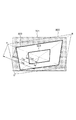
図3(A)に示すようにスクリーン面701に対して投射画像800がはみ出していた場合、本実施形態の状態判定部400は、投射画像800の頂点A、B、Dを検出できない。
As shown in FIG. 3A, when the
この場合、ステップS104へ進み、状態判定部400は、パターン生成部100に対して、頂点が検出できなかったことを通知する。該通知を受けたパターン生成部100は、テストパターンのサイズを縮小しステップS101へ戻る。
In this case, the process proceeds to step S104, and the
すなわち、パターン生成部100は、ステップS103における解析結果(所定の座標の検出結果)に応じて、ステップS104でテストパターンのサイズを変更する。本実施形態のパターン生成部100は、ステップS104において、縮小前のテストパターンを縦横均等に75%に縮小するが、縮小ステップは任意に決めることが出来る。また、縮小前と縮小後のテストパターンの中心は最大投射画面中心(投射部200が最大サイズで画像を投射した場合の投射画像の中心)と一致しているものとする。状態判定部400がステップS103で、4つの頂点を検出するまでステップS101からステップS104の処理が繰り返される。
That is, the
ステップS101からステップS104を繰り返した結果、例えば図3(B)に示すようにスクリーン面701上で投射画像802の頂点A、B、C、Dが検出されると、ステップS110に進む。本実施形態では、表示領域のサイズに対して縦横均等に75%に縮小されたテストパターンの投射画像802において、4つの頂点A、B、C、Dが検出されたものとする。
As a result of repeating Step S101 to Step S104, for example, when vertices A, B, C, and D of the projected
ステップS110において、状態判定部400は、縮小回数初期値RSが0と等しい否かを判定する。本実施形態では、RS=1として初期化されているため、RS≠0であると判定され、ステップS111に進む。ステップS111では、RS=RS−1となり、ステップS112へ進む。
In step S110, the
ステップS112では、パターン生成部100が、現在のサイズよりもさらに50%縮小したテストパターンを生成し、ステップS101へ戻る。本実施形態では、表示領域に対して縦横均等に75%に縮小されたサイズ変更後のテストパターンが、さらに縦横均等に50%に縮小されたテストパターンが生成される。
In step S112, the
なお、本実施形態ではRSの初期値を1としているが、2以上の値とすることも可能である。パターン生成部100は、4つの頂点が検出されたテストパターンよりもさらに縮小されたテストパターンを、縮小回数初期値RSに応じた数だけ生成する。
In this embodiment, the initial value of RS is set to 1, but it is possible to set the value to 2 or more. The
本実施形態ではRSの値を1としているので、4つの頂点が検出されたテストパターンよりもさらに50%縮小されたテストパターンが生成され、ステップS120へ進む。なお、例えば、RSの初期値を2にしていれば、4つの頂点が検出されたテストパターンがさらに50%縮小されたテストパターンが生成されると共に、当該50%縮小されたテストパターンがさらに50%縮小されたテストパターンが生成される。そして、撮像部300は、それぞれのテストパターンの撮像画像を状態判定部400へ送る。
In this embodiment, since the value of RS is 1, a test pattern further reduced by 50% is generated from the test pattern in which four vertices are detected, and the process proceeds to step S120. For example, if the initial value of RS is set to 2, a test pattern in which a test pattern in which four vertices are detected is further reduced by 50% is generated, and the test pattern reduced by 50% is further increased by 50. A test pattern reduced by% is generated. Then, the
ステップS120において、歪補正部500は、4つの頂点が検出された複数のテストパターンの撮像画像から最大投射サイズを特定する。すなわち、歪補正部500は、投射部200がテストパターンを縮小せずに投射した場合の投射画像800のサイズを特定する。
In step S120, the
本実施形態において、4つの頂点が検出された2つのテストパターンは、図4に示すように投射部200の表示領域サイズに対して縦横均等に75%(Rate2)に縮小された投射画像802と、それがさらに縦横均等に1/2された投射画像803である。つまり、投射画像803のサイズは、表示領域サイズが縦横均等に37.5%に縮小されたサイズである。本実施形態の歪補正部500は、投射画像802と投射画像803のそれぞれの頂点の位置に基づいて、投射画像800の各頂点の位置を算出する。すなわち、歪補正部500は、所定数(4つ)の頂点が検出されたテストパターンと、当該テストパターンの変更サイズ(Rate)とに基づいて、サイズの変更前の投射画像(投射画像800)の領域を特定する。
In the present embodiment, two test patterns in which four vertices are detected are a projected
例えば、図4において、投射画像800の左上の頂点Aを算出する方法について説明する。テストパターン中心から投射画像803、802、800の左上頂点までの距離をそれぞれLa3、La2、La0とする。
For example, referring to FIG. 4, a method for calculating the upper left vertex A of the
テストパターンの中心から投射画像803、802、800のそれぞれの左上頂点までの距離は線形比例している。例えば、テストパターンの中心から投射画像802の左上頂点までの距離L2は、投射画像802の50%のサイズである投射画像803の左上頂点までの距離L3の2倍である。
The distance from the center of the test pattern to the upper left vertex of each of the projected
つまり、テストパターンの縮小率(Rate)と、テストパターン中心から各投射画像の左上頂点までの距離(La)との関係は、αを定数として次式となる。
La=α*Rate
α=(La2−La3)/(Rate2−Rate3)
従って、テストパターン中心から投射画像800の左上頂点Aまでの距離La0はLa0=100*αとして算出される。歪補正部500は、投射画像800の他の頂点B、C、Dについても同様にテストパターン中心からの距離を算出し、これによって投射画像800のサイズを特定できる。
That is, the relationship between the test pattern reduction rate (Rate) and the distance (La) from the center of the test pattern to the upper left vertex of each projection image is represented by the following equation.
La = α * Rate
α = (La2-La3) / (Rate2-Rate3)
Accordingly, the distance La0 from the center of the test pattern to the upper left vertex A of the
歪補正部500は、テストパターンの中心から投射画像800の各頂点A、B、C、Dまでの距離から投射画像800の各頂点の位置を特定すると、ステップS130へ進む。ステップS130において、歪補正部500は、ステップS130で特定された投射画像800の各頂点の位置と歪み補正後の目標画像形状との関係から歪補正パラメータを算出する。
When the
より具体的には、図8(C)で示すように投射画像800が歪んで投射されている場合、歪補正部500は、以下のようにして歪補正パラメータを決定する。まず、歪補正部500は、スクリーン面701に投射されている投射画像800の4つの頂点座標A、B、C、Dを、図8(B)に示すように投射部200の表示領域上の座標Ap、Bp、Cp、Dpに変換するための座標変換式を求める。次に、歪補正部500は、スクリーン700上の座標A’、B’、C’、D’から投射部200の表示領域上の座標A’p、B’p、C’p、D’pを求める。そして、歪補正部500は、投射部200の表示領域上の座標Ap、Bp、Cp、Dpと座標A’p、B’p、C’p、D’pの差分から歪補正パラメータを算出する。このようにすることで、図8(C)の投射画像800のような歪んだ投射画像を補正して目標画像形状900のような形状にすることができる。
More specifically, when the
すなわち、歪補正部500は、スクリーン700上の座標と投射部200の表示領域上の座標との対応付けを行う。そして、歪補正部500は、該対応付けに従って、スクリーン700上の目標画像形状の頂点A’、B’、C’、D’の座標を投射部200の表示領域上の座標A’p、B’p、C’p、D’pに変換する。そして、歪補正部500は、表示領域上の座標Ap、Bp、Cp、Dpと座標A’p、B’p、C’p、D’pとの差分に基づいて歪み補正のための補正量を決定する。なお、歪補正パラメータの決定方法は上記の方法に限らず、公知の種々の方法を用いることが可能である。また、図8(A)は、最大投射サイズでの投射画像800がスクリーン700に収まった場合を示した図である。
That is, the
以上説明したように、本実施形態の画像処理装置は、投射画像から4つの頂点(所定の座標)が検出されなかった場合は、投射画像のサイズを縮小する。そして、画像処理装置は、縮小後の投射画像から頂点が検出されると、当該検出された頂点の位置を用いて、縮小前の投射画像の頂点の位置を特定し、歪み補正を行う。このようにすることで、例えば投射部200による投射画像サイズがスクリーン700よりも大きい場合であっても、より適切な歪み補正ができるようになる。
As described above, the image processing apparatus according to the present embodiment reduces the size of the projection image when four vertices (predetermined coordinates) are not detected from the projection image. Then, when a vertex is detected from the reduced projection image, the image processing apparatus specifies the position of the vertex of the projection image before reduction using the detected vertex position, and performs distortion correction. By doing so, for example, even when the projection image size by the
なお、本実施形態では、初めに4頂点を検出したテストパターンと更に1回縮小したテストパターンを使用する例を中心に説明したが、歪補正部500は、初めに4頂点を検出したテストパターンのみを使用して歪み補正を行うことも可能である。すなわち、歪補正部500は、最初に4頂点が検出されたテストパターンにおける4頂点と、当該テストパターンの縮小率から、縮小しなかった場合の投射画像800の頂点の位置を特定し、歪補正パラメータを決定することも可能である。
Note that, in the present embodiment, the description has focused on an example in which a test pattern in which four vertices are first detected and a test pattern that is further reduced once is used. However, the
また、3つ以上のテストパターンを使用して歪み補正をすることも可能である。3つ以上のテストパターンを使用する場合、使用するテストパターンの組合せ毎に上記の算出式のαを求め、それを平均することにより誤差を小さくすることができる。また、本実施形態では、テストパターンを白色のベタパターンとして説明したが、これに限るものではない。 It is also possible to correct distortion using three or more test patterns. When three or more test patterns are used, the error can be reduced by obtaining α in the above calculation formula for each combination of test patterns to be used, and averaging them. In the present embodiment, the test pattern is described as a white solid pattern, but the present invention is not limited to this.
また、本実施形態では、スクリーンに対する撮像画像から投射画像を解析する例を中心に説明しているが、この例に限らない。他の方法として、例えば、スクリーン上に設けられた輝度センサーで検出された輝度の情報を画像処理装置が取得して、それを解析することも可能である。 Further, in the present embodiment, an example in which a projection image is analyzed from a captured image on a screen has been mainly described, but the present invention is not limited to this example. As another method, for example, the image processing apparatus can acquire information on luminance detected by a luminance sensor provided on the screen and analyze it.
<第2の実施形態>
次に第2の実施形態について、第1の実施形態との差異を中心に説明する。本実施形態が第1の実施形態と大きく異なる点は、最初に縮小されたテストパターンを投射させ、4つの頂点が検出されると当該テストパターンを拡大している点である。なお、投射される画像はテストパターンに限らず、任意の画像データを用いることができる点は、第1の実施形態と同様である。
<Second Embodiment>
Next, the second embodiment will be described focusing on differences from the first embodiment. This embodiment differs greatly from the first embodiment in that a test pattern that is first reduced is projected, and when four vertices are detected, the test pattern is enlarged. The projected image is not limited to the test pattern, and any image data can be used as in the first embodiment.
本実施形態の画像処理装置の動作について、図5のフローチャートを用いて説明する。なお、図2のステップに対応するステップについては、同一のステップ番号としている。本実施形態の画像処理装置は、不図示のCPUを備えており、図5の処理を実行するために必要なプログラムを不図示のメモリから読み出して実行することにより、図5の各処理を実現する。 The operation of the image processing apparatus of this embodiment will be described with reference to the flowchart of FIG. Note that steps corresponding to the steps in FIG. 2 have the same step number. The image processing apparatus of the present embodiment includes a CPU (not shown), and implements each process of FIG. 5 by reading a program necessary for executing the process of FIG. 5 from a memory (not shown) and executing it. To do.
ステップS200で初期値として拡大回数値KS、縮小率SR、前縮小率ZDB、前拡大率ZUBを設定する。本実施形態例ではKS=10、SR=50%、ZDB=0%、ZUB=100%とする。各パラメータについては後述する。 In step S200, an enlargement number value KS, a reduction rate SR, a previous reduction rate ZDB, and a previous enlargement rate ZUB are set as initial values. In this embodiment, KS = 10, SR = 50%, ZDB = 0%, and ZUB = 100%. Each parameter will be described later.
ステップS101において、パターン生成部100は、初期縮小率SRで縮小されたテストパターンを生成する。そして、投射部200は、ステップS101において、テストパターンを投射する。本実施形態では初期縮小率SR=50%であるため、投射部200の表示領域サイズが縦横均等に50%に縮小されたテストパターンが投射される。
In step S101, the
ステップS102において、撮像部300は、テストパターンが投射された状態のスクリーン700を撮像する。そしてステップS103において、状態判定部400は、撮像部300による撮像画像からテストパターンの頂点を検出する。すなわち、状態判定部400は、投射部200による投射画像を解析する。ステップS103で撮像画像から検出される頂点数が4点ではなかった場合、ステップS105へ進む。ステップS105において、パターン生成部100は、テストパターンのサイズを縮小する。具体的には、パターン生成部100は、前縮小率ZDBと現縮小率SRの中間となる縮小率を設定する。図5の処理フローを開始してから最初でステップS105に進んだ場合、前縮小率ZDB=0%、現縮小率SR=50%であるためステップS105における変更後の縮小率SR=25%となる。また、ステップS105において、パターン生成部100は、前縮小率ZDBと現縮小率SRのうち大きい方を前拡大率(ZUB=50%)、小さい方を前縮小率(ZDB=0%)としてステップS101へ進む。
In step S102, the
なお、処理フローの途中でステップS105に進み、現縮小率SR=75%で前縮小率ZDB=50%であった場合、縮小率SR=62.5%、前縮小率ZDB=50%、前拡大率ZUB=75%となる。テストパターンの縮小とパラメータのアップデートが完了すると、S101へ進む。 If the current reduction rate SR = 75% and the previous reduction rate ZDB = 50%, the reduction rate SR = 62.5%, the previous reduction rate ZDB = 50%, and the previous reduction rate SR = 75%. The enlargement ratio ZUB = 75%. When the test pattern reduction and parameter update are completed, the process proceeds to S101.
ステップS103において、状態判定部400が撮像画像から4点の頂点を検出した場合、ステップS113へ進む。ステップS113において、状態判定部400は、拡大回数値KSが0であるか否かを判定する。KS≠0の場合、ステップS114でKS=KS−1としてステップS115へ進む。
In step S103, when the
ステップS115において、パターン生成部100は、前拡大率ZUBと現縮小率SRの中間となる縮小率になるようにテストパターンを拡大する。すなわち、本実施形態のパターン生成部100は、状態判定部400が投射画像の解析によって所定数(4つ)の頂点を検出した場合、投射部200による投射画像を拡大させる。図5の処理フローを開始してからステップS105を経由せずに最初にステップS115に進んだ場合、前拡大率ZUB=100%、現縮小率SR=50%なので縮小率SR=75%となる。
In step S115, the
また、前縮大率ZUBと現縮小率SRのうち大きい方を前拡大率(ZUB=100%)、小さい方を前縮小率(ZDB=50%)としてステップS101へ進む。また、例えば、ステップS115に進んだ場合において、現縮小率SR=75%で前拡大率ZUB=100%であった場合、拡大後の縮小率SR=87.5%、前縮小率ZDB=75%、前拡大率ZUB=100%としてステップS101へ進む。 Further, the larger one of the previous reduction ratio ZUB and the current reduction ratio SR is set as the previous enlargement ratio (ZUB = 100%), and the smaller one is set as the previous reduction ratio (ZDB = 50%), and the process proceeds to step S101. Further, for example, when the process proceeds to step S115, if the current reduction ratio SR = 75% and the previous enlargement ratio ZUB = 100%, the enlargement reduction ratio SR = 87.5% and the previous reduction ratio ZDB = 75. %, The previous enlargement ratio ZUB = 100%, and the process proceeds to step S101.
ステップS113で、拡大回数値KS=0となるまでステップS101からステップS113を繰り返してステップS120へ進む。すなわち、本実施形態のパターン生成部100は、第1のサイズのテストパターンの撮像画像から4つの頂点が検出された場合、テストパターンを所定の割合だけ拡大し、当該拡大後の第2のサイズのテストパターンを投射部200に投射させる。そして、パターン生成部100は、拡大後の第2のテストパターンの撮像画像から4つの頂点が検出されなかった場合、第1のテストパターンよりも大きく、第2のテストパターンよりも小さい第3のサイズのテストパターンを生成し、投射させる。
In step S113, steps S101 to S113 are repeated until the enlargement count value KS = 0, and the process proceeds to step S120. That is, when four vertices are detected from the captured image of the test pattern of the first size, the
ステップS113において拡大回数値KSが0になったと状態判定部400により判定されると、ステップS120に進む。ステップS120において、歪補正部500は、1つ又は複数のテストパターンの撮像画像のそれぞれから検出された4つの頂点の位置に基づいて投射部200の投射画像の補正量を決定する。
If the
以上説明したように、本実施形態の画像処理装置は、投射画像からの頂点の検出状況に応じて、テストパターンのサイズの縮小/拡大を行う。このようにすることで、投射画像(テストパターン)の全体がスクリーン面に投射されるサイズのうち、できるだけ大きなサイズのテストパターンの頂点の位置に基づいて歪み補正を行うことができる。 As described above, the image processing apparatus according to the present embodiment reduces / enlarges the size of the test pattern in accordance with the detection status of the vertices from the projection image. By doing in this way, distortion correction can be performed based on the position of the vertex of the test pattern having a size as large as possible out of the size in which the entire projected image (test pattern) is projected onto the screen surface.
<第3の実施形態>
次に第3の実施形態について、第1、及び第2の実施形態との差異を中心に説明する。本実施形態では、投射部200により投射されるテストパターンの内容に特徴がある。
<Third Embodiment>
Next, a third embodiment will be described focusing on differences from the first and second embodiments. In the present embodiment, the content of the test pattern projected by the
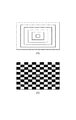
本実施形態で使用されるテストパターンの例を図6に示す。例えば、図6(A)は、中心が一致する複数の矩形で構成されるテストパターンである。図6(B)は、最大投射画像が縦横均一に縮小された矩形を並べたチェッカーパターンである。また、図6(B)でテストパターンの中心を明確にするため、中心の矩形は他の矩形と、例えば、色で識別可能なパターンとしている。すなわち、本実施形態で使用されるテストパターンは、複数の矩形が所定の位置関係で存在する画像である。このようなテストパターンは、中心が明確で、且つ、スクリーン上の画像サイズと、実際の投射画像のサイズとの差分や比率を推定可能なテストパターンである。なお、テストパターンはこれに限らない。 An example of the test pattern used in this embodiment is shown in FIG. For example, FIG. 6A shows a test pattern composed of a plurality of rectangles whose centers coincide. FIG. 6B shows a checker pattern in which rectangles obtained by reducing the maximum projected image uniformly in the vertical and horizontal directions are arranged. In addition, in order to clarify the center of the test pattern in FIG. 6B, the central rectangle is a pattern that can be distinguished from other rectangles, for example, by color. That is, the test pattern used in this embodiment is an image in which a plurality of rectangles exist in a predetermined positional relationship. Such a test pattern is a test pattern having a clear center and capable of estimating the difference or ratio between the image size on the screen and the size of the actual projected image. The test pattern is not limited to this.
本実施形態の画像処理装置の動作について、図7のフローチャートを用いて説明する。なお、図2のステップに対応するステップについては、同一のステップ番号としている。また、本実施形態の画像処理装置は、不図示のCPUを備えており、図7の処理を実行するために必要なプログラムを不図示のメモリから読み出して実行することにより、図7の各処理を実現する。 The operation of the image processing apparatus of this embodiment will be described with reference to the flowchart of FIG. Note that steps corresponding to the steps in FIG. 2 have the same step number. The image processing apparatus according to the present embodiment includes a CPU (not shown), and reads out and executes a program necessary for executing the process of FIG. Is realized.
ステップS101において、パターン生成部100は、図6(A)に示したようなテストパターンを生成する。そして、投射部200は、生成されたテストパターンを投射する。ステップS102において、撮像部300は、テストパターンが投射された状態のスクリーン700を撮像する。
In step S101, the
そしてステップS103において、状態判定部400は、図6(A)に示したテストパターンに含まれる複数の矩形のうち4つの頂点を検出可能な矩形を特定してステップS120へ進む。ステップS120において、歪補正部500は、4つの頂点が検出された矩形に基づいて、最大投射サイズの画像の各頂点を特定する。例えば、図6(A)のテストパターンが投射された場合、歪補正部500は、4つの頂点が検出された各矩形の頂点に基づいて、最も外側の矩形の頂点の位置を特定する。そして、歪補正部500は、ステップS130において、ステップS120で特定された最も外側の矩形の頂点の位置に基づいて、投射部200による投射画像の歪み補正のための補正量(補正パラメータ)を決定する。なお、図6(B)で示したテストパターンを用いた場合も、同様の考え方で補正パラメータを決定することが可能である。
In step S103, the
なお、図6(B)に示すようなテストパターンが投射された場合も、状態判定部400は、撮像画像から検出された範囲に基づいて、最大投射サイズの画像の各頂点を特定し、歪み補正のための制御を行なうことが可能である。
Note that even when a test pattern as shown in FIG. 6B is projected, the
以上説明したように、本実施形態の画像処理装置は、中心が明確、且つ、スクリーン上の画像サイズと、実際の投射画像のサイズとの差分や比率を推定可能なテストパターンを投射する。例えば、図6(A)のようなテストパターンを用いれば、スクリーン面に全体が投射されるテストパターンのうち、最も大きなテストパターンを短い時間で見つけることができる。そして、該テストパターンの頂点を用いて歪み補正パラメータを決定することで、テストパターンの投射画像がスクリーンからはみ出すようなことがある場合であっても、より適切な歪み補正ができるようになる。 As described above, the image processing apparatus according to the present embodiment projects a test pattern that has a clear center and can estimate the difference or ratio between the image size on the screen and the size of the actual projection image. For example, if a test pattern as shown in FIG. 6A is used, the largest test pattern can be found in a short time among the test patterns projected entirely on the screen surface. Then, by determining the distortion correction parameter using the vertex of the test pattern, even if the projected image of the test pattern sometimes protrudes from the screen, more appropriate distortion correction can be performed.
なお、上記の各実施形態では、投射画像が矩形であり、当該投射画像の4つの頂点を検出する例を中心に説明したが、この例に限らない。 In each of the above embodiments, the projection image has a rectangular shape, and the example in which the four vertices of the projection image are detected has been mainly described, but the present invention is not limited to this example.
Claims (16)
前記投射手段による投射画像を縮小する縮小処理を実行するかを、前記投射手段により画像が投射された投射面から取得される情報に基づいて判定する判定手段と、
前記判定手段により縮小処理を実行すると判定された場合、前記投射画像よりも縮小された第1縮小画像を前記投射手段に投射させる第1縮小処理と、前記第1縮小画像よりも縮小された第2縮小画像を前記投射手段に投射させる第2縮小処理とを少なくとも含む複数の縮小処理を実行する処理手段と、
前記処理手段により前記第1縮小画像が投射された投射面の撮像に基づく第1撮像画像から所定の座標が検出された場合、前記投射手段により投射される画像の歪み補正処理を前記第1及び第2の縮小画像に基づいて実行する補正手段を有することを特徴とする画像処理装置。 Projection means for projecting an image;
A determining means based on the information obtained from the projection surface on which the image is projected by the reduction or process is executed, the projection means to reduce the projected image that due to said projecting means,
If it is determined to perform the reduction by pre Symbol judging means, a first reduction processing to project the first reduced image reduced from the projected image on the projection unit, which is reduced than the first reduced image Processing means for executing a plurality of reduction processes including at least a second reduction process for projecting a second reduced image on the projection means ;
When a predetermined coordinate is detected from the first captured image based on the imaging of the projection surface on which the first reduced image is projected by the processing unit, the distortion correction processing of the image projected by the projection unit is performed in the first and An image processing apparatus, comprising: a correction unit that executes based on the second reduced image .
前記判定手段は、前記投射手段によりテストパターン画像が投射された投射面の撮像画像を用いることで、前記縮小処理を実行するかを判定することを特徴とする請求項1乃至7のうち、何れか1項に記載の画像処理装置。 The projection means projects a test pattern image having a predetermined pattern,
The determination means, by using the captured image of the projection surface of the test pattern image projected by the projection means, of the claims 1 to 7, wherein the determining whether to perform the reduction process, any The image processing apparatus according to claim 1.
前記投射手段による投射画像を縮小する縮小処理を実行するかを、前記投射手段により画像が投射された投射面から取得される情報に基づいて判定する判定工程と、
前記投射手段による投射画像を縮小する縮小処理を実行すると前記判定工程により判定された場合、前記投射画像よりも縮小された第1縮小画像を前記投射手段に投射させる第1縮小処理と、前記第1縮小画像よりも縮小された第2縮小画像を前記投射手段に投射させる第2縮小処理とを少なくとも含む複数の縮小処理を実行する処理工程と、
前記処理工程により前記第1縮小画像が投射された投射面の撮像に基づく第1撮像画像から所定の座標が検出された場合、前記投射手段により投射される画像の歪み補正処理を前記第1及び第2の縮小画像に基づいて実行する補正工程を有することを特徴とする制御方法。 A control method for controlling a projected image by projecting elevation means,
A determining step on the basis of the information obtained from the projection surface on which the image is projected by the reduction processing whether to perform a physical, said projecting means for reducing the projection image that due to said projecting means,
If it is determined by said determining step and performing a reduction process for reducing the projection image that due to said projecting means, a first reduction processing to project the first reduced image reduced from the projected image on the projection means, A processing step of executing a plurality of reduction processes including at least a second reduction process for projecting the second reduced image, which is reduced more than the first reduced image, to the projection unit ;
When a predetermined coordinate is detected from the first captured image based on the imaging of the projection surface on which the first reduced image is projected by the processing step, distortion correction processing of the image projected by the projection unit is performed in the first and A control method comprising a correction step executed based on the second reduced image .
前記投射手段による投射画像を拡大する拡大処理を実行する処理工程と、A processing step of executing an enlargement process for enlarging a projection image by the projection means;
前記処理工程による拡大処理の実行済み回数が所定回数に達した場合、前記投射手段による投射画像の歪み補正処理を実行すると判定する判定工程と、A determination step of determining that the projection image distortion correction processing by the projection means is executed when the number of times the enlargement processing by the processing step has been performed reaches a predetermined number of times;
前記判定工程により前記歪み補正処理を実行すると判定された場合、前記処理工程による複数回の拡大処理に基づく複数の投射画像に対応する複数の撮像画像のそれぞれから検出される所定の座標の位置情報に基づいて、前記投射手段による投射画像の歪み補正処理を実行する補正工程とを有することを特徴とする制御方法。Position information of predetermined coordinates detected from each of a plurality of captured images corresponding to a plurality of projection images based on a plurality of enlargement processes by the processing step when it is determined by the determination step that the distortion correction processing is executed. And a correction step of executing a distortion correction process of the projected image by the projection unit.
Priority Applications (3)
| Application Number | Priority Date | Filing Date | Title |
|---|---|---|---|
| JP2013251393A JP6274839B2 (en) | 2013-12-04 | 2013-12-04 | Image processing apparatus and image processing method |
| US14/559,743 US9551918B2 (en) | 2013-12-04 | 2014-12-03 | Image processing apparatus, image processing method, and computer-readable storage medium |
| US15/379,266 US9930306B2 (en) | 2013-12-04 | 2016-12-14 | Image processing apparatus, image processing method, and computer-readable storage medium |
Applications Claiming Priority (1)
| Application Number | Priority Date | Filing Date | Title |
|---|---|---|---|
| JP2013251393A JP6274839B2 (en) | 2013-12-04 | 2013-12-04 | Image processing apparatus and image processing method |
Publications (3)
| Publication Number | Publication Date |
|---|---|
| JP2015109559A JP2015109559A (en) | 2015-06-11 |
| JP2015109559A5 JP2015109559A5 (en) | 2017-06-01 |
| JP6274839B2 true JP6274839B2 (en) | 2018-02-07 |
Family
ID=53266400
Family Applications (1)
| Application Number | Title | Priority Date | Filing Date |
|---|---|---|---|
| JP2013251393A Expired - Fee Related JP6274839B2 (en) | 2013-12-04 | 2013-12-04 | Image processing apparatus and image processing method |
Country Status (2)
| Country | Link |
|---|---|
| US (2) | US9551918B2 (en) |
| JP (1) | JP6274839B2 (en) |
Families Citing this family (8)
| Publication number | Priority date | Publication date | Assignee | Title |
|---|---|---|---|---|
| FR3034889B1 (en) * | 2015-04-10 | 2017-04-28 | Cn2P Sas | ELECTRONIC BRACELET FOR DISPLAYING AN INTERACTIVE DIGITAL CONTENT TO BE PROJECTED ON A ZONE OF AN ARM |
| CN105072430B (en) * | 2015-08-19 | 2017-10-03 | 海信集团有限公司 | A kind of method and apparatus for adjusting projected image |
| JP6594170B2 (en) * | 2015-11-12 | 2019-10-23 | キヤノン株式会社 | Image processing apparatus, image processing method, image projection system, and program |
| US11393366B2 (en) * | 2017-07-11 | 2022-07-19 | Hewlett-Packard Development Company, L.P. | Projection calibrations |
| JP2019220887A (en) * | 2018-06-21 | 2019-12-26 | キヤノン株式会社 | Image processing system, image processing method, and program |
| JP7228966B2 (en) * | 2018-06-29 | 2023-02-27 | キヤノン株式会社 | Image processing device and its control method and program |
| CN115118941A (en) * | 2021-03-19 | 2022-09-27 | 三菱电机株式会社 | Projection device, projection method and memory |
| WO2023162688A1 (en) * | 2022-02-28 | 2023-08-31 | 富士フイルム株式会社 | Control device, control method, and control program |
Family Cites Families (13)
| Publication number | Priority date | Publication date | Assignee | Title |
|---|---|---|---|---|
| JP3996610B2 (en) | 2002-07-23 | 2007-10-24 | Necディスプレイソリューションズ株式会社 | Projector apparatus and image distortion correction method thereof |
| EP1385335B1 (en) * | 2002-07-23 | 2009-04-22 | NEC Display Solutions, Ltd. | Image projector with image-feedback control |
| JP4042695B2 (en) * | 2004-01-08 | 2008-02-06 | セイコーエプソン株式会社 | Projector and zoom adjustment method |
| JP5069038B2 (en) * | 2007-04-20 | 2012-11-07 | 三菱電機株式会社 | Rear projection display |
| JP5405047B2 (en) * | 2008-05-09 | 2014-02-05 | 三洋電機株式会社 | Projection display device |
| JP5266953B2 (en) * | 2008-08-19 | 2013-08-21 | セイコーエプソン株式会社 | Projection display apparatus and display method |
| CN102365866B (en) * | 2009-03-30 | 2014-05-21 | 日本电气株式会社 | Multiprojection display system and screen forming method |
| JP2011155412A (en) * | 2010-01-26 | 2011-08-11 | Panasonic Electric Works Co Ltd | Projection system and distortion correction method in the same |
| US8727539B2 (en) * | 2010-10-28 | 2014-05-20 | Seiko Epson Corporation | Projector and method of controlling projector |
| JP5644461B2 (en) * | 2010-12-14 | 2014-12-24 | 富士ゼロックス株式会社 | Image processing apparatus and program |
| JP2014056199A (en) * | 2012-09-14 | 2014-03-27 | Hitachi Media Electoronics Co Ltd | Scanning type projection device |
| JP6205777B2 (en) * | 2013-03-22 | 2017-10-04 | カシオ計算機株式会社 | Projection apparatus, projection method, and program for projection |
| JP6322993B2 (en) * | 2013-12-19 | 2018-05-16 | カシオ計算機株式会社 | Geometric correction adjustment method |
-
2013
- 2013-12-04 JP JP2013251393A patent/JP6274839B2/en not_active Expired - Fee Related
-
2014
- 2014-12-03 US US14/559,743 patent/US9551918B2/en active Active
-
2016
- 2016-12-14 US US15/379,266 patent/US9930306B2/en active Active
Also Published As
| Publication number | Publication date |
|---|---|
| US9930306B2 (en) | 2018-03-27 |
| US9551918B2 (en) | 2017-01-24 |
| JP2015109559A (en) | 2015-06-11 |
| US20170094237A1 (en) | 2017-03-30 |
| US20150156467A1 (en) | 2015-06-04 |
Similar Documents
| Publication | Publication Date | Title |
|---|---|---|
| JP6274839B2 (en) | Image processing apparatus and image processing method | |
| JP5521855B2 (en) | Projection image area detection device | |
| JP6525570B2 (en) | Image display system, control device, control method and program | |
| JP6115214B2 (en) | Pattern processing apparatus, pattern processing method, and pattern processing program | |
| US11025874B2 (en) | Image processing apparatus, control method, and non-transitory computer-readable storage medium | |
| JP2015173430A (en) | Projection system, semiconductor integrated circuit and image correction method | |
| JP2017188046A (en) | Image processing device and control method thereof, and image processing system | |
| JP2009159496A5 (en) | ||
| JP6566768B2 (en) | Information processing apparatus, information processing method, and program | |
| CN111083456A (en) | Projection correction method, projection correction device, projector and readable storage medium | |
| US20180220113A1 (en) | Projection display system, information processing apparatus, information processing method, and storage medium therefor | |
| US10992913B2 (en) | Image processing apparatus, method, and storage medium storing program for transforming distortion of image projected by projection apparatus | |
| US20170142384A1 (en) | Image processing apparatus, image processing method, image projection system, and storage medium | |
| US20180220114A1 (en) | System for controlling projector, information processing apparatus, information processing method, and storage medium | |
| JP2015109559A5 (en) | ||
| JP2011155412A (en) | Projection system and distortion correction method in the same | |
| JP5970012B2 (en) | Image processing apparatus and control method thereof | |
| JP2017212638A (en) | Display device, control method for display device, and program | |
| JP6543067B2 (en) | Projection system, projector device, imaging device, and program | |
| JP5955003B2 (en) | Image processing apparatus, image processing method, and program | |
| WO2018155269A1 (en) | Image processing device and method, and program | |
| JP2022088887A (en) | Adjustment method, measurement method, projection system, information processing apparatus, and program | |
| JP6307843B2 (en) | Interpolation method, program, and interpolation apparatus | |
| JP6074198B2 (en) | Image processing apparatus and image processing method | |
| JP2005012679A (en) | Projector with inclination measurement instrument |
Legal Events
| Date | Code | Title | Description |
|---|---|---|---|
| A621 | Written request for application examination |
Free format text: JAPANESE INTERMEDIATE CODE: A621 Effective date: 20161202 |
|
| A521 | Request for written amendment filed |
Free format text: JAPANESE INTERMEDIATE CODE: A523 Effective date: 20170414 |
|
| A977 | Report on retrieval |
Free format text: JAPANESE INTERMEDIATE CODE: A971007 Effective date: 20170720 |
|
| A131 | Notification of reasons for refusal |
Free format text: JAPANESE INTERMEDIATE CODE: A131 Effective date: 20170808 |
|
| A521 | Request for written amendment filed |
Free format text: JAPANESE INTERMEDIATE CODE: A523 Effective date: 20171005 |
|
| TRDD | Decision of grant or rejection written | ||
| A01 | Written decision to grant a patent or to grant a registration (utility model) |
Free format text: JAPANESE INTERMEDIATE CODE: A01 Effective date: 20171212 |
|
| A61 | First payment of annual fees (during grant procedure) |
Free format text: JAPANESE INTERMEDIATE CODE: A61 Effective date: 20180109 |
|
| R151 | Written notification of patent or utility model registration |
Ref document number: 6274839 Country of ref document: JP Free format text: JAPANESE INTERMEDIATE CODE: R151 |
|
| LAPS | Cancellation because of no payment of annual fees |