JP6273595B1 - Phosphor and light emitting device - Google Patents
Phosphor and light emitting device Download PDFInfo
- Publication number
- JP6273595B1 JP6273595B1 JP2017548074A JP2017548074A JP6273595B1 JP 6273595 B1 JP6273595 B1 JP 6273595B1 JP 2017548074 A JP2017548074 A JP 2017548074A JP 2017548074 A JP2017548074 A JP 2017548074A JP 6273595 B1 JP6273595 B1 JP 6273595B1
- Authority
- JP
- Japan
- Prior art keywords
- phosphor
- compound
- alo
- light
- end component
- Prior art date
- Legal status (The legal status is an assumption and is not a legal conclusion. Google has not performed a legal analysis and makes no representation as to the accuracy of the status listed.)
- Active
Links
- OAICVXFJPJFONN-UHFFFAOYSA-N Phosphorus Chemical compound [P] OAICVXFJPJFONN-UHFFFAOYSA-N 0.000 title claims abstract description 257
- 150000001875 compounds Chemical class 0.000 claims abstract description 208
- 239000002223 garnet Substances 0.000 claims abstract description 108
- 239000006104 solid solution Substances 0.000 claims abstract description 79
- 239000011159 matrix material Substances 0.000 claims abstract description 9
- 239000007787 solid Substances 0.000 claims abstract description 9
- 229910004283 SiO 4 Inorganic materials 0.000 claims description 53
- 229910052909 inorganic silicate Inorganic materials 0.000 abstract 1
- 230000005284 excitation Effects 0.000 description 48
- 239000011777 magnesium Substances 0.000 description 44
- 238000010791 quenching Methods 0.000 description 39
- 230000000171 quenching effect Effects 0.000 description 39
- 239000002994 raw material Substances 0.000 description 34
- 230000000052 comparative effect Effects 0.000 description 33
- 238000002441 X-ray diffraction Methods 0.000 description 32
- 239000011575 calcium Substances 0.000 description 31
- 238000000295 emission spectrum Methods 0.000 description 31
- 238000006243 chemical reaction Methods 0.000 description 21
- 239000000758 substrate Substances 0.000 description 20
- 238000000695 excitation spectrum Methods 0.000 description 18
- 229910019018 Mg 2 Si Inorganic materials 0.000 description 17
- 239000000203 mixture Substances 0.000 description 17
- 239000007789 gas Substances 0.000 description 16
- 239000000126 substance Substances 0.000 description 13
- 238000002156 mixing Methods 0.000 description 12
- 238000004458 analytical method Methods 0.000 description 10
- 239000013078 crystal Substances 0.000 description 8
- 238000005286 illumination Methods 0.000 description 8
- 238000012423 maintenance Methods 0.000 description 8
- 238000012360 testing method Methods 0.000 description 8
- 229910052782 aluminium Inorganic materials 0.000 description 7
- 238000010304 firing Methods 0.000 description 7
- 230000015572 biosynthetic process Effects 0.000 description 6
- 238000005259 measurement Methods 0.000 description 6
- 230000003287 optical effect Effects 0.000 description 6
- 230000007704 transition Effects 0.000 description 6
- PNEYBMLMFCGWSK-UHFFFAOYSA-N aluminium oxide Inorganic materials [O-2].[O-2].[O-2].[Al+3].[Al+3] PNEYBMLMFCGWSK-UHFFFAOYSA-N 0.000 description 5
- 239000004570 mortar (masonry) Substances 0.000 description 5
- 230000009467 reduction Effects 0.000 description 5
- 238000003786 synthesis reaction Methods 0.000 description 5
- 230000007423 decrease Effects 0.000 description 4
- 238000011156 evaluation Methods 0.000 description 4
- 238000002284 excitation--emission spectrum Methods 0.000 description 4
- 239000011521 glass Substances 0.000 description 4
- 229910052749 magnesium Inorganic materials 0.000 description 4
- 239000000463 material Substances 0.000 description 4
- 229910052688 Gadolinium Inorganic materials 0.000 description 3
- VYPSYNLAJGMNEJ-UHFFFAOYSA-N Silicium dioxide Chemical compound O=[Si]=O VYPSYNLAJGMNEJ-UHFFFAOYSA-N 0.000 description 3
- 239000000919 ceramic Substances 0.000 description 3
- 238000010586 diagram Methods 0.000 description 3
- 238000001035 drying Methods 0.000 description 3
- 230000000694 effects Effects 0.000 description 3
- 238000010894 electron beam technology Methods 0.000 description 3
- 239000001257 hydrogen Substances 0.000 description 3
- 229910052739 hydrogen Inorganic materials 0.000 description 3
- 239000002245 particle Substances 0.000 description 3
- 239000000843 powder Substances 0.000 description 3
- -1 rare earth ions Chemical class 0.000 description 3
- 229910052761 rare earth metal Inorganic materials 0.000 description 3
- 238000009877 rendering Methods 0.000 description 3
- 239000004065 semiconductor Substances 0.000 description 3
- 229910052710 silicon Inorganic materials 0.000 description 3
- 229910001428 transition metal ion Inorganic materials 0.000 description 3
- XLYOFNOQVPJJNP-UHFFFAOYSA-N water Substances O XLYOFNOQVPJJNP-UHFFFAOYSA-N 0.000 description 3
- 238000005303 weighing Methods 0.000 description 3
- 229910052727 yttrium Inorganic materials 0.000 description 3
- VTYYLEPIZMXCLO-UHFFFAOYSA-L Calcium carbonate Chemical compound [Ca+2].[O-]C([O-])=O VTYYLEPIZMXCLO-UHFFFAOYSA-L 0.000 description 2
- 229910004298 SiO 2 Inorganic materials 0.000 description 2
- JNDMLEXHDPKVFC-UHFFFAOYSA-N aluminum;oxygen(2-);yttrium(3+) Chemical compound [O-2].[O-2].[O-2].[Al+3].[Y+3] JNDMLEXHDPKVFC-UHFFFAOYSA-N 0.000 description 2
- 230000005283 ground state Effects 0.000 description 2
- 239000000395 magnesium oxide Substances 0.000 description 2
- CPLXHLVBOLITMK-UHFFFAOYSA-N magnesium oxide Inorganic materials [Mg]=O CPLXHLVBOLITMK-UHFFFAOYSA-N 0.000 description 2
- AXZKOIWUVFPNLO-UHFFFAOYSA-N magnesium;oxygen(2-) Chemical compound [O-2].[Mg+2] AXZKOIWUVFPNLO-UHFFFAOYSA-N 0.000 description 2
- 238000012986 modification Methods 0.000 description 2
- 230000004048 modification Effects 0.000 description 2
- 238000005375 photometry Methods 0.000 description 2
- 230000003595 spectral effect Effects 0.000 description 2
- 238000012795 verification Methods 0.000 description 2
- 229910019901 yttrium aluminum garnet Inorganic materials 0.000 description 2
- 229910002012 Aerosil® Inorganic materials 0.000 description 1
- 229910002016 Aerosil® 200 Inorganic materials 0.000 description 1
- 229910018072 Al 2 O 3 Inorganic materials 0.000 description 1
- KLZUFWVZNOTSEM-UHFFFAOYSA-K Aluminium flouride Chemical compound F[Al](F)F KLZUFWVZNOTSEM-UHFFFAOYSA-K 0.000 description 1
- 229910052765 Lutetium Inorganic materials 0.000 description 1
- 230000009471 action Effects 0.000 description 1
- 239000011230 binding agent Substances 0.000 description 1
- 229910052791 calcium Inorganic materials 0.000 description 1
- 229910000019 calcium carbonate Inorganic materials 0.000 description 1
- 229910000420 cerium oxide Inorganic materials 0.000 description 1
- 239000003086 colorant Substances 0.000 description 1
- 238000005401 electroluminescence Methods 0.000 description 1
- 230000005281 excited state Effects 0.000 description 1
- CMIHHWBVHJVIGI-UHFFFAOYSA-N gadolinium(iii) oxide Chemical compound [O-2].[O-2].[O-2].[Gd+3].[Gd+3] CMIHHWBVHJVIGI-UHFFFAOYSA-N 0.000 description 1
- 238000010438 heat treatment Methods 0.000 description 1
- 239000004973 liquid crystal related substance Substances 0.000 description 1
- 229910003443 lutetium oxide Inorganic materials 0.000 description 1
- 230000014759 maintenance of location Effects 0.000 description 1
- 230000008774 maternal effect Effects 0.000 description 1
- 230000007246 mechanism Effects 0.000 description 1
- QSHDDOUJBYECFT-UHFFFAOYSA-N mercury Chemical compound [Hg] QSHDDOUJBYECFT-UHFFFAOYSA-N 0.000 description 1
- 229910052753 mercury Inorganic materials 0.000 description 1
- 229910052751 metal Inorganic materials 0.000 description 1
- 239000002184 metal Substances 0.000 description 1
- TWNQGVIAIRXVLR-UHFFFAOYSA-N oxo(oxoalumanyloxy)alumane Chemical compound O=[Al]O[Al]=O TWNQGVIAIRXVLR-UHFFFAOYSA-N 0.000 description 1
- BMMGVYCKOGBVEV-UHFFFAOYSA-N oxo(oxoceriooxy)cerium Chemical compound [Ce]=O.O=[Ce]=O BMMGVYCKOGBVEV-UHFFFAOYSA-N 0.000 description 1
- MPARYNQUYZOBJM-UHFFFAOYSA-N oxo(oxolutetiooxy)lutetium Chemical compound O=[Lu]O[Lu]=O MPARYNQUYZOBJM-UHFFFAOYSA-N 0.000 description 1
- SIWVEOZUMHYXCS-UHFFFAOYSA-N oxo(oxoyttriooxy)yttrium Chemical compound O=[Y]O[Y]=O SIWVEOZUMHYXCS-UHFFFAOYSA-N 0.000 description 1
- BWHMMNNQKKPAPP-UHFFFAOYSA-L potassium carbonate Chemical compound [K+].[K+].[O-]C([O-])=O BWHMMNNQKKPAPP-UHFFFAOYSA-L 0.000 description 1
- 230000005855 radiation Effects 0.000 description 1
- 239000011347 resin Substances 0.000 description 1
- 229920005989 resin Polymers 0.000 description 1
- 239000000377 silicon dioxide Substances 0.000 description 1
- 235000012239 silicon dioxide Nutrition 0.000 description 1
- 238000003746 solid phase reaction Methods 0.000 description 1
- 238000001228 spectrum Methods 0.000 description 1
- 238000001308 synthesis method Methods 0.000 description 1
Images


Classifications
-
- C—CHEMISTRY; METALLURGY
- C09—DYES; PAINTS; POLISHES; NATURAL RESINS; ADHESIVES; COMPOSITIONS NOT OTHERWISE PROVIDED FOR; APPLICATIONS OF MATERIALS NOT OTHERWISE PROVIDED FOR
- C09K—MATERIALS FOR MISCELLANEOUS APPLICATIONS, NOT PROVIDED FOR ELSEWHERE
- C09K11/00—Luminescent, e.g. electroluminescent, chemiluminescent materials
- C09K11/08—Luminescent, e.g. electroluminescent, chemiluminescent materials containing inorganic luminescent materials
- C09K11/77—Luminescent, e.g. electroluminescent, chemiluminescent materials containing inorganic luminescent materials containing rare earth metals
- C09K11/7766—Luminescent, e.g. electroluminescent, chemiluminescent materials containing inorganic luminescent materials containing rare earth metals containing two or more rare earth metals
- C09K11/77742—Silicates
-
- H—ELECTRICITY
- H01—ELECTRIC ELEMENTS
- H01L—SEMICONDUCTOR DEVICES NOT COVERED BY CLASS H10
- H01L33/00—Semiconductor devices having potential barriers specially adapted for light emission; Processes or apparatus specially adapted for the manufacture or treatment thereof or of parts thereof; Details thereof
- H01L33/48—Semiconductor devices having potential barriers specially adapted for light emission; Processes or apparatus specially adapted for the manufacture or treatment thereof or of parts thereof; Details thereof characterised by the semiconductor body packages
- H01L33/50—Wavelength conversion elements
- H01L33/501—Wavelength conversion elements characterised by the materials, e.g. binder
- H01L33/502—Wavelength conversion materials
- H01L33/504—Elements with two or more wavelength conversion materials
-
- C—CHEMISTRY; METALLURGY
- C09—DYES; PAINTS; POLISHES; NATURAL RESINS; ADHESIVES; COMPOSITIONS NOT OTHERWISE PROVIDED FOR; APPLICATIONS OF MATERIALS NOT OTHERWISE PROVIDED FOR
- C09K—MATERIALS FOR MISCELLANEOUS APPLICATIONS, NOT PROVIDED FOR ELSEWHERE
- C09K11/00—Luminescent, e.g. electroluminescent, chemiluminescent materials
- C09K11/08—Luminescent, e.g. electroluminescent, chemiluminescent materials containing inorganic luminescent materials
- C09K11/77—Luminescent, e.g. electroluminescent, chemiluminescent materials containing inorganic luminescent materials containing rare earth metals
- C09K11/7766—Luminescent, e.g. electroluminescent, chemiluminescent materials containing inorganic luminescent materials containing rare earth metals containing two or more rare earth metals
- C09K11/7774—Aluminates
-
- H—ELECTRICITY
- H01—ELECTRIC ELEMENTS
- H01L—SEMICONDUCTOR DEVICES NOT COVERED BY CLASS H10
- H01L33/00—Semiconductor devices having potential barriers specially adapted for light emission; Processes or apparatus specially adapted for the manufacture or treatment thereof or of parts thereof; Details thereof
- H01L33/48—Semiconductor devices having potential barriers specially adapted for light emission; Processes or apparatus specially adapted for the manufacture or treatment thereof or of parts thereof; Details thereof characterised by the semiconductor body packages
- H01L33/50—Wavelength conversion elements
- H01L33/505—Wavelength conversion elements characterised by the shape, e.g. plate or foil
-
- H—ELECTRICITY
- H01—ELECTRIC ELEMENTS
- H01S—DEVICES USING THE PROCESS OF LIGHT AMPLIFICATION BY STIMULATED EMISSION OF RADIATION [LASER] TO AMPLIFY OR GENERATE LIGHT; DEVICES USING STIMULATED EMISSION OF ELECTROMAGNETIC RADIATION IN WAVE RANGES OTHER THAN OPTICAL
- H01S5/00—Semiconductor lasers
- H01S5/02—Structural details or components not essential to laser action
-
- H—ELECTRICITY
- H01—ELECTRIC ELEMENTS
- H01L—SEMICONDUCTOR DEVICES NOT COVERED BY CLASS H10
- H01L2933/00—Details relating to devices covered by the group H01L33/00 but not provided for in its subgroups
- H01L2933/0008—Processes
- H01L2933/0033—Processes relating to semiconductor body packages
- H01L2933/0041—Processes relating to semiconductor body packages relating to wavelength conversion elements
Landscapes
- Engineering & Computer Science (AREA)
- Chemical & Material Sciences (AREA)
- Microelectronics & Electronic Packaging (AREA)
- Manufacturing & Machinery (AREA)
- Computer Hardware Design (AREA)
- Power Engineering (AREA)
- Physics & Mathematics (AREA)
- Inorganic Chemistry (AREA)
- Materials Engineering (AREA)
- Organic Chemistry (AREA)
- Condensed Matter Physics & Semiconductors (AREA)
- General Physics & Mathematics (AREA)
- Electromagnetism (AREA)
- Optics & Photonics (AREA)
- Luminescent Compositions (AREA)
- Optical Filters (AREA)
- Led Device Packages (AREA)
- Projection Apparatus (AREA)
- Silicates, Zeolites, And Molecular Sieves (AREA)
- Semiconductor Lasers (AREA)
- Non-Portable Lighting Devices Or Systems Thereof (AREA)
Abstract
本発明の蛍光体は、ガーネット構造を有する母体ガーネット化合物中に、発光中心であるCe3+が含まれてなる蛍光体であり、前記母体ガーネット化合物は2種以上の端成分からなる固溶体であり、前記端成分は第1の端成分としてLu2CaMg2(SiO4)3を含む。前記母体ガーネット化合物は、Alを含む化合物であることが好ましい。本発明の発光装置は、本発明の蛍光体2を用い、固体発光素子117を備え、蛍光体2は、固体発光素子117が放射する光により励起される。The phosphor of the present invention is a phosphor in which Ce3 + that is an emission center is contained in a matrix garnet compound having a garnet structure, and the matrix garnet compound is a solid solution composed of two or more end components, The end component includes Lu2CaMg2 (SiO4) 3 as the first end component. The parent garnet compound is preferably a compound containing Al. The light-emitting device of the present invention uses the phosphor 2 of the present invention and includes a solid light-emitting element 117, and the phosphor 2 is excited by light emitted from the solid light-emitting element 117.
Description
本発明は、例えば、半導体レーザーダイオード(LD)等の固体発光素子と共に用いられ、プロジェクター等の表示装置や照明装置の光源に使用される蛍光体として幅広く利用できる、新規なガーネット蛍光体、及び、この蛍光体を用いた発光装置に関する。 The present invention is, for example, a novel garnet phosphor that is used together with a solid-state light emitting element such as a semiconductor laser diode (LD) and can be widely used as a phosphor used in a light source of a display device such as a projector or a lighting device, and The present invention relates to a light emitting device using this phosphor.
従来、「ガーネット構造」と呼ばれる結晶構造を有する化合物が知られている。このガーネット構造を有する化合物の一つとして、Y3Al2(AlO4)3で表される化合物が知られている。このY3Al2(AlO4)3は、イットリウムアルミニウムガーネット(YAG)という略称で広く知られている。このY3Al2(AlO4)3は、固体レーザー、透光性セラミックス、蛍光体等に利用されている。Conventionally, compounds having a crystal structure called “garnet structure” are known. As one of compounds having this garnet structure, a compound represented by Y 3 Al 2 (AlO 4 ) 3 is known. Y 3 Al 2 (AlO 4 ) 3 is widely known as an abbreviation called yttrium aluminum garnet (YAG). This Y 3 Al 2 (AlO 4 ) 3 is used for solid lasers, translucent ceramics, phosphors and the like.
ここで、蛍光体とは、紫外線励起等の刺激を与えることによって、蛍光を放射する化合物である。蛍光体では、蛍光体を構成する特定の原子の核外電子が紫外線等によって励起された後、基底状態に戻るときに、励起状態と基底状態とのエネルギーレベルの差が可視光として放出される。蛍光体は、例えば、ガーネット構造を有するY3Al2(AlO4)3等の化合物に、発光中心としての希土類イオンや遷移金属イオン(Ce3+、Tb3+、Eu3+、Mn2+、Mn4+、Fe3+、Cr3+等)を含ませることにより得られる。Here, the phosphor is a compound that emits fluorescence by giving a stimulus such as ultraviolet excitation. In a phosphor, when the extranuclear electrons of specific atoms constituting the phosphor are excited by ultraviolet rays or the like and then return to the ground state, the difference in energy level between the excited state and the ground state is emitted as visible light. . For example, phosphors include compounds such as Y 3 Al 2 (AlO 4 ) 3 having a garnet structure, rare earth ions or transition metal ions (Ce 3+ , Tb 3+ , Eu 3+ , Mn 2+ , Mn 4+ , (Fe 3+ , Cr 3+ etc.).
以下、本明細書では、ガーネット構造を有する化合物に、発光中心としての希土類イオンや遷移金属イオン(Ce3+、Tb3+、Eu3+、Mn2+、Mn4+、Fe3+、Cr3+等)を含ませてなる蛍光体を、ガーネット蛍光体ともいう。なお、本明細書では、ガーネット蛍光体を単に蛍光体ということがある。Hereinafter, in the present specification, a compound having a garnet structure includes rare earth ions or transition metal ions (Ce 3+ , Tb 3+ , Eu 3+ , Mn 2+ , Mn 4+ , Fe 3+ , Cr 3+, etc.) as luminescent centers. This phosphor is also called a garnet phosphor. In the present specification, the garnet phosphor may be simply referred to as a phosphor.
また、ガーネット構造を有するY3Al2(AlO4)3に、発光中心としての希土類イオンや遷移金属イオン(Ce3+、Tb3+、Eu3+、Mn2+、Mn4+、Fe3+、Cr3+等)を含ませてなる蛍光体を、Y3Al2(AlO4)3蛍光体ともいう。Moreover, rare earth ions or transition metal ions (Ce 3+ , Tb 3+ , Eu 3+ , Mn 2+ , Mn 4+ , Fe 3+ , Cr 3+, etc.) as the emission center are added to Y 3 Al 2 (AlO 4 ) 3 having a garnet structure. The phosphor containing this is also referred to as a Y 3 Al 2 (AlO 4 ) 3 phosphor.
さらに、便宜上、発光中心としてCe3+を少なくとも含むY3Al2(AlO4)3蛍光体を、Y3Al2(AlO4)3:Ce3+蛍光体ともいう。Furthermore, for the sake of convenience, a Y 3 Al 2 (AlO 4 ) 3 phosphor containing at least Ce 3+ as an emission center is also referred to as a Y 3 Al 2 (AlO 4 ) 3 : Ce 3+ phosphor.
Y3Al2(AlO4)3:Ce3+蛍光体は、電子線、真空紫外線、そして青色光等の、粒子線又は電磁波を照射すると、励起されて、黄緑色の可視光を放射することが知られている。また、Y3Al2(AlO4)3:Ce3+蛍光体は、1/10残光が100ns以下と極めて短いことも知られている。このため、Y3Al2(AlO4)3:Ce3+蛍光体は数多くの発光装置に幅広く利用されている。Y 3 Al 2 (AlO 4 ) 3 : Ce 3+ phosphor may be excited to emit yellowish green visible light when irradiated with particle beam or electromagnetic wave such as electron beam, vacuum ultraviolet ray, and blue light. Are known. It is also known that Y 3 Al 2 (AlO 4 ) 3 : Ce 3+ phosphor has an extremely short 1/10 afterglow of 100 ns or less. For this reason, Y 3 Al 2 (AlO 4 ) 3 : Ce 3+ phosphor is widely used in many light emitting devices.
上記のように、Y3Al2(AlO4)3:Ce3+蛍光体が放射する光の光色は黄緑色である。これに対して、Y3Al2(AlO4)3:Ce3+蛍光体を構成する元素の一部又は全部を、イオン半径等が異なる他の元素で置換すると、Y3Al2(AlO4)3:Ce3+蛍光体と異なる光色を放射する蛍光体になることが知られている。As described above, the light color of the light emitted from the Y 3 Al 2 (AlO 4 ) 3 : Ce 3+ phosphor is yellowish green. On the other hand, when a part or all of the elements constituting the Y 3 Al 2 (AlO 4 ) 3 : Ce 3+ phosphor are replaced with other elements having different ionic radii or the like, Y 3 Al 2 (AlO 4 ) 3 : It is known that the phosphor emits a light color different from that of the Ce 3+ phosphor.
例えば、Y3Al2(AlO4)3:Ce3+蛍光体よりも、短波長の光色を放射するガーネット蛍光体として、Y3Al2(AlO4)3:Ce3+蛍光体を構成するYをLuで置換したLu3Al2(AlO4)3:Ce3+蛍光体が知られている。Lu3Al2(AlO4)3:Ce3+蛍光体は、緑色の可視光を放射する。すなわち、Lu3Al2(AlO4)3:Ce3+蛍光体の発光ピーク波長は、Y3Al2(AlO4)3:Ce3+蛍光体の発光ピーク波長よりも相対的に短い。For example, Y 3 Al 2 (AlO 4 ) 3 : Ce 3+ phosphor is formed as a garnet phosphor that emits a light color with a shorter wavelength than Y 3 Al 2 (AlO 4 ) 3 : Ce 3+ phosphor. Lu 3 Al 2 (AlO 4 ) 3 : Ce 3+ phosphor in which is substituted with Lu is known. The Lu 3 Al 2 (AlO 4 ) 3 : Ce 3+ phosphor emits green visible light. That is, the emission peak wavelength of Lu 3 Al 2 (AlO 4 ) 3 : Ce 3+ phosphor is relatively shorter than the emission peak wavelength of Y 3 Al 2 (AlO 4 ) 3 : Ce 3+ phosphor.
一方、Y3Al2(AlO4)3:Ce3+蛍光体よりも、長波長の光色を放射するガーネット蛍光体が知られている(例えば、特許文献1参照)。このガーネット蛍光体は、Y3Al2(AlO4)3:Ce3+蛍光体を構成するYの一部をGdで置換した(Y,Gd)3Al2(AlO4)3:Ce3+蛍光体である。(Y,Gd)3Al2(AlO4)3:Ce3+蛍光体は、黄緑色から橙色の可視光を放射する。On the other hand, a garnet phosphor that emits light having a longer wavelength than Y 3 Al 2 (AlO 4 ) 3 : Ce 3+ phosphor is known (see, for example, Patent Document 1). In this garnet phosphor, Y 3 Al 2 (AlO 4 ) 3 : Ce 3+ a part of Y constituting the phosphor is substituted with Gd (Y, Gd) 3 Al 2 (AlO 4 ) 3 : Ce 3+ phosphor It is. The (Y, Gd) 3 Al 2 (AlO 4 ) 3 : Ce 3+ phosphor emits yellow-orange to orange visible light.
また、Y3Al2(AlO4)3:Ce3+蛍光体よりも、長波長の光色を放射する他のガーネット蛍光体も知られている(例えば、特許文献2参照)。このガーネット蛍光体は、Y3Al2(AlO4)3:Ce3+蛍光体を構成するAlの一部又は全部をMgで置換し、かつ、(AlO4)基の一部又は全部を(SiO4)基で置換したY3(Al,Mg)2((Al,Si)O4)3:Ce3+蛍光体である。Y3(Al,Mg)2((Al,Si)O4)3:Ce3+蛍光体は、黄緑色から赤色の可視光を放射する。In addition, other garnet phosphors that emit light having a longer wavelength than Y 3 Al 2 (AlO 4 ) 3 : Ce 3+ phosphors are also known (see, for example, Patent Document 2). In this garnet phosphor, a part or all of Al constituting the Y 3 Al 2 (AlO 4 ) 3 : Ce 3+ phosphor is substituted with Mg, and a part or all of the (AlO 4 ) group is replaced with (
さらに、Y3Al2(AlO4)3:Ce3+蛍光体よりも、長波長の光色を放射するさらに他のガーネット蛍光体も知られている(例えば、特許文献3参照)。このガーネット蛍光体は、Y3Al2(AlO4)3:Ce3+蛍光体を構成するYをLu及びCaで置換し、AlをMgで置換し、かつ(AlO4)基を(SiO4)基で置換したLu2CaMg2(SiO4)3:Ce3+蛍光体である。Lu2CaMg2(SiO4)3:Ce3+蛍光体は、橙色の可視光を放射する。Furthermore, other garnet phosphors that emit light colors with longer wavelengths than Y 3 Al 2 (AlO 4 ) 3 : Ce 3+ phosphors are also known (see, for example, Patent Document 3). In this garnet phosphor, Y constituting the Y 3 Al 2 (AlO 4 ) 3 : Ce 3+ phosphor is substituted with Lu and Ca, Al is substituted with Mg, and an (AlO 4 ) group is (SiO 4 ). This is a Lu 2 CaMg 2 (SiO 4 ) 3 : Ce 3+ phosphor substituted with a group. The Lu 2 CaMg 2 (SiO 4 ) 3 : Ce 3+ phosphor emits orange visible light.
これらのY3Al2(AlO4)3:Ce3+蛍光体よりも発光ピーク波長が相対的に長いガーネット蛍光体は、Y3Al2(AlO4)3:Ce3+蛍光体よりも色調の面で優れるため、発光装置等への応用が検討されている。These Y 3 Al 2 (AlO 4 ) 3 : Ce 3+ phosphors have a longer emission peak wavelength than the Y 3 Al 2 (AlO 4 ) 3 : Ce 3+ phosphor. Therefore, application to light emitting devices and the like is being studied.
しかしながら、Y3Al2(AlO4)3:Ce3+蛍光体よりも発光ピーク波長が相対的に長いガーネット蛍光体は、温度消光が大きいという課題があった。ここで、温度消光とは、蛍光体温度の上昇とともに発光効率が低下する現象である。However, a garnet phosphor having a longer emission peak wavelength than the Y 3 Al 2 (AlO 4 ) 3 : Ce 3+ phosphor has a problem that temperature quenching is large. Here, temperature quenching is a phenomenon in which the luminous efficiency decreases as the phosphor temperature increases.
本発明は、上記課題を解決するためになされたものであり、発光ピーク波長が相対的に長く、温度消光が改善された、新規なガーネット蛍光体及びこれを用いた発光装置を提供することを目的とする。 The present invention has been made to solve the above problems, and provides a novel garnet phosphor having a relatively long emission peak wavelength and improved temperature quenching, and a light emitting device using the same. Objective.
上記課題を解決するために、本発明の第一の態様に係る蛍光体は、ガーネット構造を有する母体ガーネット化合物中に、発光中心であるCe3+が含まれてなる蛍光体であり、前記母体ガーネット化合物は2種以上の端成分からなる固溶体である。前記端成分は第1の端成分としてLu2CaMg2(SiO4)3を含む。In order to solve the above-mentioned problem, the phosphor according to the first aspect of the present invention is a phosphor in which Ce 3+ which is an emission center is contained in a host garnet compound having a garnet structure, and the host garnet The compound is a solid solution composed of two or more end components. The end component includes Lu 2 CaMg 2 (SiO 4 ) 3 as a first end component.
また、本発明の第二の態様に係る発光装置は、上記蛍光体を用いる。 Moreover, the light emitting device according to the second aspect of the present invention uses the phosphor.
以下、実施形態に係る蛍光体及び当該蛍光体を用いた発光装置について詳細に説明する。なお、図面の寸法比率は説明の都合上誇張されており、実際の比率とは異なる場合がある。 Hereinafter, the phosphor according to the embodiment and the light emitting device using the phosphor will be described in detail. In addition, the dimension ratio of drawing is exaggerated on account of description, and may differ from an actual ratio.
[蛍光体]
はじめに、実施形態に係る蛍光体について説明する。[Phosphor]
First, the phosphor according to the embodiment will be described.
本実施形態に係る蛍光体は、ガーネット構造を有する母体ガーネット化合物中に、発光中心であるCe3+が含まれてなる蛍光体である。
本実施形態に係る蛍光体は、母体ガーネット化合物と同様に、ガーネット構造を有する。このため、本実施形態に係る蛍光体は、いわゆるガーネット蛍光体である。The phosphor according to the present embodiment is a phosphor in which Ce 3+ that is an emission center is included in a base garnet compound having a garnet structure.
The phosphor according to the present embodiment has a garnet structure like the base garnet compound. For this reason, the phosphor according to the present embodiment is a so-called garnet phosphor.
(母体ガーネット化合物)
母体ガーネット化合物は、ガーネット構造を有し、かつ発光中心であるCe3+を含む母体となる化合物である。ここで、ガーネット構造とは、A3B2(CO4)3(式中、A、B、Cは、元素を示す)で表される結晶構造である。母体ガーネット化合物は、2種以上の端成分からなる固溶体になっている。(Maternal garnet compound)
The parent garnet compound is a compound that has a garnet structure and includes Ce 3+ that is a luminescence center. Here, the garnet structure is a crystal structure represented by A 3 B 2 (CO 4 ) 3 (wherein A, B, and C represent elements). The parent garnet compound is a solid solution composed of two or more end components.
母体ガーネット化合物である固溶体を構成する2種以上の端成分は、必須の第1の端成分としてLu2CaMg2(SiO4)3を含む。また、固溶体を構成する2種以上の端成分は、好ましくは、任意の第2の端成分としてY3Al2(AlO4)3を含む。さらに、固溶体を構成する2種以上の端成分は、好ましくは、任意の第3の端成分としてLu3Al2(AlO4)3を含む。Two or more kinds of end components constituting the solid solution which is the parent garnet compound contain Lu 2 CaMg 2 (SiO 4 ) 3 as an essential first end component. Further, the two or more kinds of end components constituting the solid solution preferably include Y 3 Al 2 (AlO 4 ) 3 as an optional second end component. Furthermore, the two or more kinds of end components constituting the solid solution preferably include Lu 3 Al 2 (AlO 4 ) 3 as an optional third end component.
すなわち、母体ガーネット化合物である固溶体を構成する2種以上の端成分として、少なくとも第1の端成分を含む。また、この第1の端成分と組み合わされる任意の端成分として第2の端成分及び第3の端成分から選択される1種以上を含む。なお、第2の端成分及び第3の端成分は、共に固溶体を構成する端成分に含まれていてもよい。以下、第1の端成分、第2の端成分及び第3の端成分について詳述する。 That is, at least the first end component is included as two or more types of end components constituting the solid solution that is the parent garnet compound. Moreover, 1 or more types selected from the 2nd end component and the 3rd end component are included as arbitrary end components combined with this 1st end component. Note that both the second end component and the third end component may be included in the end components constituting the solid solution. Hereinafter, the first end component, the second end component, and the third end component will be described in detail.
<第1の端成分:Lu2CaMg2(SiO4)3>
第1の端成分であるLu2CaMg2(SiO4)3は、母体ガーネット化合物に必須の端成分である。母体ガーネット化合物が第1の端成分を含む固溶体であると、得られる蛍光体が、発光ピーク波長が相対的に長く、温度消光が改善された新規な蛍光体になりやすい。<First end component: Lu 2 CaMg 2 (SiO 4 ) 3 >
Lu 2 CaMg 2 (SiO 4 ) 3 as the first end component is an end component essential for the parent garnet compound. When the base garnet compound is a solid solution containing the first end component, the obtained phosphor tends to be a new phosphor having a relatively long emission peak wavelength and improved temperature quenching.
母体ガーネット化合物である固溶体は、必須の端成分である第1の端成分に加え、Alを含む端成分を含むと、得られる蛍光体が、より温度消光が改善されたガーネット蛍光体になる。このAlを含む端成分としては、例えば、第2の端成分としてのY3Al2(AlO4)3や、第3の端成分としてのLu3Al2(AlO4)3が用いられる。When the solid solution, which is a base garnet compound, contains an end component containing Al in addition to the first end component, which is an essential end component, the resulting phosphor becomes a garnet phosphor with improved temperature quenching. As the end component containing Al, for example, Y 3 Al 2 (AlO 4 ) 3 as the second end component and Lu 3 Al 2 (AlO 4 ) 3 as the third end component are used.
<第2の端成分:Y3Al2(AlO4)3>
第2の端成分であるY3Al2(AlO4)3は、第1の端成分Lu2CaMg2(SiO4)3ともに用いられる、任意の端成分である。母体ガーネット化合物が第2の端成分を含む固溶体であると、得られる蛍光体が、Y3Al2(AlO4)3:Ce3+よりも発光ピーク波長が相対的に長く、同じ光色を放つ他のガーネット蛍光体と比較して温度消光が改善された蛍光体になりやすい。この蛍光体は、新規な蛍光体である。<Second end component: Y 3 Al 2 (AlO 4 ) 3 >
The second end component Y 3 Al 2 (AlO 4 ) 3 is an optional end component used together with the first end component Lu 2 CaMg 2 (SiO 4 ) 3 . When the matrix garnet compound is a solid solution containing the second end component, the resulting phosphor has a longer emission peak wavelength than Y 3 Al 2 (AlO 4 ) 3 : Ce 3+ and emits the same light color It tends to be a phosphor with improved temperature quenching compared to other garnet phosphors. This phosphor is a novel phosphor.
<第3の端成分:Lu3Al2(AlO4)3>
第3の端成分であるLu3Al2(AlO4)3は、第1の端成分Lu2CaMg2(SiO4)3ともに用いられる、任意の端成分である。母体ガーネット化合物が第3の端成分を含む固溶体であると、得られる蛍光体が、Lu3Al2(AlO4)3:Ce3+よりも発光ピーク波長が相対的に長く、同じ光色を放つ他のガーネット蛍光体と比較して温度消光が改善された蛍光体になりやすい。この蛍光体は、新規な蛍光体である。<Third end component: Lu 3 Al 2 (AlO 4 ) 3 >
The third end component Lu 3 Al 2 (AlO 4 ) 3 is an arbitrary end component used together with the first end component Lu 2 CaMg 2 (SiO 4 ) 3 . When the parent garnet compound is a solid solution containing the third end component, the obtained phosphor has a longer emission peak wavelength than Lu 3 Al 2 (AlO 4 ) 3 : Ce 3+ and emits the same light color. It tends to be a phosphor with improved temperature quenching compared to other garnet phosphors. This phosphor is a novel phosphor.
<固溶体>
母体ガーネット化合物は、上記の第1の端成分Lu2CaMg2(SiO4)3を必須の端成分として含む固溶体である。また、母体ガーネット化合物は、第1の端成分に加え、第1の端成分以外の1種以上の端成分を有する固溶体である。この第1の端成分以外の端成分がAlを含む端成分であると、得られる蛍光体は、同じ光色を放つ他のガーネット蛍光体と比較して、より温度消光が改善されたガーネット蛍光体になりやすい。<Solid solution>
The parent garnet compound is a solid solution containing the first end component Lu 2 CaMg 2 (SiO 4 ) 3 as an essential end component. The parent garnet compound is a solid solution having one or more end components other than the first end component in addition to the first end component. When the end component other than the first end component is an end component containing Al, the obtained phosphor has a garnet fluorescence with improved temperature quenching compared to other garnet phosphors emitting the same light color. It is easy to become a body.
母体ガーネット化合物が、端成分として第1の端成分Lu2CaMg2(SiO4)3とAlを含む端成分とを有する固溶体であるとき、母体ガーネット化合物は、通常、Alを含む化合物になる。このように、母体ガーネット化合物がAlを含む化合物であると、得られる蛍光体は、同じ光色を放つ他のガーネット蛍光体と比較して、より温度消光が改善されたガーネット蛍光体になりやすい。When the base garnet compound is a solid solution having the first end component Lu 2 CaMg 2 (SiO 4 ) 3 and an end component containing Al as end components, the base garnet compound is usually a compound containing Al. Thus, when the parent garnet compound is a compound containing Al, the obtained phosphor is likely to be a garnet phosphor with improved temperature quenching compared to other garnet phosphors that emit the same light color. .
Alを含む端成分としては、例えば、第2の端成分や第3の端成分が好ましい。第2の端成分及び第3の端成分は、いずれか1種又は2種の端成分を、第1の端成分と組み合わせて固溶体とすることにより、母体ガーネット化合物が得られる。すなわち、母体ガーネット化合物を構成する固溶体としては、例えば、端成分として第1の端成分及び第2の端成分を含む固溶体や、端成分として第1の端成分及び第3の端成分を含む固溶体が用いられる。また、母体ガーネット化合物を構成する固溶体としては、例えば、第1の端成分、第2の端成分及び第3の端成分を含む固溶体を用いることもできる。以下、母体ガーネット化合物を構成する固溶体の具体例について説明する。 As the end component containing Al, for example, the second end component and the third end component are preferable. As the second end component and the third end component, any one or two end components are combined with the first end component to form a solid solution, whereby a base garnet compound is obtained. That is, as the solid solution constituting the base garnet compound, for example, a solid solution including the first end component and the second end component as end components, and a solid solution including the first end component and the third end component as end components are used. Is used. Moreover, as a solid solution which comprises a base garnet compound, the solid solution containing a 1st end component, a 2nd end component, and a 3rd end component can also be used, for example. Hereinafter, specific examples of the solid solution constituting the parent garnet compound will be described.
[第1の固溶体]
第1の端成分を必須の端成分として含む固溶体である母体ガーネット化合物としては、例えば、一般式(1)で表される固溶体が挙げられる。
(1−x)Y3Al2(AlO4)3・xLu2CaMg2(SiO4)3 (1)
(式中、xは0<x<1を満足する数値である)[First solid solution]
Examples of the matrix garnet compound that is a solid solution containing the first end component as an essential end component include a solid solution represented by the general formula (1).
(1-x) Y 3 Al 2 (AlO 4) 3 ·
(Wherein x is a numerical value satisfying 0 <x <1)
一般式(1)で表される固溶体は、第1の端成分Lu2CaMg2(SiO4)3と、第2の端成分Y3Al2(AlO4)3との固溶体である。母体ガーネット化合物が一般式(1)で表される固溶体であると、得られる蛍光体が、Y3Al2(AlO4)3:Ce3+よりも発光ピーク波長が相対的に長く、同じ光色を放つ他のガーネット蛍光体と比較して温度消光が改善された蛍光体になりやすい。この蛍光体は、新規な蛍光体である。The solid solution represented by the general formula (1) is a solid solution of the first end component Lu 2 CaMg 2 (SiO 4 ) 3 and the second end component Y 3 Al 2 (AlO 4 ) 3 . When the base garnet compound is a solid solution represented by the general formula (1), the obtained phosphor has an emission peak wavelength relatively longer than Y 3 Al 2 (AlO 4 ) 3 : Ce 3+ and has the same light color Compared with other garnet phosphors that emit light, the phosphor tends to have improved temperature quenching. This phosphor is a novel phosphor.
一般式(1)において、xは、通常0<x<1であり、好ましくは0.1≦x≦0.9、より好ましくは0.5≦x≦0.9である。一般式(1)のxが上記範囲内にあると、得られる蛍光体が、Y3Al2(AlO4)3:Ce3+よりも発光ピーク波長がより相対的に長く、同じ光色を放つ他のガーネット蛍光体と比較して温度消光がより改善されたものになりやすい。In the general formula (1), x is usually 0 <x <1, preferably 0.1 ≦ x ≦ 0.9, and more preferably 0.5 ≦ x ≦ 0.9. When x in the general formula (1) is within the above range, the obtained phosphor has a longer emission peak wavelength than Y 3 Al 2 (AlO 4 ) 3 : Ce 3+ and emits the same light color. Compared to other garnet phosphors, temperature quenching tends to be improved.
[第2の固溶体]
第1の端成分を必須の端成分として含む固溶体である母体ガーネット化合物としては、例えば、一般式(2)で表される固溶体が挙げられる。
(1−x)Lu3Al2(AlO4)3・xLu2CaMg2(SiO4)3 (2)
(式中、xは0<x<1を満足する数値である)[Second solid solution]
As a base garnet compound which is a solid solution which contains a 1st end component as an essential end component, the solid solution represented by General formula (2) is mentioned, for example.
(1-x) Lu 3 Al 2 (AlO 4) 3 ·
(Wherein x is a numerical value satisfying 0 <x <1)
一般式(2)で表される固溶体は、第1の端成分Lu2CaMg2(SiO4)3と、第3の端成分Lu3Al2(AlO4)3との固溶体である。母体ガーネット化合物が一般式(2)で表される固溶体であると、得られる蛍光体が、Lu3Al2(AlO4)3:Ce3+よりも発光ピーク波長が相対的に長く、同じ光色を放つ他のガーネット蛍光体と比較して温度消光が改善された蛍光体になりやすい。この蛍光体は、新規な蛍光体である。The solid solution represented by the general formula (2) is a solid solution of the first end component Lu 2 CaMg 2 (SiO 4 ) 3 and the third end component Lu 3 Al 2 (AlO 4 ) 3 . When the base garnet compound is a solid solution represented by the general formula (2), the obtained phosphor has an emission peak wavelength relatively longer than Lu 3 Al 2 (AlO 4 ) 3 : Ce 3+ and has the same light color Compared with other garnet phosphors that emit light, the phosphor tends to have improved temperature quenching. This phosphor is a novel phosphor.
一般式(2)において、xは、通常0<x<1であり、好ましくは0.1≦x≦0.9、より好ましくは0.5≦x≦0.9である。一般式(2)のxが上記範囲内にあると、得られる蛍光体が、Lu3Al2(AlO4)3:Ce3+よりも発光ピーク波長がより相対的に長く、同じ光色を放つ他のガーネット蛍光体と比較して温度消光がより改善されたものになりやすい。In the general formula (2), x is usually 0 <x <1, preferably 0.1 ≦ x ≦ 0.9, and more preferably 0.5 ≦ x ≦ 0.9. When x in the general formula (2) is within the above range, the obtained phosphor has a longer emission peak wavelength than Lu 3 Al 2 (AlO 4 ) 3 : Ce 3+ and emits the same light color. Compared to other garnet phosphors, temperature quenching tends to be improved.
本実施形態では、母体ガーネット化合物がAlを含む化合物である場合において、前記母体ガーネット化合物を構成するCaの一部がMgに置換されていてもよい。母体ガーネット化合物がAlを含む化合物である場合に前記母体ガーネット化合物を構成するCaの一部がMgに置換されていると、得られる蛍光体が、より温度消光が改善されたガーネット蛍光体になるため好ましい。このような母体ガーネット化合物としては、例えば、一般式(2)で表される固溶体である母体ガーネット化合物のCaの一部がMgに置換されているものが挙げられる。また、母体ガーネット化合物がAlを含む化合物である場合において、前記端成分が第3の端成分としてLu3Al2(AlO4)3を含むときも、前記母体ガーネット化合物を構成するCaの一部がMgに置換されていてもよい。この場合も、得られる蛍光体が、より温度消光が改善されたガーネット蛍光体になるため好ましい。In the present embodiment, when the parent garnet compound is a compound containing Al, a part of Ca constituting the parent garnet compound may be substituted with Mg. When the matrix garnet compound is a compound containing Al, if a part of Ca constituting the matrix garnet compound is replaced with Mg, the resulting phosphor becomes a garnet phosphor with improved temperature quenching. Therefore, it is preferable. Examples of such a base garnet compound include those in which a part of Ca in the base garnet compound, which is a solid solution represented by the general formula (2), is substituted with Mg. Further, when the parent garnet compound is a compound containing Al, a part of Ca constituting the parent garnet compound also when the end component includes Lu 3 Al 2 (AlO 4 ) 3 as a third end component. May be replaced by Mg. Also in this case, the obtained phosphor is preferable because it becomes a garnet phosphor with improved temperature quenching.
(蛍光体の組成)
本実施形態に係る蛍光体は、上記母体ガーネット化合物中に、発光中心であるCe3+が含まれてなる蛍光体である。(Phosphor composition)
The phosphor according to the present embodiment is a phosphor in which Ce 3+ that is a light emission center is included in the above-described host garnet compound.
母体ガーネット化合物中にCe3+が含まれた蛍光体の組成としては、例えば、一般式(3)で表される化合物が挙げられる。
(1−x)(Y1−aCea)3Al2(AlO4)3・x(Lu1−bCeb)2CaMg2(SiO4)3 (3)
(式中、xは0<x<1を満足する数値であり、aは0≦a≦0.2を満足する数値であり、bは0≦b≦0.2を満足する数値であり、a+bは0<a+b≦0.4を満足する数値である。)Examples of the composition of the phosphor containing Ce 3+ in the base garnet compound include a compound represented by the general formula (3).
(1-x) (Y 1 -a Ce a) 3 Al 2 (AlO 4) 3 · x (Lu 1-b Ce b) 2 CaMg 2 (SiO 4) 3 (3)
(Wherein x is a numerical value satisfying 0 <x <1, a is a numerical value satisfying 0 ≦ a ≦ 0.2, b is a numerical value satisfying 0 ≦ b ≦ 0.2, a + b is a numerical value satisfying 0 <a + b ≦ 0.4.)
一般式(3)において、aは、通常0≦a≦0.2であり、好ましくは0.001≦a≦0.05、より好ましくは0.005≦a≦0.03である。bは、通常0≦b≦0.2であり、好ましくは0.001≦b≦0.15、より好ましくは0.005≦b≦0.1である。a+bは、通常0<a+b≦0.4、好ましくは0.002≦a+b≦0.2、より好ましくは0.01≦a+b≦0.13である。一般式(3)のa、b及びa+bが上記範囲内にあると、得られる蛍光体が、Y3Al2(AlO4)3:Ce3+よりも発光ピーク波長がより相対的に長く、同じ光色を放つ他のガーネット蛍光体と比較して温度消光がより改善されたものになりやすい。In the general formula (3), a is usually 0 ≦ a ≦ 0.2, preferably 0.001 ≦ a ≦ 0.05, and more preferably 0.005 ≦ a ≦ 0.03. b is usually 0 ≦ b ≦ 0.2, preferably 0.001 ≦ b ≦ 0.15, and more preferably 0.005 ≦ b ≦ 0.1. a + b is usually 0 <a + b ≦ 0.4, preferably 0.002 ≦ a + b ≦ 0.2, and more preferably 0.01 ≦ a + b ≦ 0.13. When a, b and a + b in the general formula (3) are within the above range, the obtained phosphor has a longer emission peak wavelength than Y 3 Al 2 (AlO 4 ) 3 : Ce 3+ and is the same. Compared with other garnet phosphors that emit light color, the temperature quenching tends to be improved.
一般式(3)において、xは、通常0<x<1であり、好ましくは0.1≦x≦0.9、より好ましくは0.5≦x≦0.9である。一般式(3)のxが上記範囲内にあると、得られる蛍光体が、Y3Al2(AlO4)3:Ce3+よりも発光ピーク波長がより相対的に長く、同じ光色を放つ他のガーネット蛍光体と比較して温度消光がより改善されたものになりやすい。In the general formula (3), x is usually 0 <x <1, preferably 0.1 ≦ x ≦ 0.9, and more preferably 0.5 ≦ x ≦ 0.9. When x in the general formula (3) is within the above range, the obtained phosphor has a longer emission peak wavelength than Y 3 Al 2 (AlO 4 ) 3 : Ce 3+ and emits the same light color. Compared to other garnet phosphors, temperature quenching tends to be improved.
一般式(3)で表される蛍光体の具体例は、0.1(Lu0.97Ce0.03)2CaMg2Si3O12・0.9(Y0.98Ce0.02)3Al5O12、0.5(Lu0.97Ce0.03)2CaMg2Si3O12・0.5(Y0.98Ce0.02)3Al5O12、0.9(Lu0.97Ce0.03)2CaMg2Si3O12・0.1(Y0.98Ce0.02)3Al5O12等である。A specific example of the phosphor represented by the general formula (3) is 0.1 (Lu 0.97 Ce 0.03 ) 2 CaMg 2 Si 3 O 12 · 0.9 (Y 0.98 Ce 0.02 ). 3 Al 5 O 12, 0.5 ( Lu 0.97 Ce 0.03) 2
また、母体ガーネット化合物中にCe3+が含まれた蛍光体の組成としては、例えば、一般式(4)で表される化合物が挙げられる。
(1−x)(Lu1−cCec)3Al2(AlO4)3・x(Lu1−dCed)2CaMg2(SiO4)3 (4)
(式中、xは0<x<1を満足する数値であり、cは0≦c≦0.2を満足する数値であり、dは0≦d≦0.2を満足する数値であり、c+dは0<c+d≦0.4を満足する数値である。)Moreover, as a composition of the fluorescent substance in which Ce 3+ is contained in the base garnet compound, for example, a compound represented by the general formula (4) can be given.
(1-x) (Lu 1 -c Ce c) 3 Al 2 (AlO 4) 3 · x (Lu 1-d Ce d) 2 CaMg 2 (SiO 4) 3 (4)
(Wherein x is a numerical value satisfying 0 <x <1, c is a numerical value satisfying 0 ≦ c ≦ 0.2, d is a numerical value satisfying 0 ≦ d ≦ 0.2, c + d is a numerical value satisfying 0 <c + d ≦ 0.4.)
一般式(3)において、cは、通常0≦c≦0.2であり、好ましくは0.001≦c≦0.05、より好ましくは0.005≦c≦0.03である。dは、通常0≦d≦0.2であり、好ましくは0.001≦d≦0.15、より好ましくは0.005≦d≦0.1である。c+dは、通常0<c+d≦0.4、好ましくは0.002≦c+d≦0.2、より好ましくは0.01≦b≦0.13である。一般式(3)のc、d及びc+dが上記範囲内にあると、得られる蛍光体が、Lu3Al2(AlO4)3:Ce3+よりも発光ピーク波長がより相対的に長く、同じ光色を放つ他のガーネット蛍光体と比較して温度消光がより改善されたものになりやすい。In the general formula (3), c is usually 0 ≦ c ≦ 0.2, preferably 0.001 ≦ c ≦ 0.05, and more preferably 0.005 ≦ c ≦ 0.03. d is usually 0 ≦ d ≦ 0.2, preferably 0.001 ≦ d ≦ 0.15, and more preferably 0.005 ≦ d ≦ 0.1. c + d is usually 0 <c + d ≦ 0.4, preferably 0.002 ≦ c + d ≦ 0.2, and more preferably 0.01 ≦ b ≦ 0.13. When c, d, and c + d in the general formula (3) are within the above ranges, the obtained phosphor has a longer emission peak wavelength than Lu 3 Al 2 (AlO 4 ) 3 : Ce 3+ and is the same. Compared with other garnet phosphors that emit light color, the temperature quenching tends to be improved.
一般式(4)において、xは、通常0<x<1であり、好ましくは0.1≦x≦0.9、より好ましくは0.5≦x≦0.9である。一般式(4)のxが上記範囲内にあると、得られる蛍光体が、Lu3Al2(AlO4)3:Ce3+よりも発光ピーク波長がより相対的に長く、同じ光色を放つ他のガーネット蛍光体と比較して温度消光がより改善されたものになりやすい。In the general formula (4), x is usually 0 <x <1, preferably 0.1 ≦ x ≦ 0.9, and more preferably 0.5 ≦ x ≦ 0.9. When x in the general formula (4) is within the above range, the obtained phosphor has a longer emission peak wavelength than Lu 3 Al 2 (AlO 4 ) 3 : Ce 3+ and emits the same light color. Compared to other garnet phosphors, temperature quenching tends to be improved.
一般式(4)で表される蛍光体の具体例は、0.1(Lu0.97Ce0.03)2CaMg2Si3O12・0.9(Lu0.98Ce0.02)3Al5O12、0.5(Lu0.97Ce0.03)2CaMg2Si3O12・0.5(Lu0.98Ce0.02)3Al5O12、0.9(Lu0.97Ce0.03)2CaMg2Si3O12・0.1(Lu0.98Ce0.02)3Al5O12等である。A specific example of the phosphor represented by the general formula (4) is 0.1 (Lu 0.97 Ce 0.03 ) 2 CaMg 2 Si 3 O 12 · 0.9 (Lu 0.98 Ce 0.02 ). 3 Al 5 O 12, 0.5 ( Lu 0.97 Ce 0.03) 2
(効果)
実施形態に係る蛍光体によれば、発光ピーク波長が560nm以上にあり、同じ光色を放つ他のガーネット蛍光体と比較して温度消光が改善された、新規なガーネット蛍光体を提供することができる。(effect)
According to the phosphor according to the embodiment, it is possible to provide a novel garnet phosphor having an emission peak wavelength of 560 nm or more and improved temperature quenching compared to other garnet phosphors emitting the same light color. it can.
[発光装置]
次に、実施形態に係る発光装置について、図1〜3を参照して説明する。[Light emitting device]
Next, the light emitting device according to the embodiment will be described with reference to FIGS.
実施形態に係る発光装置114は、上記蛍光体を用いるものである。具体的には、実施形態に係る発光装置114は、上記蛍光体を用い、励起源としての固体発光素子117を備え、蛍光体は、固体発光素子117が放射する光により励起されるものである。
The
図1は、第1の実施形態に係る発光装置を模式的に示す図である。図2は、第2の実施形態に係る発光装置を模式的に示す図である。図3は、第3の実施形態に係る発光装置を示す図である。図1及び2において第1及び第2の実施形態に係る発光装置を概略的に示し、図3において第3の実施形態に係る発光装置を詳細に示す。これらの実施形態に係る発光装置114は、半導体発光装置、照明光源、照明装置、LEDバックライト付き液晶パネル、LEDプロジェクター、レーザープロジェクター等に用いられる。
FIG. 1 is a diagram schematically illustrating the light emitting device according to the first embodiment. FIG. 2 is a diagram schematically showing the light emitting device according to the second embodiment. FIG. 3 is a diagram showing a light emitting device according to the third embodiment. 1 and 2 schematically show the light emitting devices according to the first and second embodiments, and FIG. 3 shows the light emitting device according to the third embodiment in detail. The
[第1の実施形態]
図1に示すように、第1の実施形態に係る発光装置114Aは、蛍光体2と、蛍光体2を励起する励起源117と、を備える。図1に第1の実施形態として示される発光装置114Aは、励起源117が励起線又は励起光である一次光3を蛍光体2に照射する方向と、蛍光体2が出力光113を放射する方向と、が同じ方向になる構造の発光装置である。発光装置114Aは、白色LED光源、蛍光ランプ、電子管等に、好ましく用いられる。[First Embodiment]
As shown in FIG. 1, the
蛍光体2は、上記実施形態に係る蛍光体を含む蛍光体である。蛍光体2は、複数種類の蛍光体からなっていてもよい。蛍光体2は、少なくとも上記実施形態に係る蛍光体を含み、必要により、上記実施形態に係る蛍光体を含んでいてもよい。
The
蛍光体2は、通常、板状、膜状等に成形されて波長変換部材となっている。波長変換部材は、例えば、蛍光体2の粉末を透明樹脂に分散して固定したり、蛍光体2同士を無機結着剤で固着したりすることにより得られる。また、波長変換部材は、通常、基板等の表面に形成されて、波長変換部材と基板とからなる波長変換体となっている。発光装置114Aに用いられる基板としては、透光性を有する基板が用いられる。透光性を有する基板としては、例えば、ガラス基板、透光性セラミックス基板等が用いられる。このように、発光装置114Aにおける蛍光体2は、通常、透光性を有する基板上に蛍光体2を含む波長変換部材が形成された、波長変換体となっている。
The
励起源117は、蛍光体2に含まれる上記実施形態に係る蛍光体を励起するための、一次光3を生成する光源である。励起源117としては、例えば、α線、β線、電子線等の粒子線や、γ線、X線、真空紫外線、紫外線、可視光等の電磁波、を放射する粒子線又は電磁波の放射装置が用いられる。ここで、可視光としては、紫色光や青色光等の短波長可視光が好ましい。励起源117が紫色光や青色光等の短波長可視光を放射すると、発光装置の出力を高くしやすい。
The
励起源117としては、具体的には、各種の放射線発生装置、電子ビーム放射装置、放電光発生装置、固体発光素子や固体発光装置等が用いられる。代表的な励起源117としては、電子銃、X線管球、希ガス放電装置、水銀放電装置、発光ダイオード、半導体レーザーを含むレーザー光発生装置、無機又は有機のエレクトロルミネッセンス素子等が挙げられる。
Specifically, various types of radiation generators, electron beam emitters, discharge light generators, solid state light emitting elements, solid state light emitters, and the like are used as the
図1に示すように、発光装置114Aでは、励起源117が放射する励起線又は励起光である一次光3によって励起された蛍光体2が出力光113を放射する。出力光113は、一次光3と同じ方向に放射される。発光装置114Aから放射される出力光113は、例えば、照明光や表示光として利用される。
As shown in FIG. 1, in the
[第2の実施形態]
図2に示すように、第2の実施形態に係る発光装置114Bは、蛍光体2と、蛍光体2を励起する励起源117と、を備える。図2に第2の実施形態として示される発光装置114Bは、励起源117が励起線又は励起光である一次光3を蛍光体2に照射する方向と、蛍光体2が出力光113を放射する方向と、が反対の方向になる構造の発光装置である。すなわち、図2に第2の実施形態として示される発光装置114Bは、図1に第1の実施形態として示される発光装置114Aに比較して、励起源117及び蛍光体2の配置、並びに一次光3に対する出力光113の方向が異なる。発光装置114Bは、プラズマディスプレイ装置、反射板付き蛍光体ホイールを用いる光源装置及びプロジェクター等に、好ましく用いられる。[Second Embodiment]
As shown in FIG. 2, the
第2の実施形態に係る発光装置114Bは、第1の実施形態に係る発光装置114Aに比較して、励起源117及び蛍光体2の配置が異なる以外は同様である。なお、厳密には、発光装置114Bの蛍光体2を含む部材と、発光装置114Aの蛍光体2を含む部材とは、蛍光体2が固定される基板の種類等に違いがある。しかし、蛍光体2自体は、発光装置114Aと114Bとで同様である。このため、図2に第2の実施形態として示される発光装置114Bと、図1に第1の実施形態として示される発光装置114Aとで、同じ部材に同じ符号を付し、構成及び作用の説明を省略又は簡略化する。
The
図2に示すように、第2の実施形態に係る発光装置114Bは、蛍光体2と、蛍光体2を励起する励起源117と、を備える。この蛍光体2及び励起源117は、第1の実施形態に係る発光装置114Aで用いられる蛍光体2及び励起源117と同様であるため、部材についての説明を省略する。
As shown in FIG. 2, the
蛍光体2は、図1に第1の実施形態として示される発光装置114Aと同様に、通常、板状、膜状等に成形されて波長変換部材となっている。この波長変換部材は、第1の実施形態に係る発光装置114Aと同様であるため、説明を省略する。また、波長変換部材は、通常、基板等の表面に形成されて、波長変換部材と基板とからなる波長変換体となっている。発光装置114Bに用いられる基板としては、第1の実施形態に係る発光装置114Aと異なり、透光性を有しない基板が用いられる。透光性を有しない基板としては、例えば、金属基板、非透光性セラミックス基板等が用いられる。このように、発光装置114Bにおける蛍光体2は、通常、透光性を有しない基板上に蛍光体2を含む波長変換部材が形成された、波長変換体となっている。
The
励起源117は、図1に第1の実施形態として示される発光装置114Aと同様であるため、説明を省略する。
The
図2に示すように、発光装置114Bでは、励起源117が放射する励起線又は励起光である一次光3によって励起された蛍光体2が出力光113を放射する。出力光113は、一次光3と反対方向に放射される。発光装置114Bから放射される出力光113は、例えば、照明光や表示光として利用される。
As shown in FIG. 2, in the
[第3の実施形態]
図3に第3の実施形態として示される発光装置114Cは、上記実施形態に係る蛍光体と基板116とを含む波長変換体としての蛍光板115と、蛍光板115中の蛍光体を励起する励起源117と、を備える。発光装置114Cは、プロジェクター用の光源装置の例である。[Third Embodiment]
A
図3に第3の実施形態として示される発光装置114Cと、図1に第1の実施形態として示される発光装置114Aとは、上記実施形態に係る蛍光体を用い、励起源117を備える点で一致する。このため、第3の実施形態に係る発光装置114Cを示す図3において、第1の実施形態に係る発光装置114Aを示す図1と同じ構成に同じ符号を付し、構成及び作用の説明を省略又は簡略化する。
The
第3の実施形態に係る発光装置114Cでは、上記実施形態に係る蛍光体が、蛍光体と基板116とを含む波長変換体としての蛍光板115になっている。この蛍光板115は、上記実施形態に係る蛍光体を含む部材であるため、第1及び第2の実施形態に係る発光装置114A及び114Bにおける蛍光体2を具体化した部材である。以下、第3の実施形態に係る発光装置114Cについて、より具体的に説明する。
In the
第3の実施形態に係る発光装置114Cは、上記実施形態に係る蛍光体と基板116とを含む波長変換体としての蛍光板115と、蛍光板115に含まれる蛍光体2を励起する励起源117としての第一光源117aと、を備える。
The
励起源117である第一光源117aとしては、例えば、400nm以上480nm未満の波長領域内に発光ピークを有する、紫又は青色光を発する固体発光素子が用いられる。このような固体発光素子としては、例えば青色LDが用いられる。発光装置114Cでは、少なくとも、第一光源117aの放射する紫色光又は青色光113が、直接又は間接的に蛍光板115に形成した蛍光体に照射されるようになっている。
As the
第一光源117aは複数個設けられる。第一光源117aが放射する紫色光又は青色光は、反射ミラー118によって反射され、第一レンズ119aで集光された後、蛍光板115中の蛍光体に照射される。
A plurality of
蛍光板115の反射面によって反射された、蛍光体が放射する青緑色又は緑色の光成分113は、第一集光レンズ120aによって集光される。光成分113は、その後、第一光軸変換ミラー121a、第二レンズ119b、第二光軸変換ミラー121b、第三レンズ119c、第三光軸変換ミラー121cによって、光軸変換と集光の繰り返しがなされる。光軸変換と集光の繰り返しがなされた光成分113は、出射レンズ122への入射を経て、発光装置114Cから出射される。
The blue-green or
なお、発光装置114Cは、多色表示のための発光装置114とすることもできる。この場合は、例えば、励起源117として第一光源117aと異なる色の光成分を放射する第二光源117bをさらに用いる。
Note that the
(効果)
実施形態に係る発光装置によれば、発光ピーク波長が相対的に長く、温度消光が改善された、発光装置を提供することができる。(effect)
According to the light emitting device according to the embodiment, it is possible to provide a light emitting device having a relatively long emission peak wavelength and improved temperature quenching.
以下、実施形態を実施例及び比較例によりさらに詳細に説明するが、実施形態はこれら実施例及び比較例に限定されるものではない。 Hereinafter, although an embodiment and a comparative example explain in detail, an embodiment is not limited to these examples and a comparative example.
固相反応を利用する合成法を用いて、実施例及び比較例に係る蛍光体を合成し、その特性を評価した。なお、本実施例及び比較例では、以下の化合物粉末を原料として用いた。 The phosphors according to Examples and Comparative Examples were synthesized using a synthesis method utilizing a solid phase reaction, and the characteristics thereof were evaluated. In the examples and comparative examples, the following compound powders were used as raw materials.
酸化イットリウム(Y2O3):純度3N、信越化学工業株式会社製
酸化ルテチウム(Lu2O3):純度3N、信越化学工業株式会社製
酸化ガドリニウム(Gd2O3):純度3N、関東化学株式会社製
炭酸カルシウム(CaCO3):純度2N5、関東化学株式会社製
酸化マグネシウム(MgO):純度4N、株式会社高純度化学研究所製
酸化セリウム(CeO2):純度4N、信越化学工業株式会社製
酸化アルミニウム(θ−Al2O3):純度4N5、住友化学株式会社製AKP−G008
二酸化珪素(SiO2):純度>3N、日本アエロジル株式会社製AEROSIL200Yttrium oxide (Y 2 O 3 ): purity 3N, manufactured by Shin-Etsu Chemical Co., Ltd. Lutetium oxide (Lu 2 O 3 ): purity 3N, manufactured by Shin-Etsu Chemical Co., Ltd. Gadolinium oxide (Gd 2 O 3 ): purity 3N, Kanto Chemical Calcium carbonate (CaCO 3 ) manufactured by Co., Ltd .: Purity 2N5, manufactured by Kanto Chemical Co., Ltd. Magnesium oxide (MgO): Purity 4N, manufactured by High Purity Chemical Laboratory Co., Ltd. Cerium oxide (CeO 2 ): Purity 4N, Shin-Etsu Chemical Co., Ltd. Aluminum oxide (θ-Al 2 O 3 ): 4N5 purity, AKP-G008 manufactured by Sumitomo Chemical Co., Ltd.
Silicon dioxide (SiO 2 ): Purity> 3N, Nippon Aerosil Co., Ltd. AEROSIL200
また、比較例では、反応促進剤として、以下の化合物粉末を用いた。 Moreover, in the comparative example, the following compound powder was used as a reaction accelerator.
フッ化アルミニウム(AlF3):純度3N、株式会社高純度化学研究所製
炭酸カリウム(K2CO3):純度2N5、関東化学株式会社製Aluminum fluoride (AlF 3 ): Purity 3N, manufactured by Kojundo Chemical Laboratory Co., Ltd. Potassium carbonate (K 2 CO 3 ): Purity 2N5, manufactured by Kanto Chemical Co., Inc.
なお、合成温度は、化合物毎に最適値が異なるため、各々の化合物において最適化した合成温度を選択している。 In addition, since the optimum value for the synthesis temperature differs for each compound, the synthesis temperature optimized for each compound is selected.
[実施例1]
はじめに、表1に示す割合で、各原料を秤量した。次に、これらの原料をガラスビーカーに適量の純水と共に投入し、マグネチックスターラーを用いて十分に攪拌し、スラリー状の混合原料を得た。そして、このスラリー状の混合原料を容器に移し、乾燥機を用いて150℃で3時間乾燥させた。乾燥後の混合原料を乳鉢と乳棒を用いて粉砕することにより、焼成原料を得た。[Example 1]
First, each raw material was weighed at a ratio shown in Table 1. Next, these raw materials were put into a glass beaker together with an appropriate amount of pure water, and sufficiently stirred using a magnetic stirrer to obtain a slurry-like mixed raw material. And this slurry-like mixed raw material was moved to the container, and was dried at 150 degreeC for 3 hours using the dryer. The mixed raw material after drying was pulverized using a mortar and pestle to obtain a fired raw material.

その後、焼成原料を蓋付きのアルミナるつぼに移し、箱型電気炉を用いて、1400℃の大気中で2時間本焼成した。 Thereafter, the firing raw material was transferred to an alumina crucible with a lid and subjected to main firing for 2 hours in an atmosphere of 1400 ° C. using a box-type electric furnace.
本焼成後の焼成物を、再度、乳棒と乳鉢とを用いて軽く解砕し、被還元処理物とした。当該被還元処理物をアルミナるつぼに移し、管状雰囲気炉を用いて、1350〜1500℃の還元性ガス雰囲気中で1時間の還元処理をした。なお、還元性ガス雰囲気を形成するための還元性ガスとして96体積%N2+4体積%H2の窒素水素混合ガスを用い、還元性ガスの流量を100cc/minとした。還元処理の後、0.1(Lu0.97Ce0.03)2CaMg2Si3O12・0.9(Y0.98Ce0.02)3Al5O12が得られた。The fired product after the main firing was lightly pulverized again using a pestle and a mortar to obtain a material to be reduced. The material to be reduced was transferred to an alumina crucible and subjected to a reduction treatment for 1 hour in a reducing gas atmosphere at 1350 to 1500 ° C. using a tubular atmosphere furnace. Note that a 96% by volume N 2 + 4% by volume H 2 nitrogen-hydrogen mixed gas was used as the reducing gas for forming the reducing gas atmosphere, and the flow rate of the reducing gas was 100 cc / min. After the reduction treatment, 0.1 (Lu 0.97 Ce 0.03 ) 2 CaMg 2 Si 3 O 12 · 0.9 (Y 0.98 Ce 0.02 ) 3 Al 5 O 12 was obtained.
[実施例2]
各原料の配合割合を表1に示すように変えた以外は実施例1と同様にして、0.5(Lu0.97Ce0.03)2CaMg2Si3O12・0.5(Y0.98Ce0.02)3Al5O12を得た。[Example 2]
0.5 (Lu 0.97 Ce 0.03 ) 2 CaMg 2 Si 3 O 12 · 0.5 (Y) except that the blending ratio of each raw material was changed as shown in Table 1 in the same manner as in Example 1. 0.98 Ce 0.02 ) 3 Al 5 O 12 was obtained.
[実施例3]
各原料の配合割合を表1に示すように変えた以外は実施例1と同様にして、0.9(Lu0.97Ce0.03)2CaMg2Si3O12・0.1(Y0.98Ce0.02)3Al5O12を得た。[Example 3]
0.9 (Lu 0.97 Ce 0.03 ) 2 CaMg 2 Si 3 O 12 · 0.1 (Y) except that the blending ratio of each raw material was changed as shown in Table 1 in the same manner as in Example 1. 0.98 Ce 0.02 ) 3 Al 5 O 12 was obtained.
[比較例1]
はじめに、表1に示す割合で、各原料及び反応促進剤を秤量した。次に、これらの原料を、ガラスビーカーに適量の純水と共に投入し、マグネチックスターラーを用いて十分に攪拌し、スラリー状の混合原料を得た。そして、このスラリー状の混合原料を容器に移し、乾燥機を用いて150℃で3時間乾燥させた。乾燥後の混合原料を乳鉢と乳棒を用いて粉砕することにより、焼成原料を得た。[Comparative Example 1]
First, each raw material and reaction accelerator were weighed at the ratio shown in Table 1. Next, these raw materials were put into a glass beaker together with an appropriate amount of pure water and sufficiently stirred using a magnetic stirrer to obtain a slurry-like mixed raw material. And this slurry-like mixed raw material was moved to the container, and was dried at 150 degreeC for 3 hours using the dryer. The mixed raw material after drying was pulverized using a mortar and pestle to obtain a fired raw material.
その後、焼成原料をアルミナるつぼに移し、管状雰囲気炉を用いて、1500℃の還元性ガス雰囲気中で2時間焼成した。なお、還元性ガス雰囲気を形成するための還元性ガスとして96体積%N2+4体積%H2の窒素水素混合ガスを用い、還元性ガスの流量を100cc/minとした。還元処理の後、Y3Al2(AlO4)3:Ce3+蛍光体としての(Y0.98Ce0.02)3Al2(AlO4)3が得られた。Thereafter, the firing raw material was transferred to an alumina crucible and fired in a reducing gas atmosphere at 1500 ° C. for 2 hours using a tubular atmosphere furnace. Note that a 96% by volume N 2 + 4% by volume H 2 nitrogen-hydrogen mixed gas was used as the reducing gas for forming the reducing gas atmosphere, and the flow rate of the reducing gas was 100 cc / min. After the reduction treatment, (Y 0.98 Ce 0.02 ) 3 Al 2 (AlO 4 ) 3 as Y 3 Al 2 (AlO 4 ) 3 : Ce 3+ phosphor was obtained.
[比較例2]
各原料及び反応促進剤の配合割合を表1に示すように変えた以外は比較例1と同様にして、公知のLu3Al2(AlO4)3:Ce3+蛍光体である(Lu0.98Ce0.02)3Al2(AlO4)3を得た。[Comparative Example 2]
It is a well-known Lu 3 Al 2 (AlO 4 ) 3 : Ce 3+ phosphor (Lu 0 .0) in the same manner as in Comparative Example 1 except that the blending ratio of each raw material and reaction accelerator is changed as shown in Table 1 . 98 was obtained Ce 0.02) 3 Al 2 (AlO 4) 3.
[比較例3]
各原料及び反応促進剤の配合割合を表1に示すように変えた以外は比較例1と同様にして、公知の(Y,Gd)3Al2(AlO4)3:Ce3+蛍光体である(Y0.38Gd0.6Ce0.02)3Al2(AlO4)3を得た。[Comparative Example 3]
It is a known (Y, Gd) 3 Al 2 (AlO 4 ) 3 : Ce 3+ phosphor in the same manner as in Comparative Example 1 except that the blending ratio of each raw material and reaction accelerator is changed as shown in Table 1. (Y 0.38 Gd 0.6 Ce 0.02 ) 3 Al 2 (AlO 4 ) 3 was obtained.
[比較例4]
各原料及び反応促進剤の配合割合を表1に示すように変えた以外は比較例1と同様にして、公知のY3(Al,Mg)2((Al,Si)O4)3:Ce3+蛍光体である(Y0.98Ce0.02)3AlMg(AlO4)2(SiO4):Ce3+を得た。[Comparative Example 4]
Known Y 3 (Al, Mg) 2 ((Al, Si) O 4 ) 3 : Ce in the same manner as Comparative Example 1 except that the blending ratio of each raw material and reaction accelerator is changed as shown in Table 1. 3Y phosphor (Y 0.98 Ce 0.02 ) 3 AlMg (AlO 4 ) 2 (SiO 4 ): Ce 3+ was obtained.
[比較例5]
はじめに、表1に示す割合で、各原料を秤量した。次に、これらの原料を、ガラスビーカーに適量の純水と共に投入し、マグネチックスターラーを用いて十分に攪拌し、スラリー状の混合原料を得た。そして、このスラリー状の混合原料を容器に移し、乾燥機を用いて150℃で3時間乾燥させた。乾燥後の混合原料を乳鉢と乳棒を用いて粉砕することにより、焼成原料を得た。[Comparative Example 5]
First, each raw material was weighed at a ratio shown in Table 1. Next, these raw materials were put into a glass beaker together with an appropriate amount of pure water and sufficiently stirred using a magnetic stirrer to obtain a slurry-like mixed raw material. And this slurry-like mixed raw material was moved to the container, and was dried at 150 degreeC for 3 hours using the dryer. The mixed raw material after drying was pulverized using a mortar and pestle to obtain a fired raw material.
その後、焼成原料を蓋付きのアルミナるつぼに移し、箱型電気炉を用いて、1400℃の大気中で2時間本焼成した。 Thereafter, the firing raw material was transferred to an alumina crucible with a lid and subjected to main firing for 2 hours in an atmosphere of 1400 ° C. using a box-type electric furnace.
本焼成後の焼成物を、再度、乳棒と乳鉢とを用いて軽く解砕し、被還元処理物とした。この被還元処理物をアルミナるつぼに移し、管状雰囲気炉を用いて、1350℃の還元性ガス雰囲気中で1時間の還元処理をした。なお、還元性ガス雰囲気を形成するための還元性ガスとして96体積%N2+4体積%H2の窒素水素混合ガスを用い、還元性ガスの流量を100cc/minとした。還元処理の後、公知のLu2CaMg2(SiO4)3:Ce3+蛍光体である(Lu0.97Ce0.03)2CaMg2(SiO4)3:Ce3+が得られた。The fired product after the main firing was lightly pulverized again using a pestle and a mortar to obtain a material to be reduced. The material to be reduced was transferred to an alumina crucible and subjected to reduction treatment for 1 hour in a reducing gas atmosphere at 1350 ° C. using a tubular atmosphere furnace. Note that a 96% by volume N 2 + 4% by volume H 2 nitrogen-hydrogen mixed gas was used as the reducing gas for forming the reducing gas atmosphere, and the flow rate of the reducing gas was 100 cc / min. After the reduction treatment, (Lu 0.97 Ce 0.03 ) 2 CaMg 2 (SiO 4 ) 3 : Ce 3+, which is a known Lu 2 CaMg 2 (SiO 4 ) 3 : Ce 3+ phosphor, was obtained.
(実施例1〜3、比較例1〜5の評価)
<結晶構造解析>
はじめに、実施例1〜3の化合物の結晶構造解析を行った。図4は、実施例1〜3の化合物及び公知の化合物のX線回折(XRD)パターンを示すグラフである。なお、XRDパターンは、X線回折装置(製品名:MultiFlex、株式会社リガク製)を用いて評価した。(Evaluation of Examples 1 to 3 and Comparative Examples 1 to 5)
<Crystal structure analysis>
First, the crystal structure analysis of the compounds of Examples 1 to 3 was performed. FIG. 4 is a graph showing X-ray diffraction (XRD) patterns of the compounds of Examples 1 to 3 and known compounds. The XRD pattern was evaluated using an X-ray diffractometer (product name: MultiFlex, manufactured by Rigaku Corporation).
図4において、実施例1のXRDパターンを(a)、実施例2のXRDパターンを(b)、実施例3のXRDパターンを(c)として示す。また、参考のために、PDF(Power Diffraction Files)に登録されているAl5Y3O12のパターン(PDF No.33−0040)を(d)として示す。In FIG. 4, the XRD pattern of Example 1 is shown as (a), the XRD pattern of Example 2 is shown as (b), and the XRD pattern of Example 3 is shown as (c). For reference, a pattern (PDF No. 33-0040) of Al 5 Y 3 O 12 registered in PDF (Power Diffraction Files) is shown as (d).
図4に示される各パターンを比較すると次のことが分かった。すなわち、実施例1〜3のXRDパターンは、(d)で示されるAl5Y3O12のパターンと、形状面での特徴がほぼ一致していることが分かった。When the patterns shown in FIG. 4 were compared, the following was found. That is, it was found that the XRD patterns of Examples 1 to 3 substantially matched the features in shape with the Al 5 Y 3 O 12 pattern shown in (d).
このようなXRDパターンの一致は、実施例1〜3の化合物が、Al5Y3O12と同じガーネット構造を有する化合物を主体にしてなることを示す。そして、秤量割合を考慮すると、実施例1の化合物は、化合物(Lu0.97Ce0.03)2CaMg2Si3O12と化合物(Y0.98Ce0.02)3Al5O12との固溶体であるといえる。実施例1の化合物の具体的組成は、0.1(Lu0.97Ce0.03)2CaMg2Si3O12・0.9(Y0.98Ce0.02)3Al5O12であるといえる。Such coincidence of XRD patterns indicates that the compounds of Examples 1 to 3 are mainly composed of a compound having the same garnet structure as Al 5 Y 3 O 12 . In consideration of the weighing ratio, the compound of Example 1 is composed of the compound (Lu 0.97 Ce 0.03 ) 2 CaMg 2 Si 3 O 12 and the compound (Y 0.98 Ce 0.02 ) 3 Al 5 O 12. It can be said that it is a solid solution. The specific composition of the compound of Example 1 is 0.1 (Lu 0.97 Ce 0.03 ) 2 CaMg 2 Si 3 O 12 · 0.9 (Y 0.98 Ce 0.02 ) 3 Al 5 O 12 You can say that.
また、実施例2の化合物は、化合物(Lu0.97Ce0.03)2CaMg2Si3O12と化合物(Y0.98Ce0.02)3Al5O12との固溶体であるといえる。実施例2の化合物の具体的組成は、0.5(Lu0.97Ce0.03)2CaMg2Si3O12・0.5(Y0.98Ce0.02)3Al5O12であるといえる。The compound of Example 2 is a solid solution of the compound (Lu 0.97 Ce 0.03 ) 2 CaMg 2 Si 3 O 12 and the compound (Y 0.98 Ce 0.02 ) 3 Al 5 O 12. I can say that. The specific composition of the compound of Example 2 is 0.5 (Lu 0.97 Ce 0.03 ) 2 CaMg 2 Si 3 O 12 · 0.5 (Y 0.98 Ce 0.02 ) 3 Al 5 O 12 You can say that.
さらに、実施例3の化合物は、化合物(Lu0.97Ce0.03)2CaMg2Si3O12と化合物(Y0.98Ce0.02)3Al5O12との固溶体であるといえる。実施例3の化合物の具体的組成は、0.9(Lu0.97Ce0.03)2CaMg2Si3O12・0.1(Y0.98Ce0.02)3Al5O12であるといえる。Further, the compound of Example 3 is a solid solution of the compound (Lu 0.97 Ce 0.03 ) 2 CaMg 2 Si 3 O 12 and the compound (Y 0.98 Ce 0.02 ) 3 Al 5 O 12. I can say that. The specific composition of the compound of Example 3 is 0.9 (Lu 0.97 Ce 0.03 ) 2 CaMg 2 Si 3 O 12 · 0.1 (Y 0.98 Ce 0.02 ) 3 Al 5 O 12 You can say that.
図5は、実施例1〜3並びに比較例1及び5の化合物における、(420)面のd値と固溶量xとの関係を示すグラフである。具体的には、図5は、上記化合物を、(1−x)(Y0.98Ce0.02)3Al2(AlO4)3・x(Lu0.97Ce0.03)2CaMg2(SiO4)3で表される固溶体として表したときのxとd値との関係を示すグラフである。(420)面のd値とは、隣接する(420)面の間隔である。FIG. 5 is a graph showing the relationship between the d value of the (420) plane and the solid solution amount x in the compounds of Examples 1 to 3 and Comparative Examples 1 and 5. Specifically, FIG. 5 shows that the above compound is (1-x) (Y 0.98 Ce 0.02 ) 3 Al 2 (AlO 4 ) 3 · x (Lu 0.97 Ce 0.03 ) 2 CaMg. 2 is a graph showing the relationship between x and d values when expressed as a solid solution represented by (SiO 4) 3. The d value of the (420) plane is the interval between adjacent (420) planes.
図5のグラフは、以下のようにして作成した。はじめに、化合物のXRDパターンの33°付近の主ピーク((420)面の回折線)のXRD回折角(2θ)をもとに、各化合物の(420)面のd値を算出した。次に、各化合物のd値と、各化合物の(1−x)(Y0.98Ce0.02)3Al2(AlO4)3・x(Lu0.97Ce0.03)2CaMg2(SiO4)3で表される組成とに基づき、xとd値との関係を示すグラフを作成した。
なお、比較例1及び比較例5の化合物のXRDパターンは、実施例1〜3と同様のX線回折装置を用いて測定した。The graph of FIG. 5 was created as follows. First, the d value of the (420) plane of each compound was calculated based on the XRD diffraction angle (2θ) of the main peak (diffracted line of (420) plane) near 33 ° of the XRD pattern of the compound. Next, the d value of each compound and the (1-x) (Y 0.98 Ce 0.02 ) 3 Al 2 (AlO 4 ) 3 × x (Lu 0.97 Ce 0.03 ) 2 CaMg of each compound Based on the composition represented by 2 (SiO 4 ) 3 , a graph showing the relationship between x and d value was prepared.
In addition, the XRD pattern of the compound of the comparative example 1 and the comparative example 5 was measured using the same X-ray-diffraction apparatus as Examples 1-3.
図5に示されるように、d値はxにほぼ比例して減少することが分かった。すなわち、図5より、xを増すにつれて、蛍光体の(420)面の面間隔が連続的に小さくなることが分かった。 As shown in FIG. 5, it was found that the d value decreases almost in proportion to x. That is, FIG. 5 shows that the surface spacing of the (420) plane of the phosphor continuously decreases as x increases.
このようにd値がxにほぼ比例して減少するため、図4及び図5は、化合物(Lu0.97Ce0.03)2CaMg2Si3O12と、化合物(Y0.98Ce0.02)3Al5O12とが、固溶体を形成することを示すデータであるといえる。Thus, since the d value decreases almost in proportion to x, FIGS. 4 and 5 show that the compound (Lu 0.97 Ce 0.03 ) 2 CaMg 2 Si 3 O 12 and the compound (Y 0.98 Ce 0.02 ) 3 Al 5 O 12 is data indicating that a solid solution is formed.
また、図4及び図5に示す解析結果は、発光中心としてCe3+を少なくとも含む蛍光体であって、端成分Y3Al2(AlO4)3と端成分Lu2CaMg2(SiO4)3との固溶体を母体とする蛍光体の存在とこの蛍光体の合成事実とを示すものである。ここで、端成分Y3Al2(AlO4)3と端成分Lu2CaMg2(SiO4)3との固溶体とは、具体的には(1−x)Y3Al2(AlO4)3・xLu2CaMg2(SiO4)3で表される化合物である。The analysis results shown in FIGS. 4 and 5 are phosphors containing at least Ce 3+ as the emission center, and the end component Y 3 Al 2 (AlO 4 ) 3 and the end component Lu 2 CaMg 2 (SiO 4 ) 3. The presence of a phosphor having a solid solution as a base and the fact of synthesis of this phosphor are shown. Here, the solid solution of the end component Y 3 Al 2 (AlO 4 ) 3 and the end component Lu 2 CaMg 2 (SiO 4 ) 3 is specifically (1-x) Y 3 Al 2 (AlO 4 ) 3. XLu 2 CaMg 2 (SiO 4 ) 3 is a compound represented by
なお、このような固溶体は従来知られておらず、また従来技術から予測できるものでもない。このような固溶体は、実験検証によってはじめて確認できるものである。 In addition, such a solid solution is not conventionally known and cannot be predicted from the prior art. Such a solid solution can be confirmed only by experimental verification.
<紫外線照射試験>
実施例1〜3の化合物に紫外線(波長365nm)を照射する紫外線照射試験を行った。<Ultraviolet irradiation test>
The ultraviolet irradiation test which irradiates an ultraviolet-ray (wavelength 365nm) to the compound of Examples 1-3 was done.
実施例1の化合物に紫外線(波長365nm)を照射したところ、黄緑色の蛍光が目視観察された。すなわち、実施例1の化合物は黄緑色光を放射する蛍光体であった。 When the compound of Example 1 was irradiated with ultraviolet rays (wavelength 365 nm), yellowish green fluorescence was visually observed. That is, the compound of Example 1 was a phosphor emitting yellow-green light.
実施例2の化合物に紫外線(波長365nm)を照射したところ、黄色の蛍光が目視観察された。すなわち、実施例2の化合物は黄色光を放射する蛍光体であった。 When the compound of Example 2 was irradiated with ultraviolet rays (wavelength 365 nm), yellow fluorescence was visually observed. That is, the compound of Example 2 was a phosphor that emitted yellow light.
実施例3の化合物に紫外線(波長365nm)を照射したところ、橙色の蛍光が目視観察された。すなわち、実施例3の化合物は橙色光を放射する蛍光体であった。 When the compound of Example 3 was irradiated with ultraviolet rays (wavelength 365 nm), orange fluorescence was visually observed. That is, the compound of Example 3 was a phosphor emitting orange light.
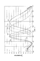
<励起特性及び発光特性の測定>
実施例1〜3の化合物について励起特性及び発光特性を測定した。励起特性及び発光特性は、分光蛍光光度計(日本分光株式会社製FP−6500)を用いて測定した。<Measurement of excitation and emission characteristics>
Excitation characteristics and emission characteristics of the compounds of Examples 1 to 3 were measured. Excitation characteristics and emission characteristics were measured using a spectrofluorometer (FP-6500 manufactured by JASCO Corporation).
図6は、実施例1〜3の化合物の励起スペクトル及び発光スペクトルを示すグラフである。具体的には、図6に、実施例1の化合物0.1(Lu0.97Ce0.03)2CaMg2Si3O12・0.9(Y0.98Ce0.02)3Al5O12の発光スペクトルを21a、励起スペクトルを22aとして示す。また、図6に、実施例2の化合物0.5(Lu0.97Ce0.03)2CaMg2Si3O12・0.5(Y0.98Ce0.02)3Al5O12の発光スペクトルを21b、励起スペクトルを22bとして示す。さらに、図6に、実施例3の化合物0.9(Lu0.97Ce0.03)2CaMg2Si3O12・0.1(Y0.98Ce0.02)3Al5O12の発光スペクトルを21c、励起スペクトルを22cとして示す。FIG. 6 is a graph showing excitation spectra and emission spectra of the compounds of Examples 1 to 3. Specifically, in FIG. 6, the compound 0.1 (Lu 0.97 Ce 0.03 ) 2 CaMg 2 Si 3 O 12 · 0.9 (Y 0.98 Ce 0.02 ) 3 Al of Example 1 is shown. The emission spectrum of 5 O 12 is shown as 21a, and the excitation spectrum is shown as 22a. FIG. 6 shows the compound 0.5 (Lu 0.97 Ce 0.03 ) 2 CaMg 2 Si 3 O 12 · 0.5 (Y 0.98 Ce 0.02 ) 3 Al 5 O 12 of Example 2. The emission spectrum is shown as 21b and the excitation spectrum as 22b. Further, in FIG. 6, the compound 0.9 (Lu 0.97 Ce 0.03 ) 2 CaMg 2 Si 3 O 12 · 0.1 (Y 0.98 Ce 0.02 ) 3 Al 5 O 12 of Example 3 is shown. The emission spectrum is shown as 21c and the excitation spectrum as 22c.
なお、励起ピーク波長は発光スペクトル測定時の励起波長とし、発光ピーク波長は励起スペクトル測定時のモニタ波長とした。また、図6の発光スペクトル及び励起スペクトルは、いずれもピーク値を1として規格化して示したものになっている。 The excitation peak wavelength was the excitation wavelength when measuring the emission spectrum, and the emission peak wavelength was the monitor wavelength when measuring the excitation spectrum. Further, the emission spectrum and the excitation spectrum in FIG. 6 are both normalized and shown with a peak value of 1.
図6より、実施例1〜3の蛍光体の励起スペクトルは、青色の波長領域に励起強度の最大値を有することが分かった。具体的には、実施例1〜3の蛍光体の励起スペクトルは、いずれも453nmに励起強度の最大値を有している。これらの結果より、実施例1〜3の蛍光体は青色光が照射されると強く発光することが分かった。 From FIG. 6, it was found that the excitation spectra of the phosphors of Examples 1 to 3 had the maximum excitation intensity in the blue wavelength region. Specifically, the excitation spectra of the phosphors of Examples 1 to 3 all have a maximum excitation intensity at 453 nm. From these results, it was found that the phosphors of Examples 1 to 3 emitted light strongly when irradiated with blue light.
また、図6より、実施例1〜3の蛍光体の発光スペクトルは、Ce3+の電子エネルギー遷移に由来するスペクトル成分を含んでいることが分かった。実施例1〜3の蛍光体の発光スペクトルは、Ce3+の電子エネルギー遷移に由来する発光スペクトルを主体とする形状になっているからである。Moreover, it turned out that the emission spectrum of the fluorescent substance of Examples 1-3 contains the spectrum component originating in the electronic energy transition of Ce3 + from FIG. This is because the emission spectra of the phosphors of Examples 1 to 3 have a shape mainly composed of an emission spectrum derived from Ce 3+ electron energy transition.
そして、図6より、実施例1〜3の蛍光体の発光スペクトルは、各々、554nm、570nm及び597nmに発光ピークを有することが分かった。これらの結果より、実施例1〜3の蛍光体が、Y3Al2(AlO4)3:Ce3+蛍光体よりも発光ピーク波長が相対的に長い、蛍光体であることが分かった。6 that the emission spectra of the phosphors of Examples 1 to 3 have emission peaks at 554 nm, 570 nm, and 597 nm, respectively. From these results, it was found that the phosphors of Examples 1 to 3 were phosphors having a relatively longer emission peak wavelength than the Y 3 Al 2 (AlO 4 ) 3 : Ce 3+ phosphor.
図4〜6より、(1−x)(Y0.98Ce0.02)3Al2(AlO4)3・x(Lu0.97Ce0.03)2CaMg2(SiO4)3で表される蛍光体が、554nm以上597nm未満の範囲内で発光ピークを制御できることが分かった。(1−x)(Y0.98Ce0.02)3Al2(AlO4)3・x(Lu0.97Ce0.03)2CaMg2(SiO4)3で表される蛍光体は、照明の演色性の向上に有用な560nm以上590nm未満の範囲内で発光ピークを制御することが容易である。4 to 6, (1-x) (Y 0.98 Ce 0.02 ) 3 Al 2 (AlO 4 ) 3 × x (Lu 0.97 Ce 0.03 ) 2 CaMg 2 (SiO 4 ) 3 It was found that the phosphor represented can control the emission peak within the range of 554 nm or more and less than 597 nm. The phosphor represented by (1-x) (Y 0.98 Ce 0.02 ) 3 Al 2 (AlO 4 ) 3 x (Lu 0.97 Ce 0.03 ) 2 CaMg 2 (SiO 4 ) 3 is It is easy to control the emission peak within the range of 560 nm to less than 590 nm, which is useful for improving the color rendering properties of illumination.
以上の実施例1〜3の結果により、母体ガーネット化合物は、端成分Y3Al2(AlO4)3が、端成分Lu2CaMg2(SiO4)3と全域固溶したものであることが分かった。また、以上の実施例1〜3の結果により、母体ガーネット化合物中にCe3+が含まれてなる蛍光体の発光ピーク波長を、535nm以上610nm未満、特に545nm以上590nm未満に制御することができることが分かった。From the results of Examples 1 to 3, the base garnet compound is such that the end component Y 3 Al 2 (AlO 4 ) 3 is solid-dissolved with the end component Lu 2 CaMg 2 (SiO 4 ) 3 in the entire region. I understood. Further, according to the results of Examples 1 to 3 above, the emission peak wavelength of the phosphor in which Ce 3+ is contained in the base garnet compound can be controlled to be 535 nm or more and less than 610 nm, particularly 545 nm or more and less than 590 nm. I understood.
[実施例4〜6]
各原料の配合割合を表1に示すように変えた以外は実施例1と同様にして、0.1(Lu0.97Ce0.03)2CaMg2Si3O12・0.9(Lu0.98Ce0.02)3Al5O12を得た(実施例4)。
また、各原料の配合割合を表1に示すように変えた以外は実施例1と同様にして、0.5(Lu0.97Ce0.03)2CaMg2Si3O12・0.5(Lu0.98Ce0.02)3Al5O12を得た(実施例5)。
さらに、各原料の配合割合を表1に示すように変えた以外は実施例1と同様にして、0.9(Lu0.97Ce0.03)2CaMg2Si3O12・0.1(Lu0.98Ce0.02)3Al5O12を得た(実施例6)。[Examples 4 to 6]
0.1 (Lu 0.97 Ce 0.03 ) 2 CaMg 2 Si 3 O 12 · 0.9 (Lu) in the same manner as in Example 1 except that the blending ratio of each raw material was changed as shown in Table 1. 0.98 Ce 0.02 ) 3 Al 5 O 12 was obtained (Example 4).
Further, except that the blending ratio of each raw material was changed as shown in Table 1 in the same manner as in Example 1, 0.5 (Lu 0.97 Ce 0.03 ) 2
Further, 0.9 (Lu 0.97 Ce 0.03 ) 2 CaMg 2 Si 3 O 12 · 0.1 was performed in the same manner as in Example 1 except that the blending ratio of each raw material was changed as shown in Table 1. (Lu 0.98 Ce 0.02 ) 3 Al 5 O 12 was obtained (Example 6).
(実施例4〜6の評価)
実施例4〜6の化合物について、実施例1と同様にして、結晶構造解析、紫外線照射試験、及び励起特性及び発光特性の測定を行った。(Evaluation of Examples 4 to 6)
About the compound of Examples 4-6, it carried out similarly to Example 1, and measured the crystal structure analysis, the ultraviolet irradiation test, and the excitation characteristic and the light emission characteristic.
<結晶構造解析>
図7は、実施例4〜6の化合物及び公知の化合物のX線回折(XRD)パターンを示すグラフである。<Crystal structure analysis>
FIG. 7 is a graph showing X-ray diffraction (XRD) patterns of the compounds of Examples 4 to 6 and known compounds.
図7において、実施例4のXRDパターンを(e)、実施例5のXRDパターンを(f)、実施例6のXRDパターンを(g)として示す。また、参考のために、PDF(Power Diffraction Files)に登録されているAl5Y3O12のパターン(PDF No.33−0040)を(d)として示す。In FIG. 7, the XRD pattern of Example 4 is shown as (e), the XRD pattern of Example 5 is shown as (f), and the XRD pattern of Example 6 is shown as (g). For reference, a pattern (PDF No. 33-0040) of Al 5 Y 3 O 12 registered in PDF (Power Diffraction Files) is shown as (d).
図7に示される各パターンを比較すると次のことが分かった。すなわち、実施例4〜6のXRDパターンは、(d)で示されるAl5Y3O12のパターンと、形状面での特徴がほぼ一致していることが分かった。When the patterns shown in FIG. 7 were compared, the following was found. In other words, it was found that the XRD patterns of Examples 4 to 6 almost coincided with the characteristics of the Al 5 Y 3 O 12 pattern shown in (d) in terms of shape.
このようなXRDパターンの一致は、実施例4〜6の化合物が、Al5Y3O12と同じガーネット構造を有する化合物を主体にしてなることを示す。そして、秤量割合を考慮すると、実施例4の化合物は、化合物(Lu0.97Ce0.03)2CaMg2Si3O12と化合物(Lu0.98Ce0.02)3Al5O12の固溶体であるといえる。実施例4の化合物の具体的組成は、0.1(Lu0.97Ce0.03)2CaMg2Si3O12・0.9(Lu0.98Ce0.02)3Al5O12であるといえる。Such coincidence of XRD patterns indicates that the compounds of Examples 4 to 6 are mainly composed of a compound having the same garnet structure as Al 5 Y 3 O 12 . In consideration of the weighing ratio, the compound of Example 4 is composed of the compound (Lu 0.97 Ce 0.03 ) 2 CaMg 2 Si 3 O 12 and the compound (Lu 0.98 Ce 0.02 ) 3 Al 5 O 12. It can be said that it is a solid solution. The specific composition of the compound of Example 4 is 0.1 (Lu 0.97 Ce 0.03 ) 2 CaMg 2 Si 3 O 12 · 0.9 (Lu 0.98 Ce 0.02 ) 3 Al 5 O 12 You can say that.
また、実施例5の化合物は、化合物(Lu0.97Ce0.03)2CaMg2Si3O12と化合物(Lu0.98Ce0.02)3Al5O12の固溶体であるといえる。実施例5の化合物の具体的組成は、0.5(Lu0.97Ce0.03)2CaMg2Si3O12・0.5(Lu0.98Ce0.02)3Al5O12であるといえる。The compound of Example 5 can be said to be a solid solution of the compound (Lu 0.97 Ce 0.03 ) 2 CaMg 2 Si 3 O 12 and the compound (Lu 0.98 Ce 0.02 ) 3 Al 5 O 12. . The specific composition of the compound of Example 5 is 0.5 (Lu 0.97 Ce 0.03 ) 2 CaMg 2 Si 3 O 12 · 0.5 (Lu 0.98 Ce 0.02 ) 3 Al 5 O 12 You can say that.
さらに、実施例6の化合物は、化合物(Lu0.97Ce0.03)2CaMg2Si3O12と化合物(Lu0.98Ce0.02)3Al5O12の固溶体であるといえる。実施例6の化合物の具体的組成は、0.9(Lu0.97Ce0.03)2CaMg2Si3O12・0.1(Lu0.98Ce0.02)3Al5O12であるといえる。Furthermore, it can be said that the compound of Example 6 is a solid solution of the compound (Lu 0.97 Ce 0.03 ) 2 CaMg 2 Si 3 O 12 and the compound (Lu 0.98 Ce 0.02 ) 3 Al 5 O 12. . The specific composition of the compound of Example 6 is 0.9 (Lu 0.97 Ce 0.03 ) 2 CaMg 2 Si 3 O 12 · 0.1 (Lu 0.98 Ce 0.02 ) 3 Al 5 O 12 You can say that.
図8は、実施例4〜6並びに比較例2及び5の化合物における、(420)面のd値と固溶量xとの関係を示すグラフである。具体的には、図8は、上記化合物を、(1−x)(Lu0.98Ce0.02)3Al2(AlO4)3・x(Lu0.97Ce0.03)2CaMg2(SiO4)3で表される固溶体として表したときのxとd値との関係を示すグラフである。(420)面のd値とは、隣接する(420)面の間隔である。
図8のグラフは、以下のようにして作成した。はじめに、化合物のXRDパターンの33°付近の主ピーク((420)面の回折線)のXRD回折角(2θ)をもとに、各化合物の(420)面のd値を算出した。次に、各化合物のd値と、各化合物の(1−x)(Lu0.98Ce0.02)3Al2(AlO4)3・x(Lu0.97Ce0.03)2CaMg2(SiO4)3で表される組成とに基づき、xとd値との関係を示すグラフを作成した。
なお、比較例2の化合物のXRDパターンは、実施例1〜3と同様のX線回折装置を用いて測定した。FIG. 8 is a graph showing the relationship between the d value of the (420) plane and the solid solution amount x in the compounds of Examples 4 to 6 and Comparative Examples 2 and 5. Specifically, FIG. 8 shows that the above compound is (1-x) (Lu 0.98 Ce 0.02 ) 3 Al 2 (AlO 4 ) 3 × x (Lu 0.97 Ce 0.03 ) 2 CaMg. 2 is a graph showing the relationship between x and d values when expressed as a solid solution represented by (SiO 4) 3. The d value of the (420) plane is the interval between adjacent (420) planes.
The graph of FIG. 8 was created as follows. First, the d value of the (420) plane of each compound was calculated based on the XRD diffraction angle (2θ) of the main peak (diffracted line of (420) plane) near 33 ° of the XRD pattern of the compound. Next, the d value of each compound and (1-x) (Lu 0.98 Ce 0.02 ) 3 Al 2 (AlO 4 ) 3 · x (Lu 0.97 Ce 0.03 ) 2 CaMg of each compound Based on the composition represented by 2 (SiO 4 ) 3 , a graph showing the relationship between x and d value was prepared.
In addition, the XRD pattern of the compound of the comparative example 2 was measured using the same X-ray diffractometer as Examples 1-3.
図8に示されるように、d値はxにほぼ比例して増加することが分かった。すなわち、図8より、xを増すにつれて、蛍光体の(420)面の面間隔が連続的に大きくなることが分かった。 As shown in FIG. 8, it has been found that the d value increases almost in proportion to x. That is, FIG. 8 shows that the surface spacing of the (420) plane of the phosphor increases continuously as x increases.
このようにd値がxにほぼ比例して増加するため、図7及び図8は、化合物(Lu0.97Ce0.03)2CaMg2Si3O12と、化合物(Lu0.98Ce0.02)3Al5O12とが、固溶体を形成することを示すデータであるといえる。Thus, since the d value increases almost in proportion to x, FIGS. 7 and 8 show that the compound (Lu 0.97 Ce 0.03 ) 2 CaMg 2 Si 3 O 12 and the compound (Lu 0.98 Ce) 0.02 ) 3 Al 5 O 12 is data indicating that a solid solution is formed.
また、図7及び図8に示す解析結果は、発光中心としてCe3+を少なくとも含む蛍光体であって、端成分Lu3Al2(AlO4)3と端成分Lu2CaMg2(SiO4)3との固溶体を母体とする蛍光体の存在とこの蛍光体の合成事実とを示すものである。ここで、端成分Lu3Al2(AlO4)3と端成分Lu2CaMg2(SiO4)3との固溶体とは、具体的には(1−x)Lu3Al2(AlO4)3・xLu2CaMg2(SiO4)3で表される化合物である。The analysis results shown in FIG. 7 and FIG. 8 are phosphors containing at least Ce 3+ as the emission center, and the end component Lu 3 Al 2 (AlO 4 ) 3 and the end component Lu 2 CaMg 2 (SiO 4 ) 3. The presence of a phosphor having a solid solution as a base and the fact of synthesis of this phosphor are shown. Here, the solid solution of the end component Lu 3 Al 2 (AlO 4 ) 3 and the end component Lu 2 CaMg 2 (SiO 4 ) 3 is specifically (1-x) Lu 3 Al 2 (AlO 4 ) 3. XLu 2 CaMg 2 (SiO 4 ) 3 is a compound represented by
なお、このような固溶体は従来知られておらず、また従来技術から予測できるものでもない。このような固溶体は、実験検証によってはじめて確認できるものである。 In addition, such a solid solution is not conventionally known and cannot be predicted from the prior art. Such a solid solution can be confirmed only by experimental verification.
<紫外線照射試験>
実施例4〜6の化合物に紫外線(波長365nm)を照射する紫外線照射試験を行った。<Ultraviolet irradiation test>
The ultraviolet irradiation test which irradiates an ultraviolet-ray (wavelength 365nm) to the compound of Examples 4-6 was done.
実施例4の化合物に紫外線(波長365nm)を照射したところ、緑色の蛍光が目視観察された。すなわち、実施例4の化合物は黄緑色光を放射する蛍光体であった。 When the compound of Example 4 was irradiated with ultraviolet rays (wavelength 365 nm), green fluorescence was visually observed. That is, the compound of Example 4 was a phosphor emitting yellow-green light.
実施例5の化合物に紫外線(波長365nm)を照射したところ、黄色の蛍光が目視観察された。すなわち、実施例5の化合物は黄色光を放射する蛍光体であった。 When the compound of Example 5 was irradiated with ultraviolet rays (wavelength 365 nm), yellow fluorescence was visually observed. That is, the compound of Example 5 was a phosphor emitting yellow light.
実施例6の化合物に紫外線(波長365nm)を照射したところ、橙色の蛍光が目視観察された。すなわち、実施例6の化合物は橙色光を放射する蛍光体であった。 When the compound of Example 6 was irradiated with ultraviolet rays (wavelength 365 nm), orange fluorescence was visually observed. That is, the compound of Example 6 was a phosphor emitting orange light.
<励起特性及び発光特性の測定>
実施例4〜6の化合物について実施例1と同様にして励起特性及び発光特性を測定した。<Measurement of excitation and emission characteristics>
Excitation characteristics and emission characteristics of the compounds of Examples 4 to 6 were measured in the same manner as in Example 1.
図9は、実施例4〜6の化合物の励起スペクトル及び発光スペクトルを示すグラフである。具体的には、図9に、実施例4の化合物0.1(Lu0.97Ce0.03)2CaMg2Si3O12・0.9(Lu0.98Ce0.02)3Al5O12の発光スペクトルを21d、励起スペクトルを22dとして示す。また、図9に、実施例5の化合物0.5(Lu0.97Ce0.03)2CaMg2Si3O12・0.5(Lu0.98Ce0.02)3Al5O12の発光スペクトルを21e、励起スペクトルを22eとして示す。さらに、図9に、実施例6の化合物0.9(Lu0.97Ce0.03)2CaMg2Si3O12・0.1(Lu0.98Ce0.02)3Al5O12の発光スペクトルを21f、励起スペクトルを22fとして示す。FIG. 9 is a graph showing excitation spectra and emission spectra of the compounds of Examples 4 to 6. Specifically, in FIG. 9, the compound 0.1 (Lu 0.97 Ce 0.03 ) 2 CaMg 2 Si 3 O 12 · 0.9 (Lu 0.98 Ce 0.02 ) 3 Al of Example 4 is shown. The emission spectrum of 5 O 12 is shown as 21d, and the excitation spectrum is shown as 22d. Further, in FIG. 9, the compound 0.5 (Lu 0.97 Ce 0.03 ) 2 CaMg 2 Si 3 O 12 · 0.5 (Lu 0.98 Ce 0.02 ) 3 Al 5 O 12 of Example 5 is used. The emission spectrum is shown as 21e and the excitation spectrum as 22e. Further, FIG. 9 shows that the compound 0.9 (Lu 0.97 Ce 0.03 ) 2 CaMg 2 Si 3 O 12 · 0.1 (Lu 0.98 Ce 0.02 ) 3 Al 5 O 12 of Example 6 is used. The emission spectrum is shown as 21f and the excitation spectrum as 22f.
なお、励起ピーク波長は発光スペクトル測定時の励起波長とし、発光ピーク波長は励起スペクトル測定時のモニタ波長とした。また、図9の発光スペクトル及び励起スペクトルは、いずれもピーク値を1として規格化して示したものになっている。 The excitation peak wavelength was the excitation wavelength when measuring the emission spectrum, and the emission peak wavelength was the monitor wavelength when measuring the excitation spectrum. Further, the emission spectrum and the excitation spectrum in FIG. 9 are both normalized and shown with a peak value of 1.
図9より、実施例4〜6の蛍光体の励起スペクトルは、青色の波長領域に励起強度の最大値を有することが分かった。具体的には、実施例4〜6の蛍光体の励起スペクトルは、それぞれ446nm(実施例4)、448nm(実施例5)及び457nm(実施例6)に励起強度の最大値を有している。これらの結果より、実施例4〜6の蛍光体は青色光が照射されると強く発光することが分かった。 From FIG. 9, it was found that the excitation spectra of the phosphors of Examples 4 to 6 had the maximum excitation intensity in the blue wavelength region. Specifically, the excitation spectra of the phosphors of Examples 4 to 6 have maximum excitation intensity values at 446 nm (Example 4), 448 nm (Example 5), and 457 nm (Example 6), respectively. . From these results, it was found that the phosphors of Examples 4 to 6 emitted strong light when irradiated with blue light.
また、図9より、実施例4〜6の蛍光体の発光スペクトルは、Ce3+の電子エネルギー遷移に由来するスペクトル成分を含んでいることが分かった。実施例4〜6の蛍光体の発光スペクトルは、Ce3+の電子エネルギー遷移に由来する発光スペクトルを主体とする形状になっているからである。Moreover, it turned out that the emission spectrum of the fluorescent substance of Examples 4-6 contains the spectral component derived from the electronic energy transition of Ce3 + from FIG. This is because the emission spectra of the phosphors of Examples 4 to 6 have a shape mainly composed of an emission spectrum derived from Ce 3+ electron energy transition.
そして、図9より、実施例4〜6の蛍光体の発光スペクトルは、525nm、558nm及び596nmに発光ピークを有することが分かった。これらの結果より、実施例4〜6の蛍光体が、Lu3Al2(AlO4)3:Ce3+蛍光体よりも発光ピーク波長が相対的に長い、蛍光体であることが分かった。9 that the emission spectra of the phosphors of Examples 4 to 6 have emission peaks at 525 nm, 558 nm, and 596 nm. From these results, it was found that the phosphors of Examples 4 to 6 were phosphors having an emission peak wavelength relatively longer than that of the Lu 3 Al 2 (AlO 4 ) 3 : Ce 3+ phosphor.
図7〜9より、(1−x)(Lu0.98Ce0.02)3Al2(AlO4)3・x(Lu0.97Ce0.03)2CaMg2(SiO4)3で表される蛍光体が、525nm以上596nm未満の範囲内で発光ピークを制御できることが分かった。(1−x)(Lu0.98Ce0.02)3Al2(AlO4)3・x(Lu0.97Ce0.03)2CaMg2(SiO4)3で表される蛍光体は、照明の演色性の向上に有用な560nm以上590nm未満の範囲内で発光ピークを制御することが容易である。From 7 to 9, in (1-x) (Lu 0.98 Ce 0.02) 3 Al 2 (AlO 4) 3 · x (Lu 0.97 Ce 0.03) 2 CaMg 2 (SiO 4) 3 It was found that the phosphor represented can control the emission peak within the range of 525 nm or more and less than 596 nm. The phosphor represented by (1-x) (Lu 0.98 Ce 0.02 ) 3 Al 2 (AlO 4 ) 3 × x (Lu 0.97 Ce 0.03 ) 2 CaMg 2 (SiO 4 ) 3 is It is easy to control the emission peak within the range of 560 nm to less than 590 nm, which is useful for improving the color rendering properties of illumination.
以上の実施例4〜6の結果により、母体ガーネット化合物は、端成分Lu3Al2(AlO4)3が、端成分Lu2CaMg2(SiO4)3と全域固溶したものであることが分かった。また、以上の実施例4〜6の結果により、母体ガーネット化合物中にCe3+が含まれてなる蛍光体の発光ピーク波長を、515nm以上610nm未満、特に525nm以上590nm未満に制御することができることが分かった。From the results of Examples 4 to 6, the parent garnet compound is such that the end component Lu 3 Al 2 (AlO 4 ) 3 is solid-dissolved with the end component Lu 2 CaMg 2 (SiO 4 ) 3 in the entire region. I understood. In addition, according to the results of Examples 4 to 6 described above, the emission peak wavelength of the phosphor containing Ce 3+ in the base garnet compound can be controlled to be 515 nm or more and less than 610 nm, particularly 525 nm or more and less than 590 nm. I understood.
[実施例7〜10]
各原料の配合割合を表1に示すように変えた以外は実施例1と同様にして、0.1(Lu0.97Ce0.03)2(Ca0.9Mg0.1)Mg2Si3O12・0.9(Lu0.98Ce0.02)3Al5O12を得た(実施例7)。
また、各原料の配合割合を表1に示すように変えた以外は実施例1と同様にして、0.5(Lu0.97Ce0.03)2(Ca0.9Mg0.1)Mg2Si3O12・0.5(Lu0.98Ce0.02)3Al5O12を得た(実施例8)。
さらに、各原料の配合割合を表1に示すように変えた以外は実施例1と同様にして、0.9(Lu0.97Ce0.03)2(Ca0.9Mg0.1)Mg2Si3O12・0.1(Lu0.98Ce0.02)3Al5O12を得た(実施例9)。
また、各原料の配合割合を表1に示すように変えた以外は実施例1と同様にして、(Lu0.97Ce0.03)2(Ca0.9Mg0.1)Mg2Si3O12を得た(実施例10)。[Examples 7 to 10]
0.1 (Lu 0.97 Ce 0.03 ) 2 (Ca 0.9 Mg 0.1 ) Mg 2 in the same manner as in Example 1 except that the blending ratio of each raw material was changed as shown in Table 1. was obtained Si 3 O 12 · 0.9 (Lu 0.98 Ce 0.02) 3 Al 5 O 12 ( example 7).
Further, 0.5 (Lu 0.97 Ce 0.03 ) 2 (Ca 0.9 Mg 0.1 ) was carried out in the same manner as in Example 1 except that the blending ratio of each raw material was changed as shown in Table 1. Mg 2 Si 3 O 12 · 0.5 (Lu 0.98 Ce 0.02 ) 3 Al 5 O 12 was obtained (Example 8).
Further, 0.9 (Lu 0.97 Ce 0.03 ) 2 (Ca 0.9 Mg 0.1 ) was carried out in the same manner as in Example 1 except that the blending ratio of each raw material was changed as shown in Table 1. Mg 2 Si 3 O 12 · 0.1 (Lu 0.98 Ce 0.02 ) 3 Al 5 O 12 was obtained (Example 9).
Further, except that the blending ratio of each raw material was changed as shown in Table 1 in the same manner as in Example 1, (Lu 0.97 Ce 0.03) 2 (Ca 0.9 Mg 0.1)
(実施例7〜10の評価)
実施例7〜10の化合物について、実施例1と同様にして、結晶構造解析、紫外線照射試験、及び発光特性の測定を行った。(Evaluation of Examples 7 to 10)
About the compound of Examples 7-10, it carried out similarly to Example 1, and performed the crystal structure analysis, the ultraviolet irradiation test, and the measurement of the luminescent property.
<結晶構造解析>
図10は、実施例7〜10の化合物及び公知の化合物のX線回折(XRD)パターンを示すグラフである。<Crystal structure analysis>
FIG. 10 is a graph showing X-ray diffraction (XRD) patterns of the compounds of Examples 7 to 10 and known compounds.
図10において、実施例7のXRDパターンを(h)、実施例8のXRDパターンを(i)、実施例9のXRDパターンを(j)、実施例10のXRDパターンを(k)として示す。また、参考のために、PDF(Power Diffraction Files)に登録されているAl5Y3O12のパターン(PDF No.33−0040)を(d)として示す。10, the XRD pattern of Example 7 is shown as (h), the XRD pattern of Example 8 is shown as (i), the XRD pattern of Example 9 is shown as (j), and the XRD pattern of Example 10 is shown as (k). For reference, a pattern (PDF No. 33-0040) of Al 5 Y 3 O 12 registered in PDF (Power Diffraction Files) is shown as (d).
図10に示される各パターンを比較すると次のことが分かった。すなわち、実施例7〜10のXRDパターンは、(d)で示されるAl5Y3O12のパターンと、形状面での特徴がほぼ一致していることが分かった。When the patterns shown in FIG. 10 were compared, the following was found. In other words, it was found that the XRD patterns of Examples 7 to 10 were almost identical in feature with respect to the shape of Al 5 Y 3 O 12 shown in (d).
このようなXRDパターンの一致は、実施例7〜10の化合物が、Al5Y3O12と同じガーネット構造を有する化合物を主体にしてなることを示す。そして、秤量割合を考慮すると、実施例7の化合物は、化合物(Lu0.97Ce0.03)2(Ca0.9Mg0.1)Mg2Si3O12と化合物(Lu0.98Ce0.02)3Al5O12の固溶体であるといえる。実施例7の化合物の具体的組成は、0.1(Lu0.97Ce0.03)2(Ca0.9Mg0.1)Mg2Si3O12・0.9(Lu0.98Ce0.02)3Al5O12であるといえる。Such coincidence of XRD patterns indicates that the compounds of Examples 7 to 10 are mainly composed of a compound having the same garnet structure as Al 5 Y 3 O 12 . In consideration of the weighing ratio, the compound of Example 7 is composed of the compound (Lu 0.97 Ce 0.03 ) 2 (Ca 0.9 Mg 0.1 ) Mg 2 Si 3 O 12 and the compound (Lu 0.98). It can be said that it is a solid solution of Ce 0.02 ) 3 Al 5 O 12 . The specific composition of the compound of Example 7 is 0.1 (Lu 0.97 Ce 0.03 ) 2 (Ca 0.9 Mg 0.1 ) Mg 2 Si 3 O 12 · 0.9 (Lu 0.98 It said to ce 0.02) a 3 Al 5 O 12.
また、実施例8の化合物は、化合物(Lu0.97Ce0.03)2(Ca0.9Mg0.1)Mg2Si3O12と化合物(Lu0.98Ce0.02)3Al5O12の固溶体であるといえる。実施例8の化合物の具体的組成は、0.5(Lu0.97Ce0.03)2(Ca0.9Mg0.1)Mg2Si3O12・0.5(Lu0.98Ce0.02)3Al5O12であるといえる。The compound of Example 8, compound (Lu 0.97 Ce 0.03) 2 ( Ca 0.9 Mg 0.1)
さらに、実施例9の化合物は、化合物(Lu0.97Ce0.03)2(Ca0.9Mg0.1)Mg2Si3O12と化合物(Lu0.98Ce0.02)3Al5O12の固溶体であるといえる。実施例9の化合物の具体的組成は、0.9(Lu0.97Ce0.03)2(Ca0.9Mg0.1)Mg2Si3O12・0.1(Lu0.98Ce0.02)3Al5O12であるといえる。Further, the compound of Example 9 is composed of the compound (Lu 0.97 Ce 0.03 ) 2 (Ca 0.9 Mg 0.1 ) Mg 2 Si 3 O 12 and the compound (Lu 0.98 Ce 0.02 ) 3. It can be said that it is a solid solution of Al 5 O 12 . The specific composition of the compound of Example 9 is 0.9 (Lu 0.97 Ce 0.03 ) 2 (Ca 0.9 Mg 0.1 ) Mg 2 Si 3 O 12 · 0.1 (Lu 0.98 It said to ce 0.02) a 3 Al 5 O 12.
また、実施例10の化合物の具体的組成は、(Lu0.97Ce0.03)2(Ca0.9Mg0.1)Mg2Si3O12であるといえる。Further, specific composition of the compound of Example 10 can be said to be (Lu 0.97 Ce 0.03) 2 ( Ca 0.9 Mg 0.1)
図11は、実施例7〜10並びに比較例2の化合物における、(420)面のd値と固溶量xとの関係を示すグラフである。具体的には、図11は上記化合物を(1−x)(Lu0.98Ce0.02)3Al2(AlO4)3・x(Lu0.97Ce0.03)2(Ca0.9Mg0.1)Mg2(SiO4)3で表される固溶体として表したときのxとd値との関係を示すグラフである。(420)面のd値とは、隣接する(420)面の間隔である。
図11のグラフは、以下のようにして作成した。はじめに、化合物のXRDパターンの33°付近の主ピーク((420)面の回折線)のXRD回折角(2θ)をもとに、各化合物の(420)面のd値を算出した。次に、各化合物のd値と、各化合物の(1−x)(Lu0.98Ce0.02)3Al2(AlO4)3・x(Lu0.97Ce0.03)2(Ca0.9Mg0.1)Mg2(SiO4)3で表される組成とに基づき、xとd値との関係を示すグラフを作成した。FIG. 11 is a graph showing the relationship between the d value on the (420) plane and the solid solution amount x in the compounds of Examples 7 to 10 and Comparative Example 2. Specifically, FIG. 11 shows that the compound is (1-x) (Lu 0.98 Ce 0.02 ) 3 Al 2 (AlO 4 ) 3 × x (Lu 0.97 Ce 0.03 ) 2 (Ca 0 .9 Mg 0.1 ) Mg 2 (SiO 4 ) 3 is a graph showing the relationship between x and d values when expressed as a solid solution. The d value of the (420) plane is the interval between adjacent (420) planes.
The graph of FIG. 11 was created as follows. First, the d value of the (420) plane of each compound was calculated based on the XRD diffraction angle (2θ) of the main peak (diffracted line of (420) plane) near 33 ° of the XRD pattern of the compound. Next, the d value of each compound and (1-x) (Lu 0.98 Ce 0.02 ) 3 Al 2 (AlO 4 ) 3 · x (Lu 0.97 Ce 0.03 ) 2 ( Based on the composition represented by Ca 0.9 Mg 0.1 ) Mg 2 (SiO 4 ) 3 , a graph showing the relationship between x and d value was created.
図11に示されるように、d値はxにほぼ比例して増加することが分かった。すなわち、図11より、xを増すにつれて、蛍光体の(420)面の面間隔が連続的に大きくなることが分かった。 As shown in FIG. 11, it was found that the d value increases almost in proportion to x. That is, FIG. 11 shows that the surface spacing of the (420) plane of the phosphor increases continuously as x increases.
このように図11ではd値がxにほぼ比例して増加する。このため、図10及び図11は、化合物(Lu0.97Ce0.03)2(Ca0.9Mg0.1)Mg2Si3O12と、化合物(Lu0.98Ce0.02)3Al5O12とが、固溶体を形成することを示すデータであるといえる。Thus, in FIG. 11, the d value increases in proportion to x. For this reason, FIG. 10 and FIG. 11 show the compound (Lu 0.97 Ce 0.03 ) 2 (Ca 0.9 Mg 0.1 ) Mg 2 Si 3 O 12 and the compound (Lu 0.98 Ce 0.02). ) and 3 Al 5 O 12 is said to be data indicating the formation of a solid solution.
また、図10及び図11に示す解析結果は、発光中心としてCe3+を少なくとも含む蛍光体であって、端成分Lu3Al2(AlO4)3と端成分Lu2(Ca0.9Mg0.1)Mg2Si3O12との固溶体を母体とする蛍光体の存在を示すものである。さらに、図10及び図11に示す解析結果は、この蛍光体の合成事実を示すものである。ここで、端成分Lu3Al2(AlO4)3と端成分Lu2(Ca0.9Mg0.1)Mg2(SiO4)3との固溶体とは、具体的には(1−x)Lu3Al2(AlO4)3・xLu2(Ca0.9Mg0.1)Mg2Si3O12で表される化合物である。Further, the analysis results shown in FIGS. 10 and 11 are phosphors containing at least Ce 3+ as the emission center, and the end component Lu 3 Al 2 (AlO 4 ) 3 and the end component Lu 2 (Ca 0.9 Mg 0). .1 ) The presence of a phosphor having a solid solution with Mg 2 Si 3 O 12 as a base. Furthermore, the analysis results shown in FIG. 10 and FIG. 11 show the synthesis fact of this phosphor. Here, the solid solution of the end component Lu 3 Al 2 (AlO 4 ) 3 and the end component Lu 2 (Ca 0.9 Mg 0.1 ) Mg 2 (SiO 4 ) 3 is specifically (1-x ) Lu 3 Al 2 (AlO 4 ) 3 xLu 2 (Ca 0.9 Mg 0.1 ) Mg 2 Si 3 O 12
<紫外線照射試験>
実施例7〜10の化合物に紫外線(波長365nm)を照射する紫外線照射試験を行った。<Ultraviolet irradiation test>
The ultraviolet irradiation test which irradiates an ultraviolet-ray (wavelength 365nm) to the compound of Examples 7-10 was done.
実施例7の化合物に紫外線(波長365nm)を照射したところ、緑色の蛍光が目視観察された。すなわち、実施例7の化合物は緑色光を放射する蛍光体であった。 When the compound of Example 7 was irradiated with ultraviolet rays (wavelength 365 nm), green fluorescence was visually observed. That is, the compound of Example 7 was a phosphor emitting green light.
実施例8の化合物に紫外線(波長365nm)を照射したところ、黄色の蛍光が目視観察された。すなわち、実施例8の化合物は黄色光を放射する蛍光体であった。 When the compound of Example 8 was irradiated with ultraviolet rays (wavelength 365 nm), yellow fluorescence was visually observed. That is, the compound of Example 8 was a phosphor emitting yellow light.
実施例9の化合物に紫外線(波長365nm)を照射したところ、橙色の蛍光が目視観察された。すなわち、実施例9の化合物は橙色光を放射する蛍光体であった。 When the compound of Example 9 was irradiated with ultraviolet rays (wavelength 365 nm), orange fluorescence was visually observed. That is, the compound of Example 9 was a phosphor emitting orange light.
実施例10の化合物に紫外線(波長365nm)を照射したところ、橙色の蛍光が目視観察された。すなわち、実施例10の化合物は橙色光を放射する蛍光体であった。 When the compound of Example 10 was irradiated with ultraviolet rays (wavelength 365 nm), orange fluorescence was visually observed. That is, the compound of Example 10 was a phosphor emitting orange light.
<発光特性の測定>
実施例7〜10の化合物について実施例1と同様にして発光特性を測定した。<Measurement of luminous characteristics>
The light emission characteristics of the compounds of Examples 7 to 10 were measured in the same manner as in Example 1.
図12は、実施例7〜10の化合物の発光スペクトルを示すグラフである。具体的には、図12に、実施例7の化合物0.1(Lu0.97Ce0.03)2(Ca0.9Mg0.1)Mg2Si3O12・0.9(Lu0.98Ce0.02)3Al5O12の発光スペクトルを21gとして示す。また、図12に、実施例8の化合物0.5(Lu0.97Ce0.03)2(Ca0.9Mg0.1)Mg2Si3O12・0.5(Lu0.98Ce0.02)3Al5O12の発光スペクトルを21hとして示す。さらに、図12に、実施例9の化合物0.9(Lu0.97Ce0.03)2(Ca0.9Mg0.1)Mg2Si3O12・0.1(Lu0.98Ce0.02)3Al5O12の発光スペクトルを21iとして示す。さらに、図12に、実施例10の化合物(Lu0.97Ce0.03)2(Ca0.9Mg0.1)Mg2Si3O12の発光スペクトルを21jとして示す。FIG. 12 is a graph showing the emission spectra of the compounds of Examples 7 to 10. Specifically, FIG. 12 shows the compound 0.1 (Lu 0.97 Ce 0.03 ) 2 (Ca 0.9 Mg 0.1 ) Mg 2 Si 3 O 12 · 0.9 (Lu) of Example 7. The emission spectrum of 0.98 Ce 0.02 ) 3 Al 5 O 12 is shown as 21 g. In addition, FIG. 12 shows that compound 0.5 (Lu 0.97 Ce 0.03 ) 2 (Ca 0.9 Mg 0.1 ) Mg 2 Si 3 O 12 · 0.5 (Lu 0.98 ) of Example 8. The emission spectrum of Ce 0.02 ) 3 Al 5 O 12 is shown as 21h. Further, FIG. 12 shows that the compound 0.9 (Lu 0.97 Ce 0.03 ) 2 (Ca 0.9 Mg 0.1 ) Mg 2 Si 3 O 12 · 0.1 (Lu 0.98 ) of Example 9 is used. The emission spectrum of Ce 0.02 ) 3 Al 5 O 12 is shown as 21i. Further, FIG. 12 shows the emission spectrum of the compound of Example 10 (Lu 0.97 Ce 0.03 ) 2 (Ca 0.9 Mg 0.1 ) Mg 2 Si 3 O 12 as 21j.
なお、発光ピーク波長は、発光スペクトルのピーク値における波長とした。また、図12の発光スペクトルは、いずれもピーク値を1として規格化して示したものになっている。 The emission peak wavelength was the wavelength at the peak value of the emission spectrum. In addition, the emission spectra in FIG. 12 are all normalized and shown with a peak value of 1.
また、図12より、実施例7〜10の蛍光体の発光スペクトルは、Ce3+の電子エネルギー遷移に由来するスペクトル成分を含んでいることが分かった。実施例7〜10の蛍光体の発光スペクトルは、Ce3+の電子エネルギー遷移に由来する発光スペクトルを主体とする形状になっているからである。Moreover, from FIG. 12, it was found that the emission spectra of the phosphors of Examples 7 to 10 include a spectral component derived from Ce 3+ electron energy transition. This is because the emission spectra of the phosphors of Examples 7 to 10 have a shape mainly composed of the emission spectrum derived from the electron energy transition of Ce 3+ .
そして、図12より、実施例7〜10の蛍光体の発光スペクトルは、534nm、545nm、582nm及び590nmに発光ピークを有することが分かった。これらの結果より、実施例7〜10の蛍光体が、Lu3Al2(AlO4)3:Ce3+蛍光体よりも発光ピーク波長が相対的に長い、蛍光体であることが分かった。12 that the emission spectra of the phosphors of Examples 7 to 10 have emission peaks at 534 nm, 545 nm, 582 nm, and 590 nm. From these results, it was found that the phosphors of Examples 7 to 10 were phosphors having an emission peak wavelength relatively longer than that of the Lu 3 Al 2 (AlO 4 ) 3 : Ce 3+ phosphor.
図10〜12より、(1−x)(Lu0.98Ce0.02)3Al2(AlO4)3・x(Lu0.97Ce0.03)2(Ca0.9Mg0.1)Mg2(SiO4)3で表される蛍光体が、特定波長領域の発光ピークを制御できることが分かった。具体的には、上記式で表される蛍光体が、534nm以上590nm未満の範囲内で発光ピークを制御できることが分かった。上記式で表される蛍光体は、照明の演色性の向上に有用な560nm以上590nm未満の範囲内で発光ピークを制御することが容易である。10 to 12, (1-x) (Lu 0.98 Ce 0.02 ) 3 Al 2 (AlO 4 ) 3 × x (Lu 0.97 Ce 0.03 ) 2 (Ca 0.9 Mg 0. 1 ) It was found that the phosphor represented by Mg 2 (SiO 4 ) 3 can control the emission peak in a specific wavelength region. Specifically, it has been found that the phosphor represented by the above formula can control the emission peak within a range of 534 nm or more and less than 590 nm. The phosphor represented by the above formula can easily control the emission peak within the range of 560 nm or more and less than 590 nm, which is useful for improving the color rendering properties of illumination.
以上の実施例7〜10の結果により、母体ガーネット化合物は、端成分Lu3Al2(AlO4)3が、端成分Lu2(Ca0.9Mg0.1)Mg2(SiO4)3と全域固溶したものであることが分かった。また、以上の実施例7〜10の結果により、母体ガーネット化合物中にCe3+が含まれてなる蛍光体の発光ピーク波長を、515nm以上610nm未満、特に534nm以上590nm未満に制御することができることが分かった。According to the results of Examples 7 to 10 described above, the base garnet compound is composed of the end component Lu 3 Al 2 (AlO 4 ) 3 and the end component Lu 2 (Ca 0.9 Mg 0.1 ) Mg 2 (SiO 4 ) 3. It turned out that it was a solid solution. In addition, according to the results of Examples 7 to 10 described above, the emission peak wavelength of the phosphor containing Ce 3+ in the base garnet compound can be controlled to be 515 nm or more and less than 610 nm, particularly 534 nm or more and less than 590 nm. I understood.
(温度消光の評価)
実施例3、実施例6、実施例9及び比較例1〜5の蛍光体について、温度消光を評価した。温度消光は、瞬間マルチ測光システム(製品名:MCPD−9800、大塚電子株式会社製)を備える量子効率測定システム(製品名:QE−1100、大塚電子株式会社製)を用いて評価した。具体的には、量子効率測定システムが備える加熱機構を用いて、実施例3、実施例6、実施例9及び比較例1〜5の蛍光体を、30℃から200℃まで、10℃又は20℃刻みで加熱した。そして、10℃又は20℃刻みで加熱した度に、内部量子効率を測定した。(Evaluation of temperature quenching)
About the fluorescent substance of Example 3, Example 6, Example 9, and Comparative Examples 1-5, temperature quenching was evaluated. Temperature quenching was evaluated using a quantum efficiency measurement system (product name: QE-1100, manufactured by Otsuka Electronics Co., Ltd.) equipped with an instantaneous multi-photometry system (product name: MCPD-9800, manufactured by Otsuka Electronics Co., Ltd.). Specifically, using the heating mechanism provided in the quantum efficiency measurement system, the phosphors of Example 3, Example 6, Example 9, and Comparative Examples 1 to 5 were changed from 30 ° C. to 200 ° C. at 10 ° C. or 20 ° C. Heat in increments of ° C. And every time it heated at 10 degreeC or 20 degreeC increment, the internal quantum efficiency was measured.
蛍光体温度が30℃のときの内部量子効率に対する、蛍光体温度が150℃のときの内部量子効率の割合を内部量子効率維持率(%)とし、蛍光体の温度消光の尺度とした。内部量子効率維持率は、蛍光体の温度消光を評価する指標となる。内部量子効率維持率と蛍光体の温度消光とは、蛍光体の内部量子効率維持率が高いほど、蛍光体の温度消光が小さくなる関係にある。 The ratio of the internal quantum efficiency when the phosphor temperature is 150 ° C. with respect to the internal quantum efficiency when the phosphor temperature is 30 ° C. is defined as the internal quantum efficiency maintenance ratio (%), which is a measure of the temperature quenching of the phosphor. The internal quantum efficiency maintenance rate is an index for evaluating the temperature quenching of the phosphor. The internal quantum efficiency maintenance rate and the temperature quenching of the phosphor have a relationship that the temperature quenching of the phosphor becomes smaller as the internal quantum efficiency maintenance rate of the phosphor is higher.
図13は、実施例3、6及び9、並びに比較例1〜5の化合物の発光ピーク波長と内部量子効率維持率との関係を示すグラフである。 FIG. 13 is a graph showing the relationship between the emission peak wavelength of the compounds of Examples 3, 6 and 9, and Comparative Examples 1 to 5 and the internal quantum efficiency retention rate.
なお、図13に示される発光ピーク波長は、瞬間マルチ測光システムを用い、25℃の温度下で測定した各々の蛍光体の発光スペクトルの強度最大値である。 The emission peak wavelength shown in FIG. 13 is the maximum value of the emission spectrum of each phosphor measured at a temperature of 25 ° C. using an instantaneous multi-photometry system.
図13より、実施例3の蛍光体の発光ピーク波長は、比較例1の蛍光体よりも相対的に長いことが分かった。また、実施例3の蛍光体の内部量子効率維持率は、比較例3〜5の蛍光体よりも高いことが分かった。 From FIG. 13, it was found that the emission peak wavelength of the phosphor of Example 3 was relatively longer than that of the phosphor of Comparative Example 1. Moreover, it turned out that the internal quantum efficiency maintenance factor of the fluorescent substance of Example 3 is higher than the fluorescent substance of Comparative Examples 3-5.
これらの結果より、実施例3の蛍光体が、Y3Al2(AlO4)3:Ce3+蛍光体よりも発光ピーク波長が相対的に長く、同じ光色を放つ他のガーネット蛍光体と比較して温度消光が改善された、蛍光体であることが分かった。From these results, the phosphor of Example 3 is relatively longer in emission peak wavelength than the Y 3 Al 2 (AlO 4 ) 3 : Ce 3+ phosphor and is compared with other garnet phosphors that emit the same light color. Thus, the phosphor was found to have improved temperature quenching.
また、図13に示す結果より、発光中心としてCe3+を少なくとも含む蛍光体であって、端成分Y3Al2(AlO4)3と端成分Lu2CaMg2(SiO4)3との固溶体を母体とする蛍光体が、以下の特性を有することが示唆される。すなわち、上記固溶体を母体とする蛍光体は、Y3Al2(AlO4)3:Ce3+蛍光体よりも発光ピーク波長が560nm以上と相対的に長く、同じ光色を放つ他のガーネット蛍光体と比較して温度消光が改善された、蛍光体であることが示唆される。従来、このような発光ピーク波長が560nm以上になる特性と、同じ光色を放つ他のガーネット蛍光体と比較して温度消光が改善されるという特性とを両立する蛍光体は、知られていなかった。なお、端成分Y3Al2(AlO4)3と端成分Lu2CaMg2(SiO4)3との固溶体とは、具体的には(1−x)Y3Al2(AlO4)3・xLu2CaMg2(SiO4)3で表される化合物である。Further, from the results shown in FIG. 13, a phosphor containing at least Ce 3+ as the emission center, which is a solid solution of the end component Y 3 Al 2 (AlO 4 ) 3 and the end component Lu 2 CaMg 2 (SiO 4 ) 3 , It is suggested that the phosphor as a base has the following characteristics. That is, the phosphor having the solid solution as a base is other garnet phosphor that emits the same light color with a relatively longer emission peak wavelength of 560 nm or more than the Y 3 Al 2 (AlO 4 ) 3 : Ce 3+ phosphor. This suggests that the phosphor has an improved temperature quenching compared to the above. Conventionally, there has not been known a phosphor that has such a characteristic that the emission peak wavelength is 560 nm or more and a characteristic that temperature quenching is improved as compared with other garnet phosphors that emit the same light color. It was. Note that the solid solution of the end component Y 3 Al 2 (AlO 4 ) 3 and the end component Lu 2 CaMg 2 (SiO 4 ) 3 is specifically (1-x) Y 3 Al 2 (AlO 4 ) 3. A compound represented by xLu 2 CaMg 2 (SiO 4 ) 3 .
さらに、図13より、実施例6の蛍光体の発光ピーク波長は、比較例2の蛍光体よりも相対的に長いことが分かった。また、実施例6の蛍光体の内部量子効率維持率は、比較例3〜5の蛍光体よりも高いことが分かった。 Furthermore, FIG. 13 shows that the emission peak wavelength of the phosphor of Example 6 is relatively longer than that of the phosphor of Comparative Example 2. Moreover, it turned out that the internal quantum efficiency maintenance factor of the fluorescent substance of Example 6 is higher than the fluorescent substance of Comparative Examples 3-5.
これらの結果より、実施例6の蛍光体が、Lu3Al2(AlO4)3:Ce3+蛍光体よりも発光ピーク波長が相対的に長く、同じ光色を放つ他のガーネット蛍光体と比較して温度消光が改善された、蛍光体であることが分かった。From these results, the phosphor of Example 6 is relatively longer in emission peak wavelength than Lu 3 Al 2 (AlO 4 ) 3 : Ce 3+ phosphor and is compared with other garnet phosphors emitting the same light color. Thus, the phosphor was found to have improved temperature quenching.
また、図13に示す結果は、発光中心としてCe3+を少なくとも含む蛍光体であって、端成分Lu3Al2(AlO4)3と端成分Lu2CaMg2(SiO4)3との固溶体を母体とする蛍光体が、以下の特性を有することが示唆される。すなわち、上記固溶体を母体とする蛍光体は、Lu3Al2(AlO4)3:Ce3+蛍光体よりも発光ピーク波長が560nm以上と相対的に長く、温度消光が改善された、蛍光体であることが示唆される。従来、このような発光ピーク波長が560nm以上になる特性と、同じ光色を放つ他のガーネット蛍光体と比較して温度消光が改善されるという特性とを両立する蛍光体は、知られていなかった。なお、端成分Lu3Al2(AlO4)3と端成分Lu2CaMg2(SiO4)3との固溶体とは、具体的には(1−x)Lu3Al2(AlO4)3・xLu2CaMg2(SiO4)3で表される化合物である。Further, the result shown in FIG. 13 is a phosphor containing at least Ce 3+ as the emission center, and a solid solution of the end component Lu 3 Al 2 (AlO 4 ) 3 and the end component Lu 2 CaMg 2 (SiO 4 ) 3. It is suggested that the phosphor as a base has the following characteristics. That is, the phosphor based on the above solid solution is a phosphor having a longer emission peak wavelength of 560 nm or more than Lu 3 Al 2 (AlO 4 ) 3 : Ce 3+ phosphor and improved temperature quenching. It is suggested that there is. Conventionally, there has not been known a phosphor that has such a characteristic that the emission peak wavelength is 560 nm or more and a characteristic that temperature quenching is improved as compared with other garnet phosphors that emit the same light color. It was. Note that the solid solution of the end component Lu 3 Al 2 (AlO 4 ) 3 and the end component Lu 2 CaMg 2 (SiO 4 ) 3 is specifically (1-x) Lu 3 Al 2 (AlO 4 ) 3. A compound represented by xLu 2 CaMg 2 (SiO 4 ) 3 .
さらに、図13より、実施例9の蛍光体の発光ピーク波長は、比較例2の蛍光体よりも相対的に長いことが分かった。また、実施例9の蛍光体の内部量子効率維持率は、比較例3〜5の蛍光体よりも高いことが分かった。 Furthermore, FIG. 13 shows that the emission peak wavelength of the phosphor of Example 9 is relatively longer than that of the phosphor of Comparative Example 2. Moreover, it turned out that the internal quantum efficiency maintenance factor of the fluorescent substance of Example 9 is higher than the fluorescent substance of Comparative Examples 3-5.
これらの結果より、実施例9の蛍光体が、Lu3Al2(AlO4)3:Ce3+蛍光体よりも発光ピーク波長が相対的に長く、同じ光色を放つ他のガーネット蛍光体と比較して温度消光が改善された、蛍光体であることが分かった。From these results, the phosphor of Example 9 is relatively longer in emission peak wavelength than Lu 3 Al 2 (AlO 4 ) 3 : Ce 3+ phosphor and is compared with other garnet phosphors emitting the same light color. Thus, the phosphor was found to have improved temperature quenching.
また、図13に示す結果は、発光中心としてCe3+を少なくとも含む蛍光体であって、端成分Lu3Al2(AlO4)3と端成分Lu2(Ca0.9Mg0.1)Mg2(SiO4)3との固溶体を母体とする蛍光体が、以下の特性を有することが示唆される。すなわち、上記固溶体を母体とする蛍光体は、Lu3Al2(AlO4)3:Ce3+蛍光体よりも発光ピーク波長が560nm以上と相対的に長く、温度消光が改善された、蛍光体であることが示唆される。従来、このような発光ピーク波長が560nm以上になる特性と、同じ光色を放つ他のガーネット蛍光体と比較して温度消光が改善されるという特性とを両立する蛍光体は、知られていなかった。なお、端成分Lu3Al2(AlO4)3と端成分Lu2(Ca0.9Mg0.1)Mg2(SiO4)3との固溶体とは、具体的には(1−x)Lu3Al2(AlO4)3・xLu2(Ca0.9Mg0.1)Mg2(SiO4)3で表される化合物である。Further, the result shown in FIG. 13 is a phosphor containing at least Ce 3+ as the emission center, and the end component Lu 3 Al 2 (AlO 4 ) 3 and the end component Lu 2 (Ca 0.9 Mg 0.1 ) Mg. It is suggested that the phosphor based on a solid solution with 2 (SiO 4 ) 3 has the following characteristics. That is, the phosphor based on the above solid solution is a phosphor having a longer emission peak wavelength of 560 nm or more than Lu 3 Al 2 (AlO 4 ) 3 : Ce 3+ phosphor and improved temperature quenching. It is suggested that there is. Conventionally, there has not been known a phosphor that has such a characteristic that the emission peak wavelength is 560 nm or more and a characteristic that temperature quenching is improved as compared with other garnet phosphors that emit the same light color. It was. In addition, the solid solution of the end component Lu 3 Al 2 (AlO 4 ) 3 and the end component Lu 2 (Ca 0.9 Mg 0.1 ) Mg 2 (SiO 4 ) 3 is specifically (1-x). It is a compound represented by Lu 3 Al 2 (AlO 4 ) 3 .xLu 2 (Ca 0.9 Mg 0.1 ) Mg 2 (SiO 4 ) 3 .
以上の実施例1〜10より、本実施形態に係る蛍光体は、組成や発光中心の種類の面で様々な変形例、固溶体等、を取り得ることが分かった。 From the above Examples 1 to 10, it was found that the phosphor according to the present embodiment can take various modifications, solid solutions, and the like in terms of the composition and the type of emission center.
特願2016−044532号(出願日:2016年3月8日)の全内容は、ここに援用される。 The entire contents of Japanese Patent Application No. 2006-044532 (filing date: March 8, 2016) are incorporated herein by reference.
以上、実施例に沿って本実施形態の内容を説明したが、本実施形態はこれらの記載に限定されるものではなく、種々の変形及び改良が可能であることは、当業者には自明である。 As described above, the contents of the present embodiment have been described according to the examples. However, the present embodiment is not limited to these descriptions, and it is obvious to those skilled in the art that various modifications and improvements are possible. is there.
本発明に係る蛍光体によれば、発光ピーク波長が相対的に長く、温度消光が改善された、新規なガーネット蛍光体を提供することができる。本発明に係る発光装置によれば、発光ピーク波長が相対的に長く、温度消光が改善された蛍光体を用いて、特に黄色〜赤色の発光成分の割合の多い出力光を放つ発光装置を提供することができる。 The phosphor according to the present invention can provide a novel garnet phosphor having a relatively long emission peak wavelength and improved temperature quenching. The light emitting device according to the present invention provides a light emitting device that emits output light with a particularly high proportion of yellow to red light emitting components using a phosphor having a relatively long emission peak wavelength and improved temperature quenching. can do.
また、本発明に係る発光装置によれば、本発明に係る蛍光体を用いることで、特に、黄色から橙色の光成分の発揮性能に優れた、各種の発光装置が得られる。このため、本発明に係る蛍光体及び発光装置は、照明光源及び発光光源、並びにこれらを用いた電子機器に有用である。 Moreover, according to the light emitting device according to the present invention, by using the phosphor according to the present invention, it is possible to obtain various light emitting devices that are particularly excellent in the performance of yellow to orange light components. For this reason, the phosphor and the light emitting device according to the present invention are useful for an illumination light source, a light emitting light source, and an electronic apparatus using these.
2 蛍光体
3 励起光
4 出力光
114、114A、114B、114C 発光装置
117 励起源2 Phosphor 3 Excitation light 4
Claims (9)
前記母体ガーネット化合物は2種以上の端成分からなる固溶体であり、前記端成分は第1の端成分としてLu2CaMg2(SiO4)3を含むことを特徴とする蛍光体。A phosphor comprising Ce 3+ which is an emission center in a base garnet compound having a garnet structure,
The host garnet compound is a solid solution composed of two or more end components, and the end component contains Lu 2 CaMg 2 (SiO 4 ) 3 as a first end component.
(1−x)Y3Al2(AlO4)3・xLu2CaMg2(SiO4)3 (1)
(式中、xは0<x<1を満足する数値である)The phosphor according to claim 3, wherein the matrix garnet compound is represented by the general formula (1).
(1-x) Y 3 Al 2 (AlO 4) 3 · xLu 2 CaMg 2 (SiO 4) 3 (1)
(Wherein x is a numerical value satisfying 0 <x <1)
(1−x)Lu3Al2(AlO4)3・xLu2CaMg2(SiO4)3 (2)
(式中、xは0<x<1を満足する数値である)The phosphor according to claim 4, wherein the matrix garnet compound is represented by the general formula (2).
(1-x) Lu 3 Al 2 (AlO 4) 3 · xLu 2 CaMg 2 (SiO 4) 3 (2)
(Wherein x is a numerical value satisfying 0 <x <1)
前記蛍光体は、前記固体発光素子が放射する光により励起されることを特徴とする請求項8に記載の発光装置。A solid state light emitting device,
The light emitting device according to claim 8, wherein the phosphor is excited by light emitted from the solid state light emitting device.
Applications Claiming Priority (3)
| Application Number | Priority Date | Filing Date | Title |
|---|---|---|---|
| JP2016044532 | 2016-03-08 | ||
| JP2016044532 | 2016-03-08 | ||
| PCT/JP2017/008758 WO2017154830A1 (en) | 2016-03-08 | 2017-03-06 | Phosphor and luminescence device |
Related Child Applications (1)
| Application Number | Title | Priority Date | Filing Date |
|---|---|---|---|
| JP2017242588A Division JP6820536B2 (en) | 2016-03-08 | 2017-12-19 | Wavelength converter, wavelength converter and light emitting device |
Publications (2)
| Publication Number | Publication Date |
|---|---|
| JP6273595B1 true JP6273595B1 (en) | 2018-02-07 |
| JPWO2017154830A1 JPWO2017154830A1 (en) | 2018-03-15 |
Family
ID=59789485
Family Applications (2)
| Application Number | Title | Priority Date | Filing Date |
|---|---|---|---|
| JP2017548074A Active JP6273595B1 (en) | 2016-03-08 | 2017-03-06 | Phosphor and light emitting device |
| JP2017242588A Active JP6820536B2 (en) | 2016-03-08 | 2017-12-19 | Wavelength converter, wavelength converter and light emitting device |
Family Applications After (1)
| Application Number | Title | Priority Date | Filing Date |
|---|---|---|---|
| JP2017242588A Active JP6820536B2 (en) | 2016-03-08 | 2017-12-19 | Wavelength converter, wavelength converter and light emitting device |
Country Status (5)
| Country | Link |
|---|---|
| US (1) | US11050005B2 (en) |
| EP (1) | EP3428245B1 (en) |
| JP (2) | JP6273595B1 (en) |
| CN (1) | CN108603112B (en) |
| WO (1) | WO2017154830A1 (en) |
Cited By (1)
| Publication number | Priority date | Publication date | Assignee | Title |
|---|---|---|---|---|
| JP2018141044A (en) * | 2017-02-27 | 2018-09-13 | パナソニックIpマネジメント株式会社 | Phosphor and light-emitting device |
Families Citing this family (3)
| Publication number | Priority date | Publication date | Assignee | Title |
|---|---|---|---|---|
| WO2018042949A1 (en) * | 2016-08-29 | 2018-03-08 | パナソニックIpマネジメント株式会社 | Phosphor and light emitting device |
| US20210180769A1 (en) * | 2017-12-18 | 2021-06-17 | Panasonic Intellectual Property Management Co., Ltd. | Light-emitting apparatus |
| JP7113356B2 (en) * | 2018-11-15 | 2022-08-05 | パナソニックIpマネジメント株式会社 | light emitting device |
Citations (4)
| Publication number | Priority date | Publication date | Assignee | Title |
|---|---|---|---|---|
| JP2007510040A (en) * | 2003-10-29 | 2007-04-19 | ゲルコアー リミテッド ライアビリティ カンパニー | Garnet phosphor material with improved spectral characteristics |
| JP2007112951A (en) * | 2005-10-24 | 2007-05-10 | Fujifilm Corp | Inorganic compound, composition and molded body containing the same, light-emitting device, and solid laser device |
| WO2014097527A1 (en) * | 2012-12-20 | 2014-06-26 | パナソニック株式会社 | Rare earth aluminum garnet-type inorganic oxide, phosphor and light-emitting device using same |
| JP2014210684A (en) * | 2013-04-19 | 2014-11-13 | パナソニック株式会社 | Aluminum garnet type inorganic oxide, fluorophore, and light-emitting device using the same |
Family Cites Families (8)
| Publication number | Priority date | Publication date | Assignee | Title |
|---|---|---|---|---|
| JPS515016B2 (en) | 1973-05-12 | 1976-02-17 | ||
| TW383508B (en) | 1996-07-29 | 2000-03-01 | Nichia Kagaku Kogyo Kk | Light emitting device and display |
| DE102008051029A1 (en) | 2008-10-13 | 2010-04-15 | Merck Patent Gmbh | Doped garnet phosphors with redshift for pcLEDs |
| JP5566785B2 (en) | 2010-06-22 | 2014-08-06 | 日東電工株式会社 | Composite sheet |
| JP2013028667A (en) * | 2011-07-27 | 2013-02-07 | Panasonic Corp | Fluorescent material of yttrium-aluminum garnet type, and light-emitting device using the same |
| CN104250555A (en) * | 2013-06-27 | 2014-12-31 | 宁波升谱光电半导体有限公司 | Yellow fluorescent powder and preparation method thereof and light emitting device using fluorescent powder |
| CN103904195B (en) * | 2014-03-14 | 2016-11-09 | 苏州晶品光电科技有限公司 | Container type LED fluorescence encapsulating structure |
| JP2016027077A (en) * | 2014-06-30 | 2016-02-18 | パナソニックIpマネジメント株式会社 | Production method of surface-treated phosphor, surface-treated phosphor obtained by the method, and wavelength conversion member and light-emitting device using the phosphor |
-
2017
- 2017-03-06 EP EP17763170.2A patent/EP3428245B1/en active Active
- 2017-03-06 CN CN201780008075.6A patent/CN108603112B/en active Active
- 2017-03-06 WO PCT/JP2017/008758 patent/WO2017154830A1/en active Application Filing
- 2017-03-06 JP JP2017548074A patent/JP6273595B1/en active Active
- 2017-03-06 US US16/072,532 patent/US11050005B2/en active Active
- 2017-12-19 JP JP2017242588A patent/JP6820536B2/en active Active
Patent Citations (4)
| Publication number | Priority date | Publication date | Assignee | Title |
|---|---|---|---|---|
| JP2007510040A (en) * | 2003-10-29 | 2007-04-19 | ゲルコアー リミテッド ライアビリティ カンパニー | Garnet phosphor material with improved spectral characteristics |
| JP2007112951A (en) * | 2005-10-24 | 2007-05-10 | Fujifilm Corp | Inorganic compound, composition and molded body containing the same, light-emitting device, and solid laser device |
| WO2014097527A1 (en) * | 2012-12-20 | 2014-06-26 | パナソニック株式会社 | Rare earth aluminum garnet-type inorganic oxide, phosphor and light-emitting device using same |
| JP2014210684A (en) * | 2013-04-19 | 2014-11-13 | パナソニック株式会社 | Aluminum garnet type inorganic oxide, fluorophore, and light-emitting device using the same |
Cited By (1)
| Publication number | Priority date | Publication date | Assignee | Title |
|---|---|---|---|---|
| JP2018141044A (en) * | 2017-02-27 | 2018-09-13 | パナソニックIpマネジメント株式会社 | Phosphor and light-emitting device |
Also Published As
| Publication number | Publication date |
|---|---|
| JP6820536B2 (en) | 2021-01-27 |
| JP2018084829A (en) | 2018-05-31 |
| CN108603112B (en) | 2021-10-22 |
| EP3428245A4 (en) | 2019-03-27 |
| EP3428245A1 (en) | 2019-01-16 |
| US11050005B2 (en) | 2021-06-29 |
| JPWO2017154830A1 (en) | 2018-03-15 |
| US20190035983A1 (en) | 2019-01-31 |
| EP3428245B1 (en) | 2020-04-29 |
| WO2017154830A1 (en) | 2017-09-14 |
| CN108603112A (en) | 2018-09-28 |
Similar Documents
| Publication | Publication Date | Title |
|---|---|---|
| JP6372764B2 (en) | Light emitting device | |
| JP5672619B2 (en) | Rare earth aluminum garnet type phosphor and light emitting device using the same | |
| JP6273595B1 (en) | Phosphor and light emitting device | |
| WO2014136407A1 (en) | Rare earth-aluminum-garnet-type inorganic oxide, phosphor, and light-emitting device using said phosphor | |
| JP2013028667A (en) | Fluorescent material of yttrium-aluminum garnet type, and light-emitting device using the same | |
| JP2014210684A (en) | Aluminum garnet type inorganic oxide, fluorophore, and light-emitting device using the same | |
| WO2015045260A1 (en) | Phosphor, light-emitting device using same, illumination light source, and illumination device | |
| WO2015029284A1 (en) | Phosphor and light-emitting device using same | |
| JP6692053B2 (en) | Phosphor and light emitting device | |
| JP6788872B2 (en) | Fluorescent material and light emitting device | |
| JP4098354B2 (en) | White light emitting device | |
| TW201137104A (en) | Phosphors and white light illumination devices utilizing the same | |
| JP2021015133A (en) | Light source device and projection device | |
| US11394176B2 (en) | Light emitting device |
Legal Events
| Date | Code | Title | Description |
|---|---|---|---|
| TRDD | Decision of grant or rejection written | ||
| A01 | Written decision to grant a patent or to grant a registration (utility model) |
Free format text: JAPANESE INTERMEDIATE CODE: A01 Effective date: 20171121 |
|
| R151 | Written notification of patent or utility model registration |
Ref document number: 6273595 Country of ref document: JP Free format text: JAPANESE INTERMEDIATE CODE: R151 |