JP6271493B2 - 3D measuring device - Google Patents
3D measuring device Download PDFInfo
- Publication number
- JP6271493B2 JP6271493B2 JP2015239056A JP2015239056A JP6271493B2 JP 6271493 B2 JP6271493 B2 JP 6271493B2 JP 2015239056 A JP2015239056 A JP 2015239056A JP 2015239056 A JP2015239056 A JP 2015239056A JP 6271493 B2 JP6271493 B2 JP 6271493B2
- Authority
- JP
- Japan
- Prior art keywords
- light
- imaging
- axis direction
- beam splitter
- incident
- Prior art date
- Legal status (The legal status is an assumption and is not a legal conclusion. Google has not performed a legal analysis and makes no representation as to the accuracy of the status listed.)
- Active
Links
- 230000003287 optical effect Effects 0.000 claims description 363
- 238000003384 imaging method Methods 0.000 claims description 299
- 238000005259 measurement Methods 0.000 claims description 287
- 230000010287 polarization Effects 0.000 claims description 182
- 238000000034 method Methods 0.000 claims description 67
- 230000010363 phase shift Effects 0.000 claims description 49
- 238000012545 processing Methods 0.000 claims description 27
- 230000001678 irradiating effect Effects 0.000 claims description 24
- 229910000679 solder Inorganic materials 0.000 claims description 20
- 239000006071 cream Substances 0.000 claims description 7
- 239000000758 substrate Substances 0.000 claims description 5
- 238000001228 spectrum Methods 0.000 description 90
- 230000005540 biological transmission Effects 0.000 description 41
- 230000003595 spectral effect Effects 0.000 description 36
- 230000008569 process Effects 0.000 description 25
- 238000009434 installation Methods 0.000 description 19
- 238000010586 diagram Methods 0.000 description 18
- 238000013500 data storage Methods 0.000 description 17
- 230000006870 function Effects 0.000 description 13
- 239000011159 matrix material Substances 0.000 description 11
- 230000000694 effects Effects 0.000 description 10
- 235000019557 luminance Nutrition 0.000 description 10
- 239000012466 permeate Substances 0.000 description 9
- 238000007689 inspection Methods 0.000 description 8
- 239000000463 material Substances 0.000 description 8
- 230000001687 destabilization Effects 0.000 description 7
- 230000015654 memory Effects 0.000 description 7
- 238000004611 spectroscopical analysis Methods 0.000 description 7
- 230000002452 interceptive effect Effects 0.000 description 6
- 238000000926 separation method Methods 0.000 description 5
- 238000004364 calculation method Methods 0.000 description 4
- 239000011248 coating agent Substances 0.000 description 4
- 238000000576 coating method Methods 0.000 description 4
- 239000002184 metal Substances 0.000 description 4
- 229910052751 metal Inorganic materials 0.000 description 4
- 208000025174 PANDAS Diseases 0.000 description 2
- 208000021155 Paediatric autoimmune neuropsychiatric disorders associated with streptococcal infection Diseases 0.000 description 2
- 240000004718 Panda Species 0.000 description 2
- 235000016496 Panda oleosa Nutrition 0.000 description 2
- NIXOWILDQLNWCW-UHFFFAOYSA-N acrylic acid group Chemical group C(C=C)(=O)O NIXOWILDQLNWCW-UHFFFAOYSA-N 0.000 description 2
- 239000011521 glass Substances 0.000 description 2
- 230000009467 reduction Effects 0.000 description 2
- RYGMFSIKBFXOCR-UHFFFAOYSA-N Copper Chemical compound [Cu] RYGMFSIKBFXOCR-UHFFFAOYSA-N 0.000 description 1
- 230000008901 benefit Effects 0.000 description 1
- 239000000969 carrier Substances 0.000 description 1
- 230000008859 change Effects 0.000 description 1
- 238000006243 chemical reaction Methods 0.000 description 1
- 229910052802 copper Inorganic materials 0.000 description 1
- 239000010949 copper Substances 0.000 description 1
- 239000004973 liquid crystal related substance Substances 0.000 description 1
- 238000013507 mapping Methods 0.000 description 1
- 230000004048 modification Effects 0.000 description 1
- 238000012986 modification Methods 0.000 description 1
- 230000000737 periodic effect Effects 0.000 description 1
- 230000000087 stabilizing effect Effects 0.000 description 1
- 230000002194 synthesizing effect Effects 0.000 description 1
- 230000009466 transformation Effects 0.000 description 1
Images


Classifications
-
- G—PHYSICS
- G01—MEASURING; TESTING
- G01B—MEASURING LENGTH, THICKNESS OR SIMILAR LINEAR DIMENSIONS; MEASURING ANGLES; MEASURING AREAS; MEASURING IRREGULARITIES OF SURFACES OR CONTOURS
- G01B9/00—Measuring instruments characterised by the use of optical techniques
- G01B9/02—Interferometers
-
- G—PHYSICS
- G01—MEASURING; TESTING
- G01B—MEASURING LENGTH, THICKNESS OR SIMILAR LINEAR DIMENSIONS; MEASURING ANGLES; MEASURING AREAS; MEASURING IRREGULARITIES OF SURFACES OR CONTOURS
- G01B9/00—Measuring instruments characterised by the use of optical techniques
- G01B9/02—Interferometers
- G01B9/02015—Interferometers characterised by the beam path configuration
- G01B9/02029—Combination with non-interferometric systems, i.e. for measuring the object
- G01B9/0203—With imaging systems
-
- G—PHYSICS
- G01—MEASURING; TESTING
- G01B—MEASURING LENGTH, THICKNESS OR SIMILAR LINEAR DIMENSIONS; MEASURING ANGLES; MEASURING AREAS; MEASURING IRREGULARITIES OF SURFACES OR CONTOURS
- G01B11/00—Measuring arrangements characterised by the use of optical techniques
- G01B11/24—Measuring arrangements characterised by the use of optical techniques for measuring contours or curvatures
- G01B11/2441—Measuring arrangements characterised by the use of optical techniques for measuring contours or curvatures using interferometry
-
- G—PHYSICS
- G01—MEASURING; TESTING
- G01B—MEASURING LENGTH, THICKNESS OR SIMILAR LINEAR DIMENSIONS; MEASURING ANGLES; MEASURING AREAS; MEASURING IRREGULARITIES OF SURFACES OR CONTOURS
- G01B9/00—Measuring instruments characterised by the use of optical techniques
- G01B9/02—Interferometers
- G01B9/02001—Interferometers characterised by controlling or generating intrinsic radiation properties
- G01B9/02007—Two or more frequencies or sources used for interferometric measurement
-
- G—PHYSICS
- G01—MEASURING; TESTING
- G01B—MEASURING LENGTH, THICKNESS OR SIMILAR LINEAR DIMENSIONS; MEASURING ANGLES; MEASURING AREAS; MEASURING IRREGULARITIES OF SURFACES OR CONTOURS
- G01B9/00—Measuring instruments characterised by the use of optical techniques
- G01B9/02—Interferometers
- G01B9/02001—Interferometers characterised by controlling or generating intrinsic radiation properties
- G01B9/02011—Interferometers characterised by controlling or generating intrinsic radiation properties using temporal polarization variation
-
- G—PHYSICS
- G01—MEASURING; TESTING
- G01B—MEASURING LENGTH, THICKNESS OR SIMILAR LINEAR DIMENSIONS; MEASURING ANGLES; MEASURING AREAS; MEASURING IRREGULARITIES OF SURFACES OR CONTOURS
- G01B9/00—Measuring instruments characterised by the use of optical techniques
- G01B9/02—Interferometers
- G01B9/02015—Interferometers characterised by the beam path configuration
- G01B9/02017—Interferometers characterised by the beam path configuration with multiple interactions between the target object and light beams, e.g. beam reflections occurring from different locations
- G01B9/02018—Multipass interferometers, e.g. double-pass
-
- G—PHYSICS
- G01—MEASURING; TESTING
- G01B—MEASURING LENGTH, THICKNESS OR SIMILAR LINEAR DIMENSIONS; MEASURING ANGLES; MEASURING AREAS; MEASURING IRREGULARITIES OF SURFACES OR CONTOURS
- G01B9/00—Measuring instruments characterised by the use of optical techniques
- G01B9/02—Interferometers
- G01B9/02015—Interferometers characterised by the beam path configuration
- G01B9/02024—Measuring in transmission, i.e. light traverses the object
-
- G—PHYSICS
- G01—MEASURING; TESTING
- G01B—MEASURING LENGTH, THICKNESS OR SIMILAR LINEAR DIMENSIONS; MEASURING ANGLES; MEASURING AREAS; MEASURING IRREGULARITIES OF SURFACES OR CONTOURS
- G01B9/00—Measuring instruments characterised by the use of optical techniques
- G01B9/02—Interferometers
- G01B9/02015—Interferometers characterised by the beam path configuration
- G01B9/02027—Two or more interferometric channels or interferometers
-
- G—PHYSICS
- G01—MEASURING; TESTING
- G01B—MEASURING LENGTH, THICKNESS OR SIMILAR LINEAR DIMENSIONS; MEASURING ANGLES; MEASURING AREAS; MEASURING IRREGULARITIES OF SURFACES OR CONTOURS
- G01B9/00—Measuring instruments characterised by the use of optical techniques
- G01B9/02—Interferometers
- G01B9/02055—Reduction or prevention of errors; Testing; Calibration
- G01B9/02056—Passive reduction of errors
- G01B9/02057—Passive reduction of errors by using common path configuration, i.e. reference and object path almost entirely overlapping
-
- G—PHYSICS
- G01—MEASURING; TESTING
- G01B—MEASURING LENGTH, THICKNESS OR SIMILAR LINEAR DIMENSIONS; MEASURING ANGLES; MEASURING AREAS; MEASURING IRREGULARITIES OF SURFACES OR CONTOURS
- G01B9/00—Measuring instruments characterised by the use of optical techniques
- G01B9/02—Interferometers
- G01B9/02055—Reduction or prevention of errors; Testing; Calibration
- G01B9/02075—Reduction or prevention of errors; Testing; Calibration of particular errors
- G01B9/02078—Caused by ambiguity
- G01B9/02079—Quadrature detection, i.e. detecting relatively phase-shifted signals
- G01B9/02081—Quadrature detection, i.e. detecting relatively phase-shifted signals simultaneous quadrature detection, e.g. by spatial phase shifting
-
- G—PHYSICS
- G01—MEASURING; TESTING
- G01J—MEASUREMENT OF INTENSITY, VELOCITY, SPECTRAL CONTENT, POLARISATION, PHASE OR PULSE CHARACTERISTICS OF INFRARED, VISIBLE OR ULTRAVIOLET LIGHT; COLORIMETRY; RADIATION PYROMETRY
- G01J3/00—Spectrometry; Spectrophotometry; Monochromators; Measuring colours
- G01J3/02—Details
- G01J3/0205—Optical elements not provided otherwise, e.g. optical manifolds, diffusers, windows
-
- H—ELECTRICITY
- H01—ELECTRIC ELEMENTS
- H01L—SEMICONDUCTOR DEVICES NOT COVERED BY CLASS H10
- H01L22/00—Testing or measuring during manufacture or treatment; Reliability measurements, i.e. testing of parts without further processing to modify the parts as such; Structural arrangements therefor
- H01L22/10—Measuring as part of the manufacturing process
- H01L22/12—Measuring as part of the manufacturing process for structural parameters, e.g. thickness, line width, refractive index, temperature, warp, bond strength, defects, optical inspection, electrical measurement of structural dimensions, metallurgic measurement of diffusions
-
- H—ELECTRICITY
- H05—ELECTRIC TECHNIQUES NOT OTHERWISE PROVIDED FOR
- H05K—PRINTED CIRCUITS; CASINGS OR CONSTRUCTIONAL DETAILS OF ELECTRIC APPARATUS; MANUFACTURE OF ASSEMBLAGES OF ELECTRICAL COMPONENTS
- H05K3/00—Apparatus or processes for manufacturing printed circuits
-
- G—PHYSICS
- G01—MEASURING; TESTING
- G01B—MEASURING LENGTH, THICKNESS OR SIMILAR LINEAR DIMENSIONS; MEASURING ANGLES; MEASURING AREAS; MEASURING IRREGULARITIES OF SURFACES OR CONTOURS
- G01B2290/00—Aspects of interferometers not specifically covered by any group under G01B9/02
- G01B2290/45—Multiple detectors for detecting interferometer signals
-
- G—PHYSICS
- G01—MEASURING; TESTING
- G01B—MEASURING LENGTH, THICKNESS OR SIMILAR LINEAR DIMENSIONS; MEASURING ANGLES; MEASURING AREAS; MEASURING IRREGULARITIES OF SURFACES OR CONTOURS
- G01B2290/00—Aspects of interferometers not specifically covered by any group under G01B9/02
- G01B2290/70—Using polarization in the interferometer
Landscapes
- Physics & Mathematics (AREA)
- General Physics & Mathematics (AREA)
- Engineering & Computer Science (AREA)
- Manufacturing & Machinery (AREA)
- Microelectronics & Electronic Packaging (AREA)
- Spectroscopy & Molecular Physics (AREA)
- Computer Hardware Design (AREA)
- Power Engineering (AREA)
- Length Measuring Devices By Optical Means (AREA)
- Instruments For Measurement Of Length By Optical Means (AREA)
Description
本発明は、被計測物の形状を計測する三次元計測装置に関するものである。 The present invention relates to a three-dimensional measuring apparatus that measures the shape of an object to be measured.
従来より、被計測物の形状を計測する三次元計測装置として、干渉計を利用した三次元計測装置が知られている。 2. Description of the Related Art Conventionally, a three-dimensional measuring apparatus using an interferometer is known as a three-dimensional measuring apparatus that measures the shape of an object to be measured.
かかる三次元計測装置においては、計測光の波長(例えば1500nm)の半分(例えば750nm)が計測可能な計測レンジ(ダイナミックレンジ)となる。 In such a three-dimensional measurement apparatus, a half (for example, 750 nm) of the wavelength (for example, 1500 nm) of the measurement light is a measurable measurement range (dynamic range).
そのため、仮に被計測物上に計測光の波長の半分以上の高低差がある場合には、計測レンジが不足し、被計測物の形状を適正に計測できないおそれがある。これに対し、計測光の波長を長くした場合には、分解能が粗くなり、計測精度が悪化するおそれがある。 Therefore, if there is a height difference of half or more of the wavelength of the measurement light on the object to be measured, there is a possibility that the measurement range is insufficient and the shape of the object to be measured cannot be measured properly. On the other hand, when the wavelength of the measurement light is increased, the resolution becomes rough and the measurement accuracy may be deteriorated.
これに鑑み、近年では、レンジ不足を解消するため、波長の異なる2種類の光を利用して計測を行う三次元計測装置も提案されている(例えば、特許文献1参照)。 In view of this, in recent years, a three-dimensional measurement apparatus that performs measurement using two types of light having different wavelengths has been proposed in order to solve the shortage of the range (see, for example, Patent Document 1).
かかる三次元計測装置においては、第1波長光と第2波長光を合成した状態で干渉光学系(偏光ビームスプリッタ等)へ入射させ、ここから出射される干渉光を所定の光学分離手段(ダイクロイックミラー等)により波長分離し、第1波長光に係る干渉光と、第2波長光に係る干渉光とを得る。そして、各波長光に係る干渉光を個別に撮像した干渉縞画像を基に被計測物の形状計測を行う。 In such a three-dimensional measuring apparatus, the first wavelength light and the second wavelength light are combined and incident on an interference optical system (polarization beam splitter or the like), and the interference light emitted therefrom is given optical separation means (dichroic). Wavelength separation is performed by a mirror or the like to obtain interference light related to the first wavelength light and interference light related to the second wavelength light. Then, the shape of the object to be measured is measured based on the interference fringe image obtained by individually capturing the interference light related to each wavelength light.
波長の異なる2種類の光を利用して、三次元計測に係る計測レンジをより広げるためには、2種類の光の波長差をより小さくすればよい。2種類の光の波長が近ければ近いほど、計測レンジを広げることができる。 In order to further expand the measurement range related to three-dimensional measurement using two types of light having different wavelengths, the wavelength difference between the two types of light may be made smaller. The closer the wavelengths of the two types of light are, the wider the measurement range can be.
しかしながら、2種類の光の波長が近ければ近いほど、2種類の光の波長を適切に分離することが困難となる。 However, the closer the wavelengths of the two types of light are, the more difficult it is to properly separate the wavelengths of the two types of light.
換言すれば、波長差が小さい2種類の光で三次元計測を行おうとした場合、第1波長光に係る干渉光の撮像と、第2波長光に係る干渉光の撮像をそれぞれ異なるタイミングで行う必要があり、計測効率が低下するおそれがある。 In other words, when trying to perform three-dimensional measurement with two types of light having a small wavelength difference, imaging of interference light related to the first wavelength light and imaging of interference light related to the second wavelength light are performed at different timings, respectively. It is necessary to reduce the measurement efficiency.
例えば位相シフト法を利用した三次元計測において、位相を4段階に変化させる場合には、4通りの画像データを取得する必要があるため、2種類の光を用いる場合には、それぞれ異なるタイミングで4回ずつ、計8回分の撮像時間が必要となる。 For example, in three-dimensional measurement using the phase shift method, when changing the phase in four stages, it is necessary to acquire four types of image data. Therefore, when two types of light are used, the timings are different from each other. A total of 8 imaging times are required 4 times each.
本発明は、上記事情等に鑑みてなされたものであり、その目的は、波長の異なる2種類の光を利用して、計測レンジの拡大を図ると共に、計測効率の向上を図ることのできる三次元計測装置を提供することにある。 The present invention has been made in view of the above circumstances and the like, and its purpose is a tertiary that can expand the measurement range and improve the measurement efficiency by using two types of light having different wavelengths. It is to provide a former measuring device.
以下、上記課題を解決するのに適した各手段につき項分けして説明する。なお、必要に応じて対応する手段に特有の作用効果を付記する。 Hereinafter, each means suitable for solving the above-described problem will be described separately. In addition, the effect specific to the means to respond | corresponds as needed is added.
手段1.入射する所定の光を2つの光に分割し、一方の光を計測光として被計測物に照射可能としかつ他方の光を参照光として参照面に照射可能とすると共に、これらを再び合成して出射可能な所定の光学系(特定光学系)と、
前記所定の光学系に対し入射させる、第1波長の偏光を含む第1光を出射可能な第1照射手段と、
前記所定の光学系に対し入射させる、第2波長の偏光を含む第2光を出射可能な第2照射手段と、
前記所定の光学系から出射される前記第1光に係る出力光を撮像可能な第1撮像手段と、
前記所定の光学系から出射される前記第2光に係る出力光を撮像可能な第2撮像手段と、
前記第1撮像手段及び前記第2撮像手段により撮像された干渉縞画像を基に前記被計測物の三次元計測を実行可能な画像処理手段とを備え、
前記第1光と前記第2光をそれぞれ前記所定の光学系の異なる位置に入射させ、
前記第1光に係る出力光と前記第2光に係る出力光をそれぞれ前記所定の光学系の異なる位置から出射させることを特徴とする三次元計測装置。
First irradiating means capable of emitting first light including polarized light having a first wavelength, which is incident on the predetermined optical system;
A second irradiating means capable of emitting a second light including a polarized light having a second wavelength, which is incident on the predetermined optical system;
First imaging means capable of imaging output light related to the first light emitted from the predetermined optical system;
Second imaging means capable of imaging output light related to the second light emitted from the predetermined optical system;
Image processing means capable of performing three-dimensional measurement of the object to be measured based on interference fringe images picked up by the first image pickup means and the second image pickup means;
The first light and the second light are respectively incident on different positions of the predetermined optical system,
A three-dimensional measuring apparatus, wherein the output light related to the first light and the output light related to the second light are respectively emitted from different positions of the predetermined optical system.
上記手段1によれば、第1光と第2光をそれぞれ所定の光学系の異なる位置から入射することにより、第1光と第2光は互いに干渉することなく、別々に所定の光学系の異なる位置から出射されることとなる。つまり、所定の光学系から出射される光を所定の分離手段を用いて第1光と第2光とに分離する必要がない。
According to the
尚、以下同様であるが、「所定の光学系(特定光学系)」から出力される「第1光に係る出力光」には「第1光に係る参照光及び計測光の合成光、又は、該合成光を干渉させた干渉光」が含まれ、「第2光に係る出力光」には「第2光に係る参照光及び計測光の合成光、又は、該合成光を干渉させた干渉光」が含まれる。つまり「所定の光学系」には、「参照光及び計測光を内部で干渉させた上で干渉光として出力する光学系」のみならず、「参照光及び計測光を内部で干渉させることなく、単に合成光として出力する光学系」も含まれる。但し、「所定の光学系」から出力される「出力光」が「合成光」の場合には、「干渉縞画像」を撮像するために、少なくとも「撮像手段」により撮像される前段階において、所定の干渉手段を介して「干渉光」に変換することとなる。 The same applies to the following, but the “output light related to the first light” output from the “predetermined optical system (specific optical system)” includes “the combined light of the reference light and the measurement light related to the first light, or The interference light obtained by interfering with the combined light is included, and the “output light according to the second light” includes “the combined light of the reference light and the measurement light according to the second light, or the combined light interferes. Interference light ”is included. In other words, in the “predetermined optical system”, not only “the optical system that outputs the interference light after interfering the reference light and the measurement light” but also “the reference light and the measurement light without causing the interference inside, An optical system that simply outputs as combined light is also included. However, when the “output light” output from the “predetermined optical system” is “combined light”, in order to capture the “interference fringe image”, at least before the imaging is performed by the “imaging unit”, The light is converted into “interference light” via a predetermined interference means.
つまり、光の干渉を生じさせること(干渉縞画像を撮像すること)を目的として、入射する所定の光を2つの光に分割し、一方の光を計測光として被計測物に照射可能としかつ他方の光を参照光として参照面に照射可能とすると共に、これらを再び合成して出射可能な光学系を「干渉光学系」と称することができる。従って、上記手段1において(以下の各手段においても同様)、「所定の光学系(特定光学系)」を「干渉光学系」と換言してもよい。 That is, for the purpose of causing interference of light (taking an interference fringe image), the incident predetermined light is divided into two lights, and one of the lights can be irradiated to the object to be measured as measurement light, and An optical system that can irradiate the reference surface with the other light as a reference light and that can synthesize and emit the light again can be referred to as an “interference optical system”. Therefore, in the above means 1 (the same applies to each of the following means), “predetermined optical system (specific optical system)” may be rephrased as “interference optical system”.
その結果、第1光及び第2光として波長の近い2種類の光を用いることができ、三次元計測に係る計測レンジをより広げることができる。 As a result, two types of light having close wavelengths can be used as the first light and the second light, and the measurement range related to three-dimensional measurement can be further expanded.
加えて、第1光に係る出力光の撮像と、第2光に係る出力光の撮像を同時に行うことができるため、総体的な撮像時間を短縮でき、計測効率の向上を図ることができる。 In addition, the imaging of the output light related to the first light and the imaging of the output light related to the second light can be performed simultaneously, so that the overall imaging time can be shortened and the measurement efficiency can be improved.
尚、2つの光を用いる場合には、2つの干渉光学系(干渉計モジュール)を用いて被計測物を計測する構成も考えられるが、かかる構成では、基準となる参照面が各干渉光学系ごとに異なり、参照光と計測光とに光路差を生じさせる光路区間が2つの光で異なることとなるため、計測精度が低下するおそれがある。また、2つの干渉光学系の光路長を正確に一致させることは難しく、その調整作業も非常に困難な作業となる。 When two lights are used, a configuration in which an object to be measured is measured using two interference optical systems (interferometer modules) is also conceivable, but in such a configuration, a reference surface serving as a reference serves as each interference optical system. Since the optical path section that causes the optical path difference between the reference light and the measurement light is different for the two lights, the measurement accuracy may be lowered. In addition, it is difficult to accurately match the optical path lengths of the two interference optical systems, and the adjustment work is very difficult.
この点、本手段は、基準となる参照面を1つ備えた1つの干渉光学系(所定の光学系)に対し2つの光を用いる構成となっているため、参照光と計測光とに光路差を生じさせる光路区間が2つの光で同一となる。結果として、2つの干渉光学系を備えることに起因した種々の不具合の発生を防止することができる。 In this respect, the present means has a configuration in which two lights are used for one interference optical system (predetermined optical system) provided with one reference surface serving as a reference, and therefore, an optical path between the reference light and the measurement light. The optical path section causing the difference is the same for the two lights. As a result, it is possible to prevent the occurrence of various problems due to the provision of the two interference optical systems.
尚、以下の手段においても同様であるが、「第1照射手段」から照射される「第1光」は、少なくとも「第1波長の偏光(第1偏光)」を含んだ光であればよく、その後「所定の光学系」においてカットされる他の余分な成分を含んだ光(例えば「無偏光」や「円偏光」)であってもよい。 The same applies to the following means, but the “first light” emitted from the “first irradiation means” may be light including at least “polarized light of the first wavelength (first polarization)”. Then, it may be light (for example, “non-polarized light” or “circularly polarized light”) including other extra components that are cut in the “predetermined optical system”.
同様に、「第2照射手段」から照射される「第2光」は、少なくとも「第2波長の偏光(第2偏光)」を含んだ光であればよく、その後「所定の光学系」においてカットされる他の余分な成分を含んだ光(例えば「無偏光」や「円偏光」)であってもよい。 Similarly, the “second light” emitted from the “second irradiation means” may be light including at least “polarized light of the second wavelength (second polarized light)”, and then in the “predetermined optical system”. It may be light (for example, “non-polarized light” or “circularly polarized light”) including other extra components to be cut.
手段2.入射する所定の光を2つの光に分割し、一方の光を計測光として被計測物に照射可能としかつ他方の光を参照光として参照面に照射可能とすると共に、これらを再び合成して出射可能な所定の光学系(特定光学系)と、
前記所定の光学系の第1入出力部に対し入射させる、第1波長の偏光を含む第1光を出射可能な第1照射手段と、
前記所定の光学系の第2入出力部に対し入射させる、第2波長の偏光を含む第2光を出射可能な第2照射手段と、
前記第1入出力部に対し前記第1光を入射することにより前記第2入出力部から出射される前記第1光に係る出力光を撮像可能な第1撮像手段と、
前記第2入出力部に対し前記第2光を入射することにより前記第1入出力部から出射される前記第2光に係る出力光を撮像可能な第2撮像手段と、
前記第1撮像手段及び前記第2撮像手段により撮像された干渉縞画像を基に前記被計測物の三次元計測を実行可能な画像処理手段とを備えたことを特徴とする三次元計測装置。
Mean 2. The incident predetermined light is divided into two lights, one light can be irradiated as a measurement light on the object to be measured, and the other light can be irradiated as a reference light on the reference surface. A predetermined optical system that can emit light (specific optical system);
A first irradiating means capable of emitting first light including polarized light having a first wavelength, which is incident on the first input / output unit of the predetermined optical system;
A second irradiating means capable of emitting a second light including a polarized light having a second wavelength, which is incident on the second input / output unit of the predetermined optical system;
First imaging means capable of imaging output light related to the first light emitted from the second input / output unit by making the first light incident on the first input / output unit;
Second imaging means capable of imaging output light related to the second light emitted from the first input / output unit by making the second light incident on the second input / output unit;
A three-dimensional measuring apparatus comprising: an image processing unit capable of performing three-dimensional measurement of the object to be measured based on an interference fringe image captured by the first imaging unit and the second imaging unit.
上記手段2によれば、第1光と第2光をそれぞれ所定の光学系の異なる位置(第1入出力部及び第2入出力部)から入射することにより、第1光と第2光がそれぞれ同一の光路を逆方向に辿り、互いに干渉することなく、別々に所定の光学系の異なる位置(第1入出力部及び第2入出力部)から出射されることとなる。つまり、所定の光学系から出射される光を所定の分離手段を用いて第1光と第2光とに分離する必要がない。結果として、上記手段1と同様の作用効果が奏される。
According to the means 2, the first light and the second light are incident from different positions (the first input / output unit and the second input / output unit) of the predetermined optical system. Each follows the same optical path in the opposite direction, and is emitted separately from different positions (first input / output unit and second input / output unit) of the predetermined optical system without interfering with each other. That is, it is not necessary to separate the light emitted from the predetermined optical system into the first light and the second light by using a predetermined separation unit. As a result, the same effects as those of the
尚、以下の手段においても同様であるが、上記手段2に係る構成をより適正に機能させるためには、「前記被計測物を前記参照面と同一の平面とした場合において、前記第1入出力部に対し入射させる前記第1光の偏光方向と、該第1入出力部から出射される前記第2光に係る出力光の偏光方向とが同一となり、かつ、前記第2入出力部に対し入射させる前記第2光の偏光方向と、該第2入出力部から出射される前記第1光に係る出力光の偏光方向とが同一となること」がより好ましい。 The same applies to the following means. However, in order to make the configuration according to the above means 2 function more appropriately, “when the object to be measured is the same plane as the reference surface, the first input The polarization direction of the first light incident on the output unit is the same as the polarization direction of the output light related to the second light emitted from the first input / output unit, and the second input / output unit It is more preferable that the polarization direction of the second light incident on the second light input unit is the same as the polarization direction of the output light related to the first light emitted from the second input / output unit.
同様に、「前記第1入出力部に対し前記第1光を入射する入射方向と、前記第2入出力部に対し前記第2光を入射する入射方向とを該両入射方向を含む平面上において一致させた場合において、前記第1光の偏光方向と、前記第2光の偏光方向とが90°異なること」がより好ましい。 Similarly, “an incident direction in which the first light is incident on the first input / output unit and an incident direction in which the second light is incident on the second input / output unit are on a plane including both incident directions. It is more preferable that the polarization direction of the first light and the polarization direction of the second light are different by 90 ° when they are matched with each other.
また、「前記所定の光学系において、(例えば被計測物や参照面に向け)同一軸線上を同一方向に向かう前記第1光(又はその計測光若しくは参照光)の偏光方向と、前記第2光(又はその計測光若しくは参照光)の偏光方向とが90°異なること」がより好ましい。 In the predetermined optical system, the polarization direction of the first light (or its measurement light or reference light) traveling in the same direction on the same axis (for example, toward the object to be measured or the reference surface), and the second More preferably, the polarization direction of the light (or its measurement light or reference light) differs by 90 °.
手段3.入射する所定の光を偏光方向が互いに直交する2つの偏光に分割する境界面を有し、該分割した一方の偏光を計測光として被計測物に照射しかつ他方の偏光を参照光として参照面に照射すると共に、これらを再び合成して出射可能な偏光ビームスプリッタと、
前記境界面を挟んで隣り合う前記偏光ビームスプリッタの第1面及び第2面のうち第1入出力部となる前記第1面に対し入射させる、第1波長の偏光を含む第1光を出射可能な第1照射手段と、
前記偏光ビームスプリッタの第2入出力部となる前記第2面に対し入射させる、第2波長の偏光を含む第2光を出射可能な第2照射手段と、
前記参照光が出入射される前記偏光ビームスプリッタの第3面と前記参照面との間に配置された第1の1/4波長板と、
前記計測光が出入射される前記偏光ビームスプリッタの第4面と前記被計測物との間に配置される第2の1/4波長板と、
前記偏光ビームスプリッタの前記第1面に対し前記第1光を入射することにより前記第2面から出射される前記第1光に係る出力光を撮像可能な第1撮像手段と、
前記偏光ビームスプリッタの前記第2面に対し前記第2光を入射することにより前記第1面から出射される前記第2光に係る出力光を撮像可能な第2撮像手段と、
前記第1撮像手段及び前記第2撮像手段により撮像された干渉縞画像を基に前記被計測物の三次元計測を実行可能な画像処理手段とを備えたことを特徴とする三次元計測装置。
Outputs first light including polarized light of a first wavelength that is incident on the first surface serving as the first input / output unit among the first surface and the second surface of the polarizing beam splitter adjacent to each other with the boundary surface interposed therebetween. Possible first irradiation means;
Second irradiating means capable of emitting second light including polarized light having a second wavelength, which is incident on the second surface serving as a second input / output unit of the polarizing beam splitter;
A first quarter-wave plate disposed between a third surface of the polarizing beam splitter on which the reference light enters and exits and the reference surface;
A second quarter-wave plate disposed between the fourth surface of the polarization beam splitter on which the measurement light enters and exits and the object to be measured;
First imaging means capable of imaging output light related to the first light emitted from the second surface by making the first light incident on the first surface of the polarizing beam splitter;
Second imaging means capable of imaging output light related to the second light emitted from the first surface by making the second light incident on the second surface of the polarizing beam splitter;
A three-dimensional measuring apparatus comprising: an image processing unit capable of performing three-dimensional measurement of the object to be measured based on an interference fringe image captured by the first imaging unit and the second imaging unit.
上記手段3によれば、マイケルソン干渉計の原理に基づいた比較的簡素な構成で、上記手段1,2に係る構成を実現することができる。
According to the
以下の手段でも同様であるが、「偏光ビームスプリッタ」は、その境界面において、第1の偏光方向を有する第1偏光(例えばP偏光)を透過させ、第2の偏光方向を有する第2偏光(例えばS偏光)を反射する機能を有する。従って、偏光ビームスプリッタの第1面から入射した第1光は、例えば第1偏光よりなる参照光と、第2偏光よりなる計測光とに分割され、偏光ビームスプリッタの第2面から入射した第2光は、例えば第2偏光よりなる参照光と、第1偏光よりなる計測光とに分割されることとなる。 The same applies to the following means, but the “polarization beam splitter” transmits the first polarized light having the first polarization direction (for example, P-polarized light) at the boundary surface thereof and the second polarized light having the second polarization direction. It has a function of reflecting (for example, S-polarized light). Therefore, the first light incident from the first surface of the polarization beam splitter is divided into, for example, reference light made of the first polarization and measurement light made of the second polarization, and the first light made incident from the second surface of the polarization beam splitter. The two lights are divided into, for example, reference light made of the second polarized light and measurement light made of the first polarized light.
つまり、第1光と第2光をそれぞれ所定の光学系の異なる位置(第1面及び第2面)から入射することにより、第1光に係る参照光及び計測光と、第2光に係る参照光及び計測光がそれぞれ異なる偏光成分(P偏光又はS偏光)に分割されるため、第1光と第2光は互いに干渉することなく、別々に所定の光学系から出射されることとなる。 That is, the first light and the second light are incident from different positions (first surface and second surface) of the predetermined optical system, respectively, so that the reference light and measurement light according to the first light and the second light are related. Since the reference light and the measurement light are divided into different polarization components (P-polarized light or S-polarized light), the first light and the second light are separately emitted from the predetermined optical system without interfering with each other. .
尚、波長の異なる2種類の光を用いる場合、両光に共通して用いられる上記「1/4波長板」は、両光の波長差が大きくなればなるほど、適正に機能しなくなる。かかる点においても、波長差が小さい2種類の光を用いることがより好ましい。 When two types of light having different wavelengths are used, the “¼ wavelength plate” used in common for both lights does not function properly as the wavelength difference between the two lights increases. Also in this respect, it is more preferable to use two types of light having a small wavelength difference.
手段4.第1波長の偏光を含む第1光を出射可能な第1照射手段と、
第2波長の偏光を含む第2光を出射可能な第2照射手段と、
前記第1照射手段から入射される前記第1光を偏光方向が互いに直交する2つの偏光に分割し、一方の偏光を計測光として被計測物に対し照射可能としかつ他方の偏光を参照光として参照面に対し照射可能とすると共に、前記被計測物を介して入射した前記第2光に係る計測光と、前記参照面を介して入射した前記第2光に係る参照光とを合成して出射可能な第1入出力部としての第1偏光ビームスプリッタと、
前記第2照射手段から入射される前記第2光を偏光方向が互いに直交する2つの偏光に分割し、一方の偏光を計測光として被計測物に対し照射可能としかつ他方の偏光を参照光として参照面に対し照射可能とすると共に、前記被計測物を介して入射した前記第1光に係る計測光と、前記参照面を介して入射した前記第1光に係る参照光とを合成して出射可能な第2入出力部としての第2偏光ビームスプリッタと、
前記第1偏光ビームスプリッタと前記参照面との間に配置された第1の1/4波長板と、
前記第1偏光ビームスプリッタと前記被計測物との間に配置された第2の1/4波長板と、
前記第2偏光ビームスプリッタと前記参照面との間に配置された第3の1/4波長板と、
前記第2偏光ビームスプリッタと前記被計測物との間に配置された第4の1/4波長板と、
前記第1偏光ビームスプリッタに対し前記第1光を入射することにより前記第2偏光ビームスプリッタから出射される前記第1光に係る出力光を撮像可能な第1撮像手段と、
前記第2偏光ビームスプリッタに対し前記第2光を入射することにより前記第1偏光ビームスプリッタから出射される前記第2光に係る出力光を撮像可能な第2撮像手段と、
前記第1撮像手段及び前記第2撮像手段により撮像された干渉縞画像を基に前記被計測物の三次元計測を実行可能な画像処理手段とを備えたことを特徴とする三次元計測装置。
Means 4. First irradiation means capable of emitting first light including polarized light of a first wavelength;
Second irradiating means capable of emitting second light including polarized light of the second wavelength;
The first light incident from the first irradiating means is divided into two polarized light beams whose polarization directions are orthogonal to each other, and the object to be measured can be irradiated with one polarized light as measurement light and the other polarized light as reference light. It is possible to irradiate the reference surface, and the measurement light related to the second light incident via the object to be measured is combined with the reference light related to the second light incident via the reference surface. A first polarizing beam splitter as a first input / output unit capable of emitting;
The second light incident from the second irradiating means is divided into two polarized light beams whose polarization directions are orthogonal to each other, so that one of the polarized light beams can be irradiated to the object to be measured as the measuring light beam and the other polarized light beam is used as the reference light beam. It is possible to irradiate the reference surface, and the measurement light related to the first light incident via the object to be measured is combined with the reference light related to the first light incident via the reference surface. A second polarizing beam splitter as a second input / output unit capable of emitting;
A first quarter-wave plate disposed between the first polarizing beam splitter and the reference plane;
A second quarter-wave plate disposed between the first polarizing beam splitter and the object to be measured;
A third quarter wave plate disposed between the second polarizing beam splitter and the reference plane;
A fourth quarter wave plate disposed between the second polarizing beam splitter and the object to be measured;
First imaging means capable of imaging output light related to the first light emitted from the second polarizing beam splitter by making the first light incident on the first polarizing beam splitter;
Second imaging means capable of imaging the output light of the second light emitted from the first polarizing beam splitter by making the second light incident on the second polarizing beam splitter;
A three-dimensional measuring apparatus comprising: an image processing unit capable of performing three-dimensional measurement of the object to be measured based on an interference fringe image captured by the first imaging unit and the second imaging unit.
上記手段4によれば、マッハ・ツェンダー干渉計の原理に基づいた比較的簡素な構成で、上記手段1,2に係る構成を実現することができる。
According to the means 4, the structure according to the
手段5.第1の偏光方向を有する偏光である第1偏光(例えばP偏光)を透過させ、第2の偏光方向を有する偏光である第2偏光(例えばS偏光)を反射する境界面を有する偏光ビームスプリッタと、
前記境界面を挟んで隣り合う前記偏光ビームスプリッタの第1面及び第2面のうち第1入出力部となる前記第1面に対し入射させる、第1波長の前記第1偏光を含む第1光を出射可能な第1照射手段と、
前記偏光ビームスプリッタの第2入出力部となる前記第2面に対し入射させる、第2波長の前記第2偏光を含む第2光を出射可能な第2照射手段と、
前記境界面を透過した第1光及び前記境界面に反射した第2光が出射される前記偏光ビームスプリッタの第3面と相対向するように配置された1/4波長板と、
前記偏光ビームスプリッタとは反対側にて前記1/4波長板と相対向するように配置され、前記1/4波長板を介して照射された光の一部を計測光として透過して被計測物に照射しかつ残りの光を参照光として反射するハーフミラー(参照面)と、
前記偏光ビームスプリッタの前記第1面に対し前記第1光を入射することにより前記第2面から出射される前記第1光に係る出力光を撮像可能な第1撮像手段と、
前記偏光ビームスプリッタの前記第2面に対し前記第2光を入射することにより前記第1面から出射される前記第2光に係る出力光を撮像可能な第2撮像手段と、
前記第1撮像手段及び前記第2撮像手段により撮像された干渉縞画像を基に前記被計測物の三次元計測を実行可能な画像処理手段とを備えたことを特徴とする三次元計測装置。
The first polarization including the first polarized light having the first wavelength that is incident on the first surface serving as the first input / output unit among the first surface and the second surface of the polarizing beam splitter adjacent to each other with the boundary surface interposed therebetween. First irradiation means capable of emitting light;
A second irradiating means capable of emitting a second light including the second polarized light having a second wavelength, which is incident on the second surface serving as a second input / output unit of the polarizing beam splitter;
A quarter-wave plate arranged to face the third surface of the polarizing beam splitter from which the first light transmitted through the boundary surface and the second light reflected by the boundary surface are emitted;
Arranged so as to oppose the quarter-wave plate on the opposite side of the polarization beam splitter, a part of the light irradiated through the quarter-wave plate is transmitted as measurement light and measured A half mirror (reference surface) that irradiates an object and reflects the remaining light as reference light;
First imaging means capable of imaging output light related to the first light emitted from the second surface by making the first light incident on the first surface of the polarizing beam splitter;
Second imaging means capable of imaging output light related to the second light emitted from the first surface by making the second light incident on the second surface of the polarizing beam splitter;
A three-dimensional measuring apparatus comprising: an image processing unit capable of performing three-dimensional measurement of the object to be measured based on an interference fringe image captured by the first imaging unit and the second imaging unit.
上記手段5によれば、フィゾー干渉計の原理に基づいた比較的簡素な構成で、上記手段1,2に係る構成を実現することができる。
According to the
手段6.前記第1照射手段から出射される第1光の少なくとも一部を前記第1入出力部に向け入射させると共に、前記第1入出力部から出射される前記第2光に係る出力光の少なくとも一部を前記第2撮像手段に向け入射させる第1導光手段と、
前記第2照射手段から出射される第2光の少なくとも一部を前記第2入出力部に向け入射させると共に、前記第2入出力部から出射される第1光に係る出力光の少なくとも一部を前記第1撮像手段に向け入射させる第2導光手段とを備えたことを特徴とする手段2乃至5のいずれかに記載の三次元計測装置。
Means 6. At least a part of the first light emitted from the first irradiating means is incident on the first input / output unit, and at least one of the output lights related to the second light emitted from the first input / output unit. First light guiding means for causing a portion to enter the second imaging means;
At least a part of the second light emitted from the second irradiating means is incident on the second input / output unit and at least a part of the output light related to the first light emitted from the second input / output unit. The three-dimensional measuring apparatus according to any one of means 2 to 5, further comprising: a second light guide means that makes the light incident on the first imaging means.
上記手段6によれば、比較的簡素な構成で、上記手段2等に係る構成を実現することができる。 According to the means 6, the structure related to the means 2 and the like can be realized with a relatively simple structure.
例えば「前記第1照射手段から出射される第1光の一部を透過させかつ残りを反射させ、該第1光の透過光又は反射光を前記第1入出力部に向け入射させると共に、前記第1入出力部から出射される第2光に係る出力光の一部を透過させかつ残りを反射させ、該第2光の透過光又は反射光を前記第2撮像手段に向け入射させる第1無偏光ビームスプリッタ(ハーフミラー等)と、
前記第2照射手段から出射される第2光の一部を透過させかつ残りを反射させ、該第2光の透過光又は反射光を前記第2入出力部に向け入射させると共に、前記第2入出力部から出射される第1光に係る出力光の一部を透過させかつ残りを反射させ、該第1光の透過光又は反射光を前記第1撮像手段に向け入射させる第2無偏光ビームスプリッタ(ハーフミラー等)とを備えた」構成が一例に挙げられる。
For example, “a part of the first light emitted from the first irradiating means is transmitted and the rest is reflected, and the transmitted light or reflected light of the first light is incident on the first input / output unit, and A first part that transmits a part of the output light related to the second light emitted from the first input / output unit and reflects the remaining part of the output light and makes the transmitted light or reflected light of the second light incident on the second imaging means. A non-polarizing beam splitter (half mirror, etc.)
A part of the second light emitted from the second irradiation unit is transmitted and the rest is reflected, and the transmitted light or reflected light of the second light is incident on the second input / output unit, and the second Second non-polarized light that transmits a part of the output light related to the first light emitted from the input / output unit and reflects the remaining light and makes the transmitted light or reflected light of the first light incident on the first imaging means An example of the configuration includes a beam splitter (half mirror or the like).
手段7.前記第1照射手段と前記第1導光手段との間に、前記第1照射手段から出射される一方向の光のみを透過しかつ逆方向の光を遮断する第1光アイソレータを備えると共に、
前記第2照射手段と前記第2導光手段との間に、前記第2照射手段から出射される一方向の光のみを透過しかつ逆方向の光を遮断する第2光アイソレータを備えたことを特徴とする手段6に記載の三次元計測装置。
Mean 7 A first optical isolator that transmits only light in one direction emitted from the first irradiation means and blocks light in the reverse direction between the first irradiation means and the first light guide means;
A second optical isolator that transmits only light in one direction emitted from the second irradiation means and blocks light in the reverse direction is provided between the second irradiation means and the second light guide means. The three-dimensional measuring apparatus according to claim 6,
上記手段6の導光手段として、例えば無偏光ビームスプリッタを備えた場合には、該無偏光ビームスプリッタが、入出力部から出射された光の一部を透過させかつ残りを反射させ、該光の透過光又は反射光の一方を撮像手段に向け入射させる際に、該撮像手段に入射しない他方の光が照射手段に向かうこととなる。仮に、かかる光が照射手段に入射した場合には、照射手段が損傷したり動作が不安定となるおそれがある。 For example, when the non-polarizing beam splitter is provided as the light guiding means of the means 6, the non-polarizing beam splitter transmits a part of the light emitted from the input / output unit and reflects the rest, and the light. When one of the transmitted light or the reflected light is incident on the image pickup means, the other light not incident on the image pickup means is directed toward the irradiation means. If such light is incident on the irradiation means, the irradiation means may be damaged or the operation may become unstable.
これに対し、本手段7によれば、光アイソレータを備えることにより、照射手段の損傷や不安定化などを防止することができる。 On the other hand, according to the present means 7, by providing the optical isolator, it is possible to prevent damage or destabilization of the irradiation means.
手段8.入射する所定の光を偏光方向が互いに直交する2つの偏光に分割し、一方の偏光を計測光として被計測物に照射しかつ他方の偏光を参照光として参照面に照射すると共に、これらを再び合成して出射可能な所定の光学系(干渉光学系)と、
前記所定の光学系に対し入射させる、第1波長を有する第1光を出射可能な第1照射手段と、
前記所定の光学系に対し入射させる、前記第1波長とは異なる第2波長を有する第2光を出射可能な第2照射手段と、
前記所定の光学系から出射される前記第1光に係る出力光を撮像可能な第1撮像手段と、
前記所定の光学系から出射される前記第2光に係る出力光を撮像可能な第2撮像手段と、
前記第1撮像手段及び前記第2撮像手段により撮像された干渉縞画像を基に前記被計測物の三次元計測を実行可能な画像処理手段とを備え、
前記第1光と前記第2光をそれぞれ前記所定の光学系の異なる位置に入射させ、
前記所定の光学系が、
前記第1光を、第1の偏光方向を有する第1偏光(例えばP偏光)よりなる前記参照光と、第2の偏光方向を有する第2偏光(例えばS偏光)よりなる前記計測光とに分割し、
前記第2光を、前記第2偏光よりなる前記参照光と、前記第1偏光よりなる前記計測光とに分割し、
これらを再び合成した前記第1光に係る出力光と前記第2光に係る出力光をそれぞれ前記所定の光学系の異なる位置から出射させることを特徴とする三次元計測装置。
Means 8. The incident light is divided into two polarized light beams whose polarization directions are orthogonal to each other, one of the polarized light beams is irradiated on the object to be measured as measurement light, and the other polarized light beam is irradiated on the reference surface as reference light. A predetermined optical system (interference optical system) that can be combined and emitted;
A first irradiating means capable of emitting a first light having a first wavelength that is incident on the predetermined optical system;
A second irradiating means capable of emitting a second light having a second wavelength different from the first wavelength, which is incident on the predetermined optical system;
First imaging means capable of imaging output light related to the first light emitted from the predetermined optical system;
Second imaging means capable of imaging output light related to the second light emitted from the predetermined optical system;
Image processing means capable of performing three-dimensional measurement of the object to be measured based on interference fringe images picked up by the first image pickup means and the second image pickup means;
The first light and the second light are respectively incident on different positions of the predetermined optical system,
The predetermined optical system is
The first light is converted into the reference light composed of first polarized light (for example, P-polarized light) having a first polarization direction and the measurement light composed of second polarized light (for example, S-polarized light) having a second polarization direction. Split and
The second light is divided into the reference light made of the second polarized light and the measurement light made of the first polarized light,
A three-dimensional measuring apparatus, wherein the output light related to the first light and the output light related to the second light, which are synthesized again, are emitted from different positions of the predetermined optical system.
上記手段8によれば、第1光と第2光をそれぞれ所定の光学系の異なる位置から入射させることにより、第1光に係る参照光及び計測光と、第2光に係る参照光及び計測光がそれぞれ異なる偏光成分(P偏光又はS偏光)に分割されるため、所定の光学系に入射した第1光と第2光は互いに干渉することなく、別々に所定の光学系から出射されることとなる。 According to the means 8, the reference light and the measurement light related to the first light and the reference light and the measurement light related to the second light are incident on the first light and the second light from different positions of the predetermined optical system. Since the light is divided into different polarization components (P-polarized light or S-polarized light), the first light and the second light incident on the predetermined optical system are separately emitted from the predetermined optical system without interfering with each other. It will be.
従って、上記手段8によれば、マイケルソン干渉計やマッハ・ツェンダー干渉計の原理に基づいた比較的簡素な構成で、上記手段1に係る構成を実現することができる。
Therefore, according to the means 8, the structure according to the
手段9.前記第1光に係る前記参照光と前記計測光との間に相対的な位相差を付与する第1位相シフト手段と、
前記第2光に係る前記参照光と前記計測光との間に相対的な位相差を付与する第2位相シフト手段とを備え、
前記画像処理手段は、
前記第1位相シフト手段により複数通り(例えば3又は4通り)に位相シフトされた前記第1光に係る出力光を前記第1撮像手段により撮像した複数通りの干渉縞画像を基に、位相シフト法により前記被計測物の形状計測を行い、当該計測値を第1計測値として取得可能な第1計測値取得手段と、
前記第2位相シフト手段により複数通り(例えば3又は4通り)に位相シフトされた前記第2光に係る出力光を前記第2撮像手段により撮像した複数通りの干渉縞画像を基に、位相シフト法により前記被計測物の形状計測を行い、当該計測値を第2計測値として取得可能な第2計測値取得手段と、
前記第1計測値及び前記第2計測値から特定される高さ情報を、前記被計測物の高さ情報として取得可能な高さ情報取得手段とを備えた手段1乃至8のいずれかに記載の三次元計測装置。
Means 9. First phase shift means for providing a relative phase difference between the reference light and the measurement light according to the first light;
Second phase shifting means for providing a relative phase difference between the reference light and the measurement light according to the second light,
The image processing means includes
Phase shift based on a plurality of interference fringe images obtained by imaging the output light of the first light that has been phase-shifted in a plurality of ways (for example, 3 or 4) by the first imaging means. A first measurement value acquisition unit capable of measuring the shape of the measurement object by a method and acquiring the measurement value as a first measurement value;
Phase shift based on a plurality of interference fringe images obtained by imaging the output light of the second light phase-shifted by the second phase shift means in a plurality of ways (for example, three or four ways) by the second imaging means. A second measurement value acquisition means capable of measuring the shape of the object to be measured by a method and acquiring the measurement value as a second measurement value;
Height information acquisition means which can acquire height information specified from said 1st measurement value and said 2nd measurement value as height information on said measured object in any one of
位相シフト法を利用した従来の三次元計測装置においては、位相を4段階又は3段階に変化させ、これらに対応する4通り又は3通りの干渉縞画像を撮像する必要があった。そのため、計測レンジ向上のため、波長差が小さい2種類の光を用いる場合には、それぞれ異なるタイミングで4回ずつ(又は3回ずつ)、計8回分(又は計6回分)の撮像時間が必要であった。 In the conventional three-dimensional measuring apparatus using the phase shift method, it is necessary to change the phase into four or three stages and to capture four or three kinds of interference fringe images corresponding to these. Therefore, in order to improve the measurement range, when two types of light with a small wavelength difference are used, imaging times of 8 times (or 6 times in total) are required 4 times (or 3 times each) at different timings. Met.
これに対し、本手段9によれば、第1光に係る出力光の撮像と、第2光に係る出力光の撮像を同時に行うことができるため、計4回分(又は計3回分)の撮像時間で、2種類の光に係る計8通り(又は6通り)の干渉縞画像を取得することができる。結果として、総体的な撮像時間を短縮でき、計測効率の向上を図ることができる。 On the other hand, according to this means 9, since the imaging of the output light related to the first light and the imaging of the output light related to the second light can be performed at the same time, the imaging for a total of 4 times (or a total of 3 times) In total, 8 (or 6) interference fringe images related to two types of light can be acquired. As a result, the overall imaging time can be shortened and the measurement efficiency can be improved.
手段10.前記第1光に係る出力光を複数の光に分割する第1の分光手段と、
前記第1位相シフト手段として、前記第1の分光手段により分割された複数の分割光のうち、少なくとも前記位相シフト法による計測に必要な数(例えば3つ又は4つ)の分割光に対してそれぞれ異なる位相差を付与する第1のフィルタ手段と、
前記第2光に係る出力光を複数の光に分割する第2の分光手段と、
前記第2位相シフト手段として、前記第2の分光手段により分割された複数の分割光のうち、少なくとも前記位相シフト法による計測に必要な数(例えば3つ又は4つ)の分割光に対してそれぞれ異なる位相差を付与する第2のフィルタ手段とを備え、
前記第1撮像手段は、少なくとも前記第1のフィルタ手段を透過する前記複数の分割光を同時に撮像可能に構成され、
前記第2撮像手段は、少なくとも前記第2のフィルタ手段を透過する前記複数の分割光を同時に撮像可能に構成されていることを特徴とする手段9に記載の三次元計測装置。
Means 10. First spectroscopic means for dividing the output light related to the first light into a plurality of lights;
As the first phase shift means, among at least the number of divided lights divided by the first spectroscopic means (for example, three or four) required for measurement by the phase shift method. First filter means for providing different phase differences,
A second spectroscopic means for dividing the output light related to the second light into a plurality of lights;
Among the plurality of divided lights divided by the second spectroscopic means as the second phase shift means, at least the number of divided lights necessary for measurement by the phase shift method (for example, three or four). Second filter means for providing different phase differences, respectively,
The first imaging means is configured to be capable of simultaneously imaging the plurality of divided lights that pass through at least the first filter means,
The three-dimensional measuring apparatus according to claim 9, wherein the second imaging unit is configured to be capable of simultaneously imaging the plurality of divided lights that pass through at least the second filter unit.
上記位相シフト手段としては、例えば参照面を光軸に沿って移動させることにより物理的に光路長を変化させる構成が考えられる。しかしながら、かかる構成では、計測に必要なすべての干渉縞画像を取得するまでに一定時間を要するため、計測時間が長くなるばかりでなく、その空気の揺らぎや振動等の影響を受けるため、計測精度が低下するおそれがある。 As the phase shift means, for example, a configuration in which the optical path length is physically changed by moving the reference surface along the optical axis is conceivable. However, in such a configuration, since it takes a certain time to acquire all the interference fringe images necessary for measurement, not only the measurement time is lengthened, but also the influence of fluctuations and vibrations of the air causes measurement accuracy. May decrease.
この点、本手段10によれば、計測に必要なすべての干渉縞画像を同時に取得することができる。つまり、2種類の光に係る計8通り(又は6通り)の干渉縞画像を同時に取得することができる。結果として、計測精度の向上を図ると共に、総体的な撮像時間を大幅に短縮でき、計測効率の飛躍的な向上を図ることができる。 In this regard, according to the present means 10, all the interference fringe images necessary for measurement can be acquired simultaneously. That is, a total of 8 (or 6) interference fringe images related to two types of light can be acquired simultaneously. As a result, the measurement accuracy can be improved and the overall imaging time can be greatly shortened, and the measurement efficiency can be dramatically improved.
尚、「分光手段」としては、例えば「入射される光を、それぞれ光路長が等しくかつ進行方向に直交する平面において光路がマトリクス状に並ぶ4つの光に分割する分光手段」などが挙げられる。例えば、下記の手段11のような構成が一例に挙げられる。 Examples of the “spectral means” include “spectral means that divides incident light into four lights each having an optical path length equal to each other and arranged in a matrix in a plane orthogonal to the traveling direction”. For example, a configuration like the following means 11 is given as an example.
手段11.前記分光手段(第1の分光手段及び第2の分光手段)は、
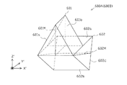
第1の平面に沿った断面形状が三角形状となる三角柱形状をなし、該第1の平面と直交する方向に沿った3つの面のうちの第1面と第2面との交線を通り第3面と直交する平面に沿って第1分岐手段(第1のハーフミラー)を有する第1の光学部材(第1のケスタープリズム)と、
前記第1の平面と直交する第2の平面に沿った断面形状が三角形状となる三角柱形状をなし、該第2の平面と直交する方向に沿った3つの面のうちの第1面と第2面との交線を通り第3面と直交する平面に沿って第2分岐手段(第2のハーフミラー)を有する第2の光学部材(第2のケスタープリズム)とを備え、
前記第1の光学部材の第3面と前記第2の光学部材の第1面とを相対向するように配置することにより、
前記第1の光学部材の前記第1面に対し(垂直に)入射される光を前記第1分岐手段にて2方向に分岐させ、このうち前記第1分岐手段にて反射した分割光を前記第1面にて前記第3面側に向け反射させ、前記第1分岐手段を透過した分割光を前記第2面にて前記第3面側に向け反射させることにより、前記第3面から平行する2つの分割光として出射させ、
前記第1の光学部材の第3面から出射された2つの分割光を前記第2の光学部材の第1面に対し(垂直に)入射させ、該2つの分割光をそれぞれ前記第2分岐手段にて2方向に分岐させ、このうち前記第2分岐手段にて反射した2つの分割光をそれぞれ前記第1面にて前記第3面側に向け反射させ、前記第2分岐手段を透過した2つの分割光をそれぞれ前記第2面にて前記第3面側に向け反射させることにより、前記第3面から平行する4つの分割光として出射させることを特徴とする手段10に記載の三次元計測装置。
Means 11. The spectroscopic means (first spectroscopic means and second spectroscopic means)
The cross-sectional shape along the first plane is a triangular prism shape having a triangular shape, and passes through the intersection of the first surface and the second surface among the three surfaces along the direction orthogonal to the first plane. A first optical member (first Kester prism) having first branching means (first half mirror) along a plane orthogonal to the third surface;
A cross-sectional shape along a second plane perpendicular to the first plane forms a triangular prism shape having a triangular shape, and the first surface of the three surfaces along the direction orthogonal to the second plane and the first surface A second optical member (second Kester prism) having a second branching means (second half mirror) along a plane passing through the intersection line with the second surface and orthogonal to the third surface;
By disposing the third surface of the first optical member and the first surface of the second optical member so as to face each other,
The light incident (perpendicularly) on the first surface of the first optical member is branched in two directions by the first branching means, and the divided light reflected by the first branching means is The first surface is reflected toward the third surface side, and the split light transmitted through the first branching means is reflected toward the third surface side at the second surface, thereby being parallel from the third surface. To be emitted as two split lights,
Two split lights emitted from the third surface of the first optical member are incident (perpendicularly) on the first surface of the second optical member, and the two split lights are respectively supplied to the second branch means. The two split lights reflected by the second branching unit are reflected by the first surface toward the third surface side and transmitted through the second branching unit. The three-dimensional measurement according to claim 10, wherein the two divided lights are respectively reflected by the second surface toward the third surface side, and are emitted as four divided lights in parallel from the third surface. apparatus.
上記手段11によれば、所定の光学系(干渉光学系)から出射される光を2行2列のマトリクス状に並ぶ4つの光に分光することができる。これにより、例えば下記の手段12のように複数の分割光を単一の撮像素子により同時撮像する構成において、撮像素子の撮像領域をマトリクス状に4等分した分割領域を、4つの分割光にそれぞれ割り当てることができるため、撮像素子の撮像領域を有効活用することができる。例えばアスペクト比が4:3の一般的な撮像素子の撮像領域を4等分した場合、各分割領域のアスペクト比は同じく4:3となるため、各分割領域内のより広範囲を利用可能となる。ひいては、さらなる計測精度の向上を図ることができる。 According to the means 11, the light emitted from the predetermined optical system (interference optical system) can be split into four lights arranged in a matrix of 2 rows and 2 columns. Thereby, for example, in a configuration in which a plurality of divided lights are simultaneously imaged by a single imaging element as in the following means 12, a divided area obtained by dividing the imaging area of the imaging element into four equal parts in a matrix is converted into four divided lights. Since each can be assigned, the imaging area of the imaging device can be used effectively. For example, when an imaging area of a general imaging device having an aspect ratio of 4: 3 is divided into four equal parts, the aspect ratio of each divided area is also 4: 3, so that a wider range within each divided area can be used. . As a result, the measurement accuracy can be further improved.
また、仮に回折格子を分光手段として用いた場合には分解能が低下するおそれがあるが、本手段では、1つの光を平行する2つの光に分割し、さらに該2つの光をそれぞれ平行する2つの光に分割することにより、平行する4つの光に分光する構成となっているため、分解能の低下抑制を図ることができる。 Further, if the diffraction grating is used as a spectroscopic means, the resolution may be lowered. However, in this means, one light is divided into two parallel lights, and each of the two lights is parallel. By dividing the light into four lights, the light is split into four parallel lights, so that a reduction in resolution can be suppressed.
さらに、1つの光を平行する2つの光に分割する手段として、上記構成を有する光学部材(ケスタープリズム)を採用しているため、分割された2つの光の光路長が光学的に等しくなる。結果として、分割された2つの光の光路長を調整する光路調整手段を備える必要がなく、部品点数の削減を図ると共に、構成の簡素化や装置の小型化等を図ることができる。 Furthermore, since the optical member (Kester prism) having the above-described configuration is employed as means for dividing one light into two parallel lights, the optical path lengths of the two divided lights are optically equal. As a result, it is not necessary to provide an optical path adjusting means for adjusting the optical path lengths of the two divided lights, and the number of parts can be reduced, and the configuration can be simplified and the apparatus can be downsized.
また、第1の光学部材の第3面と第2の光学部材の第1面とが当接していれば、分光手段に対し1つの光が入射されてから、4つの光が出射されるまでの間、光が光学部材内のみを進み、空気中に出ない構成となるため、空気の揺らぎ等による影響を低減することができる。 If the third surface of the first optical member and the first surface of the second optical member are in contact, one light is incident on the spectroscopic means until four lights are emitted. During this time, the light travels only in the optical member and does not exit into the air, so that the influence of air fluctuations can be reduced.
手段12.前記第1撮像手段は、少なくとも前記第1のフィルタ手段を透過する前記複数の分割光を同時に撮像可能な単一の撮像素子を備え、
前記第2撮像手段は、少なくとも前記第2のフィルタ手段を透過する前記複数の分割光を同時に撮像可能な単一の撮像素子を備えていることを特徴とする手段10又は11に記載の三次元計測装置。
Means 12. The first imaging means includes a single imaging element capable of simultaneously imaging the plurality of divided lights that pass through at least the first filter means,
The three-dimensional image according to means 10 or 11, wherein the second image pickup means comprises a single image pickup device capable of simultaneously picking up the plurality of divided lights that pass through at least the second filter means. Measuring device.
尚、複数の分割光を同時に撮像する場合には、撮像手段を構成する複数のカメラ(撮像素子)により各分割光をそれぞれ撮像する構成も考えられるが、かかる構成では、各カメラ(撮像素子)の違い等により、計測誤差が生じるおそれがある。 In the case where a plurality of divided lights are simultaneously imaged, a configuration in which each divided light is imaged by a plurality of cameras (imaging elements) constituting an imaging unit is also conceivable. In such a configuration, each camera (imaging element) There may be a measurement error due to the difference between the two.
この点、本手段によれば、複数の分割光を単一の撮像素子により同時撮像する構成となっているため、計測誤差等の発生を抑制し、計測精度の向上を図ることができる。 In this regard, according to the present means, since a plurality of divided lights are simultaneously imaged by a single image sensor, it is possible to suppress the occurrence of measurement errors and improve the measurement accuracy.
手段13.前記被計測物が、プリント基板に印刷されたクリーム半田、又は、ウエハ基板に形成された半田バンプであることを特徴とする手段1乃至12のいずれかに記載の三次元計測装置。
Means 13. The three-dimensional measuring apparatus according to any one of
上記手段13によれば、プリント基板に印刷されたクリーム半田、又は、ウエハ基板に形成された半田バンプの高さ計測等を行うことができる。ひいては、クリーム半田又は半田バンプの検査において、その計測値に基づいてクリーム半田又は半田バンプの良否判定を行うことができる。従って、かかる検査において、上記各手段の作用効果が奏されることとなり、精度よく良否判定を行うことができる。結果として、半田印刷検査装置又は半田バンプ検査装置における検査精度の向上を図ることができる。 According to the means 13, the height of the cream solder printed on the printed circuit board or the solder bump formed on the wafer substrate can be measured. As a result, in the inspection of cream solder or solder bumps, the quality of cream solder or solder bumps can be determined based on the measured values. Therefore, in such an inspection, the effect of each means described above is exhibited, and the quality determination can be performed with high accuracy. As a result, it is possible to improve the inspection accuracy in the solder printing inspection apparatus or the solder bump inspection apparatus.
〔第1実施形態〕
以下、三次元計測装置の一実施形態について図面を参照しつつ説明する。図1は本実施形態に係る三次元計測装置1の概略構成を示す模式図であり、図2は三次元計測装置1の電気的構成を示すブロック図である。以下、便宜上、図1の紙面前後方向を「X軸方向」とし、紙面上下方向を「Y軸方向」とし、紙面左右方向を「Z軸方向」として説明する。
[First Embodiment]
Hereinafter, an embodiment of a three-dimensional measurement apparatus will be described with reference to the drawings. FIG. 1 is a schematic diagram illustrating a schematic configuration of a three-
三次元計測装置1は、マイケルソン干渉計の原理に基づき構成されたものであり、特定波長の光を出力可能な2つの投光系2A,2B(第1投光系2A,第2投光系2B)と、該投光系2A,2Bからそれぞれ出射される光が入射される干渉光学系3と、該干渉光学系3から出射される光を撮像可能な2つの撮像系4A,4B(第1撮像系4A,第2撮像系4B)と、投光系2A,2Bや干渉光学系3、撮像系4A,4Bなどに係る各種制御や画像処理、演算処理等を行う制御装置5とを備えている。
The three-
ここで、「制御装置5」が本実施形態における「画像処理手段」を構成し、「干渉光学系3」が本実施形態における「所定の光学系(特定光学系)」を構成する。尚、本願に係る各実施形態においては、光の干渉を生じさせること(干渉縞画像を撮像すること)を目的として、入射する所定の光を2つの光(計測光及び参照光)に分割し、該2つの光に光路差を生じさせた上で、再度合成して出力する光学系を「干渉光学系」という。つまり、2つの光を内部で干渉させた上で干渉光として出力する光学系のみならず、2つの光を内部で干渉させることなく、単に合成光として出力する光学系についても「干渉光学系」と称している。従って、本実施形態にて後述するように、「干渉光学系」から、2つの光(計測光及び参照光)が干渉することなく合成光として出力される場合には、少なくとも撮像される前段階(例えば撮像系の内部など)において、所定の干渉手段を介して干渉光に変換することとなる。
Here, “
まず、2つの投光系2A,2B(第1投光系2A,第2投光系2B)の構成について詳しく説明する。第1投光系2Aは、第1発光部11A、第1光アイソレータ12A、第1無偏光ビームスプリッタ13Aなどを備えている。ここで「第1発光部11A」が本実施形態における「第1照射手段」を構成する。
First, the configuration of the two light projecting
図示は省略するが、第1発光部11Aは、特定波長λ1の直線偏光を出力可能なレーザ光源や、該レーザ光源から出力される直線偏光を拡大し平行光として出射するビームエキスパンダ、強度調整を行うための偏光板、偏光方向を調整するための1/2波長板などを備えている。
Although not shown, the first
かかる構成の下、本実施形態では、第1発光部11Aから、X軸方向及びY軸方向に対し45°傾斜した方向を偏光方向とする波長λ1(例えばλ1=1500nm)の直線偏光がZ軸方向左向きに出射される。ここで「波長λ1」が本実施形態における「第1波長」に相当する。以降、第1発光部11Aから出射される波長λ1の光を「第1光」という。
Under this configuration, in the present embodiment, linearly polarized light having a wavelength λ 1 (for example, λ 1 = 1500 nm) having a polarization direction in a direction inclined by 45 ° with respect to the X-axis direction and the Y-axis direction is emitted from the first
第1光アイソレータ12Aは、一方向(本実施形態ではZ軸方向左向き)に進む光のみを透過し逆方向(本実施形態ではZ軸方向右向き)の光を遮断する光学素子である。これにより、第1発光部11Aから出射された第1光のみを透過することとなり、戻り光による第1発光部11Aの損傷や不安定化などを防止することができる。
The first
第1無偏光ビームスプリッタ13Aは、直角プリズム(直角二等辺三角形を底面とする三角柱状のプリズム。以下同様。)を貼り合せて一体としたキューブ型の公知の光学部材であって、その接合面13Ahには例えば金属膜などのコーティングが施されている。「第1無偏光ビームスプリッタ13A」が本実施形態における「第1導光手段」を構成する。
The first
以下同様であるが、無偏光ビームスプリッタは、偏光状態も含め、入射光を所定の比率で透過光と反射光とに分割するものである。本実施形態では、1:1の分割比を持った所謂ハーフミラーを採用している。つまり、透過光のP偏光成分及びS偏光成分、並びに、反射光のP偏光成分及びS偏光成分が全て同じ比率で分割されると共に、透過光と反射光の各偏光状態は入射光の偏光状態と同じとなる。 The same applies hereinafter, but the non-polarizing beam splitter divides incident light into transmitted light and reflected light at a predetermined ratio including the polarization state. In the present embodiment, a so-called half mirror having a division ratio of 1: 1 is employed. That is, the P-polarized component and S-polarized component of the transmitted light, and the P-polarized component and S-polarized component of the reflected light are all divided at the same ratio, and the polarization states of the transmitted light and reflected light are the polarization states of the incident light. Will be the same.
尚、本実施形態では、図1の紙面に平行な方向(Y軸方向又はZ軸方向)を偏光方向とする直線偏光をP偏光(P偏光成分)といい、図1の紙面に垂直なX軸方向を偏光方向とする直線偏光をS偏光(S偏光成分)という。「P偏光」が「第1の偏光方向を有する第1偏光」に相当し、「S偏光」が「第2の偏光方向を有する第2偏光」に相当する。 In this embodiment, linearly polarized light having a polarization direction in a direction parallel to the paper surface of FIG. 1 (Y-axis direction or Z-axis direction) is called P-polarized light (P-polarized light component), and X perpendicular to the paper surface of FIG. Linearly polarized light whose axial direction is the polarization direction is called S-polarized light (S-polarized light component). “P-polarized light” corresponds to “first polarized light having a first polarization direction”, and “S-polarized light” corresponds to “second polarized light having a second polarization direction”.
また、第1無偏光ビームスプリッタ13Aは、その接合面13Ahを挟んで隣り合う2面のうちの一方がY軸方向と直交しかつ他方がZ軸方向と直交するように配置されている。つまり、第1無偏光ビームスプリッタ13Aの接合面13AhがY軸方向及びZ軸方向に対し45°傾斜するように配置されている。より詳しくは、第1光アイソレータ12Aを介して、第1発光部11AからZ軸方向左向きに入射する第1光の一部(半分)をZ軸方向左向きに透過させ、残り(半分)をY軸方向下向きに反射させるように配置されている。
Further, the first
第2投光系2Bは、上記第1投光系2Aと同様、第2発光部11B、第2光アイソレータ12B、第2無偏光ビームスプリッタ13Bなどを備えている。ここで「第2発光部11B」が本実施形態における「第2照射手段」を構成する。
Similar to the first
第2発光部11Bは、上記第1発光部11Aと同様、特定波長λ2の直線偏光を出力可能なレーザ光源や、該レーザ光源から出力される直線偏光を拡大し平行光として出射するビームエキスパンダ、強度調整を行うための偏光板、偏光方向を調整するための1/2波長板などを備えている。
Similarly to the first
かかる構成の下、本実施形態では、第2発光部11Bから、X軸方向及びZ軸方向に対し45°傾斜した方向を偏光方向とする波長λ2(例えばλ2=1503nm)の直線偏光がY軸方向上向きに出射される。ここで「波長λ2」が本実施形態における「第2波長」に相当する。以降、第2発光部11Bから出射される波長λ2の光を「第2光」という。
Under this configuration, in the present embodiment, linearly polarized light having a wavelength λ 2 (for example, λ 2 = 1503 nm) having a polarization direction in a direction inclined by 45 ° with respect to the X-axis direction and the Z-axis direction is emitted from the second
第2光アイソレータ12Bは、第1光アイソレータ12Aと同様、一方向(本実施形態ではY軸方向上向き)に進む光のみを透過し逆方向(本実施形態ではY軸方向下向き)の光を遮断する光学素子である。これにより、第2発光部11Bから出射された第2光のみを透過することとなり、戻り光による第2発光部11Bの損傷や不安定化などを防止することができる。
Similar to the first
第2無偏光ビームスプリッタ13Bは、第1無偏光ビームスプリッタ13Aと同様、直角プリズムを貼り合せて一体としたキューブ型の公知の光学部材であって、その接合面13Bhには例えば金属膜などのコーティングが施されている。「第2無偏光ビームスプリッタ13B」が本実施形態における「第2導光手段」を構成する。
Similar to the first
また、第2無偏光ビームスプリッタ13Bは、その接合面13Bhを挟んで隣り合う2面のうちの一方がY軸方向と直交しかつ他方がZ軸方向と直交するように配置されている。つまり、第2無偏光ビームスプリッタ13Bの接合面13BhがY軸方向及びZ軸方向に対し45°傾斜するように配置されている。より詳しくは、第2光アイソレータ12Bを介して、第2発光部11BからY軸方向上向きに入射する第2光の一部(半分)をY軸方向上向きに透過させ、残り(半分)をZ軸方向右向きに反射させるように配置されている。
The second
次に干渉光学系3の構成について詳しく説明する。干渉光学系3は、偏光ビームスプリッタ(PBS)20、1/4波長板21,22、参照面23、設置部24などを備えている。
Next, the configuration of the interference
偏光ビームスプリッタ20は、直角プリズムを貼り合せて一体としたキューブ型の公知の光学部材であって、その接合面(境界面)20hには例えば誘電体多層膜などのコーティングが施されている。
The
偏光ビームスプリッタ20は、入射される直線偏光を偏光方向が互いに直交する2つの偏光成分(P偏光成分とS偏光成分)に分割するものである。本実施形態における偏光ビームスプリッタ20は、P偏光成分を透過させ、S偏光成分を反射する構成となっている。また、本実施形態における偏光ビームスプリッタ20は、入射する所定の光を2つの光に分割する「分割手段」を構成すると共に、これらを再び合成する「合成手段」を構成することとなる。
The
偏光ビームスプリッタ20は、その接合面20hを挟んで隣り合う2面のうちの一方がY軸方向と直交しかつ他方がZ軸方向と直交するように配置されている。つまり、偏光ビームスプリッタ20の接合面20hがY軸方向及びZ軸方向に対し45°傾斜するように配置されている。
The
より詳しくは、上記第1無偏光ビームスプリッタ13AからY軸方向下向きに反射した第1光が入射する偏光ビームスプリッタ20の第1面(Y軸方向上側面)20a、並びに、該第1面20aと相対向する第3面(Y軸方向下側面)20cがY軸方向と直交するように配置されている。「偏光ビームスプリッタ20の第1面20a」が本実施形態における「第1入出力部」に相当する。
More specifically, the
一方、第1面20aと接合面20hを挟んで隣り合う面であって、上記第2無偏光ビームスプリッタ13BからZ軸方向右向きに反射した第2光が入射する偏光ビームスプリッタ20の第2面(Z軸方向左側面)20b、並びに、該第2面20bと相対向する第4面(Z軸方向右側面)20dがZ軸方向と直交するように配置されている。「偏光ビームスプリッタ20の第2面20b」が本実施形態における「第2入出力部」に相当する。
On the other hand, the second surface of the
また、偏光ビームスプリッタ20の第3面20cとY軸方向に相対向するように1/4波長板21が配置され、該1/4波長板21とY軸方向に相対向するように参照面23が配置されている。
A quarter-
1/4波長板21は、本実施形態における「第1の1/4波長板」に相当するものであり、直線偏光を円偏光に変換しかつ円偏光を直線偏光に変換する機能を有する。つまり、偏光ビームスプリッタ20の第3面20cから出射される直線偏光(参照光)は1/4波長板21を介して円偏光に変換された上で参照面23に対し照射される。また、参照面23で反射した参照光は、再度、1/4波長板21を介して円偏光から直線偏光に変換された上で偏光ビームスプリッタ20の第3面20cに入射する。
The
一方、偏光ビームスプリッタ20の第4面20dとZ軸方向に相対向するように1/4波長板22が配置され、該1/4波長板22とZ軸方向に相対向するように設置部24が配置されている。
On the other hand, a quarter-
1/4波長板22は、本実施形態における「第2の1/4波長板」に相当するものであり、直線偏光を円偏光に変換しかつ円偏光を直線偏光に変換する機能を有する。つまり、偏光ビームスプリッタ20の第4面20dから出射される直線偏光(計測光)は1/4波長板22を介して円偏光に変換された上で設置部24に置かれた被計測物としてのワークWに対し照射される。また、ワークWにて反射した計測光は、再度、1/4波長板22を介して円偏光から直線偏光に変換された上で偏光ビームスプリッタ20の第4面20dに入射する。
The
次に2つの撮像系4A,4B(第1撮像系4A,第2撮像系4B)の構成について詳しく説明する。第1撮像系4Aは、1/4波長板31A、第1偏光板32A、第1撮像手段を構成する第1カメラ33Aなどを備えている。
Next, the configuration of the two
1/4波長板31Aは、第2無偏光ビームスプリッタ13BをZ軸方向左向きに透過してきた直線偏光(第1光の参照光成分及び計測光成分)をそれぞれ円偏光に変換するためのものである。
The quarter-
第1偏光板32Aは、1/4波長板31Aにより円偏光に変換された第1光の各成分を選択的に透過させるものである。これにより、回転方向の異なる第1光の参照光成分と計測光成分とを特定の位相について干渉させることができる。「第1偏光板32A」が本実施形態における「第1位相シフト手段」及び「干渉手段」を構成する。
The first
本実施形態に係る第1偏光板32Aは、Z軸方向を軸心として回転可能に構成されると共に、その透過軸方向が45°ずつ変化するように制御される。具体的には、透過軸方向がY軸方向に対し「0°」、「45°」、「90°」、「135°」となるように変化する。
The first
これにより、第1偏光板32Aを透過する第1光の参照光成分及び計測光成分を4通りの位相で干渉させることができる。つまり、位相が90°ずつ異なる干渉光を生成することができる。具体的には、位相が「0°」の干渉光、位相が「90°」の干渉光、位相が「180°」の干渉光、位相が「270°」の干渉光を生成することができる。
Thereby, the reference light component and measurement light component of the 1st light which permeate | transmit the 1st
第1カメラ33Aは、レンズや撮像素子等を備えてなる公知のものである。本実施形態では、第1カメラ33Aの撮像素子として、CCDエリアセンサを採用している。勿論、撮像素子は、これに限定されるものではなく、例えばCMOSエリアセンサ等を採用してもよい。
The
第1カメラ33Aによって撮像された画像データは、第1カメラ33A内部においてデジタル信号に変換された上で、デジタル信号の形で制御装置5(画像データ記憶装置54)に入力されるようになっている。
Image data captured by the
具体的には、第1光に係る位相「0°」の干渉縞画像、位相「90°」の干渉縞画像、位相「180°」の干渉縞画像、位相「270°」の干渉縞画像が第1カメラ33Aにより撮像されることとなる。
Specifically, an interference fringe image having a phase “0 °”, an interference fringe image having a phase “90 °”, an interference fringe image having a phase “180 °”, and an interference fringe image having a phase “270 °” are associated with the first light. The image is picked up by the
第2撮像系4Bは、第1撮像系4Aと同様、1/4波長板31B、第2偏光板32B、第2撮像手段を構成する第2カメラ33Bなどを備えている。
Similar to the
1/4波長板31Bは、第1無偏光ビームスプリッタ13AをY軸方向上向きに透過してきた直線偏光(第2光の参照光成分及び計測光成分)をそれぞれ円偏光に変換するためのものである。
The
第2偏光板32Bは、第1偏光板32Aと同様、1/4波長板31Bにより円偏光に変換された第2光の各成分を選択的に透過させるものである。これにより、回転方向の異なる第2光の参照光成分と計測光成分とを特定の位相について干渉させることができる。「第2偏光板32B」が本実施形態における「第2位相シフト手段」及び「干渉手段」を構成する。
Similar to the first
本実施形態に係る第2偏光板32Bは、Y軸方向を軸心として回転可能に構成されると共に、その透過軸方向が45°ずつ変化するように制御される。具体的には、透過軸方向がX軸方向に対し「0°」、「45°」、「90°」、「135°」となるように変化する。
The second
これにより、第2偏光板32Bを透過する第2光の参照光成分及び計測光成分を4通りの位相で干渉させることができる。つまり、位相が90°ずつ異なる干渉光を生成することができる。具体的には、位相が「0°」の干渉光、位相が「90°」の干渉光、位相が「180°」の干渉光、位相が「270°」の干渉光を生成することができる。
Thereby, the reference light component and measurement light component of the 2nd light which permeate | transmit the 2nd
第2カメラ33Bは、第1カメラ33Aと同様、レンズや撮像素子等を備えてなる公知のものである。本実施形態では、第1カメラ33Aと同様、第2カメラ33Bの撮像素子として、CCDエリアセンサを採用している。勿論、撮像素子は、これに限定されるものではなく、例えばCMOSエリアセンサ等を採用してもよい。
Similar to the
第1カメラ33Aと同様、第2カメラ33Bによって撮像された画像データは、第2カメラ33B内部においてデジタル信号に変換された上で、デジタル信号の形で制御装置5(画像データ記憶装置54)に入力されるようになっている。
Similar to the
具体的には、第2光に係る位相「0°」の干渉縞画像、位相「90°」の干渉縞画像、位相「180°」の干渉縞画像、位相「270°」の干渉縞画像が第2カメラ33Bにより撮像されることとなる。
Specifically, an interference fringe image having a phase “0 °”, an interference fringe image having a phase “90 °”, an interference fringe image having a phase “180 °”, and an interference fringe image having a phase “270 °” related to the second light. The image is taken by the
ここで制御装置5の電気的構成について説明する。図2に示すように、制御装置5は、三次元計測装置1全体の制御を司るCPU及び入出力インターフェース51、キーボードやマウス、あるいは、タッチパネルで構成される「入力手段」としての入力装置52、液晶画面などの表示画面を有する「表示手段」としての表示装置53、カメラ33A,33Bにより撮像された画像データ等を順次記憶するための画像データ記憶装置54、各種演算結果を記憶するための演算結果記憶装置55、各種情報を予め記憶しておく設定データ記憶装置56を備えている。なお、これら各装置52〜56は、CPU及び入出力インターフェース51に対し電気的に接続されている。
Here, the electrical configuration of the
次に三次元計測装置1の作用について説明する。尚、後述するように、本実施形態における第1光及び第2光の照射は同時に行われるものであり、第1光の光路と第2光の光路が一部で重なることとなるが、ここでは、より分かりやすくするため、第1光及び第2光の光路ごとに異なる図面を用いて個別に説明する。
Next, the operation of the three-
まず第1光の光路について図3を参照して説明する。図3に示すように、波長λ1の第1光(偏光方向がX軸方向及びY軸方向に対し45°傾斜した直線偏光)が第1発光部11AからZ軸方向左向きに出射される。
First, the optical path of the first light will be described with reference to FIG. As shown in FIG. 3, the first light of wavelength λ 1 (linearly polarized light whose polarization direction is inclined by 45 ° with respect to the X-axis direction and the Y-axis direction) is emitted leftward in the Z-axis direction from the first
第1発光部11Aから出射された第1光は、第1光アイソレータ12Aを通過し、第1無偏光ビームスプリッタ13Aに入射する。第1無偏光ビームスプリッタ13Aに入射した第1光の一部はZ軸方向左向きに透過し、残りはY軸方向下向きに反射する。
The first light emitted from the first
このうち、Y軸方向下向きに反射した第1光(偏光方向がX軸方向及びZ軸方向に対し45°傾斜した直線偏光)は、偏光ビームスプリッタ20の第1面20aに入射する。一方、Z軸方向左向きに透過した第1光は、何らかの光学系等に入射することなく、捨て光となる。
Among these, the first light reflected downward in the Y-axis direction (linearly polarized light whose polarization direction is inclined by 45 ° with respect to the X-axis direction and the Z-axis direction) is incident on the
ここで、捨て光となる光を、必要に応じて波長計測あるいは光のパワー計測に利用すれば、光源を安定化させ如いては計測精度の向上を図ることができる(以下同様)。 Here, if the discarded light is used for wavelength measurement or light power measurement as required, the measurement accuracy can be improved by stabilizing the light source (the same applies hereinafter).
偏光ビームスプリッタ20の第1面20aからY軸方向下向きに入射した第1光は、そのP偏光成分がY軸方向下向きに透過して第3面20cから参照光として出射される一方、そのS偏光成分がZ軸方向右向きに反射して第4面20dから計測光として出射される。
The first light incident downward from the
偏光ビームスプリッタ20の第3面20cから出射した第1光に係る参照光(P偏光)は、1/4波長板21を通過することにより右回りの円偏光に変換された後、参照面23で反射する。ここで、光の進行方向に対する回転方向は維持される。その後、第1光に係る参照光は、再度、1/4波長板21を通過することで、右回りの円偏光からS偏光に変換された上で偏光ビームスプリッタ20の第3面20cに再入射する。
The reference light (P-polarized light) related to the first light emitted from the
一方、偏光ビームスプリッタ20の第4面20dから出射した第1光に係る計測光(S偏光)は、1/4波長板22を通過することにより左回りの円偏光に変換された後、ワークWで反射する。ここで、光の進行方向に対する回転方向は維持される。その後、第1光に係る計測光は、再度、1/4波長板22を通過することで、左回りの円偏光からP偏光に変換された上で偏光ビームスプリッタ20の第4面20dに再入射する。
On the other hand, the measurement light (S-polarized light) related to the first light emitted from the
ここで、偏光ビームスプリッタ20の第3面20cから再入射した第1光に係る参照光(S偏光)が接合面20hにてZ軸方向左向きに反射する一方、第4面20dから再入射した第1光に係る計測光(P偏光)は接合面20hをZ軸方向左向きに透過する。そして、第1光に係る参照光及び計測光が合成された状態の合成光が出力光として偏光ビームスプリッタ20の第2面20bから出射される。
Here, the reference light (S-polarized light) related to the first light re-entered from the
偏光ビームスプリッタ20の第2面20bから出射された第1光に係る合成光(参照光及び計測光)は、第2無偏光ビームスプリッタ13Bに入射する。第2無偏光ビームスプリッタ13Bに対しZ軸方向左向きに入射した第1光に係る合成光は、その一部がZ軸方向左向きに透過し、残りがY軸方向下向きに反射する。このうち、Z軸方向左向きに透過した合成光(参照光及び計測光)は第1撮像系4Aに入射することとなる。一方、Y軸方向下向きに反射した合成光は、第2光アイソレータ12Bによりその進行を遮断され、捨て光となる。
The combined light (reference light and measurement light) related to the first light emitted from the
第1撮像系4Aに入射した第1光に係る合成光(参照光及び計測光)は、まず1/4波長板31Aにより、その参照光成分(S偏光成分)が左回りの円偏光に変換され、その計測光成分(P偏光成分)が右回りの円偏光に変換される。ここで、左回りの円偏光と右回りの円偏光は回転方向が異なるので干渉しない。
The combined light (reference light and measurement light) related to the first light incident on the
第1光に係る合成光は、続いて第1偏光板32Aを通過することにより、その参照光成分と計測光成分とが第1偏光板32Aの角度に応じた位相で干渉する。そして、かかる第1光に係る干渉光が第1カメラ33Aにより撮像される。
The synthesized light related to the first light subsequently passes through the first
次に第2光の光路について図4を参照して説明する。図4に示すように、波長λ2の第2光(偏光方向がX軸方向及びZ軸方向に対し45°傾斜した直線偏光)が第2発光部11BからY軸方向上向きに出射される。
Next, the optical path of the second light will be described with reference to FIG. As shown in FIG. 4, the second light having the wavelength λ 2 (linearly polarized light whose polarization direction is inclined by 45 ° with respect to the X-axis direction and the Z-axis direction) is emitted upward from the second
第2発光部11Bから出射された第2光は、第2光アイソレータ12Bを通過し、第2無偏光ビームスプリッタ13Bに入射する。第2無偏光ビームスプリッタ13Bに入射した第2光の一部はY軸方向上向きに透過し、残りはZ軸方向右向きに反射する。
The second light emitted from the second
このうち、Z軸方向右向きに反射した第2光(偏光方向がX軸方向及びY軸方向に対し45°傾斜した直線偏光)は、偏光ビームスプリッタ20の第2面20bに入射する。一方、Y軸方向上向きに透過した第2光は、何らかの光学系等に入射することなく、捨て光となる。
Among these, the second light reflected to the right in the Z-axis direction (linearly polarized light whose polarization direction is inclined by 45 ° with respect to the X-axis direction and the Y-axis direction) is incident on the
偏光ビームスプリッタ20の第2面20bからZ軸方向右向きに入射した第2光は、そのS偏光成分がY軸方向下向きに反射して第3面20cから参照光として出射される一方、そのP偏光成分がZ軸方向右向きに透過して第4面20dから計測光として出射される。
The second light incident rightward in the Z-axis direction from the
偏光ビームスプリッタ20の第3面20cから出射した第2光に係る参照光(S偏光)は、1/4波長板21を通過することにより左回りの円偏光に変換された後、参照面23で反射する。ここで、光の進行方向に対する回転方向は維持される。その後、第2光に係る参照光は、再度、1/4波長板21を通過することで、左回りの円偏光からP偏光に変換された上で偏光ビームスプリッタ20の第3面20cに再入射する。
The reference light (S-polarized light) related to the second light emitted from the
一方、偏光ビームスプリッタ20の第4面20dから出射した第2光に係る計測光(P偏光)は、1/4波長板22を通過することにより右回りの円偏光に変換された後、ワークWで反射する。ここで、光の進行方向に対する回転方向は維持される。その後、第2光に係る計測光は、再度、1/4波長板22を通過することで、右回りの円偏光からS偏光に変換された上で偏光ビームスプリッタ20の第4面20dに再入射する。
On the other hand, the measurement light (P-polarized light) related to the second light emitted from the
ここで、偏光ビームスプリッタ20の第3面20cから再入射した第2光に係る参照光(P偏光)は接合面20hをY軸方向上向きに透過する一方、第4面20dから再入射した第2光に係る計測光(S偏光)は接合面20hにてY軸方向上向きに反射する。そして、第2光に係る参照光及び計測光が合成された状態の合成光が出力光として偏光ビームスプリッタ20の第1面20aから出射される。
Here, the reference light (P-polarized light) related to the second light re-entered from the
偏光ビームスプリッタ20の第1面20aから出射された第2光に係る合成光(参照光及び計測光)は、第1無偏光ビームスプリッタ13Aに入射する。第1無偏光ビームスプリッタ13Aに対しY軸方向上向きに入射した第2光に係る合成光は、その一部がY軸方向上向きに透過し、残りがZ軸方向右向きに反射する。このうち、Y軸方向上向きに透過した合成光(参照光及び計測光)は第2撮像系4Bに入射することとなる。一方、Z軸方向右向きに反射した合成光は、第1光アイソレータ12Aによりその進行を遮断され、捨て光となる。
The combined light (reference light and measurement light) related to the second light emitted from the
第2撮像系4Bに入射した第2光に係る合成光(参照光及び計測光)は、まず1/4波長板31Bにより、その参照光成分(P偏光成分)が右回りの円偏光に変換され、その計測光成分(S偏光成分)が左回りの円偏光に変換される。ここで、左回りの円偏光と右回りの円偏光は回転方向が異なるので干渉しない。
The combined light (reference light and measurement light) related to the second light incident on the
第2光に係る合成光は、続いて第2偏光板32Bを通過することにより、その参照光成分と計測光成分とが第2偏光板32Bの角度に応じた位相で干渉する。そして、かかる第2光に係る干渉光が第2カメラ33Bにより撮像される。
The combined light related to the second light subsequently passes through the second
次に、制御装置5によって実行される形状計測処理の手順について詳しく説明する。まずは、設置部24へワークWを設置した後、第1撮像系4Aの第1偏光板32Aの透過軸方向を所定の基準位置(例えば「0°」)に設定すると共に、第2撮像系4Bの第2偏光板32Bの透過軸方向を所定の基準位置(例えば「0°」)に設定する。
Next, the procedure of the shape measurement process executed by the
続いて、第1投光系2Aから第1光を照射すると同時に、第2投光系2Bから第2光を照射する。その結果、干渉光学系3の偏光ビームスプリッタ20の第2面20bから第1光に係る合成光(参照光及び計測光)が出射されると同時に、偏光ビームスプリッタ20の第1面20aから第2光に係る合成光(参照光及び計測光)が出射される。
Subsequently, the first light is emitted from the first
そして、偏光ビームスプリッタ20の第2面20bから出射された第1光に係る合成光を第1撮像系4Aにより撮像すると同時に、偏光ビームスプリッタ20の第1面20aから出射された第2光に係る合成光を第2撮像系4Bにより撮像する。
The combined light related to the first light emitted from the
尚、ここでは第1偏光板32A及び第2偏光板32Bの透過軸方向がそれぞれ「0°」に設定されているため、第1カメラ33Aでは第1光に係る位相「0°」の干渉縞画像が撮像され、第2カメラ33Bでは第2光に係る位相「0°」の干渉縞画像が撮像されることとなる。
Here, since the transmission axis directions of the first
そして、各カメラ33A,33Bからそれぞれ撮像された画像データが制御装置5へ出力される。制御装置5は、入力した画像データを画像データ記憶装置54に記憶する。
Then, image data captured from each of the cameras 33 </ b> A and 33 </ b> B is output to the
次に制御装置5は、第1撮像系4Aの第1偏光板32A、及び、第2撮像系4Bの第2偏光板32Bの切替処理を行う。具体的には、第1偏光板32A及び第2偏光板32Bをそれぞれ透過軸方向が「45°」となる位置まで回動変位させる。
Next, the
該切替処理が終了すると、制御装置5は、上記一連の1回目の撮像処理と同様の2回目の撮像処理を行う。つまり、制御装置5は、第1投光系2Aから第1光を照射すると同時に、第2投光系2Bから第2光を照射し、偏光ビームスプリッタ20の第2面20bから出射された第1光に係る合成光を第1撮像系4Aにより撮像すると同時に、偏光ビームスプリッタ20の第1面20aから出射された第2光に係る合成光を第2撮像系4Bにより撮像する。これにより、第1光に係る位相「90°」の干渉縞画像が取得されると共に、第2光に係る位相「90°」の干渉縞画像が撮像されることとなる。
When the switching process ends, the
以降、上記1回目及び2回目の撮像処理と同様の撮像処理が2回繰り返し行われる。つまり、第1偏光板32A及び第2偏光板32Bの透過軸方向を「90°」に設定した状態で3回目の撮像処理を行い、第1光に係る位相「180°」の干渉縞画像を取得すると共に、第2光に係る位相「180°」の干渉縞画像を取得する。
Thereafter, the same imaging process as the first and second imaging processes is repeated twice. That is, the third imaging process is performed in a state where the transmission axis directions of the first
その後、第1偏光板32A及び第2偏光板32Bの透過軸方向を「135°」に設定した状態で4回目の撮像処理を行い、第1光に係る位相「270°」の干渉縞画像を取得すると共に、第2光に係る位相「270°」の干渉縞画像を取得する。
Thereafter, the fourth imaging process is performed in a state where the transmission axis directions of the first
このように、4回の撮像処理を行うことにより、三次元計測を行う上で必要な全ての画像データ(第1光に係る4通りの干渉縞画像データ、及び、第2光に係る4通りの干渉縞画像データからなる計8つの干渉縞画像データ)を取得することができる。 As described above, by performing the imaging process four times, all the image data necessary for performing the three-dimensional measurement (four kinds of interference fringe image data relating to the first light and four kinds relating to the second light). A total of eight interference fringe image data).
そして、制御装置5は、画像データ記憶装置54に記憶された第1光に係る4通りの干渉縞画像データ、及び、第2光に係る4通りの干渉縞画像データを基に、位相シフト法によりワークWの表面形状を計測する。つまり、ワークWの表面上の各位置における高さ情報を算出する。
Then, the
まずは一般的な位相シフト法による高さ計測の原理について説明する。第1光又は第2光に係る4通りの干渉縞画像データの同一座標位置(x,y)における干渉縞強度、すなわち輝度I1(x,y)、I2(x,y)、I3(x,y)、I4(x,y)は、下記[数1]の関係式で表すことができる。 First, the principle of height measurement by a general phase shift method will be described. Interference fringe intensity at the same coordinate position (x, y) of the four kinds of interference fringe image data relating to the first light or the second light, that is, luminances I 1 (x, y), I 2 (x, y), I 3 (X, y) and I 4 (x, y) can be expressed by the following relational expression [Formula 1].

ここで、Δφ(x,y)は、座標(x,y)における計測光と参照光との光路差に基づく位相差を表している。また、A(x,y)は干渉光の振幅、B(x,y)はバイアスを表している。但し、参照光は均一であるため、これを基準として見ると、Δφ(x,y)は「計測光の位相」を表し、A(x,y)は「計測光の振幅」を表すこととなる。 Here, Δφ (x, y) represents a phase difference based on the optical path difference between the measurement light and the reference light at the coordinates (x, y). A (x, y) represents the amplitude of the interference light, and B (x, y) represents the bias. However, since the reference light is uniform, Δφ (x, y) represents “the phase of the measurement light” and A (x, y) represents “the amplitude of the measurement light”. Become.
従って、計測光の位相Δφ(x,y)は、上記[数1]の関係式を基に、下記[数2]の関係式で求めることができる。 Therefore, the phase Δφ (x, y) of the measurement light can be obtained by the following relational expression [Formula 2] based on the relational expression [Formula 1].
また、計測光の振幅A(x,y)は、上記[数1]の関係式を基に、下記[数3]の関係式で求めることができる。 Further, the amplitude A (x, y) of the measurement light can be obtained from the following [Expression 3] based on the above [Expression 1] relational expression.
次に、上記位相Δφ(x,y)と振幅A(x,y)から、下記[数4]の関係式を基に撮像素子面上における複素振幅Eo(x,y)を算出する。ここで、iは虚数単位を表している。 Next, the complex amplitude Eo (x, y) on the image sensor surface is calculated from the phase Δφ (x, y) and the amplitude A (x, y) based on the following relational expression [4]. Here, i represents an imaginary unit.
続いて、複素振幅Eo(x,y)を基に、ワークW面上の座標(ξ,η)における複素振幅Eo(ξ,η)を算出する。 Subsequently, based on the complex amplitude Eo (x, y), the complex amplitude Eo (ξ, η) at the coordinates (ξ, η) on the workpiece W plane is calculated.
まずは、下記[数5]に示すように、上記複素振幅Eo(x,y)をフレネル変換する。ここで、λは波長を表す。 First, as shown in [Formula 5] below, the complex amplitude Eo (x, y) is subjected to Fresnel transformation. Here, λ represents a wavelength.
これをEo(ξ,η)について解くと、下記[数6]のようになる。 Solving this for Eo (ξ, η) yields [Equation 6] below.
さらに、得られた複素振幅Eo(ξ,η)から、下記[数7]の関係式を基に、計測光の位相φ(ξ,η)と、計測光の振幅A(ξ,η)を算出する。 Furthermore, from the obtained complex amplitude Eo (ξ, η), the phase φ (ξ, η) of the measurement light and the amplitude A (ξ, η) of the measurement light are calculated based on the relational expression [Formula 7] below. calculate.
計測光の位相φ(ξ,η)は、下記[数8]の関係式により求めることができる。 The phase φ (ξ, η) of the measurement light can be obtained by the following relational expression [Equation 8].
計測光の振幅A(ξ,η)は、下記[数9]の関係式により求めることができる。 The amplitude A (ξ, η) of the measurement light can be obtained by the following relational expression [Equation 9].
その後、位相−高さ変換処理を行い、ワークWの表面の凹凸形状を3次元的に示す高さ情報z(ξ,η)を算出する。 Thereafter, phase-height conversion processing is performed to calculate height information z (ξ, η) that three-dimensionally shows the uneven shape of the surface of the workpiece W.
高さ情報z(ξ,η)は、下記[数10]の関係式により算出することができる。 The height information z (ξ, η) can be calculated by the following relational expression [Equation 10].
次に2波長位相シフト法の原理について説明する。波長の異なる2種類の光を用いることで計測レンジを広げることができる。 Next, the principle of the two-wavelength phase shift method will be described. The measurement range can be expanded by using two types of light having different wavelengths.
波長の異なる2種類の光(波長λ1,λ2)を用いて計測を行った場合には、その合成波長λ0の光で計測を行ったことと同じこととなる。そして、その計測レンジはλ0/2に拡大することとなる。合成波長λ0は、下記式(M1)で表すことができる。 When measurement is performed using two types of light having different wavelengths (wavelengths λ 1 and λ 2 ), the measurement is the same as the measurement using light having the combined wavelength λ 0 . Then, the measurement range and thus to increase the lambda 0/2. The synthetic wavelength λ 0 can be expressed by the following formula (M1).
λ0=(λ1×λ2)/(λ2−λ1) ・・・(M1)
但し、λ2>λ1とする。
λ 0 = (λ 1 × λ 2 ) / (λ 2 −λ 1 ) (M1)
However, it is assumed that λ 2 > λ 1 .
ここで、例えばλ1=1500nm、λ2=1503nmとすると、上記式(M1)から、λ0=751.500μmとなり、計測レンジはλ0/2=375.750μmとなる。 For example, when λ 1 = 1500 nm and λ 2 = 1503 nm, from the above equation (M1), λ 0 = 751.500 μm and the measurement range is λ 0 /2=375.750 μm.
2波長位相シフト法を行う際には、まず波長λ1の第1光に係る4通りの干渉縞画像データの輝度I1(x,y)、I2(x,y)、I3(x,y)、I4(x,y)を基に(上記[数1]参照)、ワークW面上の座標(ξ,η)における第1光に係る計測光の位相φ1(ξ,η)を算出する(上記[数8]参照)。ここで求められる位相φ1(ξ,η)が本実施形態における「第1計測値」に相当し、これを算出する処理機能により「第1計測値取得手段」が構成される。 When performing the two-wavelength phase-shift method, first, the interference fringe image data of four types of the first optical wavelength lambda 1 luminance I 1 (x, y), I 2 (x, y), I 3 (x , Y), I 4 (x, y) (see [Expression 1] above), the phase φ 1 (ξ, η) of the measurement light related to the first light at the coordinates (ξ, η) on the workpiece W surface ) Is calculated (see [Equation 8] above). The phase φ 1 (ξ, η) obtained here corresponds to the “first measurement value” in the present embodiment, and the “first measurement value acquisition unit” is configured by a processing function for calculating this.
尚、第1光に係る計測の下、座標(ξ,η)における高さ情報z(ξ,η)は、下記式(M2)で表すことができる。 Note that the height information z (ξ, η) at the coordinates (ξ, η) under the measurement of the first light can be expressed by the following equation (M2).
z(ξ,η)=d1(ξ,η)/2
=[λ1×φ1(ξ,η)/4π]+[m1(ξ,η)×λ1/2] ・・・(M2)
但し、d1(ξ,η)は、第1光に係る計測光と参照光との光路差を表し、m1(ξ,η)は、第1光に係る縞次数を表す。
z (ξ, η) = d 1 (ξ, η) / 2
= [Λ 1 × φ 1 ( ξ, η) / 4π] + [m 1 (ξ, η) ×
Here, d 1 (ξ, η) represents an optical path difference between the measurement light related to the first light and the reference light, and m 1 (ξ, η) represents a fringe order related to the first light.
よって、位相φ1(ξ,η)は下記式(M2´)で表すことができる。 Therefore, the phase φ 1 (ξ, η) can be expressed by the following formula (M2 ′).
φ1(ξ,η)=(4π/λ1)×z(ξ,η)−2πm1(ξ,η) ・・・(M2´)
同様に、波長λ2の第2光に係る4通りの干渉縞画像データの輝度I1(x,y)、I2(x,y)、I3(x,y)、I4(x,y)を基に(上記[数1]参照)、ワークW面上の座標(ξ,η)における第2光に係る計測光の位相φ2(ξ,η)を算出する(上記[数8]参照)。ここで求められる位相φ2(ξ,η)が本実施形態における「第2計測値」に相当し、これを算出する処理機能により「第2計測値取得手段」が構成される。
φ 1 (ξ, η) = (4π / λ 1 ) × z (ξ, η) −2πm 1 (ξ, η) (M2 ′)
Similarly, the luminances I 1 (x, y), I 2 (x, y), I 3 (x, y), I 4 (x, y) of the four kinds of interference fringe image data relating to the second light of the wavelength λ 2 y) (see the above [Equation 1]), the phase φ 2 (ξ, η) of the measurement light related to the second light at the coordinates (ξ, η) on the workpiece W surface is calculated (the above [Equation 8] ]reference). The phase φ 2 (ξ, η) obtained here corresponds to the “second measurement value” in the present embodiment, and the “second measurement value acquisition unit” is configured by the processing function for calculating this.
尚、第2光に係る計測の下、座標(ξ,η)における高さ情報z(ξ,η)は、下記式(M3)で表すことができる。 Note that the height information z (ξ, η) at the coordinates (ξ, η) under measurement related to the second light can be expressed by the following equation (M3).
z(ξ,η)=d2(ξ,η)/2
=[λ2×φ2(ξ,η)/4π]+[m2(ξ,η)×λ2/2] ・・・(M3)
但し、d2(ξ,η)は、第2光に係る計測光と参照光との光路差を表し、m2(ξ,η)は、第2光に係る縞次数を表す。
z (ξ, η) = d 2 (ξ, η) / 2
= [Λ 2 × φ 2 ( ξ, η) / 4π] + [m 2 (ξ, η) × λ 2/2] ··· (M3)
Here, d 2 (ξ, η) represents the optical path difference between the measurement light related to the second light and the reference light, and m 2 (ξ, η) represents the fringe order related to the second light.
よって、位相φ2(ξ,η)は下記式(M3´)で表すことができる。 Therefore, the phase φ 2 (ξ, η) can be expressed by the following formula (M3 ′).
φ2(ξ,η)=(4π/λ2)×z(ξ,η)−2πm2(ξ,η) ・・・(M3´)
続いて、波長λ1の第1光に係る縞次数m1(ξ,η)、又は、波長λ2の第2光に係る縞次数m2(ξ,η)を決定する。縞次数m1,m2は、2種類の光(波長λ1,λ2)の光路差Δd及び波長差Δλを基に求めることができる。ここで光路差Δd及び波長差Δλは、それぞれ下記式(M4),(M5)のように表すことができる。
φ 2 (ξ, η) = (4π / λ 2 ) × z (ξ, η) −2πm 2 (ξ, η) (M3 ′)
Subsequently, the fringe order m 1 (ξ, η) related to the first light of wavelength λ 1 or the fringe order m 2 (ξ, η) related to the second light of wavelength λ 2 is determined. The fringe orders m 1 and m 2 can be obtained based on the optical path difference Δd and the wavelength difference Δλ of two types of light (wavelengths λ 1 and λ 2 ). Here, the optical path difference Δd and the wavelength difference Δλ can be expressed by the following equations (M4) and (M5), respectively.
Δd=(λ1×φ1−λ2×φ2)/2π ・・・(M4)
Δλ=λ2−λ1 ・・・(M5)
但し、λ2>λ1とする。
Δd = (λ 1 × φ 1 −λ 2 × φ 2 ) / 2π (M4)
Δλ = λ 2 −λ 1 (M5)
However, it is assumed that λ 2 > λ 1 .
尚、2波長の合成波長λ0の計測レンジ内において、縞次数m1,m2の関係は、以下の3つの場合に分けられ、各場合ごとに縞次数m1(ξ,η)、m2(ξ,η)を決定する計算式が異なる。ここで、例えば縞次数m1(ξ,η)を決定する場合について説明する。勿論、縞次数m2(ξ,η)についても、同様の手法により求めることができる。 In the measurement range of the two combined wavelengths λ 0 , the relationship between the fringe orders m 1 and m 2 is divided into the following three cases. For each case, the fringe orders m 1 (ξ, η), m 2 The formula for determining (ξ, η) is different. Here, for example, a case where the fringe order m 1 (ξ, η) is determined will be described. Of course, the fringe order m 2 (ξ, η) can also be obtained by the same method.
例えば「φ1−φ2<−π」の場合には「m1−m2=−1」となり、かかる場合、m1は下記式(M6)のように表すことができる。 For example, in the case of “φ 1 −φ 2 <−π”, “m 1 −m 2 = −1”. In such a case, m 1 can be expressed as the following formula (M6).
m1=(Δd/Δλ)−(λ2/Δλ)
=(λ1×φ1−λ2×φ2)/2π(λ2−λ1)−λ2/(λ2−λ1)・・・(M6)
「−π<φ1−φ2<π」の場合には「m1−m2=0」となり、かかる場合、m1は下記式(M7)のように表すことができる。
m 1 = (Δd / Δλ) − (λ 2 / Δλ)
= (Λ 1 × φ 1 −λ 2 × φ 2 ) / 2π (λ 2 −λ 1 ) −λ 2 / (λ 2 −λ 1 ) (M6)
In the case of “−π <φ 1 −φ 2 <π”, “m 1 −m 2 = 0”. In such a case, m 1 can be expressed as the following formula (M7).
m1=Δd/Δλ
=(λ1×φ1−λ2×φ2)/2π(λ2−λ1)・・・(M7)
「φ1−φ2>π」の場合には「m1−m2=+1」となり、かかる場合、m1は下記式(M8)のように表すことができる。
m 1 = Δd / Δλ
= (Λ 1 × φ 1 −λ 2 × φ 2 ) / 2π (λ 2 −λ 1 ) (M7)
In the case of “φ 1 −φ 2 > π”, “m 1 −m 2 = + 1”, and in such a case, m 1 can be expressed as the following formula (M8).
m1=(Δd/Δλ)+(λ2/Δλ)
=(λ1×φ1−λ2×φ2)/2π(λ2−λ1)+λ2/(λ2−λ1)・・・(M8)
そして、このようにして得られた縞次数m1(ξ,η)又はm2(ξ,η)を基に、上記式(M2),(M3)から高さ情報z(ξ,η)を得ることができる。かかる処理機能により「高さ情報取得手段」が構成される。そして、このように求められたワークWの計測結果(高さ情報)は、制御装置5の演算結果記憶装置55に格納される。
m 1 = (Δd / Δλ) + (λ 2 / Δλ)
= (Λ 1 × φ 1 −λ 2 × φ 2 ) / 2π (λ 2 −λ 1 ) + λ 2 / (λ 2 −λ 1 ) (M8)
Then, based on the fringe order m 1 (ξ, η) or m 2 (ξ, η) obtained in this way, the height information z (ξ, η) is obtained from the above formulas (M2) and (M3). Can be obtained. This processing function constitutes “height information acquisition means”. Then, the measurement result (height information) of the workpiece W obtained in this way is stored in the calculation
以上詳述したように、本実施形態では、波長λ1の第1光を偏光ビームスプリッタ20の第1面20aから入射させると共に、波長λ2の第2光を偏光ビームスプリッタ20の第2面20bから入射させることにより、第1光に係る参照光及び計測光と、第2光に係る参照光及び計測光がそれぞれ異なる偏光成分(P偏光又はS偏光)に分割されるため、偏光ビームスプリッタ20に入射した第1光と第2光は互いに干渉することなく、別々に偏光ビームスプリッタ20から出射されることとなる。つまり、偏光ビームスプリッタ20から出射される光を所定の分離手段を用いて第1光と第2光とに分離する必要がない。
As described above in detail, in the present embodiment, the first light having the wavelength λ 1 is incident from the
その結果、第1光及び第2光として波長の近い2種類の光を用いることができ、三次元計測に係る計測レンジをより広げることができる。加えて、第1光に係る出力光の撮像と、第2光に係る出力光の撮像を同時に行うことができるため、総体的な撮像時間を短縮でき、計測効率の向上を図ることができる。 As a result, two types of light having close wavelengths can be used as the first light and the second light, and the measurement range related to three-dimensional measurement can be further expanded. In addition, the imaging of the output light related to the first light and the imaging of the output light related to the second light can be performed simultaneously, so that the overall imaging time can be shortened and the measurement efficiency can be improved.
さらに、本実施形態では、基準となる参照面23を1つ備えた1つの干渉光学系3に対し2種類の光を用いる構成となっているため、参照光と計測光とに光路差を生じさせる光路区間が2種類の光で同一となる。このため、2つの干渉光学系(干渉計モジュール)を用いる構成に比べて、計測精度が向上すると共に、2つの干渉光学系の光路長を正確に一致させる困難な作業を行う必要もない。
Further, in the present embodiment, since two types of light are used for one interference
〔第2実施形態〕
以下、第2実施形態について図面を参照しつつ説明する。尚、第1実施形態と同一構成部分については、同一符号を付し、その詳細な説明を省略する。第2実施形態では、第1撮像系4A及び第2撮像系4Bに関連する構成が第1実施形態と異なる。
[Second Embodiment]
Hereinafter, the second embodiment will be described with reference to the drawings. In addition, about the same component as 1st Embodiment, the same code | symbol is attached | subjected and the detailed description is abbreviate | omitted. In the second embodiment, the configuration related to the
本実施形態に係る第1撮像系4Aは、1/4波長板31Aを透過した第1光に係る合成光(参照光成分及び計測光成分)を4つの光に分割する分光手段としての分光光学系125を備えると共に、第1偏光板32Aに代えて、前記分光光学系125から出射された4つの光の所定成分を選択的に透過させるフィルタ手段としてのフィルタユニット126とを備え、該フィルタユニット126を透過した4つの光を第1カメラ33Aにより同時撮像する構成となっている。
The
第1撮像系4Aと同様、第2撮像系4Bは、1/4波長板31Bを透過した第2光に係る合成光(参照光成分及び計測光成分)を4つの光に分割する分光手段としての分光光学系125を備えると共に、第2偏光板32Bに代えて、前記分光光学系125から出射された4つの光の所定成分を選択的に透過させるフィルタ手段としてのフィルタユニット126とを備え、該フィルタユニット126を透過した4つの光を第2カメラ33Bにより同時撮像する構成となっている。
Similar to the
尚、本実施形態における第1撮像系4A及び第2撮像系4Bに用いられる分光光学系125及びフィルタユニット126は同一構成であるため、以下、第1撮像系4Aを例にして図5を参照しつつ説明する。
In addition, since the spectroscopic
本実施形態では、第1カメラ33Aの光軸方向が、第1撮像系4Aに入射する第1光に係る合成光L0の入射方向(進行方向)と平行するように設定されている。つまり、本実施形態では、第1光に係る合成光L0の入射方向であるZ軸方向に沿って設定されている。
In the present embodiment, the optical axis direction of the
分光光学系125は、無偏光型の4つの光学部材(プリズム)を組み合わせて一体とした1つの光学部材として構成されている。より詳しくは、分光光学系125は、合成光L0の進行方向(Z軸方向)に沿って、干渉光学系3に近い側より順に第1のプリズム131、第2のプリズム132、第3のプリズム133、第4のプリズム134が配置された構成となっている。
The spectroscopic
尚、上記各プリズム131〜134は、それぞれ空気よりも屈折率の高い所定の屈折率を有する光学材料(例えばガラスやアクリル等)により形成されている。従って、各プリズム131〜134内を進む光の光路長は、空気中を進む光の光路長よりも光学的に長くなる。ここで、例えば4つのプリズム131〜134をすべて同じ材料により形成してもよいし、少なくとも1つを異なる材料により形成してもよい。後述する分光光学系125の機能を満たすものであれば、各プリズム131〜134の材質はそれぞれ任意に選択可能である。
Each of the
第1のプリズム131は、正面視(Z−Y平面)平行四辺形状をなし、X軸方向に沿って延びる四角柱形状のプリズムである。以下、「第1のプリズム131」を「第1菱形プリズム131」という。
The
第1菱形プリズム131は、X軸方向に沿った長方形状の4面のうち、干渉光学系3側となるZ軸方向右側に位置する面131a(以下、「入射面131a」という)及びZ軸方向左側に位置する面131b(以下、「出射面131b」という)がそれぞれZ軸方向と直交するように配置され、Y軸方向下側に位置する面131c及びY軸方向上側に位置する面131dがそれぞれZ軸方向及びY軸方向に対し45°傾斜するように配置されている。
The first
この2つの傾斜した面131c,131dのうち、Y軸方向下側に位置する面131cには無偏光のハーフミラー141が設けられ、Y軸方向上側に位置する面131dには内側に向け全反射する無偏光の全反射ミラー142が設けられている。以下、ハーフミラー141が設けられた面131cを「分岐面131c」といい、全反射ミラー142が設けられた面131dを「反射面131d」という。
Of the two
尚、図5においては、便宜上、分岐面131c(ハーフミラー141)及び反射面131d(全反射ミラー142)にあたる部位に散点模様を付して示している。「ハーフミラー141」が本実施形態における「第1分岐手段」を構成し、「全反射ミラー142」が「第1反射手段」を構成する。つまり、「第1菱形プリズム131」が本実施形態における「第1光分割手段」を構成する。
In FIG. 5, for convenience, a portion corresponding to the
第2のプリズム132は、正面視(Z−Y平面)台形状をなし、X軸方向に沿って延びる四角柱形状のプリズムである。以下、「第2のプリズム132」を「第1台形プリズム132」という。
The
第1台形プリズム132は、X軸方向に沿った長方形状の4面のうち、Y軸方向上側に位置する面132a及びY軸方向下側に位置する面132bがそれぞれY軸方向と直交するように配置され、Z軸方向右側に位置する面132cがZ軸方向及びY軸方向に対し45°傾斜するように配置され、Z軸方向左側に位置する面132dがZ軸方向と直交するように配置されている。
In the first
このうち、Z軸方向右側に位置する面132cは、第1菱形プリズム131の分岐面131c(ハーフミラー141)に密着している。以下、Z軸方向右側に位置する面132cを「入射面132c」といい、Z軸方向左側に位置する面132dを「出射面132d」という。「第1台形プリズム132」が本実施形態における「第1光路調整手段」を構成する。
Among these, the
第3のプリズム133は、平面視(X−Z平面)平行四辺形状をなし、Y軸方向に沿って延びる四角柱形状のプリズムである。以下、「第3のプリズム133」を「第2菱形プリズム133」という。
The
第2菱形プリズム133は、Y軸方向に沿った長方形状の4面のうち、Z軸方向右側に位置する面133a及びZ軸方向左側に位置する面133bがそれぞれZ軸方向と直交するように配置され、X軸方向手前側に位置する面133c及びX軸方向奥側に位置する面133dがそれぞれZ軸方向及びX軸方向に対し45°傾斜するように配置されている。
Of the four rectangular surfaces along the Y-axis direction, the second
この2つの傾斜した面133c,133dのうち、X軸方向手前側に位置する面133cには無偏光のハーフミラー143が設けられ、X軸方向奥側に位置する面133dには内側に向け全反射する無偏光の全反射ミラー144が設けられている。以下、ハーフミラー143が設けられた面133cを「分岐面133c」といい、全反射ミラー144が設けられた面133dを「反射面133d」という。
Of these two
尚、図5においては、便宜上、分岐面133c(ハーフミラー143)及び反射面133d(全反射ミラー144)にあたる部位に散点模様を付して示している。「ハーフミラー143」が本実施形態における「第2分岐手段」及び「第3分岐手段」を構成し、「全反射ミラー144」が「第2反射手段」及び「第3反射手段」を構成する。つまり、「第2菱形プリズム133」が本実施形態における「第2光分割手段」及び「第3光分割手段」を構成する。
In FIG. 5, for convenience, a portion corresponding to the
第2菱形プリズム133のZ軸方向右側に位置する面133aのうち、Y軸方向下側半分は、第1台形プリズム132の出射面132dに密着し、Y軸方向上側半分は、第1菱形プリズム131の出射面131bと相対向した状態となっている。以下、Z軸方向右側に位置する面133aを「入射面133a」といい、Z軸方向左側に位置する面133bを「出射面133b」という。
Of the
第4のプリズム134は、平面視(X−Z平面)台形状をなし、Y軸方向に沿って延びる四角柱形状のプリズムである。以下、「第4のプリズム134」を「第2台形プリズム134」という。
The
第2台形プリズム134は、Y軸方向に沿った長方形状の4面のうち、X軸方向奥側に位置する面134a及びX軸方向手前側に位置する面134bがそれぞれX軸方向と直交するように配置され、Z軸方向右側に位置する面134cがZ軸方向及びX軸方向に対し45°傾斜するように配置され、Z軸方向左側に位置する面134dがZ軸方向と直交するように配置されている。
In the second
このうち、Z軸方向右側に位置する面134cは、第2菱形プリズム133の分岐面133c(ハーフミラー143)に密着している。以下、Z軸方向右側に位置する面134cを「入射面134c」といい、Z軸方向左側に位置する面134dを「出射面134d」という。「第2台形プリズム134」が本実施形態における「第2光路調整手段」及び「第3光路調整手段」を構成する。
Among these, the surface 134c located on the right side in the Z-axis direction is in close contact with the
第2菱形プリズム133の出射面133b及び第2台形プリズム134の出射面134dは、それぞれフィルタユニット126と相対向するように配置されている。
The
ここで、分光光学系125の作用について図5を参照しつつ詳しく説明する。1/4波長板31Aを透過した合成光L0は、第1菱形プリズム131の入射面131aに入射する。
Here, the operation of the spectroscopic
入射面131aから入射した合成光L0は、分岐面131c(ハーフミラー141)にて2方向に分岐する。詳しくは、Y軸方向上側に向け反射する分光LA1と、Z軸方向に沿ってハーフミラー141を透過する分光LA2とに分岐する。
The combined light L0 incident from the
このうち、ハーフミラー141で反射した分光LA1は、第1菱形プリズム131内をY軸方向に沿って進み、反射面131d(全反射ミラー142)にてZ軸方向左側に向け反射し、出射面131bから出射する。出射面131aから出射した分光LA1は、Z軸方向に沿って空気中を進み、第2菱形プリズム133の入射面133aに入射する。
Among these, the spectrum LA1 reflected by the
一方、ハーフミラー141を透過した分光LA2は、第1台形プリズム132の入射面132cに入射し、その内部をZ軸方向に沿って進み、出射面132dから出射する。出射面132dから出射した分光LA2は、第2菱形プリズム133の入射面133aに入射する。
On the other hand, the spectrum LA2 transmitted through the
本実施形態では、第1菱形プリズム131の分岐面131cから、第2菱形プリズム133の入射面133aに至るまでの両分光LA1,LA2の光路長が光学的に同一となるように、第1菱形プリズム131及び第1台形プリズム132の屈折率及び長さ(Z軸方向又はY軸方向の長さ)が任意に設定されている。
In the present embodiment, the first rhomboids LA1 and LA2 are optically equal in length from the
第2菱形プリズム133の入射面133aに入射した分光LA1,LA2は、分岐面133c(ハーフミラー143)にてそれぞれ2方向に分岐する。詳しくは、一方の分光LA1は、Z軸方向に沿ってハーフミラー143を透過する分光LB1と、X軸方向奥側に向け反射する分光LB2とに分岐する。他方の分光LA2は、Z軸方向に沿ってハーフミラー143を透過する分光LB3と、X軸方向奥側に向け反射する分光LB4とに分岐する。
The spectra LA1 and LA2 incident on the
このうち、ハーフミラー143で反射した分光LB2,LB4は、それぞれ第2菱形プリズム133内をX軸方向に沿って進み、反射面133d(全反射ミラー144)にてZ軸方向左側に向け反射し、出射面133bから出射する。出射面133aから出射した分光LB2,LB4は、それぞれZ軸方向に沿って空気中を進み、フィルタユニット126に入射する。
Of these, the spectra LB2 and LB4 reflected by the
一方、ハーフミラー143を透過した分光LB1,LB3は、第2台形プリズム134の入射面134cに入射し、その内部をZ軸方向に沿って進み、出射面134dから出射する。出射面134dから出射した分光LB1,LB3は、それぞれフィルタユニット126に入射する。
On the other hand, the spectra LB1 and LB3 transmitted through the
本実施形態では、第2菱形プリズム133の分岐面133cから、フィルタユニット126に至るまでの4つの分光LB1〜LB4の光路長が光学的に同一となるように、第2菱形プリズム133及び第2台形プリズム134の屈折率及び長さ(Z軸方向又はX軸方向の長さ)が任意に設定されている。
In the present embodiment, the
フィルタユニット126は、X−Y平面視で同一矩形状をなす4つの偏光板126a,126b,126c,126dがX−Y平面に沿って2行2列のマトリクス状に配置されてなる(図6参照)。図6は、フィルタユニット126の概略構成を模式的に示す平面図である。
The
4つの偏光板126a〜126dは、Y軸方向に対する透過軸方向が45°ずつ異なる偏光板である。より詳しくは、透過軸方向が0°の第1偏光板126a、透過軸方向が45°の第2偏光板126b、透過軸方向が90°の第3偏光板126c、透過軸方向が135°の第4偏光板126dにより構成されている。
The four
そして、分光光学系125から出射された4つの分光LB1〜LB4がそれぞれ各偏光板126a〜126dに入射するように配置されている。詳しくは、分光LB1が第1偏光板126aに入射し、分光LB2が第2偏光板126bに入射し、分光LB3が第3偏光板126cに入射し、分光LB4が第4偏光板126dに入射する。
And four spectroscopy LB1-LB4 radiate | emitted from the spectroscopy
これにより、フィルタユニット126を透過した4つの分光LB1〜LB4は、それぞれ位相を90°ずつ異ならせた干渉光となる。詳しくは、第1偏光板126aを透過した分光LB1は位相「0°」の干渉光となり、第2偏光板126bを透過した分光LB2は位相「90°」の干渉光となり、第3偏光板126cを透過した分光LB3は位相「180°」の干渉光となり、第4偏光板126dを透過した分光LB4は位相「270°」の干渉光となる。従って、フィルタユニット126は本実施形態における干渉手段を構成する。
As a result, the four spectral beams LB1 to LB4 that have passed through the
本実施形態に係る第1カメラ33Aの撮像素子33Aiは、その撮像領域が、フィルタユニット126(偏光板126a〜126d)に対応して、4つの撮像エリアH1,H2,H3,H4に区分けされている。詳しくは、X−Y平面視で同一矩形状をなす4つの撮像エリアH1,H2,H3,H4がX−Y平面に沿って2行2列のマトリクス状に並ぶように区分けされている(図7参照)。図7は、撮像素子33Aiの撮像領域の概略構成を模式的に示す平面図である。
The imaging device 33Ai of the
これにより、第1偏光板126aを透過した分光LB1が第1撮像エリアH1にて撮像され、第2偏光板126bを透過した分光LB2が第2撮像エリアH2にて撮像され、第3偏光板126cを透過した分光LB3が第3撮像エリアH3にて撮像され、第4偏光板126dを透過した分光LB4が第4撮像エリアH4にて撮像されることとなる。
Thereby, the spectral LB1 transmitted through the first
つまり、第1撮像エリアH1にて位相「0°」の干渉縞画像が撮像され、第2撮像エリアH2にて位相「90°」の干渉縞画像が撮像され、第3撮像エリアH3にて位相「180°」の干渉縞画像が撮像され、第4撮像エリアH4にて位相「270°」の干渉縞画像が撮像されることとなる。 That is, an interference fringe image having a phase “0 °” is captured in the first imaging area H1, an interference fringe image having a phase “90 °” is captured in the second imaging area H2, and a phase is captured in the third imaging area H3. An interference fringe image of “180 °” is captured, and an interference fringe image of phase “270 °” is captured in the fourth imaging area H4.
さらに、本実施形態に係る画像データ記憶装置54は、第1カメラ33Aの撮像素子33Aiの第1撮像エリアH1にて撮像された干渉縞画像データを記憶する第1画像メモリと、第2撮像エリアH2にて撮像された干渉縞画像データを記憶する第2画像メモリと、第3撮像エリアH3にて撮像された干渉縞画像データを記憶する第3画像メモリと、第4撮像エリアH4にて撮像された干渉縞画像データを記憶する第4画像メモリとを備えている。
Furthermore, the image
次に、本実施形態において実行される形状計測処理の手順について詳しく説明する。干渉光学系3から第1撮像系4Aに対し第1光に係る出力光である合成光L0が入射されると、該合成光L0は、1/4波長板31Aを経て、分光光学系125により4つの分光LB1〜LB4に分割される。
Next, the procedure of the shape measurement process executed in the present embodiment will be described in detail. When the combined light L0 that is output light related to the first light is incident on the
これら4つの分光LB1,LB2,LB3,LB4は、それぞれ第1偏光板126a,第2偏光板126b,第3偏光板126c,第4偏光板126dを介して、第1カメラ33A(撮像素子33Ai)により同時撮像される。
These four spectra LB1, LB2, LB3, and LB4 pass through the first
第1カメラ33Aは、撮像素子33Aiの撮像エリアH1〜H4にて同時撮像された4通りの干渉縞画像(4つの分光LB1〜LB4)を1つの画像データとして制御装置4へ出力する。
The
制御装置4は、入力した画像データを4通りの干渉縞画像データ(撮像素子33Aiの撮像エリアH1〜H4に対応する範囲ごと)に分割して、画像データ記憶装置54内の第1〜第4画像メモリにそれぞれ記憶する。
The control device 4 divides the input image data into four types of interference fringe image data (for each range corresponding to the imaging areas H1 to H4 of the imaging element 33Ai), and the first to fourth in the image
そして、制御装置5は、第1カメラ33Aに係る第1〜第4画像メモリに記憶された第1光に係る4通りの干渉縞画像データ、及び、第2カメラ33Bに係る第1〜第4画像メモリに記憶された第2光に係る4通りの干渉縞画像データを基に、上記第1実施形態と同様に、位相シフト法によりワークWの表面形状を計測する。つまり、ワークWの表面上の各位置における高さ情報を算出する。
Then, the
以上詳述したように、本実施形態では、上記第1実施形態の作用効果に加え、干渉光学系3から入射される合成光L0をマトリクス状に並ぶ4つの光LB1〜LB4に分光すると共に、該4つの光LB1〜LB4をフィルタユニット126(4つの偏光板126a〜126d)を介して単一の撮像素子により同時に撮像する構成となっている。そして、各カメラ33A,33Bによりそれぞれ撮像された4通りの干渉縞画像を基に位相シフト法によりワークWの形状計測を行う。結果として、計測精度の向上や、計測時間の短縮、装置の大型化抑制等を図ることができる。
As described above in detail, in this embodiment, in addition to the operational effects of the first embodiment, the combined light L0 incident from the interference
加えて、本実施形態によれば、撮像素子の撮像領域をマトリクス状に4等分した撮像エリアH1〜H4を、4つの光LB1〜LB4にそれぞれ割り当てることができるため、例えば3分光方式に比べ、撮像素子の撮像領域を有効活用することができる。ひいては、さらなる計測精度の向上を図ることができる。例えばアスペクト比が4:3の一般的な撮像素子の撮像領域を4等分した場合、各分割領域のアスペクト比は同じく4:3となるため、各分割領域内のより広範囲を利用可能となる。ひいては、さらなる計測精度の向上を図ることができる。 In addition, according to the present embodiment, the imaging areas H1 to H4 obtained by dividing the imaging area of the imaging element into four in a matrix can be allocated to the four lights LB1 to LB4, respectively. The imaging area of the imaging element can be effectively utilized. As a result, the measurement accuracy can be further improved. For example, when an imaging area of a general imaging device having an aspect ratio of 4: 3 is divided into four equal parts, the aspect ratio of each divided area is also 4: 3, so that a wider range within each divided area can be used. . As a result, the measurement accuracy can be further improved.
尚、仮に回折格子を分光手段として用いた場合には分解能が低下するおそれがあるが、本実施形態では、1つの光L0を平行する2つの光LA1,LA2に分割し、さらに該2つの光LA1,LA2をそれぞれ平行する2つの光に分割することにより、平行する4つの光LB1,LB2,LB3,LB4に分光する構成の分光光学系125を採用しているため、分解能の低下抑制を図ることができる。
If the diffraction grating is used as a spectroscopic means, the resolution may be lowered. In this embodiment, however, one light L0 is divided into two parallel light beams LA1 and LA2, and the two light beams are further divided. By dividing the light beams LA1 and LA2 into two parallel light beams, the spectroscopic
さらに、本実施形態における分光光学系125は、菱形プリズム131,133を直進して通り抜ける一方の光と、クランク状に折れ曲がって通り抜ける他方の光との光路長を調整する(光学的に同一とする)光路調整手段として、直進して通り抜ける一方の光の光路上に第1台形プリズム132,134を配置するといった比較的簡単な構成となっており、構成の簡素化を図ることができる。
Furthermore, the spectroscopic
また、本実施形態では、フィルタユニット126が、透過軸方向が0°の第1偏光板126a、透過軸方向が45°の第2偏光板126b、透過軸方向が90°の第3偏光板126c、透過軸方向が135°の第4偏光板126dにより構成されており、一つの撮像素子による一回の撮像で、位相が90°ずつ異なる4通りの干渉縞画像を取得することができる。結果として、3通りの干渉縞画像を基に位相シフト法により形状計測を行う場合に比べて、より精度の高い計測を行うことができる。
In this embodiment, the
〔第3実施形態〕
以下、第3実施形態について図面を参照しつつ説明する。第3実施形態では、干渉光学系に関連する構成が第1実施形態と異なる。尚、第1実施形態と同一構成部分については、同一符号を付し、その詳細な説明を省略する。
[Third Embodiment]
Hereinafter, the third embodiment will be described with reference to the drawings. In 3rd Embodiment, the structure relevant to an interference optical system differs from 1st Embodiment. In addition, about the same component as 1st Embodiment, the same code | symbol is attached | subjected and the detailed description is abbreviate | omitted.
図8は本実施形態に係る三次元計測装置200の概略構成を示す模式図である。以下、便宜上、図8の紙面前後方向を「X軸方向」とし、紙面上下方向を「Y軸方向」とし、紙面左右方向を「Z軸方向」として説明する。
FIG. 8 is a schematic diagram showing a schematic configuration of the three-
三次元計測装置200は、マッハ・ツェンダー干渉計の原理に基づき構成されたものであり、特定波長の光を出力可能な2つの投光系2A,2B(第1投光系2A,第2投光系2B)と、該投光系2A,2Bからそれぞれ出射される光が入射される干渉光学系203と、該干渉光学系203から出射される光を撮像可能な2つの撮像系4A,4B(第1撮像系4A,第2撮像系4B)と、投光系2A,2Bや干渉光学系203、撮像系4A,4Bなどに係る各種制御や画像処理、演算処理等を行う制御装置5とを備えている。「制御装置5」が本実施形態における「画像処理手段」を構成し、「干渉光学系203」が本実施形態における「所定の光学系」を構成する。
The three-
まず、2つの投光系2A,2B(第1投光系2A,第2投光系2B)の構成について詳しく説明する。第1投光系2Aは、第1発光部11A、第1光アイソレータ12A、第1無偏光ビームスプリッタ13Aなどを備えている。ここで「第1発光部11A」が本実施形態における「第1照射手段」を構成し、「第1無偏光ビームスプリッタ13A」が本実施形態における「第1導光手段」を構成する。
First, the configuration of the two light projecting
かかる構成の下、本実施形態では、第1発光部11Aから、X軸方向及びZ軸方向に対し45°傾斜した方向を偏光方向とする波長λ1(例えばλ1=1500nm)の直線偏光がY軸方向上向きに出射される。ここで「波長λ1」が本実施形態における「第1波長」に相当する。以降、第1発光部11Aから出射される波長λ1の光を「第1光」という。
Under this configuration, in the present embodiment, linearly polarized light having a wavelength λ 1 (for example, λ 1 = 1500 nm) having a polarization direction in a direction inclined by 45 ° with respect to the X-axis direction and the Z-axis direction is emitted from the first
第1光アイソレータ12Aは、一方向(本実施形態ではY軸方向上向き)に進む光のみを透過し逆方向(本実施形態ではY軸方向下向き)の光を遮断する光学素子である。これにより、第1発光部11Aから出射された第1光のみを透過することとなり、戻り光による第1発光部11Aの損傷や不安定化などを防止することができる。
The first
本実施形態では、図8の紙面に平行な方向(Y軸方向又はZ軸方向)を偏光方向とする直線偏光をP偏光(P偏光成分)といい、図8の紙面に垂直なX軸方向を偏光方向とする直線偏光をS偏光(S偏光成分)という。「P偏光」が「第1の偏光方向を有する第1偏光」に相当し、「S偏光」が「第2の偏光方向を有する第2偏光」に相当する。 In this embodiment, linearly polarized light whose polarization direction is a direction parallel to the paper surface of FIG. 8 (Y-axis direction or Z-axis direction) is referred to as P-polarized light (P-polarized component), and the X-axis direction perpendicular to the paper surface of FIG. The linearly polarized light having the polarization direction as S polarization (S polarization component). “P-polarized light” corresponds to “first polarized light having a first polarization direction”, and “S-polarized light” corresponds to “second polarized light having a second polarization direction”.
第1無偏光ビームスプリッタ13Aは、その接合面13Ahを挟んで隣り合う2面のうちの一方がY軸方向と直交しかつ他方がZ軸方向と直交するように配置されている。つまり、第1無偏光ビームスプリッタ13Aの接合面13AhがY軸方向及びZ軸方向に対し45°傾斜するように配置されている。より詳しくは、第1光アイソレータ12Aを介して、第1発光部11AからY軸方向上向きに入射する第1光の一部(半分)をY軸方向上向きに透過させ、残り(半分)をZ軸方向右向きに反射させるように配置されている。
The first
第2投光系2Bは、第2発光部11B、第2光アイソレータ12B、第2無偏光ビームスプリッタ13Bなどを備えている。ここで「第2発光部11B」が本実施形態における「第2照射手段」を構成し、「第2無偏光ビームスプリッタ13B」が本実施形態における「第2導光手段」を構成する。
The second
かかる構成の下、本実施形態では、第2発光部11Bから、X軸方向及びZ軸方向に対し45°傾斜した方向を偏光方向とする波長λ2(例えばλ2=1503nm)の直線偏光がY軸方向下向きに出射される。ここで「波長λ2」が本実施形態における「第2波長」に相当する。以降、第2発光部11Bから出射される波長λ2の光を「第2光」という。
Under this configuration, in the present embodiment, linearly polarized light having a wavelength λ 2 (for example, λ 2 = 1503 nm) having a polarization direction in a direction inclined by 45 ° with respect to the X-axis direction and the Z-axis direction is emitted from the second
第2光アイソレータ12Bは、一方向(本実施形態ではY軸方向下向き)に進む光のみを透過し逆方向(本実施形態ではY軸方向上向き)の光を遮断する光学素子である。これにより、第2発光部11Bから出射された第2光のみを透過することとなり、戻り光による第2発光部11Bの損傷や不安定化などを防止することができる。
The second
第2無偏光ビームスプリッタ13Bは、その接合面13Bhを挟んで隣り合う2面のうちの一方がY軸方向と直交しかつ他方がZ軸方向と直交するように配置されている。つまり、第2無偏光ビームスプリッタ13Bの接合面13BhがY軸方向及びZ軸方向に対し45°傾斜するように配置されている。より詳しくは、第2光アイソレータ12Bを介して、第2発光部11BからY軸方向下向きに入射する第2光の一部(半分)をY軸方向下向きに透過させ、残り(半分)をZ軸方向左向きに反射させるように配置されている。
The second
次に干渉光学系203の構成について詳しく説明する。干渉光学系203は、2つの偏光ビームスプリッタ211,212(第1偏光ビームスプリッタ211,第2偏光ビームスプリッタ212)、4つの1/4波長板215,216,217,218(第1の1/4波長板215,第2の1/4波長板216,第3の1/4波長板217,第4の1/4波長板218)、2つの全反射ミラー221,222(第1全反射ミラー221,第2全反射ミラー222)、設置部224などを備えている。
Next, the configuration of the interference
偏光ビームスプリッタ211,212は、直角プリズムを貼り合せて一体としたキューブ型の公知の光学部材であって、その接合面(境界面)211h,212hには例えば誘電体多層膜などのコーティングが施されている。
The
偏光ビームスプリッタ211,212は、入射される直線偏光を偏光方向が互いに直交する2つの偏光成分(P偏光成分とS偏光成分)に分割するものである。本実施形態における偏光ビームスプリッタ211,212は、P偏光成分を透過させ、S偏光成分を反射する構成となっている。また、本実施形態における偏光ビームスプリッタ211,212は、入射する所定の光を2つの光に分割する「分割手段」を構成すると共に、入射する所定の2つの光を合成する「合成手段」を構成することとなる。
The
第1偏光ビームスプリッタ211は、その接合面211hを挟んで隣り合う2面のうちの一方がY軸方向と直交しかつ他方がZ軸方向と直交するように配置されている。つまり、第1偏光ビームスプリッタ211の接合面211hがY軸方向及びZ軸方向に対し45°傾斜するように配置されている。
The first
より詳しくは、上記第1無偏光ビームスプリッタ13AからZ軸方向右向きに反射した第1光が入射する第1偏光ビームスプリッタ211の第1面(Z軸方向左側面)211a、並びに、該第1面211aと相対向する第3面(Z軸方向右側面)211cがZ軸方向と直交するように配置されている。「第1偏光ビームスプリッタ211(第1面211a)」が本実施形態における「第1入出力部」に相当する。
More specifically, a first surface (left side surface in the Z-axis direction) 211a of the first
一方、第1面211aと接合面211hを挟んで隣り合う面である第1偏光ビームスプリッタ211の第2面(Y軸方向上側面)211b、並びに、該第2面211bと相対向する第4面(Y軸方向下側面)211dがY軸方向と直交するように配置されている。
On the other hand, the second surface (upper side surface in the Y-axis direction) 211b of the first
第2偏光ビームスプリッタ212は、その接合面212hを挟んで隣り合う2面のうちの一方がY軸方向と直交しかつ他方がZ軸方向と直交するように配置されている。つまり、第2偏光ビームスプリッタ212の接合面212hがY軸方向及びZ軸方向に対し45°傾斜するように配置されている。
The second
より詳しくは、上記第2無偏光ビームスプリッタ13BからZ軸方向左向きに反射した第2光が入射する第2偏光ビームスプリッタ212の第1面(Z軸方向右側面)212a、並びに、該第1面212aと相対向する第3面(Z軸方向左側面)212cがZ軸方向と直交するように配置されている。「第2偏光ビームスプリッタ212(第1面212a)」が本実施形態における「第2入出力部」に相当する。
More specifically, the first surface (the right side surface in the Z-axis direction) 212a of the second
一方、第1面212aと接合面212hを挟んで隣り合う面である第2偏光ビームスプリッタ212の第2面(Y軸方向下側面)212b、並びに、該第2面212bと相対向する第4面(Y軸方向上側面)212dがY軸方向と直交するように配置されている。
On the other hand, the second surface (lower side surface in the Y-axis direction) 212b of the second
1/4波長板215,216,217,218は、直線偏光を円偏光に変換しかつ円偏光を直線偏光に変換する機能を有する光学部材である。
The quarter-
第1の1/4波長板215は、第1偏光ビームスプリッタ211の第3面211cとZ軸方向に相対向するように配置されている。つまり、第1の1/4波長板215は、第1偏光ビームスプリッタ211の第3面211cから出射される直線偏光を円偏光に変換してZ軸方向右向きに出射する。また、第1の1/4波長板215は、Z軸方向左向きに入射する円偏光を直線偏光に変換した上で、第1偏光ビームスプリッタ211の第3面211cに向けZ軸方向左向きに出射する。
The first quarter-
第2の1/4波長板216は、第1偏光ビームスプリッタ211の第4面211dとY軸方向に相対向するように配置されている。つまり、第2の1/4波長板216は、第1偏光ビームスプリッタ211の第4面211dから出射される直線偏光を円偏光に変換してY軸方向下向きに出射する。また、第2の1/4波長板216は、Y軸方向上向きに入射する円偏光を直線偏光に変換した上で、第1偏光ビームスプリッタ211の第4面211dに向けY軸方向上向きに出射する。
The second quarter-
第3の1/4波長板217は、第2偏光ビームスプリッタ212の第4面212dとY軸方向に相対向するように配置されている。つまり、第3の1/4波長板217は、第2偏光ビームスプリッタ212の第4面212dから出射される直線偏光を円偏光に変換してY軸方向上向きに出射する。また、第3の1/4波長板217は、Y軸方向下向きに入射する円偏光を直線偏光に変換した上で、第2偏光ビームスプリッタ212の第4面212dに向けY軸方向下向きに出射する。
The third
第4の1/4波長板218は、第2偏光ビームスプリッタ212の第3面212cとZ軸方向に相対向するように配置されている。つまり、第4の1/4波長板218は、第2偏光ビームスプリッタ212の第3面212cから出射される直線偏光を円偏光に変換してZ軸方向左向きに出射する。また、第4の1/4波長板218は、Z軸方向右向きに入射する円偏光を直線偏光に変換した上で、第2偏光ビームスプリッタ212の第3面212cに向けZ軸方向右向きに出射する。
The fourth quarter-
全反射ミラー221,222は、入射光を全反射させる光学部材である。このうち、本実施形態における参照面を構成する第1全反射ミラー221は、第1偏光ビームスプリッタ211及び第1の1/4波長板215を通りZ軸方向に延びる軸線と、第2偏光ビームスプリッタ212及び第3の1/4波長板217を通りY軸方向に延びる軸線とが交差する位置において、Y軸方向及びZ軸方向に対し45°傾斜するように配置されている。
The total reflection mirrors 221 and 222 are optical members that totally reflect incident light. Among these, the first
これにより、第1全反射ミラー221は、第1偏光ビームスプリッタ211の第3面211cから(第1の1/4波長板215を介して)Z軸方向右向きに出射された光を、Y軸方向下向きに反射させ、第2偏光ビームスプリッタ212の第4面212dに(第3の1/4波長板217を介して)入射させることができる。また逆に、第1全反射ミラー221は、第2偏光ビームスプリッタ212の第4面212dから(第3の1/4波長板217を介して)Y軸方向上向きに出射された光を、Z軸方向左向きに反射させ、第1偏光ビームスプリッタ211の第3面211cに(第1の1/4波長板215を介して)入射させることができる。
As a result, the first
一方、第2全反射ミラー222は、第1偏光ビームスプリッタ211及び第2の1/4波長板216を通りY軸方向に延びる軸線と、第2偏光ビームスプリッタ212及び第4の1/4波長板218を通りZ軸方向に延びる軸線とが交差する位置において、Y軸方向及びZ軸方向に対し45°傾斜するように配置されている。
On the other hand, the second
これにより、第2全反射ミラー222は、第1偏光ビームスプリッタ211の第4面211dから(第2の1/4波長板216を介して)Y軸方向下向きに出射された光を、Z軸方向右向きに反射させ、第2偏光ビームスプリッタ212の第3面212cに(第4の1/4波長板218を介して)入射させることができる。また逆に、第2全反射ミラー222は、第2偏光ビームスプリッタ212の第3面212cから(第4の1/4波長板218を介して)Z軸方向左向きに出射された光を、Y軸方向上向きに反射させ、第1偏光ビームスプリッタ211の第4面211dに(第2の1/4波長板216を介して)入射させることができる。
Thereby, the second
設置部224は、被計測物としてのワークWを設置するためのものである。本実施形態ではワークWとして、フィルムなどの透光性を有するものを想定している。設置部224は、第2偏光ビームスプリッタ212及び第2全反射ミラー222を通りZ軸方向に延びる軸線上において、第4の1/4波長板218と第2全反射ミラー222との間に配置されている。
The
次に2つの撮像系4A,4B(第1撮像系4A,第2撮像系4B)の構成について詳しく説明する。第1撮像系4Aは、1/4波長板31A、第1偏光板32A、第1撮像手段を構成する第1カメラ33Aなどを備えている。
Next, the configuration of the two
1/4波長板31Aは、第2無偏光ビームスプリッタ13BをZ軸方向右向きに透過してきた直線偏光(後述する第1光の参照光成分及び計測光成分)をそれぞれ円偏光に変換するためのものである。
The quarter-
第1偏光板32Aは、1/4波長板31Aにより円偏光に変換された第1光の各成分を選択的に透過させるものである。これにより、回転方向の異なる第1光の参照光成分と計測光成分とを特定の位相について干渉させることができる。「第1偏光板32A」が本実施形態における「第1位相シフト手段」及び「干渉手段」を構成する。
The first
本実施形態に係る第1偏光板32Aは、Z軸方向を軸心として回転可能に構成されると共に、その透過軸方向が45°ずつ変化するように制御される。具体的には、透過軸方向がY軸方向に対し「0°」、「45°」、「90°」、「135°」となるように変化する。
The first
これにより、第1偏光板32Aを透過する第1光の参照光成分及び計測光成分を4通りの位相で干渉させることができる。つまり、位相が90°ずつ異なる干渉光を生成することができる。具体的には、位相が「0°」の干渉光、位相が「90°」の干渉光、位相が「180°」の干渉光、位相が「270°」の干渉光を生成することができる。
Thereby, the reference light component and measurement light component of the 1st light which permeate | transmit the 1st
結果として、第1カメラ33Aにより、第1光に係る位相「0°」の干渉縞画像、位相「90°」の干渉縞画像、位相「180°」の干渉縞画像、位相「270°」の干渉縞画像が撮像されることとなる。尚、第1カメラ33Aによって撮像された画像データは、第1カメラ33A内部においてデジタル信号に変換された上で、デジタル信号の形で制御装置5(画像データ記憶装置54)に入力される。
As a result, by the
第2撮像系4Bは、1/4波長板31B、第2偏光板32B、第2撮像手段を構成する第2カメラ33Bなどを備えている。
The
1/4波長板31Bは、第1無偏光ビームスプリッタ13AをZ軸方向左向きに透過してきた直線偏光(後述する第2光の参照光成分及び計測光成分)をそれぞれ円偏光に変換するためのものである。
The quarter-
第2偏光板32Bは、1/4波長板31Bにより円偏光に変換された第2光の各成分を選択的に透過させるものである。これにより、回転方向の異なる第2光の参照光成分と計測光成分とを特定の位相について干渉させることができる。「第2偏光板32B」が本実施形態における「第2位相シフト手段」及び「干渉手段」を構成する。
The second
本実施形態に係る第2偏光板32Bは、Z軸方向を軸心として回転可能に構成されると共に、その透過軸方向が45°ずつ変化するように制御される。具体的には、透過軸方向がY軸方向に対し「0°」、「45°」、「90°」、「135°」となるように変化する。
The second
これにより、第2偏光板32Bを透過する第2光の参照光成分及び計測光成分を4通りの位相で干渉させることができる。つまり、位相が90°ずつ異なる干渉光を生成することができる。具体的には、位相が「0°」の干渉光、位相が「90°」の干渉光、位相が「180°」の干渉光、位相が「270°」の干渉光を生成することができる。
Thereby, the reference light component and measurement light component of the 2nd light which permeate | transmit the 2nd
結果として、第2カメラ33Bにより、第2光に係る位相「0°」の干渉縞画像、位相「90°」の干渉縞画像、位相「180°」の干渉縞画像、位相「270°」の干渉縞画像が撮像されることとなる。尚、第2カメラ33Bによって撮像された画像データは、第2カメラ33B内部においてデジタル信号に変換された上で、デジタル信号の形で制御装置5(画像データ記憶装置54)に入力される。
As a result, the
次に三次元計測装置200の作用について説明する。尚、後述するように、本実施形態における第1光及び第2光の照射は同時に行われるものであり、第1光の光路と第2光の光路が一部で重なることとなるが、ここでは、より分かりやすくするため、第1光及び第2光の光路ごとに異なる図面を用いて個別に説明する。
Next, the operation of the three-
まず第1光の光路について図9を参照して説明する。図9に示すように、波長λ1の第1光(偏光方向がX軸方向及びZ軸方向に対し45°傾斜した直線偏光)が第1発光部11AからY軸方向上向きに出射される。
First, the optical path of the first light will be described with reference to FIG. As shown in FIG. 9, the first light of wavelength λ 1 (linearly polarized light whose polarization direction is inclined by 45 ° with respect to the X-axis direction and the Z-axis direction) is emitted upward from the first
第1発光部11Aから出射された第1光は、第1光アイソレータ12Aを通過し、第1無偏光ビームスプリッタ13Aに入射する。第1無偏光ビームスプリッタ13Aに入射した第1光の一部はY軸方向上向きに透過し、残りはZ軸方向右向きに反射する。
The first light emitted from the first
このうち、Z軸方向右向きに反射した第1光(偏光方向がX軸方向及びY軸方向に対し45°傾斜した直線偏光)は、第1偏光ビームスプリッタ211の第1面211aに入射する。一方、Y軸方向上向きに透過した第1光は、何らかの光学系等に入射することなく、捨て光となる。
Among these, the first light reflected to the right in the Z-axis direction (linearly polarized light whose polarization direction is inclined by 45 ° with respect to the X-axis direction and the Y-axis direction) is incident on the
第1偏光ビームスプリッタ211の第1面211aからZ軸方向右向きに入射した第1光は、そのP偏光成分がZ軸方向右向きに透過して第3面211cから参照光として出射される一方、そのS偏光成分がY軸方向下向きに反射して第4面211dから計測光として出射される。
The first light that has entered the Z-axis direction rightward from the
第1偏光ビームスプリッタ211の第3面211cから出射した第1光に係る参照光(P偏光)は、第1の1/4波長板215を通過することにより右回りの円偏光に変換された後、第1全反射ミラー221にてY軸方向下向きに反射する。ここで、光の進行方向に対する回転方向は維持される。
The reference light (P-polarized light) related to the first light emitted from the
その後、第1光に係る参照光は、第3の1/4波長板217を通過することで、右回りの円偏光からS偏光に変換された上で第2偏光ビームスプリッタ212の第4面212dに入射する。
Thereafter, the reference light related to the first light passes through the third quarter-
一方、第1偏光ビームスプリッタ211の第4面211dから出射した第1光に係る計測光(S偏光)は、第2の1/4波長板216を通過することにより左回りの円偏光に変換された後、第2全反射ミラー222にてZ軸方向右向きに反射する。ここで、光の進行方向に対する回転方向は維持される。
On the other hand, the measurement light (S-polarized light) related to the first light emitted from the
その後、第1光に係る計測光は、設置部224に設置されたワークWを透過した後、第4の1/4波長板218を通過することで、左回りの円偏光からP偏光に変換された上で第2偏光ビームスプリッタ212の第3面212cに入射する。
Thereafter, the measurement light related to the first light is transmitted from the workpiece W installed in the
そして、第2偏光ビームスプリッタ212の第4面212dから入射した第1光に係る参照光(S偏光)が接合面212hにてZ軸方向右向きに反射する一方、第2偏光ビームスプリッタ212の第3面212cから入射した第1光に係る計測光(P偏光)は接合面212hをZ軸方向右向きに透過する。そして、第1光に係る参照光及び計測光が合成された状態の合成光が出力光として第2偏光ビームスプリッタ212の第1面212aから出射される。
Then, the reference light (S-polarized light) related to the first light incident from the
第2偏光ビームスプリッタ212の第1面212aから出射された第1光に係る合成光(参照光及び計測光)は、第2無偏光ビームスプリッタ13Bに入射する。第2無偏光ビームスプリッタ13Bに対しZ軸方向右向きに入射した第1光に係る合成光は、その一部がZ軸方向右向きに透過し、残りがY軸方向上向きに反射する。このうち、Z軸方向右向きに透過した合成光(参照光及び計測光)は第1撮像系4Aに入射することとなる。一方、Y軸方向上向きに反射した合成光は、第2光アイソレータ12Bによりその進行を遮断され、捨て光となる。
The combined light (reference light and measurement light) related to the first light emitted from the
第1撮像系4Aに入射した第1光に係る合成光(参照光及び計測光)は、まず1/4波長板31Aにより、その参照光成分(S偏光成分)が左回りの円偏光に変換され、その計測光成分(P偏光成分)が右回りの円偏光に変換される。ここで、左回りの円偏光と右回りの円偏光は回転方向が異なるので干渉しない。
The combined light (reference light and measurement light) related to the first light incident on the
第1光に係る合成光は、続いて第1偏光板32Aを通過することにより、その参照光成分と計測光成分とが第1偏光板32Aの角度に応じた位相で干渉する。そして、かかる第1光に係る干渉光が第1カメラ33Aにより撮像される。
The synthesized light related to the first light subsequently passes through the first
次に第2光の光路について図10を参照して説明する。図10に示すように、波長λ2の第2光(偏光方向がX軸方向及びZ軸方向に対し45°傾斜した直線偏光)が第2発光部11BからY軸方向下向きに出射される。
Next, the optical path of the second light will be described with reference to FIG. As shown in FIG. 10, the second light of wavelength λ 2 (linearly polarized light whose polarization direction is inclined by 45 ° with respect to the X axis direction and the Z axis direction) is emitted downward from the second
第2発光部11Bから出射された第2光は、第2光アイソレータ12Bを通過し、第2無偏光ビームスプリッタ13Bに入射する。第2無偏光ビームスプリッタ13Bに入射した第2光の一部はY軸方向下向きに透過し、残りはZ軸方向左向きに反射する。
The second light emitted from the second
このうち、Z軸方向左向きに反射した第2光(偏光方向がX軸方向及びY軸方向に対し45°傾斜した直線偏光)は、第2偏光ビームスプリッタ212の第1面212aに入射する。一方、Y軸方向下向きに透過した第2光は、何らかの光学系等に入射することなく、捨て光となる。
Among these, the second light reflected to the left in the Z-axis direction (linearly polarized light whose polarization direction is inclined by 45 ° with respect to the X-axis direction and the Y-axis direction) is incident on the
第2偏光ビームスプリッタ212の第1面212aからZ軸方向左向きに入射した第2光は、そのS偏光成分がY軸方向上向きに反射して第4面212dから参照光として出射される一方、そのP偏光成分がZ軸方向左向きに透過して第3面212cから計測光として出射される。
The second light that is incident leftward from the
第2偏光ビームスプリッタ212の第4面212dから出射した第2光に係る参照光(S偏光)は、第3の1/4波長板217を通過することにより左回りの円偏光に変換された後、第1全反射ミラー221にてZ軸方向左向きに反射する。ここで、光の進行方向に対する回転方向は維持される。
The reference light (S-polarized light) related to the second light emitted from the
その後、第2光に係る参照光は、第1の1/4波長板215を通過することで、左回りの円偏光からP偏光に変換された上で第1偏光ビームスプリッタ211の第3面211cに入射する。
Thereafter, the reference light according to the second light passes through the first quarter-
一方、第2偏光ビームスプリッタ212の第3面212cから出射した第2光に係る計測光(P偏光)は、第4の1/4波長板218を通過することにより右回りの円偏光に変換された後、設置部224に設置されたワークWを透過する。その後、第2光に係る計測光は、第2全反射ミラー222にてY軸方向上向きに反射する。ここで、光の進行方向に対する回転方向は維持される。
On the other hand, the measurement light (P-polarized light) related to the second light emitted from the
第2全反射ミラー222にて反射した第1光に係る計測光は、第2の1/4波長板216を通過することで、右回りの円偏光からS偏光に変換された上で第1偏光ビームスプリッタ211の第4面211dに入射する。
The measurement light related to the first light reflected by the second
そして、第1偏光ビームスプリッタ211の第3面211cから入射した第2光に係る参照光(P偏光)が接合面211hをZ軸方向左向きに透過する一方、第1偏光ビームスプリッタ211の第4面211dから入射した第2光に係る計測光(S偏光)は接合面211hにてZ軸方向左向きに反射する。そして、第2光に係る参照光及び計測光が合成された状態の合成光が出力光として第1偏光ビームスプリッタ211の第1面211aから出射される。
The reference light (P-polarized light) related to the second light incident from the
第1偏光ビームスプリッタ211の第1面211aから出射された第2光に係る合成光(参照光及び計測光)は、第1無偏光ビームスプリッタ13Aに入射する。第1無偏光ビームスプリッタ13Aに対しZ軸方向左向きに入射した第2光に係る合成光は、その一部がZ軸方向左向きに透過し、残りがY軸方向下向きに反射する。このうち、Z軸方向左向きに透過した合成光(参照光及び計測光)は第2撮像系4Bに入射することとなる。一方、Y軸方向下向きに反射した合成光は、第1光アイソレータ12Aによりその進行を遮断され、捨て光となる。
The combined light (reference light and measurement light) related to the second light emitted from the
第2撮像系4Bに入射した第2光に係る合成光(参照光及び計測光)は、まず1/4波長板31Bにより、その参照光成分(P偏光成分)が右回りの円偏光に変換され、その計測光成分(S偏光成分)が左回りの円偏光に変換される。ここで、左回りの円偏光と右回りの円偏光は回転方向が異なるので干渉しない。
The combined light (reference light and measurement light) related to the second light incident on the
第2光に係る合成光は、続いて第2偏光板32Bを通過することにより、その参照光成分と計測光成分とが第2偏光板32Bの角度に応じた位相で干渉する。そして、かかる第2光に係る干渉光が第2カメラ33Bにより撮像される。
The combined light related to the second light subsequently passes through the second
次に、制御装置5によって実行される形状計測処理の手順について詳しく説明する。まずは、設置部224へワークWを設置した後、第1撮像系4Aの第1偏光板32Aの透過軸方向を所定の基準位置(例えば「0°」)に設定すると共に、第2撮像系4Bの第2偏光板32Bの透過軸方向を所定の基準位置(例えば「0°」)に設定する。
Next, the procedure of the shape measurement process executed by the
続いて、第1投光系2Aから第1光を照射すると同時に、第2投光系2Bから第2光を照射する。その結果、干渉光学系203の第2偏光ビームスプリッタ212の第1面212aから第1光に係る合成光(参照光及び計測光)が出射されると同時に、第1偏光ビームスプリッタ211の第1面211aから第2光に係る合成光(参照光及び計測光)が出射される。
Subsequently, the first light is emitted from the first
そして、第2偏光ビームスプリッタ212の第1面212aから出射された第1光に係る合成光を第1撮像系4Aにより撮像すると同時に、第1偏光ビームスプリッタ211の第1面211aから出射された第2光に係る合成光を第2撮像系4Bにより撮像する。
The combined light related to the first light emitted from the
尚、ここでは第1偏光板32A及び第2偏光板32Bの透過軸方向がそれぞれ「0°」に設定されているため、第1カメラ33Aでは第1光に係る位相「0°」の干渉縞画像が撮像され、第2カメラ33Bでは第2光に係る位相「0°」の干渉縞画像が撮像されることとなる。
Here, since the transmission axis directions of the first
そして、各カメラ33A,33Bからそれぞれ撮像された画像データが制御装置5へ出力される。制御装置5は、入力した画像データを画像データ記憶装置54に記憶する。
Then, image data captured from each of the cameras 33 </ b> A and 33 </ b> B is output to the
次に制御装置5は、第1撮像系4Aの第1偏光板32A、及び、第2撮像系4Bの第2偏光板32Bの切替処理を行う。具体的には、第1偏光板32A及び第2偏光板32Bをそれぞれ透過軸方向が「45°」となる位置まで回動変位させる。
Next, the
該切替処理が終了すると、制御装置5は、上記一連の1回目の撮像処理と同様の2回目の撮像処理を行う。つまり、制御装置5は、第1投光系2Aから第1光を照射すると同時に、第2投光系2Bから第2光を照射し、第2偏光ビームスプリッタ212の第1面212aから出射された第1光に係る合成光を第1撮像系4Aにより撮像すると同時に、第1偏光ビームスプリッタ211の第1面211aから出射された第2光に係る合成光を第2撮像系4Bにより撮像する。これにより、第1光に係る位相「90°」の干渉縞画像が取得されると共に、第2光に係る位相「90°」の干渉縞画像が撮像されることとなる。
When the switching process ends, the
以降、上記1回目及び2回目の撮像処理と同様の撮像処理が2回繰り返し行われる。つまり、第1偏光板32A及び第2偏光板32Bの透過軸方向を「90°」に設定した状態で3回目の撮像処理を行い、第1光に係る位相「180°」の干渉縞画像を取得すると共に、第2光に係る位相「180°」の干渉縞画像を取得する。
Thereafter, the same imaging process as the first and second imaging processes is repeated twice. That is, the third imaging process is performed in a state where the transmission axis directions of the first
その後、第1偏光板32A及び第2偏光板32Bの透過軸方向を「135°」に設定した状態で4回目の撮像処理を行い、第1光に係る位相「270°」の干渉縞画像を取得すると共に、第2光に係る位相「270°」の干渉縞画像を取得する。
Thereafter, the fourth imaging process is performed in a state where the transmission axis directions of the first
このように、4回の撮像処理を行うことにより、三次元計測を行う上で必要な全ての画像データ(第1光に係る4通りの干渉縞画像データ、及び、第2光に係る4通りの干渉縞画像データからなる計8つの干渉縞画像データ)を取得することができる。 As described above, by performing the imaging process four times, all the image data necessary for performing the three-dimensional measurement (four kinds of interference fringe image data relating to the first light and four kinds relating to the second light). A total of eight interference fringe image data).
そして、制御装置5は、画像データ記憶装置54に記憶された第1光に係る4通りの干渉縞画像データ、及び、第2光に係る4通りの干渉縞画像データを基に、位相シフト法によりワークWの表面形状を計測する。つまり、ワークWの表面上の各位置における高さ情報を算出する。
Then, the
以上詳述したように、本実施形態によれば、マッハ・ツェンダー干渉計の原理に基づいた比較的簡素な構成の下で、上記第1実施形態と同様の作用効果が奏されることとなる。 As described above in detail, according to the present embodiment, the same operational effects as those of the first embodiment can be obtained under a relatively simple configuration based on the principle of the Mach-Zehnder interferometer. .
〔第4実施形態〕
以下、第4実施形態について図面を参照しつつ説明する。尚、第1実施形態と同一構成部分については、同一符号を付し、その詳細な説明を省略する。
[Fourth Embodiment]
Hereinafter, a fourth embodiment will be described with reference to the drawings. In addition, about the same component as 1st Embodiment, the same code | symbol is attached | subjected and the detailed description is abbreviate | omitted.
図11は本実施形態に係る三次元計測装置300の概略構成を示す模式図である。以下、便宜上、図11の紙面前後方向を「X軸方向」とし、紙面上下方向を「Y軸方向」とし、紙面左右方向を「Z軸方向」として説明する。
FIG. 11 is a schematic diagram showing a schematic configuration of the three-
三次元計測装置300は、フィゾー干渉計の原理に基づき構成されたものであり、特定波長の光を出力可能な2つの投光系302A,302B(第1投光系302A,第2投光系302B)と、該投光系302A,302Bからそれぞれ出射される光が入射される干渉光学系303と、該干渉光学系303から出射される光を撮像可能な2つの撮像系304A,304B(第1撮像系304A,第2撮像系304B)と、投光系302A,302Bや干渉光学系303、撮像系304A,304Bなどに係る各種制御や画像処理、演算処理等を行う制御装置5とを備えている。「制御装置5」が本実施形態における「画像処理手段」を構成し、「干渉光学系303」が本実施形態における「所定の光学系」を構成する。
The three-
まず、2つの投光系302A,302B(第1投光系302A,第2投光系302B)の構成について詳しく説明する。第1投光系302Aは、第1発光部311A、第1光アイソレータ312A、第1無偏光ビームスプリッタ313Aなどを備えている。ここで「第1発光部311A」が本実施形態における「第1照射手段」を構成する。
First, the configuration of the two light projecting
図示は省略するが、第1発光部311Aは、特定波長λ1の直線偏光を出力可能なレーザ光源や、該レーザ光源から出力される直線偏光を拡大し平行光として出射するビームエキスパンダ、強度調整を行うための偏光板、偏光方向を調整するための1/2波長板などを備えている。
Although not shown, the first
かかる構成の下、本実施形態では、第1発光部311Aから、Y軸方向を偏光方向とする波長λ1(例えばλ1=1500nm)の直線偏光がZ軸方向右向きに出射される。ここで「波長λ1」が本実施形態における「第1波長」に相当する。以降、第1発光部311Aから出射される波長λ1の光を「第1光」という。
Under this configuration, in the present embodiment, linearly polarized light having a wavelength λ 1 (for example, λ 1 = 1500 nm) whose polarization direction is the Y-axis direction is emitted from the first
第1光アイソレータ312Aは、一方向(本実施形態ではZ軸方向右向き)に進む光のみを透過し逆方向(本実施形態ではZ軸方向左向き)の光を遮断する光学素子である。これにより、第1発光部311Aから出射された第1光のみを透過することとなり、戻り光による第1発光部311Aの損傷や不安定化などを防止することができる。
The first
第1無偏光ビームスプリッタ313Aは、直角プリズムを貼り合せて一体としたキューブ型の公知の光学部材であって、その接合面313Ahには例えば金属膜などのコーティングが施されている。「第1無偏光ビームスプリッタ313A」が本実施形態における「第1導光手段」を構成する。
The first
尚、本実施形態では、図11の紙面に平行な方向(Y軸方向又はZ軸方向)を偏光方向とする直線偏光をP偏光(P偏光成分)といい、図11の紙面に垂直なX軸方向を偏光方向とする直線偏光をS偏光(S偏光成分)という。「P偏光」が「第1の偏光方向を有する第1偏光」に相当し、「S偏光」が「第2の偏光方向を有する第2偏光」に相当する。 In this embodiment, linearly polarized light having a polarization direction in a direction parallel to the paper surface of FIG. 11 (Y-axis direction or Z-axis direction) is referred to as P-polarized light (P-polarized light component), and X perpendicular to the paper surface of FIG. Linearly polarized light whose axial direction is the polarization direction is called S-polarized light (S-polarized light component). “P-polarized light” corresponds to “first polarized light having a first polarization direction”, and “S-polarized light” corresponds to “second polarized light having a second polarization direction”.
また、第1無偏光ビームスプリッタ313Aは、その接合面313Ahを挟んで隣り合う2面のうちの一方がY軸方向と直交しかつ他方がZ軸方向と直交するように配置されている。つまり、第1無偏光ビームスプリッタ313Aの接合面313AhがY軸方向及びZ軸方向に対し45°傾斜するように配置されている。より詳しくは、第1光アイソレータ312Aを介して、第1発光部311AからZ軸方向右向きに入射する第1光の一部(半分)をZ軸方向右向きに透過させ、残り(半分)をY軸方向下向きに反射させるように配置されている。
The first
第2投光系302Bは、第2発光部311B、第2光アイソレータ312B、第2無偏光ビームスプリッタ313Bなどを備えている。ここで「第2発光部311B」が本実施形態における「第2照射手段」を構成する。
The second
第2発光部311Bは、上記第1発光部311Aと同様、特定波長λ2の直線偏光を出力可能なレーザ光源や、該レーザ光源から出力される直線偏光を拡大し平行光として出射するビームエキスパンダ、強度調整を行うための偏光板、偏光方向を調整するための1/2波長板などを備えている。
Similar to the first
かかる構成の下、本実施形態では、第2発光部311Bから、X軸方向を偏光方向とする波長λ2(例えばλ2=1503nm)の直線偏光がZ軸方向右向きに出射される。ここで「波長λ2」が本実施形態における「第2波長」に相当する。以降、第2発光部311Bから出射される波長λ2の光を「第2光」という。
Under this configuration, in the present embodiment, linearly polarized light having a wavelength λ 2 (for example, λ 2 = 1503 nm) whose polarization direction is the X axis direction is emitted from the second
第2光アイソレータ312Bは、一方向(本実施形態ではZ軸方向右向き)に進む光のみを透過し逆方向(本実施形態ではZ軸方向左向き)の光を遮断する光学素子である。これにより、第2発光部311Bから出射された第2光のみを透過することとなり、戻り光による第2発光部311Bの損傷や不安定化などを防止することができる。
The second
第2無偏光ビームスプリッタ313Bは、直角プリズムを貼り合せて一体としたキューブ型の公知の光学部材であって、その接合面313Bhには例えば金属膜などのコーティングが施されている。「第2無偏光ビームスプリッタ313B」が本実施形態における「第2導光手段」を構成する。
The second
また、第2無偏光ビームスプリッタ313Bは、その接合面313Bhを挟んで隣り合う2面のうちの一方がY軸方向と直交しかつ他方がZ軸方向と直交するように配置されている。つまり、第2無偏光ビームスプリッタ313Bの接合面313BhがY軸方向及びZ軸方向に対し45°傾斜するように配置されている。より詳しくは、第2光アイソレータ312Bを介して、第2発光部311BからZ軸方向右向きに入射する第2光の一部(半分)をZ軸方向右向きに透過させ、残り(半分)をY軸方向上向きに反射させるように配置されている。
The second
次に干渉光学系303の構成について詳しく説明する。干渉光学系303は、偏光ビームスプリッタ320、1/4波長板321、ハーフミラー323、設置部324などを備えている。
Next, the configuration of the interference
偏光ビームスプリッタ320は、直角プリズムを貼り合せて一体としたキューブ型の公知の光学部材であって、その接合面(境界面)320hには例えば誘電体多層膜などのコーティングが施されている。
The
本実施形態における偏光ビームスプリッタ320は、P偏光成分を透過させ、S偏光成分を反射する構成となっている。
The
偏光ビームスプリッタ320は、その接合面320hを挟んで隣り合う2面のうちの一方がY軸方向と直交しかつ他方がZ軸方向と直交するように配置されている。つまり、偏光ビームスプリッタ320の接合面320hがY軸方向及びZ軸方向に対し45°傾斜するように配置されている。
The
より詳しくは、上記第1無偏光ビームスプリッタ313AからZ軸方向右向きに透過した第1光が入射する偏光ビームスプリッタ320の第1面(Z軸方向左側面)320a、並びに、該第1面320aと相対向する第3面(Z軸方向右側面)320cがZ軸方向と直交するように配置されている。「偏光ビームスプリッタ320の第1面320a」が本実施形態における「第1入出力部」に相当する。
More specifically, the first surface (left side surface in the Z-axis direction) 320a of the
一方、第1面320aと接合面320hを挟んで隣り合う面であって、上記第2無偏光ビームスプリッタ313BからY軸方向上向きに反射した第2光が入射する偏光ビームスプリッタ320の第2面(Y軸方向下側面)320b、並びに、該第2面320bと相対向する第4面(Y軸方向上側面)320dがY軸方向と直交するように配置されている。「偏光ビームスプリッタ320の第2面320b」が本実施形態における「第2入出力部」に相当する。
On the other hand, the second surface of the
そして、偏光ビームスプリッタ320の第3面320cとZ軸方向に相対向するように1/4波長板321が配置され、さらにそのZ軸方向右側にて、該1/4波長板321とZ軸方向に相対向するようにハーフミラー323が配置され、さらにそのZ軸方向右側にて、該ハーフミラー323とZ軸方向に相対向するように設置部324が配置されている。但し、ハーフミラー323は、周期的な干渉縞(キャリア)を生じさせるために、厳密にはZ軸方向に対し僅かに傾いた状態で設置されている。
A quarter-
1/4波長板321は、直線偏光を円偏光に変換しかつ円偏光を直線偏光に変換する機能を有する。つまり、偏光ビームスプリッタ320の第3面320cから出射される直線偏光(P偏光又はS偏光)は1/4波長板321を介して円偏光に変換された上でハーフミラー323に対し照射される。
The
ハーフミラー323は、入射光を1:1の比率で透過光と反射光とに分割するものである。具体的には、1/4波長板321からZ軸方向右向きに入射する円偏光の一部(半分)を計測光としてZ軸方向右向きに透過させ、残り(半分)を参照光としてZ軸方向左向きに反射させる。そして、ハーフミラー323を透過した円偏光(計測光)が設置部324に置かれた被計測物としてのワークWに対し照射される。つまり、「ハーフミラー323」が本実施形態における「参照面」を構成することとなる。また、「ハーフミラー323」は、入射する所定の光を2つの光に分割する「分割手段」を構成すると共に、これらを再び合成する「合成手段」を構成することとなる。
The
次に2つの撮像系304A,304B(第1撮像系304A,第2撮像系304B)の構成について詳しく説明する。第1撮像系304Aは、第1撮像手段を構成する第1カメラ333Aを備え、第2撮像系304Bは、第2撮像手段を構成する第2カメラ333Bを備えている。
Next, the configuration of the two
各カメラ333A,333Bは、レンズや撮像素子等を備えてなる公知のものである。本実施形態では、カメラ333A,333Bの撮像素子として、CCDエリアセンサを採用している。勿論、撮像素子は、これに限定されるものではなく、例えばCMOSエリアセンサ等を採用してもよい。
Each of the
各カメラ333A,333Bによって撮像された画像データは、各カメラ333A,333B内部においてデジタル信号に変換された上で、デジタル信号の形で制御装置5(画像データ記憶装置54)に入力されるようになっている。
Image data captured by each
次に三次元計測装置300の作用について説明する。尚、後述するように、本実施形態における第1光及び第2光の照射は同時に行われるものであり、第1光の光路と第2光の光路が一部で重なることとなるが、ここでは、より分かりやすくするため、第1光及び第2光の光路ごとに異なる図面を用いて個別に説明する。
Next, the operation of the three-
まず第1光の光路について図12を参照して説明する。図12に示すように、波長λ1の第1光(Y軸方向を偏光方向とするP偏光)が第1発光部311AからZ軸方向右向きに出射される。
First, the optical path of the first light will be described with reference to FIG. As shown in FIG. 12, the first light of wavelength λ 1 (P-polarized light whose polarization direction is the Y-axis direction) is emitted rightward in the Z-axis direction from the first
第1発光部311Aから出射された第1光は、第1光アイソレータ312Aを通過し、第1無偏光ビームスプリッタ313Aに入射する。第1無偏光ビームスプリッタ313Aに入射した第1光の一部はZ軸方向右向きに透過し、残りはY軸方向下向きに反射する。
The first light emitted from the first
このうち、Z軸方向右向きに透過した第1光は、偏光ビームスプリッタ320の第1面320aに入射する。一方、Y軸方向下向きに反射した第1光は、何らかの光学系等に入射することなく、捨て光となる。
Among these, the first light transmitted rightward in the Z-axis direction is incident on the
偏光ビームスプリッタ320の第1面320aからZ軸方向右向きに入射した第1光(P偏光)は、接合面320hをZ軸方向右向きに透過して第3面320cから出射される。
The first light (P-polarized light) that enters the Z-axis direction rightward from the
偏光ビームスプリッタ320の第3面320cから出射した第1光は、1/4波長板321を通過することで、Y軸方向を偏光方向とするP偏光から右回りの円偏光に変換された上でハーフミラー323に照射される。
The first light emitted from the
ハーフミラー323に照射された第1光は、その一部(半分)が計測光としてハーフミラー323をZ軸方向右向きに透過し、残りが参照光としてZ軸方向左向きに反射する。ここで、透過光(計測光)及び反射光(参照光)とも、光の進行方向に対する回転方向(右回り)は維持される。
A part (half) of the first light irradiated on the
そして、ハーフミラー323をZ軸方向右向きに透過した第1光に係る計測光(右回りの円偏光)は、設置部324に置かれたワークWに照射され反射する。ここでも、光の進行方向に対する回転方向(右回り)は維持される。
Then, the measurement light (right-handed circularly polarized light) related to the first light transmitted through the
ワークWにて反射した第1光に係る計測光は、再度、ハーフミラー323をZ軸方向左向きに通過し、上記ハーフミラー323にてZ軸方向左向きに反射した第1光に係る参照光(右回りの円偏光)と合成される。回転方向が同じ右回りの円偏光である計測光及び参照光が合成されることで、両者は干渉する。
The measurement light related to the first light reflected by the workpiece W again passes through the
続いて、この第1光に係る干渉光は、1/4波長板321を通過することで、右回りの円偏光から、X軸方向を偏光方向とするS偏光に変換された上で偏光ビームスプリッタ320の第3面320cに再入射する。
Subsequently, the interference light according to the first light passes through the quarter-
ここで、偏光ビームスプリッタ320の第3面320cから再入射した第1光に係る干渉光(S偏光)は、接合面320hにてY軸方向下向きに反射し、出力光として偏光ビームスプリッタ320の第2面320bから出射される。
Here, the interference light (S-polarized light) related to the first light re-entered from the
偏光ビームスプリッタ320の第2面320bから出射された第1光に係る干渉光は、第2無偏光ビームスプリッタ313Bに入射する。第2無偏光ビームスプリッタ313Bに対しY軸方向下向きに入射した第1光に係る干渉光は、その一部がY軸方向下向きに透過し、残りがZ軸方向左向きに反射する。このうち、Y軸方向下向きに透過した干渉光は第1撮像系304A(第1カメラ333A)に入射し撮像されることとなる。一方、Z軸方向左向きに反射した干渉光は、第2光アイソレータ312Bによりその進行を遮断され、捨て光となる。
The interference light related to the first light emitted from the
次に第2光の光路について図13を参照して説明する。図13に示すように、波長λ2の第2光(X軸方向を偏光方向とするS偏光)が第2発光部311BからZ軸方向右向きに出射される。
Next, the optical path of the second light will be described with reference to FIG. As shown in FIG. 13, the second light of wavelength λ 2 (S-polarized light whose polarization direction is the X-axis direction) is emitted from the second
第2発光部311Bから出射された第2光は、第2光アイソレータ312Bを通過し、第2無偏光ビームスプリッタ313Bに入射する。第2無偏光ビームスプリッタ313Bに入射した第2光の一部はZ軸方向右向きに透過し、残りはY軸方向上向きに反射する。
The second light emitted from the second
このうち、Y軸方向上向きに反射した第2光は、偏光ビームスプリッタ320の第2面320bに入射する。一方、Z軸方向右向きに透過した第2光は、何らかの光学系等に入射することなく、捨て光となる。
Among these, the second light reflected upward in the Y-axis direction is incident on the
偏光ビームスプリッタ320の第2面320bからY軸方向上向きに入射した第2光(S偏光)は、接合面320hにてZ軸方向右向きに反射して第3面320cから出射される。
The second light (S-polarized light) incident upward from the
偏光ビームスプリッタ320の第3面320cから出射した第2光は、1/4波長板321を通過することで、X軸方向を偏光方向とするS偏光から、左回りの円偏光に変換された上でハーフミラー323に照射される。
The second light emitted from the
ハーフミラー323に照射された第2光は、その一部(半分)が計測光としてハーフミラー323をZ軸方向右向きに透過し、残りが参照光としてZ軸方向左向きに反射する。ここで、透過光(計測光)及び反射光(参照光)とも、光の進行方向に対する回転方向(左回り)は維持される。
A part (half) of the second light irradiated to the
そして、ハーフミラー323をZ軸方向右向きに透過した第2光に係る計測光(左回りの円偏光)は、設置部324に置かれたワークWに照射され反射する。ここでも、光の進行方向に対する回転方向(左回り)は維持される。
Then, the measurement light (left-handed circularly polarized light) related to the second light transmitted through the
ワークWにて反射した第2光に係る計測光は、再度、ハーフミラー323をZ軸方向左向きに通過し、上記ハーフミラー323にてZ軸方向左向きに反射した第2光に係る参照光(左回りの円偏光)と合成される。回転方向が同じ左回りの円偏光である計測光及び参照光が合成されることで、両者は干渉する。
The measurement light related to the second light reflected by the work W again passes through the
続いて、この第2光に係る干渉光は、1/4波長板321を通過することで、左回りの円偏光から、Y軸方向を偏光方向とするP偏光に変換された上で偏光ビームスプリッタ320の第3面320cに再入射する。
Subsequently, the interference light according to the second light passes through the quarter-
ここで、偏光ビームスプリッタ320の第3面320cから再入射した第2光に係る干渉光(P偏光)は、接合面320hをZ軸方向左向きに透過して、出力光として偏光ビームスプリッタ320の第1面320aから出射される。
Here, the interference light (P-polarized light) related to the second light re-entered from the
偏光ビームスプリッタ320の第1面320aから出射された第2光に係る干渉光は、第1無偏光ビームスプリッタ313Aに入射する。第1無偏光ビームスプリッタ313Aに対しZ軸方向左向きに入射した第2光に係る干渉光は、その一部がZ軸方向左向きに透過し、残りがY軸方向上向きに反射する。このうち、Y軸方向上向きに反射した干渉光は第2撮像系304B(第2カメラ333B)に入射し撮像されることとなる。一方、Z軸方向左向きに透過した干渉光は、第1光アイソレータ312Aによりその進行を遮断され、捨て光となる。
The interference light related to the second light emitted from the
次に、制御装置5によって実行される形状計測処理の手順について詳しく説明する。まずは、設置部324へワークWを設置した後、第1投光系302Aから第1光を照射すると同時に、第2投光系302Bから第2光を照射する。その結果、干渉光学系303の偏光ビームスプリッタ320の第2面320bから第1光に係る干渉光が出射されると同時に、偏光ビームスプリッタ320の第1面320aから第2光に係る干渉光が出射される。
Next, the procedure of the shape measurement process executed by the
そして、偏光ビームスプリッタ320の第2面320bから出射された第1光に係る干渉光を第1撮像系304Aにより撮像すると同時に、偏光ビームスプリッタ320の第1面320aから出射された第2光に係る干渉光を第2撮像系304Bにより撮像する。
Then, the interference light related to the first light emitted from the
そして、各カメラ333A,333Bからそれぞれ撮像された画像データが制御装置5へ出力される。制御装置5は、入力した画像データを画像データ記憶装置54に記憶する。
Then, image data captured from each of the
そして、制御装置5は、画像データ記憶装置54に記憶された第1光に係る干渉縞画像データ、及び、第2光に係る干渉縞画像データを基に、フーリエ変換法によりワークWの表面形状を計測する。つまり、ワークWの表面上の各位置における高さ情報を算出する。
Then, the
ここで、一般的なフーリエ変換法による高さ計測の原理について説明する。第1光又は第2光に係る干渉縞画像データの同一座標位置(x,y)における干渉縞強度、すなわち輝度g(x,y)は、下記[数11]の関係式で表すことができる。 Here, the principle of height measurement by a general Fourier transform method will be described. The interference fringe intensity at the same coordinate position (x, y) of the interference fringe image data relating to the first light or the second light, that is, the luminance g (x, y) can be expressed by the following relational expression [11]. .
但し、a(x,y)はオフセット、b(x,y)は振幅、φ(x,y)は位相、fx0はx方向のキャリア周波数、fy0はy方向のキャリア周波数を表す。 However, a (x, y) represents an offset, b (x, y) represents an amplitude, φ (x, y) represents a phase, f x0 represents a carrier frequency in the x direction, and f y0 represents a carrier frequency in the y direction.
そして、輝度g(x,y)を2次元フーリエ変換し、2次元空間周波数スペクトルを得る。この左右のスペクトルのうちの一方を残し、中央へシフトした後、逆フーリエ変換する。 Then, the luminance g (x, y) is two-dimensionally Fourier transformed to obtain a two-dimensional spatial frequency spectrum. One of the left and right spectra is left, shifted to the center, and then inverse Fourier transformed.
このシフトしたスペクトルは、下記[数12]の関係式で表すことができるので、位相φについて解けば各座標の位相を求めることができる。 Since the shifted spectrum can be expressed by the following relational expression [Formula 12], the phase of each coordinate can be obtained by solving for the phase φ.
但し、c(x,y)はスペクトル。 However, c (x, y) is a spectrum.
そして、波長の異なる2種類の光を用いる場合には、上記第1実施形態と同様、まず波長λ1の第1光に係る干渉縞画像データの輝度g1(x,y)を基に、ワークW面上の座標(ξ,η)における第1光に係る位相φ1(ξ,η)を算出する。 When two types of light having different wavelengths are used, as in the first embodiment, first, based on the luminance g 1 (x, y) of the interference fringe image data related to the first light having the wavelength λ 1 , The phase φ 1 (ξ, η) related to the first light at the coordinates (ξ, η) on the workpiece W surface is calculated.
同様に、波長λ2の第2光に係る干渉縞画像データの輝度g2(x,y)を基に、ワークW面上の座標(ξ,η)における第2光に係る位相φ2(ξ,η)を算出する。 Similarly, on the basis of the luminance g 2 (x, y) of the interference fringe image data related to the second light of wavelength λ 2 , the phase φ 2 ( ξ, η) is calculated.
続いて、このようにして得られた第1光に係る位相φ1(ξ,η)と、第2光に係る位相φ2(ξ,η)とから、ワークW面上の座標(ξ,η)における高さ情報z(ξ,η)を算出する。そして、このように求められたワークWの計測結果(高さ情報)は、制御装置5の演算結果記憶装置55に格納される。
Subsequently, from the phase φ 1 (ξ, η) related to the first light and the phase φ 2 (ξ, η) related to the second light thus obtained, the coordinates (ξ, The height information z (ξ, η) at η) is calculated. Then, the measurement result (height information) of the workpiece W obtained in this way is stored in the calculation
以上詳述したように、本実施形態によれば、フィゾー干渉計の原理に基づいた比較的簡素な構成の下で、上記第1実施形態と同様の作用効果が奏されることとなる。 As described above in detail, according to the present embodiment, the same effects as those of the first embodiment can be achieved under a relatively simple configuration based on the principle of the Fizeau interferometer.
〔第5実施形態〕
以下、第5実施形態について図面を参照しつつ説明する。図14は本実施形態に係る三次元計測装置の概略構成を示す模式図である。
[Fifth Embodiment]
Hereinafter, a fifth embodiment will be described with reference to the drawings. FIG. 14 is a schematic diagram showing a schematic configuration of the three-dimensional measuring apparatus according to the present embodiment.
本実施形態は、第2実施形態とは異なる分光光学系を備えたものであり、マイケルソン干渉計の光学構成を採用した第1実施形態と第1撮像系4A及び第2撮像系4Bに関連する構成が異なる。従って、本実施形態では、第1,第2実施形態と異なる構成部分について詳しく説明し、同一構成部分については同一符号を付し、その詳細な説明を省略する。
The present embodiment includes a spectroscopic optical system different from that of the second embodiment, and is related to the first embodiment, the
本実施形態に係る第1撮像系4Aは、第2無偏光ビームスプリッタ13Bを透過した第1光に係る合成光(参照光成分及び計測光成分)を4つの分光に分割する第1の分光手段としての分光光学系600Aと、該分光光学系600Aにより分割された4つの分光をそれぞれ円偏光に変換する1/4波長板610Aと、該1/4波長板610Aを透過した4つの分光の所定成分を選択的に透過させるフィルタユニット615Aと、該フィルタユニット615Aを透過した4つの分光を同時に撮像するカメラ633Aとを備えている。
The
本実施形態に係る第2撮像系4Bは、第1無偏光ビームスプリッタ13Aを透過した第2光に係る合成光(参照光成分及び計測光成分)を4つの分光に分割する第2の分光手段としての分光光学系600Bと、該分光光学系600Bにより分割された4つの分光をそれぞれ円偏光に変換する1/4波長板610Bと、該1/4波長板610Bを透過した4つの分光の所定成分を選択的に透過させるフィルタユニット615Bと、該フィルタユニット615Bを透過した4つの分光を同時に撮像するカメラ633Bとを備えている。
The
尚、「1/4波長板610A」及び「1/4波長板610B」は、上記第1実施形態の「1/4波長板31A」及び「1/4波長板31B」と同様の構成を有するものであり、その詳細な説明は省略する。但し、4つの分光それぞれに対応して個別に1/4波長板を備える構成としてもよい。
The “¼
「フィルタユニット615A」及び「フィルタユニット615B」は、本実施形態におけるフィルタ手段及び干渉手段を構成する。「フィルタユニット615A」及び「フィルタユニット615B」は、上記第2実施形態の「フィルタユニット126」と同様の構成を有するものであり、その詳細な説明は省略する。但し、4つの分光それぞれに対応して個別に透過軸方向が45°ずつ異なる4つの偏光板(偏光板126a,126b,126c,126d)を備えた構成としてもよい。
“
「カメラ633A」及び「カメラ633B」並びにこれらに関連する制御処理や画像データ記憶装置54等に係る構成は、上記第1,第2実施形態の「第1カメラ33A(撮像素子33Ai)」及び「カメラ633B」等に係る構成と同様の構成を有するものであり、その詳細な説明は省略する。
The configurations related to “
次に分光光学系600A及び分光光学系600Bの構成について図15〜図18を参照して詳しく説明する。尚、本実施形態における分光光学系600A及び分光光学系600Bは同一構成である。
Next, the configuration of the spectroscopic
以下、図15〜図18を参照して、分光光学系600A(600B)について説明する際には、便宜上、図15の紙面上下方向を「X´軸方向」とし、紙面前後方向を「Y´軸方向」とし、紙面左右方向を「Z´軸方向」として説明する。但し、分光光学系600A(600B)単体を説明するための座標系(X´,Y´,Z´)と、三次元計測装置1全体を説明するための座標系(X,Y,Z)は異なる座標系である。
Hereinafter, when the spectroscopic
分光光学系600A(600B)は、無偏光の2つの光学部材(プリズム)を貼り合せて一体とした1つの無偏光の光学部材である。 The spectroscopic optical system 600 </ b> A (600 </ b> B) is a single non-polarized optical member in which two non-polarized optical members (prisms) are bonded together.
より詳しくは、分光光学系600A(600B)は、第2無偏光ビームスプリッタ13B(第1無偏光ビームスプリッタ13A)を透過した第1光に係る合成光(第2光に係る合成光)を2つの分光に分割する第1プリズム601と、該第1プリズム601により分割された2つの分光をそれぞれ2つの分光に分割して計4つの分光を出射する第2プリズム602とからなる。
More specifically, the spectroscopic
第1プリズム601及び第2プリズム602は、それぞれ「ケスタープリズム」と称される公知の光学部材により構成されている。但し、本実施形態において、「ケスタープリズム」とは、「内角がそれぞれ30°、60°、90°となる直角三角形の断面形状を有する一対の光学部材(三角柱形状のプリズム)を貼り合せて一体とした正三角形の断面形状を有する正三角柱形状の光学部材であって、その接合面に無偏光のハーフミラーを有したもの」を指す。勿論、各プリズム601,602として用いられるケスタープリズムは、これに限定されるものではない。後述する分光光学系600A(600B)の機能を満たすものであれば、例えば正三角柱形状でないものなど、各プリズム601,602として本実施形態とは異なる光学部材(ケスタープリズム)を採用してもよい。
The
具体的に、第1の光学部材(第1のケスタープリズム)としての第1プリズム601は、平面視(X´−Z´平面)正三角形状をなすと共に、Y´軸方向に沿って延びる正三角柱形状をなす(図15参照)。「X´−Z´平面」が本実施形態における「第1の平面」に相当する。
Specifically, the
第1プリズム601は、Y´軸方向に沿った長方形状の3つの面(第1面601a、第2面601b、第3面601c)のうち、第1面601aと第2面601bとの交線を通り第3面601cと直交する平面に沿ってハーフミラー601Mが形成されている。「ハーフミラー601M」が本実施形態における「第1分岐手段」を構成する。
The
第1プリズム601は、第3面601cがX´−Y´平面に沿ってZ´軸方向と直交するように配置されると共に、ハーフミラー601MがY´−Z´平面に沿ってX´軸方向と直交するように配置されている。従って、第1面601a及び第2面601bは、それぞれX´軸方向及びZ´軸方向に対し30°又は60°傾斜するように配置されている。
The
一方、第2の光学部材(第2のケスタープリズム)としての第2プリズム602は、正面視(Y´−Z´平面)正三角形状をなすと共に、X´軸方向に沿って延びる正三角柱形状をなす(図16参照)。「Y´−Z´平面」が本実施形態における「第2の平面」に相当する。
On the other hand, the
第2プリズム602は、X´軸方向に沿った正方形状の3つの面(第1面602a、第2面602b、第3面602c)のうち、第1面602aと第2面602bとの交線を通り第3面602cと直交する平面に沿ってハーフミラー602Mが形成されている。「ハーフミラー602M」が本実施形態における「第2分岐手段」を構成する。
The
第2プリズム602は、第1面602aがX´−Y´平面に沿ってZ´軸方向と直交するように配置されている。従って、第2面602b、第3面602c及びハーフミラー602Mは、それぞれY´軸方向及びZ´軸方向に対し30°又は60°傾斜するように配置されている。
The
そして、第1プリズム601の第3面601cと第2プリズム602の第1面602aとが接合されている。つまり、第1プリズム601と第2プリズム602は、ハーフミラー601Mを含む平面(Y´−Z´平面)と、ハーフミラー602Mを含む平面とが直交する向きで接合されている。
The
ここで、X´軸方向における第1プリズム601の第3面601cの長さと、X´軸方向における第2プリズム602の第1面602aの長さは同一となっている(図15参照)。一方、Y´軸方向における第1プリズム601の第3面601cの長さは、Y´軸方向における第2プリズム602の第1面602aの長さの半分となっている(図16、17参照)。そして、第1プリズム601の第3面601cは、第2プリズム602の第1面602aと第2面602bとの交線に沿って接合されている(図18等参照)。
Here, the length of the
両プリズム601,602は、それぞれ空気よりも屈折率の高い所定の屈折率を有する光学材料(例えばガラスやアクリル等)により形成されている。ここで、両プリズム601,602を同一材料により形成してもよいし、異なる材料により形成してもよい。後述する分光光学系600A(600B)の機能を満たすものであれば、各プリズム601,602の材質はそれぞれ任意に選択可能である。
Both
続いて、分光光学系600A及び分光光学系600Bの作用について図面を参照しつつ詳しく説明する。但し、上述したとおり、第1撮像系4A及び第2撮像系4Bに用いられる分光光学系600A及び分光光学系600Bは同一構成であるため、以下、第1撮像系4Aに係る分光光学系600Aを例にして説明し、第2撮像系4Bに係る分光光学系600Bについては省略する。
Next, the operation of the spectroscopic
分光光学系600Aは、第2無偏光ビームスプリッタ13Bを透過した第1光に係る合成光F0が第1プリズム601の第1面601aに対し垂直に入射するように配置されている(図14,15参照)。但し、図14においては、簡素化のため、分光光学系600Aの正面が手前側を向くように第1撮像系4Aを図示している。
The spectroscopic
第1面601aから第1プリズム601内に入射した合成光F0は、ハーフミラー601Mにて2方向に分岐する。詳しくは、第1面601a側に向けハーフミラー601Mで反射する分光FA1と、第2面601b側に向けハーフミラー601Mを透過する分光FA2とに分岐する。
The combined light F0 that has entered the
このうち、ハーフミラー601Mで反射した分光FA1は、第1面601aにて第3面601c側に向け全反射し、第3面601cから垂直に出射する。一方、ハーフミラー601Mを透過した分光FA2は、第2面601bにて第3面601c側に向け全反射し、第3面601cから垂直に出射する。つまり、第1プリズム601の第3面601cから平行する2つの分光FA1,FA2が出射される。
Among these, the spectral FA1 reflected by the
第1プリズム601の第3面601cから出射した分光FA1,FA2は、それぞれ第2プリズム602の第1面602aに垂直に入射する(図16参照)。
The spectra FA1 and FA2 emitted from the
第1面602aから第2プリズム602内に入射した分光FA1,FA2は、それぞれハーフミラー602Mにて2方向に分岐する。
Spectrals FA1 and FA2 incident on the
詳しくは、一方の分光FA1は、第1面602a側に向けハーフミラー602Mで反射する分光FB1と、第2面602b側に向けハーフミラー602Mを透過する分光FB2とに分岐する。
Specifically, one spectral FA1 branches into a spectral FB1 reflected by the
他方の分光FA2は、第1面602a側に向けハーフミラー602Mで反射する分光FB3と、第2面602b側に向けハーフミラー602Mを透過する分光FB4とに分岐する。
The other spectral FA2 branches into a spectral FB3 reflected by the
このうち、ハーフミラー602Mで反射した分光FB1,FB3は、それぞれ第1面602aにて第3面602c側に向け全反射し、第3面602cから垂直に出射する。一方、ハーフミラー602Mを透過した分光FB2,FB4は、それぞれ第2面602bにて第3面602c側に向け全反射し、第3面602cから垂直に出射する。つまり、第2プリズム602の第3面602cから、2行2列のマトリクス状に並ぶ4つの光FB1〜FB4が平行して出射される。
Among these, the spectra FB1 and FB3 reflected by the
分光光学系600A(第2プリズム602の第3面602c)から出射した4つの分光FB1〜FB4は、それぞれ1/4波長板610Aにより円偏光に変換された後、フィルタユニット615Aにマトリクス状に配置された各偏光板126a〜126dに入射する。
The four spectroscopic FB1 to FB4 emitted from the spectroscopic
これにより、フィルタユニット615Aを透過した4つの分光FB1〜FB4は、それぞれ位相を90°ずつ異ならせた干渉光となる。そして、これらの4つの分光FB1〜FB4がカメラ633Aの撮像素子33Aiにより同時に撮像される。結果として、位相が90°ずつ異なる4通りの干渉縞画像が得られる。
As a result, the four spectroscopic FB1 to FB4 transmitted through the
以上詳述したように、本実施形態によれば、上記第1,第2実施形態と同様の作用効果が奏される。 As described above in detail, according to this embodiment, the same operational effects as those of the first and second embodiments can be obtained.
加えて、本実施形態では、分光光学系600A,600Bにおいて、1つの光を平行する2つの光に分割する手段として、ケスタープリズムであるプリズム601,602を採用しているため、分割された2つの光の光路長が光学的に等しくなる。結果として、上記第2実施形態のように、分割された2つの光の光路長を調整する光路調整手段を備える必要がなく、部品点数の削減を図ると共に、構成の簡素化や装置の小型化等を図ることができる。
In addition, in the present embodiment, since the spectral
また、分光光学系600A,600Bに対し1つの光F0が入射されてから、4つの光FB1〜FB4が出射されるまでの間、光が光学部材内のみを進み、空気中に出ない構成となるため、空気の揺らぎ等による影響を低減することができる。
Also, from the time when one light F0 is incident on the spectroscopic
〔第6実施形態〕
以下、第6実施形態について図面を参照しつつ説明する。図19は本実施形態に係る三次元計測装置の概略構成を示す模式図である。
[Sixth Embodiment]
Hereinafter, a sixth embodiment will be described with reference to the drawings. FIG. 19 is a schematic diagram showing a schematic configuration of the three-dimensional measuring apparatus according to the present embodiment.
本実施形態は、第2実施形態や第5実施形態とは異なる分光光学系を備えたものであり、マイケルソン干渉計の光学構成を採用した第1実施形態と第1撮像系4A及び第2撮像系4Bに関連する構成が異なる。従って、本実施形態では、第1,第2,第5実施形態と異なる構成部分について詳しく説明し、同一構成部分については同一符号を付し、その詳細な説明を省略する。
The present embodiment includes a spectroscopic optical system different from those of the second embodiment and the fifth embodiment, and the first embodiment, the
本実施形態に係る第1撮像系4Aは、第2無偏光ビームスプリッタ13Bを透過した第1光に係る合成光(参照光成分及び計測光成分)を4つの分光に分割する第1の分光手段としての分光光学系700Aを備えている。
The
分光光学系700Aは、第2無偏光ビームスプリッタ13Bを透過した第1光に係る合成光を2つの分光に分割する無偏光ビームスプリッタ701Aと、該無偏光ビームスプリッタ701Aにより分割された2つの分光のうちの一方の分光をさらに2つの分光に分割する第1プリズム702Aと、前記無偏光ビームスプリッタ701Aにより分割された2つの分光のうちの他方の分光をさらに2つの分光に分割する第2プリズム703Aとを備えている。
The spectroscopic
さらに、本実施形態に係る第1撮像系4Aは、第1プリズム702Aにより分割された2つの分光をそれぞれ円偏光に変換する1/4波長板704Aと、第2プリズム703Aにより分割された2つの分光をそれぞれ円偏光に変換する1/4波長板705Aと、前記1/4波長板704Aを透過した2つの分光の所定成分を選択的に透過させるフィルタユニット706Aと、前記1/4波長板705Aを透過した2つの光の所定成分を選択的に透過させるフィルタユニット707Aと、前記フィルタユニット706Aを透過した2つの分光を同時に撮像するカメラ708Aと、前記フィルタユニット707Aを透過した2つの分光を同時に撮像するカメラ709Aとを備えている。
Furthermore, the
一方、本実施形態に係る第2撮像系4Bは、第1無偏光ビームスプリッタ13Aを透過した第2光に係る合成光(参照光成分及び計測光成分)を4つの分光に分割する第2の分光手段としての分光光学系700Bを備えている。
On the other hand, the
分光光学系700Bは、第1無偏光ビームスプリッタ13Aを透過した第2光に係る合成光を2つの分光に分割する無偏光ビームスプリッタ701Bと、該無偏光ビームスプリッタ701Bにより分割された2つの分光のうちの一方の分光をさらに2つの分光に分割する第1プリズム702Bと、前記無偏光ビームスプリッタ701Bにより分割された2つの分光のうちの他方の分光をさらに2つの分光に分割する第2プリズム703Bとを備えている。
The spectroscopic
さらに、本実施形態に係る第2撮像系4Bは、第1プリズム702Bにより分割された2つの分光をそれぞれ円偏光に変換する1/4波長板704Bと、第2プリズム703Bにより分割された2つの分光をそれぞれ円偏光に変換する1/4波長板705Bと、1/4波長板704Bを透過した2つの分光の所定成分を選択的に透過させるフィルタユニット706Bと、1/4波長板705Bを透過した2つの光の所定成分を選択的に透過させるフィルタユニット707Bと、フィルタユニット706Bを透過した2つの分光を同時に撮像するカメラ708Bと、フィルタユニット707Bを透過した2つの分光を同時に撮像するカメラ709Bとを備えている。
Further, the
「無偏光ビームスプリッタ701A」及び「無偏光ビームスプリッタ701B」は、直角プリズムを貼り合せて一体としたキューブ型の公知の光学部材であって、その接合面には無偏光のハーフミラーが設けられている。
“
第1撮像系4Aに係る「第1プリズム702A」及び「第2プリズム703A」、並びに、第2撮像系4Bに係る「第1プリズム702B」及び「第2プリズム703B」は、公知のケスタープリズムであって、上記第5実施形態に係る「第1プリズム601」及び「第2プリズム602」と同様の構成を有するものであり、その詳細な説明は省略する。
The “
第1撮像系4Aに係る「1/4波長板704A」及び「1/4波長板705A」、並びに、第2撮像系4Bに係る「1/4波長板704B」及び「1/4波長板705B」は、上記第1実施形態の「1/4波長板31A」及び「1/4波長板31B」と同様の構成を有するものであり、その詳細な説明は省略する。但し、本実施形態に係る「1/4波長板704A」等は、それぞれ2つの分光に対応するものである。勿論、各分光それぞれに対応して個別に1/4波長板を備える構成としてもよい。
“¼
第1撮像系4Aに係る「フィルタユニット706A」及び「フィルタユニット707A」、並びに、第2撮像系4Bに係る「フィルタユニット706B」及び「フィルタユニット707B」は、上記第2実施形態の「フィルタユニット126」と同様の構成を有するものであり、その詳細な説明は省略する。但し、本実施形態に係る「フィルタユニット706A」等は、それぞれ2つの分光に対応するものである。例えば第1撮像系4Aに係る「フィルタユニット706A」が「偏光板126a,126b」を備え、「フィルタユニット707A」が「偏光板126c,126d」を備えた構成としてもよい(第2撮像系4bについても同様)。勿論、4つの分光それぞれに対応して個別に透過軸方向が45°ずつ異なる4つの偏光板(偏光板126a,126b,126c,126d)を備えた構成としてもよい。
The “
第1撮像系4Aに係る「カメラ708A」及び「カメラ709A」、第2撮像系4Bに係る「カメラ708B」及び「カメラ709B」、並びに、これらに関連する制御処理や画像データ記憶装置54等に係る構成は、上記第1,第2実施形態の「第1カメラ33A」及び「第2カメラ633B」等に係る構成と同様の構成を有するものであり、その詳細な説明は省略する。但し、本実施形態に係る「カメラ708A(撮像素子)」等は、それぞれ2つの分光に対応するものである。例えば第1撮像系4Aに係る「カメラ708A(撮像素子)」の撮像領域が「フィルタユニット706A(偏光板126a,126b)」に対応して2つの撮像エリア(H1,H2)に区分けされ、「カメラ709A(撮像素子)」の撮像領域が「フィルタユニット707A(偏光板126c,126d)」に対応して2つの撮像エリア(H3,H4)に区分けされた構成としてもよい(第2撮像系4Bについても同様)。かかる場合、アスペクト比が2:1の撮像素子を備えることが好ましい。
“
続いて、分光光学系700A及び分光光学系700Bの作用について説明する。但し、上述したとおり、第1撮像系4A及び第2撮像系4Bに用いられる分光光学系700A及び分光光学系700Bは同一構成であるため、以下、第1撮像系4Aに係る分光光学系700Aを例にして説明し、第2撮像系4Bに係る分光光学系700Bについては省略する。
Next, the operation of the spectroscopic
第2無偏光ビームスプリッタ13Bを透過した第1光に係る合成光は、まず分光光学系700Aの無偏光ビームスプリッタ701Aに入射し、ハーフミラーにて2方向に分岐する。このうち、ハーフミラーで反射した分光は第1プリズム702Aに入射する。一方、ハーフミラーを透過した分光は第2プリズム703Aに入射する。
The combined light related to the first light transmitted through the second
第1プリズム702Aの第1面に入射した分光は、ハーフミラーにて2方向に分岐する。詳しくは、第1面側に向けハーフミラーで反射する分光と、第2面側に向けハーフミラーを透過する分光とに分岐する。
The spectrum incident on the first surface of the
このうち、ハーフミラーで反射した分光は、第1面にて第3面側に向け全反射し、第3面から垂直に出射する。一方、ハーフミラーを透過した分光は、第2面にて第3面側に向け全反射し、第3面から垂直に出射する。つまり、第1プリズム702Aの第3面から平行する2つの分光が出射される。
Among these, the spectrum reflected by the half mirror is totally reflected by the first surface toward the third surface and is emitted perpendicularly from the third surface. On the other hand, the spectrum transmitted through the half mirror is totally reflected by the second surface toward the third surface and is emitted vertically from the third surface. That is, two parallel light beams are emitted from the third surface of the
同様に、第2プリズム703Aの第1面に入射した分光は、ハーフミラーにて2方向に分岐する。詳しくは、第1面側に向けハーフミラーで反射する分光と、第2面側に向けハーフミラーを透過する分光とに分岐する。
Similarly, the spectrum incident on the first surface of the
このうち、ハーフミラーで反射した分光は、第1面にて第3面側に向け全反射し、第3面から垂直に出射する。一方、ハーフミラーを透過した分光は、第2面にて第3面側に向け全反射し、第3面から垂直に出射する。つまり、第2プリズム703Aの第3面から平行する2つの分光が出射される。
Among these, the spectrum reflected by the half mirror is totally reflected by the first surface toward the third surface and is emitted perpendicularly from the third surface. On the other hand, the spectrum transmitted through the half mirror is totally reflected by the second surface toward the third surface and is emitted vertically from the third surface. That is, two parallel light beams are emitted from the third surface of the
そして、第1プリズム702Aから出射した2つの分光は、それぞれ1/4波長板704Aにより円偏光に変換された後、フィルタユニット706A(例えば偏光板126a,126b)に入射する。
The two spectra emitted from the
フィルタユニット706Aを透過した2つの分光は、例えば位相「0°」の干渉光と位相「90°」の干渉光になる。そして、これらの2つの分光がカメラ708Aの2つの撮像エリアにて同時に撮像され、例えば位相「0°」の干渉縞画像と位相「90°」の干渉縞画像とが得られる。
The two spectra transmitted through the
同様に、第2プリズム703Aから出射した2つの分光は、それぞれ1/4波長板705Aにより円偏光に変換された後、フィルタユニット707A(例えば偏光板126c,126d)に入射する。
Similarly, the two spectra emitted from the
フィルタユニット707Aを透過した2つの分光は、例えば位相「180°」の干渉光と位相「270°」の干渉光になる。そして、これらの2つの分光がカメラ709Aの2つの撮像エリアにて同時に撮像され、例えば位相「180°」の干渉縞画像と位相「270°」の干渉縞画像とが得られる。
The two spectra transmitted through the
結果として、第1撮像系4A(カメラ708A及びカメラ709A)により、位相が90°ずつ異なる4通りの干渉縞画像が取得されることとなる。
As a result, four types of interference fringe images having different phases by 90 ° are acquired by the
以上詳述したように、本実施形態では、上記第5実施形態と同様の作用効果が奏される。 As described above in detail, in this embodiment, the same effects as those of the fifth embodiment are achieved.
〔第7実施形態〕
以下、第7実施形態について説明する。本実施形態は、2つの光源から出射される波長の異なる2種類の光を重ね合わせた状態で干渉光学系へ入射させ、ここから出射される光を光学分離手段により波長分離し、上記各波長の光に係る干渉光を個別に撮像する構成を、マイケルソン干渉計の光学構成を採用した上記第1実施形態等(第5実施形態等を含む)に組み合わせ、波長の異なる4種類の光を利用した計測を可能としたものである。
[Seventh Embodiment]
The seventh embodiment will be described below. In the present embodiment, two types of light having different wavelengths emitted from two light sources are made to enter the interference optical system in a superimposed state, and the light emitted therefrom is wavelength-separated by optical separation means, The configuration for individually capturing the interference light related to the light of the above is combined with the first embodiment (including the fifth embodiment) employing the optical configuration of the Michelson interferometer, and four types of light having different wavelengths are combined. This makes it possible to use measurements.
以下、図面を参照しつつ詳しく説明する。図20は本実施形態に係る三次元計測装置の概略構成を示す模式図である。本実施形態は、上記第1実施形態等と、第1投光系2A及び第2投光系2B、並びに、第1撮像系4A及び第2撮像系4Bに関連する構成が異なる。従って、本実施形態では、上記各実施形態と異なる構成部分について詳しく説明し、同一構成部分については同一符号を付し、その詳細な説明を省略する。
Hereinafter, it will be described in detail with reference to the drawings. FIG. 20 is a schematic diagram showing a schematic configuration of the three-dimensional measuring apparatus according to the present embodiment. This embodiment is different from the first embodiment described above in the configuration related to the first
本実施形態に係る第1投光系2Aは、2つの発光部751A,752A、発光部751Aに対応する光アイソレータ753A、発光部752Aに対応する光アイソレータ754A、ダイクロイックミラー755A、無偏光ビームスプリッタ756Aなどを備えている。
The first
「発光部751A」及び「発光部752A」は、「第1発光部11A」と同様の構成を有するものであり、その詳細な説明は省略する。但し、発光部751Aは第1の波長(例えば491nm)の直線偏光を出射し、発光部752Aは第2の波長(例えば540nm)の直線偏光を出射するといったように、両発光部751A,752Aは波長の異なる光を出射する。
The “
「光アイソレータ753A」及び「光アイソレータ754A」は「第1光アイソレータ12A」と同様の構成を有するものであり、その詳細な説明は省略する。
The “
かかる構成の下、発光部751AからY軸方向下向きに出射された第1の波長の直線偏光(以下、「第1波長光」という)は、光アイソレータ753Aを介してダイクロイックミラー755Aに入射する。
Under such a configuration, linearly polarized light having a first wavelength emitted from the
同様に、発光部752AからZ軸方向左向きに出射された第2の波長の直線偏光(以下、「第2波長光」という)は、光アイソレータ754Aを介してダイクロイックミラー755Aに入射する。
Similarly, linearly polarized light having a second wavelength (hereinafter referred to as “second wavelength light”) emitted leftward from the
ダイクロイックミラー755Aは、直角プリズムを貼り合せて一体としたキューブ型の公知の光学部材(ダイクロイックプリズム)であって、その接合面755Ahに誘電体多層膜が形成されている。
The
ダイクロイックミラー755Aは、その接合面755Ahを挟んで隣り合う2面のうちの一方がY軸方向と直交しかつ他方がZ軸方向と直交するように配置されている。つまり、ダイクロイックミラー755Aの接合面755AhがY軸方向及びZ軸方向に対し45°傾斜するように配置されている。
The
本実施形態におけるダイクロイックミラー755Aは、少なくとも第1波長光を反射し、第2波長光を透過する特性を有する。これにより、図20に示す本実施形態の配置構成では、ダイクロイックミラー755Aに入射した第1波長光と第2波長光とが合成された上で無偏光ビームスプリッタ756Aに向けZ軸方向左向きに出射されることとなる。
The
以降、発光部751Aから出射される第1波長光と、発光部752Aから出射される第2波長光とを合成した合成光を「第1光」という。つまり、「発光部751A,752A」や「ダイクロイックミラー755A」等により本実施形態における「第1照射手段」が構成されることとなる。
Hereinafter, the combined light obtained by combining the first wavelength light emitted from the
「無偏光ビームスプリッタ756A」は、「第1無偏光ビームスプリッタ13A」と同様の構成を有するものであり、その詳細な説明は省略する。本実施形態では、ダイクロイックミラー755AからZ軸方向左向きに入射する第1光の一部(半分)をZ軸方向左向きに透過させ、残り(半分)をY軸方向下向きに反射させる。
The “
本実施形態に係る第2投光系2Bは、2つの発光部751B,752B、発光部751Bに対応する光アイソレータ753B、発光部752Bに対応する光アイソレータ754B、ダイクロイックミラー755B、無偏光ビームスプリッタ756Bなどを備えている。
The second
「発光部751B」及び「発光部752B」は、「第2発光部11B」と同様の構成を有するものであり、その詳細な説明は省略する。但し、発光部751Bは第3の波長(例えば488nm)の直線偏光を出射し、発光部752Bは第4の波長(例えば532nm)の直線偏光を出射するといったように、両発光部751B,752Bは波長の異なる光を出射する。
The “
「光アイソレータ753B」及び「光アイソレータ754B」は「第2光アイソレータ12B」と同様の構成を有するものであり、その詳細な説明は省略する。
The “
かかる構成の下、発光部751BからZ軸方向左向きに出射された第3の波長の直線偏光(以下、「第3波長光」という)は、光アイソレータ753Bを介してダイクロイックミラー755Bに入射する。
Under this configuration, linearly polarized light having a third wavelength (hereinafter referred to as “third wavelength light”) emitted leftward from the
同様に、発光部752BからY軸方向上向きに出射された第4の波長の直線偏光(以下、「第4波長光」という)は、光アイソレータ754Bを介してダイクロイックミラー755Bに入射する。
Similarly, linearly polarized light having a fourth wavelength (hereinafter referred to as “fourth wavelength light”) emitted upward from the
ダイクロイックミラー755Bは、直角プリズムを貼り合せて一体としたキューブ型の公知の光学部材(ダイクロイックプリズム)であって、その接合面755Bhに誘電体多層膜が形成されている。
The
ダイクロイックミラー755Bは、その接合面755Bhを挟んで隣り合う2面のうちの一方がY軸方向と直交しかつ他方がZ軸方向と直交するように配置されている。つまり、ダイクロイックミラー755Bの接合面755BhがY軸方向及びZ軸方向に対し45°傾斜するように配置されている。
The
本実施形態におけるダイクロイックミラー755Bは、少なくとも第3波長光を反射し、第4波長光を透過する特性を有する。これにより、図20に示す本実施形態の配置構成では、ダイクロイックミラー755Bに入射した第3波長光と第4波長光とが合成された上で無偏光ビームスプリッタ756Bに向けY軸方向上向きに出射されることとなる。
The
以降、発光部751Bから出射される第3波長光と、発光部752Bから出射される第4波長光とを合成した合成光を「第2光」という。つまり、「発光部751B,752B」や「ダイクロイックミラー755B」等により本実施形態における「第2照射手段」が構成されることとなる。
Hereinafter, the combined light obtained by combining the third wavelength light emitted from the
「無偏光ビームスプリッタ756B」は、「第2無偏光ビームスプリッタ13B」と同様の構成を有するものであり、その詳細な説明は省略する。本実施形態では、ダイクロイックミラー755BからY軸方向上向きに入射する第2光の一部(半分)をY軸方向上向きに透過させ、残り(半分)をZ軸方向右向きに反射させる。
The “
本実施形態に係る第1撮像系4Aは、無偏光ビームスプリッタ756Bを透過した第1光(2波長合成光)に係る参照光成分及び計測光成分の合成光を、第1波長光に係る合成光(参照光成分及び計測光成分)と、第2波長光に係る合成光(参照光成分及び計測光成分)とに分離するダイクロイックミラー800Aを備えている。以下、ダイクロイックミラー800Aについて詳しく説明する。
The
ダイクロイックミラー800Aは、直角プリズムを貼り合せて一体としたキューブ型の公知の光学部材(ダイクロイックプリズム)であって、その接合面800Ahに誘電体多層膜が形成されている。
The
ダイクロイックミラー800Aは、その接合面800Ahを挟んで隣り合う2面のうちの一方がY軸方向と直交しかつ他方がZ軸方向と直交するように配置されている。つまり、ダイクロイックミラー800Aの接合面800AhがY軸方向及びZ軸方向に対し45°傾斜するように配置されている。
The
本実施形態におけるダイクロイックミラー800Aは、上記ダイクロイックミラー755Aと同様の特性を有するものである。すなわち、ダイクロイックミラー800Aは、少なくとも第1波長光を反射し、第2波長光を透過する特性を有する。
The
これにより、図20に示す本実施形態の配置構成では、ダイクロイックミラー800Aに入射した第1光に係る合成光は、Y軸方向下向きに出射される第1波長光(例えば491nm)に係る合成光と、Z軸方向左向きに出射される第2波長光(例えば540nm)に係る合成光とに分離されることとなる。
Thereby, in the arrangement configuration of the present embodiment shown in FIG. 20, the combined light related to the first light incident on the
さらに、本実施形態に係る第1撮像系4Aは、ダイクロイックミラー800AからY軸方向下向きに出射される第1波長光に係る合成光を4つの分光に分割する分光光学系801Aと、該分光光学系801Aにより分割された4つの分光をそれぞれ円偏光に変換する1/4波長板803Aと、該1/4波長板803Aを透過した4つの分光の所定成分を選択的に透過させるフィルタユニット805Aと、該フィルタユニット805Aを透過した4つの分光を同時に撮像するカメラ807Aとを備えている。
Furthermore, the
同様に、本実施形態に係る第1撮像系4Aは、ダイクロイックミラー800AからZ軸方向左向きに出射される第2波長光に係る合成光を4つの分光に分割する分光光学系802Aと、該分光光学系802Aにより分割された4つの分光をそれぞれ円偏光に変換する1/4波長板804Aと、該1/4波長板804Aを透過した4つの分光の所定成分を選択的に透過させるフィルタユニット806Aと、該フィルタユニット806Aを透過した4つの分光を同時に撮像するカメラ808Aとを備えている。
Similarly, the
尚、第1波長光に係る「分光光学系801A」、「1/4波長板803A」、「フィルタユニット805A」及び「カメラ807A」に係る構成、並びに、第2波長光に係る「分光光学系802A」、「1/4波長板804A」、「フィルタユニット806A」及び「カメラ808A」に係る構成は、それぞれ上記第5実施形態に係る「分光光学系600A」、「1/4波長板610A」、「フィルタユニット615A」及び「カメラ633A」に係る構成と同一であるため、その詳細な説明は省略する。
The “spectral
本実施形態に係る第2撮像系4Bは、無偏光ビームスプリッタ756Aを透過した第2光(2波長合成光)に係る参照光成分及び計測光成分の合成光を、第3波長光に係る合成光(参照光成分及び計測光成分)と、第4波長光に係る合成光(参照光成分及び計測光成分)とに分離するダイクロイックミラー800Bを備えている。以下、ダイクロイックミラー800Bについて詳しく説明する。
The
ダイクロイックミラー800Bは、直角プリズムを貼り合せて一体としたキューブ型の公知の光学部材(ダイクロイックプリズム)であって、その接合面800Bhに誘電体多層膜が形成されている。
The
ダイクロイックミラー800Bは、その接合面800Bhを挟んで隣り合う2面のうちの一方がY軸方向と直交しかつ他方がZ軸方向と直交するように配置されている。つまり、ダイクロイックミラー800Bの接合面800BhがY軸方向及びZ軸方向に対し45°傾斜するように配置されている。
The
本実施形態におけるダイクロイックミラー800Bは、上記ダイクロイックミラー755Bと同様の特性を有するものである。すなわち、ダイクロイックミラー800Bは、少なくとも第3波長光を反射し、第4波長光を透過する特性を有する。
The
これにより、図20に示す本実施形態の配置構成では、ダイクロイックミラー800Bに入射した第3光に係る合成光は、Z軸方向左向きに出射される第3波長光(例えば488nm)に係る合成光と、Y軸方向上向きに出射される第4波長光(例えば532nm)に係る合成光とに分離されることとなる。
Thereby, in the arrangement configuration of the present embodiment shown in FIG. 20, the combined light related to the third light incident on the
さらに、本実施形態に係る第2撮像系4Bは、ダイクロイックミラー800BからZ軸方向左向きに出射される第3波長光に係る合成光を4つの分光に分割する分光光学系801Bと、該分光光学系801Bにより分割された4つの分光をそれぞれ円偏光に変換する1/4波長板803Bと、該1/4波長板803Bを透過した4つの分光の所定成分を選択的に透過させるフィルタユニット805Bと、該フィルタユニット805Bを透過した4つの分光を同時に撮像するカメラ807Bとを備えている。
Furthermore, the
同様に、本実施形態に係る第2撮像系4Bは、ダイクロイックミラー800BからY軸方向上向きに出射される第4波長光に係る合成光を4つの分光に分割する分光光学系802Bと、該分光光学系802Bにより分割された4つの分光をそれぞれ円偏光に変換する1/4波長板804Bと、該1/4波長板804Bを透過した4つの分光の所定成分を選択的に透過させるフィルタユニット806Bと、該フィルタユニット806Bを透過した4つの分光を同時に撮像するカメラ808Bとを備えている。
Similarly, the
尚、第3波長光に係る「分光光学系801B」、「1/4波長板803B」、「フィルタユニット805B」及び「カメラ807B」に係る構成、並びに、第4波長光に係る「分光光学系802B」、「1/4波長板804B」、「フィルタユニット806B」及び「カメラ808B」に係る構成は、それぞれ上記第5実施形態に係る「分光光学系600B」、「1/4波長板610B」、「フィルタユニット615B」及び「カメラ633B」に係る構成と同一であるため、その詳細な説明は省略する。
The “spectral
上記構成により、位相が90°ずつ異なる第1波長光に係る4通りの干渉縞画像、位相が90°ずつ異なる第2波長光に係る4通りの干渉縞画像、位相が90°ずつ異なる第3波長光に係る4通りの干渉縞画像、及び、位相が90°ずつ異なる第4波長光に係る4通りの干渉縞画像を取得することができる。 With the above configuration, four types of interference fringe images related to the first wavelength light whose phases are different by 90 °, four types of interference fringe images related to the second wavelength light whose phases are different by 90 °, and third phases whose phases are different by 90 °. It is possible to acquire four types of interference fringe images related to wavelength light and four types of interference fringe images related to fourth wavelength light whose phases are different by 90 °.
以上詳述したように、本実施形態によれば、上記第5実施形態と同様の作用効果が奏される。さらに、本実施形態によれば、波長の異なる4種類の光を利用することにより、さらなる計測レンジの拡大を図ると共に、計測効率のさらなる向上を図ることができる。 As described above in detail, according to this embodiment, the same operational effects as those of the fifth embodiment can be obtained. Furthermore, according to this embodiment, by using four types of light having different wavelengths, it is possible to further expand the measurement range and further improve the measurement efficiency.
また、第1波長光と第3波長光(例えば491nmと488nmの青系色の光)の2光を用いた計測と、第2波長光と第4波長光(例えば540nmと532nmの緑系色の光)の2光を用いた計測をワークWの種類に応じて切替えることができる。 In addition, measurement using two lights of a first wavelength light and a third wavelength light (for example, 491 nm and 488 nm blue light), a second wavelength light and a fourth wavelength light (for example, a green color of 540 nm and 532 nm). The measurement using the two light beams can be switched according to the type of the workpiece W.
結果として、波長の近い2種類の光を用いて計測レンジの拡大を図りつつも、ワークWの種類に応じて光の種類(波長)を切替えることができる。 As a result, the type of light (wavelength) can be switched according to the type of the workpiece W, while expanding the measurement range using two types of light having wavelengths close to each other.
例えば赤系光が適さないウエハ基板などのワークWに対しては、第1波長光と第3波長光(例えば491nmと488nmの青系色の光)の2光を用いた計測を行う一方、青系光が適さない銅などのワークWにたしては第2波長光と第4波長光(例えば540nmと532nmの緑系色の光)の2光を用いた計測を行うとよい。勿論、各光の波長は本実施形態の例に限定されるものではなく、他の波長の光を採用してもよい。 For example, for a workpiece W such as a wafer substrate for which red light is not suitable, measurement is performed using two lights of a first wavelength light and a third wavelength light (for example, blue light of 491 nm and 488 nm), For a work W such as copper for which blue light is not suitable, measurement using two lights of second wavelength light and fourth wavelength light (for example, light of 540 nm and 532 nm green color) may be performed. Of course, the wavelength of each light is not limited to the example of this embodiment, The light of another wavelength may be employ | adopted.
尚、上記実施形態の記載内容に限定されず、例えば次のように実施してもよい。勿論、以下において例示しない他の応用例、変更例も当然可能である。 In addition, it is not limited to the description content of the said embodiment, For example, you may implement as follows. Of course, other application examples and modification examples not illustrated below are also possible.
(a)上記各実施形態では、ワークWの具体例について特に言及していないが、被計測物としては、例えばプリント基板に印刷されたクリーム半田や、ウエハ基板に形成された半田バンプなどが挙げられる。 (A) In the above embodiments, specific examples of the workpiece W are not particularly mentioned, but examples of the object to be measured include cream solder printed on a printed board and solder bumps formed on a wafer board. It is done.
ここで半田バンプ等の高さ計測の原理について説明する。図21に示すように、電極501(基板500)に対するバンプ503の高さHBは、バンプ503の絶対高さhoから、該バンプ503周辺の電極501の絶対高さhrを減算することにより求めることができる〔HB=ho−hr〕。ここで、電極501の絶対高さhrとしては、例えば電極501上の任意の1点の絶対高さや、電極501上の所定範囲の絶対高さの平均値などを用いることができる。また、「バンプ503の絶対高さho」や、「電極501の絶対高さhr」は、上記各実施形態において高さ情報z(ξ,η)として求めることができる。
Here, the principle of measuring the height of a solder bump or the like will be described. As shown in FIG. 21, the height HB of the
従って、予め設定された良否の判定基準に従いクリーム半田や半田バンプの良否を検査する検査手段を設けた半田印刷検査装置又は半田バンプ検査装置において、三次元計測装置1(200,300)を備えた構成としても良い。 Therefore, in the solder printing inspection apparatus or the solder bump inspection apparatus provided with the inspection means for inspecting the quality of the cream solder or the solder bump according to the predetermined quality determination criteria, the three-dimensional measuring device 1 (200, 300) is provided. It is good also as a structure.
尚、マイケルソン干渉計の光学構成を採用した上記第1実施形態等に係る三次元計測装置1や、フィゾー干渉計の光学構成を採用した上記第4実施形態に係る三次元計測装置300は、反射ワークに適しており、マッハ・ツェンダー干渉計の光学構成を採用した上記第3実施形態に係る三次元計測装置200は、透過ワークに適している。また、位相シフト法を用いることで、0次光(透過光)を排除した計測が可能となる。
Incidentally, the three-
但し、第3実施形態において、第2全反射ミラー222及び設置部224を省略し、第2全反射ミラー222の位置にワークWを設置し、反射ワークを計測可能な構成としてもよい。
However, in the third embodiment, the second
また、上記各実施形態においてワークWを設置する設置部24(224,324)を変位可能に構成し、ワークWの表面を複数の計測エリアに分割し、各計測エリアを順次移動しつつ各エリアの形状計測を行っていき、複数回に分けてワークW全体の形状計測を行う構成としてもよい。 Further, in each of the above embodiments, the installation unit 24 (224, 324) for installing the workpiece W is configured to be displaceable, the surface of the workpiece W is divided into a plurality of measurement areas, and each area is moved while being sequentially moved. The shape may be measured and the shape of the entire workpiece W may be measured in multiple steps.
(b)干渉光学系(所定の光学系)の構成は上記各実施形態に限定されるものではない。例えば上記第1実施形態等では、干渉光学系として、マイケルソン干渉計の光学構成を採用し、第3実施形態ではマッハツェンダー干渉計の光学構成を採用し、第4実施形態ではフィゾー干渉計の光学構成を採用しているが、これに限らず、入射光を参照光と計測光に分割してワークWの形状計測を行う構成であれば、他の光学構成を採用してもよい。 (B) The configuration of the interference optical system (predetermined optical system) is not limited to the above embodiments. For example, in the first embodiment and the like, the optical configuration of a Michelson interferometer is employed as the interference optical system, the optical configuration of a Mach-Zehnder interferometer is employed in the third embodiment, and the Fizeau interferometer is employed in the fourth embodiment. Although an optical configuration is employed, the present invention is not limited to this, and other optical configurations may be employed as long as the configuration measures the shape of the workpiece W by dividing incident light into reference light and measurement light.
(c)投光系2A,2B(302A,302B)の構成は上記各実施形態に限定されるものではない。例えば上記各実施形態(第7実施形態を除く)では、第1投光系2A(302A)から波長λ1=1500nmの光が照射され、第2投光系2B(302B)から波長λ2=1503nmの光が照射される構成となっているが、各光の波長はこれに限定されるものではない。但し、計測レンジを広げるためには、2つの光の波長差をより小さくすることが好ましい。
(C) The configuration of the light projecting
また、第1投光系2A(302A)及び第2投光系2B(302B)から同一波長の光が照射される構成としてもよい。 Moreover, it is good also as a structure with which the light of the same wavelength is irradiated from 2A (302A) of 1st light projection systems, and 2B (302B) of 2nd light projection systems.
上述したように、従来より、被計測物の形状を計測する三次元計測装置として、レーザ光などを利用した三次元計測装置(干渉計)が知られている。かかる三次元計測装置においては、レーザ光源からの出力光の揺らぎ等の影響により、計測精度が低下するおそれがある。 As described above, a three-dimensional measurement device (interferometer) using laser light or the like is conventionally known as a three-dimensional measurement device that measures the shape of an object to be measured. In such a three-dimensional measuring apparatus, there is a risk that measurement accuracy may be reduced due to influences such as fluctuations in output light from the laser light source.
これに対し、例えば被計測物が比較的小さく、1つの光(1つの波長)でも計測レンジが不足しないような場合には、異なる2つの光源から同一波長の光を照射して、該2つの光でそれぞれ三次元計測を行うことにより、計測精度の向上を図ることができる。 On the other hand, for example, when the object to be measured is relatively small and the measurement range is not short even with one light (one wavelength), the two different light sources are irradiated with the same wavelength light, and the two Measurement accuracy can be improved by performing three-dimensional measurement with light.
しかしながら、2つの光で三次元計測を行おうとした場合、第1光に係る出力光の撮像と、第2光に係る出力光の撮像をそれぞれ異なるタイミングで行う必要があり、計測効率が低下するおそれがある。 However, when three-dimensional measurement is to be performed with two lights, it is necessary to perform imaging of the output light related to the first light and imaging of the output light related to the second light at different timings, resulting in a decrease in measurement efficiency. There is a fear.
例えば位相シフト法を利用した三次元計測において、位相を4段階に変化させる場合には、4通りの画像データを取得する必要があるため、2つの光を用いる場合には、それぞれ異なるタイミングで4回ずつ、計8回分の撮像時間が必要となる。 For example, in the three-dimensional measurement using the phase shift method, when the phase is changed in four stages, it is necessary to acquire four kinds of image data. A total of 8 imaging times are required each time.
同一波長の2つの光を照射する本発明は、上記事情等に鑑みてなされたものであり、その目的は、2つの光を利用して、計測効率の向上を図ることのできる三次元計測装置を提供することにある。 The present invention for irradiating two lights having the same wavelength has been made in view of the above circumstances, and the object thereof is a three-dimensional measuring apparatus capable of improving measurement efficiency by using two lights. Is to provide.
本発明によれば、第1光に係る出力光の撮像と、第2光に係る出力光の撮像を同時に行うことができるため、計4回分(又は計3回分)の撮像時間で、2つの光に係る計8通り(又は6通り)の干渉縞画像を取得することができる。結果として、総体的な撮像時間を短縮でき、計測効率の向上を図ることができる。 According to the present invention, since the imaging of the output light related to the first light and the imaging of the output light related to the second light can be performed at the same time, two imaging times are required for a total of four times (or a total of three times). A total of 8 (or 6) interference fringe images related to light can be acquired. As a result, the overall imaging time can be shortened and the measurement efficiency can be improved.
特にマッハ・ツェンダー干渉計の原理に基づき構成された上記第3実施形態に係る三次元計測装置200においては、1つのワークWに対し異なる方向から2つの光(計測光)を照射することができるため、例えば複雑な形状を有するワークなどの全体像をより精度よく計測することが可能となる。
In particular, in the three-
また、上記各実施形態では、投光系2A,2B(302A,302B)において、光アイソレータ12A,12B(312A,312B)等を備えた構成となっているが、光アイソレータ12A,12B(312A,312B)等を省略した構成としてもよい。
In each of the above embodiments, the
また、上記各実施形態において、第1投光系2A(302A)と第2撮像系4B(304B)の両者の位置関係を第1無偏光ビームスプリッタ13A(313A)等を挟んで入れ替えた構成としてもよいし、第2投光系2B(302B)と第1撮像系4A(304A)の両者の位置関係を第2無偏光ビームスプリッタ13B(313B)等を挟んで入れ替えた構成としてもよい。
In each of the above embodiments, the positional relationship between the first
また、導光手段の構成は、上記各実施形態に係る無偏光ビームスプリッタ13A,13B(313A,313B)等に限定されるものではない。第1照射手段(第2照射手段)から出射される第1光(第2光)の少なくとも一部を第1入出力部(第2入出力部)に向け入射させると共に、第1入出力部(第2入出力部)から出射される第2光に係る出力光(第1光に係る出力光)の少なくとも一部を第2撮像手段(第1撮像手段)に向け入射させる構成であれば、他の構成を採用してもよい。つまり、第1実施形態においては、第1投光系2A(第2投光系2B)から照射された第1光(第2光)を偏光ビームスプリッタ20の第1面20a(第2面20b)に入射させ、かつ、偏光ビームスプリッタ20の第1面20a(第2面20b)から出射された第2光に係る出力光(第1光に係る出力光)を第2撮像系4B(第1撮像系4A)により撮像可能とする構成であれば、他の構成を採用してもよい。
In addition, the configuration of the light guide means is not limited to the
また、上記各実施形態では、第1無偏光ビームスプリッタ13A(313A)及び第2無偏光ビームスプリッタ13B(313B)等として、直角プリズムを貼り合せて一体としたキューブ型を採用しているが、これに限定されるものではなく、例えばプレートタイプの所定のハーフミラーを採用してもよい。
In each of the above embodiments, the first
同様に、上記各実施形態では、偏光ビームスプリッタ20(211,212,320)として、直角プリズムを貼り合せて一体としたキューブ型を採用しているが、これに限定されるものではなく、例えばプレート型偏光ビームスプリッタを採用してもよい。 Similarly, in each of the above embodiments, the polarizing beam splitter 20 (211, 212, 320) employs a cube shape in which a right-angle prism is bonded and integrated, but is not limited to this, for example, A plate-type polarizing beam splitter may be employed.
(d)上記各実施形態(第4実施形態を除く)では、位相の異なる4通りの干渉縞画像データを基に位相シフト法を行う構成となっているが、これに限らず、例えば位相の異なる2通り又は3通りの干渉縞画像データを基に位相シフト法を行う構成としてもよい。 (D) In each of the above embodiments (excluding the fourth embodiment), the phase shift method is performed based on four types of interference fringe image data having different phases. It is good also as a structure which performs a phase shift method based on two different or three types of interference fringe image data.
勿論、第1実施形態等に係る三次元計測装置1や、第3実施形態に係る三次元計測装置200は、例えば第4実施形態のフーリエ変換法のように、位相シフト法とは異なる他の方法により三次元計測を行う構成にも適用することができる。
Of course, the three-
逆に、第4実施形態に係る三次元計測装置300は、位相シフト法など、フーリエ変換法とは異なる他の方法により三次元計測を行う構成にも適用することができる。
Conversely, the three-
(e)上記第1,3実施形態では、位相シフト手段として、透過軸方向を変更可能に構成された偏光板32A,32Bを採用し、上記第2実施形態等においては、透過軸方向が異なる4つの偏光板からなるフィルタユニット126を採用している。
(E) In the first and third embodiments, the
位相シフト手段の構成は、これらに限定されるものではなく、例えば第1実施形態においてピエゾ素子等により参照面23を光軸に沿って移動させることで物理的に光路長を変化させる構成を採用してもよい。
The configuration of the phase shift means is not limited to these. For example, in the first embodiment, a configuration in which the optical path length is physically changed by moving the
また、第3実施形態において、第2実施形態等に係る構成(フィルタユニット126など)を位相シフト手段として採用してもよい。また、全反射ミラー221(参照面)を、Y軸方向及びZ軸方向に対し45°傾斜した状態を維持しつつ、ピエゾ素子等により該傾斜方向と直交する方向に沿って移動させることで物理的に光路長を変化させる構成を位相シフト手段として採用してもよい。
In the third embodiment, the configuration according to the second embodiment or the like (filter
また、第4実施形態において、位相シフト法を採用する場合には、例えばピエゾ素子等によりハーフミラー323(参照面)を光軸に沿って移動させることで物理的に光路長を変化させる構成を採用してもよい。 In the fourth embodiment, when the phase shift method is adopted, for example, a configuration in which the optical path length is physically changed by moving the half mirror 323 (reference surface) along the optical axis by a piezo element or the like, for example. It may be adopted.
(f)上記各実施形態(第4実施形態を除く)では、2波長位相シフト法を行うにあたり、高さ情報z(ξ,η)を計算式により求める構成となっているが、これに限らず、例えば位相φ1,φ2、縞次数m1,m2、高さ情報zの対応関係を表した数表やテーブルデータを予め記憶しておき、これを参酌して高さ情報zを取得する構成としてもよい。かかる場合、必ずしも縞次数を特定する必要はない。 (F) In each of the above embodiments (excluding the fourth embodiment), the height information z (ξ, η) is obtained by a calculation formula when performing the two-wavelength phase shift method. First , for example, a numerical table and table data representing the correspondence relationship between the phases φ 1 and φ 2 , the fringe orders m 1 and m 2 , and the height information z are stored in advance, and the height information z is obtained by taking this into consideration It is good also as a structure to acquire. In such a case, it is not always necessary to specify the fringe order.
(g)分光手段の構成は上記第2実施形態等に限定されるものではない。例えば上記第2実施形態に係る分光光学系125等では、干渉光学系3から入射される光を4つに分光する構成となっているが、これに限らず、例えば3つに分光する構成など、少なくとも位相シフト法による計測に必要な数の光に分割可能な構成となっていればよい。
(G) The configuration of the spectroscopic means is not limited to the second embodiment. For example, the spectroscopic
また、上記第2実施形態等では、入射される合成光L0等を、進行方向に直交する平面において光路がマトリクス状に並ぶ4つの光LB1〜LB4等に分割する構成となっているが、複数のカメラを用いて各分光LB1〜LB4等を撮像する構成であれば、必ずしもマトリクス状に並ぶように分光される必要はない。 In the second embodiment, etc., the incident combined light L0 is divided into four light beams LB1 to LB4 whose optical paths are arranged in a matrix on a plane orthogonal to the traveling direction. If it is the structure which images each spectroscopy LB1-LB4 etc. using this camera, it does not necessarily need to be spectrally arranged so that it may arrange in a matrix form.
また、上記第2実施形態等では、分光手段として、複数の光学部材(プリズム)を組み合わせて一体とした分光光学系125を採用しているが、これに限らず、分光手段として回折格子を採用してもよい。
In the second embodiment and the like, the spectroscopic
(h)フィルタ手段の構成は上記第2実施形態等に限定されるものではない。例えば上記第2実施形態では、フィルタユニット126が、透過軸方向が0°の第1偏光板126a、透過軸方向が45°の第2偏光板126b、透過軸方向が90°の第3偏光板126c、透過軸方向が135°の第4偏光板126dにより構成され、透過軸方向が45°ずつ異なるこれら4つの偏光板126a〜26dを用いて、位相が90°ずつ異なる4通りの干渉縞画像を取得し、該4通りの干渉縞画像を基に位相シフト法により形状計測を行う構成となっている。
(H) The configuration of the filter means is not limited to the second embodiment. For example, in the second embodiment, the
これに代えて、位相が異なる3通りの干渉縞画像を基に位相シフト法により形状計測を行う場合には、以下のような構成としてもよい。例えば図22に示すように、フィルタユニット126の第1偏光板126a、第2偏光板126b、第3偏光板126c、第4偏光板126dをそれぞれ、透過軸方向が0°の偏光板、透過軸方向が60°(又は45°)の偏光板、透過軸方向が120°(又は90°)の偏光板、計測光(例えば右回りの円偏光)及び参照光(例えば左回りの円偏光)を直線偏光に変換する1/4波長板と、計測光の直線偏光を選択的に透過させる偏光板とを組み合わせたものとした構成としてもよい。ここで、「1/4波長板」及び「偏光板」の組を所謂「円偏光板」とした構成としてもよい。
Instead of this, when shape measurement is performed by the phase shift method based on three types of interference fringe images having different phases, the following configuration may be employed. For example, as shown in FIG. 22, the first
かかる構成によれば、一つの撮像素子による一回の撮像で、120°(又は90°)ずつ位相が異なる3通りの干渉縞画像に加えて、ワークWの輝度画像を取得することができる。これにより、3通りの干渉縞画像を基に位相シフト法により行う形状計測に加え、輝度画像を基にした計測を組み合せて行うことが可能となる。例えば位相シフト法による形状計測により得られた三次元データに対しマッピングを行うことや、計測領域の抽出を行うこと等が可能となる。結果として、複数種類の計測を組み合せた総合的な判断を行うことができ、計測精度のさらなる向上を図ることができる。 According to such a configuration, a luminance image of the workpiece W can be acquired in addition to three types of interference fringe images having different phases by 120 ° (or 90 °) by one imaging with one imaging element. As a result, in addition to the shape measurement performed by the phase shift method based on the three interference fringe images, it is possible to perform the measurement based on the luminance image in combination. For example, it is possible to perform mapping on three-dimensional data obtained by shape measurement by the phase shift method, extract a measurement region, and the like. As a result, it is possible to make a comprehensive judgment by combining a plurality of types of measurement, and to further improve the measurement accuracy.
尚、図15に示した例では、第4偏光板126dとして、円偏光を直線偏光に変換する1/4波長板と、計測光の直線偏光を選択的に透過させる偏光板とを組み合わせたものを採用しているが、これに限らず、計測光のみを選択的に透過させる構成であれば、他の構成を採用してもよい。
In the example shown in FIG. 15, the fourth
さらに、第4偏光板126dを省略した構成としてもよい。つまり、フィルタユニット126の第1偏光板126a、第2偏光板126b、第3偏光板126cをそれぞれ透過した3つの光と、フィルタユニット126(偏光板)を介することなく直接入射される1つの光を同時に一つの撮像素子により撮像する構成としてもよい。
Further, the fourth
かかる構成によれば、第4偏光板126dとして、「1/4波長板」及び「偏光板」の組を配置した上記構成と同様の作用効果が奏される。つまり、一つの撮像素子による一回の撮像で、120°(又は90°)ずつ位相が異なる3通りの干渉縞画像に加えて、ワークWの輝度画像を取得することができる。
According to such a configuration, the same effect as the above configuration in which a set of “¼ wavelength plate” and “polarizing plate” is arranged as the fourth
尚、計測光(例えば右回りの円偏光)と参照光(例えば左回りの円偏光)とをそのまま撮像したとしても、参照光は既知(予め計測して得ることが可能)であり均一なので撮像後の処理により、この参照光分を取り除く処理や均一光を取り除く処理を行うことにより、計測光の信号を抽出することが可能となる。 Even if the measurement light (for example, clockwise circularly polarized light) and the reference light (for example, counterclockwise circularly polarized light) are imaged as they are, the reference light is known (can be obtained in advance) and is imaged because it is uniform. By performing a process for removing the reference light component and a process for removing the uniform light in a later process, it is possible to extract a measurement light signal.
第4偏光板126dを省略した構成の利点としては、「1/4波長板」及び「偏光板」の組を配置した構成と比較して、これら「1/4波長板」及び「偏光板」を省略することができるため、光学部品が減り、構成の簡素化や部品点数の増加抑制等を図ることができる。
As an advantage of the configuration in which the fourth
(i)上記各実施形態においては、レンズを備えたカメラを使用しているが、必ずしもレンズは必要なく、レンズのないカメラを使用しても上記[数6]の関係式を利用するなどしてピントの合った画像を計算により求めることにより行っても良い。 (I) In each of the above embodiments, a camera provided with a lens is used. However, a lens is not always necessary, and even if a camera without a lens is used, the relational expression of [Formula 6] is used. It is also possible to obtain a focused image by calculation.
1…三次元計測装置、2A…第1投光系、2B…第2投光系、3…干渉光学系、4A…第1撮像系、4B…第2撮像系、5…制御装置、11A…第1発光部、11B…第2発光部、12A…第1光アイソレータ、12B…第2光アイソレータ、13A…第1無偏光ビームスプリッタ、13B…第2無偏光ビームスプリッタ、20…偏光ビームスプリッタ、20a…第1面、20c…第3面、20b…第2面、20d…第4面、21,22…1/4波長板、23…参照面、24…設置部、31A…1/4波長板、31B…1/4波長板、32A…第1偏光板、32B…第2偏光板、33A…第1カメラ、33B…第2カメラ、W…ワーク。
DESCRIPTION OF
Claims (11)
前記所定の光学系の第1入出力部に対し入射させる、第1波長の偏光を含む第1光を出射可能な第1照射手段と、
前記所定の光学系の第2入出力部に対し入射させる、第2波長の偏光を含む第2光を出射可能な第2照射手段と、
前記第1入出力部に対し前記第1光を入射することにより前記第2入出力部から出射される前記第1光に係る出力光を撮像可能な第1撮像手段と、
前記第2入出力部に対し前記第2光を入射することにより前記第1入出力部から出射される前記第2光に係る出力光を撮像可能な第2撮像手段と、
前記第1撮像手段及び前記第2撮像手段により撮像された干渉縞画像を基に前記被計測物の三次元計測を実行可能な画像処理手段とを備えたことを特徴とする三次元計測装置。 The incident predetermined light is divided into two lights, one light can be irradiated as a measurement light on the object to be measured, and the other light can be irradiated as a reference light on the reference surface. A predetermined optical system capable of emitting;
A first irradiating means capable of emitting first light including polarized light having a first wavelength, which is incident on the first input / output unit of the predetermined optical system;
A second irradiating means capable of emitting a second light including a polarized light having a second wavelength, which is incident on the second input / output unit of the predetermined optical system;
First imaging means capable of imaging output light related to the first light emitted from the second input / output unit by making the first light incident on the first input / output unit;
Second imaging means capable of imaging output light related to the second light emitted from the first input / output unit by making the second light incident on the second input / output unit;
A three-dimensional measuring apparatus comprising: an image processing unit capable of performing three-dimensional measurement of the object to be measured based on an interference fringe image captured by the first imaging unit and the second imaging unit.
前記境界面を挟んで隣り合う前記偏光ビームスプリッタの第1面及び第2面のうち第1入出力部となる前記第1面に対し入射させる、第1波長の偏光を含む第1光を出射可能な第1照射手段と、
前記偏光ビームスプリッタの第2入出力部となる前記第2面に対し入射させる、第2波長の偏光を含む第2光を出射可能な第2照射手段と、
前記参照光が出入射される前記偏光ビームスプリッタの第3面と前記参照面との間に配置された第1の1/4波長板と、
前記計測光が出入射される前記偏光ビームスプリッタの第4面と前記被計測物との間に配置される第2の1/4波長板と、
前記偏光ビームスプリッタの前記第1面に対し前記第1光を入射することにより前記第2面から出射される前記第1光に係る出力光を撮像可能な第1撮像手段と、
前記偏光ビームスプリッタの前記第2面に対し前記第2光を入射することにより前記第1面から出射される前記第2光に係る出力光を撮像可能な第2撮像手段と、
前記第1撮像手段及び前記第2撮像手段により撮像された干渉縞画像を基に前記被計測物の三次元計測を実行可能な画像処理手段とを備えたことを特徴とする三次元計測装置。 It has a boundary surface that divides predetermined incident light into two polarized light beams whose polarization directions are orthogonal to each other, irradiates the object to be measured with one of the divided polarized light as measurement light, and the other polarized light as a reference light as a reference surface A polarizing beam splitter that can synthesize and emit these again,
Outputs first light including polarized light of a first wavelength that is incident on the first surface serving as the first input / output unit among the first surface and the second surface of the polarizing beam splitter adjacent to each other with the boundary surface interposed therebetween. Possible first irradiation means;
Second irradiating means capable of emitting second light including polarized light having a second wavelength, which is incident on the second surface serving as a second input / output unit of the polarizing beam splitter;
A first quarter-wave plate disposed between a third surface of the polarizing beam splitter on which the reference light enters and exits and the reference surface;
A second quarter-wave plate disposed between the fourth surface of the polarization beam splitter on which the measurement light enters and exits and the object to be measured;
First imaging means capable of imaging output light related to the first light emitted from the second surface by making the first light incident on the first surface of the polarizing beam splitter;
Second imaging means capable of imaging output light related to the second light emitted from the first surface by making the second light incident on the second surface of the polarizing beam splitter;
A three-dimensional measuring apparatus comprising: an image processing unit capable of performing three-dimensional measurement of the object to be measured based on an interference fringe image captured by the first imaging unit and the second imaging unit.
第2波長の偏光を含む第2光を出射可能な第2照射手段と、
前記第1照射手段から入射される前記第1光を偏光方向が互いに直交する2つの偏光に分割し、一方の偏光を計測光として被計測物に対し照射可能としかつ他方の偏光を参照光として参照面に対し照射可能とすると共に、前記被計測物を介して入射した前記第2光に係る計測光と、前記参照面を介して入射した前記第2光に係る参照光とを合成して出射可能な第1入出力部としての第1偏光ビームスプリッタと、
前記第2照射手段から入射される前記第2光を偏光方向が互いに直交する2つの偏光に分割し、一方の偏光を計測光として被計測物に対し照射可能としかつ他方の偏光を参照光として参照面に対し照射可能とすると共に、前記被計測物を介して入射した前記第1光に係る計測光と、前記参照面を介して入射した前記第1光に係る参照光とを合成して出射可能な第2入出力部としての第2偏光ビームスプリッタと、
前記第1偏光ビームスプリッタと前記参照面との間に配置された第1の1/4波長板と、
前記第1偏光ビームスプリッタと前記被計測物との間に配置された第2の1/4波長板と、
前記第2偏光ビームスプリッタと前記参照面との間に配置された第3の1/4波長板と、
前記第2偏光ビームスプリッタと前記被計測物との間に配置された第4の1/4波長板と、
前記第1偏光ビームスプリッタに対し前記第1光を入射することにより前記第2偏光ビームスプリッタから出射される前記第1光に係る出力光を撮像可能な第1撮像手段と、
前記第2偏光ビームスプリッタに対し前記第2光を入射することにより前記第1偏光ビームスプリッタから出射される前記第2光に係る出力光を撮像可能な第2撮像手段と、
前記第1撮像手段及び前記第2撮像手段により撮像された干渉縞画像を基に前記被計測物の三次元計測を実行可能な画像処理手段とを備えたことを特徴とする三次元計測装置。 First irradiation means capable of emitting first light including polarized light of a first wavelength;
Second irradiating means capable of emitting second light including polarized light of the second wavelength;
The first light incident from the first irradiating means is divided into two polarized light beams whose polarization directions are orthogonal to each other, and the object to be measured can be irradiated with one polarized light as measurement light and the other polarized light as reference light. It is possible to irradiate the reference surface, and the measurement light related to the second light incident via the object to be measured is combined with the reference light related to the second light incident via the reference surface. A first polarizing beam splitter as a first input / output unit capable of emitting;
The second light incident from the second irradiating means is divided into two polarized light beams whose polarization directions are orthogonal to each other, so that one of the polarized light beams can be irradiated to the object to be measured as the measuring light beam and the other polarized light beam is used as the reference light beam. It is possible to irradiate the reference surface, and the measurement light related to the first light incident via the object to be measured is combined with the reference light related to the first light incident via the reference surface. A second polarizing beam splitter as a second input / output unit capable of emitting;
A first quarter-wave plate disposed between the first polarizing beam splitter and the reference plane;
A second quarter-wave plate disposed between the first polarizing beam splitter and the object to be measured;
A third quarter wave plate disposed between the second polarizing beam splitter and the reference plane;
A fourth quarter wave plate disposed between the second polarizing beam splitter and the object to be measured;
First imaging means capable of imaging output light related to the first light emitted from the second polarizing beam splitter by making the first light incident on the first polarizing beam splitter;
Second imaging means capable of imaging the output light of the second light emitted from the first polarizing beam splitter by making the second light incident on the second polarizing beam splitter;
A three-dimensional measuring apparatus comprising: an image processing unit capable of performing three-dimensional measurement of the object to be measured based on an interference fringe image captured by the first imaging unit and the second imaging unit.
前記境界面を挟んで隣り合う前記偏光ビームスプリッタの第1面及び第2面のうち第1入出力部となる前記第1面に対し入射させる、第1波長の前記第1偏光を含む第1光を出射可能な第1照射手段と、
前記偏光ビームスプリッタの第2入出力部となる前記第2面に対し入射させる、第2波長の前記第2偏光を含む第2光を出射可能な第2照射手段と、
前記境界面を透過した第1光及び前記境界面に反射した第2光が出射される前記偏光ビームスプリッタの第3面と相対向するように配置された1/4波長板と、
前記偏光ビームスプリッタとは反対側にて前記1/4波長板と相対向するように配置され、前記1/4波長板を介して照射された光の一部を計測光として透過して被計測物に照射しかつ残りの光を参照光として反射するハーフミラーと、
前記偏光ビームスプリッタの前記第1面に対し前記第1光を入射することにより前記第2面から出射される前記第1光に係る出力光を撮像可能な第1撮像手段と、
前記偏光ビームスプリッタの前記第2面に対し前記第2光を入射することにより前記第1面から出射される前記第2光に係る出力光を撮像可能な第2撮像手段と、
前記第1撮像手段及び前記第2撮像手段により撮像された干渉縞画像を基に前記被計測物の三次元計測を実行可能な画像処理手段とを備えたことを特徴とする三次元計測装置。 A polarization beam splitter having a boundary surface that transmits a first polarization that is a polarization having a first polarization direction and reflects a second polarization that is a polarization having a second polarization direction;
The first polarization including the first polarized light having the first wavelength that is incident on the first surface serving as the first input / output unit among the first surface and the second surface of the polarizing beam splitter adjacent to each other with the boundary surface interposed therebetween. First irradiation means capable of emitting light;
A second irradiating means capable of emitting a second light including the second polarized light having a second wavelength, which is incident on the second surface serving as a second input / output unit of the polarizing beam splitter;
A quarter-wave plate arranged to face the third surface of the polarizing beam splitter from which the first light transmitted through the boundary surface and the second light reflected by the boundary surface are emitted;
Arranged so as to oppose the quarter-wave plate on the opposite side of the polarization beam splitter, a part of the light irradiated through the quarter-wave plate is transmitted as measurement light and measured A half mirror that irradiates an object and reflects the remaining light as reference light;
First imaging means capable of imaging output light related to the first light emitted from the second surface by making the first light incident on the first surface of the polarizing beam splitter;
Second imaging means capable of imaging output light related to the second light emitted from the first surface by making the second light incident on the second surface of the polarizing beam splitter;
A three-dimensional measuring apparatus comprising: an image processing unit capable of performing three-dimensional measurement of the object to be measured based on an interference fringe image captured by the first imaging unit and the second imaging unit.
前記第2照射手段から出射される第2光の少なくとも一部を前記第2入出力部に向け入射させると共に、前記第2入出力部から出射される第1光に係る出力光の少なくとも一部を前記第1撮像手段に向け入射させる第2導光手段とを備えたことを特徴とする請求項1乃至4のいずれかに記載の三次元計測装置。 At least a part of the first light emitted from the first irradiating means is incident on the first input / output unit, and at least one of the output lights related to the second light emitted from the first input / output unit. First light guiding means for causing a portion to enter the second imaging means;
At least a part of the second light emitted from the second irradiating means is incident on the second input / output unit and at least a part of the output light related to the first light emitted from the second input / output unit. 5. The three-dimensional measuring apparatus according to claim 1, further comprising: a second light guide unit that makes the light incident on the first imaging unit.
前記第2照射手段と前記第2導光手段との間に、前記第2照射手段から出射される一方向の光のみを透過しかつ逆方向の光を遮断する第2光アイソレータを備えたことを特徴とする請求項5に記載の三次元計測装置。 A first optical isolator that transmits only light in one direction emitted from the first irradiation means and blocks light in the reverse direction between the first irradiation means and the first light guide means;
A second optical isolator that transmits only light in one direction emitted from the second irradiation means and blocks light in the reverse direction is provided between the second irradiation means and the second light guide means. The three-dimensional measuring apparatus according to claim 5.
前記第2光に係る前記参照光と前記計測光との間に相対的な位相差を付与する第2位相シフト手段とを備え、
前記画像処理手段は、
前記第1位相シフト手段により複数通りに位相シフトされた前記第1光に係る出力光を前記第1撮像手段により撮像した複数通りの干渉縞画像を基に、位相シフト法により前記被計測物の形状に対応した位相の計測を行い、当該位相を第1計測値として取得可能な第1計測値取得手段と、
前記第2位相シフト手段により複数通りに位相シフトされた前記第2光に係る出力光を前記第2撮像手段により撮像した複数通りの干渉縞画像を基に、位相シフト法により前記被計測物の形状に対応した位相の計測を行い、当該位相を第2計測値として取得可能な第2計測値取得手段と、
前記第1計測値及び前記第2計測値から特定される高さ情報を、前記被計測物の高さ情報として取得可能な高さ情報取得手段とを備えた請求項1乃至6のいずれかに記載の三次元計測装置。 First phase shift means for providing a relative phase difference between the reference light and the measurement light according to the first light;
Second phase shifting means for providing a relative phase difference between the reference light and the measurement light according to the second light,
The image processing means includes
Based on a plurality of interference fringe images obtained by imaging the output light of the first light phase-shifted by the first phase shift means by the first imaging means by the phase shift method, Measuring a phase corresponding to the shape and acquiring a first measurement value acquisition unit capable of acquiring the phase as a first measurement value;
Based on a plurality of interference fringe images obtained by imaging the output light related to the second light phase-shifted by the second phase shift means by the second imaging means by the phase shift method, Measuring a phase corresponding to the shape, and acquiring a second measurement value acquisition unit capable of acquiring the phase as a second measurement value;
The height information acquisition means which can acquire the height information specified from the said 1st measured value and the said 2nd measured value as height information of the said to-be-measured object is provided in any one of Claim 1 thru | or 6 The three-dimensional measuring apparatus described.
前記第1位相シフト手段として、前記第1の分光手段により分割された複数の分割光のうち、少なくとも前記位相シフト法による計測に必要な数の分割光に対してそれぞれ異なる位相差を付与する第1のフィルタ手段と、
前記第2光に係る出力光を複数の光に分割する第2の分光手段と、
前記第2位相シフト手段として、前記第2の分光手段により分割された複数の分割光のうち、少なくとも前記位相シフト法による計測に必要な数の分割光に対してそれぞれ異なる位相差を付与する第2のフィルタ手段とを備え、
前記第1撮像手段は、少なくとも前記第1のフィルタ手段を透過する前記複数の分割光を同時に撮像可能に構成され、
前記第2撮像手段は、少なくとも前記第2のフィルタ手段を透過する前記複数の分割光を同時に撮像可能に構成されていることを特徴とする請求項7に記載の三次元計測装置。 First spectroscopic means for dividing the output light related to the first light into a plurality of lights;
As the first phase shift means, among the plurality of divided lights divided by the first spectroscopic means, at least a different phase difference is given to the number of divided lights necessary for measurement by the phase shift method. One filter means;
A second spectroscopic means for dividing the output light related to the second light into a plurality of lights;
As the second phase shift means, among the plurality of divided lights divided by the second spectroscopic means, at least a different phase difference is given to the number of divided lights necessary for measurement by the phase shift method. Two filter means,
The first imaging means is configured to be capable of simultaneously imaging the plurality of divided lights that pass through at least the first filter means,
The three-dimensional measuring apparatus according to claim 7 , wherein the second imaging unit is configured to be capable of simultaneously imaging the plurality of divided lights that pass through at least the second filter unit.
第1の平面に沿った断面形状が三角形状となる三角柱形状をなし、該第1の平面と直交する方向に沿った3つの面のうちの第1面と第2面との交線を通り第3面と直交する平面に沿って第1分岐手段を有する第1の光学部材と、
前記第1の平面と直交する第2の平面に沿った断面形状が三角形状となる三角柱形状をなし、該第2の平面と直交する方向に沿った3つの面のうちの第1面と第2面との交線を通り第3面と直交する平面に沿って第2分岐手段を有する第2の光学部材とを備え、
前記第1の光学部材の第3面と前記第2の光学部材の第1面とを相対向するように配置することにより、
前記第1の光学部材の前記第1面に対し入射される光を前記第1分岐手段にて2方向に分岐させ、このうち前記第1分岐手段にて反射した分割光を前記第1面にて前記第3面側に向け反射させ、前記第1分岐手段を透過した分割光を前記第2面にて前記第3面側に向け反射させることにより、前記第3面から平行する2つの分割光として出射させ、
前記第1の光学部材の第3面から出射された2つの分割光を前記第2の光学部材の第1面に対し入射させ、該2つの分割光をそれぞれ前記第2分岐手段にて2方向に分岐させ、このうち前記第2分岐手段にて反射した2つの分割光をそれぞれ前記第1面にて前記第3面側に向け反射させ、前記第2分岐手段を透過した2つの分割光をそれぞれ前記第2面にて前記第3面側に向け反射させることにより、前記第3面から平行する4つの分割光として出射させることを特徴とする請求項8に記載の三次元計測装置。 The spectroscopic means includes
The cross-sectional shape along the first plane is a triangular prism shape having a triangular shape, and passes through the intersection of the first surface and the second surface among the three surfaces along the direction orthogonal to the first plane. A first optical member having first branching means along a plane orthogonal to the third surface;
A cross-sectional shape along a second plane perpendicular to the first plane forms a triangular prism shape having a triangular shape, and the first surface of the three surfaces along the direction orthogonal to the second plane and the first surface A second optical member having a second branching unit along a plane passing through an intersection line with the second surface and orthogonal to the third surface;
By disposing the third surface of the first optical member and the first surface of the second optical member so as to face each other,
The light incident on the first surface of the first optical member is branched in two directions by the first branching means, and the divided light reflected by the first branching means is split into the first surface. The split light that is reflected toward the third surface side and reflected through the first branching means is reflected toward the third surface side by the second surface, thereby dividing the two split lights parallel to the third surface. Emitted as light,
Two split lights emitted from the third surface of the first optical member are made incident on the first surface of the second optical member, and the two split lights are respectively bi-directionally by the second branching means. The two split lights reflected by the second branch means are reflected by the first surface toward the third surface side, and the two split lights transmitted through the second branch means are split. by reflecting toward said third surface side in each of the second surface, three-dimensional measuring apparatus according to claim 8, characterized in that emit as four divided light beams parallel from said third surface.
前記第2撮像手段は、少なくとも前記第2のフィルタ手段を透過する前記複数の分割光を同時に撮像可能な単一の撮像素子を備えていることを特徴とする請求項8又は9に記載の三次元計測装置。 The first imaging means includes a single imaging element capable of simultaneously imaging the plurality of divided lights that pass through at least the first filter means,
The second image pickup means, tertiary according to claim 8 or 9, characterized in that it comprises at least the second time imageable single imaging device the plurality of split light transmitted through the filter means Former measuring device.
The object to be measured is, the solder cream is printed on the printed circuit board, or a three-dimensional measuring apparatus according to any one of claims 1 to 10, characterized in that a solder bump formed on the wafer substrate.
Priority Applications (6)
| Application Number | Priority Date | Filing Date | Title |
|---|---|---|---|
| TW105110999A TWI619927B (en) | 2015-05-25 | 2016-04-08 | Three-dimensional measuring device |
| PCT/JP2016/064465 WO2016190151A1 (en) | 2015-05-25 | 2016-05-16 | Three-dimensional measurement device |
| KR1020177015655A KR101931190B1 (en) | 2015-05-25 | 2016-05-16 | Three-dimensional measurement device |
| CN201680005622.0A CN107110640B (en) | 2015-05-25 | 2016-05-16 | Three-dimensional measuring apparatus |
| EP16799857.4A EP3306264B1 (en) | 2015-05-25 | 2016-05-16 | Three-dimensional measurement device |
| US15/820,816 US10704888B2 (en) | 2015-05-25 | 2017-11-22 | Three-dimensional measurement device |
Applications Claiming Priority (4)
| Application Number | Priority Date | Filing Date | Title |
|---|---|---|---|
| JP2015105495 | 2015-05-25 | ||
| JP2015105495 | 2015-05-25 | ||
| JP2015177399 | 2015-09-09 | ||
| JP2015177399 | 2015-09-09 |
Publications (3)
| Publication Number | Publication Date |
|---|---|
| JP2017053832A JP2017053832A (en) | 2017-03-16 |
| JP2017053832A5 JP2017053832A5 (en) | 2017-06-01 |
| JP6271493B2 true JP6271493B2 (en) | 2018-01-31 |
Family
ID=58320729
Family Applications (1)
| Application Number | Title | Priority Date | Filing Date |
|---|---|---|---|
| JP2015239056A Active JP6271493B2 (en) | 2015-05-25 | 2015-12-08 | 3D measuring device |
Country Status (5)
| Country | Link |
|---|---|
| US (1) | US10704888B2 (en) |
| EP (1) | EP3306264B1 (en) |
| JP (1) | JP6271493B2 (en) |
| KR (1) | KR101931190B1 (en) |
| CN (1) | CN107110640B (en) |
Cited By (2)
| Publication number | Priority date | Publication date | Assignee | Title |
|---|---|---|---|---|
| DE112021005692T5 (en) | 2020-10-27 | 2023-08-10 | Ckd Corporation | 3D MEASUREMENT DEVICE |
| DE112021007144T5 (en) | 2021-02-25 | 2023-12-07 | Ckd Corporation | THREE-DIMENSIONAL MEASURING DEVICE |
Families Citing this family (12)
| Publication number | Priority date | Publication date | Assignee | Title |
|---|---|---|---|---|
| JP6279013B2 (en) * | 2016-05-26 | 2018-02-14 | Ckd株式会社 | 3D measuring device |
| JP6513619B2 (en) * | 2016-09-28 | 2019-05-15 | Ckd株式会社 | Three-dimensional measuring device |
| KR101860347B1 (en) * | 2016-11-29 | 2018-05-23 | 국방과학연구소 | Housing system for michelson interferometer |
| KR102400937B1 (en) * | 2017-09-21 | 2022-05-24 | (주)테크윙 | Shape measuring appratus |
| JP7028623B2 (en) * | 2017-12-07 | 2022-03-02 | Ckd株式会社 | 3D measuring device |
| JP2019174328A (en) | 2018-03-29 | 2019-10-10 | Ckd株式会社 | Inspection device, PTP packaging machine, and inspection method |
| JP7080718B2 (en) * | 2018-05-08 | 2022-06-06 | 株式会社ミツトヨ | Optical device and shape measurement method |
| TWI770182B (en) * | 2018-05-31 | 2022-07-11 | 揚明光學股份有限公司 | Measurement system and measurement method |
| JP7192447B2 (en) * | 2018-11-30 | 2022-12-20 | セイコーエプソン株式会社 | Spectroscopic camera and electronics |
| WO2022178678A1 (en) * | 2021-02-23 | 2022-09-01 | 华为技术有限公司 | Optical system, apparatus, and terminal |
| WO2023059618A1 (en) | 2021-10-07 | 2023-04-13 | Additive Monitoring Systems, Llc | Structured light part quality monitoring for additive manufacturing and methods of use |
| CN114485476B (en) * | 2022-03-03 | 2024-03-15 | 华侨大学 | Wafer measurement equipment, system and method |
Family Cites Families (15)
| Publication number | Priority date | Publication date | Assignee | Title |
|---|---|---|---|---|
| JPH11211417A (en) * | 1998-01-22 | 1999-08-06 | Nikon Corp | Method and device for measuring light wave interference |
| JP2000074618A (en) * | 1998-08-27 | 2000-03-14 | Fuji Xerox Co Ltd | Method and instrument for measuring interference |
| JP4115624B2 (en) * | 1999-04-27 | 2008-07-09 | オリンパス株式会社 | 3D shape measuring device |
| JP3426552B2 (en) * | 2000-02-18 | 2003-07-14 | 株式会社ミツトヨ | Shape measuring device |
| DE10249409B4 (en) * | 2001-10-25 | 2007-09-20 | Canon K.K. | Interferometer and position measuring device |
| CN100590421C (en) * | 2003-06-19 | 2010-02-17 | 麻省理工学院 | System and method for measuring phase |
| US7315381B2 (en) * | 2004-10-26 | 2008-01-01 | Mitutoyo Corporation | Monolithic quadrature detector |
| US7268887B2 (en) * | 2004-12-23 | 2007-09-11 | Corning Incorporated | Overlapping common-path interferometers for two-sided measurement |
| US7251039B1 (en) * | 2005-04-29 | 2007-07-31 | Agilent Technologies, Inc. | Low non-linear error displacement measuring interferometer |
| JP2007093288A (en) * | 2005-09-27 | 2007-04-12 | Matsushita Electric Ind Co Ltd | Light measuring instrument and light measuring method |
| TWI326354B (en) * | 2007-05-18 | 2010-06-21 | Univ Nat Taipei Technology | Method and apparatus for simultaneously acquiring interferograms and method for solving the phase |
| JP5213730B2 (en) * | 2009-01-14 | 2013-06-19 | キヤノン株式会社 | Adjustment method |
| JP6087705B2 (en) * | 2012-04-20 | 2017-03-01 | 国立大学法人東北大学 | Multifunctional image acquisition device and Kester prism |
| JP6053138B2 (en) * | 2013-01-24 | 2016-12-27 | 株式会社日立エルジーデータストレージ | Optical tomographic observation apparatus and optical tomographic observation method |
| CN104359862B (en) * | 2014-11-06 | 2017-02-01 | 佛山市南海区欧谱曼迪科技有限责任公司 | Confocal-scanning microscopic imaging method and system based on laser heterodyne interferometry |
-
2015
- 2015-12-08 JP JP2015239056A patent/JP6271493B2/en active Active
-
2016
- 2016-05-16 KR KR1020177015655A patent/KR101931190B1/en active IP Right Grant
- 2016-05-16 EP EP16799857.4A patent/EP3306264B1/en active Active
- 2016-05-16 CN CN201680005622.0A patent/CN107110640B/en active Active
-
2017
- 2017-11-22 US US15/820,816 patent/US10704888B2/en active Active
Cited By (2)
| Publication number | Priority date | Publication date | Assignee | Title |
|---|---|---|---|---|
| DE112021005692T5 (en) | 2020-10-27 | 2023-08-10 | Ckd Corporation | 3D MEASUREMENT DEVICE |
| DE112021007144T5 (en) | 2021-02-25 | 2023-12-07 | Ckd Corporation | THREE-DIMENSIONAL MEASURING DEVICE |
Also Published As
| Publication number | Publication date |
|---|---|
| CN107110640A (en) | 2017-08-29 |
| JP2017053832A (en) | 2017-03-16 |
| EP3306264B1 (en) | 2022-08-03 |
| EP3306264A1 (en) | 2018-04-11 |
| EP3306264A4 (en) | 2019-02-13 |
| CN107110640B (en) | 2019-08-13 |
| US10704888B2 (en) | 2020-07-07 |
| US20180106590A1 (en) | 2018-04-19 |
| KR101931190B1 (en) | 2018-12-20 |
| KR20170083595A (en) | 2017-07-18 |
Similar Documents
| Publication | Publication Date | Title |
|---|---|---|
| JP6271493B2 (en) | 3D measuring device | |
| JP6513619B2 (en) | Three-dimensional measuring device | |
| JP6279013B2 (en) | 3D measuring device | |
| CN109564089B (en) | Measuring device | |
| CN111051810B (en) | Three-dimensional measuring device | |
| WO2016190151A1 (en) | Three-dimensional measurement device | |
| WO2022091508A1 (en) | Three-dimensional measurement device | |
| JP7043555B2 (en) | 3D measuring device |
Legal Events
| Date | Code | Title | Description |
|---|---|---|---|
| A521 | Request for written amendment filed |
Free format text: JAPANESE INTERMEDIATE CODE: A523 Effective date: 20170414 |
|
| A621 | Written request for application examination |
Free format text: JAPANESE INTERMEDIATE CODE: A621 Effective date: 20170414 |
|
| A131 | Notification of reasons for refusal |
Free format text: JAPANESE INTERMEDIATE CODE: A131 Effective date: 20170725 |
|
| A02 | Decision of refusal |
Free format text: JAPANESE INTERMEDIATE CODE: A02 Effective date: 20171003 |
|
| A521 | Request for written amendment filed |
Free format text: JAPANESE INTERMEDIATE CODE: A523 Effective date: 20171124 |
|
| A911 | Transfer to examiner for re-examination before appeal (zenchi) |
Free format text: JAPANESE INTERMEDIATE CODE: A911 Effective date: 20171204 |
|
| TRDD | Decision of grant or rejection written | ||
| A01 | Written decision to grant a patent or to grant a registration (utility model) |
Free format text: JAPANESE INTERMEDIATE CODE: A01 Effective date: 20171226 |
|
| A61 | First payment of annual fees (during grant procedure) |
Free format text: JAPANESE INTERMEDIATE CODE: A61 Effective date: 20171227 |
|
| R150 | Certificate of patent or registration of utility model |
Ref document number: 6271493 Country of ref document: JP Free format text: JAPANESE INTERMEDIATE CODE: R150 |