JP6270163B2 - Production output toy - Google Patents
Production output toy Download PDFInfo
- Publication number
- JP6270163B2 JP6270163B2 JP2015009091A JP2015009091A JP6270163B2 JP 6270163 B2 JP6270163 B2 JP 6270163B2 JP 2015009091 A JP2015009091 A JP 2015009091A JP 2015009091 A JP2015009091 A JP 2015009091A JP 6270163 B2 JP6270163 B2 JP 6270163B2
- Authority
- JP
- Japan
- Prior art keywords
- detected
- mode
- detection
- display body
- output toy
- Prior art date
- Legal status (The legal status is an assumption and is not a legal conclusion. Google has not performed a legal analysis and makes no representation as to the accuracy of the status listed.)
- Active
Links
- 238000004519 manufacturing process Methods 0.000 title claims description 28
- 238000001514 detection method Methods 0.000 claims description 68
- 230000000694 effects Effects 0.000 claims description 36
- 230000002441 reversible effect Effects 0.000 claims description 6
- 230000004044 response Effects 0.000 claims description 3
- 238000003825 pressing Methods 0.000 description 7
- 238000000034 method Methods 0.000 description 6
- 230000008859 change Effects 0.000 description 5
- 230000007246 mechanism Effects 0.000 description 4
- 230000009466 transformation Effects 0.000 description 4
- 230000002498 deadly effect Effects 0.000 description 3
- 238000010586 diagram Methods 0.000 description 2
- 230000006872 improvement Effects 0.000 description 2
- 230000008569 process Effects 0.000 description 2
- 238000005549 size reduction Methods 0.000 description 2
- 230000008901 benefit Effects 0.000 description 1
- 239000003086 colorant Substances 0.000 description 1
- 230000007423 decrease Effects 0.000 description 1
- 238000005401 electroluminescence Methods 0.000 description 1
- 230000001771 impaired effect Effects 0.000 description 1
- 239000004973 liquid crystal related substance Substances 0.000 description 1
- 230000004048 modification Effects 0.000 description 1
- 238000012986 modification Methods 0.000 description 1
- 230000007306 turnover Effects 0.000 description 1
Images


Description
本発明は、演出出力玩具、特に、遊技者が行う操作に応答して演出を出力する演出出力玩具に関する。 The present invention relates to an effect output toy, and more particularly to an effect output toy that outputs an effect in response to an operation performed by a player.
従来、遊技者が行う操作に応答して演出を行う玩具に、ルーレットを使用し、遊技者の停止操作による停止後の出目に応じて所定の演出を行う演出出力玩具が知られている。この演出出力玩具に、ルーレットの出目を検出する手段として、基準位置から絶対位置を検出することができるアブソリュートタイプのエンコーダが用いられることが多い。 2. Description of the Related Art Conventionally, an effect output toy that uses a roulette as a toy that produces an effect in response to an operation performed by a player and performs a predetermined effect according to the outcome after the stop by the player's stop operation is known. In this production output toy, an absolute type encoder capable of detecting an absolute position from a reference position is often used as means for detecting the roulette's output.
アブソリュートタイプのエンコーダは、複数の摺動子と、これら摺動子に摺接する導電部と絶縁部からなる複数のコードパターンが同心円状に形成された回転可能なコード板を備え、このコード板の回転により位相差を伴ってビット信号が変化する少なくとも2つのビット位置を含む複数ビットからなるグレイコード等のコードを得ることにより、コード板、またはコード板の回転軸の回転角度を検出するものである。 The absolute type encoder includes a plurality of sliders, and a rotatable code plate in which a plurality of code patterns including a conductive portion and an insulating portion that are in sliding contact with the sliders are formed concentrically. Detects the rotation angle of the code plate or the rotation axis of the code plate by obtaining a code such as a gray code comprising a plurality of bits including at least two bit positions where the bit signal changes with a phase difference due to rotation. is there.
このようなアブソリュートタイプのエンコーダにおいて、例えば、特許文献1に、少なくとも2つのビットに対応するコードパターンを共通とし、このコードパターンに少なくとも2本の摺動子を位相差に対応したコード板の回転方向における角度分ずらして摺接させることにより回転角を絶対値で検出する技術が開示されている。 In such an absolute type encoder, for example, in Patent Document 1, a code pattern corresponding to at least two bits is shared, and at least two sliders are rotated in the code pattern corresponding to the phase difference. A technique for detecting a rotation angle as an absolute value by sliding in a direction shifted by an angle in a direction is disclosed.
特許文献1に開示された技術によれば、位相差を有する少なくとも2つのビットに対応する摺動子が共通のコードパターン上を相対的に摺動することになり、1個のコードパターンで位相差を持つ2つのビット分の信号を得ることができる。したがって、1ビット分のコードパターンを減らすことができるため、その分だけエンコーダの小型化が可能となる。しかしながら、コードパターンを同一面の同心円状に並べ、このコードパターンが形成されたコード板を回転させる構造を採用しているため、コードパターンを増やそうとすれば径方向に大型化する。したがって、コードパターンの増加により演出数を増やして興趣性を高めコンパクトで廉価構成を目指す演出出力玩具への適用には不向きである。 According to the technique disclosed in Patent Document 1, the slider corresponding to at least two bits having a phase difference slides relatively on a common code pattern, and the position is determined by one code pattern. A signal for two bits having a phase difference can be obtained. Therefore, since the code pattern for 1 bit can be reduced, the encoder can be downsized accordingly. However, since the code patterns are arranged concentrically on the same surface and the code plate on which the code patterns are formed is rotated, if the code patterns are increased, the code pattern is increased in the radial direction. Therefore, it is unsuitable for application to a production output toy aiming at a compact and low-priced structure by increasing the number of productions by increasing the number of code patterns to increase interest.
一層の小型化をはかりながら興趣性を高めることができる演出出力玩具を提供することを目的とする。 It aims at providing the production output toy which can improve interest property, aiming at further size reduction.
本発明の演出出力玩具は、演出出力玩具であって、回転可能で、かつ、複数の出目が表面に設けられた表示体と、前記表示体に固定され、前記表示体の回転軸と同軸上で回転可能な3つ以上の回転部材と、前記回転部材と離間した位置に設けられた3つ以上の検出手段を備え、各回転部材が前記表示体の回転と連動して対応する前記検出手段にて検出される被検出部を有し、前記被検出部は、前記3つ以上の検出手段における前記被検出部の検出状態が前記複数の出目のそれぞれに対応して複数存在し得るように各回転部材に設けられており、前記表示体を停止した際に検出された前記3つ以上の検出手段における前記被検出部の検出状態に応じて、音声、光及び映像の少なくとも1つから選択される演出を出力することを特徴とする。また、本発明の演出出力玩具は、演出出力玩具であって、回転可能で、かつ、複数の出目が表面に設けられた表示体と、前記表示体の回転に伴い前記表示体の回転軸と同軸上で回転可能で、回転軸と平行な方向に配列された3つ以上の回転部材と、前記回転部材と対向して離間した位置に設けられた検出手段を備え、各回転部材には、前記表示体の回転と連動して前記検出手段にて検出される被検出部が設けられており、前記被検出部は、前記検出手段における前記被検出部の検出状態が前記複数の出目のそれぞれに対応して複数存在し得るように各回転部材に設けられており、前記表示体を停止した際に検出された前記検出手段における前記被検出部の検出状態に応じて、音声、光及び映像の少なくとも1つから選択される演出を出力することを特徴とする。
The effect output toy of the present invention is an effect output toy, which is rotatable and has a display body provided with a plurality of points on the surface, fixed to the display body, and coaxial with the rotation axis of the display body The detection includes three or more rotating members rotatable above and three or more detecting means provided at positions separated from the rotating members, each rotating member corresponding to the rotation of the display body. A plurality of detection states of the detected portions in the three or more detection means corresponding to each of the plurality of outcomes. And at least one of audio, light, and video depending on the detection state of the detected part in the three or more detection means detected when the display body is stopped. An effect selected from is output. The effect output toy of the present invention is an effect output toy, which is rotatable and has a display body provided with a plurality of features on the surface, and a rotation axis of the display body as the display body rotates. And three or more rotating members arranged in a direction parallel to the rotation axis, and detecting means provided at a position facing and away from the rotating member. A detection unit that is detected by the detection unit in conjunction with the rotation of the display body, and the detection unit is configured such that the detection state of the detection unit in the detection unit is the plurality of outputs. In accordance with the detection state of the detected part in the detection means detected when the display body is stopped, a plurality of sound and light are provided. And an effect selected from at least one of the images And wherein the door.
本発明の演出出力玩具は、各回転部材が、前記被検出部の有無について、グレイコードに準じるように互いに組合されていてもよい。 In the production output toy of the present invention, the rotating members may be combined with each other so that the presence or absence of the detected portion conforms to the Gray code.
本発明の演出出力玩具は、さらに、互いに可逆的な第1モードと第2モードを検出するモード検出手段を備え、前記演出が、前記モード検出手段によって検出された前記第1モード又は前記第2モードと前記表示体を停止した際に検出された前記3つ以上の検出手段における前記被検出部の検出状態との組合せに応じて決定され、出力されてもよい。また、本発明の演出出力玩具は、さらに、互いに可逆的な第1モードと第2モードを検出するモード検出手段を備え、前記演出が、前記モード検出手段によって検出された前記第1モード又は前記第2モードと前記表示体を停止した際に検出された前記検出手段における前記被検出部の検出状態との組合せに応じて決定され、出力されてもよい。 The effect output toy of the present invention further includes mode detection means for detecting a first mode and a second mode that are reversible, and the effect is detected by the mode detection means in the first mode or the second mode. It may be determined and output according to a combination of the mode and the detection state of the detected part in the three or more detection means detected when the display body is stopped. The production output toy of the present invention further comprises mode detection means for detecting a first mode and a second mode that are reversible, and the production is detected by the first mode or the mode detected by the mode detection means. It may be determined and output according to the combination of the second mode and the detection state of the detected part in the detection means detected when the display body is stopped.
本発明によれば、一層の小型化をはかりながら興趣性を高めることかできる演出出力玩具を提供することができる。 ADVANTAGE OF THE INVENTION According to this invention, the production output toy which can improve interest property, aiming at further size reduction can be provided.
(実施形態1)
以下、添付図面を参照して、本発明を実施するための形態(以下、「実施形態」という。)について詳細に説明する。なお、実施形態の説明の全体を通して同じ要素には同じ番号を付している。
(Embodiment 1)
DETAILED DESCRIPTION Hereinafter, embodiments for carrying out the present invention (hereinafter referred to as “embodiments”) will be described in detail with reference to the accompanying drawings. Note that the same number is assigned to the same element throughout the description of the embodiment.
図1は、本発明に係る実施形態の演出出力玩具の平面図である。図1に示すように、本実施形態の演出出力玩具1は、遊技者の身体に装着されるベルト20と、このベルト20に取り付けられ遊技者の前方に配置される主玩具体(バックル)10と、を備えている。
FIG. 1 is a plan view of an effect output toy according to an embodiment of the present invention. As shown in FIG. 1, the production output toy 1 of the present embodiment includes a
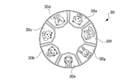
主玩具体10の前面中央には、円盤部50が設けられている。円盤部50の中央には回転軸が設けられており、遊技者の手動操作によって、前記回転軸を中心として回転するディスク30(図2参照)が設けられている。また、主玩具体10の側面部には、ディスク30の回転を停止させるストップボタン40が設けられている。図2に示すようにディスク30の円周上には、複数のキャラクタの出目(30a〜30g)が等間隔に配置されており、回転中、遊技者が停止操作によって確定された出目(30a〜30g)、すなわち、円盤部50に形成されている窓部50Aに位置づけられた出目に応じて、各出目固有の演出が出力される。
A
また、円盤部50の上面には浮き彫り状に形成されるレリーフ60が設けられ、このレリーフ60は、円盤部50に対して前記回転軸21と同じ位置を中心に回動自在に設けられている。レリーフ60を手動で回転させることによって、演出形態が切り替わるマイクロスイッチ(図示せず)が内蔵され、後述する第1モード(必殺モード)と第2モード(変身モード)との間で可逆的に演出の形態が変化する。演出は、モード別(第1モード又は第2モード)と出目(30a〜30g)との組合せに応じて決定され、モードによって異なる各出目に応じた演出が出力される。
In addition, a
演出出力玩具1は、遊技者が主玩具体10のディスク30を回転させ、ストップボタン40を押下することでディスク30を停止して、出目(30a〜30g)が確定する。これにより、音声、光及び映像の少なくとも1つによる演出が行われ、遊技者が、例えば、必殺技や変身の発動を疑似体験することを可能とする。
In the effect output toy 1, the player rotates the
なお、遊技者の手動操作によってディスク30が回転するため、回転開始後、時間とともに回転速度が減少する。そのため、遊技者は、遊技者の好きなキャラクタへの目押しが可能となり、ランダムに出目を検出し、演出を行う本玩具の特徴を損ねる恐れがある。そこで、タイマ(図4の符号16)を内蔵させ、遊技者によって、ディスク30が回転されると、回転が開始されてからストップボタン40の押下を検知するまでの回転時間を計測する。そして、予め時間を設定し、設定した時間内であれば、正常と判定し、演出が出力され、タイマがタイムアウトして設定した時間を経過した場合は、ディスク30の回転開始後、回転速度が減少して、遊技者が自ら出目を調整することが可能な状態になってから停止させたものとして、エラーと判定し、演出が行われない。
Since the
次に確定された出目(30a〜30g)を検出する機構について、図3を参照しながら説明する。図3(a)、(b)、(c)に示すように、主玩具体10は、ディスク30に固定され、ディスク30の回転軸21と同軸上で回転可能な3以上の回転部材22と、この回転部材22のそれぞれと対向して離間した位置に設けられた3以上の検出スイッチ15(本発明にいう「検出手段」、以降、マイクロスイッチ15と呼ぶ)とを備えている。なお、3以上の回転部材22は、回転軸21と平行な方向に配列されており、また、3以上の検出スイッチ15もこれと対向するように、回転軸21と平行となる方向に配列されている。各回転部材22には、径方向にそれぞれ凸部(本発明にいう「被検出部」)が設けられており、それぞれの凸部がディスク30の回転に伴い、対向して位置するそれぞれのマイクロスイッチ15を押圧する構造になっている。
Next, a mechanism for detecting the determined outcome (30a to 30g) will be described with reference to FIG. As shown in FIGS. 3A, 3 </ b> B, and 3 </ b> C, the
各回転部材22は、凸部の有無について、グレイコードに準ずるように互いに組合せがなされている。遊技者の操作により、ディスク30が回転すると、同軸上に設けられている回転部材22も回転し、この回転部材22の凸部がマイクロスイッチ15を押下することで対向して位置するマイクロスイッチ15がON状態になる。マイクロスイッチ15が押されたことにより、ディスク30が回転されたことを検出する。
Each rotating
本実施形態では、例えば、3つの回転部材22とこれら回転部材22に対応する3つのマイクロスイッチ15を備える例を説明する。マイクロスイッチ15が押下されている場合(ON)を“1”、押下されていない場合(OFF)を“0”とすれば、グレイコードを適用した場合、3ビットの組合せ(凸部による検出スイッチ(マイクロスイッチ15)の押圧状態、本発明にいう「3つ以上の検出手段における被検出部の検出状態」)は、(0,0,1)、(0,1,1)、(0,1,0)、(1,1,0)、(1,1,1)、(1,0,1)、(1,0,0)と7種類となり(ただし、(0,0,0)を除く)、この順番で切り換わり、また繰り返される。すなわち、これらの情報(本発明にいう「3つ以上の検出手段における被検出部の検出状態」)は、ディスク30に配置された複数のキャラクタ、すなわち、出目のそれぞれに対応している。換言すれば、凸部(本発明にう「被検出部」)は、これらの情報(本発明にいう「3つ以上の検出手段における被検出部の検出状態」)がディスク30に配置された複数のキャラクタ(出目)のそれぞれに対応して複数存在し得るように、3つの回転部材22のそれぞれにおいて設けられていることになる。また、グレイコードを適用することで、一般的な2進数を適用する場合と比べ、3個のビットのうち、常に1ビットしか変化しないため、誤り誤差が生成されない。また、2進数の場合、複数ビットのうち、1ビットしか変化しない場合もあるが2ビットあるいはそれ以上のビットが変化する場合がある。グレイコードを用いることで、稼動する機構、例えばスイッチ等の押下される回数が減少されるため、耐久性があがる。また、グレイコードを用いることで、正転または反転の回転方向の検出が可能である。また、グレイコードを用いることで、正転、反転のいずれか1方向への回転運動が連続しているか否かの検出が可能である。そのため、例えば遊技者が好きな出目を出すために故意にディスクを操作して回転方向を変えた場合はエラーと判定し、演出を行わない等の処理を行うことができる。
In the present embodiment, for example, an example in which three
図4は、本発明に係る実施形態の演出出力玩具の内部構成を示すブロック図である。図4に示すように、主玩具体10は、制御部11と、出力部12と、モード検出部(モード検出手段)13と、スイッチ判定部14と、マイクロスイッチ15と、タイマ16と、電池17と、電源スイッチ18と、ストップボタン40と、レリーフ60と、から構成される。
FIG. 4 is a block diagram showing an internal configuration of the effect output toy according to the embodiment of the present invention. As shown in FIG. 4, the
遊技者によって、主玩具体10のディスク30が回転され、遊技者によってストップボタン40が押下される(つまり、ディスク30(表示体)が停止される)と、スイッチ判定部14によって、いずれかの回転部材22の凸部によって押圧されたマイクロスイッチ15の状態(凸部による検出スイッチ(マイクロスイッチ15)の押圧状態、本発明にいう「3つ以上の検出手段における被検出部の検出状態」)を判定する。制御部11は、マイクロスイッチ15の状態に応じて、出力部12へ音声、光及び映像の少なくとも一つによる演出パターンを出力する。なお、このとき遊技者から見ると、停止時に窓部50Aに位置づけられている出目(出目30a〜30g)に応じた演出パターンが選択されて出力されているかのように見える。
When the player rotates the
出力部12は、発音部12aと、発光部12bと、表示部12cを備える。発音部12aは、例えば、音声による演出を出力するスピーカを含む。発光部12bは、例えば、複数の発光色(赤色、緑色、青色、黄色)のLED(Light Emitting Diode)で構成される。表示部12cは、例えば、LCD(Liquid Crystal Display)や有機EL(Organic Electro-Luminescence)等により構成されている。出力部12は、遊技者の演出出力玩具1の操作に応じて、制御部11からの制御により音声、光及び映像の少なくとも一つによる演出パターンを出力する。
The
モード検出部13は、レリーフ60の回転によって切り換わる第1モードと第2モードのいずれかの形態を検出する。例えば、2個のマイクロスイッチを使用し、レリーフ60の形態に応じて押されるマイクロスイッチのON/OFF状態により検出される。
The
タイマ16は、遊技者によって、ディスク30が回転されると、回転が開始されてからストップボタン40の押下を検知するまでの回転時間を計測する。上述した不正防止のために、予め時間を設定し、設定した時間内であれば、制御部11に正常判定を送信し、タイマ16がタイムアウトして設定した時間を過ぎた場合は、エラー信号を制御部11に送信する。
When the
電池17は、主玩具体10の内部に設けられ、この電池17と制御部11は、電源スイッチ18を介して接続される。電源スイッチ18をONにすると、制御部11に電力が供給されて以下に説明する制御が実行される。
The
図5は、本発明に係る実施形態の動作例を説明するフローチャートである。図5に示すように、演出出力玩具1の電源スイッチ18をONにすると(ステップS1)、モード検出部13は、レリーフ60に内蔵されているマイクロスイッチを検知し、現在のモード情報を制御部11に送信する。制御部11はレリーフ60の形態が第1モードの場合(ステップS2“必殺モード”)、ステップS3へ進む。
FIG. 5 is a flowchart for explaining an operation example of the embodiment according to the present invention. As shown in FIG. 5, when the
制御部11は、遊技者によってディスク30が回転され、回転を検知すると(ステップS3“YES”)、ディスク30が回転を開始してから停止するまでの時間を計測するため、タイマ16をスタートさせる(ステップS4)。タイマ16は、遊技者によってストップボタン40が押下されると、予め設定した時間内にストップボタン40が押されたか否かを判定する(ステップS5)。タイマ16は、設定した時間内にストップボタン40の押下が検知されると(ステップS5“YES”)、正常判定を制御部11に送信する。
When the
次に、スイッチ判定部14は、グレイコードに準じている形状の回転部材22の凸部によるマイクロスイッチ15の押圧状態(本発明にいう「3つ以上の検出手段における被検出部の検出状態」)を検出し(ステップS6)、その結果を制御部11に送信する。それに伴い、制御部11は、マイクロスイッチ15の状態(凸部による検出スイッチ(マイクロスイッチ15)の押圧状態、本発明にいう「3つ以上の検出手段における被検出部の検出状態」)を基に、それに応じた演出パターンを出力部12から出力させる(ステップS9)。また、設定時間内にストップボタン40が押されなかった場合(ステップS5“NO”)、タイマ16は、タイムアウトによるエラー信号を制御部11に送信する。このとき制御部11は、演出パターンの出力を行わず、ステップS3に処理を戻す。
Next, the
なお、制御部11は、レリーフ60の形態が変身モードの場合(ステップS2“変身モード”)、変身モードに応じた演出パターンを生成し、ステップS10以降については、必殺モードと同様の手順を進む。すなわち、制御部11は、遊技者によってディスク30が回転され、回転を検知すると(ステップS10“YES”)、ディスク30が回転を開始してから停止するまでの時間を計測するため、タイマ16をスタートさせる(ステップS11)。タイマ16は、遊技者によってストップボタン40が押下されると、予め設定した時間内にストップボタン40が押されたか否かを判定する(ステップS12)。タイマ16は、設定した時間内にストップボタン40の押下が検知されると(ステップS12“YES”)、正常判定を制御部11に送信する。
In addition, when the form of the
次に、スイッチ判定部14は、グレイコードに準じている形状の回転部材22の凸部によるマイクロスイッチ15の状態(凸部による検出スイッチ(マイクロスイッチ15)の押圧状態、本発明にいう「3つ以上の検出手段における被検出部の検出状態」)を検出し(ステップS13)、その結果を制御部11に送信する。それに伴い、制御部11は、マイクロスイッチ15の状態(凸部による検出スイッチ(マイクロスイッチ15)の押圧状態、本発明にいう「3つ以上の検出手段における被検出部の検出状態」)を基にそれに応じた演出パターンを出力部12から出力させる(ステップS16)。また、設定時間内にストップボタン40が押されなかった場合(ステップS12“NO”)、タイマ16は、タイムアウトによるエラー信号を制御部11に送信する。このとき制御部11は、演出パターンの出力を行わず、ステップS10に処理を戻す。
Next, the
以上に述べた本実施形態の演出出力玩具1によれば、回転可能なディスク30(本発明にいう「表示体」)と、ディスク30に固定され、ディスク30の回転軸と同軸上で回転可能な3つ以上の回転部材22と、回転部材22と離間した位置に設けられた3つ以上の検出スイッチ15(本発明にいう「検出手段」)を備え、各回転部材22がディスク30の回転と連動して対応する検出スイッチ15を押圧する凸部(本発明にいう「検出手段にて検出される被検出部」)を有し、ディスク30を停止した際に検出された凸部による検出スイッチ15の押圧状態(本発明にいう「3つ以上の検出手段における被検出部の検出状態」)に応じた音声、光及び映像の少なくとも1つから選択される演出を出力する。このとき遊技者から見ると、停止時に窓部50Aに位置づけられている出目(出目30a〜30g)に応じた演出パターンが選択されて出力されているかのように見える。このようにすることで、軸上に回転部材22と検出スイッチ15を回転軸と平行に配列するため、装置の小型化が可能となる。それに伴い、径方向にスペースが確保されるため、演出出力玩具1の内部に別の機構等を設けることも可能となる。
According to the production output toy 1 of the present embodiment described above, the disc 30 (the “display body” in the present invention) that can be rotated and the
また、各回転部材22が、凸部(本発明にいう「被検出部」)の有無について、グレイコードに準じるように互いに組合されている。グレイコードの場合、複数のビットのうち常に1ビットしか変化しない。例えば、2進数の場合、複数ビットのうち、1ビットしか変化しない場合もあるが2ビットあるいはそれ以上のビットが変化する場合がある。グレイコードを用いることで、稼動する機構、例えばスイッチ等の押下される回数が減少されるため、耐久性があがる。
Further, the rotating
また、さらに、互いに可逆的な第1モードと第2モードを検出するモード検出手段13を備え、演出が、モード検出手段13によって検出された第1モード又は第2モードとディスク30を停止した際の凸部による検出スイッチ15の押圧状態(本発明にいう「3つ以上の検出手段における被検出部の検出状態」)との組合せに応じて決定され、出力される。このようにすることで、2つのモードで異なる演出を出力することが可能となるため、飽きのない演出出力玩具1を提供できる。
In addition, it further comprises mode detecting means 13 for detecting the first mode and the second mode which are reversible with each other, and when the production stops the first mode or the second mode detected by the
以上、実施形態を用いて本発明を説明したが、本発明の技術的範囲は上記実施形態に記載の範囲には限定されないことは言うまでもない。上記実施形態に、多様な変更または改良を加えることが可能であることが当業者に明らかである。またその様な変更または改良を加えた形態も本発明の技術的範囲に含まれ得ることが、特許請求の範囲の記載から明らかである。例えば、本実施形態においては、表示体をディスクとして説明したがこれに限られない。何らかの形で複数の出目を表示できる表面を有するものであれば、多角柱や円柱の側面に出目を表示したものでも良い。また、多角形の外径を有する盤状のものとしても良い。また、検出手段を検出スイッチ、被検出部を凸部とし、検出手段による被検出部の検出状態を凸部による検出スイッチの押圧状態として説明したが、これに限られない。検出手段を赤外線受光部および赤外線発光部、被検出部を当該赤外線発光部からの赤外線を反射する反射部とし、検出手段による被検出部の検出状態を、赤外線受光部における反射部によって反射された赤外線の受光状態としても良い。 As mentioned above, although this invention was demonstrated using embodiment, it cannot be overemphasized that the technical scope of this invention is not limited to the range as described in the said embodiment. It will be apparent to those skilled in the art that various modifications or improvements can be added to the above-described embodiments. Further, it is apparent from the scope of the claims that the embodiments added with such changes or improvements can be included in the technical scope of the present invention. For example, in the present embodiment, the display body is described as a disk, but the present invention is not limited to this. As long as it has a surface that can display a plurality of outcomes in some form, it may be one that displays outcomes on the sides of a polygonal column or cylinder. Moreover, it is good also as a disk-shaped thing which has a polygonal outer diameter. Further, although the detection means is described as a detection switch, the detected portion is a convex portion, and the detection state of the detected portion by the detection means is described as the pressing state of the detection switch by the convex portion, the present invention is not limited to this. The detecting means is an infrared light receiving part and an infrared light emitting part, the detected part is a reflecting part that reflects infrared rays from the infrared light emitting part, and the detection state of the detected part by the detecting means is reflected by the reflecting part in the infrared light receiving part. An infrared light receiving state may be used.
1 演出出力玩具
10 主玩具体(バックル)
11 制御部
12 出力部
12a 発音部
12b 発光部
12c 表示部
13 モード検出部(モード検出手段)
14 スイッチ判定部
15 マイクロスイッチ(検出手段)
16 タイマ
17 電池
18 電源スイッチ
20 ベルト
21 回転軸
22 回転部材
30 ディスク(表示体)
30a〜30g 出目
40 ストップボタン
50 円盤部
50A 窓部
60 レリーフ
1
DESCRIPTION OF
14
16
30a-
Claims (3)
回転可能で、かつ、複数の出目が表面に設けられた表示体と、
前記表示体の回転に伴い前記表示体の回転軸と同軸上で回転可能で、回転軸と平行な方向に配列された3つ以上の回転部材と、
前記回転部材と対向して離間した位置に設けられた検出手段を備え、
各回転部材には、前記表示体の回転と連動して前記検出手段にて検出される被検出部が設けられており、
前記被検出部は、前記検出手段における前記被検出部の検出状態が前記複数の出目のそれぞれに対応して複数存在し得るように各回転部材に設けられており、
前記表示体を停止した際に検出された前記検出手段における前記被検出部の検出状態に応じて、音声、光及び映像の少なくとも1つから選択される演出を出力することを特徴とする演出出力玩具。 A production output toy,
A display body that is rotatable and has a plurality of features on the surface;
Three or more rotating members that are rotatable coaxially with the rotation axis of the display body along with the rotation of the display body and are arranged in a direction parallel to the rotation axis ;
Includes a detecting means provided at a position spaced said rotary member and opposed to,
Each rotary member has the detection portion is provided to be detected by the prior Symbol detection means in conjunction with the rotation of the display member,
The detected part is detected state of the detection target portion before dangerous detecting means is provided on each rotating member so as to more exists corresponding to each of the plurality of dice,
Wherein in response to the detection state of the detection unit in danger detection means before being detected when stopping the display body, and outputs an effect selected voice, from at least one light and video Production output toy.
前記演出が、前記モード検出手段によって検出された前記第1モード又は前記第2モードと前記表示体を停止した際に検出された前記検出手段における前記被検出部の検出状態との組合せに応じて決定され、出力されることを特徴とする請求項1又は2に記載の演出出力玩具。
Furthermore, it comprises mode detecting means for detecting the first mode and the second mode which are reversible with each other,
The effect is the combination of the detection state of the detection target portion in danger detection means before being detected when stopping the display body and said detected first mode or said second mode by said mode detecting means The production output toy according to claim 1, wherein the production output toy is determined and output accordingly.
Priority Applications (1)
| Application Number | Priority Date | Filing Date | Title |
|---|---|---|---|
| JP2015009091A JP6270163B2 (en) | 2015-01-21 | 2015-01-21 | Production output toy |
Applications Claiming Priority (1)
| Application Number | Priority Date | Filing Date | Title |
|---|---|---|---|
| JP2015009091A JP6270163B2 (en) | 2015-01-21 | 2015-01-21 | Production output toy |
Related Parent Applications (1)
| Application Number | Title | Priority Date | Filing Date |
|---|---|---|---|
| JP2014082407A Division JP5694587B1 (en) | 2014-04-14 | 2014-04-14 | Production output toy |
Publications (3)
| Publication Number | Publication Date |
|---|---|
| JP2015202399A JP2015202399A (en) | 2015-11-16 |
| JP2015202399A5 JP2015202399A5 (en) | 2017-06-08 |
| JP6270163B2 true JP6270163B2 (en) | 2018-01-31 |
Family
ID=54596236
Family Applications (1)
| Application Number | Title | Priority Date | Filing Date |
|---|---|---|---|
| JP2015009091A Active JP6270163B2 (en) | 2015-01-21 | 2015-01-21 | Production output toy |
Country Status (1)
| Country | Link |
|---|---|
| JP (1) | JP6270163B2 (en) |
Families Citing this family (2)
| Publication number | Priority date | Publication date | Assignee | Title |
|---|---|---|---|---|
| JP6876371B2 (en) * | 2016-02-18 | 2021-05-26 | 株式会社タイトー | Input device |
| JP7102575B1 (en) * | 2021-04-14 | 2022-07-19 | 株式会社バンダイ | Directing output toys |
Family Cites Families (6)
| Publication number | Priority date | Publication date | Assignee | Title |
|---|---|---|---|---|
| JP3489061B2 (en) * | 1993-02-26 | 2004-01-19 | 株式会社ニューギン | Information coding type strip design display member |
| JP3145354B2 (en) * | 1998-06-01 | 2001-03-12 | コナミ株式会社 | Game console input device |
| JP3742306B2 (en) * | 2001-02-28 | 2006-02-01 | コナミ株式会社 | Roulette game system and program |
| US7771247B2 (en) * | 2005-05-25 | 2010-08-10 | Kessler Brian D | Novelty light-up toy |
| JP4845229B1 (en) * | 2010-10-29 | 2011-12-28 | 株式会社バンダイ | Information reading toy |
| JP5122014B1 (en) * | 2012-06-26 | 2013-01-16 | 株式会社バンダイ | Motion responsive toy and toy body |
-
2015
- 2015-01-21 JP JP2015009091A patent/JP6270163B2/en active Active
Also Published As
| Publication number | Publication date |
|---|---|
| JP2015202399A (en) | 2015-11-16 |
Similar Documents
| Publication | Publication Date | Title |
|---|---|---|
| JP5694587B1 (en) | Production output toy | |
| US20200009451A1 (en) | Tracking three-dimensional puzzle components using embedded signature and rotation sensors | |
| US7397387B2 (en) | Light sculpture system and method | |
| US8987620B2 (en) | Haptic steering wheel switch apparatus | |
| JP6270163B2 (en) | Production output toy | |
| US10533879B2 (en) | Optical encoder with axially aligned sensor | |
| JP7375095B2 (en) | production output toy | |
| FR2876813A1 (en) | VIDEO PLAY CONTROL DEVICE WITH INTEGRATED GARBAGE BALL CONTROL MEMBER. | |
| US20150213975A1 (en) | Switch device | |
| JP4667313B2 (en) | Observation device with polarized illumination | |
| US20130249811A1 (en) | Controlling a device with visible light | |
| US8991691B2 (en) | System and method for interactive mobile gaming | |
| WO2017037302A1 (en) | A remote control device | |
| CN109870179A (en) | Optical facilities for rotational positioning | |
| JP4240774B2 (en) | Rotation angle detection device and rotation angle detection method | |
| TW201043316A (en) | Turntable-type input device, method for determining input operation of turntable-type input device, and program for turntable-type input device | |
| WO2021059878A1 (en) | Game system, method of controlling same, and computer program | |
| US10894205B2 (en) | Puzzle device | |
| JP2011125391A (en) | Button unit for game machine | |
| WO2022220202A1 (en) | Performance output toy | |
| JP3120911U (en) | Rotating wheel array light display device | |
| US9976637B2 (en) | Rotary electric component | |
| US7857231B2 (en) | Rotatable disc and method for adjusting its orientation | |
| CN114307196A (en) | Information holding medium and performance output toy | |
| JPS5946793B2 (en) | Type setting method |
Legal Events
| Date | Code | Title | Description |
|---|---|---|---|
| A521 | Request for written amendment filed |
Free format text: JAPANESE INTERMEDIATE CODE: A523 Effective date: 20170412 |
|
| A621 | Written request for application examination |
Free format text: JAPANESE INTERMEDIATE CODE: A621 Effective date: 20170412 |
|
| TRDD | Decision of grant or rejection written | ||
| A977 | Report on retrieval |
Free format text: JAPANESE INTERMEDIATE CODE: A971007 Effective date: 20171215 |
|
| A01 | Written decision to grant a patent or to grant a registration (utility model) |
Free format text: JAPANESE INTERMEDIATE CODE: A01 Effective date: 20171221 |
|
| A61 | First payment of annual fees (during grant procedure) |
Free format text: JAPANESE INTERMEDIATE CODE: A61 Effective date: 20171221 |
|
| R150 | Certificate of patent or registration of utility model |
Ref document number: 6270163 Country of ref document: JP Free format text: JAPANESE INTERMEDIATE CODE: R150 |
|
| R250 | Receipt of annual fees |
Free format text: JAPANESE INTERMEDIATE CODE: R250 |
|
| R250 | Receipt of annual fees |
Free format text: JAPANESE INTERMEDIATE CODE: R250 |
|
| R250 | Receipt of annual fees |
Free format text: JAPANESE INTERMEDIATE CODE: R250 |