JP6263769B2 - LED power supply device and LED lighting device - Google Patents
LED power supply device and LED lighting device Download PDFInfo
- Publication number
- JP6263769B2 JP6263769B2 JP2013254691A JP2013254691A JP6263769B2 JP 6263769 B2 JP6263769 B2 JP 6263769B2 JP 2013254691 A JP2013254691 A JP 2013254691A JP 2013254691 A JP2013254691 A JP 2013254691A JP 6263769 B2 JP6263769 B2 JP 6263769B2
- Authority
- JP
- Japan
- Prior art keywords
- input
- capacitor
- power supply
- led
- capacitors
- Prior art date
- Legal status (The legal status is an assumption and is not a legal conclusion. Google has not performed a legal analysis and makes no representation as to the accuracy of the status listed.)
- Active
Links
Images
Landscapes
- Circuit Arrangement For Electric Light Sources In General (AREA)
Description
本発明はLED電源装置及びそれを用いたLED照明装置に関する。 The present invention relates to an LED power supply device and an LED lighting device using the LED power supply device.
特許文献1はいわゆるコンデンサインプット型の照明用電源回路を開示する。同文献の電源回路(1)は、交流電源が入力される全波整流器(DB1)と、全波整流器の出力端に並列接続された平滑コンデンサ(C2)と、平滑コンデンサを電源としてLED電流を生成するDC/DCコンバータ(33)を備える。このようなコンデンサインプット型の回路においては、交流電源電圧のピーク付近でしか入力電流が発生しないため、入力力率が低い。 Patent Document 1 discloses a so-called capacitor input type illumination power supply circuit. The power supply circuit (1) of the same document includes a full-wave rectifier (DB1) to which an AC power supply is input, a smoothing capacitor (C2) connected in parallel to the output terminal of the full-wave rectifier, and LED current using the smoothing capacitor as a power source. A DC / DC converter (33) for generation is provided. In such a capacitor input type circuit, since an input current is generated only near the peak of the AC power supply voltage, the input power factor is low.
特許文献2はいわゆる力率改善型のLED点灯回路を開示する。同文献のLED点灯回路は、交流電源が入力される全波整流器(DB)と、全波整流器の出力端に並列接続された第1のコンデンサ(C1)と、第1のコンデンサを電源としてLED電流を生成するスイッチング電源部(1)と、LED電流を平滑化する第2のコンデンサ(C2)を備える。第1のコンデンサが1μ未満に設定されることにより、交流電源電圧のほぼ全範囲で入力電流が発生し、特許文献1のようなコンデンサインプット型の回路に比べて入力力率が改善される。
しかし、特許文献2に開示されるような構成によると、全波整流器の出力端に並列接続されるコンデンサ(以下、「入力コンデンサ」という)の小容量化によって、入力コンデンサの寿命設計が難しくなる。具体的には、入力コンデンサには、通常動作時にはDC/DCコンバータのスイッチング動作による高周波電流が流れ、交流電源投入時には突入電流が流れる。一般的に、コンデンサの容量値の減少に対して許容電流も減少するため、入力コンデンサの低容量化によって許容電流に対するディレーティングが困難となる。ここで、一般に同じ種類のコンデンサに関して、容量を半分とすると許容電流は半分以上となる。従って、入力コンデンサを2つのコンデンサの並列回路として、各コンデンサの容量を1つのコンデンサの場合の半分にすれば入力力率を維持しつつコンデンサのディレーティングの問題を解決できるかのようにみえる。しかし、実際には、コンデンサ容量のばらつき、電流源からコンデンサまでの経路のインピーダンスの差等に起因して、並列接続された2つのコンデンサに電流は均等には流れない。従って、より多くの電流が流れる方のコンデンサが先に寿命に達することになる。その結果として、所期の回路寿命設計が実現されない場合がある。
However, according to the configuration disclosed in
そこで、本発明は、高い入力力率を実現しつつも入力コンデンサのディレーティングを確保し、かつ入力コンデンサに流れる電流を均等に分流して回路の正確な寿命設計を可能とするLED電源装置及びそれを用いたLED照明装置を提供することを課題とする。 Therefore, the present invention provides an LED power supply device that ensures derating of an input capacitor while realizing a high input power factor, and that evenly diverts the current flowing through the input capacitor to enable an accurate circuit life design. It is an object to provide an LED lighting device using the same.
本発明のLED電源装置は、第1の入力端、第2の入力端、第1の出力端及び第2の出力端を有し、第1及び第2の入力端に交流電圧が入力される全波整流器と、第1の入力端と第1の出力端との間に接続された第1の入力コンデンサ及び第2の入力端と第1の出力端との間に接続された第2の入力コンデンサを有し、第1の入力コンデンサ及び第2の入力コンデンサの容量が等しく、その容量は入力力率が99.0%以上となるように設定された入力コンデンサ回路と、第1の入力コンデンサ及び第2の入力コンデンサの電圧をスイッチング、変圧、整流及び平滑化して直流電流をLEDに供給するように構成されたDC/DCコンバータとを備える。 The LED power supply device of the present invention has a first input terminal, a second input terminal, a first output terminal, and a second output terminal, and an AC voltage is input to the first and second input terminals. A full-wave rectifier, a first input capacitor connected between the first input end and the first output end, and a second input connected between the second input end and the first output end An input capacitor circuit having an input capacitor, wherein the first input capacitor and the second input capacitor have the same capacitance, and the capacitance is set so that the input power factor is 99.0% or more; A DC / DC converter configured to switch, transform, rectify and smooth the voltage of the capacitor and the second input capacitor to supply a direct current to the LED.
上記のLED電源装置によると、全波整流器の1つの出力端から一方の入力端に第1の入力コンデンサが接続され、同出力端から他方の入力端に第2の入力コンデンサが接続され、入力力率が99.0%となるように双方の入力コンデンサの容量が設定される。従って、高い入力力率が実現されるとともに、DC/DCコンバータのスイッチングによる高周波電流及び交流電源投入時の突入電流が第1及び第2のコンデンサに均等に流れる構成が実現され、入力コンデンサのディレーティングの確保及び回路の正確な寿命設計が可能となる。 According to the LED power supply device described above, the first input capacitor is connected from one output end of the full-wave rectifier to one input end, and the second input capacitor is connected from the output end to the other input end. The capacities of both input capacitors are set so that the power factor is 99.0%. Therefore, a high input power factor is realized, and a configuration in which a high-frequency current due to switching of the DC / DC converter and an inrush current when the AC power is turned on flows evenly to the first and second capacitors is realized. It is possible to ensure the rating and design the life of the circuit accurately.
ここで、第1の出力端は高電位側であり、第2の出力端は低電位側とすることが好ましい。これにより、全波整流器とDC/DCコンバータの間の低電位側の電流経路にコンデンサが接続されないので、低電位側の直流ラインに接続されるシグナルグランドの設計自由度が増し、回路の配線設計が容易となる。また、コモンモードの雷サージが印加されて高電位側出力端から交流電源に向かうサージ電流が発生した場合でも、サージ電流は全波整流器を経由せずに第1及び第2の入力コンデンサを経由して流れるので、全波整流器が故障することはない。これにより、LED電源装置の信頼性が向上する。 Here, it is preferable that the first output terminal is on the high potential side and the second output terminal is on the low potential side. As a result, a capacitor is not connected to the current path on the low potential side between the full-wave rectifier and the DC / DC converter, increasing the degree of freedom in designing the signal ground connected to the DC line on the low potential side, and designing the circuit wiring Becomes easy. Even when a common mode lightning surge is applied and a surge current is generated from the output terminal on the high potential side to the AC power supply, the surge current does not pass through the full-wave rectifier and passes through the first and second input capacitors. The full-wave rectifier will not fail. Thereby, the reliability of the LED power supply device is improved.
また、第1の入力コンデンサ及び第2の入力コンデンサの容量はそれぞれ0.01μF以上1μF以下であることが好ましい。これにより、第1及び第2のコンデンサがDC/DCコンバータの電源として機能し、かつ高い入力力率が実現される。 Moreover, it is preferable that the capacity | capacitance of a 1st input capacitor and a 2nd input capacitor is 0.01 micro F or more and 1 micro F or less, respectively. Thereby, the first and second capacitors function as a power source for the DC / DC converter, and a high input power factor is realized.
ここで、全波整流器がリード挿入型のブリッジダイオードからなり、第1及び第2の入力コンデンサがそれぞれ第1及び第2のフィルムコンデンサからなり、ブリッジダイオード、第1及び第2のフィルムコンデンサ並びにDC/DCコンバータの各素子が実装された基板において、第1及び第2の入力端にそれぞれ接続される第1及び第2の交流パターンがブリッジダイオードの主面に対して第1の方向に延在するように配線され、第1及び第2の出力端にそれぞれ接続される第1及び第2の直流パターンが上記主面に対して第1の方向とは逆の第2の方向に延在するように配線され、基板の上面視において、ブリッジダイオードと第1及び第2の直流パターンで画定される領域において、第1のフィルムコンデンサの長手方向及び第2のフィルムコンデンサの長手方向がブリッジダイオードの主面に対して垂直になるように第1及び第2のフィルムコンデンサが配置されるようにした。これにより、比較的短いパターンによる第1及び第2の入力コンデンサの接続が可能となるとともに、第1及び第2の入力コンデンサが全波整流器及びDC/DCコンバータから受ける輻射熱の影響が均一化される。 Here, the full-wave rectifier comprises a lead insertion type bridge diode, the first and second input capacitors comprise first and second film capacitors, respectively, and the bridge diode, the first and second film capacitors, and the DC The first and second AC patterns connected to the first and second input terminals respectively extend in the first direction with respect to the main surface of the bridge diode on the substrate on which each element of the DC / DC converter is mounted. And the first and second DC patterns connected to the first and second output terminals respectively extend in a second direction opposite to the first direction with respect to the main surface. In the region defined by the bridge diode and the first and second DC patterns in the top view of the substrate, the longitudinal direction of the first film capacitor and the second Longitudinal I Lum capacitor is so that first and second film capacitor is arranged perpendicular to the main surface of the bridge diode. As a result, the first and second input capacitors can be connected in a relatively short pattern, and the influence of the radiant heat that the first and second input capacitors receive from the full-wave rectifier and the DC / DC converter is made uniform. The
また、全波整流器がリード挿入型のブリッジダイオードからなり、第1及び第2の入力コンデンサがそれぞれ第1及び第2のフィルムコンデンサからなり、ブリッジダイオード、第1及び第2のフィルムコンデンサ並びにDC/DCコンバータの各素子が実装された基板の上面視において、ブリッジダイオードの長手方向を挟んで対向する位置において、第1のフィルムコンデンサの長手方向及び第2のフィルムコンデンサの長手方向がブリッジダイオードの長手方向に垂直となるように第1及び第2のフィルムコンデンサが配置されるようにしてもよい。これにより、第1及び第2の入力コンデンサが全波整流器及びDC/DCコンバータから受ける輻射熱の影響が均一化及び軽減される。 The full-wave rectifier includes a lead insertion type bridge diode, and the first and second input capacitors include first and second film capacitors, respectively. The bridge diode, the first and second film capacitors, and the DC / DC In the top view of the substrate on which each element of the DC converter is mounted, the longitudinal direction of the first film capacitor and the longitudinal direction of the second film capacitor are the longitudinal direction of the bridge diode at positions facing each other across the longitudinal direction of the bridge diode. You may make it arrange | position a 1st and 2nd film capacitor so that it may become perpendicular | vertical to a direction. Thereby, the influence of the radiant heat which a 1st and 2nd input capacitor receives from a full wave rectifier and a DC / DC converter is equalized and reduced.
上記において、DC/DCコンバータが、第1及び第2の出力端のうちの一方が接続される1次巻線及び該一次巻線から絶縁された2次巻線を有するトランスと、1次巻線をスイッチングするスイッチング素子と、2次巻線の出力を整流するダイオードと、LEDに並列接続されてダイオードの出力を平滑化する平滑コンデンサと、スイッチング素子を駆動する制御回路を含む。これにより、少ない部品点数で小型かつ低コストなLED電源装置が構成される。 In the above, the DC / DC converter includes a transformer having a primary winding to which one of the first and second output ends is connected and a secondary winding insulated from the primary winding, and the primary winding. It includes a switching element that switches lines, a diode that rectifies the output of the secondary winding, a smoothing capacitor that is connected in parallel to the LED and smoothes the output of the diode, and a control circuit that drives the switching element. Thereby, a small and low-cost LED power supply device is configured with a small number of parts.
本発明のLED照明装置は、上記のLED電源装置とLEDとを備える。これにより高い入力力率でかつ寿命が確保されたLED照明装置を得ることができる。 The LED lighting device of the present invention includes the LED power supply device and the LED described above. As a result, it is possible to obtain an LED lighting device having a high input power factor and a long lifetime.
実施形態1.
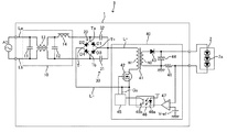
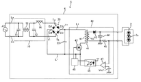
図1に、本発明の実施形態1に係るLED電源装置1を含むLED照明装置3の回路構成図を示す。LED照明装置3はLED電源装置1及びLED2を含む。LED電源装置1には交流電源ACが入力され、LED電源装置1から直流出力がLED2に供給される。LED2は直列接続された複数のLED素子2aからなるLEDモジュール等であればよい。図1においては、3個のLED素子2aを示しているが、LED素子2aの接続数は任意である。
Embodiment 1. FIG.
In FIG. 1, the circuit block diagram of the LED lighting apparatus 3 containing the LED power supply device 1 which concerns on Embodiment 1 of this invention is shown. The LED lighting device 3 includes an LED power supply device 1 and an
LED電源装置1は、入力回路10、全波整流器20、入力コンデンサ回路30及びDC/DCコンバータ40を含む。なお、本明細書における説明において、各回路又は構成要素が上記のどのブロックに属するかは便宜的なものであり、本発明を拘束するものではない。また、同様の構成要素には同じ符号を付し、重複する説明を省略する。
The LED power supply device 1 includes an
入力回路10は、フィルタコンデンサ11及び12、コモンモードチョークコイル13並びにノーマルモードチョークコイル14を含み、全体としてノイズフィルタを構成する。なお、入力回路10は、必要に応じて電流ヒューズ、バリスタ等をさらに含んでいてもよい。
The
全波整流器20はダイオードD1、D2、D3及びD4を含むダイオードブリッジからなる。以降の説明において、ダイオードD1のアノードとダイオードD2のカソードの接続点を入力端Taといい、ダイオードD3のアノードとダイオードD4のカソードの接続点を入力端Tbというものとする。入力端Taはノーマルモードチョークコイル14側の交流ラインLaに接続され、入力端Tbは他方の交流ラインLbに接続される。また、ダイオードD1のカソードとダイオードD3のカソードの接続点を高電位側出力端T+といい、ダイオードD2のアノードとダイオードD4のアノードの接続点を低電位側出力端T−というものとする。高電位側出力端T+は直流ラインL+に接続され、低電位側出力端T−は直流ラインL−に接続される。交流電源ACからの入力電圧が全波整流器20によって全波整流され、全波整流出力が直流ラインL+及びL−を介してDC/DCコンバータ40に入力される。
The
入力コンデンサ回路30は入力コンデンサ31及び32を含む。入力コンデンサ31は全波整流器20の高電位側出力端T+と入力端Tbの間に接続され、入力コンデンサ32は高電位側出力端T+と入力端Taの間に接続される。入力コンデンサ31は、交流ラインLaが交流ラインLbに対して正側となる場合に、後述するDC/DCコンバータ40にスイッチング電流を供給する役割を担う(すなわち、DC/DCコンバータ40の電源となる)。具体的には、入力コンデンサ31は、交流ラインLa→ダイオードD1→入力コンデンサ31→交流ラインLbに電流が流れることにより充電され、入力コンデンサ31→直流ラインL+→DC/DCコンバータ40→直流ラインL−→ダイオードD4に電流が流れることにより放電される。一方、入力コンデンサ32は、入力端Tbが入力端Taに対して正側となる場合にDC/DCコンバータ40の電源となる。具体的には、入力コンデンサ32は、交流ラインLb→ダイオードD3→入力コンデンサ32→交流ラインLaに電流が流れることにより充電され、入力コンデンサ32→直流ラインL+→DC/DCコンバータ40→直流ラインL−→ダイオードD2に電流が流れることにより放電される。
入力コンデンサ31と入力コンデンサ32の容量は等しく、その容量は、適用される交流電源電圧範囲において入力力率が99.0%以上となるように設定される。特に、適用される交流電源電圧が100Vac〜242Vacである場合に、入力力率が99.0%以上となるように入力コンデンサ31及び32の容量が設定されることが好ましい。なお、LED電源装置1の入力電力が1W以上150W以下の範囲において、入力コンデンサ31及び32の容量はそれぞれ1μF以下であることが好ましい。これは、入力コンデンサ31及び32の容量がそれぞれ1μFを超える場合、電源電圧の谷部での入力電流が減少する一方で電源電圧のピーク付近での入力電流が増加し、特に高い交流電源電圧でかつ入力電力が小さい場合に入力力率が低くなるからである。また、LED電源装置1の入力電力が1W以上150W以下の範囲において、入力コンデンサ31及び32の容量は許容実効電流値を満たす範囲でそれぞれ0.01μF以上であることが好ましい。これは、入力コンデンサ31及び32の容量が0.01μF未満の場合、特に低い交流電源電圧でかつ入力電力が大きい場合にDC/DCコンバータ40の電源として機能しなくなるからである。
The capacities of the
DC/DCコンバータ40は、トランス41、スイッチング素子42、ダイオード43、平滑コンデンサ44、制御回路45、フォトカプラ46、誤差増幅器47及び電流検出抵抗48を含む。DC/DCコンバータ40は絶縁型フライバックコンバータからなり、力率改善機能を持つ、いわゆるワンコンバータ方式のフライバック降圧回路を構成する。これにより、少ない部品点数で小型かつ低コストなLED電源装置が実現される。概略として、DC/DCコンバータ40は入力コンデンサ31及び32の電圧をスイッチング、変圧、整流及び平滑化して直流電流をLED2に供給し、その直流出力は以下に説明するように定電流制御される。
The DC /
DC/DCコンバータ40において、スイッチング素子42のオン期間にトランス41の一次巻線N1によってエネルギーが蓄積され、スイッチング素子42のオフ期間にそのエネルギーがトランス41の二次巻線N2側からダイオード43を介して平滑コンデンサ44に充電される。降圧比は一次巻線N1に対する二次巻線N2の巻数比によって決まり、出力電流はスイッチング素子42のPWM制御におけるオンデューティ(オン幅)によって決まる。平滑コンデンサ44はLED2に並列接続され、ダイオード43からの整流出力を平滑化する。平滑コンデンサ44は、許容される光リップルに応じて100μF〜1000μF程度であればよい。
In the DC /
制御回路45はドライバIC及びその周辺回路を含み、スイッチング素子42を100kHz程度の高周波でPWM駆動する。制御回路45はフォトカプラ46のフォトトランジスタ46bの出力状態に応じたパルス幅(すなわち、オンデューティ)のPWM駆動信号を生成し、それをスイッチング素子42のゲート電圧として出力する。フォトカプラ46のフォトダイオード46aのアノードには所定の電流又は電圧が供給され、フォトトランジスタ46bには、フォトダイオード46aに流れる電流(発光)に応じた出力電流が流れる。誤差増幅器47において、電流検出抵抗48に発生する電圧(電流検出値)が負入力端子に入力され、基準電圧Vrefが正入力端子に入力される。なお、誤差増幅器47の負入力端子と出力端子間には不図示の帰還素子(抵抗、コンデンサ、又はこれらの直列回路若しくは並列回路)が接続されるものとする。誤差増幅器47は、負入力端子の入力値と正入力端子の入力値との誤差を増幅して出力し、その誤差がなくなる方向にPWM制御のパルス幅が決定される。すなわち、制御回路45、フォトカプラ46、誤差増幅器47等の協働によってDC/DCコンバータ40の出力電流がフィードバック制御され、LED電流が設定値で一定となるように制御される。
The
DC/DCコンバータ40は、スイッチング電流に休止期間がある不連続モード、又はスイッチング電流に休止期間がなくかつスイッチング電流がゼロまで低下する臨界モードのいずれかで動作され得るが、本実施形態では不連続モードが採用される。図2に、スイッチング素子42に流れるスイッチング電流と交流電源ACからの入力電流の関係を、電源電圧の半波分について示す。交流電源ACの電圧位相の全域にわたってスイッチング素子42が高周波(例えば100kHz程度)で駆動される。なお、図2は各波形を模式的に示すものであり、電源電圧の半波波形中に10波のスイッチング電流のみを示しているが、実際には、交流電源ACが50Hzでスイッチング周波数が100kHzである場合に、電源電圧の半波波形中に1000波のスイッチング電流が含まれることになる。これにより、交流電源電圧に応じて交流入力電流が平均化されて入力電流波形がほぼ正弦波となり、高い入力力率が得られるとともに電源高調波が抑制される。
The DC /
ここで、以降の説明において比較例となるLED電源装置について説明する。図10は比較例のLED電源装置4を含むLED照明装置5の回路構成図である。図1に示すLED電源装置1からの相違は、図1の入力コンデンサ31及び32の代わりに入力コンデンサ33が全波整流器20の高電位側出力端T+(直流ラインL+)と低電位側出力端T−(直流ラインL−)の間に接続された点である。入力コンデンサ33には、全波整流器20からの全波整流出力である全波の脈流電圧が印加され、その充電電圧がDC/DCコンバータ40の電源となる。
Here, an LED power supply device as a comparative example will be described in the following description. FIG. 10 is a circuit configuration diagram of the LED lighting device 5 including the LED power supply device 4 of the comparative example. The difference from the LED power supply device 1 shown in FIG. 1 is that the
図11に、入力コンデンサ33を流れる電流を交流電源電圧の2周期分について示す。図11に示すように、入力コンデンサ33には、全波脈流電圧の高周波スイッチングの結果として、全波整流器20の全波整流出力を包絡線とする高周波電流が流れる。
FIG. 11 shows the current flowing through the
一方、図3に、LED電源装置1の入力コンデンサ31及び32を流れる電流を交流電源電圧の2周期分について示す。半波脈流電圧の高周波スイッチングの結果として、入力コンデンサ31及び32には、全波整流器20の半波整流出力を包絡線とする高周波電流が半波ごとに流れる。入力コンデンサ31及び32の各々における電流の通電時間は入力コンデンサ33における通電時間の1/2であるので、入力コンデンサ31及び32の各々における実効電流値は入力コンデンサ33における実効電流値の1/√2となる。
On the other hand, FIG. 3 shows the current flowing through the
表1に本実施形態によるLED電源装置1の一設計例の電気特性を示し、表2に比較例によるLED電源装置4の電気特性を示す。LED電源装置1及びLED電源装置4に共通する要素としてフィルタコンデンサ11及び12をそれぞれ0.1μF、コモンモードチョークコイル13を9mH、ノーマルモードチョークコイル14を560μHとした。LED電源装置1においては、入力コンデンサ31及び32をそれぞれ0.15μFとし、LED電源装置4においては、入力コンデンサ33を0.15μFとした。表1及び表2において、Vinは電源電圧、Iinは入力電流、Pinは入力電力、PFinは入力力率、VLEDはLED2のLED電圧、ILEDはLED電流、PLEDはLED電力、ηは変換効率、IC31、32は入力コンデンサ31及び32の各々に流れる実効電流値、IC33は入力コンデンサ33に流れる実効電流値を表す。電源電圧Vinは100Vac、200Vac及び242Vacであり、LED電圧VLEDは120V、LED電流ILEDは500mA、すなわちLED電力PLEDは60Wであり、負荷出力(LED電流及びLED電力)は一定に制御される。スイッチング素子42は100kHz近傍で駆動される。
Table 1 shows the electrical characteristics of one design example of the LED power supply device 1 according to the present embodiment, and Table 2 shows the electrical characteristics of the LED power supply device 4 according to the comparative example. As elements common to the LED power supply device 1 and the LED power supply device 4, the filter capacitors 11 and 12 were set to 0.1 μF, the common mode choke coil 13 was set to 9 mH, and the normal
表1.LED電源装置1の電気特性
表2.LED電源装置4の電気特性
Table 1. Electrical characteristics of LED power supply 1
Table 2. Electrical characteristics of LED power supply 4
表1及び表2からわかるように、全ての電源電圧範囲において入力力率は99.0%以上となる。このように、LED電源装置1及びLED電源装置4では、同様に高い入力力率が得られることが分かる。 As can be seen from Tables 1 and 2, the input power factor is 99.0% or more in all power supply voltage ranges. Thus, it can be seen that the LED power supply device 1 and the LED power supply device 4 can similarly obtain a high input power factor.
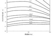
ところで、表2に示すように、LED電源装置4の入力コンデンサ33には1.60Aの実効電流が流れる。ここで、図4に、フィルムコンデンサの中でも比較的大電流を流せるメタライズドフィルムコンデンサ(日通工エレクトロニクス製、FPBシリーズ、DC650V)の許容実効電流値を示す。図4から分かるように、容量が0.15μFの場合、スイッチング周波数100kHzにおける許容実効電流値は1.2A程度であることから、1つの入力コンデンサ33の代わりに、容量が0.75μFの2つのコンデンサの並列回路を使用してディレーティングを確保する等の対策が必要となる。なお、LED電源装置1においては、入力コンデンサ31及び32に流れる電流の実効値は、許容実効電流値1.2A未満の1.13Aであり、ディレーティングが確保される。
By the way, as shown in Table 2, an effective current of 1.60 A flows through the
参照として、入力コンデンサ33に流れる電流がその許容実効電流値以下となるように入力コンデンサ33の容量を選定する場合、0.33μFの容量が必要となる。表3に、表2の測定条件から入力コンデンサ33の容量のみを0.15μFから0.33μFに変更した場合の電気特性を示す。
As a reference, when the capacitance of the
表3.LED電源装置4の電気特性
Table 3. Electrical characteristics of LED power supply 4
表3に示すように、入力コンデンサ33の容量を増加させたことにより、入力力率が低下し、特に高い電源電圧(200Vac、242Vac)において入力力率は99%未満となってしまうことが分かる。このように、入力コンデンサ33として1つのコンデンサを用いる構成では、高い入力力率とコンデンサのディレーティングを両立させるのが難しいことが分かる。
As shown in Table 3, it can be seen that the input power factor is decreased by increasing the capacitance of the
以上より、本実施形態のLED電源装置1によると、以下(1)乃至(4)の有利な効果が得られる。 From the above, according to the LED power supply device 1 of the present embodiment, the following advantageous effects (1) to (4) can be obtained.
(1)高周波電流の均等な分流
図1に戻り、DC/DCコンバータ40のスイッチングによる高周波電流の分流について再度説明すると、入力コンデンサ31が電源となる電源電圧半周期には、高周波電流は、入力コンデンサ31→トランス41の1次巻線N1→スイッチング素子42→ダイオードD4に流れる。一方、入力コンデンサ32が電源となる電源電圧半周期には、高周波電流は、入力コンデンサ32→トランス41の1次巻線N1→スイッチング素子42→ダイオードD2に流れる。このように、高周波電流は入力コンデンサ31及び32に時分割的に均等に分流される。このような時分割的に均等な分流は、入力コンデンサ31及び32の間の容量ばらつき、スイッチング素子42から入力コンデンサ31及び32までの経路のインピーダンスの差等に依存せず実現される。従って、本実施形態によるLED電源装置1は、高い入力力率を実現しつつも入力コンデンサ31及び32のディレーティングを確保し、入力コンデンサ31及び32に流れる電流を均等に分流して回路の正確な寿命設計を実現することを可能とする。
(1) Equal shunting of the high-frequency current Returning to FIG. 1, the shunting of the high-frequency current due to the switching of the DC /
(2)突入電流の均等な分流
交流電源ACの投入時の突入電流について、交流ラインLaが交流ラインLbに対して正側の場合には、突入電流は、交流ラインLa→ダイオードD1→入力コンデンサ31→交流ラインLbに流れる。一方、交流ラインLbが交流ラインLaに対して正側の場合には、突入電流は、交流ラインLb→ダイオードD3→入力コンデンサ32→交流ラインLaに流れる。従って、長期的な視点において、突入電流が入力コンデンサ31及び32の各々に流れ込む機会(確率)は1/2となる。このような突入電流の均等な分流も、入力コンデンサ31及び32の間の容量ばらつき等によらず実現される。
(2) Uniform shunting of inrush current When the AC line La is positive with respect to the AC line Lb with respect to the inrush current when the AC power supply AC is turned on, the inrush current is AC line La → diode D1 → input capacitor. 31 → Flows to the AC line Lb. On the other hand, when the AC line Lb is on the positive side with respect to the AC line La, the inrush current flows from the AC line Lb → the diode D3 → the
(3)シグナルグランドの設計容易性
低電位側の直流ラインL−は、主電流回路の基準電位(以下、「パワーグランド」という)となる一方で、制御回路45等の小信号回路の基準電位(以下、「シグナルグランド」という)が接続される。ここで、比較例のLED電源装置4(図10)において、全波整流器20の低電位側出力端T−からスイッチング素子42のソース端子(ソース端子に電流検出抵抗が接続される場合には電流検出抵抗の低電位側電極、以下同じ)までの直流ラインL−がパワーグランドとなる。ここで、低電位側出力端T−から入力コンデンサ33の低電位側電極までの配線には入力電流による低周波電流が主に流れる一方で、入力コンデンサ33の低電位側電極からスイッチング素子42のソース端子までの配線にはDC/DCコンバータ40のスイッチングによる高周波電流が主に流れる。このように、同じパワーグランドにおいても区間によって流れる電流が異なる。そのため、シグナルグランドとパワーグランドの接続点によっては、得られるシグナルグランドにおける電位の安定性、すなわち制御回路45等の制御の安定性が異なる。従って、比較例のLED電源装置4においては、シグナルグランドとパワーグランドの接続点を直流ラインL−のどのポイントとするかについての検討に時間と労力がかかる。
(3) Ease of design of signal ground The DC line L- on the low potential side serves as the reference potential of the main current circuit (hereinafter referred to as “power ground”), while the reference potential of the small signal circuit such as the
一方、本実施形態のLED電源装置1においては、低電位側の直流ラインL−に入力コンデンサが接続されないため、直流ラインL−には一様に電流が流れる。従って、シグナルグランド(図1のGs)が直流ラインL−のどのポイントに接続されても電位の安定性、すなわち制御回路45等の制御の安定性は同じである。このように、パワーグランドである直流ラインL−に入力コンデンサ31及び32が接続されないため、シグナルグランドに関する設計が容易となり、設計の省力化が可能となる。
On the other hand, in the LED power supply device 1 of the present embodiment, since no input capacitor is connected to the low potential side DC line L−, a current flows uniformly through the DC line L−. Therefore, the stability of the potential, that is, the control stability of the
(4)雷サージ耐性
LED電源装置1及び4の筐体(不図示)は接地される。ここで、コモンモード(交流電源と接地間)の雷サージが筐体に印加されて筐体と全波整流器20の高電位側出力端T+の間で絶縁破壊が起こったとする。この場合、比較例によるLED電源装置4においては、サージ電流が、高電位出力端T+→入力コンデンサ33→低電位出力端T−→全波整流器20のダイオードD2及びD4→交流ラインLa及びLbに流れ、全波整流器20が故障する可能性がある。一方、本実施形態によるLED電源装置1においては、サージ電流は、高電位出力端T+→入力コンデンサ31及び32→交流ラインLb及びLaに流れ、全波整流器20のいずれのダイオードも通過しない。従って、LED電源装置1においては、雷サージに対する耐性が増し、高い信頼性が得られる。
(4) Lightning surge resistance The housings (not shown) of the LED power supply devices 1 and 4 are grounded. Here, it is assumed that a lightning surge in common mode (between the AC power supply and the ground) is applied to the casing, and dielectric breakdown occurs between the casing and the high potential side output terminal T + of the full-
実施形態2.
上記実施形態1においては、2つの入力コンデンサに流れる電流を均等化して双方の寿命が均一化される構成を示したが、本実施形態においてはさらに、2つの入力コンデンサの温度条件が略同一となるようにして双方の寿命が均一化される構成を示す。これは、コンデンサの寿命は通電される電流だけでなく周囲温度にも依存することに基づく。
In the first embodiment, the configuration in which the currents flowing through the two input capacitors are equalized and the lifetimes of both are made uniform is shown. However, in this embodiment, the temperature conditions of the two input capacitors are substantially the same. In this way, a configuration in which both lifetimes are made uniform is shown. This is based on the fact that the lifetime of a capacitor depends not only on the energized current but also on the ambient temperature.
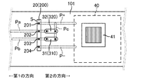
図5にLED電源装置1の要部の基板実装例を示す。なお、図は模式図であり、寸法通りではない。基板101上に、上述したフィルタ回路10(不図示)、全波整流器20、入力コンデンサ回路30及びDC/DCコンバータ40が実装される。DC/DCコンバータ40内のトランス41以外の素子及び配線は不図示であるが適宜実装されるものとする。LED電源装置1とLED2が別置される場合には、入力コンデンサ31及び32は主にトランス41及び全波整流器20からの輻射熱によって昇温される。LED電源装置1とLED2が一体化される場合には、入力コンデンサ31及び32は主にLED2、トランス41及び全波整流器20からの輻射熱によって昇温される。
FIG. 5 shows a substrate mounting example of the main part of the LED power supply device 1. In addition, a figure is a schematic diagram and is not as the dimension. On the
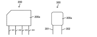
図6に、全波整流器20に使用される例示的なリード実装型のブリッジダイオード200(新電元製、D3SBA60)並びに入力コンデンサ31及び32に使用される例示的なフィルムコンデンサ300(日通工エレクトロニクス製、FPBシリーズ、DC650V、0.1〜0.15μF)の概略図を示す。図6に示すように、ブリッジダイオード200はそのボディ200aから同一方向に平行に延在する4本のリード201、202、203及び204を有する。内側のリード202及び203がそれぞれ入力端Ta及びTbに対応し、外側のリード201及び204がそれぞれ高電位側出力端T+及び低電位側出力T−に対応する。また、フィルムコンデンサ300は、ボディ300aから略同一方向に延在する2本のリード301及び302を有するディスクリート部品である。以降において、入力コンデンサ31及び32に対応するフィルムコンデンサをそれぞれフィルムコンデンサ310及び320というものとする。
FIG. 6 shows an exemplary lead-mounted bridge diode 200 (manufactured by Shindengen, D3SBA60) used for the full-
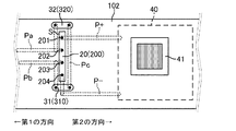
パターン間の絶縁距離を考慮しつつ効率的な配置で回路全体の部品を実装するために、図5に示すように、ブリッジダイオード200の交流ラインLa及びLbに対応する交流パターンPa及びPbと、直流ラインL+及びL−に対応する直流パターンP+及びP−とはブリッジダイオード200を挟んで反対方向に延在するように引き出される。なお、各パターンは基板101の上面視において背面側(すなわち、紙面裏側)に形成されているものとする。以降において、交流パターンPa及びPbが延在する方向を第1の方向とし、その反対方向を第2の方向というものとする。
In order to mount the components of the entire circuit in an efficient arrangement while considering the insulation distance between the patterns, as shown in FIG. 5, AC patterns Pa and Pb corresponding to the AC lines La and Lb of the
基板101の上面視において、フィルムコンデンサ310及び320は、ブリッジダイオード200と直流パターンP+及びP−で画定される領域において、フィルムコンデンサ310及び320の各長手方向がブリッジダイオード200の主面Sに対して垂直になるように配置される。フィルムコンデンサ310及び320は、効率的なパターン形成のため、好ましくは長手方向に端部を揃えて配置される。
In the top view of the
フィルムコンデンサ310及び320の各一端は接続パターンPcを介して直流パターンP+に接続される。フィルムコンデンサ310の他端は、交流パターンPbの第2の方向に突出して形成された部分に接続され、フィルムコンデンサ320の他端は、交流パターンPaの第2の方向に突出して形成された部分に接続される。これにより、フィルムコンデンサ310及び320が比較的短いパターンによって交流入力端Ta、交流入力端Tb及び高電位出力端T+に接続される。
One end of each of the
このような配置により、入力コンデンサ31及び32(フィルムコンデンサ310及び320)は、発熱部品であるトランス41及び全波整流器20(ブリッジダイオード200)から均等に輻射熱を受けることになる。従って、入力コンデンサ31及び32の寿命の均一性が高まる。
With such an arrangement, the
実施形態3.
実施形態2では、入力コンデンサの使用温度を均一化する構成を示したが、本実施形態ではさらに、入力コンデンサの使用温度を低い状態で均一化する構成を示す。
Embodiment 3. FIG.
In the second embodiment, the configuration in which the operating temperature of the input capacitor is made uniform is shown, but in this embodiment, the configuration in which the operating temperature of the input capacitor is made uniform in a low state is further shown.
図7にLED電源装置1の要部の基板実装例を示す。なお、図は模式図であり、寸法通りではない。基板102上に、上述したフィルタ回路10(不図示)、全波整流器20、入力コンデンサ回路30及びDC/DCコンバータ40が実装される。DC/DCコンバータ40内のトランス41以外の素子及び配線は不図示であるが適宜実装されているものとする。なお、全波整流器20並びに入力コンデンサ31及び32に使用される部品は実施形態2のものと同様であるものとし、第1の方向及び第2の方向の定義も実施形態2のものと同様であるものとする。
FIG. 7 shows a substrate mounting example of the main part of the LED power supply device 1. In addition, a figure is a schematic diagram and is not as the dimension. On the
図7に示すように、基板102の上面視において、フィルムコンデンサ310とフィルムコンデンサ320は、ブリッジダイオード200を挟んで対向する位置において、フィルムコンデンサ310及び320の各長手方向がブリッジダイオード200の長手方向に垂直となるように配置される。より具体的には、フィルムコンデンサ310がブリッジダイオード200のリード204の端部側に配置され、フィルムコンデンサ320がブリッジダイオード200のリード201の端部側に配置される。好ましくは、ダイオードブリッジ200の長手方向の中心軸がフィルムコンデンサ310及び320に交差するように、これらの部品が配置される。
As shown in FIG. 7, in the top view of the
フィルムコンデンサ310及び320の各一端は接続パターンPcを介して直流パターンP+に接続される。フィルムコンデンサ310の他端は交流パターンPbに接続され、フィルムコンデンサ320の他端は交流パターンPaに接続される。なお、直流パターンP−はフィルムコンデンサ310のリード間、すなわち、交流パターンPbと接続パターンPcの間に、両パターンに平行に形成される。これにより、ジャンパー線等を用いずに各パターンが形成される。
One end of each of the
このような配置により、実施形態2と同様に、入力コンデンサ31及び32(フィルムコンデンサ310及び320)は、発熱部品であるトランス41及び全波整流器20(ブリッジダイオード200)から均等に輻射熱を受けることになる。これにより、入力コンデンサ31及び32の寿命の均一性が得られる。またさらに、入力コンデンサ31及び32(フィルムコンデンサ310及び320)が、上記発熱部品(特にトランス41)から受ける輻射熱が軽減されるので、入力コンデンサ31及び32の長寿命化が可能となる。
With this arrangement, as in the second embodiment, the
実施形態4.
実施形態1では、入力コンデンサ31及び32の共通の一端が全波整流器20の高電位側出力端T+に接続される構成を示したが、本実施形態では、入力コンデンサ31及び32の共通の一端が全波整流器20の低電位側出力端T−に接続される構成を示す。
Embodiment 4 FIG.
In the first embodiment, a configuration in which one common end of the
図8に本実施形態に係るLED電源装置1を含むLED照明装置3の回路構成図を示す。入力コンデンサ回路30において、入力コンデンサ31は低電位側出力端T−と入力端Taの間に接続され、入力コンデンサ32は低電位側出力端T−と入力端Tbの間に接続される。入力コンデンサ31は、入力端Taが入力端Tbに対して正側となる場合にDC/DCコンバータ40の電源となる。具体的には、入力コンデンサ31は、交流ラインLa→入力コンデンサ31→ダイオードD4→交流ラインLbに電流が流れることにより充電され、入力コンデンサ31→ダイオードD1→直流ラインL+→DC/DCコンバータ40→直流ラインL−に電流が流れることにより放電される。一方、入力コンデンサ32は、入力端Tbが入力端Taに対して正側となる場合にDC/DCコンバータ40の電源となる。具体的には、入力コンデンサ32は、交流ラインLb→入力コンデンサ32→ダイオードD2→交流ラインLaに電流が流れることにより充電され、入力コンデンサ32→ダイオードD3→直流ラインL+→DC/DCコンバータ40→直流ラインL−に電流が流れることにより放電される。
FIG. 8 shows a circuit configuration diagram of the LED lighting device 3 including the LED power supply device 1 according to the present embodiment. In the
本実施形態の作用は実質的に図1の実施形態1のものと同様である。そして、本実施形態によると、実施形態1と同様に、上述した(1)高周波電流の均等な分流、及び(2)突入電流の均等な分流の効果が得られる。 The operation of this embodiment is substantially the same as that of Embodiment 1 of FIG. According to the present embodiment, as in the first embodiment, the effects of (1) equal shunting of the high-frequency current and (2) equal shunting of the inrush current can be obtained.
変形例.
以上に本発明の好適な実施形態を示したが、本発明は、例えば以下に示すように種々の態様に変形可能である。
Modified example.
Although preferred embodiments of the present invention have been described above, the present invention can be modified into various modes as shown below, for example.
例えば、上記実施形態においては、DC/DCコンバータ40として絶縁型フライバックコンバータを示したが、DC/DCコンバータ40は、例えば図9に示すような非絶縁型の降圧チョッパ回路であってもよい。図9において、DC/DCコンバータ40はコイル49、スイッチング素子42、ダイオード43、平滑コンデンサ44、制御回路45´、及び電流検出抵抗48を含む。図9に示すDC/DCコンバータ40では、スイッチング素子42のオン期間に、電流が入力部(全波整流器20の高電位出力端T+)→LED2(不図示)→コイル49→スイッチング素子42→グランド(低電位側出力端T−)に流れてコイル49にエネルギーが蓄積される。スイッチング素子42のオフ期間に、そのエネルギーをもとに電流がコイル49→ダイオード43→LED2(不図示)に流れる。LED電流はスイッチング素子42のPWM制御におけるオンデューティ(パルス幅)によって決まり、平滑コンデンサ44によって平滑化される。本変形例では、制御回路45´に誤差増幅器等が含まれ、電流検出抵抗48に発生する電圧が所定値で一定となるように、制御回路45´がスイッチング素子42をスイッチングする。これにより、DC/DCコンバータ40の出力が定電流制御される。
For example, in the above embodiment, an isolated flyback converter is shown as the DC /
また、上記実施形態及び変形例では、DC/DCコンバータ40において定電流制御が採用される構成を示したが、定電力制御が採用される構成としてもよい。例えば、DC/DCコンバータ40(平滑コンデンサ44)の出力電圧を検出する電圧検出回路(不図示)による電圧検出値と電流検出抵抗48による電流検出値とが乗算され、乗算値が設定値で一定となるように制御される構成としてもよい。これにより、LED電力がフィードバック制御される。また、DC/DCコンバータ40において、フィードバック制御ではなくフィードフォワード制御が採用されてもよい。この場合、PWM制御におけるパルス幅は制御回路45又は45´において決定され、図1の実施形態においてはフォトカプラ46、誤差増幅器47及び電流検出抵抗48が不要となり、図9の変形例においては電流検出抵抗48が不要となる。
In the embodiment and the modification, the configuration in which the constant current control is employed in the DC /
1 LED電源装置
2 LED
3 LED照明装置
20 全波整流器
30 入力コンデンサ回路
31、32 入力コンデンサ
40 DC/DCコンバータ
41 トランス
42 スイッチング素子
43 ダイオード
44 平滑コンデンサ
45、45´ 制御回路
101、102 基板
200 ブリッジダイオード
300、310、320 フィルムコンデンサ
Ta、Tb 入力端
T+ 高電位側出力端
T− 低電位側出力端
La、Lb 交流ライン
L+、L− 直流ライン
Pa、Pb 交流パターン
P+、P− 直流パターン
S 主面
1
3
Claims (6)
第1の入力端、第2の入力端、第1の出力端及び第2の出力端を有し、前記第1及び第2の入力端に交流電圧が入力される全波整流器と、
前記第1の入力端と前記第1の出力端との間に接続された第1の入力コンデンサ及び前記第2の入力端と前記第1の出力端との間に接続された第2の入力コンデンサを有し、前記第1の入力コンデンサ及び前記第2の入力コンデンサの容量が等しく、該容量は入力力率が99.0%以上となるように設定された入力コンデンサ回路と、
前記第1の入力コンデンサ及び前記第2の入力コンデンサの電圧をスイッチング、変圧、整流及び平滑化して直流電流をLEDに供給するように構成されたDC/DCコンバータと
を備え、
前記全波整流器がリード挿入型のブリッジダイオードからなり、前記第1及び第2の入力コンデンサがそれぞれ第1及び第2のフィルムコンデンサからなり、前記ブリッジダイオード、前記第1及び第2のフィルムコンデンサ並びに前記DC/DCコンバータの各素子が実装された基板において、
前記第1及び第2の入力端にそれぞれ接続される第1及び第2の交流パターンが前記ブリッジダイオードの主面に対して第1の方向に延在するように配線され、前記第1及び第2の出力端にそれぞれ接続される第1及び第2の直流パターンが前記主面に対して前記第1の方向とは逆の第2の方向に延在するように配線され、
前記基板の上面視において、前記ブリッジダイオードと前記第1及び第2の直流パターンで画定される領域において、前記第1のフィルムコンデンサの長手方向及び前記第2のフィルムコンデンサの長手方向が前記ブリッジダイオードの主面に対して垂直になるように前記第1及び第2のフィルムコンデンサが配置された、LED電源装置。 An LED power supply,
A full-wave rectifier having a first input terminal, a second input terminal, a first output terminal, and a second output terminal, and an AC voltage is input to the first and second input terminals;
A first input capacitor connected between the first input terminal and the first output terminal; and a second input connected between the second input terminal and the first output terminal. An input capacitor circuit having a capacitor, wherein the first input capacitor and the second input capacitor have the same capacitance, and the capacitance is set so that the input power factor is 99.0% or more;
Switching a voltage of said first input capacitor and the second input capacitors, transformers, Bei example and configured DC / DC converter as rectifier and smoothes supplying a direct current to LED,
The full-wave rectifier comprises a lead insertion type bridge diode, the first and second input capacitors comprise first and second film capacitors, respectively, the bridge diode, the first and second film capacitors, and In the substrate on which each element of the DC / DC converter is mounted,
First and second AC patterns connected to the first and second input terminals, respectively, are wired so as to extend in a first direction with respect to the main surface of the bridge diode, and the first and second The first and second direct current patterns connected to the two output ends are wired so as to extend in a second direction opposite to the first direction with respect to the main surface,
In a top view of the substrate, in the region defined by the bridge diode and the first and second DC patterns, the longitudinal direction of the first film capacitor and the longitudinal direction of the second film capacitor are the bridge diode. The LED power supply device , wherein the first and second film capacitors are arranged so as to be perpendicular to the main surface of the LED power supply.
第1の入力端、第2の入力端、第1の出力端及び第2の出力端を有し、前記第1及び第2の入力端に交流電圧が入力される全波整流器と、 A full-wave rectifier having a first input terminal, a second input terminal, a first output terminal, and a second output terminal, and an AC voltage is input to the first and second input terminals;
前記第1の入力端と前記第1の出力端との間に接続された第1の入力コンデンサ及び前記第2の入力端と前記第1の出力端との間に接続された第2の入力コンデンサを有し、前記第1の入力コンデンサ及び前記第2の入力コンデンサの容量が等しく、該容量は入力力率が99.0%以上となるように設定された入力コンデンサ回路と、 A first input capacitor connected between the first input terminal and the first output terminal; and a second input connected between the second input terminal and the first output terminal. An input capacitor circuit having a capacitor, wherein the first input capacitor and the second input capacitor have the same capacitance, and the capacitance is set so that the input power factor is 99.0% or more;
前記第1の入力コンデンサ及び前記第2の入力コンデンサの電圧をスイッチング、変圧、整流及び平滑化して直流電流をLEDに供給するように構成されたDC/DCコンバータと A DC / DC converter configured to switch, transform, rectify and smooth the voltage of the first input capacitor and the second input capacitor to supply a direct current to the LED;
を備え、With
前記全波整流器がリード挿入型のブリッジダイオードからなり、前記第1及び第2の入力コンデンサがそれぞれ第1及び第2のフィルムコンデンサからなり、前記ブリッジダイオード、前記第1及び第2のフィルムコンデンサ並びに前記DC/DCコンバータの各素子が実装された基板の上面視において、The full-wave rectifier comprises a lead insertion type bridge diode, the first and second input capacitors comprise first and second film capacitors, respectively, the bridge diode, the first and second film capacitors, and In top view of the substrate on which each element of the DC / DC converter is mounted,
前記ブリッジダイオードの長手方向を挟んで対向する位置において、前記第1のフィルムコンデンサの長手方向及び前記第2のフィルムコンデンサの長手方向が前記ブリッジダイオードの長手方向に垂直となるように前記第1及び第2のフィルムコンデンサが配置された、LED電源装置。The first and second film capacitors are arranged at opposite positions across the longitudinal direction of the bridge diode so that the longitudinal direction of the first film capacitor and the longitudinal direction of the second film capacitor are perpendicular to the longitudinal direction of the bridge diode. An LED power supply device in which a second film capacitor is disposed.
Priority Applications (1)
| Application Number | Priority Date | Filing Date | Title |
|---|---|---|---|
| JP2013254691A JP6263769B2 (en) | 2013-12-10 | 2013-12-10 | LED power supply device and LED lighting device |
Applications Claiming Priority (1)
| Application Number | Priority Date | Filing Date | Title |
|---|---|---|---|
| JP2013254691A JP6263769B2 (en) | 2013-12-10 | 2013-12-10 | LED power supply device and LED lighting device |
Publications (2)
| Publication Number | Publication Date |
|---|---|
| JP2015115127A JP2015115127A (en) | 2015-06-22 |
| JP6263769B2 true JP6263769B2 (en) | 2018-01-24 |
Family
ID=53528767
Family Applications (1)
| Application Number | Title | Priority Date | Filing Date |
|---|---|---|---|
| JP2013254691A Active JP6263769B2 (en) | 2013-12-10 | 2013-12-10 | LED power supply device and LED lighting device |
Country Status (1)
| Country | Link |
|---|---|
| JP (1) | JP6263769B2 (en) |
Families Citing this family (2)
| Publication number | Priority date | Publication date | Assignee | Title |
|---|---|---|---|---|
| KR101982111B1 (en) * | 2018-06-08 | 2019-05-24 | 홍정흠 | LED Lighting Apparatus |
| CN119341334A (en) * | 2023-07-20 | 2025-01-21 | 芜湖美的智能厨电制造有限公司 | Power supply circuits for gas equipment and gas equipment |
Family Cites Families (3)
| Publication number | Priority date | Publication date | Assignee | Title |
|---|---|---|---|---|
| DE10042141A1 (en) * | 2000-08-28 | 2002-03-14 | Patent Treuhand Ges Fuer Elektrische Gluehlampen Mbh | Rectifier circuit adapted for power factor correction |
| JP2011062043A (en) * | 2009-09-14 | 2011-03-24 | Sanken Electric Co Ltd | Power factor improving circuit and led luminaire using the same |
| JP5409316B2 (en) * | 2009-12-14 | 2014-02-05 | 三菱電機株式会社 | Surge suppression circuit and lighting device |
-
2013
- 2013-12-10 JP JP2013254691A patent/JP6263769B2/en active Active
Also Published As
| Publication number | Publication date |
|---|---|
| JP2015115127A (en) | 2015-06-22 |
Similar Documents
| Publication | Publication Date | Title |
|---|---|---|
| JP5067443B2 (en) | LED lighting device | |
| EP2458940A1 (en) | Power control methods and apparatus | |
| JP6403042B2 (en) | Power supply apparatus and lighting apparatus using the same | |
| US9265127B2 (en) | Luminaire | |
| White et al. | An average current modulation method for single-stage LED drivers with high power factor and zero low-frequency current ripple | |
| TW201301936A (en) | A cascade boost and inverting buck converter with independent control | |
| JP5761301B2 (en) | Lighting device and lighting apparatus | |
| CN102612224B (en) | A kind of MR16LED lamp drive circuit, driving method and apply its MR16LED lamp illuminating system | |
| US20150054408A1 (en) | Three-phase power supply and system of leds with three-phase power supply | |
| CN103687167B (en) | Lighting device | |
| CN105636315A (en) | Lighting device and lighting fixture using same | |
| KR20110136537A (en) | LED driving circuit and method for overvoltage protection and constant current driving | |
| JP6603763B2 (en) | Lighting system | |
| JP6263769B2 (en) | LED power supply device and LED lighting device | |
| JP5691495B2 (en) | LED driving power supply device and LED lighting device | |
| JP6070049B2 (en) | LED lighting device and LED lighting apparatus | |
| JP5300501B2 (en) | Lighting device and lighting apparatus | |
| JP2013116003A (en) | Lighting device | |
| JP3986462B2 (en) | High frequency heating device | |
| US20100270931A1 (en) | Apparatus and methods of operation of passive led lighting equipment | |
| CN103249204A (en) | Built-in drive power supply of LED fluorescent lamp | |
| JP2016115515A (en) | Dc power source for lighting and lighting apparatus | |
| JP5807172B2 (en) | Power supply apparatus and lighting apparatus using the same | |
| JP2019164922A (en) | Lighting device, and emergency luminaire | |
| TWM553090U (en) | Lighting system |
Legal Events
| Date | Code | Title | Description |
|---|---|---|---|
| A621 | Written request for application examination |
Free format text: JAPANESE INTERMEDIATE CODE: A621 Effective date: 20161018 |
|
| A977 | Report on retrieval |
Free format text: JAPANESE INTERMEDIATE CODE: A971007 Effective date: 20170719 |
|
| A131 | Notification of reasons for refusal |
Free format text: JAPANESE INTERMEDIATE CODE: A131 Effective date: 20170725 |
|
| A521 | Request for written amendment filed |
Free format text: JAPANESE INTERMEDIATE CODE: A523 Effective date: 20170727 |
|
| TRDD | Decision of grant or rejection written | ||
| A01 | Written decision to grant a patent or to grant a registration (utility model) |
Free format text: JAPANESE INTERMEDIATE CODE: A01 Effective date: 20171114 |
|
| A61 | First payment of annual fees (during grant procedure) |
Free format text: JAPANESE INTERMEDIATE CODE: A61 Effective date: 20171127 |
|
| R150 | Certificate of patent or registration of utility model |
Ref document number: 6263769 Country of ref document: JP Free format text: JAPANESE INTERMEDIATE CODE: R150 |
|
| S531 | Written request for registration of change of domicile |
Free format text: JAPANESE INTERMEDIATE CODE: R313531 |
|
| R371 | Transfer withdrawn |
Free format text: JAPANESE INTERMEDIATE CODE: R371 |
|
| S111 | Request for change of ownership or part of ownership |
Free format text: JAPANESE INTERMEDIATE CODE: R313111 |
|
| R350 | Written notification of registration of transfer |
Free format text: JAPANESE INTERMEDIATE CODE: R350 |
