JP6263747B2 - Image display device and method of manufacturing image display device - Google Patents
Image display device and method of manufacturing image display device Download PDFInfo
- Publication number
- JP6263747B2 JP6263747B2 JP2016509619A JP2016509619A JP6263747B2 JP 6263747 B2 JP6263747 B2 JP 6263747B2 JP 2016509619 A JP2016509619 A JP 2016509619A JP 2016509619 A JP2016509619 A JP 2016509619A JP 6263747 B2 JP6263747 B2 JP 6263747B2
- Authority
- JP
- Japan
- Prior art keywords
- frame member
- display panel
- bent piece
- front surface
- image display
- Prior art date
- Legal status (The legal status is an assumption and is not a legal conclusion. Google has not performed a legal analysis and makes no representation as to the accuracy of the status listed.)
- Active
Links
- 238000004519 manufacturing process Methods 0.000 title claims description 6
- 238000005401 electroluminescence Methods 0.000 claims description 35
- 238000005452 bending Methods 0.000 claims description 14
- 230000002093 peripheral effect Effects 0.000 claims description 14
- 238000000034 method Methods 0.000 claims description 6
- 230000000149 penetrating effect Effects 0.000 claims 2
- 230000004048 modification Effects 0.000 description 22
- 238000012986 modification Methods 0.000 description 22
- 239000010409 thin film Substances 0.000 description 16
- 239000010410 layer Substances 0.000 description 12
- 239000000758 substrate Substances 0.000 description 12
- 239000003990 capacitor Substances 0.000 description 6
- 230000000694 effects Effects 0.000 description 6
- 239000010408 film Substances 0.000 description 6
- 229910052751 metal Inorganic materials 0.000 description 6
- 239000002184 metal Substances 0.000 description 6
- 239000011521 glass Substances 0.000 description 5
- 238000012423 maintenance Methods 0.000 description 5
- 239000000428 dust Substances 0.000 description 4
- 239000004973 liquid crystal related substance Substances 0.000 description 4
- 238000005516 engineering process Methods 0.000 description 3
- 239000011159 matrix material Substances 0.000 description 3
- 230000008569 process Effects 0.000 description 3
- XEEYBQQBJWHFJM-UHFFFAOYSA-N Iron Chemical compound [Fe] XEEYBQQBJWHFJM-UHFFFAOYSA-N 0.000 description 2
- 238000007792 addition Methods 0.000 description 2
- 229910052782 aluminium Inorganic materials 0.000 description 2
- XAGFODPZIPBFFR-UHFFFAOYSA-N aluminium Chemical compound [Al] XAGFODPZIPBFFR-UHFFFAOYSA-N 0.000 description 2
- 238000010586 diagram Methods 0.000 description 2
- 238000004049 embossing Methods 0.000 description 2
- 230000006872 improvement Effects 0.000 description 2
- 239000011229 interlayer Substances 0.000 description 2
- 239000000463 material Substances 0.000 description 2
- 238000003825 pressing Methods 0.000 description 2
- 230000008439 repair process Effects 0.000 description 2
- 239000004065 semiconductor Substances 0.000 description 2
- 230000008859 change Effects 0.000 description 1
- 210000000078 claw Anatomy 0.000 description 1
- 239000003086 colorant Substances 0.000 description 1
- 238000002788 crimping Methods 0.000 description 1
- 230000017525 heat dissipation Effects 0.000 description 1
- 230000005525 hole transport Effects 0.000 description 1
- 229910052742 iron Inorganic materials 0.000 description 1
- 239000002346 layers by function Substances 0.000 description 1
- 238000000465 moulding Methods 0.000 description 1
- 239000011368 organic material Substances 0.000 description 1
- 230000001681 protective effect Effects 0.000 description 1
- 230000005855 radiation Effects 0.000 description 1
- 239000002994 raw material Substances 0.000 description 1
- 230000009467 reduction Effects 0.000 description 1
- 230000001105 regulatory effect Effects 0.000 description 1
- 239000011347 resin Substances 0.000 description 1
- 229920005989 resin Polymers 0.000 description 1
- 238000009751 slip forming Methods 0.000 description 1
- 230000005236 sound signal Effects 0.000 description 1
- 125000006850 spacer group Chemical group 0.000 description 1
- 238000006467 substitution reaction Methods 0.000 description 1
Images
Classifications
-
- H—ELECTRICITY
- H05—ELECTRIC TECHNIQUES NOT OTHERWISE PROVIDED FOR
- H05K—PRINTED CIRCUITS; CASINGS OR CONSTRUCTIONAL DETAILS OF ELECTRIC APPARATUS; MANUFACTURE OF ASSEMBLAGES OF ELECTRICAL COMPONENTS
- H05K5/00—Casings, cabinets or drawers for electric apparatus
- H05K5/0017—Casings, cabinets or drawers for electric apparatus with operator interface units
-
- G—PHYSICS
- G02—OPTICS
- G02F—OPTICAL DEVICES OR ARRANGEMENTS FOR THE CONTROL OF LIGHT BY MODIFICATION OF THE OPTICAL PROPERTIES OF THE MEDIA OF THE ELEMENTS INVOLVED THEREIN; NON-LINEAR OPTICS; FREQUENCY-CHANGING OF LIGHT; OPTICAL LOGIC ELEMENTS; OPTICAL ANALOGUE/DIGITAL CONVERTERS
- G02F1/00—Devices or arrangements for the control of the intensity, colour, phase, polarisation or direction of light arriving from an independent light source, e.g. switching, gating or modulating; Non-linear optics
- G02F1/01—Devices or arrangements for the control of the intensity, colour, phase, polarisation or direction of light arriving from an independent light source, e.g. switching, gating or modulating; Non-linear optics for the control of the intensity, phase, polarisation or colour
- G02F1/13—Devices or arrangements for the control of the intensity, colour, phase, polarisation or direction of light arriving from an independent light source, e.g. switching, gating or modulating; Non-linear optics for the control of the intensity, phase, polarisation or colour based on liquid crystals, e.g. single liquid crystal display cells
- G02F1/133—Constructional arrangements; Operation of liquid crystal cells; Circuit arrangements
- G02F1/1333—Constructional arrangements; Manufacturing methods
- G02F1/133308—Support structures for LCD panels, e.g. frames or bezels
-
- H—ELECTRICITY
- H05—ELECTRIC TECHNIQUES NOT OTHERWISE PROVIDED FOR
- H05K—PRINTED CIRCUITS; CASINGS OR CONSTRUCTIONAL DETAILS OF ELECTRIC APPARATUS; MANUFACTURE OF ASSEMBLAGES OF ELECTRICAL COMPONENTS
- H05K5/00—Casings, cabinets or drawers for electric apparatus
- H05K5/02—Details
- H05K5/0217—Mechanical details of casings
-
- H—ELECTRICITY
- H10—SEMICONDUCTOR DEVICES; ELECTRIC SOLID-STATE DEVICES NOT OTHERWISE PROVIDED FOR
- H10K—ORGANIC ELECTRIC SOLID-STATE DEVICES
- H10K50/00—Organic light-emitting devices
- H10K50/80—Constructional details
- H10K50/84—Passivation; Containers; Encapsulations
-
- H—ELECTRICITY
- H10—SEMICONDUCTOR DEVICES; ELECTRIC SOLID-STATE DEVICES NOT OTHERWISE PROVIDED FOR
- H10K—ORGANIC ELECTRIC SOLID-STATE DEVICES
- H10K2102/00—Constructional details relating to the organic devices covered by this subclass
- H10K2102/301—Details of OLEDs
- H10K2102/351—Thickness
Landscapes
- Physics & Mathematics (AREA)
- Nonlinear Science (AREA)
- Optics & Photonics (AREA)
- Engineering & Computer Science (AREA)
- Microelectronics & Electronic Packaging (AREA)
- Mathematical Physics (AREA)
- Chemical & Material Sciences (AREA)
- Crystallography & Structural Chemistry (AREA)
- General Physics & Mathematics (AREA)
- Devices For Indicating Variable Information By Combining Individual Elements (AREA)
- Electroluminescent Light Sources (AREA)
- Liquid Crystal (AREA)
Description
本開示は、有機EL(Electro Luminescence)ディスプレイパネル等の表示パネルを備える画像表示装置に関する。 The present disclosure relates to an image display device including a display panel such as an organic EL (Electro Luminescence) display panel.
テレビ等の画像表示装置は、液晶ディスプレイパネルまたは有機EL(Electro Luminescence)ディスプレイパネル等の表示パネルを備える。 An image display device such as a television includes a display panel such as a liquid crystal display panel or an organic EL (Electro Luminescence) display panel.
また、表示パネルの前面周縁には、例えば、エスカッションまたはベゼル等と呼ばれる枠部材が配置される。 In addition, a frame member called an escutcheon or a bezel is disposed on the front peripheral edge of the display panel.
特許文献1は、画像を表示するパネルと、パネルを前面に支持したシャーシと、シャーシの背面に固定された複数の回路基板と、これらを内部に納めるフロントカバーおよびバックカバーとを備える画像表示装置を開示する。このフロントカバーは、パネルの画像表示面の周囲を覆うエスカッションの役割も果たす。
また、当該画像表示装置では、パネルの高画質化に伴う温度上昇を、バックカバーに設けた通気孔からの自然対流を十分に活用して抑制する構造が採用されている。 In addition, the image display device employs a structure that suppresses the temperature rise accompanying the improvement in the image quality of the panel by fully utilizing natural convection from the vent hole provided in the back cover.
本開示は、従来よりも狭額縁化が可能な画像表示装置を提供する。 The present disclosure provides an image display device capable of a narrower frame than conventional ones.
本開示における画像表示装置は、前面に画像を表示する表示パネル、および、表示パネルの背面側に配置され、表示パネルを保持するシャーシを有する表示ユニットと、表示パネルの前面周縁の少なくとも一部に沿って配置される第一枠部材とを備え、第一枠部材は、表示パネルの前面に沿って配置される前面部と、前面部に接続された折曲片部であって、折り曲げられることで、前面部とは反対側の端部がシャーシの背面の側に配置された折曲片部とを有する。 An image display device according to the present disclosure includes a display panel that displays an image on the front surface, a display unit that is disposed on the back side of the display panel and has a chassis that holds the display panel, and at least part of the front periphery of the display panel. A first frame member disposed along the front surface portion, the front surface portion disposed along the front surface of the display panel, and a bent piece portion connected to the front surface portion, and bendable. And the edge part on the opposite side to a front part has the bending piece part arrange | positioned at the back side of a chassis.
本開示における画像表示装置は、従来よりも狭額縁化が可能である。従って、例えば、画像表示装置の前面視における、画像の表示領域の割合を大きくすることができる。 The image display device according to the present disclosure can have a narrower frame than the conventional one. Therefore, for example, the ratio of the image display area in the front view of the image display device can be increased.
本願発明者は、従来の画像表示装置に関し、以下の問題が生じることを見出した。 The inventor of the present application has found that the following problems occur with respect to a conventional image display device.
従来の画像表示装置では、ベゼル等と呼ばれる枠部材を表示パネルに取り付ける場合、例えば、枠部材に設けられた、表示パネルの外側に位置するエンボスと、表示パネルの背面のシャーシの端部に配置された取付部材とがねじによって締結される。 In a conventional image display device, when a frame member called a bezel or the like is attached to a display panel, for example, an embossing provided on the frame member and positioned outside the display panel and an end of the chassis on the back of the display panel are arranged. The attached mounting member is fastened with screws.
また、例えば、枠部材の外側面から、表示パネルの表示面(前面)に平行な方向に挿入されたねじによって、シャーシの端部に配置された取付部材に枠部材が固定される場合もある。 In addition, for example, the frame member may be fixed to the mounting member disposed at the end of the chassis by screws inserted from the outer surface of the frame member in a direction parallel to the display surface (front surface) of the display panel. .
いずれの場合も、表示パネルの外周に、エンボスまたはねじ等の、枠部材の表示パネルに対する位置固定のための要素が存在する。そのため、これらの要素の存在により、狭額縁化(狭ベゼル化)が困難である。 In any case, elements for fixing the position of the frame member with respect to the display panel, such as embossing or screws, exist on the outer periphery of the display panel. Therefore, it is difficult to narrow the frame (narrow bezel) due to the presence of these elements.
本開示は、このような知見に基づいてなされたものであり、本願発明者が鋭意検討した結果、狭額縁化が可能な画像表示装置の構造についての着想を得た。 The present disclosure has been made on the basis of such knowledge, and as a result of intensive studies by the inventor of the present application, the idea of the structure of an image display device capable of narrowing the frame was obtained.
以下、適宜図面を参照しながら実施の形態を説明する。但し、必要以上に詳細な説明は省略する場合がある。例えば、既によく知られた事項の詳細説明や実質的に同一の構成に対する重複説明を省略する場合がある。これは、以下の説明が不必要に冗長になるのを避け、当業者の理解を容易にするためである。 Hereinafter, embodiments will be described with reference to the drawings as appropriate. However, more detailed description than necessary may be omitted. For example, detailed descriptions of already well-known matters and repeated descriptions for substantially the same configuration may be omitted. This is to avoid the following description from becoming unnecessarily redundant and to facilitate understanding by those skilled in the art.
なお、本願発明者は、当業者が本開示を十分に理解するために添付図面および以下の説明を提供するのであって、これらによって請求の範囲に記載の主題を限定することを意図するものではない。 In addition, the inventor of the present application provides the accompanying drawings and the following description in order for those skilled in the art to fully understand the present disclosure, and is not intended to limit the subject matter described in the claims. Absent.
以下、図1〜図13を用いて実施の形態およびその変形例を説明する。まず、図1および図2を用いて、実施の形態における画像表示装置の構成概要について説明する。 Hereinafter, an embodiment and its modification will be described with reference to FIGS. First, the outline of the configuration of the image display apparatus according to the embodiment will be described with reference to FIGS. 1 and 2.
[1−1.画像表示装置の構成概要]
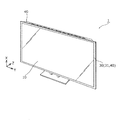
図1は、実施の形態における画像表示装置1の外観斜視図である。[1-1. Outline of image display device configuration]
FIG. 1 is an external perspective view of an
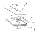
図2は、実施の形態における画像表示装置1の分解斜視図である。
FIG. 2 is an exploded perspective view of the
図1および図2に示すように、本実施の形態における画像表示装置1は、表示ユニット20と、第一枠部材31とを備える。
As shown in FIGS. 1 and 2, the
表示ユニット20は、前面に画像を表示する表示パネル10と、表示パネル10の背面側に配置され、表示パネル10を保持するシャーシ21とを有する。
The
本実施の形態では、表示パネル10として、有機ELディスプレイパネルが採用されている。有機ELディスプレイパネルは、2枚のガラス基板の間に有機EL素子が配置された構成を有する自発光型の表示パネルであり、液晶ディスプレイパネルのようなバックライトは不要である。そのため、例えば厚みが1mm〜3mm程度の薄型の有機ELディスプレイパネルを実現することができる。
In the present embodiment, an organic EL display panel is employed as the
第一枠部材31は、表示パネル10の前面周縁の少なくとも一部に沿って配置される部材である。つまり、第一枠部材31は、表示パネル10の前面周縁に配置される額縁として表示ユニット20に取り付けられる部材であり、例えば、アルミニウムなどの金属の板材を加工することで作製される。また、本実施の形態では、第一枠部材31と第二枠部材40とにより、表示ユニット20の周縁を保持する枠部材30が構成されている。
The
第一枠部材31は、表示パネル10の前面に沿って配置される前面部32と、前面部32に接続された折曲片部33であって、折り曲げられることで、前面部32とは反対側の端部がシャーシ21の背面の側に配置された折曲片部33とを有する。
The
本実施の形態では、第一枠部材31は、表示パネル10の前面周縁の全域に沿って配置された環状の部材であり、折曲片部33を複数有する。
In the present embodiment, the
より詳細には、第一枠部材31は、前面視において矩形の表示パネル10の4辺に沿って配置された角環状の部材である。また、第一枠部材31における、表示パネル10の4辺のそれぞれに対応する部分に少なくとも1つ(本実施の形態では2以上)の折曲片部33が配置されている。
More specifically, the
第二枠部材40は、折曲片部33が貫通するスリット(取付孔43)を有する。第一枠部材31が有する複数の折曲片部33のそれぞれは、第二枠部材40の取付孔43を貫通した状態で折り曲げられる。これにより、第一枠部材31が表示ユニット20に取り付けられる。
The
枠部材30(第一枠部材31および第二枠部材40)の詳細、および、枠部材30の表示ユニット20への取り付け構造等については、図6〜図9を用いて後述する。
Details of the frame member 30 (the
本実施の形態では、画像表示装置1はさらに、シャーシ21の背面に配置された複数の回路基板50、51、および、シャーシ21の背面を覆うように配置されたバックカバー60を備える。
In the present embodiment, the
複数の回路基板50のそれぞれは、表示パネル10に信号電圧を供給する駆動回路(ドライバ)が設けられた駆動回路基板である。複数の回路基板50は、シャーシ21の背面の周縁に沿うように配置されるとともに、フレキシブルケーブルを介して表示パネル10と接続される。
Each of the plurality of
また、シャーシ21の背面の中央部を含む所定の領域(中央部分)に複数の回路基板51が取り付けられている。これら回路基板51が有する電子回路は、受信した映像信号を処理する信号処理回路、走査駆動回路および信号線駆動回路の動作を制御する制御回路、および、電力を外部から受け取って各回路に供給する電源回路などである。
In addition, a plurality of
なお、画像表示装置1は、回路基板50と表示パネル10とを接続するフレキシブルケーブル等の、図2に図示していない他の要素も備えるが、本開示における画像表示装置1の特徴を明確に示すために、これら他の要素の図示および説明は省略する。
The
シャーシ21は、例えば金属製の部材であり、表示パネル10とは反対側に突出した凸部21aを有する。つまり、シャーシ21は、簡単に言うと、平板状の本体に凸部21aが形成された形状を有している。
The
本実施の形態におけるシャーシ21は、例えばアルミニウムまたは鉄からなる金属製の矩形状の板部材(金属板)を用いて、凸部21aが形成されるように当該板部材に絞り加工等のプレス加工を施すことによって成形された部材である。
The
また、シャーシ21の中央部分および周縁部等は、凸部21aが形成されていない領域であり、これら領域に回路基板50、51を配置することで、回路基板50、51の厚みが、画像表示装置1の厚みに与える影響が抑制されている。
Further, the central portion and the peripheral portion of the
このような構成を有する画像表示装置1は、例えば、受信した放送波等から得られる映像信号および音声信号を出力するテレビジョン受像機(テレビ)として実現される。
The
次に、以上のように構成された画像表示装置1が備える表示パネル10の基本的な構成について、図3〜図5を用いて説明する。
Next, a basic configuration of the
[1−2.表示パネル]
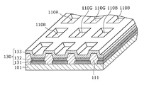
図3は、実施の形態における表示パネル10の一部切り欠き斜視図である。[1-2. Display panel]
FIG. 3 is a partially cutaway perspective view of the
図4は、実施の形態における表示パネル10のピクセルバンクの例を示す斜視図である。
FIG. 4 is a perspective view illustrating an example of a pixel bank of the
図3に示すように、表示パネル10は、複数個の薄膜トランジスタが配置されたTFT基板(TFTアレイ基板)101と、有機EL素子(発光部)130との積層構造により構成される。有機EL素子130は、下部電極である陽極131、有機材料からなる発光層であるEL層132および透明な上部電極である陰極133で構成される。
As shown in FIG. 3, the
なお、表示パネル10は、有機EL素子130の上方に配置されたガラス基板を有するが、ガラス基板の図示は、図3および図4では省略されている。
The
また、TFT基板101は、例えばガラス基板の上にゲート電極等の各種の要素が積層された構造を有している。つまり、表示パネル10は、全体として2枚のガラス基板に有機EL素子130等が挟まれた構造を有している。このような構造の表示パネル10の厚みは、例えば1mm〜3mm程度である。
The
TFT基板101には複数の画素110がマトリクス状に配置されており、各画素110には画素回路120が設けられている。
A plurality of
有機EL素子130は、複数の画素110のそれぞれに対応して形成されており、各画素110に設けられた画素回路120によって各有機EL素子130の発光の制御が行われる。有機EL素子130は、複数の薄膜トランジスタを覆うように形成された層間絶縁膜(平坦化膜)の上に形成される。
The
また、有機EL素子130は、陽極131と陰極133との間にEL層132が配置された構成となっている。陽極131とEL層132との間にはさらに正孔輸送層が積層形成され、EL層132と陰極133との間にはさらに電子輸送層が積層形成されている。なお、陽極131と陰極133との間には、その他の有機機能層が設けられていてもよい。
The
各画素110は、それぞれの画素回路120によって駆動制御される。また、TFT基板101には、画素110の行方向に沿って配置される複数のゲート配線(走査線)140と、ゲート配線140と交差するように画素110の列方向に沿って配置される複数のソース配線(信号配線)150と、ソース配線150と平行に配置される複数の電源配線(図3では省略)とが形成されている。各画素110は、例えば直交するゲート配線140とソース配線150とによって区画されている。
Each
ゲート配線140は、各画素回路120に含まれるスイッチング素子として動作する薄膜トランジスタのゲート電極と行毎に接続されている。ソース配線150は、各画素回路120に含まれるスイッチング素子として動作する薄膜トランジスタのソース電極と列毎に接続されている。電源配線は、各画素回路120に含まれる駆動素子として動作する薄膜トランジスタのドレイン電極と列毎に接続されている。
The
図4に示すように、表示パネル10の各画素110は、3色(赤色、緑色、青色)のサブ画素110R、110G、110Bによって構成されている。これらのサブ画素110R、110G、110Bは、表示面上に複数個マトリクス状に配列されるように形成されている。
As shown in FIG. 4, each
各サブ画素110R、110G、110Bは、バンク111によって互いに分離されている。バンク111は、ゲート配線140に平行に延びる突条と、ソース配線150に平行に延びる突条とが互いに交差するように、格子状に形成されている。そして、この突条で囲まれる部分(すなわち、バンク111の開口部)の各々とサブ画素110R、110G、110Bの各々とが一対一で対応している。なお、本実施の形態において、バンク111はピクセルバンクとしたが、ラインバンクとしても構わない。
The sub-pixels 110R, 110G, and 110B are separated from each other by the
陽極131は、TFT基板101上の層間絶縁膜(平坦化膜)上でかつバンク111の開口部内に、サブ画素110R、110G、110B毎に形成されている。同様に、EL層132は、陽極131上でかつバンク111の開口部内に、サブ画素110R、110G、110B毎に形成されている。透明な陰極133は、複数のバンク111上で、かつ全てのEL層132(全てのサブ画素110R、110G、110B)を覆うように、連続的に形成されている。
The
さらに、画素回路120は、各サブ画素110R、110G、110B毎に設けられており、各サブ画素110R、110G、110Bと、対応する画素回路120とは、コンタクトホールおよび中継電極によって電気的に接続されている。なお、サブ画素110R、110G、110Bは、EL層132の発光色が異なることを除いて同一の構成である。
Furthermore, the
ここで、画素110における画素回路120の回路構成について、図5を用いて説明する。図5は、実施の形態の表示パネル10における画素回路120の構成を示す電気回路図である。
Here, a circuit configuration of the
図5に示すように、画素回路120は、スイッチング素子として動作する薄膜トランジスタSwTrと、駆動素子として動作する薄膜トランジスタDrTrと、対応する画素110に表示するためのデータを記憶するキャパシタCとで構成される。本実施の形態において、薄膜トランジスタSwTrは、画素110を選択するためのスイッチングトランジスタであり、薄膜トランジスタDrTrは、有機EL素子130を駆動するための駆動トランジスタである。
As shown in FIG. 5, the
薄膜トランジスタSwTrは、ゲート配線140に接続されるゲート電極G1と、ソース配線150に接続されるソース電極S1と、キャパシタCおよび薄膜トランジスタDrTrのゲート電極G2に接続されるドレイン電極D1と、半導体膜(図示せず)とで構成される。この薄膜トランジスタSwTrに接続されたゲート配線140およびソース配線150に所定の電圧が印加されると、当該ソース配線150に印加された電圧がデータ電圧としてキャパシタCに保存される。
The thin film transistor SwTr includes a gate electrode G1 connected to the
薄膜トランジスタDrTrは、薄膜トランジスタSwTrのドレイン電極D1およびキャパシタCに接続されるゲート電極G2と、電源配線160およびキャパシタCに接続されるドレイン電極D2と、有機EL素子130の陽極131に接続されるソース電極S2と、半導体膜(図示せず)とで構成される。この薄膜トランジスタDrTrは、キャパシタCが保持しているデータ電圧に対応する電流を、電源配線160からソース電極S2を通じて有機EL素子130の陽極131に供給する。これにより、有機EL素子130では、陽極131から陰極133へと駆動電流が流れてEL層132が発光する。
The thin film transistor DrTr includes a gate electrode G2 connected to the drain electrode D1 of the thin film transistor SwTr and the capacitor C, a drain electrode D2 connected to the
なお、上記構成の表示パネル10では、ゲート配線140とソース配線150との交点に位置する画素110毎に表示制御を行うアクティブマトリクス方式が採用されている。これにより、各画素110(各サブ画素110R、110G、110B)の薄膜トランジスタSwTrおよびDrTrによって、対応する有機EL素子130が選択的に発光し、所望の画像が表示される。
Note that the
次に、実施の形態における枠部材30(第一枠部材31および第二枠部材40)の詳細および枠部材30の表示ユニット20への取り付け構造等について、図6〜図9を用いて説明する。
Next, details of the frame member 30 (
[1−3.枠部材]
図6は、実施の形態における画像表示装置1の一部の構造を示す第1の分解斜視図であり、図7は、同構造を示す第2の分解斜視図である。[1-3. Frame member]
FIG. 6 is a first exploded perspective view showing a part of the structure of the
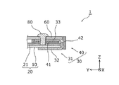
図8は、図7に対応する部分断面図であり、図9は、折曲片部33が折り曲げられ、かつ、バックカバー60が取り付けられた状態を示す部分断面図である。具体的には、図8および図9では、折曲片部33のX軸方向の中央位置における、YZ平面に平行な断面が図示されている。後述する図10および図11についても同じである。
FIG. 8 is a partial cross-sectional view corresponding to FIG. 7, and FIG. 9 is a partial cross-sectional view showing a state where the
なお、図6〜図9では、画像表示装置1における1つの折曲片部33の周辺の構造の概要を示すために、画像表示装置1の一部を切り取って図示している。また、以下では、1つの折曲片部33に着目し、当該折曲片部33の周辺の構造について説明するが、以下の内容は、複数の折曲片部33のそれぞれについても適用される。
6 to 9, a part of the
また、図6〜図9では、回路基板50等の図示は省略されている。このことは、後述する図10、図11、および図13でも同じである。
6 to 9, the
図6〜図9に示すように、第一枠部材31は、前面部32の端部から表示ユニット20の方向に突設された折曲片部33を有する。
As shown in FIGS. 6 to 9, the
第一枠部材31は、折曲片部33がシャーシ21の背面の方向に折り曲げられることで、表示ユニット20の端縁を挟む状態で表示ユニット20に配置される。
The
つまり、画像表示装置1の製造には、第一枠部材31の前面部32を、表示パネル10の前面に沿って配置する配置工程と、前面部32が表示パネル10の前面に沿って配置された状態で折曲片部33をシャーシ21の背面の方向に折り曲げる折曲工程とが含まれる。
That is, in the manufacture of the
具体的には、第一枠部材31の折曲片部33が、第二枠部材40の取付孔43に挿入され(図6〜図8参照)、その後、折曲片部33がシャーシ21の背面の方向に折り曲げられる(図9参照)。
Specifically, the
本実施の形態では、折曲片部33における前面部32に近い位置に、溝35および貫通孔36が形成されている。これにより、折曲片部33の折り曲げ位置が適切な位置に規制され、かつ、折り曲げ作業が容易化される。また、折曲片部33を折り曲げる際に生じる応力による前面部32の変形も抑制される。
In the present embodiment, the
なお、例えば、画像表示装置1の修理等のメンテナンスのために、折り曲げられた状態の折曲片部33が起された場合、折曲片部33の折り曲げ部分が脆弱になる場合または破断する場合などが想定される。この場合は、第一枠部材31は、新たな第一枠部材31と交換される。
For example, when the
第二枠部材40は、前面部32と対向する位置に配置された背面部41を有し、取付孔43は、背面部41に形成されている。また、背面部41には、取付孔43に挿入されて折り曲げられる折曲片部33を収容する凹部45が形成されている。
The
折り曲げられた状態の折曲片部33が凹部45に収容されることで背面部41の外面(バックカバー60側の面)における折曲片部33の出っ張りをなくすことが可能となる。
Since the
これにより、例えば、バックカバー60の周縁部と第二枠部材40との接触面積を増加させることができる。その結果、バックカバー60と第二枠部材40との間の隙間からの、塵または埃等の異物の侵入が抑制されるとともに、不要輻射低減の効果も期待できる。
Thereby, for example, the contact area between the peripheral portion of the
なお、本実施の形態では、折曲片部33は、折り曲げられた状態でシャーシ21にねじ止め(ねじ80によって締結)されている。具体的には、ねじ80が、バックカバー60のねじ孔64、折曲片部33のねじ孔34、および、第二枠部材40のねじ孔44を貫通した状態で、シャーシ21が有する、内面にねじ溝が形成されたねじ孔24と螺合する。
In the present embodiment, the
つまり、バックカバー60は、折曲片部33および第二枠部材40とともに、ねじ80によってシャーシ21と締結される。
That is, the
また、第二枠部材40はさらに、取付孔43の外側に配置され、折曲片部33の一部を覆うように設けられた側面部42を有する。
The
本実施の形態では、例えば図8に示すように、側面部42が、前面部32の外面(表示パネル10とは反対側の面)よりも外側(Z軸負の方向)に突出しない程度の幅(Z軸方向の長さ)に設けられている。これにより、画像表示装置1の外観を損なわずかつ、折曲片部33を隠すことができる。
In the present embodiment, for example, as shown in FIG. 8, the
なお、本実施の形態では、第一枠部材31は、表示パネル10の前面周縁の全域に沿って配置される環状の部材であり、複数の折曲片部33を有する。また、第二枠部材40は、これら複数の折曲片部33に対応する位置に取付孔43を有している。
In the present embodiment, the
従って、画像表示装置1の生産の際において、各折曲片部33の取付孔43への挿入の工程を同時に実行することが可能である。また、その後の各折曲片部33の折り曲げの工程も同時に実行することが可能である。
Therefore, in the production of the
[1−4.効果等]
以上のように、本実施の形態の画像表示装置1は、表示ユニット20と、第一枠部材31とを備える。表示ユニット20は、表示パネル10とシャーシ21とを有する。第一枠部材31は、表示パネル10の前面周縁に配置される前面部32と、前面部32に接続された折曲片部33とを有する。折曲片部33は、前面部32が表示パネル10の前面に沿った状態で、シャーシ21の背面の方向に折り曲げられる。[1-4. Effect]
As described above, the
つまり、本実施の形態の画像表示装置1では、前面部32から背方(Z軸正の方向、例えば図6参照)に延設された薄板状の部材(折曲片部33)を折り曲げることで、表示パネル10の額縁として機能する第一枠部材31を表示パネル10に取り付けることができる。従って、ねじまたはボス等の要素を、表示パネル10の外周に配置することが不要である。
That is, in the
これにより、第一枠部材31の幅(例えば図6におけるY軸方向の長さ)を短くすることが可能である。すなわち、画像表示装置1によれば、狭額縁化が従来よりも容易となる。
Thereby, the width of the first frame member 31 (for example, the length in the Y-axis direction in FIG. 6) can be shortened. That is, according to the
その結果、例えば、第一枠部材31を、表示パネル10の周縁の保護部材として機能させつつ、視聴の妨げとなる額縁領域を従来よりも小さくすること(画像表示装置1の前面視における、画像の表示領域の割合を大きくすること)が可能である。
As a result, for example, while the
また、前面部32を、直接またはスペーサ等を介して表示パネル10の前面に当接させた状態で、折曲片部33を折り曲げることができる。つまり、前面部32と表示パネル10の前面との間の隙間を発生させないように、第一枠部材31を表示パネル10に取り付けることができる。
Further, the
これにより、例えば、前面部32と表示パネル10の前面との間の隙間からの異物の侵入が抑制される。また、例えば、前面部32と表示パネル10の前面との直接的または間接的な密着度が向上するため、表示パネル10から第一枠部材31への熱伝導の効率が向上する。その結果、表示パネル10で発生する熱についての第一枠部材31による放熱効果も向上する。
Thereby, for example, intrusion of foreign matter from a gap between the
なお、本実施の形態では、表示パネル10として有機ELディスプレイパネルが採用されている。そのため、折曲片部33が折り曲げられること(かしめられること)で、前面部32が表示パネル10の表示面(前面)を押圧する状態が生じた場合であっても、例えば液晶ディスプレイパネルと比べると、その押圧力が表示画質に及ぼす影響は小さい。
In the present embodiment, an organic EL display panel is employed as the
また、本実施の形態の画像表示装置1はさらに、第二枠部材40を備え、第二枠部材40は、表示ユニット20を挟んで前面部32と対向する位置に配置された背面部41を有する。第一枠部材31の折曲片部33は、第二枠部材40に形成された取付孔43を貫通した状態で折り曲げられている。
The
つまり、表示ユニット20の周縁部は、前後から第一枠部材31と第二枠部材40とで挟まれた状態で安定的に保持される。また、この保持には、折曲片部33が折り曲げられることによるかしめ力を利用することができるため、安定的な保持が容易に実現可能である。
That is, the peripheral edge of the
また、本実施の形態において、取付孔43は背面部41に形成されており、第二枠部材40はさらに、取付孔43の外側に配置され、折曲片部33の少なくとも一部を覆うように設けられた側面部42を有する。
In the present embodiment, the
つまり、第二枠部材40を、表示ユニット20の保持のための構造体として機能させるとともに、折曲片部33を隠す部材として機能させることができる。また、側面部42は、例えば表示パネル10の側方からの、画像表示装置1の内部への塵または埃等の異物の侵入を抑制する効果も生じさせることができる。
That is, the
また、本実施の形態において、折曲片部33は、折り曲げられた状態で、ねじ80によってシャーシ21と締結されている。
In the present embodiment, the
これにより、第一枠部材31の表示ユニット20に対する確実な固定が容易に実現される。
Thereby, reliable fixation with respect to the
また、本実施の形態の画像表示装置1はさらに、シャーシ21の背面を覆うように配置されたバックカバー60を備え、バックカバー60は、折曲片部33とともに、ねじ80によってシャーシ21と締結されている。
Further, the
このように、1つのねじ80に、バックカバー60の表示ユニット20への固定と、枠部材30(第一枠部材31および第二枠部材40)の表示ユニット20への固定とを担わせることで、画像表示装置1の部品点数が削減される。
In this way, one
また、本実施の形態では、表示ユニット20の周縁部を覆う枠部材30は、上述のように、表示ユニット20を前後から挟むようにして表示ユニット20に取り付けられる第一枠部材31と第二枠部材40とで構成されている。
Moreover, in this Embodiment, the
そのため、第一枠部材31を、表示パネル10の前面周縁の全域に沿って配置された環状の部材として構成することができる。より具体的には、本実施の形態では、表示パネル10は前面視において矩形であり、第一枠部材31は表示パネル10の4辺に沿って配置された角環状の部材である。また、折曲片部33は、第一枠部材31における4辺のそれぞれに対応する部分に少なくとも1つ配置されている。
Therefore, the
このように、第一枠部材31は、複数の部材の組み合わせによって構成する必要はなく、単一の部材として実現可能である。これにより、例えば、画像表示装置1の生産効率の向上または部品管理の簡素化等の効果が奏される。
Thus, the
また、第二枠部材40も同様に、複数の部材の組み合わせではなく単一の部材として実現することができる。
Similarly, the
なお、画像表示装置1における第一枠部材31または第二枠部材40に関する構造として、図6〜図9に示す構造以外の構造が採用されてもよい。
In addition, as a structure regarding the
そこで、画像表示装置1が採用可能な、第一枠部材31または第二枠部材40の構造に関する各種の変形例について、上記実施の形態との差分を中心に以下に説明する。
Therefore, various modifications relating to the structure of the
[2−1.変形例1]
図10は、実施の形態の変形例1における第一枠部材31の取り付け構造を示す部分断面図である。[2-1. Modification 1]
FIG. 10 is a partial cross-sectional view showing the attachment structure of the
図10に示す変形例1における画像表示装置1は、上記実施の形態とは異なり、第二枠部材40を備えていない。
Unlike the above-described embodiment, the
つまり、第一枠部材31の折曲片部33は、第二枠部材40を介さずに、ねじ80によって表示ユニット20(シャーシ21)と締結されている。
That is, the
この場合であっても、表示パネル10の額縁を構成する第一枠部材31の表示パネル10への取り付けは可能である。
Even in this case, the
なお、この場合、例えば図10に示すように、バックカバー60が、折曲片部33を隠す側面部61を有してもよい。つまり、画像表示装置1は、シャーシ21の背面、および、第一枠部材31の折曲片部33を覆うように配置されたバックカバー60を備えてもよい。
In this case, for example, as shown in FIG. 10, the
また、図10では、折曲片部33はシャーシ21に接触していない状態で、ねじ80によってシャーシ21と締結されているが、折曲片部33をシャーシ21に接触させた状態で折曲片部33とシャーシ21とがねじ80により締結されていてもよい。例えば、折曲片部33の一部を突出させ、当該一部がシャーシ21と当接するように折曲片部33を折り曲げ、この状態でねじ80によりシャーシ21に固定してもよい。
In FIG. 10, the
また、折曲片部33とシャーシ21との間に、例えば耐熱ゴムシート等の可撓性を有する部材を挟んで折曲片部33を折り曲げ、この状態でねじ80によりシャーシ21に固定してもよい。
Further, the
このように、折曲片部33を、シャーシ21の背面に直接的または間接的に接触させてねじ止めすることで、第一枠部材31のシャーシ21(表示ユニット20)に対する固定の安定性が向上する。
In this way, by fixing the
[2−2.変形例2]
図11は、実施の形態の変形例2における第一枠部材31の取り付け構造を示す部分断面図である。[2-2. Modification 2]
FIG. 11 is a partial cross-sectional view showing the attachment structure of the
図11に示す変形例2における画像表示装置1では、上記実施の形態とは異なり、バックカバー60は、ねじ80によって、シャーシ21と締結されていない。
In the
具体的には、バックカバー60は、ねじ80の頭部の外径よりも大きな内径を有するねじ孔64aを有する。これにより、ねじ80がシャーシ21のねじ孔24(例えば図8参照)に螺合する場合、ねじ80の頭部が、ねじ孔64aに収容される。つまり、ねじ80は、頭部が折曲片部33に直接的に当接した状態で、折曲片部33および背面部41(第二枠部材40)とシャーシ21とを締結する。
Specifically, the
この場合、バックカバー60は、例えばバックカバー60を固定するためのねじ等によってシャーシ21と締結されてもよい。また、例えば第二枠部材40の側面部42に設けられた孔または窪みと係合する爪をバックカバー60に備えることで、バックカバー60を表示ユニット20に取り付けてもよい。
In this case, the
このように、ねじ80の頭部を収容可能な大きさのねじ孔64aをバックカバー60に設けることで、バックカバー60からのねじ80の頭部の突出量を抑制することができる。
As described above, by providing the
[2−3.変形例3]
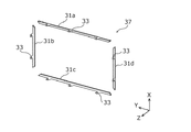
図12は、実施の形態の変形例3における第一枠部材37の構成例を示す斜視図である。[2-3. Modification 3]
FIG. 12 is a perspective view illustrating a configuration example of the
図12に示す変形例3における第一枠部材37は、上記実施の形態の第一枠部材31とは異なり、複数の部材の組み合わせによって構成されている。
Unlike the
具体的には、表示パネル10(例えば図2参照)の2つの長辺に沿って配置される第一枠部材31aおよび31c、ならびに、表示パネル10の2つの短辺に沿って配置される第一枠部材31bおよび31dによって、第一枠部材37が構成される。つまり、4つの部分的な部材(第一枠部材31a〜31d)によって、表示パネル10の前面周縁の全域に沿って配置された環状の部材である第一枠部材37が構成されている。
Specifically, the
なお、この場合、第一枠部材31aおよび31cは、図12におけるY軸に平行な線対称の構造である。そのため、一種類の部品を2N個(Nは1以上の整数)作製することで、第一枠部材31aおよび31cのそれぞれをN個得ることができる。
In this case, the
また、第一枠部材31bおよび31dについても同様であり、図12におけるX軸に平行な線対称の構造である。そのため、一種類の部品を2N個作製することで、第一枠部材31bおよび31dのそれぞれをN個得ることができる。
The same applies to the
なお、本変形例では、第一枠部材37は4つの部材(第一枠部材31a〜31d)で構成されているが、第一枠部材37を構成する部材の総数に特に限定はない。
In the present modification, the
このように、表示パネル10の前面周縁の全域を覆う第一枠部材37を、複数の部材(第一枠部材31a〜31d)で構成することで、例えば、部品としての第一枠部材37の取り扱いが容易化される。
Thus, the
また、例えば、上述のように、画像表示装置1の修理等のメンテナンス時において、折り曲げられた状態の折曲片部33を起すことで、折曲片部33の折り曲げ部分が脆弱になった場合または破断した場合を想定する。この場合、当該折曲片部33を有する第一枠部材31a〜31dのいずれかのみを、新たな部材と交換すればよい。このことは、例えば、画像表示装置1のメンテナンスに係るコストの抑制に寄与する。
Further, for example, as described above, when the
[2−4.変形例4]
図13は、実施の形態の変形例4における画像表示装置1の一部の構造を示す分解斜視図である。[2-4. Modification 4]
FIG. 13 is an exploded perspective view illustrating a partial structure of the
図13に示す変形例4における第一枠部材39は、上記実施の形態の第一枠部材31と同じく折曲片部33を有し、折曲片部33は、折り曲げられることで、前面部32とは反対側の端部がシャーシ21の背面の側に配置される。
The
しかし、第一枠部材39は、上記実施の形態の第一枠部材31とは異なり、表示ユニット20の端面に沿って配置される側面部38を有する。
However, unlike the
また、本変形例における第二枠部材40が有する側面部42aは、上記実施の形態における第二枠部材40が有する側面部42(例えば、図6参照)とは異なり、表示ユニット20の側方に延びる部分を有しない。
In addition, the
つまり、本変形例では、第一枠部材39の側面部38と、第二枠部材40の側面部42aとにより、表示ユニット20の外周を覆う側面が形成されている。
That is, in this modification, the side surface covering the outer periphery of the
なお、この場合、例えば、側面部38と第二枠部材40との間に隙間が生じないように、側面部38と第二枠部材40との間に、ゴム等の可撓性を有する部材を配置してもよい。
In this case, for example, a member having flexibility such as rubber between the
また、第二枠部材40は、側面部42aを有しなくてもよい。この場合、例えば、バックカバー60が、側面部61(図10参照)を有していれば、側面部61によって、折曲片部33および、第一枠部材39と第二枠部材40との境界部分を隠すことができる。
Moreover, the
また、第二枠部材40は、側面部42aに代えて実施の形態における側面部42を有してもよい。この場合、側面部42によって、折曲片部33の折れ曲がった部分(根元部分)を完全に隠すことができる。また、表示ユニット20の端面が、第一枠部材31の側面部38と、第二枠部材40の側面部42とによって二重に覆われるため、例えば、第一枠部材31と第二枠部材40との隙間からの異物の侵入の抑制がより確実化される。
Moreover, the
ここで、第一枠部材39の前面部32と側面部38とは、例えば金属製の一枚の板材に対するプレス加工によって形成されており、側面部38は、前面部32の長尺方向に沿って設けられたリブとして機能する。
Here, the
つまり、第一枠部材39が側面部38を有することで、第一枠部材39の強度が向上し、その結果、画像表示装置1の強度も向上する。
That is, since the
[3.他の実施の形態]
以上のように、本出願において開示する技術の例示として、実施の形態および変形例を説明した。しかしながら、本開示における技術は、これらに限定されず、適宜、変更、置き換え、付加、省略などを行った実施の形態にも適用可能である。また、上記実施の形態および変形例で説明した各構成要素を組み合わせて、新たな実施の形態とすることも可能である。そこで、以下、他の実施の形態を例示する。[3. Other Embodiments]
As described above, the embodiments and the modification examples have been described as examples of the technology disclosed in the present application. However, the technology in the present disclosure is not limited to these, and can also be applied to embodiments in which changes, replacements, additions, omissions, and the like are appropriately performed. Moreover, it is also possible to combine each component demonstrated by the said embodiment and modification, and can be set as a new embodiment. Therefore, other embodiments will be exemplified below.
例えば、実施の形態における第一枠部材31は、前面部32と折曲片部33とを一体に有しているが、前面部32と折曲片部33とが別体であってもよい。
For example, the
例えば樹脂を素材とする前面部32と、前面部32に取り付けられた、金属製の折曲片部33とによって、第一枠部材31が構成されてもよい。この場合、前面部32と折曲片部33とはインサート成形によって接合されてもよい。
For example, the
また、例えば、バックカバー60は、第二枠部材40の側面部42(図9参照)を外側から覆う側面部61(図10参照)を有してもよい。
Further, for example, the
また、画像表示装置1が備える表示パネル10の種類は、有機ELディスプレイパネルに限定されない。例えば、液晶ディスプレイパネル、または、プラズマディスプレイパネルなどが、表示パネル10として採用されてもよい。
Further, the type of the
いずれの場合であっても、折曲片部33を有する第一枠部材31(37、39)を取り付けることによる狭額縁化を実現することができる。
In any case, it is possible to realize a narrow frame by attaching the first frame member 31 (37, 39) having the
また、第一枠部材31の表示ユニット20への取り付けにねじ80を用いなくてもよい。本実施の形態のように第一枠部材31が環状の部材である場合、表示ユニット20の周囲に配置された複数の折曲片部33が、シャーシ21の背面の方向に折り曲げられることで、第一枠部材31を表示ユニット20に対して実質的に固定することも可能である。
Further, the
以上のように、本開示における技術の例示として、実施の形態を説明した。そのために、添付図面および詳細な説明を提供した。 As described above, the embodiments have been described as examples of the technology in the present disclosure. For this purpose, the accompanying drawings and detailed description are provided.
したがって、添付図面および詳細な説明に記載された構成要素の中には、課題解決のために必須な構成要素だけでなく、上記技術を例示するために、課題解決のためには必須でない構成要素も含まれ得る。そのため、それらの必須ではない構成要素が添付図面や詳細な説明に記載されていることをもって、直ちに、それらの必須ではない構成要素が必須であるとの認定をするべきではない。 Accordingly, among the components described in the accompanying drawings and the detailed description, not only the components essential for solving the problem, but also the components not essential for solving the problem in order to illustrate the above technique. May also be included. Therefore, it should not be immediately recognized that these non-essential components are essential as those non-essential components are described in the accompanying drawings and detailed description.
また、上述の実施の形態は、本開示における技術を例示するためのものであるから、請求の範囲またはその均等の範囲において種々の変更、置き換え、付加、省略などを行うことができる。 Moreover, since the above-mentioned embodiment is for demonstrating the technique in this indication, a various change, substitution, addition, abbreviation, etc. can be performed in a claim or its equivalent range.
本開示は、例えば狭額縁化が要求される画像表示装置に有用であり、テレビジョン受像機、モニタディスプレイ、デジタルサイネージ、携帯端末、タブレット端末、または、テーブル型表示装置等の画像表示装置として利用できる。 The present disclosure is useful for, for example, an image display device that requires a narrow frame, and is used as an image display device such as a television receiver, a monitor display, a digital signage, a portable terminal, a tablet terminal, or a table-type display device. it can.
1 画像表示装置
10 表示パネル
20 表示ユニット
21 シャーシ
21a 凸部
24、34、44、64、64a ねじ孔
30 枠部材
31、31a、31b、31c、31d、37、39 第一枠部材
32 前面部
33 折曲片部
35 溝
36 貫通孔
38、42、42a、61 側面部
40 第二枠部材
41 背面部
43 取付孔
45 凹部
50、51 回路基板
60 バックカバー
101 TFT基板
110 画素
110B、110G、110R サブ画素
111 バンク
120 画素回路
130 有機EL素子
131 陽極
132 EL層
133 陰極
140 ゲート配線
150 ソース配線
160 電源配線DESCRIPTION OF
Claims (9)
前記表示パネルの前面周縁の少なくとも一部に沿って配置される第一枠部材とを備え、
前記第一枠部材は、前記表示パネルの前面に沿って配置される前面部と、前記前面部に接続された折曲片部であって、折り曲げられることで、前記前面部とは反対側の端部が前記シャーシの背面の側に配置された折曲片部とを有し、
さらに、前記表示ユニットを挟んで前記第一枠部材の前記前面部と対向する位置に配置された背面部を有する第二枠部材を備え、
前記第一枠部材の前記折曲片部は、前記第二枠部材に形成された取付孔を貫通した状態で折り曲げられている
画像表示装置。 A display panel that displays an image on the front surface, and a display unit that is disposed on the back side of the display panel and has a chassis that holds the display panel;
A first frame member disposed along at least a part of the front peripheral edge of the display panel,
The first frame member is a front surface portion disposed along the front surface of the display panel, and a bent piece portion connected to the front surface portion, and is bent so as to be opposite to the front surface portion. end possess a bent piece portion arranged on the side of the rear of the chassis,
Furthermore, a second frame member having a back surface portion disposed at a position facing the front surface portion of the first frame member across the display unit,
The image display device , wherein the bent piece portion of the first frame member is bent in a state of penetrating an attachment hole formed in the second frame member .
前記第二枠部材はさらに、前記取付孔の外側に配置され、前記折曲片部の少なくとも一部を覆うように設けられた側面部を有する
請求項1記載の画像表示装置。 The mounting hole is formed in the back portion,
It said second frame member further wherein disposed on the outside of the mounting hole, the image display apparatus of claim 1 further comprising a side portion provided so as to cover at least a part of the bent piece.
請求項1または2に記載の画像表示装置。 The bent piece is a folded state, the image display apparatus according to claim 1 or 2 is fastened to the chassis by a screw.
前記バックカバーは、前記折曲片部とともに、前記ねじによって前記シャーシと締結されている
請求項3記載の画像表示装置。 And a back cover arranged to cover the back surface of the chassis,
The image display device according to claim 3 , wherein the back cover is fastened to the chassis together with the bent piece portion by the screw.
請求項1〜4のいずれか1項に記載の画像表示装置。 Said first frame member is an annular member disposed along the entire front peripheral edge of the display panel, the image display according to any one of claims 1 to 4, more chromatic the bent piece portion apparatus.
前記第一枠部材は前記表示パネルの4辺に沿って配置された角環状の部材であり、
前記折曲片部は、前記第一枠部材における前記4辺のそれぞれに対応する部分に少なくとも1つ配置されている
請求項5記載の画像表示装置。 The display panel is rectangular in front view,
The first frame member is an annular member disposed along the four sides of the display panel,
The image display device according to claim 5 , wherein at least one bent piece portion is disposed in a portion corresponding to each of the four sides of the first frame member.
請求項1〜3のいずれか1項に記載の画像表示装置。 Further, the rear of the chassis, and an image display apparatus according to any one of claims 1 to 3 having the first frame the back cover disposed so as to cover the bent piece portion of the member.
請求項1〜7のいずれか1項に記載の画像表示装置。 The display panel, the image display apparatus according to any one of claims 1 to 7, which is an organic EL (Electro Luminescence) display panel.
前記画像表示装置は、
前面に画像を表示する表示パネル、および、前記表示パネルの背面側に配置され、前記表示パネルを保持するシャーシを有する表示ユニットと、前記表示パネルの前面周縁の少なくとも一部に沿って配置される第一枠部材と、
前記表示ユニットを挟んで前記第一枠部材の前記前面部と対向する位置に配置された背面部を有する第二枠部材とを備え、
前記第一枠部材は、前面部と前記前面部に接続された折曲片部とを有し、
前記製造方法は、
前記前面部を、前記表示パネルの前面に沿って配置する配置工程と、
前記前面部が前記表示パネルの前面に沿って配置された状態で、前記折曲片部を前記シャーシの背面の方向に折り曲げる折曲工程とを含み、
前記折曲工程では、前記折曲片部は、前記第二枠部材に形成された取付孔を貫通した状態で折り曲げられる
画像表示装置の製造方法。 A method for manufacturing an image display device, comprising:
The image display device includes:
A display panel that displays an image on the front surface, a display unit that is disposed on the back side of the display panel and that has a chassis that holds the display panel, and is disposed along at least a portion of the front periphery of the display panel A first frame member ;
A second frame member having a back surface portion disposed at a position facing the front surface portion of the first frame member across the display unit ;
The first frame member has a front surface portion and a bent piece portion connected to the front surface portion,
The manufacturing method includes:
An arrangement step of arranging the front portion along the front surface of the display panel;
A bending step of bending the bent piece portion toward the rear surface of the chassis in a state where the front surface portion is disposed along the front surface of the display panel ;
In the bending step, the bent piece portion is bent in a state of penetrating an attachment hole formed in the second frame member .
Applications Claiming Priority (3)
| Application Number | Priority Date | Filing Date | Title |
|---|---|---|---|
| JP2014064664 | 2014-03-26 | ||
| JP2014064664 | 2014-03-26 | ||
| PCT/JP2014/006361 WO2015145510A1 (en) | 2014-03-26 | 2014-12-22 | Image display apparatus and image display apparatus manufacturing method |
Publications (2)
| Publication Number | Publication Date |
|---|---|
| JPWO2015145510A1 JPWO2015145510A1 (en) | 2017-04-13 |
| JP6263747B2 true JP6263747B2 (en) | 2018-01-24 |
Family
ID=54194112
Family Applications (1)
| Application Number | Title | Priority Date | Filing Date |
|---|---|---|---|
| JP2016509619A Active JP6263747B2 (en) | 2014-03-26 | 2014-12-22 | Image display device and method of manufacturing image display device |
Country Status (3)
| Country | Link |
|---|---|
| US (1) | US10098244B2 (en) |
| JP (1) | JP6263747B2 (en) |
| WO (1) | WO2015145510A1 (en) |
Families Citing this family (5)
| Publication number | Priority date | Publication date | Assignee | Title |
|---|---|---|---|---|
| CN104820305B (en) * | 2015-05-19 | 2018-12-11 | 深圳市华星光电技术有限公司 | Display device |
| KR102357930B1 (en) * | 2017-08-30 | 2022-02-03 | 엘지디스플레이 주식회사 | Display device |
| JP6585685B2 (en) * | 2017-10-31 | 2019-10-02 | ファナック株式会社 | Control unit with display |
| WO2020103143A1 (en) * | 2018-11-23 | 2020-05-28 | 深圳市光祥科技股份有限公司 | Led display unit |
| JP7399591B2 (en) * | 2021-10-11 | 2023-12-18 | 矢崎総業株式会社 | display device |
Family Cites Families (14)
| Publication number | Priority date | Publication date | Assignee | Title |
|---|---|---|---|---|
| JPS6429624A (en) | 1987-07-23 | 1989-01-31 | Toshiba Corp | Combined cycle power generation plant for coal gasification |
| JPS6429624U (en) * | 1987-08-13 | 1989-02-22 | ||
| US6480245B1 (en) | 1999-03-26 | 2002-11-12 | Advanced Display Inc. | LCD in which lamp reflector is grounded to panel housing via screw, pinch fastening, or snap pressing means |
| JPWO2004111977A1 (en) | 2003-06-13 | 2006-07-27 | 東芝松下ディスプレイテクノロジー株式会社 | Flat panel display |
| JP2006162985A (en) | 2004-12-07 | 2006-06-22 | Toshiba Corp | Display apparatus |
| WO2007083500A1 (en) * | 2006-01-23 | 2007-07-26 | Nippon Sheet Glass Company, Limited | Antenna-equipped image display device |
| JP5028035B2 (en) | 2006-06-29 | 2012-09-19 | パナソニック株式会社 | Image display device |
| JP2008116523A (en) | 2006-11-01 | 2008-05-22 | Sony Corp | Display equipment and display panel |
| US8797473B2 (en) * | 2007-09-12 | 2014-08-05 | Japan Display West Inc. | Electro-optical device having a frame including a conduction part and a resin part |
| JP5546136B2 (en) | 2009-02-03 | 2014-07-09 | キヤノン株式会社 | Image display device |
| JP4659156B1 (en) | 2010-07-01 | 2011-03-30 | オリオン電機株式会社 | Electronic equipment with a liquid crystal display panel |
| CN102393578B (en) * | 2011-12-02 | 2014-05-21 | 深圳市华星光电技术有限公司 | Liquid crystal display device and shell thereof |
| JP5562505B2 (en) * | 2012-04-18 | 2014-07-30 | 三菱電機株式会社 | Electronics |
| TWI481330B (en) * | 2013-04-10 | 2015-04-11 | Amtran Technology Co Ltd | Display device |
-
2014
- 2014-12-22 WO PCT/JP2014/006361 patent/WO2015145510A1/en active Application Filing
- 2014-12-22 US US15/127,928 patent/US10098244B2/en active Active
- 2014-12-22 JP JP2016509619A patent/JP6263747B2/en active Active
Also Published As
| Publication number | Publication date |
|---|---|
| JPWO2015145510A1 (en) | 2017-04-13 |
| WO2015145510A1 (en) | 2015-10-01 |
| US20170094813A1 (en) | 2017-03-30 |
| US10098244B2 (en) | 2018-10-09 |
Similar Documents
| Publication | Publication Date | Title |
|---|---|---|
| JP6263747B2 (en) | Image display device and method of manufacturing image display device | |
| KR101189135B1 (en) | Liquid Crystal Display device module | |
| KR101035502B1 (en) | liquid crystal display module using LED | |
| US8905615B2 (en) | Light source module and display device having the same | |
| US20150212261A1 (en) | Lighting apparatus, display apparatus, and television receiver | |
| US9838766B2 (en) | Speaker and microphone integrated display panel | |
| KR20130078656A (en) | Display device | |
| US9033567B2 (en) | Backlight assembly | |
| KR102262773B1 (en) | Variable display device | |
| US20210110782A1 (en) | Display Device and Driving Method Thereof | |
| KR101633113B1 (en) | Liquid Crystal Display device | |
| KR101254745B1 (en) | Liquid crystal display | |
| US11106087B2 (en) | Lighting device having light sources arranged in columns and display device thereof | |
| US8994907B2 (en) | Display unit comprising a substrate cover that has a screw covering region | |
| WO2018225432A1 (en) | Display device and electronic apparatus | |
| KR20060081590A (en) | A flat display device with a case for covering circuit unit | |
| US8179683B2 (en) | Display device | |
| US20180107048A1 (en) | Display module and display device | |
| JP2013218922A (en) | Backlight device, display device and television receiver | |
| WO2015087463A1 (en) | Organic el display device | |
| JP6213578B2 (en) | Organic EL panel unit and organic EL display device | |
| KR102217995B1 (en) | Variable display device | |
| KR102053640B1 (en) | Display device | |
| KR102319801B1 (en) | Display device | |
| KR102199172B1 (en) | Variable display device |
Legal Events
| Date | Code | Title | Description |
|---|---|---|---|
| A131 | Notification of reasons for refusal |
Free format text: JAPANESE INTERMEDIATE CODE: A131 Effective date: 20170725 |
|
| A521 | Request for written amendment filed |
Free format text: JAPANESE INTERMEDIATE CODE: A523 Effective date: 20170922 |
|
| TRDD | Decision of grant or rejection written | ||
| A01 | Written decision to grant a patent or to grant a registration (utility model) |
Free format text: JAPANESE INTERMEDIATE CODE: A01 Effective date: 20171107 |
|
| A61 | First payment of annual fees (during grant procedure) |
Free format text: JAPANESE INTERMEDIATE CODE: A61 Effective date: 20171120 |
|
| R150 | Certificate of patent or registration of utility model |
Ref document number: 6263747 Country of ref document: JP Free format text: JAPANESE INTERMEDIATE CODE: R150 |
|
| R250 | Receipt of annual fees |
Free format text: JAPANESE INTERMEDIATE CODE: R250 |
|
| R250 | Receipt of annual fees |
Free format text: JAPANESE INTERMEDIATE CODE: R250 |
|
| R250 | Receipt of annual fees |
Free format text: JAPANESE INTERMEDIATE CODE: R250 |
|
| S303 | Written request for registration of pledge or change of pledge |
Free format text: JAPANESE INTERMEDIATE CODE: R316303 |
|
| R350 | Written notification of registration of transfer |
Free format text: JAPANESE INTERMEDIATE CODE: R350 |
|
| S803 | Written request for registration of cancellation of provisional registration |
Free format text: JAPANESE INTERMEDIATE CODE: R316803 |
|
| R350 | Written notification of registration of transfer |
Free format text: JAPANESE INTERMEDIATE CODE: R350 |
|
| R250 | Receipt of annual fees |
Free format text: JAPANESE INTERMEDIATE CODE: R250 |
|
| S111 | Request for change of ownership or part of ownership |
Free format text: JAPANESE INTERMEDIATE CODE: R313113 |
|
| R350 | Written notification of registration of transfer |
Free format text: JAPANESE INTERMEDIATE CODE: R350 |
