JP6263556B2 - Torque measurement flex plate - Google Patents
Torque measurement flex plate Download PDFInfo
- Publication number
- JP6263556B2 JP6263556B2 JP2015558555A JP2015558555A JP6263556B2 JP 6263556 B2 JP6263556 B2 JP 6263556B2 JP 2015558555 A JP2015558555 A JP 2015558555A JP 2015558555 A JP2015558555 A JP 2015558555A JP 6263556 B2 JP6263556 B2 JP 6263556B2
- Authority
- JP
- Japan
- Prior art keywords
- flex plate
- radial
- web
- sensor
- axial
- Prior art date
- Legal status (The legal status is an assumption and is not a legal conclusion. Google has not performed a legal analysis and makes no representation as to the accuracy of the status listed.)
- Active
Links
- 238000005259 measurement Methods 0.000 title description 7
- 230000007935 neutral effect Effects 0.000 claims description 33
- 238000005452 bending Methods 0.000 claims description 29
- 230000000694 effects Effects 0.000 claims description 24
- 238000001514 detection method Methods 0.000 claims description 14
- 238000010897 surface acoustic wave method Methods 0.000 claims description 12
- 238000000034 method Methods 0.000 claims description 5
- 230000005540 biological transmission Effects 0.000 description 4
- 230000008878 coupling Effects 0.000 description 3
- 238000010168 coupling process Methods 0.000 description 3
- 238000005859 coupling reaction Methods 0.000 description 3
- 238000013461 design Methods 0.000 description 3
- 238000011835 investigation Methods 0.000 description 2
- 238000012360 testing method Methods 0.000 description 2
- 229910000831 Steel Inorganic materials 0.000 description 1
- 230000009286 beneficial effect Effects 0.000 description 1
- 230000001939 inductive effect Effects 0.000 description 1
- 238000004519 manufacturing process Methods 0.000 description 1
- 239000000463 material Substances 0.000 description 1
- 239000000203 mixture Substances 0.000 description 1
- 230000003071 parasitic effect Effects 0.000 description 1
- 239000010959 steel Substances 0.000 description 1
Images


Classifications
-
- G—PHYSICS
- G01—MEASURING; TESTING
- G01L—MEASURING FORCE, STRESS, TORQUE, WORK, MECHANICAL POWER, MECHANICAL EFFICIENCY, OR FLUID PRESSURE
- G01L3/00—Measuring torque, work, mechanical power, or mechanical efficiency, in general
- G01L3/02—Rotary-transmission dynamometers
- G01L3/14—Rotary-transmission dynamometers wherein the torque-transmitting element is other than a torsionally-flexible shaft
- G01L3/1407—Rotary-transmission dynamometers wherein the torque-transmitting element is other than a torsionally-flexible shaft involving springs
- G01L3/1428—Rotary-transmission dynamometers wherein the torque-transmitting element is other than a torsionally-flexible shaft involving springs using electrical transducers
- G01L3/1457—Rotary-transmission dynamometers wherein the torque-transmitting element is other than a torsionally-flexible shaft involving springs using electrical transducers involving resistance strain gauges
-
- G—PHYSICS
- G01—MEASURING; TESTING
- G01L—MEASURING FORCE, STRESS, TORQUE, WORK, MECHANICAL POWER, MECHANICAL EFFICIENCY, OR FLUID PRESSURE
- G01L3/00—Measuring torque, work, mechanical power, or mechanical efficiency, in general
- G01L3/02—Rotary-transmission dynamometers
- G01L3/14—Rotary-transmission dynamometers wherein the torque-transmitting element is other than a torsionally-flexible shaft
- G01L3/1407—Rotary-transmission dynamometers wherein the torque-transmitting element is other than a torsionally-flexible shaft involving springs
- G01L3/1428—Rotary-transmission dynamometers wherein the torque-transmitting element is other than a torsionally-flexible shaft involving springs using electrical transducers
-
- F—MECHANICAL ENGINEERING; LIGHTING; HEATING; WEAPONS; BLASTING
- F16—ENGINEERING ELEMENTS AND UNITS; GENERAL MEASURES FOR PRODUCING AND MAINTAINING EFFECTIVE FUNCTIONING OF MACHINES OR INSTALLATIONS; THERMAL INSULATION IN GENERAL
- F16D—COUPLINGS FOR TRANSMITTING ROTATION; CLUTCHES; BRAKES
- F16D3/00—Yielding couplings, i.e. with means permitting movement between the connected parts during the drive
- F16D3/50—Yielding couplings, i.e. with means permitting movement between the connected parts during the drive with the coupling parts connected by one or more intermediate members
- F16D3/76—Yielding couplings, i.e. with means permitting movement between the connected parts during the drive with the coupling parts connected by one or more intermediate members shaped as an elastic ring centered on the axis, surrounding a portion of one coupling part and surrounded by a sleeve of the other coupling part
- F16D3/77—Yielding couplings, i.e. with means permitting movement between the connected parts during the drive with the coupling parts connected by one or more intermediate members shaped as an elastic ring centered on the axis, surrounding a portion of one coupling part and surrounded by a sleeve of the other coupling part the ring being metallic
-
- G—PHYSICS
- G01—MEASURING; TESTING
- G01L—MEASURING FORCE, STRESS, TORQUE, WORK, MECHANICAL POWER, MECHANICAL EFFICIENCY, OR FLUID PRESSURE
- G01L3/00—Measuring torque, work, mechanical power, or mechanical efficiency, in general
- G01L3/02—Rotary-transmission dynamometers
- G01L3/14—Rotary-transmission dynamometers wherein the torque-transmitting element is other than a torsionally-flexible shaft
-
- G—PHYSICS
- G01—MEASURING; TESTING
- G01L—MEASURING FORCE, STRESS, TORQUE, WORK, MECHANICAL POWER, MECHANICAL EFFICIENCY, OR FLUID PRESSURE
- G01L1/00—Measuring force or stress, in general
- G01L1/20—Measuring force or stress, in general by measuring variations in ohmic resistance of solid materials or of electrically-conductive fluids; by making use of electrokinetic cells, i.e. liquid-containing cells wherein an electrical potential is produced or varied upon the application of stress
- G01L1/22—Measuring force or stress, in general by measuring variations in ohmic resistance of solid materials or of electrically-conductive fluids; by making use of electrokinetic cells, i.e. liquid-containing cells wherein an electrical potential is produced or varied upon the application of stress using resistance strain gauges
- G01L1/2206—Special supports with preselected places to mount the resistance strain gauges; Mounting of supports
- G01L1/2231—Special supports with preselected places to mount the resistance strain gauges; Mounting of supports the supports being disc- or ring-shaped, adapted for measuring a force along a single direction
Landscapes
- Physics & Mathematics (AREA)
- General Physics & Mathematics (AREA)
- Engineering & Computer Science (AREA)
- General Engineering & Computer Science (AREA)
- Mechanical Engineering (AREA)
- Force Measurement Appropriate To Specific Purposes (AREA)
Description
本発明は、トルク測定フレックスプレートに関する。 The present invention relates to a torque measuring flex plate.
自動変速機装備自動パワートレイン(動力伝達機構)において、エンジン出力は、クランク軸の端部にボルト締めされたフランジから、フレックスプレートと呼ばれる可撓性鋼ディスクを介して、著しく大きい半径にボルト締めされた取り付け金具(一般に三つ又は四つ)の第2群によってトルク変換器に伝達される。 In an automatic powertrain equipped with an automatic transmission, the engine output is bolted from a flange bolted to the end of the crankshaft to a significantly larger radius via a flexible steel disk called a flex plate. Is transmitted to the torque transducer by a second group of mounted fittings (generally three or four).
トルクは、特定のプラットフォームのためのエンジン及び/又はトランスミッションモデルを開発するため、試験目的のパワートレインにおいて、測定される必要があり、また、車両の寿命全体の間、最適なエンジン/トランスミッション制御を提供するため、各個々の車両において測定される必要がある。 Torque needs to be measured in powertrains for testing purposes to develop engine and / or transmission models for a particular platform, and for optimal engine / transmission control throughout the life of the vehicle. To provide, it needs to be measured in each individual vehicle.
フレックスプレートを介して伝達されるトルクを測定するためにSAW検出部材を利用することが知られている。SAW検出部材は、検出部材に据え付け電源供給装置を必要とすることなく無線問合せを有利に許容し、また、UHF、例えば420〜450MHzにおける歪みに感度のよい周波数特性を有する。 It is known to use SAW detection members to measure the torque transmitted through the flex plate. The SAW detection member advantageously allows wireless interrogation without requiring a stationary power supply for the detection member, and has a frequency characteristic that is sensitive to distortion at UHF, eg 420-450 MHz.
しかしながら、フレックスプレートに据え付けることができる検出部材の数は限定される。フレックスプレートトルクトランスデューサ設計を簡易化し、そのコストを低減するため、局所的せん断歪みを測定可能な比較的少数のSAW検出部材を使用することが知られている。しかしながら、そのような構成は、有益なトルクに対してのみならず、置合わせ不良及びトランスミッション部品の重量によりパワートレインに存在する面外曲げ、軸方向荷重及び側面荷重にも反応し、それらの曲げを引き起こす。フレックスプレートに対して面外(OOP)で作用する偶力による、そのような重ね合わされた寄生性で不必要な曲げ及び軸方向歪みは、説明を簡単にするため本明細書において不必要な歪みと呼ばれる。不必要な歪みは、フレックスプレートを通じて伝達されるトルクの測定に不正確さをもたらす。 However, the number of detection members that can be installed on the flex plate is limited. In order to simplify the flex plate torque transducer design and reduce its cost, it is known to use a relatively small number of SAW sensing members capable of measuring local shear strain. However, such a configuration reacts not only to useful torque, but also to out-of-plane bending, axial loads and side loads present in the powertrain due to misalignment and the weight of transmission parts, and these bendings. cause. Such superimposed parasitic and unnecessary bending and axial strains due to couples acting out-of-plane (OOP) to the flex plate are not necessary in this specification for ease of explanation. Called. Unnecessary strain causes inaccuracies in the measurement of torque transmitted through the flex plate.
出願人の先の特許、EP1994386は、不必要な歪みのトルク測定に対する影響を最小限にするいくつかの方法を記述している。 Applicant's earlier patent, EP 1994386, describes several ways to minimize the effect of unnecessary strain on torque measurements.
1.「測定センサの作用面が駆動結合プレートの局所中立軸に配置される・・・」
2.「測定センサ(一つ又は複数)が、ここでもまた駆動結合プレートに対しOOPで作用する偶力によるねじれによる歪みを最小にするように、ウェブ上に対称的に配置される・・・」
3.「軸方向荷重及びOOP偶力による偏向をかなりの程度吸収する比較的規格に準拠している取り付け具を作り出すために、分断スロットがトルク変換器取り付け穴と起動装置との間に導入される・・・」
1. "The working surface of the measuring sensor is located on the local neutral axis of the drive coupling plate ..."
2. “Measurement sensor (s) are arranged symmetrically on the web, again to minimize distortion due to torsion due to couples acting at OOP on the drive coupling plate ...”
3. “A split slot is introduced between the torque transducer mounting hole and the actuating device to create a relatively standard compliant fixture that absorbs significant deflections due to axial loads and OOP couples.・ ・ 」
これらの特徴は不必要な歪みの影響を低減するが、そのような影響は依然として存在する。出願人による更なる調査は、異なる歪みの影響が異なる位置に配置された異なる中立軸を有することを示した。そのため、いわゆる「局所中立軸」における測定センサの作用面の位置付けは、単純過ぎることが分かった。実際、いくつかの中立軸があり、以前に特定された「局所中立軸」は、複数の実際の中立軸を混合したもの、又は、実際の中立軸の最も目立つものであり得る。 Although these features reduce the effects of unwanted distortion, such effects still exist. Further investigation by the applicant has shown that the effects of different strains have different neutral axes located at different locations. For this reason, it has been found that the position of the working surface of the measurement sensor in the so-called “local neutral axis” is too simple. In fact, there are several neutral axes, and the previously identified “local neutral axis” may be a mixture of multiple actual neutral axes or the most prominent of the actual neutral axes.
本発明の第1側面によれば、トルク測定フレックスプレートが提供される。該フレックスプレートは、複数の周方向に分散された軸方向スルー孔を規定し、半径方向ウェブが隣合う孔の各組間に延びる。前記フレックスプレートは、出力部材の取り付けのための複数の周方向に分散された軸方向外側取り付け穴を更に規定する。前記フレックスプレートは、フレックスプレートにおけるせん断歪み領域を測定するための歪みセンサを含む。前記フレックスプレートは、歪みセンサが配置される凹部を規定する。前記凹部は、半径方向ウェブの一つの軸方向面に規定される。これは、使用時において、前記センサが、フレックスプレートが使用時に被る複数の不必要な歪みの一つに関連する局所的中立軸の一つに少なくとも近接して位置するようにされる。 According to a first aspect of the present invention, a torque measuring flex plate is provided. The flex plate defines a plurality of circumferentially distributed axial through holes, with a radial web extending between each set of adjacent holes. The flex plate further defines a plurality of circumferentially distributed axial outer mounting holes for mounting the output member. The flex plate includes a strain sensor for measuring a shear strain region in the flex plate. The flex plate defines a recess in which the strain sensor is disposed. The recess is defined in one axial plane of the radial web. This is such that, in use, the sensor is located at least in close proximity to one of the local neutral axes associated with one of a plurality of unwanted strains that the flex plate experiences in use.
場合により、前記センサは、該センサが配置されるそれぞれの半径方向ウェブのねじれの中立軸に少なくとも近接して位置する。 Optionally, the sensor is located at least proximate to the neutral axis of the torsion of the respective radial web in which the sensor is located.
場合により、各半径方向ウェブは、前記センサが配置されるそれぞれの半径方向ウェブのねじれの影響を低減するための構成を含む。 Optionally, each radial web includes a configuration for reducing the effects of twisting of the respective radial web on which the sensor is disposed.
場合により、各半径方向ウェブは、一対の細長いスロットを規定する。該一対のスロットは、ねじれ影響低減構成を与え、また、凹部のいずれの側にも配置され得る。該一対のスロットは、半径方向ウェブの縦に沿って延びることができる。場合により、前記スロットは、凹部のいずれの側でも同じ間隔があけられる。場合により、前記スロットはスルースロットである。 In some cases, each radial web defines a pair of elongated slots. The pair of slots provides a torsional effect reduction configuration and can be located on either side of the recess. The pair of slots can extend along the length of the radial web. In some cases, the slots are equally spaced on either side of the recess. In some cases, the slot is a through slot.
場合により、前記スロットは、互いに実質的に平行に延びる。あるいは、前記スロットは実質的に半径方向に延びることができる。 In some cases, the slots extend substantially parallel to each other. Alternatively, the slot can extend substantially radially.
場合により、各スロットは、丸みが付けられた端部を含み、各端に丸みが付けられた端部を有することができる。場合により、各スロットは本体部を含む。場合により、各丸みが付けられた端部が本体に比べ拡大される。 Optionally, each slot can include a rounded end, and each end can have a rounded end. In some cases, each slot includes a body portion. In some cases, each rounded end is enlarged compared to the body.
場合により、各スロットは、半径方向ウェブの側辺から半径方向ウェブの最小幅の15%〜40%間の領域に配置される。 In some cases, each slot is located in a region between 15% and 40% of the minimum radial web width from the side of the radial web.
場合により、フレックスプレートは、複数の周方向に延びるスロットを更に規定する。該複数のスロットの一つは、各取り付け穴とフレックスプレートの外側縁との間に配置され得る。場合により、周方向に延びるスロットの数及び半径方向位置は、軸方向スルー孔の数及び半径方向位置に一致する。場合により、フレックスプレートは、各周方向に延びるスロットと対応する軸方向スルー孔との間に延びる周方向ウェブを含む。 In some cases, the flex plate further defines a plurality of circumferentially extending slots. One of the plurality of slots may be disposed between each mounting hole and the outer edge of the flex plate. In some cases, the number and radial position of circumferentially extending slots coincide with the number and radial position of axial through holes. In some cases, the flex plate includes a circumferential web extending between each circumferentially extending slot and a corresponding axial through hole.
場合により、取り付け穴の数及び半径方向位置は、軸方向スルー孔の数及び半径方向位置に一致する。場合により、各取り付け穴は、軸方向スルー孔の一つと周方向に延びるスロットの一つとの間における周方向ウェブに配置される。場合により、各取り付け穴の中心線は、対応する軸方向スルー孔と対応する周方向ウェブと対応する周方向に延びるスロットの中心線と実質的に同じ半径上に位置する。 In some cases, the number and radial position of the mounting holes coincide with the number and radial position of the axial through holes. In some cases, each mounting hole is disposed in a circumferential web between one of the axial through holes and one of the circumferentially extending slots. In some cases, the centerline of each mounting hole is located on substantially the same radius as the centerline of the corresponding axial through hole and the corresponding circumferential web and the circumferentially extending slot.
場合により、フレックスプレートは、実質的に均一な厚さを有する実質的に平坦な本体を備える。場合により、周方向ウェブの厚さは、フレックスプレート本体の厚さに比べ薄くされ得る。場合により、周方向ウェブの厚さは、フレックスプレート本体の厚さの75%未満であり、また、フレックスプレート本体厚さの30%を上回り得る。 In some cases, the flex plate comprises a substantially flat body having a substantially uniform thickness. In some cases, the thickness of the circumferential web can be reduced compared to the thickness of the flex plate body. In some cases, the thickness of the circumferential web is less than 75% of the thickness of the flex plate body and can be greater than 30% of the thickness of the flex plate body.
場合により、凹部の深さは、フレックスプレート本体厚さの40%より大きく、フレックスプレート本体厚さの50%よりも大きくてもよい。場合により、凹部の深さは、フレックスプレート本体の厚さの75%未満である。 In some cases, the depth of the recess may be greater than 40% of the flex plate body thickness and greater than 50% of the flex plate body thickness. In some cases, the depth of the recess is less than 75% of the thickness of the flex plate body.
場合により、前記センサは、フレックスプレートが使用時に被る複数の不必要な歪みの一つに関連する局所的中立軸の一つに実質的に位置する。 In some cases, the sensor is substantially located on one of the local neutral axes associated with one of a plurality of unwanted strains that the flex plate experiences in use.
場合により、前記センサは、該センサが配置されるそれぞれの半径方向ウェブのねじれの中立軸に実質的に位置する。 In some cases, the sensor is substantially located on the neutral axis of the twist of the respective radial web in which the sensor is located.
場合により、センサ及び凹部の数は半径方向ウェブの数に一致する。場合により、凹部は、各位置でフレックスプレートの一面にのみ規定される。 In some cases, the number of sensors and recesses corresponds to the number of radial webs. In some cases, the recess is defined only on one side of the flex plate at each position.
場合により、フレックスプレートは、三つのみ又は四つのみのスルー孔を含み、これらは、相応に三つ又は四つの半径方向ウェブを形成する。 In some cases, the flex plate includes only three or only four through holes, which form correspondingly three or four radial webs.
場合により、前記又は各歪みセンサは、表面弾性波(SAW)装置である。該表面弾性波装置は、非接触態様で通信し、フレックスプレート上に動的電子部品を必要としない。場合により、歪みセンサは、据え付けられる電源供給装置を必要としない。各歪みセンサは、一対の検出部材を含み得る。該検出部材は、それぞれの半径方向ウェブの縦方向の曲げによる不必要な歪みが共通モード信号減算によって実質的にキャンセルされるように配置され得る。前記検出部材は、互いに第1角で配列され得る。第1角は実質的に90°であり得る。場合により、両検出部材は、それぞれの半径方向ウェブの縦方向中心線に対し第2角で配列される。場合により、第2角は実質的に45°である。 Optionally, the or each strain sensor is a surface acoustic wave (SAW) device. The surface acoustic wave device communicates in a non-contact manner and does not require dynamic electronic components on the flex plate. In some cases, the strain sensor does not require an installed power supply. Each strain sensor may include a pair of detection members. The detection member may be arranged such that unnecessary distortion due to the longitudinal bending of the respective radial web is substantially canceled by common mode signal subtraction. The detection members may be arranged at a first corner with respect to each other. The first angle can be substantially 90 °. In some cases, both detection members are arranged at a second corner relative to the longitudinal centerline of the respective radial web. In some cases, the second angle is substantially 45 °.
本発明の第2側面によれば、パワートレインにおけるトルクを検出する方法が提供される。該方法はフレックスプレートを準備する工程を含む。該フレックスプレートは、複数の周方向に分散された軸方向スルー孔を規定し、半径方向ウェブが隣り合うスルー孔の各組間に延びる。フレックスプレートは、出力部材のための複数の周方向に分散された軸方向取り付け穴を更に規定する。フレックスプレートは、フレックスプレートにおけるせん断歪み領域を測定するための歪みセンサを含む。フレックスプレートは、歪みセンサが配置される皿穴凹部を規定する。該凹部は、半径方向ウェブの一つの軸方向面に規定され、これは、使用時において、該センサが、フレックスプレートが使用時に被る複数の不必要な歪みの一つに関連する局所的中立軸の一つに少なくとも近接するように位置するようにされる。 According to a second aspect of the present invention, a method for detecting torque in a powertrain is provided. The method includes providing a flex plate. The flex plate defines a plurality of circumferentially distributed axial through holes, with a radial web extending between each set of adjacent through holes. The flex plate further defines a plurality of circumferentially distributed axial mounting holes for the output member. The flex plate includes a strain sensor for measuring a shear strain region in the flex plate. The flex plate defines a countersink recess in which the strain sensor is located. The recess is defined in one axial plane of the radial web, which in use is a local neutral axis associated with one of a plurality of unwanted strains that the flex plate experiences in use by the flex plate. Is located at least close to one of the two.
場合により、方法は、上述した工程及び特徴のいずれかを含む。場合により、フレックスプレートは、上述した特徴のいずれかを含む。 In some cases, the method includes any of the steps and features described above. In some cases, the flex plate includes any of the features described above.
本発明の実施形態は、例示の目的のみで記述され、付随図面に参照される。 Embodiments of the invention are described by way of example only and are referenced in the accompanying drawings.
図1〜4はフレックスプレート20を示す。フレックスプレート20は、複数の周方向に分散された軸方向スルー孔22を規定する実質的に平坦な本体54と、隣り合う軸方向孔22の各組間に延びる半径方向ウェブ24とを含む。フレックスプレート20は、例えばトルク変換器等の出力部材(図示せず)に対する取り付けのための複数の周方向に分散された軸方向外側取り付け穴26を更に規定する。フレックスプレート20は、フレックスプレート20上におけるせん断歪み領域を測定するための歪みセンサ28を含む。フレックスプレート20は、歪みセンサ28が位置付けられる凹部30を規定する。使用時において、フレックスプレート20が使用時に被る複数の不必要な歪みの一つに関連する局所的中立軸34の一つにセンサ28が少なくとも近接して位置するように、凹部30は、半径方向ウェブ24の一つの軸方向面32に規定される。
1-4 show a
フレックスプレート20は、クランク軸の端部にボルト締めされたフランジ等の入力部材に取り付けるための複数の内側取り付け穴62を規定する。
The
更に詳しくは、センサ28は、センサ28が位置付けられるそれぞれの半径方向ウェブ24のねじれの中立軸34に少なくとも近接して位置する。
More particularly, the
各半径方向ウェブ24は、センサ28が位置付けられるそれぞれの半径方向ウェブ24のねじれの影響を低減するための構成38を含む。
Each
各半径方向ウェブ24は、一対の細長いスルースロット40を規定する。一対の細長いスルースロット40は、ねじれ影響低減構成38を提供し、また、凹部30のいずれの側にも一つのスロットが位置付けられ、半径方向ウェブ24の縦に沿って延びる。スロット40は、凹部30のいずれの側でも等しく間隔があけられる。
Each
各スロット40は、本体部46と、両端において相対的にわずかに拡大され丸みが付けられた端部44とを含む。
Each
各スロット40は、半径方向ウェブ24の側辺42からの半径方向ウェブ24の最小幅の15%〜40%の間にある領域に位置付けられる。
Each
各半径方向ウェブは一対の側辺42を有する。一対の側辺42は、少なくとも一部が実質的に平行である。図示の例では、スロット40は、互いにかつ半径方向ウェブの側辺42に対し実質的に平行に延びる。
Each radial web has a pair of
スロット40は、半径方向ウェブ24を三つの部分、すなわち、一対の外側部分64と内側部分66とに分ける。これらの部分64、66各々は、少なくとも一部が均一な幅(すなわち側辺が平行)である。均一な幅は応力集中を低減する。
The
フレックスプレート20は、複数の周方向に延びるスロット48を規定する。スロット48の一つは、各外側取り付け穴26とフレックスプレート20の外側縁50との間に位置付けられる。周方向に延びるスロット48の数及び半径方向位置は、軸方向スルー孔22及び外側取り付け穴26の数及び半径方向位置に一致する。フレックスプレート20は、周方向ウェブ52を含む。周方向ウェブ52は、周方向に延びる各スロット48と対応する軸方向スルー孔22との間に延びる。
The
各外側取り付け穴26は、軸方向スルー孔22の一つと周方向に延びるスロット48の一つとの間における周方向ウェブ52に配置される。各外側取り付け穴26の中心線は、対応する軸方向スルー孔22、対応する周方向ウェブ52及び対応する周方向に延びるスロット48の中心線と実質的に同じ半径上に位置する。
Each outer mounting
本体54は、実質的に均一な厚さを有する。
The
通常、各半径方向ウェブ24は、センサ28が配置される凹部30を規定する。凹部30は、フレックスプレート20の一面にだけ各位置に規定される。一例において、凹部30の全てが同じ面に規定される。
Typically, each
一つの構成において、フレックスプレート20は、三つのスルー孔22を含むことができる。三つのスルー孔22はそれに対応して三つの半径方向ウェブ24を形成し、各半径方向ウェブ24は一つのセンサ28を持つ一つの凹部30を有する。
In one configuration, the
図1及び4に示す別の構成において、フレックスプレート20は、四つのスルー孔22を含むことができる。四つのスルー孔22は、それに対応して四つの半径方向ウェブ24を形成し、各ウェブ24は一つのセンサ28を持つ一つの凹部30を有する。
In another configuration shown in FIGS. 1 and 4, the
各歪みセンサ28は、表面弾性波(SAW)デバイスであり、これは、非接触態様で通信し、フレックスプレート20上に動的電子部品を必要とせず、また、据え付けられる電源供給装置を必要としない。図3に示すように、各歪みセンサ28は一対の検出部材68を含み、これら検出部材68は、互いに対し90°の第1角74で実質的に配置される。また、両検出部材68は、それぞれの半径方向ウェブ24の縦方向中心線軸線70に対し45°の第2角72で実質的に配置される。縦方向中心線軸線70もフレックスプレート20の半径である。
Each
上述したように、EP1994386に開示されるような慣用のフレックスプレートは、センサをいわゆる「局所中立軸」に近接配置する。しかしながら、出願人による更なる調査は、不必要な歪みのすべてに対する単一の中立軸の概念は単純過ぎることを示した。これは、次のように例示することができる。 As mentioned above, a conventional flex plate as disclosed in EP 1994386 places the sensor close to the so-called “local neutral axis”. However, further investigation by the applicant has shown that the concept of a single neutral axis for all of the unwanted strains is too simple. This can be illustrated as follows.
図4に示すように、フレックスプレート20は、対称的に配列され四つの半径方向ウェブ24を含む。例示の目的で、半径方向ウェブ24は、軸線A−A及びB−Bにそれぞれ沿って組24A及び24Bで配列されると考えることができる。使用時において、フレックスプレート20は、B−B軸線の周りに矢印Xで示す曲げモーメントを受け、これが半径方向ウェブ24Aの縦方向の曲げをもたらす。同じ曲げモーメントXは、矢印Y、Zで示される半径方向ウェブ24Bのねじれもしくはねじりを引き起こす。
As shown in FIG. 4, the
同様に、軸線A−Aの周りの曲げモーメント(図示せず)は、半径方向ウェブ24Bの縦方向の曲げ及び半径方向ウェブ24Aのねじれもしくはねじりをもたらすであろう。
Similarly, a bending moment (not shown) about axis A-A will result in longitudinal bending of
中間回転地点において、半径方向ウェブ24は縦方向の曲げ及びねじれモーメントの両方を受ける。使用時において、フレックスプレート20の回転は、半径方向ウェブ24に、曲げからねじれへの急速な循環を被らせる。更に、使用中、フレックスプレート20は、複数の異なるOOPモーメントに晒され得る。
At the mid rotation point, the
出願人による分析は、縦方向の曲げ中立軸の位置とねじれ中立軸の位置とが同じではないこと、又は半径方向ウェブ24において同じ深さではないことを示した。
Applicant analysis has shown that the position of the longitudinal bending neutral axis and the position of the torsional neutral axis are not the same, or not the same depth in the
出願人は、縦方向の曲げでは、中立軸は、フレックスプレート本体の厚さ56を通る中線を非常に局所的を辿ることを見出した。対照的に、図2に示すように、ねじれ中立軸34は、断面のより高い位置にあり、断面の中線グローバル厚さを大部分辿る。この中立軸のずれが問題を引き起こし、これは、センサ28が、OOP曲げシナリオの異なるタイプにおいて共通の中立軸に置くことができないことを意味する。(図2に示すねじれ中立軸34に比べ、センサ28の位置における縦方向の曲げ中立軸はより深く位置付けられるであろう。)
Applicants have found that in longitudinal bending, the neutral axis follows a very local line through the
出願人は、縦方向の曲げでは、不必要な歪みを最小にするために、注意深いセンサ設計及び配列が使用可能であることを見出した。互いに実質的に90°でかつそれぞれの半径方向ウェブ24の縦に対して実質的に45°での検出部材の配列が、それぞれ半径方向ウェブの縦方向の曲げによる不必要な歪みが共通モード信号減算により実質的にキャンセルされるという利点を提供する。このようなセンサ設計により、二つの検出部材を有する一つのセンサ28のみが共通モード信号減算を与えるために必要である。偶数の複数のセンサ28が利用される場合(例えば、図1及び4に示すように)、直径に沿って正反対の半径方向ウェブ24に配置されたセンサ28から供給される信号は、共通モード信号減算を提供するためにも使用可能である。
Applicants have found that careful sensor design and arrangement can be used to minimize unnecessary distortion in longitudinal bending. The arrangement of the detection members at substantially 90 ° relative to each other and at substantially 45 ° with respect to the length of the respective
ねじれによる不必要な歪みでは、偶数の複数のセンサ28が存在する場合(例えば、図1及び4に示すように)、直径に沿って正反対の半径方向ウェブ24に配置されたセンサ28が供給する信号は、ここでもまた共通モード信号減算を与えるために使用可能である。しかしながら、奇数のセンサが存在する場合、共通モード信号減算は、不必要な歪みの影響を低減するために使用することはできず、センサ28の配列は共通モード信号減算を与えない。そのため、異なる中立軸を考慮することが、センサ28をねじれ中立軸34に位置付けることに出願人を至らせた。
Unnecessary distortion due to torsion provides
製造における実際的な困難さのために、センサ28をねじれ中立軸34に正確に配置することは困難であり得る。そのため、実際的な目的で、ねじれ中立軸34に対するセンサ28の配置に不正確さが存在するため、曲げによる不必要な歪みのうちのすべてが除去されるわけではない。
Due to practical difficulties in manufacturing, it may be difficult to accurately place the
出願人は、半径方向ウェブ24を三つの平行部分に分ける半径方向スロット40が、センサ28が配置される内側部分66を、ねじれの影響から分断する効果をもたらすことを見出した。駆動結合プレートに対するあるOOP偶力の結果としてのねじれ時に、曲げ力には、外側部分64が実質的に反応する。SAWセンサを含む内側部分66は、ねじれ力から有効にいくぶん分断される。
Applicants have found that the
半径方向スロット40の配備は、特に面内トルク時に応力惹起効果を生み出す。これは、疲労破損を通じてフレックスプレート20の耐用寿命に影響を及ぼし得る。相対的に拡大し丸みが付けられた端部44は、実用障害に至り得る局所的応力集中の低減を支援する。
The deployment of the
図2を参照して、本発明の一実施形態において、凹部30の深さ60は、センサ28が縦方向の曲げの中立軸34に実質的に位置するように構成される。
With reference to FIG. 2, in one embodiment of the present invention, the
一例において、凹部30の深さ60は、フレックスプレート本体厚さ56の40%よりも大きくすることができる。別の例において、深さ60は、フレックスプレート本体厚さ56の50%よりも大きくすることができる。別の例において、深さ60は、フレックスプレート本体厚さ56の75%未満とすることができる。
In one example, the
出願人はまた、フレックスプレート本体54の厚さ56に対し周方向ウェブ52の厚さ58を薄くすることが、周方向ウェブ52の曲げ剛性を低減することを見出した。これは、OOP偶力に関連する力からのセンサ28の分断を更に支援するように示された。
Applicants have also found that reducing the
一実施形態において、周方向ウェブ52の厚さ58は、フレックスプレート本体54の厚さ56の75%未満であり得、また、フレックスプレート本体厚さ56の30%よりも大きくてもよい。
In one embodiment, the
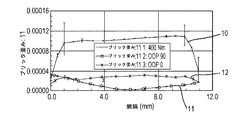
図5〜8は、半径方向スロット40の形態のねじれ影響低減構成38の効果とOOP偶力からの表面歪みに対する厚さが薄くされた周方向ウェブ52の効果が、各特徴を独立に試験するFEAモデルにより事前に確認されたグラフを示す。グラフのプロットにおいて、普通の線10は、面内適用トルクに対応する。これは望ましい信号である。円付き線11は、ねじれによる不必要な歪み(グラフ上の用語集においてOOP90とも呼ばれる)に対応する。交線付き線12は、縦方向の曲げによる不必要な歪み(グラフ上の用語集においてOOP0と呼ばれる)に対応する。
FIGS. 5-8 show that the effects of the reduced
図5は、比較基礎又は比較制御として、慣用のフレックスプレートによって生じた結果を示す。 FIG. 5 shows the results produced by a conventional flex plate as a comparison basis or comparison control.
図6において、曲げ及びねじりの両方の不必要な歪みを低減する、厚さが薄くされた周方向ウェブ52が示され、ねじれによる不必要な歪みのより顕著な低減を伴う。
In FIG. 6, a reduced
図7において、ねじれによる不必要な歪みに対して劇的な効果を有する半径方向スロット40が示されるが、縦方向の曲げによる不必要な歪みに対する効果は比較的小さい。
In FIG. 7, a
図8は、半径方向スロット40及び厚さが薄くされた周方向ウェブ52の両方の効果を示す。これら特徴の両方の使用は、曲げ及びねじれによる不必要な歪みの両方に著しい総合的な低減をもたらす。このグラフは、次の表1に示すように、両方の特徴が共に使用された場合のいくつかの驚くべき効果を示す。
FIG. 8 shows the effect of both the

驚くべきことに、特に不必要な曲げ歪みに対する特徴の組み合わせの効果は、予想を超えていた。これは、結果のすべてにわたる均等な発見ではないが、特徴の組み合わせの使用は、常に有利であり、時に驚くほど有利であることが分かった。これらの結果の顕著さは、慣用の構成と比較して不必要な歪みの少なくとも50%の低減が実現する場合、また、不必要な歪みが有益なトルクに比べて相対的に高い場合、明白となろう。 Surprisingly, the effect of the combination of features, especially on unwanted bending strains, was unexpected. While this is not an equal discovery across all of the results, it has been found that the use of feature combinations is always advantageous and sometimes surprisingly advantageous. The prominence of these results is evident when at least a 50% reduction in unwanted strain is achieved compared to conventional configurations, and when the unwanted strain is relatively high compared to useful torque. It will be.
従って、従来のトルク測定フレックスプレートを超えるいくつかの利点を与えるトルク測定フレックスプレート20が提供される。曲げ及びねじれに対する中立軸の異なる位置が特定される。縦方向の曲げによる不必要な歪みは、上述したセンサ配列の使用により、キャンセルされるか、少なくとも最小化され得る。有利には、センサ28は、ねじれに対する中立軸に位置付けられる。しかしながら、配置における不正確さは、目下存在しているねじれによる不必要な歪みをもたらし得る。半径方向スロット40が設けられ、該スロットはねじれの影響からセンサ28を分離し、そのため、更なるねじれによる不必要な歪みを低減する。厚さが薄くされた周方向ウェブ52は、曲げ及びねじれの両方から不必要な歪みを低減する点で総合的な効果を有する。半径方向スロット40及び厚さが薄くされた周方向ウェブ52の両方を設けることが、不必要な歪みを低減する点で驚くべき有益な効果を有することが示された。
Accordingly, a torque
種々の他の変更が、本発明の範囲から逸脱することなくなされ得る。フレックスプレートは、任意の適切なサイズ及び形状であり得、また、任意の適切な材料から形成され得る。半径方向スロット、軸方向スルー孔、及び周方向に延びる孔は、任意の適切なサイズ及び形状であり得る。一つの例において、スロット40は、相互に平行というよりはむしろ、実質的に半径方向に延びることができる。任意の適切な数の半径方向ウェブ、凹部及びセンサが存在することができる。
Various other changes can be made without departing from the scope of the invention. The flex plate can be any suitable size and shape, and can be formed from any suitable material. The radial slots, axial through holes, and circumferentially extending holes can be of any suitable size and shape. In one example, the
Claims (14)
前記フレックスプレートは、複数の周方向に延びるスロットを更に規定し、該スロットの一つは、各取り付け穴とフレックスプレートの外側縁との間に位置付けられ、前記フレックスプレートは、各周方向に延びるスロットと対応する軸方向スルー孔との間に延びる周方向ウェブを含み、前記各取り付け穴は、軸方向スルー孔の一つと周方向に延びるスロットの一つとの間の周方向ウェブに位置付けられ、前記各取り付け穴の中心線は、対応する軸方向スルー孔と対応する周方向ウェブと対応する周方向に延びるスロットの中心線と実質的に同じ半径上に位置する請求項1〜8のいずれか1項に記載のフレックスプレート。 The number and radial position of the mounting holes coincide with the number and radial position of the axial through holes ,
The flex plate further defines a plurality of circumferentially extending slots, wherein one of the slots is positioned between each mounting hole and the outer edge of the flex plate, the flex plate extending in each circumferential direction. Including a circumferential web extending between a slot and a corresponding axial through hole, each mounting hole being positioned in a circumferential web between one of the axial through holes and one of the circumferentially extending slots; the center line of each mounting hole, claim 1-8 is located in the corresponding axial through-hole and the center line of the corresponding circumferential webs and extending in a corresponding circumferential slots substantially the same radius on The flex plate according to item 1.
Applications Claiming Priority (3)
| Application Number | Priority Date | Filing Date | Title |
|---|---|---|---|
| GB1303219.8 | 2013-02-22 | ||
| GB1303219.8A GB2511101B (en) | 2013-02-22 | 2013-02-22 | Torque measurement flexplates |
| PCT/GB2014/050552 WO2014128506A1 (en) | 2013-02-22 | 2014-02-24 | Torque measurement flexplates |
Publications (3)
| Publication Number | Publication Date |
|---|---|
| JP2016507755A JP2016507755A (en) | 2016-03-10 |
| JP2016507755A5 JP2016507755A5 (en) | 2017-03-30 |
| JP6263556B2 true JP6263556B2 (en) | 2018-01-17 |
Family
ID=48091981
Family Applications (1)
| Application Number | Title | Priority Date | Filing Date |
|---|---|---|---|
| JP2015558555A Active JP6263556B2 (en) | 2013-02-22 | 2014-02-24 | Torque measurement flex plate |
Country Status (5)
| Country | Link |
|---|---|
| US (1) | US9702775B2 (en) |
| EP (1) | EP2959279A1 (en) |
| JP (1) | JP6263556B2 (en) |
| GB (1) | GB2511101B (en) |
| WO (1) | WO2014128506A1 (en) |
Cited By (2)
| Publication number | Priority date | Publication date | Assignee | Title |
|---|---|---|---|---|
| JP6428982B1 (en) * | 2016-12-27 | 2018-11-28 | 第一精工株式会社 | Torque sensor |
| JP2020165732A (en) * | 2019-03-28 | 2020-10-08 | 株式会社小野測器 | Torque measurement device |
Families Citing this family (10)
| Publication number | Priority date | Publication date | Assignee | Title |
|---|---|---|---|---|
| WO2014147583A1 (en) | 2013-03-20 | 2014-09-25 | Tq-Systems Gmbh | Harmonic pin ring gearing |
| CN109844480A (en) * | 2016-10-17 | 2019-06-04 | 基斯特勒控股公司 | Power and torque detector, for the force snesor module of this power and torque detector and the robot with this power and torque detector |
| DE102016122845A1 (en) * | 2016-11-28 | 2018-05-30 | Tq-Systems Gmbh | Harmonic pinion gear, torque measuring device and freewheel assembly |
| JP1594499S (en) * | 2017-02-28 | 2018-01-15 | ||
| JP6976892B2 (en) * | 2018-03-29 | 2021-12-08 | 日本電産コパル電子株式会社 | Torque sensor |
| JP6968739B2 (en) | 2018-03-29 | 2021-11-17 | 日本電産コパル電子株式会社 | Torque sensor |
| CN109214073A (en) * | 2018-08-25 | 2019-01-15 | 深圳市纯水号水处理科技有限公司 | A kind of intelligence composite material flexible member design method |
| TWI716789B (en) * | 2018-12-20 | 2021-01-21 | 財團法人工業技術研究院 | Multi-axis force sensor |
| JP6999587B2 (en) * | 2019-01-28 | 2022-01-18 | 日本電産コパル電子株式会社 | Elastic body and force sensor using it |
| EP4089296A1 (en) * | 2021-05-11 | 2022-11-16 | Centa-Antriebe Kirschey GmbH | Flexible shaft coupling and coupling membrane for such a coupling |
Family Cites Families (20)
| Publication number | Priority date | Publication date | Assignee | Title |
|---|---|---|---|---|
| JPS57169643A (en) * | 1981-04-13 | 1982-10-19 | Yamato Scale Co Ltd | Load cell for multiple components of force |
| US4573362A (en) * | 1984-07-09 | 1986-03-04 | Eaton Corporation | Multi-axis load transducer |
| DE4208522C2 (en) | 1992-03-18 | 2000-08-10 | Hottinger Messtechnik Baldwin | Torque sensor |
| DE19627385A1 (en) * | 1996-07-06 | 1998-01-08 | Bayerische Motoren Werke Ag | Wheel hub |
| EP1133682B1 (en) * | 1998-10-30 | 2004-03-17 | Vernon A. Lambson | Method and apparatus for measuring torque |
| US6253626B1 (en) * | 1999-09-02 | 2001-07-03 | Rs Technologies, Ltd. | Three-axis transducer body and strain gage arrangement therefor |
| US6441324B1 (en) * | 2000-07-28 | 2002-08-27 | Jon L. Stimpson | Weighing system for weighing railroad cars and their load |
| FR2812356B1 (en) * | 2000-07-28 | 2002-12-06 | Roulements Soc Nouvelle | BEARING COMPRISING AT LEAST ONE ELASTIC DEFORMATION ZONE AND BRAKING ASSEMBLY COMPRISING SAME |
| JP4836370B2 (en) * | 2001-09-12 | 2011-12-14 | Jfeアドバンテック株式会社 | Torque meter |
| US6871552B2 (en) * | 2002-04-12 | 2005-03-29 | Deutsches Zentrum für Luft- und Raumfahrt e.V. | Force moment sensor |
| EP1353159B1 (en) * | 2002-04-12 | 2006-02-15 | Deutsches Zentrum für Luft- und Raumfahrt e.V. | Monolithic torque sensor |
| WO2005075950A1 (en) * | 2004-02-04 | 2005-08-18 | Ono Sokki Co.,Ltd. | Torque meter |
| US7770471B2 (en) * | 2004-08-16 | 2010-08-10 | Transense Technologies Plc | Torque measurement within a powertrain |
| GB2436149B (en) * | 2006-03-15 | 2011-08-17 | Transense Technologies Plc | Torque measurement in flexible drive coupling plate |
| WO2008058164A2 (en) * | 2006-11-06 | 2008-05-15 | Quarq Technology, Inc. | Crankset based bicycle power measurement |
| US8006574B2 (en) * | 2007-11-06 | 2011-08-30 | Sram, Llc | Crankset based bicycle power measurement |
| US7743672B2 (en) * | 2008-06-06 | 2010-06-29 | Kulite Semiconductor Products, Inc. | Multiple axis load cell controller |
| CN102317750B (en) * | 2009-02-06 | 2015-07-22 | Abb股份公司 | Set of multiaxial force and torque sensor and assembling method |
| WO2010139350A1 (en) * | 2009-06-05 | 2010-12-09 | Skf Bv | Load-measuring bearing unit |
| DE202010005613U1 (en) * | 2010-06-10 | 2010-09-02 | Eduard Wille Gmbh & Co. Kg | Torque transducer with U-profile web |
-
2013
- 2013-02-22 GB GB1303219.8A patent/GB2511101B/en active Active
-
2014
- 2014-02-24 EP EP14714305.1A patent/EP2959279A1/en not_active Withdrawn
- 2014-02-24 JP JP2015558555A patent/JP6263556B2/en active Active
- 2014-02-24 WO PCT/GB2014/050552 patent/WO2014128506A1/en active Application Filing
- 2014-02-24 US US14/769,697 patent/US9702775B2/en active Active
Cited By (3)
| Publication number | Priority date | Publication date | Assignee | Title |
|---|---|---|---|---|
| JP6428982B1 (en) * | 2016-12-27 | 2018-11-28 | 第一精工株式会社 | Torque sensor |
| JP2020165732A (en) * | 2019-03-28 | 2020-10-08 | 株式会社小野測器 | Torque measurement device |
| JP7153596B2 (en) | 2019-03-28 | 2022-10-14 | 株式会社小野測器 | Torque measuring device |
Also Published As
| Publication number | Publication date |
|---|---|
| JP2016507755A (en) | 2016-03-10 |
| US9702775B2 (en) | 2017-07-11 |
| EP2959279A1 (en) | 2015-12-30 |
| GB2511101B (en) | 2017-05-10 |
| US20150377725A1 (en) | 2015-12-31 |
| GB201303219D0 (en) | 2013-04-10 |
| WO2014128506A1 (en) | 2014-08-28 |
| GB2511101A (en) | 2014-08-27 |
Similar Documents
| Publication | Publication Date | Title |
|---|---|---|
| JP6263556B2 (en) | Torque measurement flex plate | |
| JP6114709B2 (en) | Magnetoelastic sensor, load pin with this sensor, ball joint and traction coupling, method for determining the direction of the load vector | |
| US9329093B2 (en) | Determining torque in a shaft | |
| US9855991B2 (en) | Vehicle which is operable by a motor and by muscular energy and has an improved torque sensor | |
| US20090013803A1 (en) | Torque measurement within a powertrain | |
| JP2016507755A5 (en) | ||
| US20100162830A1 (en) | Torque-measuring flange | |
| EP2899522B1 (en) | Optical measurement of fastener preload | |
| Gobbi et al. | A new six-axis load cell. Part II: Error analysis, construction and experimental assessment of performances | |
| WO2015011489A1 (en) | Cutting tool with surface acoustic wave sensor | |
| JP5190826B2 (en) | Torque measurement in flexible drive coupling plates | |
| CN106908175A (en) | Axial rotation type torque sensor | |
| KR20140067650A (en) | Torque sensor | |
| JP2017101958A (en) | Test device | |
| CN111351600A (en) | Strain type torque measuring system | |
| US10378976B2 (en) | Balance devices | |
| de Oliveira et al. | Design and experimental set-up of a hybrid dynamometer applied to a fourth axis of the vertical machining center | |
| KR20110130332A (en) | Torque measurement device | |
| WO2020008836A1 (en) | Torque sensor | |
| EP2891870A1 (en) | Detection device for detecting load and moment, and artificial limb including detection device | |
| JP2013024692A (en) | Torque measuring instrument | |
| DE102010060676B4 (en) | force measuring device | |
| KR20010061162A (en) | Crank shaft for testing vibration | |
| JP2014044158A (en) | Method for measuring apex position of bar-shaped member peripheral surface | |
| KR101753627B1 (en) | Load measuring apparatus for a vehicle component |
Legal Events
| Date | Code | Title | Description |
|---|---|---|---|
| A521 | Request for written amendment filed |
Free format text: JAPANESE INTERMEDIATE CODE: A523 Effective date: 20170222 |
|
| A621 | Written request for application examination |
Free format text: JAPANESE INTERMEDIATE CODE: A621 Effective date: 20170222 |
|
| TRDD | Decision of grant or rejection written | ||
| A01 | Written decision to grant a patent or to grant a registration (utility model) |
Free format text: JAPANESE INTERMEDIATE CODE: A01 Effective date: 20171121 |
|
| A977 | Report on retrieval |
Free format text: JAPANESE INTERMEDIATE CODE: A971007 Effective date: 20171122 |
|
| A61 | First payment of annual fees (during grant procedure) |
Free format text: JAPANESE INTERMEDIATE CODE: A61 Effective date: 20171218 |
|
| R150 | Certificate of patent or registration of utility model |
Ref document number: 6263556 Country of ref document: JP Free format text: JAPANESE INTERMEDIATE CODE: R150 |
|
| R250 | Receipt of annual fees |
Free format text: JAPANESE INTERMEDIATE CODE: R250 |
|
| R250 | Receipt of annual fees |
Free format text: JAPANESE INTERMEDIATE CODE: R250 |
|
| R250 | Receipt of annual fees |
Free format text: JAPANESE INTERMEDIATE CODE: R250 |
|
| R250 | Receipt of annual fees |
Free format text: JAPANESE INTERMEDIATE CODE: R250 |