JP6262686B2 - Motor controller having smoothing capacitor life prediction means - Google Patents
Motor controller having smoothing capacitor life prediction means Download PDFInfo
- Publication number
- JP6262686B2 JP6262686B2 JP2015090832A JP2015090832A JP6262686B2 JP 6262686 B2 JP6262686 B2 JP 6262686B2 JP 2015090832 A JP2015090832 A JP 2015090832A JP 2015090832 A JP2015090832 A JP 2015090832A JP 6262686 B2 JP6262686 B2 JP 6262686B2
- Authority
- JP
- Japan
- Prior art keywords
- smoothing capacitor
- power
- deterioration characteristic
- motor control
- time
- Prior art date
- Legal status (The legal status is an assumption and is not a legal conclusion. Google has not performed a legal analysis and makes no representation as to the accuracy of the status listed.)
- Active
Links
Images


Classifications
-
- H—ELECTRICITY
- H02—GENERATION; CONVERSION OR DISTRIBUTION OF ELECTRIC POWER
- H02P—CONTROL OR REGULATION OF ELECTRIC MOTORS, ELECTRIC GENERATORS OR DYNAMO-ELECTRIC CONVERTERS; CONTROLLING TRANSFORMERS, REACTORS OR CHOKE COILS
- H02P27/00—Arrangements or methods for the control of AC motors characterised by the kind of supply voltage
- H02P27/04—Arrangements or methods for the control of AC motors characterised by the kind of supply voltage using variable-frequency supply voltage, e.g. inverter or converter supply voltage
- H02P27/06—Arrangements or methods for the control of AC motors characterised by the kind of supply voltage using variable-frequency supply voltage, e.g. inverter or converter supply voltage using dc to ac converters or inverters
-
- H—ELECTRICITY
- H02—GENERATION; CONVERSION OR DISTRIBUTION OF ELECTRIC POWER
- H02M—APPARATUS FOR CONVERSION BETWEEN AC AND AC, BETWEEN AC AND DC, OR BETWEEN DC AND DC, AND FOR USE WITH MAINS OR SIMILAR POWER SUPPLY SYSTEMS; CONVERSION OF DC OR AC INPUT POWER INTO SURGE OUTPUT POWER; CONTROL OR REGULATION THEREOF
- H02M1/00—Details of apparatus for conversion
- H02M1/32—Means for protecting converters other than automatic disconnection
-
- G—PHYSICS
- G01—MEASURING; TESTING
- G01R—MEASURING ELECTRIC VARIABLES; MEASURING MAGNETIC VARIABLES
- G01R27/00—Arrangements for measuring resistance, reactance, impedance, or electric characteristics derived therefrom
- G01R27/02—Measuring real or complex resistance, reactance, impedance, or other two-pole characteristics derived therefrom, e.g. time constant
- G01R27/26—Measuring inductance or capacitance; Measuring quality factor, e.g. by using the resonance method; Measuring loss factor; Measuring dielectric constants ; Measuring impedance or related variables
- G01R27/2605—Measuring capacitance
-
- G—PHYSICS
- G01—MEASURING; TESTING
- G01R—MEASURING ELECTRIC VARIABLES; MEASURING MAGNETIC VARIABLES
- G01R31/00—Arrangements for testing electric properties; Arrangements for locating electric faults; Arrangements for electrical testing characterised by what is being tested not provided for elsewhere
-
- H—ELECTRICITY
- H02—GENERATION; CONVERSION OR DISTRIBUTION OF ELECTRIC POWER
- H02M—APPARATUS FOR CONVERSION BETWEEN AC AND AC, BETWEEN AC AND DC, OR BETWEEN DC AND DC, AND FOR USE WITH MAINS OR SIMILAR POWER SUPPLY SYSTEMS; CONVERSION OF DC OR AC INPUT POWER INTO SURGE OUTPUT POWER; CONTROL OR REGULATION THEREOF
- H02M5/00—Conversion of ac power input into ac power output, e.g. for change of voltage, for change of frequency, for change of number of phases
- H02M5/40—Conversion of ac power input into ac power output, e.g. for change of voltage, for change of frequency, for change of number of phases with intermediate conversion into dc
- H02M5/42—Conversion of ac power input into ac power output, e.g. for change of voltage, for change of frequency, for change of number of phases with intermediate conversion into dc by static converters
- H02M5/44—Conversion of ac power input into ac power output, e.g. for change of voltage, for change of frequency, for change of number of phases with intermediate conversion into dc by static converters using discharge tubes or semiconductor devices to convert the intermediate dc into ac
- H02M5/453—Conversion of ac power input into ac power output, e.g. for change of voltage, for change of frequency, for change of number of phases with intermediate conversion into dc by static converters using discharge tubes or semiconductor devices to convert the intermediate dc into ac using devices of a triode or transistor type requiring continuous application of a control signal
- H02M5/458—Conversion of ac power input into ac power output, e.g. for change of voltage, for change of frequency, for change of number of phases with intermediate conversion into dc by static converters using discharge tubes or semiconductor devices to convert the intermediate dc into ac using devices of a triode or transistor type requiring continuous application of a control signal using semiconductor devices only
- H02M5/4585—Conversion of ac power input into ac power output, e.g. for change of voltage, for change of frequency, for change of number of phases with intermediate conversion into dc by static converters using discharge tubes or semiconductor devices to convert the intermediate dc into ac using devices of a triode or transistor type requiring continuous application of a control signal using semiconductor devices only having a rectifier with controlled elements
Description
本発明は、三相交流入力側から供給された交流電力を直流電力に変換して直流リンクへ出力したのちさらにモータの駆動のための交流電力に変換してモータへ供給するモータ制御装置に関し、特に、直流リンクに設けられた平滑コンデンサの寿命を予測する寿命予測手段を有するモータ制御装置に関する。 The present invention relates to a motor control device that converts alternating current power supplied from a three-phase alternating current input side into direct current power and outputs the direct current link to alternating current power for driving the motor and supplies the motor to the motor. In particular, the present invention relates to a motor control device having a life prediction means for predicting the life of a smoothing capacitor provided in a DC link.
工作機械、産業機械、鍛圧機械、射出成形機、あるいは各種ロボット内のモータを駆動するモータ制御装置においては、交流電源側から入力された交流電力を順変換器により直流電力に一旦変換したのち、さらにこの直流電力を逆変換器により交流電力に変換し、この交流電力をモータの駆動電力として用いている。 In motor control devices that drive motors in machine tools, industrial machines, forging machines, injection molding machines, or various robots, once AC power input from the AC power supply side is converted into DC power by a forward converter, Furthermore, this DC power is converted into AC power by an inverse converter, and this AC power is used as drive power for the motor.
図4は、一般的なモータ制御装置の構成を示す図である。モータ制御装置100は、商用三相交流電源(以下、単に「交流電源」と称する。)103からの交流電力を直流電力に変換する順変換器101と、順変換器101から出力された直流電力をモータ104の駆動電力として供給される所望の周波数の交流電力に変換しまたはモータ104から回生される交流電力を直流電力に変換する逆変換器102と、を備え、当該逆変換器102の交流側に接続されたモータ104の速度、トルク、もしくは回転子の位置を制御する。順変換器101と逆変換器102とは直流リンク(DCリンク)を介して接続される。直流リンクには、順変換器101の直流出力を平滑化するために平滑コンデンサ(DCリンクコンデンサ)105が設けられる。一般に、駆動軸(送り軸および主軸)が複数ある場合は、各駆動軸を駆動するためにモータも複数設けられる。逆変換器は、複数の駆動軸に対応してそれぞれ設けられる各モータに個別に駆動電力を供給してモータを駆動制御するために、モータの個数と同数個、並列接続される。一方、順変換器については、モータ制御装置のコストや占有スペースを低減する目的で、複数の逆変換器に対して1個が設けられることが多い。なお、図4では、図面を簡明なものとするために、モータ104の個数を1個としており、したがって逆変換器102は1個である。
FIG. 4 is a diagram illustrating a configuration of a general motor control device. The
順変換器と逆変換器との間の直流リンクに設けられる平滑コンデンサは、充放電の繰り返しによりその静電容量(以下、単に「容量」と称する。)が減少する有限寿命の部品であることが一般的に知られている。充放電の繰り返しにより平滑コンデンサが劣化して容量が低下すると、直流リンクに流れるリプル電流が増加し、直流電圧の変動が大きくなるという問題が生じる。 The smoothing capacitor provided in the DC link between the forward converter and the reverse converter is a component with a finite life in which its electrostatic capacity (hereinafter simply referred to as “capacitance”) decreases due to repeated charging and discharging. Is generally known. When the smoothing capacitor is deteriorated due to repeated charge and discharge and the capacity is reduced, the ripple current flowing in the DC link increases, causing a problem that the fluctuation of the DC voltage increases.
また、モータ制御装置の種類によっては、平滑コンデンサに蓄積されたエネルギーをモータの加速時に使用することで、交流電源からの供給電力を減らし、電源設備容量の低減を行うものもある。このような場合、充放電の繰り返しにより平滑コンデンサが劣化して容量が低下すると、蓄積できるエネルギーが低下し、モータ加速時に十分なエネルギーを供給できず、例えば工作機械の場合は加工工程に何らかの障害が生じてしまう可能性もある。 Some types of motor control devices use energy stored in the smoothing capacitor when accelerating the motor, thereby reducing the power supplied from the AC power source and reducing the power supply equipment capacity. In such a case, if the smoothing capacitor deteriorates due to repeated charge and discharge and the capacity decreases, the energy that can be stored decreases, and sufficient energy cannot be supplied during motor acceleration. May occur.
したがって、寿命が到来した平滑コンデンサを最適な時期に交換するためには、平滑コンデンサの容量を的確に把握し、いつ寿命が到来するかを予測することが重要である。 Therefore, in order to replace a smoothing capacitor that has reached the end of its life at an optimal time, it is important to accurately grasp the capacity of the smoothing capacitor and predict when the end of the life will come.
例えば、インバータ(逆変換器)の電源遮断時の直流リンクに設けられた電解コンデンサの電圧低下の状況から、電解コンデンサの寿命を判定する方法がある(例えば、特許文献1参照。)。 For example, there is a method of determining the life of the electrolytic capacitor from the state of voltage drop of the electrolytic capacitor provided in the DC link when the power source of the inverter (inverter) is shut off (for example, see Patent Document 1).
また例えば、直流リンクに設けられた電解コンデンサの漏れ電流の増加状況から、電解コンデンサの寿命を予測する方法がある(例えば、特許文献2参照。)。 Further, for example, there is a method for predicting the lifetime of the electrolytic capacitor from the increase in leakage current of the electrolytic capacitor provided in the DC link (see, for example, Patent Document 2).
上述のように、モータ制御装置内の順変換器と逆変換器との間の直流リンクに設けられた平滑コンデンサが充放電の繰り返しにより劣化して容量が減少すると、直流リンクに流れるリプル電流が増加し、直流電圧の変動が大きくなるという問題がある。また、モータ制御装置の種類によっては、平滑コンデンサに蓄積されたエネルギーをモータの加速時に使用することで、交流電源からの供給電力を減らし、電源設備容量の低減を行うものがあるが、平滑コンデンサの容量が低下すると、蓄積できるエネルギーが低下し、モータ加速時に十分なエネルギーを供給できない問題がある。平滑コンデンサの容量を的確に予測できなければ、平滑コンデンサの交換のタイミングを逸して直流リンクに大きなリプル電流や直流電圧変動を発生させてしまうことになりかねない。またあるいは、まだ寿命のある平滑コンデンサを不必要に早く交換してしまう事態にもなりかねず、不経済である。このように、平滑コンデンサの容量を把握して寿命が到来したか否かを的確に予測することは重要である。 As described above, when the smoothing capacitor provided in the DC link between the forward converter and the reverse converter in the motor control device deteriorates due to repeated charging and discharging and the capacity decreases, the ripple current flowing through the DC link is reduced. There is a problem that the fluctuation of the DC voltage increases. Some types of motor control devices use the energy stored in the smoothing capacitor when accelerating the motor, reducing the power supplied from the AC power supply and reducing the capacity of the power supply equipment. When the capacity of the battery decreases, the energy that can be stored decreases, and there is a problem that sufficient energy cannot be supplied during motor acceleration. If the capacity of the smoothing capacitor cannot be accurately predicted, the replacement timing of the smoothing capacitor may be lost and a large ripple current or DC voltage fluctuation may be generated in the DC link. Alternatively, the smoothing capacitor that still has a lifetime may be replaced unnecessarily quickly, which is uneconomical. Thus, it is important to grasp the capacity of the smoothing capacitor and accurately predict whether or not the lifetime has come.
例えば、特許文献1(特開平8−80055号公報)に記載された発明によれば、インバータ(逆変換器)の電源遮断時の直流リンクに設けられた電解コンデンサの電圧低下を検出した時点での電解コンデンサの寿命判定はできるが、将来的にいつ頃寿命が到来するのかということは予測することはできない。そのため、電解コンデンサの寿命予測に基づいてモータ制御装置の運転条件を見直すといった柔軟な対応をとることができない。また、将来的に到来する電解コンデンサの寿命に備えた電解コンデンサの効率的な交換計画を立てることができない。また、特許文献1に記載された発明では、電解コンデンサの容量を放電時に測定するので、このための放電手段が別途必要となる。 For example, according to the invention described in Patent Document 1 (Japanese Patent Laid-Open No. 8-80055), when a voltage drop of an electrolytic capacitor provided in a DC link at the time of power-off of an inverter (inverter) is detected. However, it is impossible to predict when the lifetime will come in the future. Therefore, it is not possible to take a flexible measure such as reviewing the operating conditions of the motor control device based on the life prediction of the electrolytic capacitor. In addition, it is impossible to make an efficient replacement plan for the electrolytic capacitor in preparation for the future life of the electrolytic capacitor. Moreover, in the invention described in Patent Document 1, the capacity of the electrolytic capacitor is measured at the time of discharging, and thus a discharging means for this purpose is separately required.
また、特許文献2(特開2007−318872号公報)に記載された発明は、漏れ電流が増加傾向に転じて3、4日で寿命に達するという実験結果に基づき電解コンデンサの寿命を予測するものである。つまり、電解コンデンサが完全に故障する直前になったときに初めて寿命到来を予測することはできるが、中長期先(例えば数か月先や数年先)に到来する寿命については予測することはできない。中長期先に到来する寿命を把握することができれば、寿命が到来するまでの間はモータ制御装置の運転条件を電解コンデンサが極力劣化しないようなものに変更するといった対応を余裕を持ってとることができ、その劣化抑止の効果も高い。しかしながら、3、4日後先といったような短期間先の寿命予測では、モータ制御装置の運転条件を電解コンデンサが極力劣化しないようなものに変更したとしてもその劣化抑止の効果は小さい。また、特許文献2に記載された発明では、電解コンデンサの漏れ電流を測定するので、このための漏れ電流測定手段が別途必要となる。
Further, the invention described in Patent Document 2 (Japanese Patent Laid-Open No. 2007-318872) predicts the life of an electrolytic capacitor based on the experimental result that the leakage current starts to increase and reaches the life in 3 or 4 days. It is. In other words, it is possible to predict the end of life for the first time just before the electrolytic capacitor completely fails, but it is not possible to predict the end of life that will come in the medium to long term (for example, months or years ahead). Can not. If it is possible to grasp the life that will come in the mid to long term, take sufficient steps to change the operating conditions of the motor controller so that the electrolytic capacitor does not deteriorate as much as possible until the end of the life. The effect of inhibiting deterioration is high. However, in the life prediction ahead of a short period of time, such as three or four days later, even if the operating conditions of the motor control device are changed so that the electrolytic capacitor does not deteriorate as much as possible, the effect of suppressing the deterioration is small. Moreover, in the invention described in
従って本発明の目的は、上記問題に鑑み、順変換器と逆変換器との間の直流リンクにおける平滑コンデンサの寿命を的確に予測することができるモータ制御装置を提供することにある。 Accordingly, an object of the present invention is to provide a motor control device capable of accurately predicting the life of a smoothing capacitor in a DC link between a forward converter and an inverse converter in view of the above problems.
上記目的を実現するために、本発明によるモータ制御装置は、交流電源側から供給された交流電力を直流電力に変換する順変換器と、順変換器の直流側である直流リンクに設けられる平滑コンデンサと、直流リンクにおける直流電力とモータの駆動電力もしくは回生電力である交流電力とを相互電力変換する逆変換器と、平滑コンデンサの容量を測定するコンデンサ容量測定手段と、コンデンサ容量測定手段により測定された平滑コンデンサの容量の測定値と当該測定が行われたときの日付または日付および時刻の両方とからなるデータを複数記録するデータ記録手段と、データ記録手段に記録された複数のデータに基づいて、経過時間に対する平滑コンデンサの容量の変化を示す劣化特性線を算出する劣化特性算出手段と、劣化特性算出手段により算出された劣化特性線に基づいて、平滑コンデンサの寿命が到来する時期を予測する寿命予測手段と、を備える。 In order to achieve the above object, a motor control device according to the present invention includes a forward converter that converts AC power supplied from an AC power supply side to DC power, and a smoothing link provided on a DC link that is the DC side of the forward converter. Measured by a capacitor, an inverse converter that mutually converts DC power in the DC link and AC power that is driving power or regenerative power of the motor, capacitor capacity measuring means that measures the capacity of the smoothing capacitor, and capacitor capacity measuring means Based on the data recording means for recording a plurality of data consisting of the measured value of the capacitance of the smoothing capacitor and the date or both of the date and time when the measurement was performed, and the plurality of data recorded in the data recording means A deterioration characteristic calculating means for calculating a deterioration characteristic line indicating a change in the capacity of the smoothing capacitor with respect to the elapsed time; Based on the deterioration characteristic line calculated by, comprising a lifetime estimation means for estimating a time when the life of the smoothing capacitor arrives, the.
ここで、寿命予測手段は、劣化特性線が所定の劣化判定レベル以下になるときの日付または日付および時刻の両方を算出し、当該日付または日付および時刻の両方を平滑コンデンサの寿命が到来する時期として確定するようにしてもよい。 Here, the life prediction means calculates the date or both of the date and time when the deterioration characteristic line falls below a predetermined deterioration judgment level, and both the date or date and time is the time when the life of the smoothing capacitor comes. It may be determined as follows.
また、劣化特性算出手段は、データ記録手段に記録された複数のデータに基づいて、劣化特性線を、nを自然数としたときのn次関数式として算出するようにしてもよい。 Further, the deterioration characteristic calculating means may calculate the deterioration characteristic line as an nth order function expression where n is a natural number based on a plurality of data recorded in the data recording means.
また、劣化特性算出手段は、データ記録手段に記録された複数のデータに基づき最小二乗法により劣化特性線を算出するようにしてもよい。 Further, the deterioration characteristic calculation means may calculate the deterioration characteristic line by a least square method based on a plurality of data recorded in the data recording means.
また、コンデンサ容量測定手段は、平滑コンデンサに印加される直流電圧と、順変換器に入力される電流もしくは順変換器から出力される電流と、に基づいて、平滑コンデンサの容量を測定するようにしてもよい。 The capacitor capacity measuring means measures the capacity of the smoothing capacitor based on the DC voltage applied to the smoothing capacitor and the current input to the forward converter or the current output from the forward converter. May be.
本発明によれば、順変換器と逆変換器との間の直流リンクにおける平滑コンデンサの寿命を正確に予測することができるモータ制御装置を実現することができる。本発明によれば、現状の使用状態が継続された場合の平滑コンデンサの寿命到来の時期を、その直前になってからではなく中長期間前から予測することができるので、平滑コンデンサの寿命予測に基づいてモータ制御装置の運転条件を見直すといった柔軟な対応が取り易くなり、また、将来的に到来する平滑コンデンサの寿命に備えた平滑コンデンサの効率的な交換計画を立て易くなる。また、本発明は、モータ制御装置がモータの駆動制御に本来的に必要な電流検出手段および電圧検出手段により検出された電流および電圧を用いて、平滑コンデンサの寿命到来の時期を予測することができるので、寿命予測のための新たな検出手段を設ける必要がない。したがって、既存のモータ制御装置にも後付けで適用することも容易である。また、特許文献1に記載された発明におけるような放電手段や特許文献2に記載された発明におけるような漏れ電流測定手段を別途設ける必要もない。
ADVANTAGE OF THE INVENTION According to this invention, the motor control apparatus which can estimate the lifetime of the smoothing capacitor in the DC link between a forward converter and an inverse converter correctly can be implement | achieved. According to the present invention, it is possible to predict the life of the smoothing capacitor when the current usage state is continued, not from just before that, but from the middle to long term. Based on this, it becomes easy to take a flexible measure such as revising the operating condition of the motor control device, and it is easy to make an efficient replacement plan for the smoothing capacitor in preparation for the future life of the smoothing capacitor. According to the present invention, the motor control device can predict the end of the life of the smoothing capacitor by using the current and voltage detected by the current detection means and the voltage detection means which are essentially necessary for driving control of the motor. Therefore, it is not necessary to provide a new detection means for life prediction. Therefore, it can be easily applied to an existing motor control device as a retrofit. Further, there is no need to separately provide a discharging means as in the invention described in Patent Document 1 or a leakage current measuring means as in the invention described in
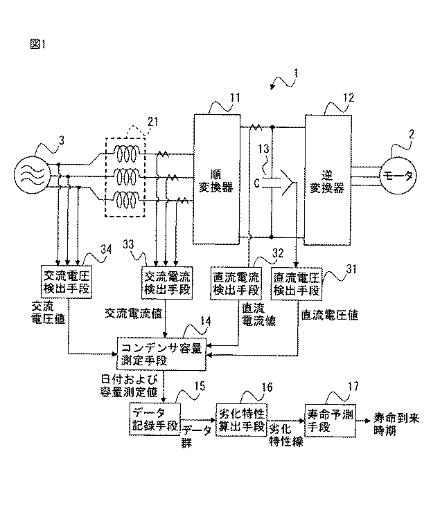
図1は、本発明の実施例によるモータ制御装置の原理ブロック図である。以降、異なる図面において同じ参照符号が付されたものは同じ機能を有する構成要素であることを意味するものとする。なお、以下で説明する実施例では、モータ制御装置1の三相交流入力側には交流電源3が接続され、モータ制御装置1の交流モータ側には三相のモータ2が接続される。なお、ここでは1個のモータ2を駆動制御するモータ制御装置1について説明するが、モータ制御装置1により駆動制御するモータ2の個数は、本発明を特に限定するものではなく、複数個のモータ2を駆動制御するモータ制御装置にも適用可能である。また、モータ制御装置によって駆動されるモータ2の種類についても本発明を特に限定するものではなく、例えば誘導モータであっても同期モータであってもよい。
FIG. 1 is a principle block diagram of a motor control device according to an embodiment of the present invention. Hereinafter, components having the same reference numerals in different drawings mean components having the same functions. In the embodiment described below, an AC power source 3 is connected to the three-phase AC input side of the motor control device 1, and a three-
本発明の実施例によるモータ制御装置1は、順変換器11と、平滑コンデンサ13と、逆変換器12と、コンデンサ容量測定手段14と、データ記録手段15と、劣化特性算出手段16と、寿命予測手段17とを備える。また、モータ制御装置1は、平滑コンデンサ13に印加される直流電圧を検出するための直流電圧検出手段31と、順変換器11の直流出力側から出力される直流電流を検出するための直流電流検出手段32もしくは順変換器11の三相交流入力側から供給される交流電流を検出するための交流電流検出手段33と、交流電源3の交流電圧を検出するための交流電圧検出手段34とを備えるが、これら直流電圧検出手段31、直流電流検出手段32もしくは交流電流検出手段33、および交流電圧検出手段34は、モータ2を駆動制御するために必要な電流および電圧を検出するためにモータ制御装置に一般的に備えられるものである。なお、本発明の実施例では、直流電流検出手段32および交流電流検出手段33についてはいずれか一方を備えればよいが、図1においては電流検出手段32および交流電流検出手段33の両方を図示している。
The motor control device 1 according to the embodiment of the present invention includes a forward converter 11, a smoothing
順変換器11は、商用の交流電源3のある三相交流入力側から供給された交流電力を整流し、順変換器11の直流出力側である直流リンク(DCリンク)に直流電力を出力する。本発明では、用いられる順変換器11の実施形態は特に限定されず、例えばダイオード整流回路、あるいは内部にスイッチング素子を備えるPWM制御方式の整流回路などがある。順変換器11の三相交流入力側には交流リアクトル21が接続される。
The forward converter 11 rectifies the AC power supplied from the three-phase AC input side of the commercial AC power supply 3 and outputs the DC power to the DC link (DC link) on the DC output side of the forward converter 11. . In the present invention, the embodiment of the forward converter 11 used is not particularly limited, and examples thereof include a diode rectifier circuit or a PWM control type rectifier circuit having a switching element therein. An
順変換器11と逆変換器12とは、直流リンクを介して接続される。逆変換器12は、直流リンクにおける直流電力とモータ2の駆動電力もしくは回生電力である交流電力との間で双方向に電力変換することができるものである。逆変換器12は、例えばPWMインバータなどのような、内部にスイッチング素子を有する変換回路として構成される。逆変換器12は、直流リンク側から供給される直流電力を、上位制御装置(図示せず)から受信したモータ駆動指令に基づき内部のスイッチング素子をスイッチング動作させ、モータ2を駆動するための所望の電圧および所望の周波数の三相交流電力に変換する。モータ2は、供給された電圧可変および周波数可変の三相交流電力に基づいて動作することになる。また、モータ2の制動時には回生電力が発生するが、上位制御装置から受信したモータ駆動指令に基づき、モータ2で発生した回生電力である交流電力を、直流電力へ変換して直流リンクへ戻す。なお、モータ制御装置1で複数のモータ2を駆動制御する場合には、各モータ2に個別に駆動電力を供給してモータ2を駆動制御するために、逆変換器12は、モータ2の個数と同数個、並列接続される。
The forward converter 11 and the
平滑コンデンサ13は、順変換器11の直流側と逆変換器12の直流側とを接続する直流リンクに設けられる。平滑コンデンサ13は、順変換器11もしくは逆変換器12の直流出力の脈動分を抑える機能とともに、順変換器11もしくは逆変換器12から出力される直流電力を一時的に蓄積する機能も有する。平滑コンデンサ13は、モータ制御装置1の電源投入後から実際にモータ2を駆動する制御を開始する前までの間に、初期充電手段(図示せず)によって、順変換器11から出力された直流電力で初期充電される。なお、図1では逆変換器12を1個設けた例を示したが、例えば逆変換器12が複数個並列接続される場合は、各逆変換器12の直流入力側に平滑コンデンサ13がそれぞれ設けられ、したがって、平滑コンデンサ13についても互いに並列接続された関係を有することになる。
The smoothing
コンデンサ容量測定手段14は、本実施例では、平滑コンデンサ13に印加される直流電圧と、順変換器11に入力される電流もしくは順変換器11から出力される電流と、に基づいて、平滑コンデンサ13の容量を測定する。ここでは、コンデンサ容量測定手段14による平滑コンデンサ13の容量の測定方法として、2つの具体例について説明する。
In this embodiment, the capacitor capacity measuring means 14 is based on the DC voltage applied to the smoothing
第1の具体例は、初期充電時に平滑コンデンサ13に流入する電荷量に基づいて平滑コンデンサ13の容量Cの測定するものである。
In the first specific example, the capacitance C of the smoothing
上述したようにモータ制御装置1の電源投入後から実際にモータ2を駆動する制御を開始する前までの間に、平滑コンデンサ13は、初期充電手段(図示せず)によって、順変換器11から出力された直流電力で初期充電される。平滑コンデンサ13の容量をC、初期充電手段による初期充電動作開始前の時点における直流電圧検出手段31により検出された平滑コンデンサ13に印加される直流電圧をV0としたとき、初期充電動作開始前に平滑コンデンサ13に蓄積されていた残存電荷量Q0は、式1のように表すことができる。
As described above, the smoothing
初期充電手段による初期充電動作終了後の時点における平滑コンデンサ13に蓄積されている電荷量Q1は、初期充電動作終了後の時点における直流電圧検出手段31により検出された平滑コンデンサ13に印加される直流電圧をV1としたとき、式2のように表すことができる。
The charge amount Q 1 accumulated in the smoothing
初期充電手段による初期充電動作により平滑コンデンサ13に蓄積される電荷量は、式3に示すようにΔQだけ増加する。
The amount of charge accumulated in the smoothing
式3で示される電荷量の増加分ΔQは、直流電流検出手段32により検出された初期充電期間中に順変換器11から出力される電流Iが平滑コンデンサ13に流入することにより発生することから、式4が成り立つ。
The increase ΔQ in the amount of charge represented by Equation 3 is generated when the current I output from the forward converter 11 flows into the smoothing
式1および式2を式4に代入すると、式5が得られる。
Substituting Equation 1 and
よってコンデンサ容量測定手段14は、初期充電動作開始前の時点における直流電圧検出手段31により検出された平滑コンデンサ13に印加される直流電圧V0と、初期充電動作終了後の時点における直流電圧検出手段31により検出された平滑コンデンサ13に印加される直流電圧V1と、直流電流検出手段32により検出された初期充電期間中に順変換器11から出力される電流Iと、を用いて式5に基づいて平滑コンデンサ13の容量を測定する。なお、この代替例として、式4および式5で用いられる電流Iを、交流電流検出手段33によって検出される順変換器11の三相交流入力側から供給される交流電流としてもよい。ただしこの場合、平滑コンデンサ13の容量の測定値Cは順変換器11の損失分に起因する誤差を含んだものとなるので、詳細については後述するが、「劣化判定レベル」については、平滑コンデンサ13を一番最初に使用開始する時点の平滑コンデンサ13の容量に対する割合として設定するのが好ましい。
Therefore, the capacitor capacity measuring means 14 includes the DC voltage V 0 applied to the smoothing
第2の具体例は、順変換器11がPWM制御方式の整流回路である場合において、平滑コンデンサの初期充電後に実行される初期昇圧動作の前後の平滑コンデンサ13の蓄積エネルギーの変化量に基づいて平滑コンデンサ13の容量Cの測定するものである。
The second specific example is based on the amount of change in the stored energy of the smoothing
一般に、順変換器11が内部にスイッチング素子を備えるPWM制御方式の整流回路である場合、原理的に交流電源3の交流電圧の波高値以上の値の直流電圧を出力させる必要がある。そのため、平滑コンデンサ13に対する初期充電動作完了後は、順変換器11内のスイッチング素子のスイッチング動作を行い、平滑コンデンサ13の両端の直流電圧を交流電源3側の交流電圧の波高値よりも大きい電圧まで昇圧する「初期昇圧動作」を行う。初期充電動作および初期昇圧動作の完了後、逆変換器12は電力変換動作を開始してモータ2に駆動電力を供給する通常動作モードに移行し、逆変換器12から出力された交流の駆動電力に基づきモータ2は駆動することになる。順変換器11から出力される電力エネルギーをPとし、平滑コンデンサ13の初期充電完了後であって初期昇圧開始前の時点における直流電圧検出手段31により検出された平滑コンデンサ13に印加される直流電圧をV1とし、平滑コンデンサ13の初期昇圧完了後であってモータ2の駆動開始前の時点における直流電圧検出手段31により検出された平滑コンデンサ13に印加される直流電圧をV2としたとき、平滑コンデンサの初期充電後に実行される初期昇圧動作の前後の平滑コンデンサ13の蓄積エネルギーの変化として式6の関係式が成り立つ。なお、電力エネルギーPは、直流電圧検出手段31により検出される平滑コンデンサ13に印加される直流電圧と、直流電流検出手段32により検出される順変換器11の直流出力側から出力される直流電流との積として求めればよい。
In general, when the forward converter 11 is a PWM control type rectifier circuit having a switching element therein, in principle, it is necessary to output a DC voltage having a value equal to or higher than the peak value of the AC voltage of the AC power supply 3. For this reason, after the initial charging operation for the smoothing
式6を変形して式7が得られる。 Equation 7 is transformed to obtain Equation 7.
よってコンデンサ容量測定手段14は、初期充電完了後であって初期昇圧開始前の時点における直流電圧検出手段31により検出された平滑コンデンサ13に印加される直流電圧V1と、初期昇圧完了後であってモータ2の駆動開始前の時点における直流電圧検出手段31により検出された平滑コンデンサ13に印加される直流電圧V2と、順変換器11から出力される電力エネルギーPと、を用いて式7に基づいて平滑コンデンサ13の容量Cを測定する。なお、この代替例として、式6および式7で用いられる電力エネルギーPを、交流電流検出手段33によって検出される順変換器11の三相交流入力側から供給される交流電流と、交流電圧検出手段34によって検出される交流電圧と、の積としてもよい。ただしこの場合、平滑コンデンサ13の容量の測定値Cは順変換器11の損失分に起因する誤差を含んだものとなるので、詳細については後述するが、「劣化判定レベル」については、平滑コンデンサ13を一番最初に使用開始する時点の平滑コンデンサ13の容量に対する割合として設定するのが好ましい。
Therefore, the capacitor capacity measuring means 14 has the DC voltage V 1 applied to the smoothing
上述のコンデンサ容量測定手段14による平滑コンデンサ13の容量の測定は、月日を改めて複数回行うものとするが、定期的に行われても不定期に行われてもよい。例えば、モータ制御装置1の電源投入ごとに毎回必ず行うようにしてもよく、あるいは何回かごとの電源投入の際に行うようにしてもよく、あるいは作業者が操作盤やパソコン等のユーザインタフェースを介して入力した測定指令をモータ制御装置1が受信したときに行うようにしてもよい。
The measurement of the capacity of the smoothing
データ記録手段15は、コンデンサ容量測定手段14により測定された平滑コンデンサ13の容量の測定値Cと、当該測定が行われたときの「日付」または「日付および時刻の両方」と、からなるデータを複数記録する。「日付」は年月日を意味し、「日付および時刻の両方」は、年月日および時刻を含む意味であるが、以下、本明細書では、説明を簡明なものとするために、「日付のみ」の場合と「日付および時刻の両方」の場合とを含む概念として、単に「日時」との用語を用いる。
The data recording means 15 is data composed of the measured value C of the capacitance of the smoothing
劣化特性算出手段16は、データ記録手段15に記録された複数のデータに基づいて、経過時間に対する平滑コンデンサ13の容量の変化を示す劣化特性線を算出する。劣化特性線は、日時を独立変数としたときのn次関数式(ただし、nは自然数)で平滑コンデンサの容量を表すものであり、一方の軸(例えばX軸)が日時を示しもう一方の軸(例えばY軸)が平滑コンデンサ13の容量を表すような平面座標系上に表される。平滑コンデンサ13は充放電の繰り返しにより劣化してその容量が減少することから、劣化特性線は、日数の経過につれて平滑コンデンサ13の容量が減少する傾向を示すものとなる。
The deterioration
例えば、n次関数式の次数については作業者が予め設定しておき、n次関数式の係数については劣化特性算出手段16により、データ記録手段15に記録された複数のデータに基づいて最小二乗法にて算出する。図2は、劣化特性線の一例を示す図である。図示の例では、データ記録手段15により記録された平滑コンデンサ13の容量の測定値Cと当該測定が行われたときの日時とからなるデータ(図示の例では8個)を黒丸で表しており、劣化特性線(図中、実線で示す)は一例として1次関数式としている。
For example, the order of the nth-order function formula is set in advance by the operator, and the coefficient of the nth-order function formula is determined by the deterioration characteristic calculation means 16 based on a plurality of data recorded in the data recording means 15. Calculated by multiplication. FIG. 2 is a diagram illustrating an example of a deterioration characteristic line. In the illustrated example, data (8 in the illustrated example) consisting of the measured value C of the capacitance of the smoothing
またあるいは、劣化特性算出手段16による劣化特性線の算出処理をより単純化して、2つの時点の平滑コンデンサ13の容量の測定結果に基づいて、1次関数式からなる劣化特性線を算出してもよい。例えば、平滑コンデンサ13を一番最初に使用開始する時点の平滑コンデンサ13の容量の測定値とそのときの日時とからなるデータと、当該一番最初に使用開始した時点からある程度の日数、月数もしくは年数が経過した時点の平滑コンデンサ13の容量の測定値とそのときの日時とからなるデータとを用いて直線近似し、1次関数式からなる劣化特性線を算出してもよい。
Alternatively, the deterioration characteristic line calculation process by the deterioration characteristic calculation means 16 is further simplified, and a deterioration characteristic line consisting of a linear function equation is calculated based on the measurement results of the capacitance of the smoothing
寿命予測手段17は、劣化特性算出手段16により算出された劣化特性線に基づいて、平滑コンデンサの寿命が到来する時期を予測する。具体的には、寿命予測手段17は、一方の軸(例えばX軸)が日時を示しもう一方の軸(例えばY軸)が平滑コンデンサ13の容量を表す平面座標系上において、n次関数式で表される劣化特性線と予め設定された劣化判定レベルとの交点をn次方程式を解くことで算出し、当該交点のうちの日時を表す座標を、平滑コンデンサの寿命が到来する時期として確定する。なお、図2に示す例では、劣化判定レベルを一点鎖線で表している。寿命予測手段17により予測された寿命到来時期は、例えばモータ制御装置1に設けられた操作盤のディスプレイあるいは携帯端末やパソコンのディスプレイに、文字や絵柄にて表示させることで、作業者に知らせる。またあるいは、予測された寿命到来時期を、スピーカを通じて音声にて作業者に知らせるようにしてもよい。またあるいは、予測された寿命到来時期を記録装置に保存しておき、後日ディスプレイに表示させたりスピーカから音声出力できるようにしてもよい。
The life prediction means 17 predicts the time when the life of the smoothing capacitor comes based on the deterioration characteristic line calculated by the deterioration characteristic calculation means 16. Specifically, the life prediction means 17 has an n-order function formula on a plane coordinate system in which one axis (for example, the X axis) indicates the date and time and the other axis (for example, the Y axis) indicates the capacity of the smoothing
なお、寿命予測手段17による寿命予測に用いる「劣化判定レベル」は次のように設定すればよい。すなわち、充放電の繰り返しにより平滑コンデンサ13の容量が減少するにつれて、モータ制御装置1内の直流リンクの直流電圧の変動が大きくなり、また蓄積できるエネルギー量が減少していき、モータ制御装置1として正常に動作することができなくなる領域に近づく。そこで、モータ制御装置1の正常動作を保証する平滑コンデンサ13の容量もしくは当該容量よりも大きい値を、「劣化判定レベル」として設定する。なお、劣化判定レベルは、容量の大きさ(単位はファラッド)として設定してもよく、あるいは平滑コンデンサ13を一番最初に使用開始する時点の平滑コンデンサ13の容量に対する割合として設定してもよい。劣化判定レベルを平滑コンデンサ13を一番最初に使用開始する時点の平滑コンデンサ13の容量に対する割合として設定する場合は、劣化特性算出手段16により算出される劣化特性線は、一番最初に測定された平滑コンデンサの容量の測定値Cで規格化したものとすべきである。特に交流電流検出手段33によって検出される順変換器11の三相交流入力側から供給される交流電流を用いて平滑コンデンサ13の容量を測定した場合には、劣化判定レベルは、平滑コンデンサ13を一番最初に使用開始する時点の平滑コンデンサ13の容量に対する割合として設定するのが好ましい。
The “deterioration determination level” used for the life prediction by the life prediction means 17 may be set as follows. That is, as the capacity of the smoothing
また、上述したコンデンサ容量測定手段14、データ記録手段15、劣化特性算出手段16、および寿命予測手段17は、例えばソフトウェアプログラム形式で構築されてもよく、あるいは各種電子回路とソフトウェアプログラムとの組み合わせで構築されてもよい。例えばこれらの手段および回路をソフトウェアプログラム形式で構築する場合は、モータ制御装置1内にある演算処理装置をこのソフトウェアプログラムに従って動作させることで上述の各部の機能が実現される。また、モータ制御装置がモータの駆動制御のために本来的に備える直流電圧検出手段31および直流電流検出手段32により検出された直流電流および直流電圧を用いて、平滑コンデンサの寿命到来の時期を予測するので、寿命予測のための新たな検出手段を設ける必要がないことから、既存のモータ制御装置にも後付けで適用することも可能である。この場合、上述したコンデンサ容量測定手段14、データ記録手段15、劣化特性算出手段16、および寿命予測手段17に係るソフトウェアプログラムを当該既存のモータ制御装置内の演算処理装置に追加的にインストールすればよい。
Further, the capacitor capacity measuring means 14, the data recording means 15, the deterioration characteristic calculating means 16, and the life predicting means 17 described above may be constructed in, for example, a software program format, or a combination of various electronic circuits and software programs. May be constructed. For example, when these means and circuits are constructed in a software program format, the functions of the above-described units are realized by operating the arithmetic processing unit in the motor control device 1 according to the software program. Further, the motor control device using a DC current and DC voltage detected by the DC
このように、本発明によれば、現状の使用状態が継続された場合の平滑コンデンサ13の寿命到来の時期を、その直前になってからではなく中長期間前に予測することができる。したがって、平滑コンデンサの寿命予測に基づいてモータ制御装置の運転条件を見直すといった柔軟な対応が取り易くなり、また、将来的に到来する平滑コンデンサの寿命に備えた平滑コンデンサの効率的な交換計画を立て易くなる。
As described above, according to the present invention, it is possible to predict the time when the smoothing
図3は、本発明の実施例によるモータ制御装置における平滑コンデンサの寿命予測処理の動作フローを示すフローチャートである。平滑コンデンサの寿命予測処理は、モータ制御装置1の電源を投入して実際にモータ2を駆動する制御を開始する前までに実行される。
FIG. 3 is a flowchart showing an operational flow of a smoothing capacitor life prediction process in the motor control apparatus according to the embodiment of the present invention. The smoothing capacitor life prediction process is performed before the control for actually driving the
上述したように、コンデンサ容量測定手段14による平滑コンデンサ13の容量の測定は、月日を改めて複数回行うものであり、定期的に行われても不定期に行われてもよい。例えば、モータ制御装置1の電源投入ごとに毎回必ず行われてもよく、あるいは何回かごとの電源投入の際に行われてもよく、あるいは作業者が操作盤やパソコン等のユーザインタフェースを介して入力した測定指令をモータ制御装置1が受信したときに行われてもよい。一例として、ここでは、作業者が入力した測定指令をモータ制御装置1が受信することで(ステップS101)、コンデンサ容量測定手段14による平滑コンデンサ13の容量の測定が開始される場合について示す。
As described above, the measurement of the capacity of the smoothing
ステップS101においてモータ制御装置1が測定指令を受信すると、ステップS102において、コンデンサ容量測定手段14は平滑コンデンサ13の容量Cを測定する。初期充電時に平滑コンデンサ13に流入する電荷量に基づいて平滑コンデンサ13の容量Cの測定をする場合は、コンデンサ容量測定手段14は、初期充電動作開始前の時点における直流電圧検出手段31により検出された平滑コンデンサ13に印加される直流電圧V0と、初期充電動作終了後の時点における直流電圧検出手段31により検出された平滑コンデンサ13に印加される直流電圧V1と、直流電流検出手段32により検出された初期充電期間中に順変換器11から出力される電流Iと、を用いて式5に基づいて平滑コンデンサ13の容量を測定する。またあるいは、平滑コンデンサの初期充電後に実行される初期昇圧動作の前後の平滑コンデンサ13の蓄積エネルギーの変化量に基づいて平滑コンデンサ13の容量Cの測定する場合は、コンデンサ容量測定手段14は、初期充電完了後であって初期昇圧開始前の時点における直流電圧検出手段31により検出された平滑コンデンサ13に印加される直流電圧V1と、初期昇圧完了後であってモータ2の駆動開始前の時点における直流電圧検出手段31により検出された平滑コンデンサ13に印加される直流電圧V2と、順変換器11から出力される電力エネルギーPと、を用いて式7に基づいて平滑コンデンサ13の容量を測定する。
When the motor control device 1 receives the measurement command in step S101, the capacitor
次いでステップS103において、データ記録手段15は、コンデンサ容量測定手段14により測定された平滑コンデンサ13の容量の測定値Cと当該測定が行われたときの日時とからなるデータを記録する。
Next, in step S103, the
次にステップS104において、モータ制御装置1は、予測開始指令を受信したか否かを判別する。予測開始指令は、作業者が操作盤やパソコン等のユーザインタフェースを介して入力される。 In step S104, the motor control device 1 determines whether it has received a prediction start command. The prediction start command is input by a worker through a user interface such as an operation panel or a personal computer.
ステップS104において予測開始指令を受信しなかったと判定された場合は処理を終了するが、この場合は、コンデンサ容量測定手段14は平滑コンデンサ13の容量の測定処理およびデータ記録手段15による平滑コンデンサ13の容量の測定値Cと当該測定が行われたときの日時とからなるデータの記録処理のみが実行されたことになり、データの蓄積のみに留まる。ステップS101〜S103の処理を複数回繰り返せば、平滑コンデンサ13の容量の測定値Cと当該測定が行われたときの日時とからなるデータを複数得ることができる。
If it is determined in step S104 that the prediction start command has not been received, the process ends. In this case, the capacitor
ステップS104において予測開始指令を受信したと判定された場合はステップS105へ進む。ステップS105では、劣化特性算出手段16は、データ記録手段15に記録された複数のデータに基づいて、経過時間に対する平滑コンデンサ13の容量の変化を示す劣化特性線を算出する。
If it is determined in step S104 that a prediction start command has been received, the process proceeds to step S105. In step S <b> 105, the deterioration
次いでステップS106において、寿命予測手段17は、劣化特性算出手段16により算出された劣化特性線に基づいて、平滑コンデンサの寿命が到来する時期を予測する。予測された寿命到来時期は、例えばモータ制御装置1に設けられた操作盤のディスプレイあるいは携帯端末やパソコンのディスプレイに、文字や絵柄にて表示させ、作業者に知らせる。またあるいは、予測された寿命到来時期を、スピーカを通じて音声にて作業者に知らせる。 Next, in step S106, the life prediction means 17 predicts the time when the life of the smoothing capacitor comes based on the deterioration characteristic line calculated by the deterioration characteristic calculation means 16 . Predicted lifetime arrival timing, for example, the operation panel of the display, or a portable device or computer for display provided in the motor control apparatus 1, is displayed in characters and pictures patterns, it informs the operator. Alternatively, the predicted life arrival time is notified to the worker by voice through a speaker.
1 モータ制御装置
2 モータ
3 商用三相交流電源
11 順変換器
12 逆変換器
13 平滑コンデンサ
14 コンデンサ容量測定手段
15 データ記録手段
16 劣化特性算出手段
17 寿命予測手段
31 直流電圧検出手段
32 直流電流検出手段
33 交流電流検出手段
34 交流電圧検出手段
DESCRIPTION OF SYMBOLS 1
Claims (5)
前記順変換器の直流側である直流リンクに設けられる平滑コンデンサと、
前記直流リンクにおける直流電力とモータの駆動電力もしくは回生電力である交流電力とを相互電力変換する逆変換器と、
初期充電動作終了後の時点における前記平滑コンデンサに印加される直流電圧を用いて、前記平滑コンデンサの容量を測定するコンデンサ容量測定手段と、
前記コンデンサ容量測定手段により測定された前記平滑コンデンサの容量の測定値と、当該測定が行われたときの日付または日付および時刻の両方と、からなるデータを複数記録するデータ記録手段と、
前記データ記録手段に記録された複数のデータに基づいて、経過時間に対する前記平滑コンデンサの容量の変化を示す劣化特性線を算出する劣化特性算出手段と、
前記劣化特性算出手段により算出された劣化特性線に基づいて、前記平滑コンデンサの寿命が到来する時期を予測する寿命予測手段と、
を備えることを特徴とするモータ制御装置。 A forward converter that converts AC power supplied from the AC power source to DC power;
A smoothing capacitor provided on a DC link on the DC side of the forward converter;
An inverse converter that performs mutual power conversion between DC power in the DC link and AC power that is driving power or regenerative power of the motor;
Capacitor capacity measuring means for measuring the capacity of the smoothing capacitor using a DC voltage applied to the smoothing capacitor at the time after completion of the initial charging operation ;
A data recording means for recording a plurality of data consisting of a measured value of the capacity of the smoothing capacitor measured by the capacitor capacity measuring means and both the date or the date and time when the measurement was performed;
A deterioration characteristic calculating means for calculating a deterioration characteristic line indicating a change in capacitance of the smoothing capacitor with respect to elapsed time, based on a plurality of data recorded in the data recording means;
Based on the deterioration characteristic line calculated by the deterioration characteristic calculation means, a life prediction means for predicting the time when the life of the smoothing capacitor comes;
A motor control device comprising:
Priority Applications (4)
| Application Number | Priority Date | Filing Date | Title |
|---|---|---|---|
| JP2015090832A JP6262686B2 (en) | 2015-04-27 | 2015-04-27 | Motor controller having smoothing capacitor life prediction means |
| US15/078,078 US9812947B2 (en) | 2015-04-27 | 2016-03-23 | Motor control device having life prediction unit of smoothing capacitor |
| CN201610196382.9A CN106100503B (en) | 2015-04-27 | 2016-03-31 | Control device of electric motor |
| DE102016004774.7A DE102016004774B4 (en) | 2015-04-27 | 2016-04-20 | Motor control device with prediction of the life of a smoothing capacitor |
Applications Claiming Priority (1)
| Application Number | Priority Date | Filing Date | Title |
|---|---|---|---|
| JP2015090832A JP6262686B2 (en) | 2015-04-27 | 2015-04-27 | Motor controller having smoothing capacitor life prediction means |
Publications (2)
| Publication Number | Publication Date |
|---|---|
| JP2016208773A JP2016208773A (en) | 2016-12-08 |
| JP6262686B2 true JP6262686B2 (en) | 2018-01-17 |
Family
ID=57110629
Family Applications (1)
| Application Number | Title | Priority Date | Filing Date |
|---|---|---|---|
| JP2015090832A Active JP6262686B2 (en) | 2015-04-27 | 2015-04-27 | Motor controller having smoothing capacitor life prediction means |
Country Status (4)
| Country | Link |
|---|---|
| US (1) | US9812947B2 (en) |
| JP (1) | JP6262686B2 (en) |
| CN (1) | CN106100503B (en) |
| DE (1) | DE102016004774B4 (en) |
Cited By (1)
| Publication number | Priority date | Publication date | Assignee | Title |
|---|---|---|---|---|
| US11105857B2 (en) * | 2017-04-14 | 2021-08-31 | Hewlett-Packard Development Company, L.P. | Prediction of end-of-life of a direct current (DC) motor |
Families Citing this family (14)
| Publication number | Priority date | Publication date | Assignee | Title |
|---|---|---|---|---|
| JP6438453B2 (en) | 2016-12-21 | 2018-12-12 | ファナック株式会社 | Motor drive device |
| JP6606123B2 (en) * | 2017-05-30 | 2019-11-13 | ファナック株式会社 | Motor drive device for detecting occurrence of leakage current |
| JP6431132B1 (en) * | 2017-05-30 | 2018-11-28 | ファナック株式会社 | Motor drive device for detecting reverse converter with large leakage current |
| US10518662B2 (en) | 2017-06-22 | 2019-12-31 | Thermo King Corporation | Method and system for power management using a power converter in transport |
| DE112018005357T5 (en) * | 2017-11-14 | 2020-06-25 | Mitsubishi Electric Corporation | Power conversion device |
| DE102017130882A1 (en) * | 2017-12-21 | 2019-06-27 | Sma Solar Technology Ag | Inverter and operating method for an inverter |
| JP7013860B2 (en) * | 2017-12-27 | 2022-02-01 | 株式会社デンソー | Motor drive |
| DE102019117369A1 (en) * | 2019-06-27 | 2020-12-31 | Ebm-Papst Mulfingen Gmbh & Co. Kg | Circuit and method for monitoring an intermediate circuit capacitor |
| JP7348028B2 (en) | 2019-10-30 | 2023-09-20 | ファナック株式会社 | motor drive device |
| CN111175594B (en) * | 2019-10-31 | 2020-11-24 | 北京交通大学 | Method for monitoring residual life of direct current double-support capacitor of fully-controlled alternating current-direct current-alternating current system |
| US11619675B2 (en) | 2020-01-27 | 2023-04-04 | Goodrich Corporation | On-board capacitor health monitoring systems and methods |
| JP7330923B2 (en) | 2020-03-24 | 2023-08-22 | 株式会社日立国際電気 | test equipment |
| JPWO2022176193A1 (en) * | 2021-02-22 | 2022-08-25 | ||
| CN117413453A (en) * | 2021-10-05 | 2024-01-16 | 株式会社日立产机系统 | Power conversion device and method for determining deterioration of smoothing capacitor |
Family Cites Families (30)
| Publication number | Priority date | Publication date | Assignee | Title |
|---|---|---|---|---|
| US4479166A (en) * | 1981-09-30 | 1984-10-23 | Sprague Electric Company | High temperature electrolytic capacitor |
| US4373177A (en) * | 1981-09-30 | 1983-02-08 | Sprague Electric Company | High temperature electrolytic capacitor |
| JPH05308701A (en) * | 1992-04-30 | 1993-11-19 | Mitsubishi Electric Corp | Ac electric vehicle controlling equipment |
| JPH0880055A (en) | 1994-08-31 | 1996-03-22 | Toshiba Corp | Inverter device |
| US20070080905A1 (en) * | 2003-05-07 | 2007-04-12 | Toshiba Matsushita Display Technology Co., Ltd. | El display and its driving method |
| US7148697B2 (en) * | 2004-06-04 | 2006-12-12 | Doljack Frank A | System and method for measuring electrical characteristics of a capacitor |
| JP4286842B2 (en) * | 2005-03-30 | 2009-07-01 | 株式会社ピーシーエヌ | In-vehicle battery management device |
| US7388362B2 (en) * | 2005-07-27 | 2008-06-17 | Gm Global Technology Operations, Inc. | Bi-modal voltage limit control to maximize ultra-capacitor performance |
| US7487391B2 (en) * | 2005-08-04 | 2009-02-03 | Dot Hill Systems Corporation | Storage controller super capacitor adaptive life monitor |
| JP4349408B2 (en) * | 2005-12-28 | 2009-10-21 | 日本電気株式会社 | Life prediction monitoring apparatus, life prediction monitoring method, and life prediction monitoring program |
| EP1821386A2 (en) * | 2006-02-17 | 2007-08-22 | Power Systems Co., Ltd. | Charging apparatus for capacitor storage type power source and discharging apparatus for capacitor storage type power source |
| US20070255511A1 (en) * | 2006-04-28 | 2007-11-01 | Hofmeister James P | General-purpose adaptive reasoning processor and fault-to-failure progression modeling of a multiplicity of regions of degradation for producing remaining useful life estimations |
| JP2007318872A (en) | 2006-05-24 | 2007-12-06 | Daikin Ind Ltd | Controller |
| JP4850127B2 (en) * | 2007-05-30 | 2012-01-11 | 三洋電機株式会社 | Solid electrolytic capacitor and manufacturing method thereof |
| JP5018448B2 (en) * | 2007-12-18 | 2012-09-05 | パナソニック株式会社 | Power storage device |
| JP5298325B2 (en) * | 2008-02-13 | 2013-09-25 | 関西電力株式会社 | Electrolytic capacitor deterioration diagnosis device and deterioration diagnosis method |
| JP5308701B2 (en) | 2008-03-31 | 2013-10-09 | 日東電工株式会社 | Seamless belt manufacturing method and manufacturing apparatus |
| KR101133478B1 (en) * | 2008-06-06 | 2012-04-10 | 메이덴샤 코포레이션 | Capacitor's remaining lifetime diagnosing device, and electric power compensating device having the remaining lifetime diagnosing device |
| JP5004900B2 (en) * | 2008-08-13 | 2012-08-22 | 三菱電機株式会社 | Power supply protection device, refrigeration air conditioner equipped with the same, washing machine and vacuum cleaner, and power supply protection method |
| CN102204004B (en) * | 2008-11-21 | 2013-11-20 | 本田技研工业株式会社 | Charge control device |
| JP5094797B2 (en) * | 2009-08-07 | 2012-12-12 | 日立オートモティブシステムズ株式会社 | DC power supply smoothing capacitor discharge circuit |
| JP5357276B2 (en) * | 2010-01-28 | 2013-12-04 | 三菱電機株式会社 | Power storage device cell, and manufacturing method and storage method thereof |
| CN102918411B (en) * | 2010-06-07 | 2015-02-25 | 三菱电机株式会社 | Charge status estimation apparatus |
| WO2012032776A1 (en) * | 2010-09-10 | 2012-03-15 | パナソニック株式会社 | Power control device, power control method, and power supply system |
| JP4837152B1 (en) * | 2011-02-14 | 2011-12-14 | 三菱電機株式会社 | Programmable controller |
| DE112012003131T5 (en) * | 2011-07-27 | 2014-04-10 | Mitsubishi Electric Corporation | Charge control device and charge control method for a secondary battery |
| US20140372050A1 (en) * | 2012-03-27 | 2014-12-18 | Mitsubishi Electric Corporation | Life diagnosis method for power storage device |
| JP5958318B2 (en) * | 2012-12-12 | 2016-07-27 | 日立金属株式会社 | Discharge charge amount measuring method and discharge charge amount measuring apparatus |
| JPWO2015072528A1 (en) * | 2013-11-14 | 2017-03-16 | 日本電気株式会社 | Storage battery state grasping method, state grasping system, and computer program |
| WO2015075821A1 (en) * | 2013-11-22 | 2015-05-28 | 三菱電機株式会社 | Insulation detector and electrical device |
-
2015
- 2015-04-27 JP JP2015090832A patent/JP6262686B2/en active Active
-
2016
- 2016-03-23 US US15/078,078 patent/US9812947B2/en active Active
- 2016-03-31 CN CN201610196382.9A patent/CN106100503B/en active Active
- 2016-04-20 DE DE102016004774.7A patent/DE102016004774B4/en active Active
Cited By (1)
| Publication number | Priority date | Publication date | Assignee | Title |
|---|---|---|---|---|
| US11105857B2 (en) * | 2017-04-14 | 2021-08-31 | Hewlett-Packard Development Company, L.P. | Prediction of end-of-life of a direct current (DC) motor |
Also Published As
| Publication number | Publication date |
|---|---|
| DE102016004774B4 (en) | 2020-02-20 |
| CN106100503A (en) | 2016-11-09 |
| US9812947B2 (en) | 2017-11-07 |
| CN106100503B (en) | 2019-04-12 |
| DE102016004774A1 (en) | 2016-10-27 |
| JP2016208773A (en) | 2016-12-08 |
| US20160315575A1 (en) | 2016-10-27 |
Similar Documents
| Publication | Publication Date | Title |
|---|---|---|
| JP6262686B2 (en) | Motor controller having smoothing capacitor life prediction means | |
| JP6227581B2 (en) | Motor drive apparatus having means for determining DC capacitor life | |
| JP6010163B2 (en) | Lifetime determination device for DC capacitor connected to DC side of forward converter | |
| JP5931148B2 (en) | PWM rectifier with capacitance calculator | |
| JP6438453B2 (en) | Motor drive device | |
| JP5851589B2 (en) | Lifetime diagnosis method for electricity storage devices | |
| JP4428049B2 (en) | Backup method and apparatus for DC power supply for inverter in elevator | |
| CN104335470A (en) | Electric motor control device | |
| WO2010055556A1 (en) | Capacitor capacitance estimating device and capacitor capacitance estimating method for power converter | |
| TWI559670B (en) | Position controlling device | |
| JP2009197602A (en) | Service life degree forecasting method of electronic component of vacuum pump device and vacuum pump device | |
| JP5829412B2 (en) | Inverter device and smoothing capacitor capacity estimation method | |
| JP6193924B2 (en) | Motor control device having protective operation command means | |
| US9302417B2 (en) | Injection molding machine for continuing operation in event of power outage | |
| JP2018050395A (en) | Inverter apparatus | |
| US11400678B2 (en) | Press device and method for controlling press device | |
| JP5196827B2 (en) | Crane equipment | |
| JP5975163B1 (en) | Arithmetic unit | |
| JP6438336B2 (en) | Control device for injection molding machine having injection timing adjustment function | |
| JP2016059114A (en) | Motor generator device and control method for the same | |
| JP5311424B2 (en) | Charger | |
| JP2017068828A (en) | Arithmetic device |
Legal Events
| Date | Code | Title | Description |
|---|---|---|---|
| A977 | Report on retrieval |
Free format text: JAPANESE INTERMEDIATE CODE: A971007 Effective date: 20170406 |
|
| A131 | Notification of reasons for refusal |
Free format text: JAPANESE INTERMEDIATE CODE: A131 Effective date: 20170425 |
|
| A521 | Written amendment |
Free format text: JAPANESE INTERMEDIATE CODE: A523 Effective date: 20170619 |
|
| TRDD | Decision of grant or rejection written | ||
| A01 | Written decision to grant a patent or to grant a registration (utility model) |
Free format text: JAPANESE INTERMEDIATE CODE: A01 Effective date: 20171121 |
|
| A61 | First payment of annual fees (during grant procedure) |
Free format text: JAPANESE INTERMEDIATE CODE: A61 Effective date: 20171214 |
|
| R150 | Certificate of patent or registration of utility model |
Ref document number: 6262686 Country of ref document: JP Free format text: JAPANESE INTERMEDIATE CODE: R150 |