JP6258967B2 - Packaging machine and packaging method for producing inner box of slide open package of tobacco products - Google Patents
Packaging machine and packaging method for producing inner box of slide open package of tobacco products Download PDFInfo
- Publication number
- JP6258967B2 JP6258967B2 JP2015548877A JP2015548877A JP6258967B2 JP 6258967 B2 JP6258967 B2 JP 6258967B2 JP 2015548877 A JP2015548877 A JP 2015548877A JP 2015548877 A JP2015548877 A JP 2015548877A JP 6258967 B2 JP6258967 B2 JP 6258967B2
- Authority
- JP
- Japan
- Prior art keywords
- panel
- lid
- folding
- inner box
- blank
- Prior art date
- Legal status (The legal status is an assumption and is not a legal conclusion. Google has not performed a legal analysis and makes no representation as to the accuracy of the status listed.)
- Expired - Fee Related
Links
Images


Classifications
-
- B—PERFORMING OPERATIONS; TRANSPORTING
- B65—CONVEYING; PACKING; STORING; HANDLING THIN OR FILAMENTARY MATERIAL
- B65B—MACHINES, APPARATUS OR DEVICES FOR, OR METHODS OF, PACKAGING ARTICLES OR MATERIALS; UNPACKING
- B65B19/00—Packaging rod-shaped or tubular articles susceptible to damage by abrasion or pressure, e.g. cigarettes, cigars, macaroni, spaghetti, drinking straws or welding electrodes
- B65B19/02—Packaging cigarettes
- B65B19/12—Inserting the cigarettes, or wrapped groups thereof, into preformed containers
- B65B19/20—Inserting the cigarettes, or wrapped groups thereof, into preformed containers into boxes with hinged lids
-
- B—PERFORMING OPERATIONS; TRANSPORTING
- B65—CONVEYING; PACKING; STORING; HANDLING THIN OR FILAMENTARY MATERIAL
- B65B—MACHINES, APPARATUS OR DEVICES FOR, OR METHODS OF, PACKAGING ARTICLES OR MATERIALS; UNPACKING
- B65B19/00—Packaging rod-shaped or tubular articles susceptible to damage by abrasion or pressure, e.g. cigarettes, cigars, macaroni, spaghetti, drinking straws or welding electrodes
- B65B19/02—Packaging cigarettes
- B65B19/22—Wrapping the cigarettes; Packaging the cigarettes in containers formed by folding wrapping material around formers
- B65B19/223—Wrapping the cigarettes; Packaging the cigarettes in containers formed by folding wrapping material around formers in a curved path; in a combination of straight and curved paths, e.g. on rotary tables or other endless conveyors
-
- B—PERFORMING OPERATIONS; TRANSPORTING
- B65—CONVEYING; PACKING; STORING; HANDLING THIN OR FILAMENTARY MATERIAL
- B65B—MACHINES, APPARATUS OR DEVICES FOR, OR METHODS OF, PACKAGING ARTICLES OR MATERIALS; UNPACKING
- B65B19/00—Packaging rod-shaped or tubular articles susceptible to damage by abrasion or pressure, e.g. cigarettes, cigars, macaroni, spaghetti, drinking straws or welding electrodes
- B65B19/02—Packaging cigarettes
- B65B19/22—Wrapping the cigarettes; Packaging the cigarettes in containers formed by folding wrapping material around formers
- B65B19/228—Preparing and feeding blanks
-
- B—PERFORMING OPERATIONS; TRANSPORTING
- B65—CONVEYING; PACKING; STORING; HANDLING THIN OR FILAMENTARY MATERIAL
- B65B—MACHINES, APPARATUS OR DEVICES FOR, OR METHODS OF, PACKAGING ARTICLES OR MATERIALS; UNPACKING
- B65B43/00—Forming, feeding, opening or setting-up containers or receptacles in association with packaging
- B65B43/08—Forming three-dimensional containers from sheet material
- B65B43/10—Forming three-dimensional containers from sheet material by folding the material
-
- B—PERFORMING OPERATIONS; TRANSPORTING
- B65—CONVEYING; PACKING; STORING; HANDLING THIN OR FILAMENTARY MATERIAL
- B65B—MACHINES, APPARATUS OR DEVICES FOR, OR METHODS OF, PACKAGING ARTICLES OR MATERIALS; UNPACKING
- B65B51/00—Devices for, or methods of, sealing or securing package folds or closures; Devices for gathering or twisting wrappers, or necks of bags
- B65B51/02—Applying adhesives or sealing liquids
-
- B—PERFORMING OPERATIONS; TRANSPORTING
- B65—CONVEYING; PACKING; STORING; HANDLING THIN OR FILAMENTARY MATERIAL
- B65B—MACHINES, APPARATUS OR DEVICES FOR, OR METHODS OF, PACKAGING ARTICLES OR MATERIALS; UNPACKING
- B65B61/00—Auxiliary devices, not otherwise provided for, for operating on sheets, blanks, webs, binding material, containers or packages
- B65B61/002—Auxiliary devices, not otherwise provided for, for operating on sheets, blanks, webs, binding material, containers or packages for drying glued or sealed packages
-
- B—PERFORMING OPERATIONS; TRANSPORTING
- B65—CONVEYING; PACKING; STORING; HANDLING THIN OR FILAMENTARY MATERIAL
- B65B—MACHINES, APPARATUS OR DEVICES FOR, OR METHODS OF, PACKAGING ARTICLES OR MATERIALS; UNPACKING
- B65B19/00—Packaging rod-shaped or tubular articles susceptible to damage by abrasion or pressure, e.g. cigarettes, cigars, macaroni, spaghetti, drinking straws or welding electrodes
- B65B19/02—Packaging cigarettes
- B65B19/22—Wrapping the cigarettes; Packaging the cigarettes in containers formed by folding wrapping material around formers
- B65B19/223—Wrapping the cigarettes; Packaging the cigarettes in containers formed by folding wrapping material around formers in a curved path; in a combination of straight and curved paths, e.g. on rotary tables or other endless conveyors
- B65B19/225—Wrapping the cigarettes; Packaging the cigarettes in containers formed by folding wrapping material around formers in a curved path; in a combination of straight and curved paths, e.g. on rotary tables or other endless conveyors the conveyors having continuous movement
Description
本発明は、タバコ製品のスライドオープンパッケージの内箱を製造するための包装機及び包装方法に関するものである。 The present invention relates to a packaging machine and a packaging method for manufacturing an inner box of a slide open package of tobacco products.
ヒンジ式蓋付きのタイプの硬質タバコパッケージは、製造が簡単で使用が容易かつ実用的であり、そこに含まれるタバコへの機械的保護が良好であるという理由から、現在市場で最も普及したタイプのタバコのパッケージである。 Hard cigarette packages with hinged lids are the most popular type on the market today because they are simple to manufacture, easy to use and practical, and have good mechanical protection for the cigarettes they contain The cigarette package.
上記ヒンジ式蓋付き硬質タバコパッケージの他には、一方が他方の内側に分離可能な形で挿入された2つの容器を有するタバコパッケージが提案されている。言い換えれば、硬質のスライド開口部を備えたタバコパッケージは、金属化紙の包装シートに包まれた紙巻きタバコの一群を収容するように形成される内箱であって、外箱に対して閉じ形態(その位置では内箱が外箱内に挿入される)と開き形態(その位置では内箱が外箱から引き出される)との間でスライドできるように外箱内に収納されるような内箱を有している。 In addition to the hard lid package with hinged lid, a cigarette package having two containers, one of which is separably inserted inside the other, has been proposed. In other words, a cigarette package with a rigid slide opening is an inner box formed to receive a group of cigarettes wrapped in a metallized paper packaging sheet, and is closed with respect to the outer box Inner box that is stored in the outer box so that it can slide between the inner box (in that position the inner box is inserted into the outer box) and the open form (in which position the inner box is pulled out of the outer box) have.
ヒンジ式蓋を伴ったスライドオープン硬質タバコパッケージも又、提案されており、そこでは内箱(或いは、その代わりとしての外箱)には内箱の開口上端の閉じ位置と開き位置との間で回転するヒンジ式蓋が設けられている。その蓋は、一方の端部で蓋と一体を成し、反対側の端部で外箱(或いは、その代わりとしての内箱)と一体を成す接続タブを備えており、外箱に対して内箱をスライドすることで蓋の回転を“自動的に”(即ち、ユーザが蓋に触れることなく)制御する。 A sliding open hard cigarette package with a hinged lid has also been proposed, in which the inner box (or alternatively the outer box) is located between the closed and open positions of the upper open end of the inner box. A rotating hinged lid is provided. The lid has a connecting tab that is integral with the lid at one end and integral with the outer box (or alternative inner box) at the opposite end. By sliding the inner box, the rotation of the lid is controlled “automatically” (ie without the user touching the lid).
具体的には、ヒンジ式蓋付きスライドオープン型硬質タバコパッケージにおいては、蓋の回転を“自動的に”制御する接続タブは、蓋の上壁又は後壁と一体を成す上端と、タバコパッケージの開口時において外箱の後壁と一体の結合舌部と連結する下壁とを有する。 Specifically, in a slide-open type hard cigarette package with a hinged lid, the connection tab that “automatically” controls the rotation of the lid has an upper end integral with the upper or rear wall of the lid, A lower wall connected to the rear wall of the outer box and an integral connecting tongue when opened.
ヒンジ式蓋付きスライドオープン型タバコパッケージを製造するために使用される既知の現在様式は、特に、高い品質水準を維持することが必要な場合、高い生産性(単位時間当たりに製造されるタバコパッケージの数が多いこと)を達成することはできないことが判明している。このため、ヒンジ式蓋付きスライドオープン型タバコパッケージを製造するために使用される既知の包装機は過度に遅く、特殊なシリーズのための限られたバッチにしか製造に適さない。 Known current styles used to manufacture hinged lid slide open cigarette packages are particularly productive (tobacco packages manufactured per unit time), especially when high quality levels need to be maintained. It has been found that it is not possible to achieve this. For this reason, the known packaging machines used to produce hinged lid slide-open cigarette packages are too slow and are only suitable for production in limited batches for special series.
加えて、それに劣らず大切なことは、ヒンジ式蓋付きスライドオープン型タバコパッケージを製造するために使用される既知の包装機は“柔軟性”を持たないということである。即ち、別のスライドオープン型タバコパッケージを生産するために(ヒンジ式蓋の有無にかかわらず)特定のスライドオープン型タバコパッケージを生産する包装機を変更することは非常に複雑である。 In addition, no less important than that, the known packaging machines used to manufacture sliding open cigarette packages with hinged lids are not “flexible”. That is, it is very complex to change the packaging machine that produces a particular slide open cigarette package (with or without a hinged lid) to produce another slide open cigarette package.
ある特許文献には、ヒンジ式蓋付き硬質パッケージを生産するタバコ包装機が説明されている(例えば、特許文献1参照。)。その包装機には、タバコ群の周りで第1ブランクを折り畳み、ヒンジ式の蓋を備えた外箱を形成するようになっている第1の包装ユニットと、外箱の周りで第2ブランクを折り畳み、外箱周りに配置されて外箱それ自体に対して軸方向にスライドする管状スライダを形成するようになっている第2の包装ユニットとが設けられている。尚、その管状スライダには伝達要素が設けられ、同要素は、蓋と一体を成す第1端部と、第1端部の反対側にあってスライダと一体を成す第2端部と、変形可能でかつ外箱とスライダの間に“U”の折り目を配置する中間部分とを有する。 One patent document describes a cigarette wrapping machine that produces a hard package with a hinged lid (see, for example, Patent Document 1). The packaging machine includes a first packaging unit adapted to fold a first blank around a cigarette group to form an outer box with a hinged lid, and a second blank around the outer box. A second packaging unit is provided that is folded and arranged around the outer box to form a tubular slider that slides axially relative to the outer box itself. The tubular slider is provided with a transmission element, the element being deformed by a first end integral with the lid, a second end opposite the first end and integral with the slider, An intermediate portion which is possible and which arranges a “U” fold between the outer box and the slider.
本発明の目的は、上述した様な欠点がなく、しかもその製造が簡単かつ経済的な、ヒンジ式蓋付きスライドオープン式タバコ製品パッケージの内箱を製造するための包装機及び包装方法を提供することにある。 SUMMARY OF THE INVENTION An object of the present invention is to provide a packaging machine and a packaging method for producing an inner box of a slide-open type tobacco product package with a hinged lid, which does not have the drawbacks described above and is simple and economical to manufacture. There is.
本発明によれば、添付した特許請求の範囲に記載されたような、スライドオープン式タバコ製品パッケージの内箱を製造するための包装機及び包装方法が提供される。 According to the present invention, there is provided a packaging machine and a packaging method for manufacturing an inner box of a slide-open tobacco product package as described in the appended claims.
これより添付図面を参照しながら本発明を説明するが、それらの図面は非限定的実施形態を示している。 The present invention will now be described with reference to the accompanying drawings, which illustrate non-limiting embodiments.
図1、図2及び図3において、番号1は並進(直線的動作)によるスライドオープン式の硬質タバコパッケージの全体を示している。
1, 2, and 3,
図1に示されたタバコパッケージ1は、包装された紙巻きタバコ群2(図2に概略的に表示)、即ち1枚の金属化包装紙に包まれた紙巻きタバコの一群を含んでいる。また、タバコのパッケージ1は、その内側に前記包装群2を直接配置する硬質タイプの内箱3と、その内箱3をスライド式に収納する外箱4とを有しており、外箱は内箱3それ自体が外箱4に対してスライドでき、並進運動を伴って、内箱3が外箱4内に完全に挿入された状態の閉じ状態(図1に示す)と、内箱3が外箱4から部分的に引き出され包装されたタバコ群2へのアクセスを可能にするような開き状態(図2、図3に示す)との間で内箱の移動を可能にしている。
The
内箱3は、カップ状であり、開口した上端部5を有する。好ましくは、内箱3は、矩形の断面を有した平行6面体形状である。さらに、内箱3はカップ状の蓋6を有し、その蓋はヒンジ7に沿って内箱3にヒンジ結合され、内箱3に対して、開口上端5の開き位置(図2及び図3に示す)と、閉じ位置(図1に示す)との間で回転する。
The
図4及び図5に一層明瞭に示されるように、内箱3は、開口上端部5とは反対側に底壁8と、互いに平行に向かい合う前壁9と後壁10と、互いに平行でかつ壁9、10間に介入された2つの側壁11とを有する。壁9、10と側壁11との間には4つの長手方向端縁部が形成され、壁9、10、11と底壁8との間には4つの横断方向端縁部が形成されている。
As shown more clearly in FIGS. 4 and 5, the
蓋6は、カップ状であり、上壁12(蓋6が閉じ位置にある時、内箱3の底壁8の反対側で平行となる)と、ヒンジ7を介して内箱3の後壁10と接続されている後壁13と、互いに平行な2つの側壁14とを有する。留意すべきことは、明らかに図4及び図5に示されるように、蓋6の側壁14は、内箱3の側壁11の内側に配置されていることである。
The
図1、図2、図3及び図6に示すように、外箱4はカップ状であると共に矩形断面を有する平行6面体状であり、開口上端部16の反対側にある底壁15と、互いに対し平行に向かい合った前壁17及び後壁18と、互いに平行でかつ壁17、18の間に介入された2つの側壁19とを有している。壁17、18と側壁19との間には4つの長手方向端縁部が形成され、壁17、18、19と底壁15との間には4つの横断方向端縁部が形成されている。
As shown in FIGS. 1, 2, 3, and 6, the
添付図面に示された実施形態では、全ての端縁部は直線状である。尚、図示していない代替的実施形態では、幾つかの端縁部(長手方向及び/又は横断方向)に面取りが施されたり、丸みを帯びた状態でも良い。 In the embodiment shown in the accompanying drawings, all the edges are straight. Note that in alternative embodiments not shown, some edge portions (longitudinal and / or transverse) may be chamfered or rounded.
図3に示すように、蓋6の後壁13(特に、上壁12から後壁13を区切る蓋6の後壁13の上端縁)は接続タブ20を介して外箱4の後壁18に接続でき、外箱4に対して内箱3をスライドすることで蓋体6の回転を“自動的”に(即ち、ユーザが蓋6を触れる必要なく)コントロールできるようになっている。換言すれば、蓋6の後壁13を外箱4の後壁18に対して機械的に結合する接続タブ20のおかげで、内箱3が外箱4に対して閉じた状態から開いた状態にスライドした際には、蓋6は“自動的”な形で(即ち、ユーザが蓋6を触れる必要なく)閉じ位置から開き位置へと内箱3に押され、同様に、内箱3が外箱4に対して開いた状態から閉じた状態にスライドした際には、蓋6は“自動的”な形で(即ち、ユーザが蓋6を触れる必要なく)開き位置から閉じ位置へと内箱3に押されるようになっている。このように、蓋の回転は“自動的”にコントロールされるため、ユーザは、蓋6に触れる必要なく外箱4に対して内箱3をスライドするのに必要な推力を付与するだけでいい。
As shown in FIG. 3, the
添付図面に示された実施形態では、外箱4には前壁17と側壁19に跨って貫通窓21が形成されており、それを通して容器3の前壁9にアクセスでき、内箱3を閉じ状態と開き状態との間で動かすために内箱3に推力を付与できるようになっている。
In the embodiment shown in the accompanying drawings, a through
図2に示すように、外箱4にはシーリングタブ22があり、それは内箱3の蓋6の上壁12の前端縁部と、それに対応する外箱4の前壁17の上端縁部との間に残る隙間を通じた、好ましくないタバコ粉の損失を回避する機能を持っている。シーリングタブ22は、外箱4の前壁17の上端縁部にヒンジ結合されており、作動位置(図1に示す。その位置は閉じた状態の形をとるか、或いは内箱3が完全に外箱4内に挿入された状態となる)と休止位置(図2に示す。その位置は開いた状態の形をとるか、或いは内箱3が部分的に外箱4から引き出された状態となる)との間で動くことができる。作動位置においては、シーリングタブ22は外箱4の前壁17に垂直であり、内箱3の蓋6の上壁12の下側に位置して、内箱3の蓋6の上壁12の前端縁部と、それに対面する外箱4の前壁17の上端縁部との間に残る隙間を“シーリング”することでタバコ粉の漏れをブロックするようになっている。休止位置(図2に明確に示す)においては、シーリングタブ22は外箱4の前壁17と平行となり、内箱3と外箱4の間の相対運動を邪魔しないようになっている。
As shown in FIG. 2, the
図4に示すように、内箱3は、内箱3の前壁9と一体でかつ外箱4の前壁17に向かって突出する作動タブ23を有している。図6に示すように、外箱4は、シーリングタブ22に機械的に接続されかつ外箱4の前壁17と内箱3の前壁9との間に位置する作動タブ24を有しており、内箱3の動きを利用することでシーリングタブ22を休止位置に引っ張るように内箱3が休止位置へと移動した際には、作動タブ24は作動タブ23に係合する(又は引っ掛かる)ようになっている。言い換えれば、内箱3が閉じ状態に向けて移動した際には、その内箱3の動作によって、内箱3の前壁9と一体の作動タブ23が作動タブ24と引っ掛かり、次いで作動タブ24自体を下方へと押し下げ、作動タブ23が作動タブ24を押し下げることで、作動タブ24はシーリングタブ22を作動位置に向かって引っ張る。
As shown in FIG. 4, the
図6に示すように、作動タブ24には、その中に作動タブ23が配置される中央貫通窓25があり、即ち作動タブ23は作動タブ24の貫通窓25に入ることで作動タブ24に引っ掛かり、作動タブ14それ自体を引きずる(押す)。好ましい実施形態によれば、作動タブ24は接続タブ26を介してシーリングタブ22に接続されており、接続タブ26は、一方の側では作動タブ24にヒンジ結合され(即ち、相対的な回転を可能にする折り線に沿って作動タブ24に接続され)、かつ反対側ではシーリングタブ22にヒンジ結合されている(即ち、相対的な回転を可能にする折り線に沿ってシーリングタブ22に接続されている)。
As shown in FIG. 6, the
図4及び図7に示すように、作動タブ23は内箱3の前壁9の一部分によって形成され、それは“U”字状切り込み27と、U”字状切り込み27の2端部をつないだ折り線28とにより内箱3の前壁9の残りの部分から分離されている。図7に示される好ましい実施形態によれば、内箱3は又、折り線28によって作動タブ23から分離された持ち上げタブ29を有する(即ち、持ち上げタブ29と作動タブ23は初め並んで配置されており、折り線28で分離されている)。持ち上げタブ29は折り線28周りに180度折り畳まれ、内箱3の前壁9の内面上に横たわる。持ち上げタブ29の機能は、包装材料の内部で発生するスプリングバック効果の力により、内箱3の前壁9に対する作動タブ23のリフティングを決めることにある。尚、回転タブ29が折り線28周りに180度回転した際には、作動タブ23が(包装材料の内部で発生するスプリングバック効果の力により)折り線28について同様の回転をする傾向があり、よって(図4に示されるように)内箱3の前壁9より持ち上がる傾向がある。
As shown in FIGS. 4 and 7, the
図5に示すように、内箱3は、その中に接続タブ20が得られる窓30を備え、その端縁は少なくとも幾つかの領域において、接続タブ20の端縁部から一定の距離を有している。接続タブ20は、その上端縁が蓋6と一体を成すと共に内箱3の後壁10に対して傾斜することで蓋体6の回転に追従する上部分31と、予め折られた折り線に沿って上部分31に接続されると共に中心孔を有し、常に内箱3の後壁10に平行なままの中間部分32と、予め折られた折り線に沿って中間部分32に接続されると共に(接続タブ20に“U”字形状を与える)中間部分32に対しその上に180度折り畳まれて“フック”を成す下部分33とを有する。下部分33は、中間部分32の中心孔の側から突起34を有しており、下部分33が中間部分32に対して180度折り曲げられた際には、突起34は窓30から出て、その一部が内箱3の後壁10の下に滑り込むようになっている。使用時において、接続タブ20の下端縁部35(中間部分32と下部分33の間にある、予め折られた折り線に対応して形成される)が窓30の下端縁部36に接触すると、内箱3の後壁10に対する接続タブ30のスライド運動が止まり、その結果として蓋6の回転が停止する。言い換えれば、接続タブ20の下端縁部35と窓30の下端縁部36は、蓋6の最大開口位置(ひいては内箱3の外箱4からの最大引き出し位置)を確立する“ストロークエンド”として作用する。
As shown in FIG. 5, the
図6及び図8に示すように、外箱4は、外箱4の後壁18と一体を成すと共に後壁18の上端縁部から立ち上がった別の接続タブ37を有しており、それは後壁18に対して(約)180度折り畳まれて後壁18それ自体の上に乗り、後壁18と一緒に“U”字形状を有する。蓋6の後壁13と外箱4の後壁18との間の機械的な接続は、2つの接続タブ20、37間の結合によってなされる。尚、接続タブ20は接続タブ37によって形成される“U”字の内側に配置され、又その逆の場合もある(即ち、接続タブ37は接続タブ20によって形成される“U”字の内側に配置される)。つまり、接続タブ20の自由端縁部は接続タブ37によって形成される“U”字の先端に寄りかかり、又その逆の場合もある(即ち、接続タブ37の自由端縁部は接続タブ20によって形成される“U”字の先端に寄りかかる)。図8に示すように、好ましくは、接続タブ37は、2つの接続タブ20、37の間の機械的接続を向上させる機能を有している付属物37’を有する。実際に、付属物37’は、2つの接続タブ20、37の間の機械的接続を容易にする接続タブ20の中間部分32の中央にある穴に挿入される。
As shown in FIGS. 6 and 8, the
内箱3が閉じた状態(図1に図示)にあり、その際、蓋6が閉じ位置にある時は、接続タブ20の下端縁部35は窓30の下端縁部36から一定の距離を隔てた所にある。内箱3が外箱4から突出する際、蓋は閉じ位置から開き位置へとヒンジ7周りを回転するため、接続タブ20は、接続タブ37の保持作用効果によって外箱4と一体を成した状態で、その後接続タブ20は窓30内で内箱3に対してスライドする。窓30内での接続タブ20のスライド効果によって、接続タブ20の下端縁部35は、最大開口部の規制位置に到達するまでか、或いは接続タブ20の下端縁部35が窓30の下端縁部36に寄りかかるまで、窓30の下端縁部36に向かって徐々に接近する。一旦、上記規制又は最大開口位置に到達したならば、接続タブ20の下端縁部35は窓30の下端縁部36と接触した状態になるため、窓30に対して接続タブ20は下方にスライドすることができない。その結果として、内箱3を外箱4から更に引き出すことが不可能となり、従ってヒンジ7周りの蓋6の回転によって更に開放することができない。
When the
言い換えれば、接続タブ20の下端縁部35は、窓30の下端縁部36と共に、最大開口位置(即ち、外箱4からの内箱3が最大に引き出され、ヒンジ7周りで蓋6が最大に回転した状態の)を達成する“ストロークエンド”であって、一旦その最大開口位置に到達したならば内箱3のスライド(即ち、ヒンジ7周りの蓋6の更なる回転)をさらに阻止するものである。
In other words, the
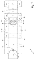
図1〜図6に示されたタバコパッケージ1の容器3、4は、図7及び図8に夫々示された対応ブランク38、39から得られる。ブランク38、39の夫々は多数の要素からなり、これらの要素は、各容器3、4の対応する壁に関して、可能な限り参照番号に等しいアクセント付き参照番号が付けられる。
The
図7を参照するに、内ブランク38は、2本の長手方向折り線40と多数の横断方向折り線41を有し、折り線41は2本の長手方向折り線40の間で、内箱3の前壁9を形成する少なくとも1つのパネル9’と、内箱3の底壁8を形成するパネル8’と、内箱3の後壁10を形成するパネル10’と、蓋6の後壁13を形成するパネル13’と、蓋6の上壁12を形成するパネル12’と、パネル12’のための補強パネル12”と、パネル13’のための補強パネル13”と、パネル10’のための補強パネル10”とを形成する。特に、補強パネル12”はパネル12’の内側に接着され、補強パネル13”はパネル13’上に乗り、補強パネル10”はパネル10’の内側に接着される。
Referring to FIG. 7, the inner blank 38 has two
パネル9’は、内箱3の側壁11の外側部分を形成すると共にパネル9’の両側に位置し、長手方向折り線40によってパネル9’に接続される2枚のウィング11’を有している。パネル10’は、内箱3の側壁11の内側部分を形成すると共にパネル10’の両側に位置し、長手方向折り線40によってパネル10’に接続される2枚のウィング11”を有している。パネル13’は、蓋6の側壁14を形成すると共にパネル13’の両側に位置し、長手方向折り線40によってパネル13’に接続される2枚のウィング14’を有している。パネル10”は、ウィング11”に対応してその内側に糊付けされると共にパネル10”の両側に位置し、長手方向折り線40によってパネル10”に接続される2枚の補強ウィング11’’’を有している。
The
各ウィング11”は、横断方向の折り線41によってウィング11’に接続されると共にウィング11”に対して90度折り畳まれてパネル8’の内面に接着されるタブ42を有する。各ウィング14’は、横断方向の折り線41によってウィング14’に接続されると共にウィング14’に対して90度折り畳まれてパネル12’の内面に接着されるタブ43を有する。
Each
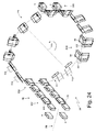
図8を参照するに、外ブランク39は、2本の長手方向折り線44と多数の横断方向折り線45を有し、折り線45は2本の長手方向折り線44の間で、外箱4の前壁17を形成するパネル17’と、外箱4の底壁15を形成するパネル15’と、外箱4の後壁18を形成するパネル18’とを形成する。
Referring to FIG. 8, the outer blank 39 has two
パネル17’は、外箱4の側壁19の外側部分を形成すると共にパネル17’の両側に位置し、長手方向折り線44によってパネル17’に接続される2枚のウィング19’を有している。パネル18’は、外箱4の側壁19の内側部分を形成すると共にパネル18’の両側に位置し、長手方向折り線44によってパネル18’に接続される2枚のウィング19”を有している。
The
各ウィング19”は、横断方向の折り線45によってウィング19’に接続されると共にウィング19”に対して90度折り畳まれてパネル15’の内面に接着されるタブ46を有する。
Each
図9には、上述したタイプであってかつ図1〜図3に示したタバコパッケージ1を生産するタバコ包装機47が示されている。
FIG. 9 shows a
包装機47は、包装されたタバコ群2を生産する包装ユニット48と、包装ユニット48によって受け取られた、包装された対応タバコ群2の周りでブランク38を折り畳むことにより内箱3を生産する次の包装ユニット49と、包装ユニット49によって受け取られた対応内箱3の周りでブランク39を折り畳むことにより外箱4を生産する包装ユニット50と、入力として入力ステーション52に対応して包装ユニット49から内箱3を受けると共に出力として出力ステーション53に対応して包装ユニット50に内箱3を供給する運搬ユニット51とを有する。
The
図10に示すように、包装ユニット49は、多数の包装ポケット55(図18に示す)が設けられた包装コンベヤ54を有しており、各ポケットは内箱38を収容し、S2からS14までの連続した作業ステーション(図11及び図12に示す)を介して入力ステーションS1と出力ステーションS15の間に延びる包装経路P1に沿って、内箱3をステップ毎に(即ち、一連の停止ステップを間に入れた一連の動作ステップから構成される間欠運動を伴った状態で)供給するようになっている。
As shown in FIG. 10, the
入力ステーションS1に対応して、積み重ねられた内ブランク38を収容すると共に底の出口から包装コンベヤ54の包装ポケット55に向けて周期的に内ブランク38を供給するホッパ(図示せず)が設けられる。尚、ホッパの底部出口に対応して配置される各内ブランク38は、底部出口に並んだ入力ステーションS1において停止・待機した状態の、下に横たわる包装コンベヤ54の包装ポケット55に支持されて垂直に移動する吸引把持ヘッドによって拾い上げられる。
Corresponding to the input station S1, there is provided a hopper (not shown) for receiving the stacked
留意すべきことは、包装コンベヤ54は常に横方向に、即ちその横断方向折り線41が送り方向と平行になるように、包装経路P1に沿って各内ブランク38を供給することである。言い換えれば、包装コンベヤ54は、送り方向に対して各内ブランク38の向きを変化させることはせず、包装経路P1のあらゆる地点において、各内ブランク38は常にその横断方向折り線41が送り方向と平行になる(ひいては、それ自身の長手方向折り線40は送り方向に対して垂直となる)。包装経路P1に沿って各内ブランク38の方向性を常に一定に保持することにより、折り畳み作業と包装コンベヤ54の構造の双方を簡素化できる。
It should be noted that the packaging conveyor 54 always feeds each inner blank 38 along the packaging path P1, so that its
図18に示す好ましい実施形態によれば、包装コンベヤ54は2つのエンドプーリ周りに巻き付けられ多数の包装ポケット55を支持するコンベヤベルトから構成されており、従って、包装経路P1は“U”字形をしており、包装経路P1のストレート初期部分に沿って配置された入力ステーションS1と、中間の半円部分を介して真っ直ぐな初期部分に接続された包装経路P1のストレート最終部分に沿って配置された出力ステーションS15との間に延在している。 According to the preferred embodiment shown in FIG. 18, the wrapping conveyor 54 is comprised of a conveyor belt that is wrapped around two end pulleys and supports a number of wrapping pockets 55, so that the wrapping path P1 has a "U" shape. The input station S1 arranged along the straight initial part of the packaging path P1 and the straight final part of the packaging path P1 connected to the straight initial part via the intermediate semicircular part It extends between the output station S15.
図11に示すように、作業ステーションS2では、折り畳み装置56は可動部品(即ち、内ブランク38が作業ステーションS2で待機停止している間に動いて折り畳み処理を実行する部品)を備えて提供される。折り畳み装置56は同時に、パネル13’に対してパネル12’を、ウィング14’に対してタブ43を、同じ横断方向折り線41周りに90度折り畳み、内ブランク38を“L”字状にする。作業ステーションS3では、折り畳み装置57は、一定の折り畳みプロフィール(即ち、可動部品を持たず、内ブランク38が包装経路P1を移動している間に折り畳み作業を実行し、ひいては内ブランク38の送り動作を生かすような折り畳み螺旋)を有して提供される。折り畳み装置57は同時に、パネル13’に対してパネル12’を、ウィング14’に対してタブ43を、同じ横断方向折り線41周りに、作業ステーションS2における折り畳み装置56によってなされた同様の折り畳みとは反対方向に90度折り畳み、再度内ブランク38を“L”字状にする。2つの折り畳み装置56、57は、対応する横断方向折り線41に沿って内ブランク38を屈曲させる(即ち、残留したスプリングバック力をかなり低減するための脆弱化させる)機能を持った、正反対の2つの折り畳み(即ち、互いに相殺させる)作業を実行する。従って、2つの折り畳み装置56、57の機能は、内ブランク38の実際の折り畳みを実行するものではなく、むしろその後の折り畳み作業(後述する)のために内ブランク38を用意するものである。
As shown in FIG. 11, in the work station S2, the
パネル13’に対してパネル12を’、及びタブ43をウィング14’から分割する横断方向折り線41に沿う、上述した内ブランク38の屈曲は、以下に記載の蓋6の適切な形成を可能にするのに非常に有効である。即ち、内ブランク38のこの屈曲無くしては、以下に説明する蓋6の形成が問題となり、その後、(蓋6が奇形することで)廃棄しなければならない不完全な内箱3の著しい増加を決定付ける可能性がある。
Bending of the inner blank 38 described above along the
また、作業ステーションS3では、折り畳み装置58は可動部品(即ち、内ブランク38が作業ステーションS3で待機停止している間に動いて折り畳み処理を実行する部品)を備えて提供される。折り畳み装置58は、作動タブ23を折り線28周りで屈曲させる機能を伴って、パネル9’に対して作動タブ23を折り線28周りに90度折り畳む。
In the work station S3, the
最後に、作業ステーションS3では、パネル9’の上の地点60(図12に示す)に接着剤を置く糊付け装置59が(通常、粘着性接着剤を噴霧するノズルが設けられた状態で)提供される。
Finally, at work station S3, a gluing
作業ステーションS3と作業ステーションS5との間には、折り畳み装置61が、一定の折り畳みプロフィール(即ち、可動部品を持たず、内ブランク38が包装経路P1を移動している間に折り畳み作業を実行し、ひいては内ブランク38の送り動作を生かすような折り畳み螺旋)を有して提供される。その折り畳み装置61は、パネル9’に対して持ち上げタブ29を折り線28周りに180度折り畳む。特に、折り畳み装置61は、作業ステーションS3と作業ステーションS4の間で、パネル9’に対して持ち上げタブ29を折り線28周りに90度折り畳み(即ち、作業ステーションS4において、持ち上げタブ29はパネル9’に対して90度折り畳まれる)、その後折り畳み装置61は、作業ステーションS4と作業ステーションS5の間で、パネル9’に対して持ち上げタブ29を折り線28周りに、(180度全体に対して)追加の90度分を折り畳む(即ち、作業ステーションS5では、持ち上げタブ29はパネル9’に対して180度分、パネル9’それ自身の上へと折り畳まれ、接着剤60の存在効果によって接着される)。
Between the work station S3 and the work station S5, the
作業ステーションS4では、折り畳み装置62は可動部品(即ち、内ブランク38が作業ステーションS4で待機停止している間に動いて折り畳み処理を実行する部品)を備えて提供される。折り畳み装置62は、パネル10”に対して補強ウィング11’’’を、対応する長手方向折り線40周りに90度折り畳み、同時に、接続タブ20の下部分33を、中間部分32に対して横断方向折り線41の周りで180度、中間部分32それ自身の上へと折り畳む。留意すべきことは、折り畳み装置62から下流側において、補強ウィング11’’’はそれらの元の位置へと自由に跳ね返れるようにさせておかれることである。実際、補強ウィング11’’’は必ずしもパネル10”と完全に同一平面の初期位置に戻るわけでなく、(図11に示すように)パネル10”に対して若干傾斜した位置をとる。
In the work station S4, the
作業ステーションS5では、持ち上げタブ29を押圧することで内ブランク38を局部的に平坦化し、持ち上げパネル9’上への再度のタブ29の折り畳みを圧迫する可動部品(即ち、内ブランク38が作業ステーションS5で待機停止している間に動いて押圧処理を実行する部品)を備えて押圧装置63が提供される。
In the work station S5, the inner blank 38 is locally flattened by pressing the
作業ステーションS5と作業ステーションS6との間には回転押圧装置64(即ち、内ブランク38が包装経路P1を移動する間に、回転することで外面を内ブランク38上で“ロール”させる回転ドラムからなるもの)が配置され、接続タブ20の下部分33を押圧することで内ブランク38を局部的に平坦化し、中間部分32上への再度の下部分33の折り畳みを圧迫している。
Between the work station S5 and the work station S6, there is a rotary pressing device 64 (ie, a rotary drum that rotates while the inner blank 38 moves in the packaging path P1 to “roll” the outer surface on the inner blank 38). The inner blank 38 is locally flattened by pressing the
作業ステーションS6では、折り畳み装置65が可動部品(即ち、内ブランク38が作業ステーションS6で待機停止している間に動いて折り畳み処理を実行する部品)を備えて提供される。その折り畳み装置65は、パネル9’に対して作動タブ23を、折り線28周りにパネル9’それ自体の上に90度折り畳む。
In the work station S6, a
作業ステーションS6では、持ち上げタブ29を押圧することで内ブランク38を局部的に平坦化し、パネル9’の内壁への再度の持ち上げタブ29の折り畳みを圧迫する可動部品(即ち、内ブランク38が作業ステーションS6で待機停止している間に動いて押圧処理を実行する部品)を備えて押圧装置66が提供される。
In the work station S6, the inner blank 38 is locally flattened by pressing the
作業ステーションS7と作業ステーションS8との間には回転押圧装置67(即ち、内ブランク38が包装経路P1を移動する間に、回転することによって内ブランク38上で外面を“ロール”させる回転ドラムからなるもの)が配置され、持ち上げタブ29と作動タブ23を押圧することで内ブランク38を局部的に平坦化し、パネル9’上への持ち上げタブ29と作動タブ23の再度の折り畳みを圧迫している。
Between the work station S7 and the work station S8, there is a rotary pressing device 67 (i.e., a rotary drum that "rolls" the outer surface on the inner blank 38 by rotating while the inner blank 38 moves in the packaging path P1). The inner blank 38 is locally flattened by pressing the
作業ステーションS9では、パネル12’とタブ43とウィング11”の上の地点69(図12に示す)に接着剤を置く糊付け装置68が(通常、粘着性接着剤を噴霧するノズルが設けられた状態で)提供される。
At work station S9, there is a gluing device 68 (usually provided with a nozzle for spraying adhesive adhesive) that places the adhesive at a point 69 (shown in FIG. 12) on the
折り畳み手段は、内ブランク38を折り畳んでヒンジ結合された蓋6を形成する。上記の折り畳み手段は、蓋6の形成中において、少なくとも1つの補強パネルを少なくとも第1パネル10’の上に重ね合わせる。特に、内ブランク38の実施例では、第1折り畳み手段は、蓋6の形成中において、少なくとも補強パネル10”を少なくとも第1パネル10’の上に重ね合わせる。さらに、折り畳み手段は、蓋6とは異なる内ブランク38の他の部分を平坦のままにして蓋6を形成する。
The folding means folds the inner blank 38 to form the hinged
以下により詳細に記載するように、上記の折り畳み手段は、好ましくは、いくつかの折り畳み手段70、71、72、73を備える。 As will be described in more detail below, the folding means preferably comprises a number of folding means 70, 71, 72, 73.
作業ステーションS9と作業ステーションS10の間には、折り畳み装置70が、一定の折り畳みプロフィール(即ち、可動部品を持たず、内ブランク38が包装経路P1を移動している間に折り畳み作業を実行し、ひいては内ブランク38の送り動作を生かすような折り畳み螺旋)を有して提供される。その折り畳み装置70は、パネル12’に対してパネル12”を、対応する横断方向折り線41周りに90度折り畳む。
Between the work station S9 and the work station S10, a
作業ステーションS10では、折り畳み装置71が可動部品(即ち、内ブランク38が作業ステーションS10で待機停止している間に動いて折り畳み処理を実行する部品)を備えて提供される。折り畳み装置71は初めは、ウィング14’に対してタブ43を、対応する横断方向折り線41周りに90度折り畳み、次いで同じ時間に(即ち、一緒に)ウィング14’をパネル13’に対して、対応する長手方向折り線40周りに90度折り畳み、パネル12’をパネル13’に対して、対応する横断方向折り線41周りに90度折り畳み(このようにして、タブ43はパネル12’の上に横たわり、接着剤69のあることによる効果により接着される)、パネル12”をパネル12’に対して、対応する横断方向折り線41周りに90度折り畳み、そしてパネル13”をパネル12”に対して、対応する横断方向折り線41周りに90度折り畳む。
In the work station S10, a
作業ステーションS10と作業ステーションS11の間には、折り畳み装置72が、一定の折り畳みプロフィール(即ち、可動部品を持たず、内ブランク38が包装経路P1を移動している間に折り畳み作業を実行し、ひいては内ブランク38の送り動作を生かすような折り畳み螺旋)を有して提供される。その折り畳み装置72は、パネル12”に対してパネル13”を、対応する横断方向折り線41周りに、作業ステーション10で折り畳み装置71によってなされた同様の折り畳みとは反対の方向に90度折り畳む。2つの折り畳み装置71、72は、2枚のパネル12”、13”間で、対応する横断方向折り線41に沿って内ブランク38を屈曲させる(或いは、残留したスプリングバック力をかなり低減するために脆弱化させる)機能を有した、正反対の2つの折り畳み(即ち、互いに相殺させる)作業を実行する。
Between the work station S10 and the work station S11, a folding device 72 performs a folding operation while having a certain folding profile (i.e. no moving parts and the inner blank 38 is moving in the packaging path P1, As a result, it is provided with a folding helix that makes use of the feeding operation of the inner blank 38. The folding device 72 folds the
作業ステーションS11では、折り畳み装置73が可動部品(即ち、内ブランク38が作業ステーションS11で待機停止している間に動いて折り畳み処理を実行する部品)を備えて提供される。その折り畳み装置73は、同時に(即ち、一緒に)パネルグ12”をパネル12’に対して、対応する長手方向折り線41周りに90度折り畳み(このようにして、パネル12”はパネル12’の上に横たわり、接着剤69の存在により接着される)、パネル13”をパネル12”に対して、対応する横断方向折り線41周りに90度折り畳む(このようにして、パネル13”はパネル13’の上に横たわり、パネル10”はパネル10’の上に横たわり、接着剤69の存在により接着され、ウィング11’’’は休止することなくウィング11”と重なる。尚、次の作業ステーションでは、ウィング11’’’は接着剤69の存在によりウィング11”に接着されることになる)。
In the work station S11, the
作業ステーションS12では、パネル10”を押圧することで内ブランク38を局部的に平坦化し、パネル10’上への再度のパネル10”の折り畳みを圧迫する可動部品(即ち、内ブランク38が作業ステーションS12で待機停止している間に動いて押圧処理を実行する部品)を備えて押圧装置74が提供される。
In the work station S12, the inner blank 38 is locally flattened by pressing the
作業ステーションS13では、先の押圧装置74と同一の押圧装置75が設けられ、その装置には、パネル10”を押圧することで内ブランク38を局部的に平坦化し、パネル10’上への再度のパネル10”の折り畳みを圧迫する可動部品(即ち、内ブランク38が作業ステーションS13で待機停止している間に動いて押圧処理を実行する部品)が設けられる。
In the work station S13, the same pressing device 75 as the previous
図13に示すように、折り畳み装置62は、平行6面体形状の2つの側方折り畳み体76と、包装経路P1に直交する垂直作業方向D1に沿って周期的に動くように同じキャリッジ上に据え付けられた“U”字状の中央折り畳み体77とを有する。更に、折り畳み装置62は、平行6面体形状の2つのコントラスト体78と、包装経路P1と垂直作業方向D1の双方に直交する水平作業方向D2に沿って周期的に動くように同じキャリッジ上に据え付けられた中央コントラスト体77とを有する。使用時、2つの側方折り畳み体76は垂直作業方向D1に沿って上から下へと移動し、パネル10”に対して補強ウィング11’’’を、対応する長手方向折り線40周りに90度折り畳む。尚、このステップでは、2つの側方折り畳み体76に対してコントラスト性を与えるため、2つのコントラスト体78はパネル10”の下方にあって、長手方向折り線40に近いパネル10”の両側に配置されている。2つの側方折り畳み体76のそのアクションと同時に、折り畳み体77は垂直作業方向D1に沿って下方に移動し、接続タブ20の下部分33を中間部分32に対して横断方向折り線41周りに90度折り畳む。尚、このステップでは中央コントラスト体79は、折り畳み体76に対してコントラスト性を与えるために、接続タブ20に対応してパネル10の下方に配置される。折り畳み体76、77が垂直作業方向D1に沿って下方に移動した後は、コントラスト体78、79は水平作業方向D2に沿って一緒に移動する。補強ウィング11’’’の軌跡から移動し、ひいては包装経路P1に沿うその後の内ブランク38の送りを可能にするために、2つのコントラスト体78は水平作業方向D2に沿って移動する一方で、接続タブ20の下部分33を中央部分32に対して横断方向折り線41周りに更に90度折り畳み(即ち、全部で180度)、部分33を中間部分32それ自体の上に折り畳むべく、中央コントラスト体79は水平作業方向D2に移動する。
As shown in FIG. 13, the
図14に示すように、折り畳み装置65は、関節でつながった四角形体81によって支持されて包装経路P1に対して垂直を成す折り畳みロト並進運動を実行する折り畳み体80を有する。
As shown in FIG. 14, the
図15に示すように、折り畳み装置71は、“L”字状の断面を有しかつ水平作業方向D2(包装経路P1に垂直)に移動可能な折り畳み体82を有する。更に折り畳み装置71は折り畳み体83を備え、折り畳み体83は、中央折り畳み部材84と、中央折り畳み部材84の両側に配置された2つの上部側方部材85と、同様に中央折り畳み部材84の両側に配置された2つの下部側方部材86とを有する。折り畳み装置71は、(包装経路P1及び水平作業方向D2の両方に垂直である)垂直な作業方向D1に移動可能であり、加えて、中央部材84と2つの上部側方部材85と2つの下部側方部材86は垂直方向(即ち、作業方向D1に沿って)異なる位置に配置され、折り畳み体83が連続した動作を伴って垂直方向(即ち、作業方向D1に沿って)に移動している間に、内ブランク38の連続した各折りを実行するようになっている。最後に、折り畳み装置71はコントラスト体87を有する。好ましくは、コントラスト体87は、鍬形の中央部材88と、中央部材88の両側に配置された2つの側方突起89とを有し、包装経路P1に平行な回転軸線90の周りを回転するように据え付けられる。
As shown in FIG. 15, the
使用中、内ブランク38が作業ステーションS10で停止すると、コントラスト体は回転軸線90周りに回転し、2つの側方突起89をウィング14’の上方でかつタブ43近くに配置し、折り畳み体83の上部側方部材85に対してコントラスト性を成し、その後、折り畳み体83は、2つの上部側方部材85がタブ43をウィング14’に対し、対応する横断方向折り線41周りに90度折り畳むように、下から垂直作業方向D1上方に移動する。その後は、コントラスト体87は回転軸線90周りで逆方向に回転し、2つの突起89をウィング14’から取り外し、同時に中央部材88をパネル13’上に置いて折り畳み体33の中央部材84に対してコントラスト性を成し、その後、2つの下部側方部材86がウィング14’をパネル13’に対し、対応する長手方向折り線40周りに90度折り畳むと同時に、中央部材84がパネル12’をパネル13’に対して、対応する横断方向折り線41周りに90度折り畳むように、折り畳み体83は垂直作業方向D1に沿って更に上方に移動する(このようにして、タブ43はパネル12’の上に横たわり、接着剤69の存在により接着される)。最後に、折り畳み体82は水平作業方向D2にコントラスト体87に向かって移動し、パネル12”をコントラスト体87上へとパネル12’に対して90度折り畳み、パネル13”をパネル12’に対して、対応する横断方向折り線41周りに90度折り畳む。
In use, when the inner blank 38 is stopped at the work station S10, the contrast body rotates around the
図16に示すように、折り畳み装置73は、垂直作業方向D1(包装経路P1に垂直)に移動可能な折り畳み体91と、傾斜作業方向D3(垂直作業方向D1にも、水平作業方向D2にも、包装経路P1にも平行でない)に移動可能な心合せ体92とを有する。使用中、内ブランク38が作業ステーションS11で停止すると、折り畳み体91は垂直作業方向D1に沿って下方に移動し、パネル12”をパネル12’に対して、対応する横断方向折り線41周りに90度折り畳み(このようにして、パネル12”はパネル12’の上に横たわり、接着剤69の存在により接着される)、同時にパネル13”をパネル12”に対して、対応する横断方向折り線41周りに90度折り畳む(このようにして、パネル13”はパネル13’の上に横たわり、接着剤69の存在により接着され、ウィング11’’’は一気にウィング11”と重なる。尚、次の作業ステーションでは、ウィング11’’’は接着剤69の存在によりウィング11”へと接着されることになる)。その後、心合せ体92は傾斜作業方向D3を下方に移動し、パネル10”の端縁部を押え付ける。
As shown in FIG. 16, the
好ましい実施形態によれば、図17により良く示されているように、パネル12”がパネル12’に対して90度折り畳まれ、同時にパネル13”が折り畳み体91のパネル12”に対して90度折り畳まれた際には、(パネル10”が完全にその下のパネル10’の上にある間に)ウィング11’’’はその下にあるウィング11”に対して少し持ち上げられた状態に保持され、特にパネル10”の端縁部の上にあってこれを押圧する心合せ体92の働きによって、ウィング11’’’はその下にあるウィング11”に対して少し持ち上げられたままとなる。このようにして、包装経路P1の中、作業ステーションS11から下流側で作業ステーションS12に向かう内ブランク38のその後の送りにおいて、折り畳み体91が垂直作業方向D1の下から上へ移動する間に、心合せ体92はパネル10”の端縁部が低められたまま押え付けることができ、パネル10”、13”を、それらに対応して下にあるパネル10’、13’に対面する正規位置に保持することができ、パネル12”がその下にあるパネル12’上に押圧された状態を保持することができる。
According to a preferred embodiment, as better shown in FIG. 17, the
折り畳み装置62が補強ウィング11’’’を90度折り畳み、その後折り畳み装置62の下流側で補強ウィング11’’’が自由な状態にセットされるという事実は、補強ウィング11’’’がその下にあるウィング11”に対して若干持ち上げられたままの状態になるという事実を促進している。
The fact that the
包装経路P1から下流に配置された作業ステーションでは、ウィング11’’’はウィング11”上に押圧され、パネル10’に対するウィング11’の、対応する長手方向折り線40周り90度の折りと同時に、接着剤69によるウィング11’’’とウィング11”との間の接着が完了する。言い換えるならば、ウィング11”がパネル10’に対して垂直な位置にある時にウィング11’’’はウィング11”に接着されるのであって、包装経路P1に沿ってウィング11”は常時パネル10’と同一平面上にあるため、このことは包装経路P1の作業ステーションでは起こり得ない。
At the work station arranged downstream from the packaging path P1, the
図10に示すように、包装ユニット49は、多数の包装ポケット94(図19に概略的に示す)が設けられた包装コンベヤ93を有しており、それらポケットの夫々は内ブランク38と、それに対応して包装されたタバコ群2を収容し、内ブランク38と包装タバコ群2を、入力ステーションS16と出力ステーションS18の間に延びる包装経路P2に沿って給送するようになっている。
As shown in FIG. 10, the
入力ステーションS16では、部分的に予め折り畳まれて包装コンベヤ54から来る内ブランク38が包装ポケット94に供給され、内ブランク38それ自体を更に折り畳む。入力ステーションS16と出力ステーションS18との間に配置された供給ステーションS17に対応して、包装されたタバコ群2は、先に供給されている内ブランク38に結合されるべき包装ポケット94の内部に供給される。具体的には、包装されたタバコ群2の後壁は内ブランク38のパネル10’上に横たわる。出力ステーションS18では、内箱3(包装タバコ群2の周りで内ブランク38を折り曲げることにより形成される)は包装ポケット94から抽出されて、包装ユニット50に向かって進む。出力ステーションS18の下流側には、内箱3を包装ユニット50に搬送する乾燥コンベヤが配置される(図9に概略的に示す)。
At the input station S16, the inner blank 38, which is partially pre-folded and comes from the packaging conveyor 54, is supplied to the
さらなる折り畳み手段が、第1パネル10’の周りで内ブランク38を折り畳み、内ブランク38に第1パネル10’の周りのカップ形状を与える。以下により詳細に記載するように、上記の折り畳み手段は、好ましくは、折り畳み装置95によって構成される。それゆえ、上記の供給ステーションS17は、折り畳み装置95よりも下流側に配置される。特に、折り畳み装置95は折り畳み装置70、71、72、73と供給ステーションS17の間に配置される。
Further folding means folds the inner blank 38 around the first panel 10 'and gives the inner blank 38 a cup shape around the first panel 10'. As will be described in more detail below, the folding means is preferably constituted by a
図19に示すように、入力ステーションS16には折り畳み装置95が配置され、内ブランク38のタブ42をウィング11”に対して90度折り畳み、次いで包装ポケット94内に内ブランク38を挿入することによって、パネル10’に対するパネル8’の90度の折り畳みと、パネル10’に対する2枚のウィング11”の90度の折り畳みを決定する。言い換えるならば、タブ42を90度折り畳んだ後、包装ポケット94内の内ブランク38の入力が、パネル10’に対するパネル8’の90度の折り畳みと2枚のウィング11”の90度の折り畳みを決定し、このようにしてタブ42がパネル8’の上に横たわる。
As shown in FIG. 19, a
供給ステーションS17と出力ステーションS18の間には、折り畳み装置96が配置されてパネル8’に対してパネル9 ’を、対応する横断方向折り線41周りに90度折り畳む。内ブランク38の折り畳みは、包装ポケット94からの内箱3の抽出と同時に出力ステーションS18で完了する。尚、包装ポケット94からの内箱3の抽出中に、折り畳み装置97はウィング11’をパネル9’に対してウィング11”上へと、対応する長手方向折り線40周りに90度折り畳み、内箱3の側壁11の形成を完了する。尚、好ましくは、糊付け装置(図示せず)が折り畳み装置97のすぐ上流側に配置され、ウィング11”の折り畳み直前にウィング11’とウィング11”の間に接着剤を付ける。
Between the supply station S17 and the output station S18, a
図19に示す好ましい実施形態によれば、供給ステーションS17の上流側には、供給ステーションS17で各包装タバコ群2が内ブランク38内へと一層容易に挿入することができるように、各内ブランク38の蓋6を、対応するヒンジ7周りで回転させることによって蓋6をその閉じ位置から開き位置に移動させる開放装置98が配置される。尚、具体的に言えば、供給ステーションS17では、包装されたタバコ群2は内ブランク38内への実質的な軸方向(又は長手方向の)動きを伴って挿入することができる。このため、供給ステーションS17の下流側には、外ブランク39の折り畳みを続行する前に各内ブランク38の蓋6を、対応するヒンジ7周りで回転させることによって蓋6をその開き位置から閉じ位置に移動させる閉鎖装置99が配置される。
According to the preferred embodiment shown in FIG. 19, each inner blank is arranged upstream of the supply station S17 so that each wrapping
それゆえ、最初に、内箱3の蓋6が形成される。この蓋の形成中において、内ブランク38の端部に対応しかつ蓋6を形成するように設計されたパネルに隣接するパネルによって規定される、少なくとも1つの補強パネルは、内箱3の後壁10を形成するパネル10’に重ね合わせられ(場合により、接着され)る。内ブランク38を折り畳むさらなるステップは、内ブランク38にカップ形状を与える。最後に、形成された蓋6の開閉によって、包装されたタバコ群2を、部分的に既に形成された、少なくとも内箱3の後壁10の補強パネル10”にわたって挿入することができ、あるいは、実現不可能である。
Therefore, first, the
開放装置98は、好ましくは、折り畳み装置95と供給ステーションS17の間において、配置されている。
The
添付図面に示す好ましい実施形態によれば、包装コンベヤ93は、水平に配置された回転の中心軸線100の周りで段階的に回転する回転ホイールによって構成される。従って、入力ステーションS16から出力ステーションS18に延びる包装経路P2は円形である。
According to a preferred embodiment shown in the accompanying drawings, the
図10に示すように、包装ユニット49は、予め折り畳まれた内ブランク38を包装コンベヤ5の出力ステーションS15から包装コンベヤ93の入力ステーションにS16へと搬送する搬送コンベヤ101を有する。搬送コンベヤ101に沿って包装コンベヤ93の上流側には、内ブランク38のタブ42とパネル8’の間に接着剤を付ける糊付け装置102が配置される。
As shown in FIG. 10, the
好ましい実施形態によれば、包装経路P1の入力ステーションS1では一度に1枚の内ブランク38が包装コンベヤ54に供給され、搬送コンベヤ101は一度に2枚の内ブランク38を包装コンベヤ54から包装コンベヤ93に搬送する。尚、この実施形態では、包装コンベヤ93は各ステップで一度に2枚の内ブランク38を処理する。これに代わる実施形態としては、図示しないが、包装経路P1の入力ステーションS1において一度に2枚の内ブランク38が包装コンベヤ54に供給される。
According to a preferred embodiment, at the input station S1 of the packaging path P1, one inner blank 38 is supplied to the packaging conveyor 54 at a time, and the
図20に示すように、包装ユニット50は、多数の包装ポケット104(図23に示す)が設けられた包装コンベヤ103を有しており、それらポケットの夫々は、外ブランク39を収容して、S20からS32への一連の作業ステーションを介して入力ステーションS19と出力ステーションS33の間に延びる包装経路P3(図21、図22に示す)に沿って段階的に(即ち、対応する一連の停止状態を間に挟む一連の動作状態によって構成される断続的動作を伴って)外ブランク39を送るようになっている。
As shown in FIG. 20, the
入力ステーションS19には、積み重ねられた外ブランク38を収容すると共に底の出口から包装コンベヤ103の包装ポケット104に向けて周期的に外ブランク39を供給するホッパ(図示せず)が設けられる。具体的には、ホッパの底部出口に配置される各外ブランク39は、底部出口に並んで停止・待機した状態にある包装コンベヤ103の包装ポケット104の上に横たわって垂直に移動する吸引把持ヘッドによって拾い上げられる。
The input station S19 is provided with a hopper (not shown) that accommodates the stacked
留意すべきことは、包装コンベヤ103は常に横方向に、或いは常にその横断方向折り線45が送り方向と平行になるように、包装経路P3に沿って各外ブランク39を前進させることである。言い換えれば、包装コンベヤ103は、送り方向に対して各外ブランク39の向きを変化させることはせず、包装経路P3のあらゆる地点において、各外ブランク39は常にその横断方向折り線45が送り方向と平行になる(ひいては、それ自身の長手方向折り線44は送り方向に対して垂直となる)。包装経路P3に沿って各外ブランク39の方向性を常に一定に保持することにより、折り畳み作業と包装コンベヤ103の構造双方を簡素化できる。
It should be noted that the wrapping
図23に示す好ましい実施形態によれば、包装コンベヤ103は2つのエンドプーリ周りに巻き付けられ多数の包装ポケット55を支持するコンベヤベルトから構成されている。従って、包装経路P3は“U”字形をしており、直線的な包装経路P3の初期部分に沿って配置された入力ステーションS19と、中間の半円部分を介して真っ直ぐな初期部分に接続された直線的な包装経路P3の最終部分に沿って配置された出力ステーションS33との間に延在している。
According to the preferred embodiment shown in FIG. 23, the
図21に示すように、作業ステーションS21では、折り畳み装置105は可動部品(即ち、外ブランク39が作業ステーションS21で待機停止している間に動いて折り畳み処理を実行する部品)を備えて提供される。折り畳み装置105は同時に、接続タブ37に対して突起37’を、対応する横断方向折り線45周りに、パネル18’に対して接続タブ37を、対応する横断方向折り線45周りに、パネル17’に対してシーリングタブ22を、対応する横断方向折り線45周りに夫々、90度折り畳む。
As shown in FIG. 21, in the work station S21, the
作業ステーションS22では、折り畳み装置106は、一定の折り畳みプロフィール(即ち、可動部品を持たず、外ブランク39が包装経路P3を移動している間に折り畳み作業を実行し、ひいては外ブランク39の送り動作を生かすような折り畳み螺旋)を有して提供される。折り畳み装置106は、パネル18’に対して同時に接続タブ37を、対応する横断方向折り線45周りに更に90度(合計180度に対して)折り畳み、接続タブ37をパネル18’の上に置き、更にパネル17’に対してシーリングタブ22を、対応する横断方向折り線45周りに折り畳み、パネル17’上にシーリングフラップ22を置く。
In the work station S22, the
作業ステーションS23と作業ステーションS25との間には、折り畳み装置107が、一定の折り畳みプロフィール(即ち、可動部品を持たず、外ブランク39が包装経路P3を移動している間に折り畳み作業を実行し、ひいては外ブランク39の送り動作を生かすような折り畳み螺旋)を有して提供される。折り畳み装置107は、パネル17’に対してシーリングタブ22を180度、折り畳み装置105、106によって実行された先の折り畳みとは反対方向に折り畳む。折り畳み装置107と、(シーリングタブ22に作用する際の)2つの折り畳み装置105、106とは、対応する横断方向折り線45に沿って外ブランク39を屈曲させる(即ち、残留したスプリングバック力をかなり低減するために脆弱化させる)機能を有した、正反対の2つの折り畳み(即ち、互いに相殺させる)作業を実行する。従って、折り畳み装置107、106及び107(シーリングタブ22に作用する際の)の機能は、外ブランク39の実際の折り畳みを実行するものではなく、むしろそれに続く折り畳み作業(後述する)のために外ブランク38を用意するものである。
Between the work station S23 and the work station S25, the
作業ステーションS26では、折り畳み装置108は可動部品(即ち、外ブランク39が作業ステーションS26で待機停止している間に動いて折り畳み処理を実行する部品)を備えて提供される。折り畳み装置108は、シーリングタブ22に対して接続タブ26を、対応する横断方向折り線45周りに90度折り畳む。
In the work station S26, the
作業ステーションS27では、折り畳み装置109が、一定の折り畳みプロフィール(即ち、可動部品を持たず、外ブランク39が包装経路P3を移動している間に折り畳み作業を実行し、ひいては外ブランク39の送り動作を生かすような折り畳み螺旋)を有して提供される。折り畳み装置109は、シーリングタブ22に対して接続タブ26を、対応する横断方向折り線45周りに更に90度(合計180度に対して)折り畳み、接続タブ26をシーリングタブ22の上に置く(ひいては、作動タブ24をパネル17’上に置く)。
In the work station S27, the
作業ステーションS29には、回転押圧装置110(即ち、内ブランク38が包装経路P3を移動する間に、回転することで内ブランク38上で外面を“ロール”する回転ドラムからなるもの)が配置され、接続タブ26を押圧することで外ブランク39を局部的に平坦化し、シーリングタブ22’上への接続タブ26の再度の折り畳みを圧迫している。
In the work station S29, a rotary pressing device 110 (that is, a rotary drum that "rolls" the outer surface on the inner blank 38 by rotating while the inner blank 38 moves in the packaging path P3) is disposed. The outer blank 39 is locally flattened by pressing the
図20に示すように、包装ユニット50は、多数の包装ポケット112(図24に概略的に示す)が設けられた包装コンベヤ111を有しており、各ポケットは外ブランク39とそれに対応する内箱3を収納し、入力ステーションS34と出力ステーションS36の間に延びる包装経路P4に沿って、外ブランク39と内箱3を供給するようになっている。
As shown in FIG. 20, the
入力ステーションS34では、部分的に予め折り畳まれて包装コンベヤ103から来る外ブランク39が包装ポケット112に供給され、外ブランク39それ自体を更に折り畳む。入力ステーションS34と出力ステーションS36との間に配置された供給ステーションS35では、内箱3は、先に供給されている外ブランク39に結合されるべき包装ポケット112の内部に供給される。具体的には、内箱3の後壁10は外ブランク39のパネル18’に横たわる。出力ステーションS36では、外箱4(内箱3の周りで外ブランク39を折り曲げることにより形成される)は殆ど完全充分な形で包装ポケット112から抽出されて、更なる包装経路P5とそれに続く乾燥経路P6に沿って進み、包装コンベヤ111の下流側に配置された2つ以上の作動ステーションS37,S38を通過する。乾燥経路P6は包装機47の出口に向かって外箱4を搬送する乾燥コンベヤ(図9に概略的に示す)によって形成される。
In the input station S34, the outer blank 39, which is partially pre-folded and comes from the
図24に示すように、入力ステーションS34には折り畳み装置113が配置され、外ブランク39のタブ46をウィング19”に対して90度折り畳み、次いで包装ポケット112内に外ブランク39を挿入することによって、パネル18’に対するパネル15’の90度の折り畳みと、パネル18’に対する2枚のウィング19”の90度の折り畳みを決定する。言い換えるならば、タブ46を90度折り畳んだ後、包装ポケット112内の外ブランク39の入力が、パネル18’に対するパネル15’と2枚のウィング19”の90度の折り畳みを決定し、このようにしてタブ46がパネル15’の上に横たわる。
24, a
供給ステーションS35と出力ステーションS36の間には、折り畳み装置114が配置されてパネル15’に対してパネル17 ’を、対応する横断方向折り線51周りに90度折り畳む。外ブランク39の折り畳みは、包装ポケット112からの外箱43の抽出の後で(即ち、出力ステーションS18の下流側)作動ステーションS37で完了する。尚、作動ステーションS37では、折り畳み装置115はパネル17’に対してウィング19’をウィング19”上へと対応する長手方向折り線44周りに90度折り畳み、外箱4の側壁19の形成を完了する。尚、好ましくは、糊付け装置(図示せず)が折り畳み装置115のすぐ上流側に配置され、ウィング19”の折り畳み直前にフランジ19’とフランジ19”の間に接着剤を付ける。
A
添付図面に示す好ましい実施形態によれば、包装コンベヤ111は、水平に配置された回転の中心軸線116の周りで段階的に回転する回転ホイールによって構成される。従って、入力ステーションS34から出力ステーションS36に延びる包装経路P4は円形である。包装経路P5とその後の乾燥経路P6は長方形であり、互いに垂直に配置される。
According to a preferred embodiment shown in the accompanying drawings, the
図20に示すように、包装ユニット50は、予め折り畳まれた外ブランク39を包装コンベヤ103の出力ステーションS33から包装コンベヤ111の入力ステーションにS34へと搬送する搬送コンベヤ117を有する。搬送コンベヤ119に沿って包装コンベヤ111の入力ステーションS34の上流側には、外ブランク39のタブ46とパネル15’の間に接着剤を付ける糊付け装置118が配置される。
As shown in FIG. 20, the
好ましい実施形態によれば、包装経路P3の入力ステーションS19では一度に1枚の外ブランク39が包装コンベヤ103に供給され、搬送コンベヤ117は一度に2枚の外ブランク39を包装コンベヤ103から包装コンベヤ111に搬送する。尚、この実施形態では、包装コンベヤ111は各ステップで一度に2枚の外ブランク39を処理する。これに代わる実施形態としては、図示しないが、包装経路P3の入力ステーションS19において一度に2枚の外ブランク39が包装コンベヤ103に供給される。
According to a preferred embodiment, at the input station S19 of the packaging path P3, one outer blank 39 is supplied to the
図20に示すように、作業ステーションS38ではイタリア国特許出願第BO2011A000632号に記載されたタイプの折り畳み装置119が配置されている。内箱3周りでの外ブランク39の折り畳み時には、シーリングタブ22が外箱4の前壁17と同一平面上になるような初期位置にシールタブ22を残すように、シールタブ22は屈曲されない。言い換えるならば、外箱4が作業ステーションS38に入る際には、シーリングタブ22は外箱4の前壁17と同一平面上にある。折り畳み装置119は、内箱3と外箱4との間のスライド動作により、外箱4から内箱3を部分的に引き出し、続いて折り畳み装置119は、シーリングタブ22を、対応する横断方向折り線45周りで内箱3に向かって90度折り畳み、シーリングタブ22を内箱3の蓋6の上壁12の下の作業位置に配置し、最終的には折り畳み装置119は、内箱3と外箱4との間のスライド動作により、内箱3を外箱4内に完全に挿入する。折り畳み装置119の動作の詳細については、イタリア国特許出願第BO2011A000632号に記載されたものを参照されたい。
As shown in FIG. 20, a
図7及び図8に示す好ましい実施形態によれば、ブランク38,39は、ブランク38、39の側方外周(即ち、ウィング11”、19”に対応して)に配置された窓120を通じた位置合わせを示しており、それらの窓は、ブランク38、39それ自体が包装コンベヤ54、103の、対応する包装ポケット55、104に挿入された際、ブランク38、39の適当な長手方向位置合わせを確実にする機能を有している。言い換えるならば、包装コンベヤ54、103の包装ポケット55、104は、ブランク38、39が、対応する包装ポケット55、104内に挿入された際に、ネガ的に位置合わせ窓120の形状を再生すると共に位置合わせ窓120の中に挿入される基準体を有する。このようにして、対応する包装ポケット55、104内でのブランク38、39の正確な長手方向位置合わせが保証される。
According to the preferred embodiment shown in FIGS. 7 and 8, the
図25には、図8に示された外側ブランク39に対し、位置合わせ窓120の形状と位置を異ならせた外ブランク39の変形例が示されている。ここで留意すべきことは、位置合わせ窓120は側壁11、19の内側部分を構成するウィング11”、19”に形成されているということである。尚、その後、位置合わせ窓120は内箱3と外箱4では見ることはできない(即ち、ウィング11”、19”によって覆われる)。
FIG. 25 shows a modification of the outer blank 39 in which the shape and position of the
ユーザが外箱4に対して内箱3をスライドする(図2)のに必要な推力を付与できるようになっている外ブランク39のウィング19’の貫通窓21は、外ブランク39の、対応するウィング19”の位置合わせ窓120によって規制されるものであってはいけない。換言すれば、図8及び図25に示すように、貫通窓21に対面する位置合わせ窓120は貫通窓21それ自体よりも大きな寸法を持たなければならない。
The through
上述した包装方法及びそれに対応する包装機4には多くの利点がある。何故なら、それらは高い品質水準を維持しつつ高い生産性を以て(即ち、単位時間当たりのパッケージ1の多さを以て)ヒンジ式蓋付きスライドオープンパッケージ1の生産を可能ならしめているからである。このような結果は、包装コンベヤ54内で蓋6の形成を完了することにより(即ち、内ブランク38を包装タバコ群2と対にする前に)、蓋6を単純かつ効率の良い方法で形成することを可能すると同時に、包装タバコ群2周りでの内ブランク38の折り畳みをかなり簡素化できる包装ユニット49の形態によって得られるものである。具体的には、真っすぐな包装経路(まさに、包装コンベヤ54の包装経路P1がそうであるように)に沿って蓋6の形成が平易(これにより簡単かつ迅速)である一方で、包装タバコ群2の周りでの内ブランク38の折り畳みが環状の包装経路(まさに、包装コンベヤ93の包装経路P2がそうであるように)に沿って平易(これにより簡単かつ迅速)である。従って、その包装ユニット49の形態のおかげで、全ての折り畳み作業が最も好ましい状況で実行でき、高い品質水準を維持したまま迅速に(即ち、高い生産性の包装工程を以て)実行可能である。
The packaging method described above and the
加えて、それに劣らず大切なことは、上述した包装方法及びそれに対応する包装機47はかなりの“柔軟性”があり、即ち、(内ブランク38又は外ブランク39に含まれるヒンジ式蓋6を伴って、或いはヒンジ式蓋無しの状態で)生産されるスライドオープン式タバコパッケージの種類を非常に迅速かつ簡単に変更できるということである。とりわけ、その高い柔軟性は、各包装ユニット49又は50に、内ブランク38又は外ブランク39の予備折り畳みが実行される第1包装コンベヤ54又は103と、内ブランク38又は外ブランク39の予備折り畳みが完了される第2包装コンベヤ93又は111とがあるという事実によってもたらされる。実際、第1包装コンベヤ54又は103があるために、内ブランク38又は外ブランク39の予備折り畳みを実行して蓋を形成することが比較的単純であり、一旦蓋が形成されたならば内ブランク38又は外ブランク39の最終的な折り畳みは“従来通り”であり(即ち、標準的なブランクの折り畳みに類似)、特段面倒な事態も生じない。
In addition, no less important than that, the packaging method described above and the corresponding
最後に、2つの包装ユニット49、50は互いに非常に類似していることを注意することが重要である。即ち、包装ユニット49、50の双方は、コンベヤベルトにあってブランクの予備的な折り畳みを生成するための第1包装コンベヤ(包装コンベヤ54、103)と、ホイール内にあって中身の周りで(既に部分的に折り畳まれた)ブランクを折り畳むための第2包装コンベヤ(包装コンベヤ93、111)と、2つの包装コンベヤを接続する搬送コンベヤ(搬送コンベヤ101、117)とを有する同一構造を備える。更に、2つの包装ユニット49、50の2つの第2包装コンベヤ(包装コンベヤ93、111)は、同じ方法かつ同じ領域でほぼ全ての包装作業を実行する。最後に、2つの包装ユニット49、50は、互いの間で多数の構成部品を共有することが可能であり、即ち同一の構成要素が双方の包装ユニット49、50で度々存在する(具体的には、2つの包装ユニット49、50は共通して構成要素の少なくとも70〜80%を有することができる)。このように、包装機47の製造、組立、保守コストを顕著な形で打破することが可能である。
Finally, it is important to note that the two
Claims (13)
前記内箱(3)は、1つの開口上端部(5)を有してカップ状であると共に蓋(6)が設けられ、該蓋は内箱(3)それ自体に対して前記開口上端部(5)の開き位置と閉じ位置との間で回転するようにヒンジ(7)に沿って内箱(3)の後壁(10)にヒンジ結合され、
前記内ブランク(38)は、2本の長手方向折り線(40)と多数の横断方向折り線(41)を有し、該横断方向折り線は、前記2本の長手方向折り線(40)との間で、内箱(3)の後壁(10)を形成する少なくとも第1パネル(10’)と、内箱(3)の前壁(9)を形成する第2パネル(9’)と、内箱(3)の底壁(8)を形成する第3パネル(8’)と、前記蓋(6)の後壁(13)を形成する第4パネル(13’)と、蓋(6)の上壁(12)を形成する第5パネル(12’)と、該第5パネル(12’)のための第6補強パネル(12”)と、前記第4パネル(13’)のための第7補強パネル(13”)と、前記第1パネル(10’)のための第8補強パネル(10”)とを形成し、
前記包装機(47)は、
前記内ブランク(38)を折り畳んでヒンジ結合された前記蓋(6)を形成する第1折り畳み手段(70、71、72、73)と、
前記包装されたタバコ製品群(2)の後壁が前記第1パネル(10’)に横たわるように、部分的に折られた前記内ブランク(38)を、包装されたタバコ製品群(2)に結合させる供給ステーション(S17)と、
前記供給ステーション(S17)の下流側に配置されると共に包装された前記タバコ製品群(2)の周りで内ブランク(38)を更に折り畳み、内箱(3)の製造を終える第2折り畳み手段(96、97)と、を有する、包装機(47)において、
前記第1折り畳み手段(70、71、72、73)は、前記蓋(6)の形成中において、少なくとも前記第8補強パネル(10”)を少なくとも前記第1パネル(10’)の上に重ね合わせ、更に、
前記包装機(47)は、
前記供給ステーション(S17)の上流側に配置されて前記形成された蓋(6)を閉じ位置から開き位置へと回転させる開放装置(68)と、
前記供給ステーション(S17)と前記第2折り畳み手段(96、97)との間に配置されて前記形成された蓋(6)を開き位置から閉じ位置へと回転させる閉鎖装置(99)と、を有することを特徴とする包装機(47)。 In a packaging machine for producing an inner box (3) by folding an inner blank (38) around a packaged tobacco product group (2),
The inner box (3) is cup-shaped with one open upper end (5) and is provided with a lid (6), the lid being provided at the upper end of the opening with respect to the inner box (3) itself. Hinged to the rear wall (10) of the inner box (3) along the hinge (7) so as to rotate between the open and closed positions of (5),
The inner blank (38) has two longitudinal fold lines (40) and a number of transverse fold lines (41), the transverse fold lines being the two longitudinal fold lines (40). And at least a first panel (10 ′) forming the rear wall (10) of the inner box (3) and a second panel (9 ′) forming the front wall (9) of the inner box (3) A third panel (8 ′) forming the bottom wall (8) of the inner box (3), a fourth panel (13 ′) forming the rear wall (13) of the lid (6), and a lid ( 6) the fifth panel (12 ') forming the upper wall (12), the sixth reinforcing panel (12 ") for the fifth panel (12'), and the fourth panel (13 ') Forming a seventh reinforcing panel (13 ″) for the first and an eighth reinforcing panel (10 ″) for the first panel (10 ′);
The packaging machine (47)
First folding means (70, 71, 72, 73) for folding the inner blank (38) to form the hinged lid (6);
The inner blank (38) partially folded so that the rear wall of the packaged tobacco product group (2) lies on the first panel (10 '), the packaged tobacco product group (2) A supply station (S17) coupled to
A second folding means (further folding the inner blank (38) around the packaged tobacco product group (2) disposed downstream of the supply station (S17) to finish the production of the inner box (3) ( 96, 97) having a packaging machine (47)
The first folding means (70, 71, 72, 73) overlaps at least the eighth reinforcing panel (10 ") on at least the first panel (10 ') during the formation of the lid (6). In addition,
The packaging machine (47)
An opening device (68) disposed upstream of the supply station (S17) and rotating the formed lid (6) from a closed position to an open position;
A closing device (99) disposed between the supply station (S17) and the second folding means (96, 97) to rotate the formed lid (6) from an open position to a closed position; A packaging machine (47) characterized by comprising.
前記開放装置(98)は前記第3折り畳み手段(95)と前記供給ステーション(S17)の間に配置される請求項1に記載の包装機(47)。 Third folding means (95) is provided for folding the inner blank (38) around the first panel (10 ') and giving the inner blank (38) a cup shape around the first panel (10'). In addition,
The packaging machine (47) according to claim 1, wherein the opening device (98) is arranged between the third folding means (95) and the supply station (S17).
各第1ウィング(11”)は横断方向折り線(41)によって第1ウィング(11”)に接続されたタブ(42)を有し、
前記第3折り畳み手段(95)は、第1ウィング(11”)に対して前記タブ(42)を90度折り、第1パネル(10’)に対して前記第3パネル(8’)を90度折り、第1パネル(10’)に対して2つの前記第1ウィング(11”)を90度折り畳む請求項2〜5のいずれか一項に記載の包装機(47)。 The first panel (10 ′) has a pair of first wings (11 ″) that form respective inner portions of the side walls (11) of the inner box (3) and are first. Arranged on both sides of one panel (10 ′) and connected to the first panel (10 ′) by the longitudinal fold line (40);
Each first wing (11 ") has a tab (42) connected to the first wing (11") by a transverse fold line (41);
The third folding means (95) folds the tab (42) by 90 degrees with respect to the first wing (11 "), and the third panel (8 ') with respect to the first panel (10'). The packaging machine (47) according to any one of claims 2 to 5, wherein the first wing (11 ") is folded 90 degrees with respect to the first panel (10 ').
前記第2折り畳み手段(97)は、前記第2パネル(9’)に対して前記第2ウィング(11’)を前記第1ウィング(11”)に向けて90度、それに対応する長手方向折り線(40)に沿って折り畳み、内箱(3)の側壁(11)の折り畳みを完了する請求項6〜8のいずれか一項に記載の包装機(47)。 The second panel (9 ′) has a pair of second wings (11 ′), which form the respective outer portions of the side walls (11) of the inner box (3) and the second wings (11 ′). Two panels (9 ′) are arranged on both sides, connected to the second panel (10 ′) by the longitudinal fold line (40), and the second folding means (97) is connected to the second panel (9 ′). ), The second wing (11 ′) is folded 90 degrees toward the first wing (11 ″) along the corresponding longitudinal fold line (40), and the side wall of the inner box (3) ( The packaging machine (47) according to any one of claims 6 to 8, wherein the folding of (11) is completed.
前記内箱(3)は、1つの開口上端部(5)を有してカップ状であると共に蓋(6)が設けられ、該蓋は内箱(3)に対して前記開口上端部(5)の開き位置と閉じ位置との間で回転するようにヒンジ(7)に沿って内箱(3)の後壁(10)にヒンジ結合され、
前記包装機(47)は、
前記内ブランク(38)を折り畳んでヒンジ結合された前記蓋(6)を形成し、蓋(6)とは異なる前記内ブランク(38)の他の部分を平坦のままにする第1折り畳み手段(70、71、72、73)と、
内箱(3)の後壁(10)に対応する第1パネル(10’)の周りで前記内ブランク(38)を折り畳み、内ブランク(38)に第1パネル(10’)の周りのカップ形状を与える第3折り畳み手段(95)と、
前記第3折り畳み手段(95)の下流側に配置され、前記包装されたタバコ製品群(2)の後壁が前記内ブランク(38)の第1パネル(10’)に横たわるように、包装されたタバコ製品群(2)を部分的に折られた前記内ブランク(38)に結合させる供給ステーション(S17)と、
前記供給ステーション(S17)の下流側に配置されると共に包装された前記タバコ製品群(2)の周りで内ブランク(38)を更に折り畳み、内箱(3)の製造を完了する第2折り畳み手段(96、97)とを有し、
前記包装機(47)は、
前記第3折り畳み手段(95)と前記供給ステーション(S17)との間に配置され、内ブランク(38)の蓋(6)をヒンジ(7)周りに回転させ、蓋(6)を閉じ位置から開き位置へと移動させる開放装置(68)と、
前記供給ステーション(S17)と前記第2折り畳み手段(96、97)との間に配置され、内ブランク(38)の蓋(6)をヒンジ(7)周りに回転させ、蓋(6)を開き位置から閉じ位置へと移動させる閉鎖装置(99)とを有することを特徴とする包装機(47)。 In a packaging machine for producing an inner box (3) by folding an inner blank (38) around a packaged tobacco product group (2),
The inner box (3) has a cup-like shape with one opening upper end (5) and is provided with a lid (6). The lid has an upper opening (5) with respect to the inner box (3). ) Hinged to the rear wall (10) of the inner box (3) along the hinge (7) so as to rotate between an open position and a closed position of
The packaging machine (47)
First folding means (folding the inner blank (38) to form the hinged lid (6) and leaving other portions of the inner blank (38) different from the lid (6) flat ( 70, 71, 72, 73),
The inner blank (38) is folded around the first panel (10 ') corresponding to the rear wall (10) of the inner box (3), and the cup around the first panel (10') is folded into the inner blank (38). Third folding means (95) for providing a shape;
Wrapped on the downstream side of the third folding means (95) and packaged so that the rear wall of the packaged tobacco product group (2) lies on the first panel (10 ') of the inner blank (38). A feeding station (S17) for joining the tobacco product group (2) to the partially folded inner blank (38);
The second folding means is arranged further downstream of the supply station (S17) and further folds the inner blank (38) around the packaged tobacco product group (2) to complete the production of the inner box (3). (96, 97)
The packaging machine (47)
Arranged between the third folding means (95) and the supply station (S17), the lid (6) of the inner blank (38) is rotated around the hinge (7), and the lid (6) is moved from the closed position. An opening device (68) for moving to the open position;
Arranged between the supply station (S17) and the second folding means (96, 97), the lid (6) of the inner blank (38) is rotated around the hinge (7), and the lid (6) is opened. A packaging machine (47) comprising a closing device (99) for moving from a position to a closed position.
前記内箱(3)は、1つの開口上端部(5)を有してカップ状であると共に蓋(6)が設けられ、該蓋は内箱(3)それ自体に対して前記開口上端部(5)の開き位置と閉じ位置との間で回転するようにヒンジ(7)に沿って内箱(3)の後壁(10)にヒンジ結合され、
前記内ブランク(38)は、2本の長手方向折り線(40)と多数の横断方向折り線(41)を有し、該横断方向折り線は、前記2本の長手方向折り線(40)との間で、内箱(3)の後壁(10)を形成する少なくとも第1パネル(10’)と、内箱(3)の前壁(9)を形成する第2パネル(9’)と、内箱(3)の底壁(8)を形成する第3パネル(8’)と、前記蓋(6)の後壁(13)を形成する第4パネル(13’)と、蓋(6)の上壁(12)を形成する第5パネル(12’)と、該第5パネル(12’)のための第6補強パネル(12”)と、前記第4パネル(13’)のための第7補強パネル(13”)と、前記第1パネル(10’)のための第8補強パネル(10”)とを形成し、
前記包装方法は、
第1折り畳み手段(70、71、72、73)により前記内ブランク(38)を折り畳んでヒンジ結合された前記蓋(6)を形成するステップと、
供給ステーション(S17)において、前記包装されたタバコ製品群(2)の後壁が前記第1パネル(10’)に横たわるように、部分的に折られた前記内ブランク(38)を、包装されたタバコ製品群(2)に結合させるステップと、更に
前記供給ステーション(S17)の下流側に配置された第2折り畳み手段(96、97)により、包装された前記タバコ製品群(2)の周りで前記内ブランク(38)を更に折り畳み、内箱(3)の製造を終えるステップとを有する、包装方法において、
包装方法は更に、
前記第1折り畳み手段(70、71、72、73)により、前記蓋(6)の形成中において、少なくとも前記第8補強パネル(10”)を少なくとも前記第1パネル(10’)の上に重ね合わせるステップと、
前記供給ステーション(S17)の上流側に配置された開放装置(68)により、前記形成された蓋(6)を閉じ位置から開き位置へと回転させるステップと、更に、
前記供給ステーション(S17)と前記第2折り畳み手段(96、97)との間に配置されたる閉鎖装置(99)により、前記形成された蓋(6)を開き位置から閉じ位置へと回転させるステップとを有することを特徴とする包装方法。 In a packaging method for producing an inner box (3) by folding an inner blank (38) around a packaged tobacco product group (2),
The inner box (3) is cup-shaped with one open upper end (5) and is provided with a lid (6), the lid being provided at the upper end of the opening with respect to the inner box (3) itself. Hinged to the rear wall (10) of the inner box (3) along the hinge (7) so as to rotate between the open and closed positions of (5),
The inner blank (38) has two longitudinal fold lines (40) and a number of transverse fold lines (41), the transverse fold lines being the two longitudinal fold lines (40). And at least a first panel (10 ′) forming the rear wall (10) of the inner box (3) and a second panel (9 ′) forming the front wall (9) of the inner box (3) A third panel (8 ′) forming the bottom wall (8) of the inner box (3), a fourth panel (13 ′) forming the rear wall (13) of the lid (6), and a lid ( 6) the fifth panel (12 ') forming the upper wall (12), the sixth reinforcing panel (12 ") for the fifth panel (12'), and the fourth panel (13 ') Forming a seventh reinforcing panel (13 ″) for the first and an eighth reinforcing panel (10 ″) for the first panel (10 ′);
The packaging method is:
Folding the inner blank (38) by first folding means (70, 71, 72, 73) to form the hinged lid (6);
In the supply station (S17), the inner blank (38) partially folded is packaged so that the rear wall of the packaged tobacco product group (2) lies on the first panel (10 '). The tobacco product group (2) and the second folding means (96, 97) disposed downstream of the supply station (S17) around the packaged tobacco product group (2). And further folding the inner blank (38) to finish the production of the inner box (3).
The packaging method is further
The first folding means (70, 71, 72, 73) causes at least the eighth reinforcing panel (10 ″) to be superimposed on at least the first panel (10 ′) during the formation of the lid (6). Matching steps,
Rotating the formed lid (6) from a closed position to an open position by an opening device (68) arranged upstream of the supply station (S17);
Rotating the formed lid (6) from an open position to a closed position by a closing device (99) disposed between the supply station (S17) and the second folding means (96, 97) A packaging method comprising:
前記内箱(3)は、1つの開口上端部(5)を有してカップ状であると共に蓋(6)が設けられ、該蓋は内箱(3)それ自体に対して前記開口上端部(5)の開き位置と閉じ位置との間で回転するようにヒンジ(7)に沿って内箱(3)の後壁(10)にヒンジ結合され、
前記包装方法は、
第1折り畳み手段(70、71、72、73)によって、前記内ブランク(38)を折り畳んでヒンジ結合された前記蓋(6)を形成し、蓋(6)とは異なる前記内ブランク(38)の他の部分を平坦のままにするステップと、
第3折り畳み手段(95)によって、内箱(3)の後壁(10)に対応する前記第1パネル(10’)の周りで前記内ブランク(38)を折り畳み、内ブランク(38)に第1パネル(10’)それ自体の周りのカップ形状を与えるステップと、
前記第3折り畳み手段(95)の下流側に配置された供給ステーション(S17)において、前記包装されたタバコ製品群(2)の後壁が前記内ブランク(38)の第1パネル(10’)に横たわるように、包装されたタバコ製品群(2)を部分的に折られた前記内ブランク(38)に結合させるステップと、更に、
前記供給ステーション(S17)の下流側に配置された第2折り畳み手段(96、97)によって、包装された前記タバコ製品群(2)の周りで内ブランク(38)を更に折り畳み、内箱(3)の製造を完了するステップとを有する、包装方法において、
包装方法は更に、
前記第3折り畳み手段(95)と前記供給ステーション(S17)との間に配置された開放装置(68)によって、内ブランク(38)の蓋(6)をヒンジ(7)周りに回転させ、蓋(6)を閉じ位置から開き位置へと移動させるステップと、更に、
前記供給ステーション(S17)と前記第2折り畳み手段(96、97)との間に配置された閉鎖装置(99)によって、内ブランク(38)の蓋(6)をヒンジ(7)周りに回転させ、蓋(6)を開き位置から閉じ位置へと移動させるステップとを有することを特徴とする包装方法。 A packaging method for producing an inner box (3) by folding an inner blank (38) around a packaged tobacco product group (2),
The inner box (3) is cup-shaped with one open upper end (5) and is provided with a lid (6), the lid being provided at the upper end of the opening with respect to the inner box (3) itself. Hinged to the rear wall (10) of the inner box (3) along the hinge (7) so as to rotate between the open and closed positions of (5),
The packaging method is:
The inner blank (38) is folded by the first folding means (70, 71, 72, 73) to form the hinged lid (6), and the inner blank (38) is different from the lid (6). Leaving the other parts flat,
The third folding means (95) folds the inner blank (38) around the first panel (10 ') corresponding to the rear wall (10) of the inner box (3), and the inner blank (38) Providing a cup shape around one panel (10 ') itself;
In the supply station (S17) arranged downstream of the third folding means (95), the rear wall of the packaged tobacco product group (2) is the first panel (10 ') of the inner blank (38). Bonding the packaged tobacco product group (2) to the partially folded inner blank (38) to lie on
By the second folding means (96, 97) arranged downstream of the supply station (S17), the inner blank (38) is further folded around the packaged tobacco product group (2), and the inner box (3 A step of completing the production of
The packaging method is further
The lid (6) of the inner blank (38) is rotated around the hinge (7) by the opening device (68) arranged between the third folding means (95) and the supply station (S17), and the lid Moving (6) from the closed position to the open position; and
The closure device (99) arranged between the supply station (S17) and the second folding means (96, 97) rotates the lid (6) of the inner blank (38) around the hinge (7). And a step of moving the lid (6) from the open position to the closed position.
Applications Claiming Priority (3)
| Application Number | Priority Date | Filing Date | Title |
|---|---|---|---|
| ITBO2012A000700 | 2012-12-21 | ||
| IT000700A ITBO20120700A1 (en) | 2012-12-21 | 2012-12-21 | WRAPPING AND MACHINING MACHINE TO CREATE AN INTERNAL CONTAINER OF A PACKAGE OF SMOKE ARTICLES WITH SLIDING OPENING. |
| PCT/IB2013/061294 WO2014097276A1 (en) | 2012-12-21 | 2013-12-23 | Packing machine and packing method for producing an inner container of a slide-open package of tobacco articles |
Publications (2)
| Publication Number | Publication Date |
|---|---|
| JP2016501791A JP2016501791A (en) | 2016-01-21 |
| JP6258967B2 true JP6258967B2 (en) | 2018-01-10 |
Family
ID=47720583
Family Applications (1)
| Application Number | Title | Priority Date | Filing Date |
|---|---|---|---|
| JP2015548877A Expired - Fee Related JP6258967B2 (en) | 2012-12-21 | 2013-12-23 | Packaging machine and packaging method for producing inner box of slide open package of tobacco products |
Country Status (7)
| Country | Link |
|---|---|
| US (1) | US10046875B2 (en) |
| EP (1) | EP2935015B1 (en) |
| JP (1) | JP6258967B2 (en) |
| IT (1) | ITBO20120700A1 (en) |
| PL (1) | PL2935015T3 (en) |
| RU (1) | RU2647315C2 (en) |
| WO (1) | WO2014097276A1 (en) |
Families Citing this family (6)
| Publication number | Priority date | Publication date | Assignee | Title |
|---|---|---|---|---|
| ITBO20110632A1 (en) * | 2011-11-07 | 2013-05-08 | Gd Spa | METHOD OF WRITING TO CREATE A PACKAGE OF SMOKE ARTICLES WITH SLIDING OPENING AND WITH A HINGED COVER PROVIDED WITH A SEALANT TONGUE. |
| ITBO20120702A1 (en) * | 2012-12-21 | 2014-06-22 | Gd Spa | WRAPPING MACHINE AND SETTING METHOD TO CREATE AN INTERNAL CONTAINER, FOLDING AN INTERNAL BLOCKED AROUND A GROUP OF WRAPPED SMOKE ITEMS. |
| US11014736B2 (en) | 2019-04-18 | 2021-05-25 | Altria Client Services Llc | Sliding packs with flip top hinged lids |
| IT202100004127A1 (en) | 2021-02-23 | 2022-08-23 | Gd Spa | PACKAGING MACHINE AND WRAPPING METHOD TO PRODUCE A PACKAGE OF SMOKING ITEMS. |
| IT202200005687A1 (en) * | 2022-03-23 | 2023-09-23 | Gd Spa | Wrapping unit and method for producing two wrappers together by simultaneously folding two sheets of wrapping around two corresponding groups of smoking articles |
| IT202200005684A1 (en) * | 2022-03-23 | 2023-09-23 | Gd Spa | Packaging machine and wrapping method to produce a rigid package of smoking items |
Family Cites Families (28)
| Publication number | Priority date | Publication date | Assignee | Title |
|---|---|---|---|---|
| US4034538A (en) * | 1973-09-05 | 1977-07-12 | Alfred Schmermund | Method and apparatus for producing a container |
| DE2426131C3 (en) | 1974-05-29 | 1978-04-13 | Focke & Pfuhl, 3090 Verden | Box for cigarettes or the like |
| US3933299A (en) | 1974-07-05 | 1976-01-20 | Katsuji Shimada | Backward openable container with a device to prevent its inner tray from being slipped downward |
| US4392338A (en) * | 1976-03-15 | 1983-07-12 | Molins Limited | Packets and the manufacture thereof |
| IT1060843B (en) * | 1976-03-17 | 1982-09-30 | Gd Spa | IMPROVED DEVICE FOR BENDING THE HEADS OF INTERNAL VOLUMES IN CIGARETTE CONDITIONING MACHINES IN RIGID PACKAGES OF THE HINGE-LID TYPE |
| IT1069471B (en) | 1976-05-06 | 1985-03-25 | Gd Spa | FOLDING DEVICE OF SHEET MATERIAL..PARTICULARLY OF BOARDED OR CARDBOARD CUTS OR SIMILAR TO BE SUPPLIED TO A CIGARETTE CONDITIONING MACHINE IN PACKAGES OF THE TYPE WITH HINGED LID HINGED LID PACKAGE |
| BR8108950A (en) | 1981-01-16 | 1982-12-14 | Wilkinson Sword Ltd | PROCESS FOR FOLDING A BOX SHEET FOR A ONE PIECE PIECE APPLIANCE FOR FOLDING THEM AND EJECTION TOP BOX |
| IT1169163B (en) * | 1983-02-08 | 1987-05-27 | Gd Spa | CIGARETTE PACKING MACHINE |
| GB8324609D0 (en) * | 1983-09-14 | 1983-10-19 | Molins Plc | Cigarette packing machines |
| DE3802644C2 (en) * | 1988-01-29 | 1999-10-07 | Focke & Co | Method and device for manufacturing folding boxes for cigarettes |
| IT1235924B (en) * | 1989-11-07 | 1992-12-02 | Cestind Centro Studi Ind | MACHINE FOR PACKAGING PRODUCTS IN GENERAL EQUIPPING BOXES OR BOXES OF THE TYPE SAID WITH HINGED-LID LID CLOSING ON COLLAR SEALING GUARANTEE STARTING FROM INDIVIDUAL FLOORED PLANS TO MULTIPLE COMPONENT PARTS |
| DE3941844A1 (en) * | 1989-12-19 | 1991-06-20 | Focke & Co | METHOD AND DEVICE FOR PRODUCING (CIGARETTE) PACKS |
| IT1252437B (en) | 1991-07-19 | 1995-06-14 | Gd Spa | METHOD AND DEVICE FOR THE FOLDING OF WRAPPERS OF LONG WRAPPING PRE-WEAK BENDING LINES |
| US5133170A (en) * | 1991-09-23 | 1992-07-28 | Brown & Williamson Tabacco Corporation | Apparatus for packing cigarettes and other smoking materials into preformed hinged lid packs |
| ITBO940213A1 (en) * | 1994-05-16 | 1995-11-16 | Gd Spa | METHOD FOR MAKING CIGARETTE STICKS WITH RIGID CASING OF THE HINGED LID TYPE. |
| DE19726324A1 (en) * | 1997-06-20 | 1998-12-24 | Focke & Co | Method and device for manufacturing hinged boxes |
| IT1294187B1 (en) * | 1997-09-04 | 1999-03-22 | Gd Spa | METHOD FOR THE FOLDING OF WRAPPING BAGS. |
| DE19746141A1 (en) * | 1997-10-18 | 1999-04-22 | Topack Verpacktech Gmbh | Method and device for wrapping articles of the tobacco processing industry into packaging material blanks |
| US6789370B2 (en) * | 2001-12-18 | 2004-09-14 | G.D Societa' Per Azioni | Cigarette packing machine |
| KR101252853B1 (en) * | 2003-12-01 | 2013-04-09 | 브리티쉬 아메리칸 토바코 (인베스트먼츠) 리미티드 | Apparatus and method for packing smoking articles |
| ITBO20040433A1 (en) * | 2004-07-12 | 2004-10-12 | Gd Spa | METHOD FOR THE PACKAGING OF COUPLES OF GROUPS OF CIGARETTES WRAPPED IN PORTFOLIO PACKAGES WITH HINGED COVER |
| ITBO20050235A1 (en) * | 2005-04-13 | 2005-07-13 | Gd Spa | CIGARETTE PACKAGING MACHINE FOR THE CREATION OF RIGID PACKAGES WITH HINGED LID |
| ITBO20060588A1 (en) * | 2006-08-03 | 2008-02-04 | Gd Spa | METHOD AND UNIT FOR BENDING A REINFORCEMENT PAD OF THE LID OF A RIGID CIGARETTE PACKAGE WITH HINGED LID. |
| DE102007009251A1 (en) * | 2007-02-22 | 2008-08-28 | Focke & Co.(Gmbh & Co. Kg) | Pack for cigarettes and method and apparatus for producing packs |
| DE102007041648A1 (en) * | 2007-09-03 | 2009-03-05 | Focke & Co.(Gmbh & Co. Kg) | Method and device for producing cigarette packs of the folding box type |
| ITBO20080092A1 (en) * | 2008-02-13 | 2009-08-14 | Gd Spa | CIGARETTE PACKAGING MACHINE FOR THE CONSTRUCTION OF A RIGID PACKAGE WITH HINGED LID. |
| JP5323399B2 (en) * | 2008-06-06 | 2013-10-23 | 日本たばこ産業株式会社 | Hinge lid type package with slide function |
| ITBO20110632A1 (en) | 2011-11-07 | 2013-05-08 | Gd Spa | METHOD OF WRITING TO CREATE A PACKAGE OF SMOKE ARTICLES WITH SLIDING OPENING AND WITH A HINGED COVER PROVIDED WITH A SEALANT TONGUE. |
-
2012
- 2012-12-21 IT IT000700A patent/ITBO20120700A1/en unknown
-
2013
- 2013-12-23 WO PCT/IB2013/061294 patent/WO2014097276A1/en active Application Filing
- 2013-12-23 JP JP2015548877A patent/JP6258967B2/en not_active Expired - Fee Related
- 2013-12-23 RU RU2015129759A patent/RU2647315C2/en not_active IP Right Cessation
- 2013-12-23 PL PL13830114T patent/PL2935015T3/en unknown
- 2013-12-23 US US14/653,310 patent/US10046875B2/en not_active Expired - Fee Related
- 2013-12-23 EP EP13830114.8A patent/EP2935015B1/en active Active
Also Published As
| Publication number | Publication date |
|---|---|
| EP2935015A1 (en) | 2015-10-28 |
| PL2935015T3 (en) | 2017-12-29 |
| US20150336697A1 (en) | 2015-11-26 |
| US10046875B2 (en) | 2018-08-14 |
| JP2016501791A (en) | 2016-01-21 |
| ITBO20120700A1 (en) | 2014-06-22 |
| WO2014097276A1 (en) | 2014-06-26 |
| RU2647315C2 (en) | 2018-03-15 |
| RU2015129759A (en) | 2017-01-27 |
| EP2935015B1 (en) | 2017-06-14 |
Similar Documents
| Publication | Publication Date | Title |
|---|---|---|
| JP6258967B2 (en) | Packaging machine and packaging method for producing inner box of slide open package of tobacco products | |
| JP2016505461A (en) | Wrapping machine and method for manufacturing inner box of slide open package for tobacco products with hinged lid | |
| US10131490B2 (en) | Rigid, swing-open package of tobacco articles | |
| NZ199436A (en) | Making flip-top boxes | |
| CN103029859B (en) | Produce the equipment being used for cigarette pack | |
| EP3156344B1 (en) | Wrapping method and unit to fold a blank designed to form a container, so as to manufacture a box-shaped front wall and two box-shaped lateral walls of a hinged lid of the container | |
| JP6240215B2 (en) | Packaging machine and packaging method for producing an inner box by folding an inner box blank around a group of wrapped tobacco products | |
| JP2015520709A (en) | Packing method and machine for making cigarette swing open hard packet | |
| ITBO20140097U1 (en) | WRAPPING AND MACHINING MACHINE TO PRODUCE A PACKAGE OF SLIDING SMOKE ITEMS | |
| EP2935013B1 (en) | Packing machine and packing method for producing an inner container by folding an inner blank about a wrapped group of tobacco articles | |
| EP2620373B1 (en) | Packing machine and method for producing a hinged-lid, slide-open package of smoking articles | |
| US3021768A (en) | Apparatus for wrapping | |
| WO2006064341A1 (en) | Apparatus for packaging a product | |
| EP2620376B1 (en) | Packing method and unit for folding a blank from which to form a container in such a manner as to form a front box wall and two lateral box walls of a hinged lid of the container | |
| WO2013054269A1 (en) | Reinforced hinged lid packet of cigarettes and corresponding packing method | |
| WO2017017629A1 (en) | Cigarette packet and method for making it | |
| EP2620374B1 (en) | Packing method and unit for producing an outer container of a hinged-lid, slide-open package of smoking articles |
Legal Events
| Date | Code | Title | Description |
|---|---|---|---|
| A621 | Written request for application examination |
Free format text: JAPANESE INTERMEDIATE CODE: A621 Effective date: 20161214 |
|
| A977 | Report on retrieval |
Free format text: JAPANESE INTERMEDIATE CODE: A971007 Effective date: 20170911 |
|
| TRDD | Decision of grant or rejection written | ||
| A01 | Written decision to grant a patent or to grant a registration (utility model) |
Free format text: JAPANESE INTERMEDIATE CODE: A01 Effective date: 20171107 |
|
| A61 | First payment of annual fees (during grant procedure) |
Free format text: JAPANESE INTERMEDIATE CODE: A61 Effective date: 20171207 |
|
| R150 | Certificate of patent or registration of utility model |
Ref document number: 6258967 Country of ref document: JP Free format text: JAPANESE INTERMEDIATE CODE: R150 |
|
| LAPS | Cancellation because of no payment of annual fees |