EP2935015B1 - Packing machine and packing method for producing an inner container of a slide-open package of tobacco articles - Google Patents
Packing machine and packing method for producing an inner container of a slide-open package of tobacco articles Download PDFInfo
- Publication number
- EP2935015B1 EP2935015B1 EP13830114.8A EP13830114A EP2935015B1 EP 2935015 B1 EP2935015 B1 EP 2935015B1 EP 13830114 A EP13830114 A EP 13830114A EP 2935015 B1 EP2935015 B1 EP 2935015B1
- Authority
- EP
- European Patent Office
- Prior art keywords
- panel
- blank
- lid
- folding
- inner container
- Prior art date
- Legal status (The legal status is an assumption and is not a legal conclusion. Google has not performed a legal analysis and makes no representation as to the accuracy of the status listed.)
- Active
Links
- 238000012856 packing Methods 0.000 title claims description 218
- 241000208125 Nicotiana Species 0.000 title claims description 27
- 235000002637 Nicotiana tabacum Nutrition 0.000 title claims description 27
- 238000004519 manufacturing process Methods 0.000 title claims description 11
- 230000003014 reinforcing effect Effects 0.000 claims description 24
- 230000033001 locomotion Effects 0.000 claims description 23
- 230000015572 biosynthetic process Effects 0.000 claims description 7
- 238000000034 method Methods 0.000 claims description 7
- 238000011144 upstream manufacturing Methods 0.000 claims description 7
- 230000008878 coupling Effects 0.000 claims description 5
- 238000010168 coupling process Methods 0.000 claims description 5
- 238000005859 coupling reaction Methods 0.000 claims description 5
- 235000019504 cigarettes Nutrition 0.000 description 48
- 238000007789 sealing Methods 0.000 description 27
- 239000003292 glue Substances 0.000 description 18
- 238000012546 transfer Methods 0.000 description 15
- 238000003825 pressing Methods 0.000 description 11
- 230000000694 effects Effects 0.000 description 7
- 238000001035 drying Methods 0.000 description 5
- 238000000605 extraction Methods 0.000 description 5
- 230000000284 resting effect Effects 0.000 description 3
- 230000003313 weakening effect Effects 0.000 description 3
- 238000000151 deposition Methods 0.000 description 2
- 239000000428 dust Substances 0.000 description 2
- 239000000284 extract Substances 0.000 description 2
- 239000000463 material Substances 0.000 description 2
- 239000007921 spray Substances 0.000 description 2
- 238000013519 translation Methods 0.000 description 2
- 238000004026 adhesive bonding Methods 0.000 description 1
- 238000013459 approach Methods 0.000 description 1
- 230000005540 biological transmission Effects 0.000 description 1
- 230000000903 blocking effect Effects 0.000 description 1
- 238000010276 construction Methods 0.000 description 1
- 230000002950 deficient Effects 0.000 description 1
- 230000002349 favourable effect Effects 0.000 description 1
- 238000003780 insertion Methods 0.000 description 1
- 230000037431 insertion Effects 0.000 description 1
- 238000012423 maintenance Methods 0.000 description 1
- 230000036244 malformation Effects 0.000 description 1
Images


Classifications
-
- B—PERFORMING OPERATIONS; TRANSPORTING
- B65—CONVEYING; PACKING; STORING; HANDLING THIN OR FILAMENTARY MATERIAL
- B65B—MACHINES, APPARATUS OR DEVICES FOR, OR METHODS OF, PACKAGING ARTICLES OR MATERIALS; UNPACKING
- B65B19/00—Packaging rod-shaped or tubular articles susceptible to damage by abrasion or pressure, e.g. cigarettes, cigars, macaroni, spaghetti, drinking straws or welding electrodes
- B65B19/02—Packaging cigarettes
- B65B19/12—Inserting the cigarettes, or wrapped groups thereof, into preformed containers
- B65B19/20—Inserting the cigarettes, or wrapped groups thereof, into preformed containers into boxes with hinged lids
-
- B—PERFORMING OPERATIONS; TRANSPORTING
- B65—CONVEYING; PACKING; STORING; HANDLING THIN OR FILAMENTARY MATERIAL
- B65B—MACHINES, APPARATUS OR DEVICES FOR, OR METHODS OF, PACKAGING ARTICLES OR MATERIALS; UNPACKING
- B65B19/00—Packaging rod-shaped or tubular articles susceptible to damage by abrasion or pressure, e.g. cigarettes, cigars, macaroni, spaghetti, drinking straws or welding electrodes
- B65B19/02—Packaging cigarettes
- B65B19/22—Wrapping the cigarettes; Packaging the cigarettes in containers formed by folding wrapping material around formers
- B65B19/223—Wrapping the cigarettes; Packaging the cigarettes in containers formed by folding wrapping material around formers in a curved path; in a combination of straight and curved paths, e.g. on rotary tables or other endless conveyors
-
- B—PERFORMING OPERATIONS; TRANSPORTING
- B65—CONVEYING; PACKING; STORING; HANDLING THIN OR FILAMENTARY MATERIAL
- B65B—MACHINES, APPARATUS OR DEVICES FOR, OR METHODS OF, PACKAGING ARTICLES OR MATERIALS; UNPACKING
- B65B19/00—Packaging rod-shaped or tubular articles susceptible to damage by abrasion or pressure, e.g. cigarettes, cigars, macaroni, spaghetti, drinking straws or welding electrodes
- B65B19/02—Packaging cigarettes
- B65B19/22—Wrapping the cigarettes; Packaging the cigarettes in containers formed by folding wrapping material around formers
- B65B19/228—Preparing and feeding blanks
-
- B—PERFORMING OPERATIONS; TRANSPORTING
- B65—CONVEYING; PACKING; STORING; HANDLING THIN OR FILAMENTARY MATERIAL
- B65B—MACHINES, APPARATUS OR DEVICES FOR, OR METHODS OF, PACKAGING ARTICLES OR MATERIALS; UNPACKING
- B65B43/00—Forming, feeding, opening or setting-up containers or receptacles in association with packaging
- B65B43/08—Forming three-dimensional containers from sheet material
- B65B43/10—Forming three-dimensional containers from sheet material by folding the material
-
- B—PERFORMING OPERATIONS; TRANSPORTING
- B65—CONVEYING; PACKING; STORING; HANDLING THIN OR FILAMENTARY MATERIAL
- B65B—MACHINES, APPARATUS OR DEVICES FOR, OR METHODS OF, PACKAGING ARTICLES OR MATERIALS; UNPACKING
- B65B51/00—Devices for, or methods of, sealing or securing package folds or closures; Devices for gathering or twisting wrappers, or necks of bags
- B65B51/02—Applying adhesives or sealing liquids
-
- B—PERFORMING OPERATIONS; TRANSPORTING
- B65—CONVEYING; PACKING; STORING; HANDLING THIN OR FILAMENTARY MATERIAL
- B65B—MACHINES, APPARATUS OR DEVICES FOR, OR METHODS OF, PACKAGING ARTICLES OR MATERIALS; UNPACKING
- B65B61/00—Auxiliary devices, not otherwise provided for, for operating on sheets, blanks, webs, binding material, containers or packages
- B65B61/002—Auxiliary devices, not otherwise provided for, for operating on sheets, blanks, webs, binding material, containers or packages for drying glued or sealed packages
-
- B—PERFORMING OPERATIONS; TRANSPORTING
- B65—CONVEYING; PACKING; STORING; HANDLING THIN OR FILAMENTARY MATERIAL
- B65B—MACHINES, APPARATUS OR DEVICES FOR, OR METHODS OF, PACKAGING ARTICLES OR MATERIALS; UNPACKING
- B65B19/00—Packaging rod-shaped or tubular articles susceptible to damage by abrasion or pressure, e.g. cigarettes, cigars, macaroni, spaghetti, drinking straws or welding electrodes
- B65B19/02—Packaging cigarettes
- B65B19/22—Wrapping the cigarettes; Packaging the cigarettes in containers formed by folding wrapping material around formers
- B65B19/223—Wrapping the cigarettes; Packaging the cigarettes in containers formed by folding wrapping material around formers in a curved path; in a combination of straight and curved paths, e.g. on rotary tables or other endless conveyors
- B65B19/225—Wrapping the cigarettes; Packaging the cigarettes in containers formed by folding wrapping material around formers in a curved path; in a combination of straight and curved paths, e.g. on rotary tables or other endless conveyors the conveyors having continuous movement
Definitions
- the present invention relates to a packing machine and a packing method for producing an inner container of a slide-open package of tobacco articles.
- the rigid packages of cigarettes of the type with a hinged lid are currently the most widespread cigarette packages in the market as they are of simple construction, easy and practical to use and offer good mechanical protection to the cigarettes contained within.
- a package of cigarettes with rigid slide-opening comprises an inner container, which is adapted to accommodate a wrapped group of cigarettes in a wrapping sheet of metalized paper and is housed within an outer container so as to be able to slide with respect to the outer container itself between a closed configuration, wherein the inner container is inserted inside the outer container, and an open configuration, wherein the inner container is extracted from the outer container.
- a rigid slide-open package of cigarettes and with a hinged lid wherein the inner container (or, alternatively, the outer container) is provided with a hinged lid to rotate between a closed position and an open position of an open top end of the inner container.
- the lid has a connecting tab that at one end is integral with the lid and at the opposite end is integral with the outer container (or, alternatively, to the inner container) to control "automatically" (i.e. without the user having to touch the lid) the rotation of the lid by sliding the inner container with respect to the outer container.
- the connecting tab which "automatically" controls the rotation of the lid has a top end that is integral with a top or rear wall of the lid and a bottom end that, during the opening of the package of cigarettes, couples with a coupling tongue integral with a rear wall of the outer container.
- the known packing machines used for producing packages of cigarettes of the slide-opening type and with a hinged lid are not "flexible", i.e. it is very complicated to modify a packing machine which produces a certain type of slide-opening cigarette package (with or without a hinged lid) to produce another type of slide-opening cigarette package (with or without a hinged lid).
- the patent application US2011041463A1 describes a packing machine for cigarettes for producing a rigid package with hinged lid.
- the packing machine is provided with a first packing unit, which is adapted to fold a first blank about a group of cigarettes to form an outer container provided with a hinged lid, and a second packing unit, which is adapted to fold a second blank about the outer container to form a tubular slider arranged about the outer container to slide axially with respect to the outer container itself;
- the tubular slider is provided with a transmission element, which has a first end integral with the lid, a second end opposite the first end and integral with the slider, and an intermediate portion which is deformable and has an "U" fold arranged between the outer container and the slider.
- Purpose of the present invention is to provide a packing machine and a packing method for producing an inner container of a slide-open package of tobacco articles and with a hinged lid, which machine and packing method are free from the drawbacks described above and, in particular, are simple and economical to produce.
- the package 1 of cigarettes shown in Figure 1 comprises a wrapped group 2 of cigarettes (visible schematically in Figure 2 ), i.e. a group of cigarettes wrapped in a sheet of metalized wrapping paper.
- the package 1 of cigarettes comprises an inner container 3 of the rigid type, inside of which the wrapped group 2 is directly placed, and an outer container 4 of the rigid type, which houses in a sliding manner the inner container 3 to allow the inner container 3 itself to slide with respect to the outer container 4 so as to move with a translational movement between a closed configuration (illustrated in Figure 1 ), wherein the inner container 3 is fully inserted inside the outer container 4, and an open configuration (shown in Figures 2 and 3 ), wherein the inner container 3 is partially extracted from the outer container 4 and allows access to the wrapped group 2 of cigarettes.
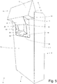
- the inner container 3 is cup-shaped and has an open upper end 5.
- the container 3 has a parallelepiped shape with a rectangular cross section.
- the inner container 3 comprises a lid 6, which is cup-shaped and is hinged to the inner container 3 along a hinge 7 to rotate, with respect to the inner container 3, between an open position (shown in Figures 2 and 3 ) and a closed position (shown in Figure 1 ) of the open upper end 5.
- the inner container 3 has a bottom wall 8 opposite to the open upper end 5, a front wall 9 and a rear wall 10 parallel and opposite one to the other, and two lateral walls 11 parallel to each other and interposed between the walls 9 and 10. Between the walls 9 and 10 and the lateral walls 11 are defined four longitudinal edges while between the walls 9, 10 and 11 and the bottom wall 8 are defined four transverse edges.
- the lid 6 is cup-shaped and has a top wall 12 (which, when the lid 6 is in the closed position, is opposite and parallel to the bottom wall 8 of the inner container 3), a rear wall 13 which is connected with the rear wall 10 of the inner container 3 by way of the hinge 7, and two lateral walls 14 parallel one, to the other. It is important to note that the lateral walls 14 of the lid 6 are arranged inside the lateral walls 11 of the inner container 3 as is clearly illustrated in Figures 4 and 5 .
- the outer container 4 is cup-shaped, is of parallelepiped shape with rectangular cross section, and has a bottom wall 15 opposite to an open top end 16, a front wall 17 and a rear wall 18 opposite and parallel with respect to each other, and two lateral walls 19 parallel one to the other and interposed between the walls 17 and 18. Between the walls 17 and 18 and the lateral walls 19 four longitudinal edges are defined while between the walls 17, 18 and 19 and the bottom wall 15 four transverse edges are defined.
- edges are straight; according to alternative embodiments not illustrated, some edges (longitudinal and/or transverse) may be beveled or rounded.
- the rear wall 13 of the lid 6 (in particular a top edge of the rear wall 13 of the lid 6 which delimits the rear wall 13 from the top wall 12) is connectable to the rear wall 18 of the outer container 4 by way of a connecting tab 20 to "automatically" control (i.e. without the user having to touch the lid 6) the rotation of the lid 6 by way of the sliding of the inner container 3 with respect to the outer container 4.
- the outer container 4 has a through window 21 that is formed astride the front wall 17 and of a lateral wall 19 and through which the front wall 9 of the container 3 is accessible to allow the application of a thrust to the inner container 3 in order to move the inner container 3 between the closed configuration and the open configuration.
- the outer container 4 comprises a sealing tab 22 that has the function of preventing the undesirable loss of tobacco dust through the gap that remains between the front edge of the top wall 12 of the lid 6 of the inner container 3 and the corresponding upper edge of the front wall 17 of the outer container 4.
- the sealing tab 22 is hinged to the upper edge of the front wall 17 of the outer container 4 and is movable between a working position (which is illustrated in Figure 1 and is assumed in the closed configuration, or when the inner container 3 is fully inserted in the outer container 4) and a rest position (which is illustrated in Figure 2 and is assumed in the open configuration, i.e. when the inner container 3 is partially extracted from the outer container 4).
- the sealing tab 22 is perpendicular to the front wall 17 of the outer container 4 and is arranged below the top wall 12 of the lid 6 of the inner container 3 so as to block the escape of tobacco dust by "sealing" the gap that remains between the front edge of the top wall 12 of the lid 6 of the inner container 3 and the facing upper edge of the front wall 17 of the outer container 4.
- the sealing tab 22 is parallel to the front wall 17 of the outer container 4 not thereby disrupting the relative movement between the inner container 3 the and outer container 4.
- the inner container 3 comprises an actuating tab 23 which is integral with the front wall 9 of the inner container 3 and protrudes towards the front wall 17 of the outer container 4.
- the outer container 4 comprises an actuating tab 24 which is mechanically connected to the sealing tab 22 and is arranged between the front wall 17 of the outer container 4 and the front wall 9 of the inner container 3 to engage (or hook) with the actuating tab 23 when the inner container 3 moves towards the rest position so as to pull the sealing tab 22 in the rest position by exploiting the movement of the inner container 3.
- the actuating tab 24 has a center through window 25 through which the actuating tab 23 is arranged; i.e. the actuating tab 23 enters the through window 25 of the actuating tab 24 to hook the actuating tab 24 and drag (push) the actuating tab 24 itself.
- the actuating tab 24 is connected to the sealing tab 22 by way of a connecting tab 26 which on one side is hinged to the actuating tab 24 (i.e. is connected to the actuating tab 24 along a fold line that allows a relative rotation) and the opposite side is hinged to the sealing tab 22 (that is connected to the sealing tab 22 along a fold line which allows relative rotation).
- the actuating tab 23 is formed by a part of the front wall 9 of the inner container 3 which is separated from the remaining part of the front wall 9 of the inner container 3 by an "U"-shaped through incision 27 and a fold line 28, which joins together the two ends of the "U"-shaped through incision 27.
- the inner container 3 also comprises a lifting tab 29 that is separated from the actuating tab 23 by the fold line 28 (i.e. the lifting tab 29 and the actuating tab 23 are initially arranged side by side and are separated by the fold line 28). The lifting tab 29 is folded about the fold line 28, by 180° to rest on an inner surface of the front wall 9 of the inner container 3.
- the function of the lifting tab 29 is to determine, due to the force of the spring back effect generated inside the wrapping material, a lifting of the actuating tab 23 with respect to the front wall 9 of the inner container 3: when the rotating tab 29 is rotated about the fold line 28, by 180°, the actuating tab 23 tends (due to the force of the spring back effect generated inside the wrapping material) to accomplish a similar rotation about the fold line 28 and therefore tends to rise with respect to the front wall 9 of the inner container 3 (as shown in Figure 4 ).
- the inner container 3 has a window 30 within which the connecting tab 20 is obtained and the edge of which has, at least in some areas, a certain distance from the edge of the connecting tab 20.
- the connecting tab 20 comprises a top portion 31, a top edge of which is integral with the lid 6 and that tilts with respect to the rear wall 10 of the inner container 3 to follow the rotation of the lid 6, an intermediate portion 32 that is connected to the top portion 31 along a pre-fold fold line, has a center hole and always remains parallel to the rear wall 10 of the inner container 3, and a bottom portion 33 that is connected to the intermediate portion 32 along a pre-fold fold line and is folded by 180° with respect to the intermediate portion 32 onto the intermediate portion 32 (giving the connecting tab 20 a "U” shape) to form a "hook".
- the lower portion 33 has a protrusion 34 from the side of the center hole of the intermediate portion 32, and when the lower portion 33 is folded by 180° with respect to the intermediate portion 32, the protrusion 34 comes out of the window 30 and slips partially below the rear wall 10 of the inner container 3.
- the outer container 4 comprises a further connecting tab 37 which is integral with the rear wall 18 of the outer container 4, rises from a top edge of the rear wall 18, and is folded by (about) 180° with respect to the rear wall 18 onto the rear wall 18 itself to have, together with the rear wall 18, a "U" shape.
- the mechanical connection between the rear wall 13 of the lid 6 and the rear wall 18 of the outer container 4 is made by a coupling between the two connecting tabs 20 and 37: the connecting tab 20 is arranged inside of the "U" defined by the connecting tab 37 and vice versa (i.e. the connecting tab 37 is arranged inside the "U" defined by the connecting tab 20); i.e.
- the connecting tab 37 has an appendix 37' which has the function of improving the mechanical connection between the two connecting tabs 20 and 37; in fact, the appendix 37' is inserted into the hole in the center of the intermediate portion 32 of the connecting tab 20 facilitating the mechanical connection between the two connecting tabs 20 and 37.
- the connecting tab 20 By the sliding effect of the connecting tab 20 within the window 30, the lower edge 35 of the connecting tab 20 gradually approaches towards the lower edge 36 of the window 30 until reaching a limit position of maximum opening or wherein the bottom edge 35 of the connecting tab 20 rests on the bottom edge 36 of the window 30. Once reaching said limit or maximum opening position, the connecting tab 20 can no longer slide downwards with respect to the window 30 as the lower edge 35 of the connecting tab 20 is in contact with the lower edge 36 of the window 30; consequently, it is not possible to further extract the inner container 3 from the outer container 4 and therefore it is not possible to further open by rotation the lid 6 about the hinge 7.
- the lower edge 35 of the connecting tab 20, together with the lower edge 36 of the window 30, is an "end-of-stroke" that establishes a maximum opening position (i.e. of maximum extraction of the inner container 3 from the outer container 4 and therefore of maximum rotation of the lid 6 about the hinge 7) further blocking the sliding of the inner container 3 (and therefore the further rotation of the lid 6 about the hinge 7) once reaching the maximum opening position thereof.
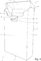
- the containers 3 and 4 of the package 1 of cigarettes shown in Figures 1 to 6 are obtained from corresponding blanks 38 and, respectively, 39 illustrated in Figures 7 and 8 .
- Each of the blanks 38 and 39 comprises, among other things, a number of elements, which will be marked, where possible, with accented reference numbers equal to the reference numbers as for the corresponding walls of the respective container 3 and 4.
- the inner blank 38 has two longitudinal fold lines and a number of transverse fold lines 41, which define, between the two longitudinal fold lines 40, at least one panel 9' which forms the front wall 9 of the inner container 3, a panel 8' which forms the bottom wall 8 of the inner container 3, a panel 10' which forms the rear wall 10 of the inner container 3, a panel 13' which forms the rear wall 13 of the lid 6, a panel 12' which forms the top wall 12 of the lid 6, a reinforcing panel 12" for the panel 12', a reinforcing panel 13" for the panel 13', and a reinforcing panel 10" for the panel 10'.
- the panel 12" is glued to the inside of the panel 12'
- the panel 13" rests on panel 13'
- the panel 10" is glued to the inside of the panel 10'.
- the panel 10' has two wings 11", which form an inner portion of the lateral walls 11 of the inner container 3, are arranged on opposite sides of panel 10', and are connected to the panel 10' by the longitudinal fold lines 40.
- the panel 13' has two wings 14' which form the lateral walls 14 of the lid 6, are arranged on opposite sides of panel 13', and are connected to the panel 13' by the longitudinal fold lines 40.
- the panel 10" has two reinforcing wings 11"' which are glued to the inside of the corresponding wings 11", are arranged on opposite sides of panel 10", and are connected to panel 10" by the longitudinal fold lines 40.
- Each wing 11" has a tab 42 which is connected to the wing 11' by a transverse fold line 41, is folded by 90° with respect to the wing 11", and is glued to an inner surface of the panel 8'.
- Each wing 14' has a tab 43 that is connected to the wing 14' by a transverse fold line 41, is folded by 90° with respect to wing 14', and is glued to an inner surface of the panel 12'.
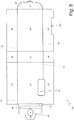
- the outer blank 39 has two longitudinal fold lines 44 and a number of transverse fold lines 45, which define, between the two longitudinal fold lines 44, a panel 17' forming the front wall 17 of the outer container 4, a panel 15' forming the bottom wall 15 of the outer container 4 and a panel 18' forming the rear wall 18 of the outer container 4.
- the panel 17' has two wings 19', which form an outer portion of the lateral walls 19 of the outer container 4, are arranged on opposite sides of the panel 17', and are connected to the panel 17' by longitudinal fold lines 44.
- the panel 18' has two wings 19", which form an inner portion of the lateral walls 19 of the outer container 4, are arranged on opposite sides of the panel 18', and are connected to the panel 18' by longitudinal fold lines 44.
- Each wing 19" has a tab 46 which is connected to the wing 19' by a transverse fold line 45, is folded by 90° with respect to the wing 19", and is glued to an inner surface of the panel 15'.
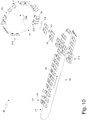
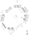
- FIG 9 a cigarette packing machine 47 is illustrated that produces the packages 1 of cigarettes of the type described above and illustrated in Figures 1 to 3 .
- the packing machine 47 comprises a packing unit 48 that produces the wrapped groups 2 of cigarettes, a subsequent packing unit 49 that produces the inner containers 3 by folding the blanks 38 about corresponding wrapped groups 2 of cigarettes received by the packing unit 48, a packing unit 50 that produces the outer containers 4 by folding the blanks 39 about corresponding inner containers 3 received by the packing unit 49, and a transfer unit 51 which receives in input the inner containers 3 from the packing unit 49 in correspondence to an input station 52 and feeds in output the inner containers 3 to the packing unit 50 in correspondence to an output station 53.
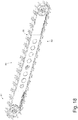
- the packing unit 49 comprises a packing conveyor 54 which is provided with a number of packing pockets 55 (shown in Figure 18 ), each of which is adapted to house an inner blank 38 to feed the inner blank 38 by steps (i.e. with intermittent motion composed by a succession of motion steps intercalated with a corresponding succession of stopping steps) along a packing path P1 that extends between an input station S1 and an output station S15 through a succession of work stations from S2 to S14 (illustrated in figures 11 and 12 ).
- steps i.e. with intermittent motion composed by a succession of motion steps intercalated with a corresponding succession of stopping steps
- a hopper (not shown) which houses a stack of inner blanks 38 and cyclically feeds the inner blanks 38 from a bottom outlet towards the packing pockets 55 of the packing conveyor 54; in particular, each inner blank 38 arranged in correspondence to the bottom outlet of the hopper is picked up by a suction gripping head that moves vertically and is supported to an underlying packing pocket 55 of the packing conveyor 54 that stops and waits in the input station S1 in alignment with the bottom outlet.
- each inner blank 38 feeds each inner blank 38 along the packing path P1 always transversely, i.e. always with the transverse fold lines 41 parallel to the feed direction; in other words, the packing conveyor 54 does not ever vary the orientation of each inner blank 38 with respect to the feed direction, and then in all the points of the packing path P1 each inner blank 38 has always its transverse fold lines 41 parallel to the feed direction (and thus its own longitudinal fold lines 40 perpendicular to the feed direction).
- Always maintaining a constant orientation of each inner blank 38 along the packing path P1 allows to simplify both the folding operations, and the structure of the packing conveyor 54.
- the packing conveyor 54 is constituted by a conveyor belt that is wrapped about two end pulleys and supports a number of packing pockets 55; accordingly, the packing path P1 has an "U" shape and extends between the input station S1 arranged along a straight initial portion of the packing path P1 and the output station S15 arranged along a straight end portion of the packing path P1 which is connected to the straight initial portion by way of an intermediate semicircular portion.
- a folding device 56 is provided having movable parts (i.e. parts that move to perform the folding operation while the inner blank 38 is stopped waiting in the work station S2); the folding device 56 simultaneously folds by 90° the panel 12', with respect to the panel 13' and the tabs 43 with respect to the wings 14' about the same transverse fold line 41 giving the inner blank 38 an "L" shape.
- a folding device 57 is provided having fixed folding profiles (i.e.
- the folding device 57 simultaneously folds by 90° the panel 12', with respect to the panel 13' and the tabs 43 with respect to the wings 14' about the same transverse fold line 41 and in the opposite direction to the similar fold made by the folding device 56 in the work station S2 giving again the inner blank 38 a flat shape.
- the two folding devices 56 and 57 perform two opposite folding operations (i.e. that cancel each other) having a flex function (i.e. weakening in order to considerably reduce the residual spring back force) the inner blank 38 along the corresponding transverse fold line 41. Therefore, the function of the two folding devices 56 and 57 is not to perform an actual folding of the inner blank 38, but rather to prepare the inner blank 38 for the subsequent folding operations (described below).
- a folding device 58 having movable parts (i.e. parts that move to perform the folding operation while the inner blank 38 is stopped waiting in the work station S3); the folding device 58 folds by 90°, the actuating tab 23 with respect to panel 9' and about the fold line 28, with the function of flexing the actuating tab 23 along the fold line 28.
- a gumming device 59 (typically provided with nozzles that spray gumming glue) which deposits glue points 60 (illustrated in Figure 12 ) on the panel 9' is provided.
- a folding device 61 is provided having fixed folding profiles (i.e. folding helixes that are devoid of moving parts and perform the folding operation while the inner blank 38 moves in the packing path P1 and thus exploiting the feeding movement of the inner blank 38); the folding device 61 folds by 180° the lifting tab 29 with respect to the panel 9' and about the fold line 28. In particular, the folding device 61 folds by 90° the lifting tab 29 with respect to the panel 9' and about the fold line 28 between the work station S3 and work station S4 (i.e.
- the lifting tab 29 in the work station S4 the lifting tab 29 is fold by 90° with respect to the panel 9'), and thereafter, the folding device 61 folds by further 90° (for a total of 180°) the lifting tab 29 with respect to the panel 9' and about the fold line 28 between the work station S4 and the work station S5 (i.e. in the work station S5 the lifting tab 29 is folded by 180° with respect to the panel 9' and onto the panel 9' itself to which is glued by the effect of the presence of glue 60).
- a folding device 62 is provided having movable parts (i.e. parts that move to perform the folding operation while the inner blank 38 is stopped waiting in the work station S4), the folding device 62 simultaneously folds by 90°, the reinforcing wings 11"' with respect to the panel 10" and about corresponding longitudinal fold lines 40 and folds by 180° the bottom portion 33 of the tab 20 with respect to the intermediate connecting portion 32, about a transverse fold line 41, and onto the intermediate portion 32 itself.
- a presser device 63 is provided having movable parts (i.e. parts that move to perform the pressing operation while the inner blank 38 is stopped waiting in the work station S5) that locally flattens the inner blank 38 by pressing on the lifting tab 29 to press the folding of the tab 29 again onto the lifting panel 9'.
- a rotating presser device 64 is arranged (i.e., consisting of a rotatable drum that by rotating "rolls" an outer surface on the inner blank 38 while the inner blank 38 moves in the packing path P1) that locally flattens the inner blank 38 by pressing on the bottom portion 33 of the connecting tab 20 to press the folding of the bottom portion 33 again onto the intermediate portion 32.
- a folding device 65 is provided having movable parts (i.e. parts that move to perform the folding operation while the inner blank 38 is stopped waiting in the work station S6), the folding device 65 folds by 90° the actuating tab 23 with respect to panel 9', about the fold line 28 and onto the panel 9' itself.
- a presser device 66 is provided having movable parts (i.e. parts that move to perform the pressing operation while the inner blank 38 is stopped waiting in the work station S6) that locally flattens the inner blank 38 by pressing on lifting tab 29 to press both the folding of the lifting tab 29 again onto an inner wall of the panel 9', and the folding of the actuating tab 23 onto an outer wall of the panel 9'.
- a rotating presser device 67 is arranged (i.e., consisting of a rotatable drum that by rotating "rolls" an outer surface on the inner blank 38 while the inner blank 38 moves in the packing path P1) that locally flattens the inner blank 38 by pressing on the lifting tab 29 and on the actuating tab 23 to press the folding of the lifting tab 29 and of the actuating tab 23 again onto the panel 9'.
- a gumming device 68 is provided (typically provided with nozzles that spray gumming glue) which deposits glue points 69 (illustrated in Figure 12 ) on the panel 12', on the tabs 43 and on the wings 11".
- Folding means fold the inner blank 38 so as to form a hinged lid 6.
- the aforementioned folding means overlap at least one reinforcing panel at least on the first panel 10' during the forming of the lid 6.
- the first folding means overlap at least the reinforcing panel 10" at least on the first panel 10' during the forming of the lid 6.
- said folding means form the lid 6 leaving flat the other parts of the blank 38 different therefrom.
- Said folding means preferably comprise a number of folding devices 70, 71, 72, 73, as hereinafter described in greater detail.
- a folding device 70 is arranged which is provided with fixed folding profiles (i.e. folding helixes that are devoid of moving parts and perform the folding operation while the inner blank 38 moves in the packing path P1 and thus exploiting the feeding movement of the inner blank 38); the folding device 70 folds by 90°, the panel 12" with respect to panel 12' and about a corresponding transverse fold line 41.
- a folding device 71 is provided having movable parts (i.e. parts that move to perform the pressing operation while the inner blank 38 is stopped waiting in the work station S10).
- the folding device 71 initially folds the tabs 43 by 90° with respect to the wings 14' and about corresponding transverse fold lines 41, and subsequently at the same time (i.e.
- a folding device 72 is arranged which, is provided with fixed folding profiles (i.e. folding helixes that are devoid of movable parts and perform the folding operation while the inner blank 38 moves in the packing path P1 and thus exploiting the feeding movement of the inner blank 38), the folding device 72 folds the panel 13" by 90°, with respect to panel 12" about a corresponding transverse fold line 41 and in the opposite direction to the similar fold made by the folding device 71 in the work station 10.
- the two folding devices 71 and 72 perform two opposite folding operations (i.e. that cancel each other) between the two panels 12" and 13" having the function of flexing (or weakening to considerably reduce the residual spring back force) the inner blank 38 along the corresponding transverse fold line 41.
- a folding device 73 having movable parts (i.e. parts that move to perform the folding operation while the inner blank 38 is stopped waiting in the work station S11), the folding device 73 simultaneously (i.e. together) fold the panel 12" by 90°, with respect to panel 12' and about a corresponding transverse fold line 41 (in this way the panel 12" rests to the panel 12' to which is glued due to the presence of the glue 69) and folds the panel 13" by 90° with respect to panel 12" and about a corresponding transverse fold line 41 (in this way the panel 13" rests to the panel 13', the panel 10" rests on the panel 10' to which is glued due to the presence of the glue 69 and the wings 11"' overlap with the wings 11" without resting; in a subsequent work station the wings 11"' will be glued to the wings 11" due to the presence of the glue 69).
- a presser device 74 is provided having movable parts (i.e. parts that move to perform the folding operation while the inner blank 38 is stopped waiting in the work station S12) that locally flattens the inner blank 38 by pressing on the panel 10" to press the folding of the panel 10" again onto the panel 10'.
- a presser device 75 is provided, identical to the previous presser device 74, which is provided with movable parts (i.e. parts that move to perform the folding operation while the inner blank 38 is stopped waiting in the work station S13) that locally flattens the inner blank 38 by pressing on the panel 10" to press the folding of the panel 10" again onto the panel 10'.
- movable parts i.e. parts that move to perform the folding operation while the inner blank 38 is stopped waiting in the work station S13
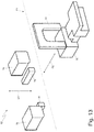
- the folding device 62 comprises two lateral folding bodies 76 of parallelepiped shape and a center folding body 77 "U"-shaped which are mounted on the same carriage to move cyclically along a direction D1 of vertical work that is perpendicular to the packing path P1. Furthermore, the folding device 62 comprises two lateral contrast bodies 78 of parallelepiped shape and a center contrast body 79 that are mounted on the same carriage to move cyclically along a horizontal work direction D2 that is perpendicular to both the packing path P1, and the vertical work direction D1.
- the two lateral folding bodies 76 move from top to bottom along the vertical work direction D1 to fold the reinforcing wings 11"' by 90° with respect to panel 10" and about corresponding longitudinal fold lines 40; in this step the two contrast bodies 78 are arranged below the panel 10" and from opposite sides of the panel 10" close to the longitudinal fold lines 40 to provide a contrast for the two lateral folding bodies 76.
- the folding body 77 moves downwards along the vertical work direction D1 to fold the bottom portion 33 of the connecting tab 20 by 90°, with respect to the intermediate portion 32 and about a transverse fold line 41; in this step, the center contrast body 79 is arranged below the panel 10' in correspondence to the connecting tab 20 to provide a contrast for the folding body 77.
- the contrast bodies 78 and 79 move together along the horizontal work direction D2: the two contrast bodies 78 move along the horizontal work direction D2 to move from the trajectory of the reinforcing wings 11"' and thus allow the subsequent feeding of the inner blank 38 along the packing path P1, while the center contrast body 79 moves in the horizontal work direction D2 to fold by further 90° (i.e., for a total of 180°) the bottom portion 33 of the connecting tab 20 with respect to the intermediate portion 32 and about a transverse fold line 41 so as to fold the portion 33 onto the intermediate bottom portion 32 itself.
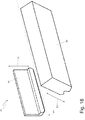
- the folding device 65 comprises a folding body 80 which performs a folding roto-translation movement perpendicular to the packing path P1 and is supported by an articulated quadrilateral 81.
- the folding device 71 comprises a folding body 82 that has in section a "L" shape and is movable in the horizontal work direction D2 (which is perpendicular to the packing path P1). Furthermore, the folding device 71 comprises a folding body 83 which has a center folding member 84, two top lateral members 85 arranged on opposite sides of the center member 84, and two bottom lateral members 86 also arranged on opposite sides of the center member 84.
- the folding device 71 is movable in the vertical work direction D1 (which is perpendicular to both the packing path P1, and the horizontal work direction D2); in addition, the center member 84, the two top lateral members 85, and the two bottom lateral members 86 are arranged in different positions vertically (i.e. along the work direction D1) to execute in succession respective folding of the inner blank 38 while the folding body 83 moves vertically with a continuous movement (i.e. along the work direction D1). Finally, the folding device 71 comprises a contrast body 87 which has a "hoe"-shaped center member 88 and two lateral appendixes 89 arranged on opposite sides of the center member 88 and is mounted to rotate about an axis of rotation 90 parallel to the packing path P1.
- the contrast body 87 rotates about the axis of rotation 90 to arrange the two lateral appendixes 89 above the wings 14' and close to the tabs 43, to form a contrast for the top lateral members 85 of the folding body 83, and then the folding body 83 moves from the bottom upwards in the vertical work direction D1 so that the two top lateral members 85 fold the tabs 43 by 90°, with respect to the wings 14' and about corresponding transverse fold lines 41.
- the contrast body 87 rotates in reverse about the axis of rotation 90 to remove the two appendixes 89 from the wings 14' and at the same time to rest the center member 88 on the panel 13' , to form a contrast to the center member 84 of the folding body 83, and then the folding body 83 moves further upwards along the vertical work direction D1 so that two bottom lateral members 86 fold the wings 14' by 90° with respect to the panel 13' and about corresponding longitudinal fold lines 40 and at the same time the center member 84 fold the panel 12' by 90°, with respect to the panel 13' and about a corresponding transverse fold line 41 (in this way the tabs 43 rest on the panel 12' to which are glued by the effect of the presence of glue 69).
- the folding body 82 moves in the horizontal work direction D2 and towards the contrast body 87 to fold the panel 12" by 90°, and onto the contrast body 87 with respect to the panel 12' and to fold the panel 13" by 90°, with respect to the panel 12" and about a corresponding transverse fold line 41.
- the folding device 73 comprises a folding body 91 which is movable in the vertical work direction D1 (which is perpendicular to the packing path P1), and an aligner body 92 which is movable in a tilted work direction D3 (which is not parallel to the vertical work direction D1, nor to the horizontal work direction D2, nor to the packing path P1).
- the folding body 91 moves downwards along the vertical work direction D1 to fold the panel 12" by 90°, with respect to the panel 12' and about a corresponding transverse fold line 41 (in this way the panel 12" rests on the panel 12' to which is glued due to the presence of glue 69) and to simultaneously fold the panel 13" by 90°, with respect to the panel 12" and about a corresponding transverse fold line 41 (in this way the panel 13" rests on the panel 13', the panel 10" rests on the panel 10' to which is glued due to the presence of glue 69, and the wings 11"' overlap the wings 11" without resting; in a subsequent work station the wings 11"' will be glued to the wings 11" due to the presence of glue 69).
- the aligner body 92 moves downwards in the tilted work direction D3 to hold down the end edge of the panel 10".
- the aligner body 92 can remain lowered and hold down the end edge of the panel 10", maintaining the panels 10" and 13" in the correct position facing the underlying corresponding panels 10' and 13', and keeping the panel 12" pressed onto the underlying panel 12'.
- the fact that the folding device 62 folds the reinforcing wings 11"' by 90°, and subsequently downstream from the folding device 62 the reinforcing wings 11"' are set free facilitates the fact that the reinforcing wings 11"' remain slightly raised with respect to the underlying wings 11".
- the wings 11"' are pressed onto the wings 11" to complete the gluing between the wings 11"' and the wings 11" due to the presence of glue 69, simultaneously with the folding of the wings 11" by 90°, with respect to panel 10' and about corresponding longitudinal fold lines 40.
- the wings 11"' are glued to the wings 11" when the wings 11" are in perpendicular position to the panel 10' and this cannot happen in a work station of the packing path P1, since along the packing path P1 the wings 11" always remain coplanar with the panel 10'.
- the packing unit 49 comprises a packing conveyor 93 which is provided with a number of packing pockets 94 (illustrated schematically in Figure 19 ), each of which is adapted to house an inner blank 38 and the corresponding wrapped group 2 of cigarettes for feeding the inner blank 38 and the wrapped group 2 of cigarettes along a packing path P2 that extends between an input station S16 and an output station S18.
- an inner blank 38 partially pre-folded and coming from the packing conveyor 54 is fed into a packing pocket 94 causing a further folding of the inner blank 38 itself.
- a wrapped group 2 of cigarettes is fed inside a packing pocket 94 to be coupled to the previously fed inner blank 38; in particular, a rear wall of the wrapped group 2 of cigarettes rests on the panel 10' of the inner blank 38.
- the inner container 3 (formed by folding the inner blank 38 about the wrapped group 2 of cigarettes) is extracted from the packing pocket 94 and proceeds towards the packing unit 50.
- a drying conveyor (shown schematically in Figure 9 ) is arranged that transfers the inner containers 3 to the packing unit 50.
- Additional folding means fold the inner blank 38 about the first panel 10' to give the same a cup shape about the first panel 10' itself.
- Said folding means are preferably constituted by a folding device 95, as hereinafter described in greater detail.
- the above-mentioned feed station S17 is therefore arranged downstream from the folding device 95.
- the folding device 95 is arranged between the devices 70, 71, 72, 73 and the folding feed station S17.
- a folding device 95 is arranged, which folds the tabs 42 of the inner blank 38 by 90°, with respect to the wings 11", and then, by inserting the inner blank 38 into the packing pocket 94, determines the folding of the panel 8' by 90°, with respect to the panel 10' and the folding of the two wings 11" by 90°, with respect to the panel 10'; in other words, after the folding of the tabs 42 by 90°, the input of the inner blank 38 in the packing pocket 94 determines the folding of the panel 8' by 90°, and of the two wings 11" by 90°, with respect to the panel 10' and in this way the tabs 42 rest on the panel 8'.
- a folding device 96 is arranged, which folds the panel 9' by 90°, with respect to panel 8' and about a corresponding transverse fold line 41.
- the folding of the inner blank 38 is completed in the output station S18 simultaneously with the extraction of the inner container 3 from the packing pocket 94: during the extraction of the inner container 3 from the packing pocket 94 a folding device 97 folds the wings 11' by 90°, with respect to the panel 9', onto the wings 11" and about corresponding longitudinal fold lines 40 completing the formation of the lateral walls 11 of the inner container 3; preferably, a gumming device (not shown) is arranged immediately upstream from the folding device 97 for depositing glue between the wings 11' and 11" immediately before folding the wings 11'.
- an opening device 98 upstream from the feed station S17 an opening device 98 is arranged that by rotating the formed lid 6 in each inner blank 38 about corresponding hinge 7 moves the formed lid 6 from the closing position to the opening position so that in the feed station S17 the respective wrapped group 2 of cigarettes can be inserted more easily into the inner blank 38, in particular, in the feed station S17 the wrapped group 2 of cigarettes can be inserted with a substantially axial (or longitudinal) movement into the inner blank 38. Consequently, downstream from the feed station S17 a closing device 99 is arranged that by rotating the formed lid 6 of each inner blank 38 about corresponding hinge 7 moves the formed lid 6 from the open position to the closed position before continuing folding of the inner blank 38.
- the lid 6 of the container 3 is formed.
- at least one reinforcing panel defined by a panel in correspondence with the end of the blank 38 and adjacent to the panels designed to form the lid 6 itself, is superimposed on (and possibly glued) to the panel 10' forming the rear wall 10 of the inner container 3. Further steps of folding the blank 38 confer a cup conformation to the same.
- the opening and closing of the formed lid 6 allow the insertion of wrapped group 2 of cigarettes over at least the reinforcing panel 10" of the rear wall 10 of the inner container 3, partially already formed, otherwise not achievable.
- the opening device 98 is preferably arranged between the folding device 95 and the feed station S17.
- the packing conveyor 93 is constituted by a rotating wheel which rotates by steps about a central axis of rotation 100 arranged horizontally. Consequently, the packing path P2 that extends from the input station S16 to the output station S18 has a circular shape.
- the packing unit 49 comprises a transfer conveyor 101 which transfers the pre-folded inner blanks 38 from the output station S15 of the packing conveyor 54 to the input station S16 of the packing conveyor 93.
- a gumming device 102 that deposits glue between the tabs 42 and the panel 8' of the inner blank 38 is arranged.
- one inner blank 38 at a time is fed to the packing conveyor 54 in the input station S1 of the packing path P1, and the transfer conveyor 101 transfers two inner blanks 38 at a time from the packing conveyor 54 to the packing conveyor 93; in this embodiment, the packing conveyor 93 at each step treats two inner blanks 38 at a time.
- two inner blanks 38 at a time are fed to the packing conveyor 54 in the input station S1 of the packing path P1.
- the packing unit 50 comprises a packing conveyor 103 that is provided with a number of packing pockets 104 (illustrated in Figure 23 ), each of which is adapted to house an outer blank 39 to feed the outer blank 39 by steps (i.e. with intermittent motion composed by a succession of motion phases intercalated with a corresponding succession of stop phases) along a packing path P3 that extends between an input station S19 and an output station S33 through a succession of work stations from S20 to S32 (illustrated in figures 21 and 22 ).
- a hopper (not shown) is provided, which houses a stack of outer blanks 39 and cyclically feeds the outer blanks 39 from a bottom outlet towards the packing pockets 104 of the packing conveyor 103; in particular, each outer blank 39 arranged at the bottom outlet of the hopper is picked up by a suction gripping head that moves vertically and rests on an underlying packing pocket 104 of the packing conveyor 103 that is stopped waiting in the input station S19 in alignment with the bottom output.
- the packing conveyor 103 advances each outer blank 39 along the packing path P3 always transversely, or always with the transverse fold lines 45 parallel to the feed direction, in other words, the packing conveyor 103 does not ever vary the orientation of each outer blank 39 with respect to the feed direction and therefore in all the points of the packing path P3 each outer blank 39 always has its transverse fold lines 45 parallel to the feed direction (and thus their own longitudinal fold lines 44 perpendicular to the feed direction).
- always maintaining a constant orientation of each outer blank 39 along the packing path P3 allows to simplify both the folding operations, and the structure of the packing conveyor 103.
- the packing conveyor 103 is constituted by a conveyor belt that is wrapped about two end pulleys and supports a number of packing pockets 104; accordingly, the packing path P3 has an "U" shape and extends between the input station S19 arranged along an initial portion of the rectilinear packing path P3 and the output station S33 arranged along a final portion of the rectilinear packing path P3 that is connected to the initial straight portion by way of an intermediate semicircular portion.
- a folding device 105 is provided having movable parts (i.e. parts that move to perform the folding operation while the outer blank 39 is stopped waiting in the work station S21); the folding device 105 simultaneously folds by 90° the appendix 37' with respect to connecting tab 37 and about a corresponding transverse fold line 45, the connecting tab 37 with respect to the panel 18' and about a corresponding transverse fold line 45, and the sealing tab 22 with respect to the panel 17' and about a corresponding transverse fold line 45.
- movable parts i.e. parts that move to perform the folding operation while the outer blank 39 is stopped waiting in the work station S21
- the folding device 105 simultaneously folds by 90° the appendix 37' with respect to connecting tab 37 and about a corresponding transverse fold line 45, the connecting tab 37 with respect to the panel 18' and about a corresponding transverse fold line 45, and the sealing tab 22 with respect to the panel 17' and about a corresponding transverse fold line 45.
- a folding device 106 is provided having fixed folding profiles (i.e. folding helixes that are devoid of moving parts and perform the folding operation while the outer blank 39 moves in the packing path P3 and thus exploiting the feeding movement of the outer blank 39), the folding device 106 of folds the connecting tab 37 by further 90° (for a total of 180°) and simultaneously with respect to the panel 18' and about a corresponding transverse fold line 45 to rest the connecting tab 37 on the panel 18' (while the appendix 37' is folded on the opposite side of the tab 37 with respect to the panel 18'), and the sealing tab 22 with respect to the panel 17' and about a corresponding transverse fold line 45 to rest the sealing flap 22 on the panel 17'.
- fixed folding profiles i.e. folding helixes that are devoid of moving parts and perform the folding operation while the outer blank 39 moves in the packing path P3 and thus exploiting the feeding movement of the outer blank 39
- the folding device 106 of folds the connecting tab 37 by further 90° (for a total of
- a folding device 107 is provided having fixed folding profiles (i.e. folding helixes that are devoid of moving parts and perform the folding operation while the outer blank 39 moves in the packing path P3 and thus exploiting the feeding movement of the outer blank 39); the folding device 107 folds the sealing tab 22 by 180°, with respect to the panel 17' with opposite direction with respect to the previous folds performed by the folding devices 105 and 106.
- the folding device 107 and the two folding devices 105 and 106 (when acting on the sealing tab 22) perform two opposite folding operations (i.e. that cancel each other) having a flex function of (i.e. weakening to considerably reduce the residual spring back force) the outer blank 39 along the corresponding transverse fold line 45. Therefore, the function of the folding devices 105, 106 and 107 (when acting on the sealing tab 22) is not to perform an actual folding of the outer blank 39, but to prepare the outer blank 39 for the successive folding operations (described below).
- a folding device 108 is provided having movable parts (i.e. parts that move to perform the folding operation while the inner blank 39 is stopped waiting in the work station S26); the folding device 108 folds the connecting tab 26 by 90°, with respect to the sealing tab 22 and the about a corresponding transverse fold line 45.
- a device 109 for folding is provided having fixed folding profiles (i.e. folding helixes that are devoid of moving parts and perform the folding operation while the outer blank 39 moves in the packing path P3 and thus exploiting the feeding movement of the outer blank 39), the folding device 109 folds the connecting tab 26 by a further 90° (for a total of 180°) with respect to the sealing tab 22 and about a corresponding transverse fold line 45 to rest the connecting tab 26 on the sealing tab 22 (and thus to rest the actuating tab 24 on the panel 17').
- fixed folding profiles i.e. folding helixes that are devoid of moving parts and perform the folding operation while the outer blank 39 moves in the packing path P3 and thus exploiting the feeding movement of the outer blank 39
- the folding device 109 folds the connecting tab 26 by a further 90° (for a total of 180°) with respect to the sealing tab 22 and about a corresponding transverse fold line 45 to rest the connecting tab 26 on the sealing tab 22 (and thus to rest the actuating tab 24 on
- a rotating presser device 110 is arranged (i.e. consisting of a rotatable drum that by rotating "rolls" an outer surface on the inner blank 38 while the inner blank 38 moves in the packing path P3) that locally flattens the outer blank 39 by pressing on the connecting tab 26 to press the folding of the connecting tab 26 again onto the sealing tab 22.
- the packing unit 50 comprises a packing conveyor 111 that is provided with a number of packing pockets 112 (illustrated schematically in Figure 24 ), each of which is adapted to accommodate an outer blank 39 and the corresponding inner container 3 for feeding the outer blank 39 and the inner container 3 along a packing path P4 that extends between an input station S34 and an output station S36.
- an outer blank 39 partially pre-folded and coming from the packing conveyor 103 is fed into a packing pocket 112 causing a further folding of the outer blank 39 itself.
- an inner container 3 is fed into a packing pocket 112 to be coupled to the outer blank 39 previously feed; in particular, the rear wall 10 of the inner container 3 rests to the panel 18' of the outer blank 39.
- the outer container 4 (formed by folding the outer blank 39 about the inner container 3) almost completely full is extracted from the packing pocket 112 and proceeds along a further packing path P5 and a drying path P6 arranged in succession, and then through two more work stations S37 and S38 arranged downstream from the packing conveyor 111.
- the drying path P6 is defined by a drying conveyor (shown schematically in Figure 9 ) that transfers the outer containers 4 towards an outlet of the packing machine 47.
- a folding device 113 is arranged, which folds the tabs 46 of the outer blank 39 by 90°, with respect to the wings 19", and then, by inserting the outer blank 39 into the packing pocket 112, determines the folding of the panel 15' by 90° with respect to the panel 18' and the folding of the two wings 19" by 90° with respect to the panel 18'; in other words, after the folding of the tabs 46 by 90°, the input of the outer blank 39 in the packing pocket 112 determines the folding of the panel 15' and the two wings 19" by 90° with respect to the panel 18' and in this way the tabs 46 rest on the panel 15'.
- a folding device 114 is arranged, which folds the panel 17' by 90° with respect to panel 15' and about a corresponding transverse fold line 45.
- the folding of the outer blank 39 is completed in the work station S37 after the extraction of the outer container 4 from the packing pocket 112 (i.e.
- a folding device 115 folds by 90° the wings 19' with respect to the panel 17', onto the wings 19" and about corresponding longitudinal fold lines 44 completing the formation of the lateral walls 19 of the outer container 4; preferably, a gumming device (not shown) is arranged immediately upstream from the folding device 115 for depositing glue between the flanges 19' and 19" immediately before the folding of the wings 19'.
- the packing conveyor 111 is constituted by a rotating wheel which rotates by steps about a horizontally arranged central axis of rotation 116. Consequently, the packing path P4 that extends from the input station S34 to the output station S36 has a circular shape.
- the packing path P5 and the subsequent drying path P6 are rectilinear and arranged perpendicularly one to the other.
- the packing unit 50 comprises a transfer conveyor 117 which transfers the pre-folded outer blanks 39 from the output station S33 of the packing conveyor 103 to the input station S34 of the packing conveyor 111.
- a gumming device 118 is arranged which deposits glue between the tabs 46 and the panel 15' of the outer blank 39.
- an outer blank 39 at a time is fed to the packing conveyor 103 in the input station S19 of the packing path P3, and the transfer conveyor 117 transfers two outer blanks 39 at a time from the packing conveyor 103 to the packing conveyor 111, in this embodiment, the packing conveyor 111 treats at each step two outer blanks 39 at a time.
- two outer blanks at a time 39 are fed to the packing conveyor 103 in the input station S19 of the packing path P3.
- a folding device 119 of the type described in Italian patent application BO2011A000632 is arranged in the work station S38 .
- the sealing tab 22 is not bent so as to leave the sealing tab 22 in an initial position wherein the sealing tab 22 is coplanar with the front wall 17 of the outer container 4; in other words, when the outer container 4 enters in the work station S38 the sealing tab 22 is coplanar with the front wall 17 of the outer container 4.
- the folding device 119 partially extracts the inner container 3 from the outer container 4 by way of a sliding movement between the inner container 3 and the outer container 4, successively the folding device 119 folds the sealing tab 22 by 90°, about a corresponding and transverse fold line 45 towards the inner container 3 to arrange the sealing tab 22 in the work position under the top wall 12 of the lid 6 of the inner container 3, and finally the folding device 119 fully inserts the inner container 3 in the outer container 4 by way of a sliding movement between the inner container 3 and the outer container 4.
- the folding device 119 For a more detailed description of the operation of the folding device 119 refer to what is described in Italian patent application BO2011A000632 .
- the blanks 38 and 39 show alignment through windows 120 which are arranged at the lateral periphery of the blanks 38 and 39 (i.e. in correspondence to the wings 11" and 19") and have the function to ensure proper longitudinal alignment of the blanks 38 and 39 when the blanks 38 and 39 themselves are inserted into the corresponding packing pockets 55 and 104 of the packing conveyors 54 and 103.
- the packing pockets 55 and 104 of the packing conveyors 54 and 103 have reference bodies that reproduce in negative the shape of the alignment windows 120 and are inserted within the alignment windows 120 when the blanks 38 and 39 are inserted into the corresponding packing pockets 55 and 104; in this way a correct longitudinal alignment of the blanks 38 and 39 within the corresponding packing pockets 55 and 104 is ensured.
- FIG 25 a variant of the outer blank 39 is shown that, with respect to the outer blank 39 shown in Figure 8 , has a different shape and position of the alignment windows 120. It is important to note that the alignment windows 120 are formed in the wings 11" and 19" which constitute an inner portion of the lateral walls 11 and 19; then the alignment windows 120 are not visible (i.e. are covered by the wings 11' and 19') in the inner container 3 and in the outer container 4.
- the through window 21 of the wing 19' of the outer blank 39 adapted to allow the user to apply the necessary thrust to slide the inner container 3 with respect to the outer container 4 ( Figure 2 ) must not be limited by the alignment window 120 of the corresponding wing 19" of the outer blank 39.
- the alignment window 120 which faces the through window 21 should have a greater dimension than the through window 21 itself, as shown in Figures 8 and 25 .
- the packing method and the corresponding packing machine 47 described above have many advantages, as they allow to produce the slide-open packages 1 with a hinged lid with high productivity (i.e. with a high number of packages 1 of cigarettes produced per unit of time) while maintaining a high quality standard.
- This result is obtained thanks to the conformation of the packing units 49 that by completing the formation of the lid 6 in the packing conveyor 54 (i.e. before coupling the inner blank 38 to the wrapped group 2 of cigarettes) allows to form the lid 6 in a simple and effective way and simultaneously allows to greatly simplify the folding of the inner blank 38 about the wrapped group 2 of cigarettes.
- the formation of the lid 6 is easier (and therefore simple and fast) along a straight packing path (as, indeed, is the packing path P1 of the packing conveyor 54), while the folding of the inner blank 38 about the wrapped group 2 of cigarettes is easier (and therefore simple and fast) along a circular packing path (as, indeed, is the packing path P2 of the packing conveyor 93). So, thanks to the conformation of the packing units 49 all the folding operations can be performed in the most favorable situation, and therefore can be performed quickly (i.e. with a high productivity of the packing process) while ensuring a high quality standard.
- the packing method and the corresponding packing machine 47 described above are extremely "flexible", i.e. allow to vary quickly and simply the type of slide-open packages 1 of cigarettes that are produced (with the hinged lid 6 comprised in the inner blank 38 or comprised in the outer blank 39 or without hinged lid).
- each packing unit 49 or 50 there is a first packing conveyor 54 or 103 wherein a preliminary folding of the inner blank 38 or outer blank 39 is performed and a second packing conveyor 93 or 111 wherein the preliminary folding of the inner blank 38 or outer blank 39 is completed; in fact, thanks to the presence of the first packing conveyor 54 or 103 it is relatively simple to perform the preliminary folding of the inner blank 38 or outer blank 39 to form a lid, and once the lid is formed the final folding of the inner blank 38 or outer blank 39 is "conventional" (i.e. analogous to the folding of a standard blank) and therefore devoid of particular complications.
- both packing units 49 and 50 have the same structure that comprises a first packing conveyor (the packing conveyors 54 and 103) consisting in a conveyor belt and intended to produce a preliminary folding of the blank, a second packing conveyor (the packing conveyors 93 and 111) consisting in a wheel and intended to fold the blank (already partially folded) about the content, and a transfer conveyor (the transfer conveyors 101 and 117) that connects the two packing conveyors.
- the two second packing conveyors (the packing conveyors 93 and 111) of the two packing units 49 and 50 perform almost all the packing operations in the same way and in the same areas.
- the two packing units 49 and 50 can share between one another a large number of components, i.e. the same identical component is frequently present in both packing units 49 and 50 (in particular, the two packing units 49 and 50 can have in common at least 70-80% of the components); in this way, it is possible to break down in a very significant way the production, assembly and maintenance cost of the packing machine 47.
Landscapes
- Engineering & Computer Science (AREA)
- Mechanical Engineering (AREA)
- Packaging Of Annular Or Rod-Shaped Articles, Wearing Apparel, Cassettes, Or The Like (AREA)
- Wrapping Of Specific Fragile Articles (AREA)
- Cartons (AREA)
- Perforating, Stamping-Out Or Severing By Means Other Than Cutting (AREA)
- Auxiliary Devices For And Details Of Packaging Control (AREA)
- Supplying Of Containers To The Packaging Station (AREA)
Description
- The present invention relates to a packing machine and a packing method for producing an inner container of a slide-open package of tobacco articles.
- The rigid packages of cigarettes of the type with a hinged lid are currently the most widespread cigarette packages in the market as they are of simple construction, easy and practical to use and offer good mechanical protection to the cigarettes contained within.
- Besides the aforementioned rigid packages of cigarettes with a hinged lid, packages of cigarettes have been proposed with rigid slide-open (or sliding) covers comprising two containers inserted one inside the other in a separable way. In other words, a package of cigarettes with rigid slide-opening comprises an inner container, which is adapted to accommodate a wrapped group of cigarettes in a wrapping sheet of metalized paper and is housed within an outer container so as to be able to slide with respect to the outer container itself between a closed configuration, wherein the inner container is inserted inside the outer container, and an open configuration, wherein the inner container is extracted from the outer container.
- Also proposed was a rigid slide-open package of cigarettes and with a hinged lid, wherein the inner container (or, alternatively, the outer container) is provided with a hinged lid to rotate between a closed position and an open position of an open top end of the inner container. The lid has a connecting tab that at one end is integral with the lid and at the opposite end is integral with the outer container (or, alternatively, to the inner container) to control "automatically" (i.e. without the user having to touch the lid) the rotation of the lid by sliding the inner container with respect to the outer container.
- In particular, in a rigid package of cigarettes of the slide-opening type and with a hinged lid the connecting tab which "automatically" controls the rotation of the lid has a top end that is integral with a top or rear wall of the lid and a bottom end that, during the opening of the package of cigarettes, couples with a coupling tongue integral with a rear wall of the outer container.
- It was observed that the known current mode used for producing the packages of cigarettes of the slide-opening type and with a hinged lid does not allow to achieve high productivity (i.e. a high number of packages of cigarettes produced per unit of time), especially if it is necessary to maintain a high quality standard. Consequently, the known packing machines used for producing packages of cigarette of the slide-open type and with a hinged lid are excessively slow and suitable to produce only limited batches for special series.
- Additionally, but not less important, the known packing machines used for producing packages of cigarettes of the slide-opening type and with a hinged lid are not "flexible", i.e. it is very complicated to modify a packing machine which produces a certain type of slide-opening cigarette package (with or without a hinged lid) to produce another type of slide-opening cigarette package (with or without a hinged lid).
- The patent application
US2011041463A1 describes a packing machine for cigarettes for producing a rigid package with hinged lid. The packing machine is provided with a first packing unit, which is adapted to fold a first blank about a group of cigarettes to form an outer container provided with a hinged lid, and a second packing unit, which is adapted to fold a second blank about the outer container to form a tubular slider arranged about the outer container to slide axially with respect to the outer container itself; the tubular slider is provided with a transmission element, which has a first end integral with the lid, a second end opposite the first end and integral with the slider, and an intermediate portion which is deformable and has an "U" fold arranged between the outer container and the slider. - Purpose of the present invention is to provide a packing machine and a packing method for producing an inner container of a slide-open package of tobacco articles and with a hinged lid, which machine and packing method are free from the drawbacks described above and, in particular, are simple and economical to produce.
- According to the present invention, a packing machine and a packing method for producing an inner container of a slide-open package of tobacco articles, as claimed in the appended claims are provided.
- The present invention will now be described with reference to the accompanying drawings, which illustrate a non-limiting embodiment, wherein:
-
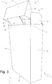
Figure 1 is a front perspective view and in a closed configuration of a package of cigarettes of the rigid type with slide-opening and with a hinged lid; -
Figure 2 is a front perspective view and in an open configuration of the package of cigarettes ofFigure 1 ; -
Figure 3 is a rear perspective view and in an open configuration of the package of cigarettes ofFigure 1 ; -
Figure 4 is a front perspective view of an inner container of the package of cigarettes ofFigure 1 ; -
Figure 5 is a rear perspective view of the inner container ofFigure 4 ; -
Figure 6 is a top perspective view of an outer container of the package of cigarettes ofFigure 1 ; -
Figure 7 is a plan view of an inner blank used for producing the inner container ofFigure 4 ; -
Figure 8 is a plan view of an outer blank used for producing the outer container ofFigure 6 ; -
Figure 9 is a schematic perspective view of a packing machine that produces the package of cigarettes ofFigure 1 and is made according to the present invention; -
Figure 10 is a schematic perspective view of a first packing unit of the packing machine offigure 9 ; -
Figure 11 is a schematic perspective view of a first packing conveyor of the first packing unit ofFigure 10 ; -
Figure 12 is a plan view of a sequence of preliminary folding of the inner blank offigure 7 operated in the first packing conveyor ofFigure 11 ; -
Figures 13 to 16 are four schematic and perspective views of four corresponding folding devices associated with the first packing conveyor; -
Figure 17 is an enlarged-scale view of a detail ofFigure 11 ; -
Figure 18 is a schematic and perspective view of a belt conveyor of the first packing unit ofFigure 10 ; -
Figure 19 is a schematic perspective view of a second packing conveyor of the first packing unit ofFigure 10 ; -
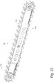
Figure 20 is a schematic perspective view of a second packing unit of the packing machine offigure 9 ; -
Figure 21 is a schematic perspective view of a first packing conveyor of the second packing unit ofFigure 20 ; -
Figure 22 is a plan view of a sequence of preliminary folding of the outer blank offigure 8 operated in the first packing conveyor ofFigure 21 ; -
Figure 23 is a schematic and perspective view of a belt conveyor of the first packing unit ofFigure 20 ; -
Figure 24 is a schematic and perspective view of a second packing conveyor of the second packing unit ofFigure 20 ; and -
Figure 25 is a plan view of a variant of the outer blank offigure 8 . - In
Figures 1 ,2 and3 , with thenumber 1 is indicated, as a whole, a rigid slide-open package of cigarettes by way of translation (linear movement). - The
package 1 of cigarettes shown inFigure 1 comprises awrapped group 2 of cigarettes (visible schematically inFigure 2 ), i.e. a group of cigarettes wrapped in a sheet of metalized wrapping paper. Also, thepackage 1 of cigarettes comprises aninner container 3 of the rigid type, inside of which thewrapped group 2 is directly placed, and anouter container 4 of the rigid type, which houses in a sliding manner theinner container 3 to allow theinner container 3 itself to slide with respect to theouter container 4 so as to move with a translational movement between a closed configuration (illustrated inFigure 1 ), wherein theinner container 3 is fully inserted inside theouter container 4, and an open configuration (shown inFigures 2 and3 ), wherein theinner container 3 is partially extracted from theouter container 4 and allows access to the wrappedgroup 2 of cigarettes. - The
inner container 3 is cup-shaped and has an openupper end 5. Preferably, thecontainer 3 has a parallelepiped shape with a rectangular cross section. Furthermore, theinner container 3 comprises alid 6, which is cup-shaped and is hinged to theinner container 3 along ahinge 7 to rotate, with respect to theinner container 3, between an open position (shown inFigures 2 and3 ) and a closed position (shown inFigure 1 ) of the openupper end 5. - As shown more clearly in
Figures 4 and5 , theinner container 3 has abottom wall 8 opposite to the openupper end 5, afront wall 9 and arear wall 10 parallel and opposite one to the other, and twolateral walls 11 parallel to each other and interposed between thewalls walls lateral walls 11 are defined four longitudinal edges while between thewalls bottom wall 8 are defined four transverse edges. - The
lid 6 is cup-shaped and has a top wall 12 (which, when thelid 6 is in the closed position, is opposite and parallel to thebottom wall 8 of the inner container 3), arear wall 13 which is connected with therear wall 10 of theinner container 3 by way of thehinge 7, and twolateral walls 14 parallel one, to the other. It is important to note that thelateral walls 14 of thelid 6 are arranged inside thelateral walls 11 of theinner container 3 as is clearly illustrated inFigures 4 and5 . - As illustrated in
Figures 1 ,2 ,3 and6 , theouter container 4 is cup-shaped, is of parallelepiped shape with rectangular cross section, and has abottom wall 15 opposite to anopen top end 16, afront wall 17 and arear wall 18 opposite and parallel with respect to each other, and twolateral walls 19 parallel one to the other and interposed between thewalls walls lateral walls 19 four longitudinal edges are defined while between thewalls bottom wall 15 four transverse edges are defined. - In the embodiment illustrated in the attached figures, all the edges are straight; according to alternative embodiments not illustrated, some edges (longitudinal and/or transverse) may be beveled or rounded.
- As illustrated in
Figure 3 , therear wall 13 of the lid 6 (in particular a top edge of therear wall 13 of thelid 6 which delimits therear wall 13 from the top wall 12) is connectable to therear wall 18 of theouter container 4 by way of a connectingtab 20 to "automatically" control (i.e. without the user having to touch the lid 6) the rotation of thelid 6 by way of the sliding of theinner container 3 with respect to theouter container 4. In other words, thanks to the connectingtab 20 that mechanically couples therear wall 13 of thelid 6 to therear wall 18 of theouter container 4, when theinner container 3 slides with respect to theouter container 4 from the closed configuration to the open configuration, thelid 6 is pushed by theinner container 3 from the closed position to the open position in an "automatic" way (i.e. without the user having to touch the lid 6); similarly, when theinner container 3 slides with respect to theouter container 4 from the open configuration to the closed configuration, thelid 6 is pushed by theinner container 3 from the open position to the closed position in an "automatic" way (i.e. without the user having to touch the lid 6). In this way, the user only needs to apply the necessary thrust to slide theinner container 3 with respect to theouter container 4 without having to touch thelid 6 as its rotation is "automatically" controlled. - In the embodiment illustrated in the attached figures, the
outer container 4 has a throughwindow 21 that is formed astride thefront wall 17 and of alateral wall 19 and through which thefront wall 9 of thecontainer 3 is accessible to allow the application of a thrust to theinner container 3 in order to move theinner container 3 between the closed configuration and the open configuration. - As shown in
Figure 2 , theouter container 4 comprises asealing tab 22 that has the function of preventing the undesirable loss of tobacco dust through the gap that remains between the front edge of thetop wall 12 of thelid 6 of theinner container 3 and the corresponding upper edge of thefront wall 17 of theouter container 4. Thesealing tab 22 is hinged to the upper edge of thefront wall 17 of theouter container 4 and is movable between a working position (which is illustrated inFigure 1 and is assumed in the closed configuration, or when theinner container 3 is fully inserted in the outer container 4) and a rest position (which is illustrated inFigure 2 and is assumed in the open configuration, i.e. when theinner container 3 is partially extracted from the outer container 4). In the working position, thesealing tab 22 is perpendicular to thefront wall 17 of theouter container 4 and is arranged below thetop wall 12 of thelid 6 of theinner container 3 so as to block the escape of tobacco dust by "sealing" the gap that remains between the front edge of thetop wall 12 of thelid 6 of theinner container 3 and the facing upper edge of thefront wall 17 of theouter container 4. In the rest position (as clearly illustrated inFigure 2 ), thesealing tab 22 is parallel to thefront wall 17 of theouter container 4 not thereby disrupting the relative movement between theinner container 3 the andouter container 4. - As illustrated in
Figure 4 , theinner container 3 comprises anactuating tab 23 which is integral with thefront wall 9 of theinner container 3 and protrudes towards thefront wall 17 of theouter container 4. As illustrated inFigure 6 , theouter container 4 comprises anactuating tab 24 which is mechanically connected to thesealing tab 22 and is arranged between thefront wall 17 of theouter container 4 and thefront wall 9 of theinner container 3 to engage (or hook) with the actuatingtab 23 when theinner container 3 moves towards the rest position so as to pull thesealing tab 22 in the rest position by exploiting the movement of theinner container 3. In other words, when theinner container 3 moves towards the closed configuration the movement of theinner container 3 brings theactuating tab 23 integral with thefront wall 9 of theinner container 3 to hook theactuating tab 24, and then to push theactuating tab 24 itself downwards, and when theactuating tab 23 pushes downwards theactuating tab 24, theactuating tab 24 pulls, therefore, the sealingtab 22 towards the working position. - As illustrated in
Figure 6 , theactuating tab 24 has a center throughwindow 25 through which theactuating tab 23 is arranged; i.e. theactuating tab 23 enters the throughwindow 25 of theactuating tab 24 to hook theactuating tab 24 and drag (push) theactuating tab 24 itself. According to a preferred embodiment, theactuating tab 24 is connected to thesealing tab 22 by way of a connectingtab 26 which on one side is hinged to the actuating tab 24 (i.e. is connected to theactuating tab 24 along a fold line that allows a relative rotation) and the opposite side is hinged to the sealing tab 22 (that is connected to thesealing tab 22 along a fold line which allows relative rotation). - As illustrated in
Figures 4 and7 , theactuating tab 23 is formed by a part of thefront wall 9 of theinner container 3 which is separated from the remaining part of thefront wall 9 of theinner container 3 by an "U"-shaped throughincision 27 and afold line 28, which joins together the two ends of the "U"-shaped throughincision 27. According to a preferred embodiment shown inFigure 7 , theinner container 3 also comprises alifting tab 29 that is separated from theactuating tab 23 by the fold line 28 (i.e. thelifting tab 29 and theactuating tab 23 are initially arranged side by side and are separated by the fold line 28). Thelifting tab 29 is folded about thefold line 28, by 180° to rest on an inner surface of thefront wall 9 of theinner container 3. The function of thelifting tab 29 is to determine, due to the force of the spring back effect generated inside the wrapping material, a lifting of theactuating tab 23 with respect to thefront wall 9 of the inner container 3: when the rotatingtab 29 is rotated about thefold line 28, by 180°, theactuating tab 23 tends (due to the force of the spring back effect generated inside the wrapping material) to accomplish a similar rotation about thefold line 28 and therefore tends to rise with respect to thefront wall 9 of the inner container 3 (as shown inFigure 4 ). - As shown in
Figure 5 , theinner container 3 has awindow 30 within which the connectingtab 20 is obtained and the edge of which has, at least in some areas, a certain distance from the edge of the connectingtab 20. The connectingtab 20 comprises atop portion 31, a top edge of which is integral with thelid 6 and that tilts with respect to therear wall 10 of theinner container 3 to follow the rotation of thelid 6, anintermediate portion 32 that is connected to thetop portion 31 along a pre-fold fold line, has a center hole and always remains parallel to therear wall 10 of theinner container 3, and abottom portion 33 that is connected to theintermediate portion 32 along a pre-fold fold line and is folded by 180° with respect to theintermediate portion 32 onto the intermediate portion 32 (giving the connecting tab 20 a "U" shape) to form a "hook". Thelower portion 33 has aprotrusion 34 from the side of the center hole of theintermediate portion 32, and when thelower portion 33 is folded by 180° with respect to theintermediate portion 32, theprotrusion 34 comes out of thewindow 30 and slips partially below therear wall 10 of theinner container 3. In use, when abottom edge 35 of the connecting tab 20 (defined in correspondence to the pre-fold fold line between theintermediate portion 32 and the lower portion 33) comes into contact with abottom edge 36 of thewindow 30, the sliding movement of the connectingtab 20 with respect to therear wall 10 of theinner container 3 stops and, consequently, the rotation of thelid 6 stops, in other words, thelower edge 35 of the connectingtab 20 and thelower edge 36 of thewindow 30 operate as "end-of-stroke", which establishes the maximum opening position of the lid 6 (and therefore the position of maximum extraction of theinner container 3 from the outer container 4). - As illustrated in
Figures 6 and8 , theouter container 4 comprises a further connectingtab 37 which is integral with therear wall 18 of theouter container 4, rises from a top edge of therear wall 18, and is folded by (about) 180° with respect to therear wall 18 onto therear wall 18 itself to have, together with therear wall 18, a "U" shape. The mechanical connection between therear wall 13 of thelid 6 and therear wall 18 of theouter container 4 is made by a coupling between the two connectingtabs 20 and 37: the connectingtab 20 is arranged inside of the "U" defined by the connectingtab 37 and vice versa (i.e. the connectingtab 37 is arranged inside the "U" defined by the connecting tab 20); i.e. a free edge end of the connectingtab 20 rests against the cusp of the "U" formed by the connectingtab 37 and vice versa (i.e. a free end edge of the connectingtab 37 rests against the cusp of the "U" formed by the connecting tab 20). As illustrated inFigure 8 , preferably the connectingtab 37 has an appendix 37' which has the function of improving the mechanical connection between the two connectingtabs intermediate portion 32 of the connectingtab 20 facilitating the mechanical connection between the two connectingtabs - When the
inner container 3 is in the closed configuration (illustrated inFigure 1 ) and then thelid 6 is in the closed position thelower edge 35 of the connectingtab 20 is at a certain distance from thelower edge 36 of thewindow 30. As theinner container 3 protrudes from theouter container 4, and then as the lid rotates about thehinge 7 from the closed position to the open position, the connectingtab 20 remains integral with theouter container 4 by the effect of the retaining action of the connectingtab 37 and then the connectingtab 20 slides with respect to theinner container 3 within thewindow 30. By the sliding effect of the connectingtab 20 within thewindow 30, thelower edge 35 of the connectingtab 20 gradually approaches towards thelower edge 36 of thewindow 30 until reaching a limit position of maximum opening or wherein thebottom edge 35 of the connectingtab 20 rests on thebottom edge 36 of thewindow 30. Once reaching said limit or maximum opening position, the connectingtab 20 can no longer slide downwards with respect to thewindow 30 as thelower edge 35 of the connectingtab 20 is in contact with thelower edge 36 of thewindow 30; consequently, it is not possible to further extract theinner container 3 from theouter container 4 and therefore it is not possible to further open by rotation thelid 6 about thehinge 7. - In other words, the
lower edge 35 of the connectingtab 20, together with thelower edge 36 of thewindow 30, is an "end-of-stroke" that establishes a maximum opening position (i.e. of maximum extraction of theinner container 3 from theouter container 4 and therefore of maximum rotation of thelid 6 about the hinge 7) further blocking the sliding of the inner container 3 (and therefore the further rotation of thelid 6 about the hinge 7) once reaching the maximum opening position thereof. - The
containers package 1 of cigarettes shown inFigures 1 to 6 are obtained from correspondingblanks 38 and, respectively, 39 illustrated inFigures 7 and8 . Each of theblanks respective container - With reference to
Figure 7 , the inner blank 38 has two longitudinal fold lines and a number oftransverse fold lines 41, which define, between the twolongitudinal fold lines 40, at least one panel 9' which forms thefront wall 9 of theinner container 3, a panel 8' which forms thebottom wall 8 of theinner container 3, a panel 10' which forms therear wall 10 of theinner container 3, a panel 13' which forms therear wall 13 of thelid 6, a panel 12' which forms thetop wall 12 of thelid 6, a reinforcingpanel 12" for the panel 12', a reinforcingpanel 13" for the panel 13', and a reinforcingpanel 10" for the panel 10'. In particular, thepanel 12" is glued to the inside of the panel 12', thepanel 13" rests on panel 13' and thepanel 10" is glued to the inside of the panel 10'. - The panel 9' having two wings 11', which form an outer portion of the
lateral walls 11 of theinner container 3, are arranged on opposite sides of the panel 9', and are connected to the panel 9' by longitudinal fold lines 40. The panel 10' has twowings 11", which form an inner portion of thelateral walls 11 of theinner container 3, are arranged on opposite sides of panel 10', and are connected to the panel 10' by the longitudinal fold lines 40. The panel 13' has two wings 14' which form thelateral walls 14 of thelid 6, are arranged on opposite sides of panel 13', and are connected to the panel 13' by the longitudinal fold lines 40. Thepanel 10" has two reinforcingwings 11"' which are glued to the inside of the correspondingwings 11", are arranged on opposite sides ofpanel 10", and are connected topanel 10" by the longitudinal fold lines 40. - Each
wing 11" has atab 42 which is connected to the wing 11' by atransverse fold line 41, is folded by 90° with respect to thewing 11", and is glued to an inner surface of the panel 8'. Each wing 14' has atab 43 that is connected to the wing 14' by atransverse fold line 41, is folded by 90° with respect to wing 14', and is glued to an inner surface of the panel 12'. - With reference to
Figure 8 , the outer blank 39 has twolongitudinal fold lines 44 and a number oftransverse fold lines 45, which define, between the twolongitudinal fold lines 44, a panel 17' forming thefront wall 17 of theouter container 4, a panel 15' forming thebottom wall 15 of theouter container 4 and a panel 18' forming therear wall 18 of theouter container 4. - The panel 17' has two wings 19', which form an outer portion of the
lateral walls 19 of theouter container 4, are arranged on opposite sides of the panel 17', and are connected to the panel 17' by longitudinal fold lines 44. The panel 18' has twowings 19", which form an inner portion of thelateral walls 19 of theouter container 4, are arranged on opposite sides of the panel 18', and are connected to the panel 18' by longitudinal fold lines 44. - Each
wing 19" has atab 46 which is connected to the wing 19' by atransverse fold line 45, is folded by 90° with respect to thewing 19", and is glued to an inner surface of the panel 15'. - In
figure 9 acigarette packing machine 47 is illustrated that produces thepackages 1 of cigarettes of the type described above and illustrated inFigures 1 to 3 . - The packing
machine 47 comprises apacking unit 48 that produces the wrappedgroups 2 of cigarettes, asubsequent packing unit 49 that produces theinner containers 3 by folding theblanks 38 about corresponding wrappedgroups 2 of cigarettes received by thepacking unit 48, apacking unit 50 that produces theouter containers 4 by folding theblanks 39 about correspondinginner containers 3 received by thepacking unit 49, and atransfer unit 51 which receives in input theinner containers 3 from thepacking unit 49 in correspondence to aninput station 52 and feeds in output theinner containers 3 to thepacking unit 50 in correspondence to anoutput station 53. - As illustrated in
Figure 10 , thepacking unit 49 comprises a packingconveyor 54 which is provided with a number of packing pockets 55 (shown inFigure 18 ), each of which is adapted to house an inner blank 38 to feed the inner blank 38 by steps (i.e. with intermittent motion composed by a succession of motion steps intercalated with a corresponding succession of stopping steps) along a packing path P1 that extends between an input station S1 and an output station S15 through a succession of work stations from S2 to S14 (illustrated infigures 11 and12 ). - In correspondence to the input station S1, a hopper (not shown) is provided, which houses a stack of
inner blanks 38 and cyclically feeds theinner blanks 38 from a bottom outlet towards the packing pockets 55 of the packingconveyor 54; in particular, each inner blank 38 arranged in correspondence to the bottom outlet of the hopper is picked up by a suction gripping head that moves vertically and is supported to anunderlying packing pocket 55 of the packingconveyor 54 that stops and waits in the input station S1 in alignment with the bottom outlet. - It is important to note that the packing
conveyor 54 feeds each inner blank 38 along the packing path P1 always transversely, i.e. always with thetransverse fold lines 41 parallel to the feed direction; in other words, the packingconveyor 54 does not ever vary the orientation of each inner blank 38 with respect to the feed direction, and then in all the points of the packing path P1 each inner blank 38 has always itstransverse fold lines 41 parallel to the feed direction (and thus its ownlongitudinal fold lines 40 perpendicular to the feed direction). Always maintaining a constant orientation of each inner blank 38 along the packing path P1 allows to simplify both the folding operations, and the structure of the packingconveyor 54. - According to a preferred embodiment shown in
Figure 18 , the packingconveyor 54 is constituted by a conveyor belt that is wrapped about two end pulleys and supports a number of packing pockets 55; accordingly, the packing path P1 has an "U" shape and extends between the input station S1 arranged along a straight initial portion of the packing path P1 and the output station S15 arranged along a straight end portion of the packing path P1 which is connected to the straight initial portion by way of an intermediate semicircular portion. - As illustrated in
Figure 11 , in the work station S2 afolding device 56 is provided having movable parts (i.e. parts that move to perform the folding operation while the inner blank 38 is stopped waiting in the work station S2); thefolding device 56 simultaneously folds by 90° the panel 12', with respect to the panel 13' and thetabs 43 with respect to the wings 14' about the sametransverse fold line 41 giving the inner blank 38 an "L" shape. In the work station S3 afolding device 57 is provided having fixed folding profiles (i.e. folding helixes that are devoid of movable parts and perform the folding operation while the inner blank 38 moves in the packing path P1 and thus exploiting the feeding movement of the inner blank 38); thefolding device 57 simultaneously folds by 90° the panel 12', with respect to the panel 13' and thetabs 43 with respect to the wings 14' about the sametransverse fold line 41 and in the opposite direction to the similar fold made by thefolding device 56 in the work station S2 giving again the inner blank 38 a flat shape. The twofolding devices transverse fold line 41. Therefore, the function of the twofolding devices - The above-described flexing of the inner blank 38 along the
transverse fold line 41 which divides the panel 12' with respect to the panel 13' and thetabs 43 from the wings 14' is very useful to allow the proper formation of thelid 6 described in the following; i.e., without this flexing of the inner blank 38 the formation of thelid 6 described in the following can become problematic, and then determine a significant increase of defective inner containers 3 (due to a malformation of the lid 6) that must be discarded. - Moreover, in the work station S3 a
folding device 58 is provided having movable parts (i.e. parts that move to perform the folding operation while the inner blank 38 is stopped waiting in the work station S3); thefolding device 58 folds by 90°, theactuating tab 23 with respect to panel 9' and about thefold line 28, with the function of flexing theactuating tab 23 along thefold line 28. - Finally, in the work station S3 a gumming device 59 (typically provided with nozzles that spray gumming glue) which deposits glue points 60 (illustrated in
Figure 12 ) on the panel 9' is provided. - Between the work station S3 and the work station S5 a
folding device 61 is provided having fixed folding profiles (i.e. folding helixes that are devoid of moving parts and perform the folding operation while the inner blank 38 moves in the packing path P1 and thus exploiting the feeding movement of the inner blank 38); thefolding device 61 folds by 180° thelifting tab 29 with respect to the panel 9' and about thefold line 28. In particular, thefolding device 61 folds by 90° thelifting tab 29 with respect to the panel 9' and about thefold line 28 between the work station S3 and work station S4 (i.e. in the work station S4 thelifting tab 29 is fold by 90° with respect to the panel 9'), and thereafter, thefolding device 61 folds by further 90° (for a total of 180°) thelifting tab 29 with respect to the panel 9' and about thefold line 28 between the work station S4 and the work station S5 (i.e. in the work station S5 thelifting tab 29 is folded by 180° with respect to the panel 9' and onto the panel 9' itself to which is glued by the effect of the presence of glue 60). - In the work station S4 a
folding device 62 is provided having movable parts (i.e. parts that move to perform the folding operation while the inner blank 38 is stopped waiting in the work station S4), thefolding device 62 simultaneously folds by 90°, the reinforcingwings 11"' with respect to thepanel 10" and about correspondinglongitudinal fold lines 40 and folds by 180° thebottom portion 33 of thetab 20 with respect to the intermediate connectingportion 32, about atransverse fold line 41, and onto theintermediate portion 32 itself. It is important to note that downstream from thefolding device 62 the reinforcingwings 11"' are left free to spring back to their original position; in practice the reinforcingwings 11"' not exactly return to the initial position perfectly coplanar with thepanel 10", but assume a slightly inclined position with respect to thepanel 10" (as shown inFigure 11 ). - In the work station S5 a
presser device 63 is provided having movable parts (i.e. parts that move to perform the pressing operation while the inner blank 38 is stopped waiting in the work station S5) that locally flattens the inner blank 38 by pressing on thelifting tab 29 to press the folding of thetab 29 again onto the lifting panel 9'. - Between the work station S5 and the work station S6 a
rotating presser device 64 is arranged (i.e., consisting of a rotatable drum that by rotating "rolls" an outer surface on the inner blank 38 while the inner blank 38 moves in the packing path P1) that locally flattens the inner blank 38 by pressing on thebottom portion 33 of the connectingtab 20 to press the folding of thebottom portion 33 again onto theintermediate portion 32. - In the work station S6 a
folding device 65 is provided having movable parts (i.e. parts that move to perform the folding operation while the inner blank 38 is stopped waiting in the work station S6), thefolding device 65 folds by 90° theactuating tab 23 with respect to panel 9', about thefold line 28 and onto the panel 9' itself. - In the work station S6 a
presser device 66 is provided having movable parts (i.e. parts that move to perform the pressing operation while the inner blank 38 is stopped waiting in the work station S6) that locally flattens the inner blank 38 by pressing on liftingtab 29 to press both the folding of thelifting tab 29 again onto an inner wall of the panel 9', and the folding of theactuating tab 23 onto an outer wall of the panel 9'. - Between the work station S7 and the work station S8 a
rotating presser device 67 is arranged (i.e., consisting of a rotatable drum that by rotating "rolls" an outer surface on the inner blank 38 while the inner blank 38 moves in the packing path P1) that locally flattens the inner blank 38 by pressing on thelifting tab 29 and on theactuating tab 23 to press the folding of thelifting tab 29 and of theactuating tab 23 again onto the panel 9'. - In the work station S9 a
gumming device 68 is provided (typically provided with nozzles that spray gumming glue) which deposits glue points 69 (illustrated inFigure 12 ) on the panel 12', on thetabs 43 and on thewings 11". - Folding means fold the inner blank 38 so as to form a hinged
lid 6. The aforementioned folding means overlap at least one reinforcing panel at least on the first panel 10' during the forming of thelid 6. In particular, in the embodiment provided for the inner blank 38, the first folding means overlap at least the reinforcingpanel 10" at least on the first panel 10' during the forming of thelid 6. Furthermore, said folding means form thelid 6 leaving flat the other parts of the blank 38 different therefrom. - Said folding means preferably comprise a number of
folding devices - Between the work station S9 and the work station S10 a
folding device 70 is arranged which is provided with fixed folding profiles (i.e. folding helixes that are devoid of moving parts and perform the folding operation while the inner blank 38 moves in the packing path P1 and thus exploiting the feeding movement of the inner blank 38); thefolding device 70 folds by 90°, thepanel 12" with respect to panel 12' and about a correspondingtransverse fold line 41. - In the work station S10 a
folding device 71 is provided having movable parts (i.e. parts that move to perform the pressing operation while the inner blank 38 is stopped waiting in the work station S10). Thefolding device 71 initially folds thetabs 43 by 90° with respect to the wings 14' and about correspondingtransverse fold lines 41, and subsequently at the same time (i.e. together) folds the wings 14'by 90° with respect to the panel 13' and about correspondinglongitudinal fold lines 40, folds the panel 12' by 90° with respect to the panel 13' and about a corresponding transverse fold line 41 (in this way thetabs 43 rest on the panel 12' to which are glued by the effect of the presence of the glue 69), fold thepanel 12" by 90° with respect to the panel 12' and about a correspondingtransverse fold line 41, and fold thepanel 13" by 90° with respect topanel 12" and about a correspondingtransverse fold line 41. - Between the work station S10 and the work station S11 a
folding device 72 is arranged which, is provided with fixed folding profiles (i.e. folding helixes that are devoid of movable parts and perform the folding operation while the inner blank 38 moves in the packing path P1 and thus exploiting the feeding movement of the inner blank 38), thefolding device 72 folds thepanel 13" by 90°, with respect topanel 12" about a correspondingtransverse fold line 41 and in the opposite direction to the similar fold made by thefolding device 71 in thework station 10. The twofolding devices panels 12" and 13" having the function of flexing (or weakening to considerably reduce the residual spring back force) the inner blank 38 along the correspondingtransverse fold line 41. - In the work station S11 a
folding device 73 is provided having movable parts (i.e. parts that move to perform the folding operation while the inner blank 38 is stopped waiting in the work station S11), thefolding device 73 simultaneously (i.e. together) fold thepanel 12" by 90°, with respect to panel 12' and about a corresponding transverse fold line 41 (in this way thepanel 12" rests to the panel 12' to which is glued due to the presence of the glue 69) and folds thepanel 13" by 90° with respect topanel 12" and about a corresponding transverse fold line 41 (in this way thepanel 13" rests to the panel 13', thepanel 10" rests on the panel 10' to which is glued due to the presence of theglue 69 and thewings 11"' overlap with thewings 11" without resting; in a subsequent work station thewings 11"' will be glued to thewings 11" due to the presence of the glue 69). - In the work station S12 a
presser device 74 is provided having movable parts (i.e. parts that move to perform the folding operation while the inner blank 38 is stopped waiting in the work station S12) that locally flattens the inner blank 38 by pressing on thepanel 10" to press the folding of thepanel 10" again onto the panel 10'. - In the work station S13 a
presser device 75 is provided, identical to theprevious presser device 74, which is provided with movable parts (i.e. parts that move to perform the folding operation while the inner blank 38 is stopped waiting in the work station S13) that locally flattens the inner blank 38 by pressing on thepanel 10" to press the folding of thepanel 10" again onto the panel 10'. - As illustrated in
Figure 13 , thefolding device 62 comprises twolateral folding bodies 76 of parallelepiped shape and acenter folding body 77 "U"-shaped which are mounted on the same carriage to move cyclically along a direction D1 of vertical work that is perpendicular to the packing path P1. Furthermore, thefolding device 62 comprises twolateral contrast bodies 78 of parallelepiped shape and acenter contrast body 79 that are mounted on the same carriage to move cyclically along a horizontal work direction D2 that is perpendicular to both the packing path P1, and the vertical work direction D1. In use, the twolateral folding bodies 76 move from top to bottom along the vertical work direction D1 to fold the reinforcingwings 11"' by 90° with respect topanel 10" and about correspondinglongitudinal fold lines 40; in this step the twocontrast bodies 78 are arranged below thepanel 10" and from opposite sides of thepanel 10" close to thelongitudinal fold lines 40 to provide a contrast for the twolateral folding bodies 76. Simultaneously with the action of the twolateral folding bodies 76, thefolding body 77 moves downwards along the vertical work direction D1 to fold thebottom portion 33 of the connectingtab 20 by 90°, with respect to theintermediate portion 32 and about atransverse fold line 41; in this step, thecenter contrast body 79 is arranged below the panel 10' in correspondence to the connectingtab 20 to provide a contrast for thefolding body 77. After thefolding bodies contrast bodies contrast bodies 78 move along the horizontal work direction D2 to move from the trajectory of the reinforcingwings 11"' and thus allow the subsequent feeding of the inner blank 38 along the packing path P1, while thecenter contrast body 79 moves in the horizontal work direction D2 to fold by further 90° (i.e., for a total of 180°) thebottom portion 33 of the connectingtab 20 with respect to theintermediate portion 32 and about atransverse fold line 41 so as to fold theportion 33 onto theintermediate bottom portion 32 itself. - As illustrated in
Figure 14 , thefolding device 65 comprises afolding body 80 which performs a folding roto-translation movement perpendicular to the packing path P1 and is supported by an articulatedquadrilateral 81. - As illustrated in
Figure 15 , thefolding device 71 comprises afolding body 82 that has in section a "L" shape and is movable in the horizontal work direction D2 (which is perpendicular to the packing path P1). Furthermore, thefolding device 71 comprises afolding body 83 which has acenter folding member 84, two toplateral members 85 arranged on opposite sides of thecenter member 84, and twobottom lateral members 86 also arranged on opposite sides of thecenter member 84. Thefolding device 71 is movable in the vertical work direction D1 (which is perpendicular to both the packing path P1, and the horizontal work direction D2); in addition, thecenter member 84, the two toplateral members 85, and the twobottom lateral members 86 are arranged in different positions vertically (i.e. along the work direction D1) to execute in succession respective folding of the inner blank 38 while thefolding body 83 moves vertically with a continuous movement (i.e. along the work direction D1). Finally, thefolding device 71 comprises acontrast body 87 which has a "hoe"-shapedcenter member 88 and twolateral appendixes 89 arranged on opposite sides of thecenter member 88 and is mounted to rotate about an axis ofrotation 90 parallel to the packing path P1. - In use, when the inner blank 38 stops at the work station S10, the
contrast body 87 rotates about the axis ofrotation 90 to arrange the twolateral appendixes 89 above the wings 14' and close to thetabs 43, to form a contrast for the toplateral members 85 of thefolding body 83, and then thefolding body 83 moves from the bottom upwards in the vertical work direction D1 so that the two toplateral members 85 fold thetabs 43 by 90°, with respect to the wings 14' and about corresponding transverse fold lines 41. Subsequently, thecontrast body 87 rotates in reverse about the axis ofrotation 90 to remove the twoappendixes 89 from the wings 14' and at the same time to rest thecenter member 88 on the panel 13' , to form a contrast to thecenter member 84 of thefolding body 83, and then thefolding body 83 moves further upwards along the vertical work direction D1 so that twobottom lateral members 86 fold the wings 14' by 90° with respect to the panel 13' and about correspondinglongitudinal fold lines 40 and at the same time thecenter member 84 fold the panel 12' by 90°, with respect to the panel 13' and about a corresponding transverse fold line 41 (in this way thetabs 43 rest on the panel 12' to which are glued by the effect of the presence of glue 69). Finally, thefolding body 82 moves in the horizontal work direction D2 and towards thecontrast body 87 to fold thepanel 12" by 90°, and onto thecontrast body 87 with respect to the panel 12' and to fold thepanel 13" by 90°, with respect to thepanel 12" and about a correspondingtransverse fold line 41. - As illustrated in
Figure 16 , thefolding device 73 comprises afolding body 91 which is movable in the vertical work direction D1 (which is perpendicular to the packing path P1), and analigner body 92 which is movable in a tilted work direction D3 (which is not parallel to the vertical work direction D1, nor to the horizontal work direction D2, nor to the packing path P1). In use, when the inner blank 38 stops at the work station S11, thefolding body 91 moves downwards along the vertical work direction D1 to fold thepanel 12" by 90°, with respect to the panel 12' and about a corresponding transverse fold line 41 (in this way thepanel 12" rests on the panel 12' to which is glued due to the presence of glue 69) and to simultaneously fold thepanel 13" by 90°, with respect to thepanel 12" and about a corresponding transverse fold line 41 (in this way thepanel 13" rests on the panel 13', thepanel 10" rests on the panel 10' to which is glued due to the presence ofglue 69, and thewings 11"' overlap thewings 11" without resting; in a subsequent work station thewings 11"' will be glued to thewings 11" due to the presence of glue 69). Subsequently, thealigner body 92 moves downwards in the tilted work direction D3 to hold down the end edge of thepanel 10". - According to a preferred embodiment, better illustrated in
Figure 17 , when thepanel 12" is folded by 90° with respect to panel 12' and simultaneously thepanel 13" is folded by 90°, with respect topanel 12" of thefolding body 91, thewings 11"' are maintained slightly raised with respect to theunderlying wings 11" (while thepanel 10" completely rests on the underlying panel 10'), in particular, the action of thealigner body 92 keeps thewings 11"' slightly raised with respect to theunderlying wings 11" by resting and pressing on the end edge of thepanel 10". In this way, during the subsequent feeding of the inner blank 38 in the packing path P1, downstream from work station S11 and towards the work station S12, while thefolding body 91 moves from the bottom upwards in the vertical work direction D1, thealigner body 92 can remain lowered and hold down the end edge of thepanel 10", maintaining thepanels 10" and 13" in the correct position facing the underlying corresponding panels 10' and 13', and keeping thepanel 12" pressed onto the underlying panel 12'. - The fact that the
folding device 62 folds the reinforcingwings 11"' by 90°, and subsequently downstream from thefolding device 62 the reinforcingwings 11"' are set free facilitates the fact that the reinforcingwings 11"' remain slightly raised with respect to theunderlying wings 11". - In a work station arranged downstream from the packing path P1, the
wings 11"' are pressed onto thewings 11" to complete the gluing between thewings 11"' and thewings 11" due to the presence ofglue 69, simultaneously with the folding of thewings 11" by 90°, with respect to panel 10' and about corresponding longitudinal fold lines 40. In other words, thewings 11"' are glued to thewings 11" when thewings 11" are in perpendicular position to the panel 10' and this cannot happen in a work station of the packing path P1, since along the packing path P1 thewings 11" always remain coplanar with the panel 10'. - As illustrated in
Figure 10 , thepacking unit 49 comprises a packingconveyor 93 which is provided with a number of packing pockets 94 (illustrated schematically inFigure 19 ), each of which is adapted to house an inner blank 38 and the corresponding wrappedgroup 2 of cigarettes for feeding the inner blank 38 and the wrappedgroup 2 of cigarettes along a packing path P2 that extends between an input station S16 and an output station S18. - At the input station S16, an inner blank 38 partially pre-folded and coming from the packing
conveyor 54 is fed into a packingpocket 94 causing a further folding of the inner blank 38 itself. In correspondence to a feed station S17 arranged between the input station S16 and the output station S18, a wrappedgroup 2 of cigarettes is fed inside a packingpocket 94 to be coupled to the previously fed inner blank 38; in particular, a rear wall of the wrappedgroup 2 of cigarettes rests on the panel 10' of the inner blank 38. At the output station S18, the inner container 3 (formed by folding the inner blank 38 about the wrappedgroup 2 of cigarettes) is extracted from the packingpocket 94 and proceeds towards the packingunit 50. Downstream from the output station S18 a drying conveyor (shown schematically inFigure 9 ) is arranged that transfers theinner containers 3 to thepacking unit 50. - Additional folding means fold the inner blank 38 about the first panel 10' to give the same a cup shape about the first panel 10' itself. Said folding means are preferably constituted by a
folding device 95, as hereinafter described in greater detail. The above-mentioned feed station S17 is therefore arranged downstream from thefolding device 95. In particular, thefolding device 95 is arranged between thedevices - As illustrated in
Figure 19 , in the input station S16 afolding device 95 is arranged, which folds thetabs 42 of the inner blank 38 by 90°, with respect to thewings 11", and then, by inserting the inner blank 38 into the packingpocket 94, determines the folding of the panel 8' by 90°, with respect to the panel 10' and the folding of the twowings 11" by 90°, with respect to the panel 10'; in other words, after the folding of thetabs 42 by 90°, the input of the inner blank 38 in the packingpocket 94 determines the folding of the panel 8' by 90°, and of the twowings 11" by 90°, with respect to the panel 10' and in this way thetabs 42 rest on the panel 8'. - Between the feed station S17 and the output station S18 a
folding device 96 is arranged, which folds the panel 9' by 90°, with respect to panel 8' and about a correspondingtransverse fold line 41. The folding of the inner blank 38 is completed in the output station S18 simultaneously with the extraction of theinner container 3 from the packing pocket 94: during the extraction of theinner container 3 from the packing pocket 94 afolding device 97 folds the wings 11' by 90°, with respect to the panel 9', onto thewings 11" and about correspondinglongitudinal fold lines 40 completing the formation of thelateral walls 11 of theinner container 3; preferably, a gumming device (not shown) is arranged immediately upstream from thefolding device 97 for depositing glue between thewings 11' and 11" immediately before folding the wings 11'. - According to a preferred embodiment shown in
Figure 19 , upstream from the feed station S17 anopening device 98 is arranged that by rotating the formedlid 6 in each inner blank 38 about correspondinghinge 7 moves the formedlid 6 from the closing position to the opening position so that in the feed station S17 the respective wrappedgroup 2 of cigarettes can be inserted more easily into the inner blank 38, in particular, in the feed station S17 the wrappedgroup 2 of cigarettes can be inserted with a substantially axial (or longitudinal) movement into the inner blank 38. Consequently, downstream from the feed station S17 aclosing device 99 is arranged that by rotating the formedlid 6 of each inner blank 38 about correspondinghinge 7 moves the formedlid 6 from the open position to the closed position before continuing folding of the inner blank 38. - Therefore, first the
lid 6 of thecontainer 3 is formed. During said forming at least one reinforcing panel, defined by a panel in correspondence with the end of the blank 38 and adjacent to the panels designed to form thelid 6 itself, is superimposed on (and possibly glued) to the panel 10' forming therear wall 10 of theinner container 3. Further steps of folding the blank 38 confer a cup conformation to the same. Finally, the opening and closing of the formedlid 6 allow the insertion of wrappedgroup 2 of cigarettes over at least the reinforcingpanel 10" of therear wall 10 of theinner container 3, partially already formed, otherwise not achievable. - The
opening device 98 is preferably arranged between thefolding device 95 and the feed station S17. - According to a preferred embodiment illustrated in the attached figures, the packing
conveyor 93 is constituted by a rotating wheel which rotates by steps about a central axis ofrotation 100 arranged horizontally. Consequently, the packing path P2 that extends from the input station S16 to the output station S18 has a circular shape. - As illustrated in
Figure 10 , thepacking unit 49 comprises atransfer conveyor 101 which transfers the pre-foldedinner blanks 38 from the output station S15 of the packingconveyor 54 to the input station S16 of the packingconveyor 93. Along thetransfer conveyor 101 and upstream from the input station S16 of the packing conveyor 93 agumming device 102 that deposits glue between thetabs 42 and the panel 8' of the inner blank 38 is arranged. - According to a preferred embodiment, one inner blank 38 at a time is fed to the packing
conveyor 54 in the input station S1 of the packing path P1, and thetransfer conveyor 101 transfers twoinner blanks 38 at a time from the packingconveyor 54 to the packingconveyor 93; in this embodiment, the packingconveyor 93 at each step treats twoinner blanks 38 at a time. According to an alternative embodiment not illustrated, twoinner blanks 38 at a time are fed to the packingconveyor 54 in the input station S1 of the packing path P1. - As illustrated in
Figure 20 , thepacking unit 50 comprises apacking conveyor 103 that is provided with a number of packing pockets 104 (illustrated inFigure 23 ), each of which is adapted to house an outer blank 39 to feed the outer blank 39 by steps (i.e. with intermittent motion composed by a succession of motion phases intercalated with a corresponding succession of stop phases) along a packing path P3 that extends between an input station S19 and an output station S33 through a succession of work stations from S20 to S32 (illustrated infigures 21 and22 ). - At the input station S19, a hopper (not shown) is provided, which houses a stack of
outer blanks 39 and cyclically feeds theouter blanks 39 from a bottom outlet towards the packingpockets 104 of the packingconveyor 103; in particular, each outer blank 39 arranged at the bottom outlet of the hopper is picked up by a suction gripping head that moves vertically and rests on anunderlying packing pocket 104 of the packingconveyor 103 that is stopped waiting in the input station S19 in alignment with the bottom output. - It is important to note that the packing
conveyor 103 advances each outer blank 39 along the packing path P3 always transversely, or always with thetransverse fold lines 45 parallel to the feed direction, in other words, the packingconveyor 103 does not ever vary the orientation of each outer blank 39 with respect to the feed direction and therefore in all the points of the packing path P3 each outer blank 39 always has itstransverse fold lines 45 parallel to the feed direction (and thus their ownlongitudinal fold lines 44 perpendicular to the feed direction). Always maintaining a constant orientation of each outer blank 39 along the packing path P3 allows to simplify both the folding operations, and the structure of the packingconveyor 103. - According to a preferred embodiment shown in
Figure 23 , the packingconveyor 103 is constituted by a conveyor belt that is wrapped about two end pulleys and supports a number of packingpockets 104; accordingly, the packing path P3 has an "U" shape and extends between the input station S19 arranged along an initial portion of the rectilinear packing path P3 and the output station S33 arranged along a final portion of the rectilinear packing path P3 that is connected to the initial straight portion by way of an intermediate semicircular portion. - As illustrated in
Figure 21 , in the work station S21 afolding device 105 is provided having movable parts (i.e. parts that move to perform the folding operation while the outer blank 39 is stopped waiting in the work station S21); thefolding device 105 simultaneously folds by 90° the appendix 37' with respect to connectingtab 37 and about a correspondingtransverse fold line 45, the connectingtab 37 with respect to the panel 18' and about a correspondingtransverse fold line 45, and thesealing tab 22 with respect to the panel 17' and about a correspondingtransverse fold line 45. - At the work station S22 a
folding device 106 is provided having fixed folding profiles (i.e. folding helixes that are devoid of moving parts and perform the folding operation while the outer blank 39 moves in the packing path P3 and thus exploiting the feeding movement of the outer blank 39), thefolding device 106 of folds the connectingtab 37 by further 90° (for a total of 180°) and simultaneously with respect to the panel 18' and about a correspondingtransverse fold line 45 to rest the connectingtab 37 on the panel 18' (while the appendix 37' is folded on the opposite side of thetab 37 with respect to the panel 18'), and thesealing tab 22 with respect to the panel 17' and about a correspondingtransverse fold line 45 to rest the sealingflap 22 on the panel 17'. - Between the work station S23 and the work station S25 a
folding device 107 is provided having fixed folding profiles (i.e. folding helixes that are devoid of moving parts and perform the folding operation while the outer blank 39 moves in the packing path P3 and thus exploiting the feeding movement of the outer blank 39); thefolding device 107 folds the sealingtab 22 by 180°, with respect to the panel 17' with opposite direction with respect to the previous folds performed by thefolding devices folding device 107 and the twofolding devices 105 and 106 (when acting on the sealing tab 22) perform two opposite folding operations (i.e. that cancel each other) having a flex function of (i.e. weakening to considerably reduce the residual spring back force) the outer blank 39 along the correspondingtransverse fold line 45. Therefore, the function of thefolding devices - In the work station S26 a
folding device 108 is provided having movable parts (i.e. parts that move to perform the folding operation while the inner blank 39 is stopped waiting in the work station S26); thefolding device 108 folds the connectingtab 26 by 90°, with respect to thesealing tab 22 and the about a correspondingtransverse fold line 45. - In the work station S27 a
device 109 for folding is provided having fixed folding profiles (i.e. folding helixes that are devoid of moving parts and perform the folding operation while the outer blank 39 moves in the packing path P3 and thus exploiting the feeding movement of the outer blank 39), thefolding device 109 folds the connectingtab 26 by a further 90° (for a total of 180°) with respect to thesealing tab 22 and about a correspondingtransverse fold line 45 to rest the connectingtab 26 on the sealing tab 22 (and thus to rest theactuating tab 24 on the panel 17'). - In the work station S29 a
rotating presser device 110 is arranged (i.e. consisting of a rotatable drum that by rotating "rolls" an outer surface on the inner blank 38 while the inner blank 38 moves in the packing path P3) that locally flattens the outer blank 39 by pressing on the connectingtab 26 to press the folding of the connectingtab 26 again onto the sealingtab 22. - As illustrated in
Figure 20 , thepacking unit 50 comprises apacking conveyor 111 that is provided with a number of packing pockets 112 (illustrated schematically inFigure 24 ), each of which is adapted to accommodate an outer blank 39 and the correspondinginner container 3 for feeding the outer blank 39 and theinner container 3 along a packing path P4 that extends between an input station S34 and an output station S36. - At the input station S34, an outer blank 39 partially pre-folded and coming from the packing
conveyor 103 is fed into apacking pocket 112 causing a further folding of the outer blank 39 itself. At a feed station S35 arranged between the input station S34 and the output station S36, aninner container 3 is fed into apacking pocket 112 to be coupled to the outer blank 39 previously feed; in particular, therear wall 10 of theinner container 3 rests to the panel 18' of the outer blank 39. At the output station S36, the outer container 4 (formed by folding the outer blank 39 about the inner container 3) almost completely full is extracted from the packingpocket 112 and proceeds along a further packing path P5 and a drying path P6 arranged in succession, and then through two more work stations S37 and S38 arranged downstream from the packingconveyor 111. The drying path P6 is defined by a drying conveyor (shown schematically inFigure 9 ) that transfers theouter containers 4 towards an outlet of the packingmachine 47. - As illustrated in
Figure 24 , in the input station S34 afolding device 113 is arranged, which folds thetabs 46 of the outer blank 39 by 90°, with respect to thewings 19", and then, by inserting the outer blank 39 into thepacking pocket 112, determines the folding of the panel 15' by 90° with respect to the panel 18' and the folding of the twowings 19" by 90° with respect to the panel 18'; in other words, after the folding of thetabs 46 by 90°, the input of the outer blank 39 in thepacking pocket 112 determines the folding of the panel 15' and the twowings 19" by 90° with respect to the panel 18' and in this way thetabs 46 rest on the panel 15'. - Between the feed station S35 and the output station S36 a
folding device 114 is arranged, which folds the panel 17' by 90° with respect to panel 15' and about a correspondingtransverse fold line 45. The folding of the outer blank 39 is completed in the work station S37 after the extraction of theouter container 4 from the packing pocket 112 (i.e. downstream from the output station S36); in the work station S37 afolding device 115 folds by 90° the wings 19' with respect to the panel 17', onto thewings 19" and about correspondinglongitudinal fold lines 44 completing the formation of thelateral walls 19 of theouter container 4; preferably, a gumming device (not shown) is arranged immediately upstream from thefolding device 115 for depositing glue between theflanges 19' and 19" immediately before the folding of the wings 19'. - According to a preferred embodiment illustrated in the attached figures, the packing
conveyor 111 is constituted by a rotating wheel which rotates by steps about a horizontally arranged central axis ofrotation 116. Consequently, the packing path P4 that extends from the input station S34 to the output station S36 has a circular shape. The packing path P5 and the subsequent drying path P6 are rectilinear and arranged perpendicularly one to the other. - As illustrated in
Figure 20 , thepacking unit 50 comprises atransfer conveyor 117 which transfers the pre-foldedouter blanks 39 from the output station S33 of the packingconveyor 103 to the input station S34 of the packingconveyor 111. Along thetransfer conveyor 119 and upstream from the input station S34 of the packing conveyor 111 agumming device 118 is arranged which deposits glue between thetabs 46 and the panel 15' of the outer blank 39. - According to a preferred embodiment, an outer blank 39 at a time is fed to the
packing conveyor 103 in the input station S19 of the packing path P3, and thetransfer conveyor 117 transfers twoouter blanks 39 at a time from the packingconveyor 103 to thepacking conveyor 111, in this embodiment, the packingconveyor 111 treats at each step twoouter blanks 39 at a time. According to an alternative embodiment not illustrated, two outer blanks at atime 39 are fed to thepacking conveyor 103 in the input station S19 of the packing path P3. - As illustrated in
Figure 20 , in the work station S38 afolding device 119 of the type described in Italian patent applicationBO2011A000632 inner container 3, the sealingtab 22 is not bent so as to leave thesealing tab 22 in an initial position wherein the sealingtab 22 is coplanar with thefront wall 17 of theouter container 4; in other words, when theouter container 4 enters in the work station S38 the sealingtab 22 is coplanar with thefront wall 17 of theouter container 4. Thefolding device 119 partially extracts theinner container 3 from theouter container 4 by way of a sliding movement between theinner container 3 and theouter container 4, successively thefolding device 119 folds the sealingtab 22 by 90°, about a corresponding andtransverse fold line 45 towards theinner container 3 to arrange thesealing tab 22 in the work position under thetop wall 12 of thelid 6 of theinner container 3, and finally thefolding device 119 fully inserts theinner container 3 in theouter container 4 by way of a sliding movement between theinner container 3 and theouter container 4. For a more detailed description of the operation of thefolding device 119 refer to what is described in Italian patent applicationBO2011A000632 - According to a preferred embodiment shown in
Figures 7 and8 , theblanks windows 120 which are arranged at the lateral periphery of theblanks 38 and 39 (i.e. in correspondence to thewings 11" and 19") and have the function to ensure proper longitudinal alignment of theblanks blanks conveyors conveyors alignment windows 120 and are inserted within thealignment windows 120 when theblanks blanks - In
figure 25 a variant of the outer blank 39 is shown that, with respect to the outer blank 39 shown inFigure 8 , has a different shape and position of thealignment windows 120. It is important to note that thealignment windows 120 are formed in thewings 11" and 19" which constitute an inner portion of thelateral walls alignment windows 120 are not visible (i.e. are covered by the wings 11' and 19') in theinner container 3 and in theouter container 4. - The through
window 21 of the wing 19' of the outer blank 39 adapted to allow the user to apply the necessary thrust to slide theinner container 3 with respect to the outer container 4 (Figure 2 ) must not be limited by thealignment window 120 of thecorresponding wing 19" of the outer blank 39. In other words, thealignment window 120 which faces the throughwindow 21 should have a greater dimension than the throughwindow 21 itself, as shown inFigures 8 and25 . - The packing method and the
corresponding packing machine 47 described above have many advantages, as they allow to produce the slide-open packages 1 with a hinged lid with high productivity (i.e. with a high number ofpackages 1 of cigarettes produced per unit of time) while maintaining a high quality standard. This result is obtained thanks to the conformation of the packingunits 49 that by completing the formation of thelid 6 in the packing conveyor 54 (i.e. before coupling the inner blank 38 to the wrappedgroup 2 of cigarettes) allows to form thelid 6 in a simple and effective way and simultaneously allows to greatly simplify the folding of the inner blank 38 about the wrappedgroup 2 of cigarettes. In particular, the formation of thelid 6 is easier (and therefore simple and fast) along a straight packing path (as, indeed, is the packing path P1 of the packing conveyor 54), while the folding of the inner blank 38 about the wrappedgroup 2 of cigarettes is easier (and therefore simple and fast) along a circular packing path (as, indeed, is the packing path P2 of the packing conveyor 93). So, thanks to the conformation of the packingunits 49 all the folding operations can be performed in the most favorable situation, and therefore can be performed quickly (i.e. with a high productivity of the packing process) while ensuring a high quality standard. - Additionally, but not less important, the packing method and the
corresponding packing machine 47 described above are extremely "flexible", i.e. allow to vary quickly and simply the type of slide-open packages 1 of cigarettes that are produced (with the hingedlid 6 comprised in the inner blank 38 or comprised in the outer blank 39 or without hinged lid). Among other things, the high flexibility is provided by the fact that in each packingunit first packing conveyor second packing conveyor first packing conveyor - Finally, it is important to observe that the two packing
units units conveyors 54 and 103) consisting in a conveyor belt and intended to produce a preliminary folding of the blank, a second packing conveyor (the packingconveyors 93 and 111) consisting in a wheel and intended to fold the blank (already partially folded) about the content, and a transfer conveyor (thetransfer conveyors 101 and 117) that connects the two packing conveyors. Furthermore, the two second packing conveyors (the packingconveyors 93 and 111) of the two packingunits units units 49 and 50 (in particular, the two packingunits machine 47.
Claims (13)
- A packing machine for producing an inner container (3) by folding an inner blank (38) about a wrapped group (2) of tobacco articles;
wherein the inner container (3) is cup-shaped, has one open upper end (5) and is provided with a lid (6), which is hinged to a rear wall (10) of the inner container (3) along a hinge (7) to rotate, with respect to the inner container (3) itself, between an open position and a closed position of the open upper end (5); and
wherein the inner blank (38) has two longitudinal fold lines (40) and a number of transverse fold lines (41) which define, between the two longitudinal fold lines (40), at least a first panel (10') forming the rear wall (10) of the inner container (3), a second panel (9') forming a front wall (9) of the inner container (3), a third panel (8') forming a bottom wall (8) of the inner container (3), a fourth panel (13') forming a rear wall (13) of the lid (6), and a fifth panel (12') forming an top wall (12) of the lid (6);
the packing machine (47) is characterized in that:the inner blank (38) comprises a sixth reinforcing panel (12") for the fifth panel (12'), a seventh reinforcing panel (13") for the fourth panel (13') and an eighth reinforcing panel (10") for the first panel (10');the packing machine (47) comprises:first folding means (70, 71, 72, 73) which fold the inner blank (38), before being coupled to the wrapped group (2) of tobacco articles, to form the hinged lid (6) and to overlap at least the eighth reinforcing panel (10") at least on the first panel (10') during the forming of the lid (6);a feed station (S17) which couples the partly folded inner blank (38) to the wrapped group (2) of tobacco articles so that a rear wall of the wrapped group (2) of tobacco articles rests on the first panel (10');second folding means (96, 97) arranged downstream from the feed station (S17) and which further fold the inner blank (38) about the wrapped group (2) of tobacco articles to complete the production of the inner container (3);an opening device (98) which is arranged upstream of the feed station (S17) and rotates the formed lid (6) from the closed position to the open position; anda closing device (99) which is arranged between the feed station (S17) and the second folding means (96, 97) and rotates the formed lid (6) from the open position to the closed position. - The packing machine (47) according to claim 1, wherein:third folding means (95) are provided which fold the blank (38) about the first inner panel (10') to impart the inner blank (38) a cup shape about the first panel (10') itself; andthe opening device (98) is arranged between the third folding means (95) and the feed station (S17).
- The packing machine (47) according to claim 2, wherein the feed station (S17) is arranged downstream from the third folding means (95).
- The packing machine (47) according to claim 2 or 3, wherein the third folding means (95) are arranged between the first folding means (70, 71, 72, 73) and the feed station (S17).
- The packing machine (47) according to one of claims 1 to 4, wherein the first folding means (70, 71, 72, 73) form the lid (6), leaving flat the other parts of the blank (38) different from the lid (6).
- The packing machine (47) according to one of claims 2 to 5, wherein:the first panel (10') has a pair of first wings (11"), which form respective inner portions of the lateral walls (11) of the inner container (3), are arranged on opposite sides of the first panel (10'), and are connected to the first panel (10') by the longitudinal fold lines (40); andeach first wing (11") has a tab (42) which is connected to the first wing (11") by a transverse fold line (41);the third folding means (95) fold the tabs (42) by 90° with respect to the first wings (11"), fold the third panel (8') by 90° with respect to the first panel (10') and fold the two first wings (11") by 90° with respect to the first panel (10').
- The packing machine (47) according to claim 6, wherein the third folding means (95) fold the tabs (42) by 90° with respect to the first wings (11") and then insert the inner blank (38) in a packing pocket (94) determining the folding of the third panel (8') by 90° and of the two first wings (11") with respect to the first panel (10').
- The packing machine (47) according to one of claims 1 to 7, wherein the second folding means (96) fold by 90° the second panel (9') with respect to the third panel (8').
- The packing machine (47) according to one of claims 6 to 8, wherein:the second panel (9') has a pair of second wings (11'), which form respective outer portions of the lateral walls (11) of the inner container (3), are arranged on opposite sides of the second panel (9'), and are connected to the second panel (9') by the longitudinal fold lines (40); andthe second folding means (97) fold the second wings (11') by 90° with respect to the second panel (9'), against the first wings (11") and about corresponding longitudinal fold lines (40) completing the formation of the lateral walls (11) of the inner container (3).
- The packing machine (47) according to one of claims 1 to 9, wherein the wrapped group (2) of tobacco articles is inserted into the feed station (S17) with a substantially axial movement inside the inner blank (38).
- A packing machine for producing an inner container (3) by folding an inner blank (38) about a wrapped group (2) of tobacco articles;
wherein the inner container (3) is cup-shaped, has one open upper end (5) and is provided with a lid (6), which is hinged to a rear wall (10) of the inner container (3) along a hinge (7) to rotate, with respect to the inner container (3), between an open position and a closed position;
the packing machine (47) is characterized in that it comprises:first folding means (70, 71, 72, 73) which fold the inner blank (38), before being coupled to the wrapped group (2) of tobacco articles, to form the hinged lid (6) leaving flat the other parts of the blank (38) different from the lid (6);third folding means (95) which fold the blank (38) about a first inner panel (10') corresponding to the rear wall (10) of the inner container (3) to impart the inner blank (38) a cup shape about the first panel (10') itself;a feed station (S17) that is arranged downstream from the third folding means (95) and couples the wrapped group (2) of tobacco articles to the partially folded inner blank (38) so that a rear wall of the wrapped group (2) of tobacco articles rests on a first panel (10') of the inner blank (38);second folding means (96, 97) arranged downstream from the feed station (S17) and which further fold the inner blank (38) about the wrapped group (2) of tobacco articles to complete the production of the inner container (3);an opening device (98) which is arranged between the third folding means (95) and the feed station (S17) and rotates the lid (6) of the inner blank (38) about the hinge (7) to move the lid (6) from the closed position to the open position; anda closing device (99) which is arranged between the feed station (S17) and the second folding means (96, 97) and rotates the lid (6) of the inner blank (38) about the hinge (7) to move the lid (6) from the open position to the closed position. - A packing method for producing an inner container (3) by folding an inner blank (38) about a wrapped group (2) of tobacco articles;
wherein the inner container (3) is cup-shaped, has one open upper end (5) and is provided with a lid (6), which is hinged to a rear wall (10) of the inner container (3) along a hinge (7) to rotate, with respect to the inner container (3), between an open position and a closed position of the open upper end (5);
wherein the inner blank (38) has two longitudinal fold lines (40) and a number of transverse fold lines (41) which define, between the two longitudinal fold lines (40), at least a first panel (10') forming the rear wall (10) of the inner container (3), a second panel (9') forming a front wall (9) of the inner container (3), a third panel (8') forming a bottom wall (8) of the inner container (3), a fourth panel (13') forming a rear wall (13) of the lid (6), and a fifth panel (12') forming a top wall (12) of the lid (6);
the packing method is characterized in that:the inner blank (38) comprises a sixth reinforcing panel (12") for the fifth panel (12'), a seventh reinforcing panel (13") for the fourth panel (13') and an eighth reinforcing panel (10") for the first panel (10');the packing method comprises the steps of:folding, by first folding means (70, 71, 72, 73), the inner blank (38), before being coupled to the wrapped group (2) of tobacco articles, to form the hinged lid (6) and to overlap at least the eighth reinforcing panel (10") at least on the first panel (10') during the forming of the lid (6);coupling, in a feed station (S17) the partly folded inner blank (38) to the wrapped group (2) of tobacco articles so that a rear wall of the wrapped group (2) of tobacco articles rests on the first panel (10');further folding, by second folding means (96, 97) arranged downstream from the feed station (S17), the inner blank (38) about the wrapped group (2) of tobacco articles to complete the production of the inner container (3);rotating, by way of an opening device (98) which is arranged upstream of the feed station (S17), the formed lid (6) from the closed position to the open position; androtating, by way of a closing device (99) which is arranged between the feed station (S17) and the third folding means (96, 97), the formed lid (6) from the open position to the closed position. - A packing method for producing an inner container (3) by folding an inner blank (38) about a wrapped group (2) of tobacco articles;
wherein the inner container (3) is cup-shaped, has one open upper end (5) and is provided with a lid (6), which is hinged to a rear wall (10) of the inner container (3) along a hinge (7) to rotate, with respect to the inner container (3) itself, between an open position and a closed position;
the packing method is characterized in that it comprises the steps of:folding, by way of first folding means (70, 71, 72, 73), the inner blank (38), before being coupled to the wrapped group (2) of tobacco articles, to form the hinged lid (6) leaving flat the other parts of the blank (38) different from the lid (6) ;folding, by way of third folding means (95), the inner blank (38) about a first panel (10') corresponding to the rear wall (10) of the inner container (3) to impart to the inner blank (38) a cup shape about the first panel (10') itself;coupling, in a feed station (S17) arranged downstream from the third folding means (95), the wrapped group (2) of tobacco articles to the partially folded inner blank (38) so that a rear wall of the wrapped group (2) of tobacco articles rests on a first panel (10') of the inner blank (38);further folding, by second folding means (96, 97) arranged downstream from the feed station (S17), the inner blank (38) about the wrapped group (2) of tobacco articles to complete the production of the inner container (3);rotating, by way of an opening device (98) that is arranged between the third folding means (95) and the feed station (S17), the lid (6) of the inner blank (38) about the hinge (7) to move the lid (6) from the closed position to the open position; androtating, by way of a closing device (99) which is arranged between the feed station (S17) and the second folding means (96, 97), the lid (6) of the inner blank (38) about the hinge (7) to move the lid (6) from the open position to the closed position.
Priority Applications (1)
| Application Number | Priority Date | Filing Date | Title |
|---|---|---|---|
| PL13830114T PL2935015T3 (en) | 2012-12-21 | 2013-12-23 | Packing machine and packing method for producing an inner container of a slide-open package of tobacco articles |
Applications Claiming Priority (2)
| Application Number | Priority Date | Filing Date | Title |
|---|---|---|---|
| IT000700A ITBO20120700A1 (en) | 2012-12-21 | 2012-12-21 | WRAPPING AND MACHINING MACHINE TO CREATE AN INTERNAL CONTAINER OF A PACKAGE OF SMOKE ARTICLES WITH SLIDING OPENING. |
| PCT/IB2013/061294 WO2014097276A1 (en) | 2012-12-21 | 2013-12-23 | Packing machine and packing method for producing an inner container of a slide-open package of tobacco articles |
Publications (2)
| Publication Number | Publication Date |
|---|---|
| EP2935015A1 EP2935015A1 (en) | 2015-10-28 |
| EP2935015B1 true EP2935015B1 (en) | 2017-06-14 |
Family
ID=47720583
Family Applications (1)
| Application Number | Title | Priority Date | Filing Date |
|---|---|---|---|
| EP13830114.8A Active EP2935015B1 (en) | 2012-12-21 | 2013-12-23 | Packing machine and packing method for producing an inner container of a slide-open package of tobacco articles |
Country Status (7)
| Country | Link |
|---|---|
| US (1) | US10046875B2 (en) |
| EP (1) | EP2935015B1 (en) |
| JP (1) | JP6258967B2 (en) |
| IT (1) | ITBO20120700A1 (en) |
| PL (1) | PL2935015T3 (en) |
| RU (1) | RU2647315C2 (en) |
| WO (1) | WO2014097276A1 (en) |
Cited By (1)
| Publication number | Priority date | Publication date | Assignee | Title |
|---|---|---|---|---|
| IT202100004127A1 (en) * | 2021-02-23 | 2022-08-23 | Gd Spa | PACKAGING MACHINE AND WRAPPING METHOD TO PRODUCE A PACKAGE OF SMOKING ITEMS. |
Families Citing this family (5)
| Publication number | Priority date | Publication date | Assignee | Title |
|---|---|---|---|---|
| ITBO20110632A1 (en) * | 2011-11-07 | 2013-05-08 | Gd Spa | METHOD OF WRITING TO CREATE A PACKAGE OF SMOKE ARTICLES WITH SLIDING OPENING AND WITH A HINGED COVER PROVIDED WITH A SEALANT TONGUE. |
| ITBO20120702A1 (en) * | 2012-12-21 | 2014-06-22 | Gd Spa | WRAPPING MACHINE AND SETTING METHOD TO CREATE AN INTERNAL CONTAINER, FOLDING AN INTERNAL BLOCKED AROUND A GROUP OF WRAPPED SMOKE ITEMS. |
| US11014736B2 (en) | 2019-04-18 | 2021-05-25 | Altria Client Services Llc | Sliding packs with flip top hinged lids |
| IT202200005684A1 (en) * | 2022-03-23 | 2023-09-23 | Gd Spa | Packaging machine and wrapping method to produce a rigid package of smoking items |
| IT202200005687A1 (en) * | 2022-03-23 | 2023-09-23 | Gd Spa | Wrapping unit and method for producing two wrappers together by simultaneously folding two sheets of wrapping around two corresponding groups of smoking articles |
Family Cites Families (28)
| Publication number | Priority date | Publication date | Assignee | Title |
|---|---|---|---|---|
| US4034538A (en) * | 1973-09-05 | 1977-07-12 | Alfred Schmermund | Method and apparatus for producing a container |
| DE2426131C3 (en) | 1974-05-29 | 1978-04-13 | Focke & Pfuhl, 3090 Verden | Box for cigarettes or the like |
| US3933299A (en) | 1974-07-05 | 1976-01-20 | Katsuji Shimada | Backward openable container with a device to prevent its inner tray from being slipped downward |
| US4392338A (en) * | 1976-03-15 | 1983-07-12 | Molins Limited | Packets and the manufacture thereof |
| IT1060843B (en) * | 1976-03-17 | 1982-09-30 | Gd Spa | IMPROVED DEVICE FOR BENDING THE HEADS OF INTERNAL VOLUMES IN CIGARETTE CONDITIONING MACHINES IN RIGID PACKAGES OF THE HINGE-LID TYPE |
| IT1069471B (en) | 1976-05-06 | 1985-03-25 | Gd Spa | FOLDING DEVICE OF SHEET MATERIAL..PARTICULARLY OF BOARDED OR CARDBOARD CUTS OR SIMILAR TO BE SUPPLIED TO A CIGARETTE CONDITIONING MACHINE IN PACKAGES OF THE TYPE WITH HINGED LID HINGED LID PACKAGE |
| CH649739A5 (en) | 1981-01-16 | 1985-06-14 | Wilkinson Sword Ltd | METHOD AND DEVICE FOR MANUFACTURING A FOLDABLE TOP BOX. |
| IT1169163B (en) * | 1983-02-08 | 1987-05-27 | Gd Spa | CIGARETTE PACKING MACHINE |
| GB8324609D0 (en) * | 1983-09-14 | 1983-10-19 | Molins Plc | Cigarette packing machines |
| DE3802644C2 (en) * | 1988-01-29 | 1999-10-07 | Focke & Co | Method and device for manufacturing folding boxes for cigarettes |
| IT1235924B (en) * | 1989-11-07 | 1992-12-02 | Cestind Centro Studi Ind | MACHINE FOR PACKAGING PRODUCTS IN GENERAL EQUIPPING BOXES OR BOXES OF THE TYPE SAID WITH HINGED-LID LID CLOSING ON COLLAR SEALING GUARANTEE STARTING FROM INDIVIDUAL FLOORED PLANS TO MULTIPLE COMPONENT PARTS |
| DE3941844A1 (en) * | 1989-12-19 | 1991-06-20 | Focke & Co | METHOD AND DEVICE FOR PRODUCING (CIGARETTE) PACKS |
| IT1252437B (en) | 1991-07-19 | 1995-06-14 | Gd Spa | METHOD AND DEVICE FOR THE FOLDING OF WRAPPERS OF LONG WRAPPING PRE-WEAK BENDING LINES |
| US5133170A (en) * | 1991-09-23 | 1992-07-28 | Brown & Williamson Tabacco Corporation | Apparatus for packing cigarettes and other smoking materials into preformed hinged lid packs |
| ITBO940213A1 (en) * | 1994-05-16 | 1995-11-16 | Gd Spa | METHOD FOR MAKING CIGARETTE STICKS WITH RIGID CASING OF THE HINGED LID TYPE. |
| DE19726324A1 (en) * | 1997-06-20 | 1998-12-24 | Focke & Co | Method and device for manufacturing hinged boxes |
| IT1294187B1 (en) * | 1997-09-04 | 1999-03-22 | Gd Spa | METHOD FOR THE FOLDING OF WRAPPING BAGS. |
| DE19746141A1 (en) * | 1997-10-18 | 1999-04-22 | Topack Verpacktech Gmbh | Method and device for wrapping articles of the tobacco processing industry into packaging material blanks |
| US6789370B2 (en) * | 2001-12-18 | 2004-09-14 | G.D Societa' Per Azioni | Cigarette packing machine |
| ATE481324T1 (en) * | 2003-12-01 | 2010-10-15 | British American Tobacco Co | APPARATUS AND METHOD FOR PACKAGING SMOKING ARTICLES |
| ITBO20040433A1 (en) * | 2004-07-12 | 2004-10-12 | Gd Spa | METHOD FOR THE PACKAGING OF COUPLES OF GROUPS OF CIGARETTES WRAPPED IN PORTFOLIO PACKAGES WITH HINGED COVER |
| ITBO20050235A1 (en) * | 2005-04-13 | 2005-07-13 | Gd Spa | CIGARETTE PACKAGING MACHINE FOR THE CREATION OF RIGID PACKAGES WITH HINGED LID |
| ITBO20060588A1 (en) * | 2006-08-03 | 2008-02-04 | Gd Spa | METHOD AND UNIT FOR BENDING A REINFORCEMENT PAD OF THE LID OF A RIGID CIGARETTE PACKAGE WITH HINGED LID. |
| DE102007009251A1 (en) * | 2007-02-22 | 2008-08-28 | Focke & Co.(Gmbh & Co. Kg) | Pack for cigarettes and method and apparatus for producing packs |
| DE102007041648A1 (en) * | 2007-09-03 | 2009-03-05 | Focke & Co.(Gmbh & Co. Kg) | Method and device for producing cigarette packs of the folding box type |
| ITBO20080092A1 (en) * | 2008-02-13 | 2009-08-14 | Gd Spa | CIGARETTE PACKAGING MACHINE FOR THE CONSTRUCTION OF A RIGID PACKAGE WITH HINGED LID. |
| JP5323399B2 (en) * | 2008-06-06 | 2013-10-23 | 日本たばこ産業株式会社 | Hinge lid type package with slide function |
| ITBO20110632A1 (en) | 2011-11-07 | 2013-05-08 | Gd Spa | METHOD OF WRITING TO CREATE A PACKAGE OF SMOKE ARTICLES WITH SLIDING OPENING AND WITH A HINGED COVER PROVIDED WITH A SEALANT TONGUE. |
-
2012
- 2012-12-21 IT IT000700A patent/ITBO20120700A1/en unknown
-
2013
- 2013-12-23 RU RU2015129759A patent/RU2647315C2/en not_active IP Right Cessation
- 2013-12-23 PL PL13830114T patent/PL2935015T3/en unknown
- 2013-12-23 US US14/653,310 patent/US10046875B2/en not_active Expired - Fee Related
- 2013-12-23 WO PCT/IB2013/061294 patent/WO2014097276A1/en active Application Filing
- 2013-12-23 JP JP2015548877A patent/JP6258967B2/en not_active Expired - Fee Related
- 2013-12-23 EP EP13830114.8A patent/EP2935015B1/en active Active
Cited By (2)
| Publication number | Priority date | Publication date | Assignee | Title |
|---|---|---|---|---|
| IT202100004127A1 (en) * | 2021-02-23 | 2022-08-23 | Gd Spa | PACKAGING MACHINE AND WRAPPING METHOD TO PRODUCE A PACKAGE OF SMOKING ITEMS. |
| EP4046921A1 (en) | 2021-02-23 | 2022-08-24 | G.D Società per Azioni | Packer machine and wrapping method to produce a pack of smoking articles |
Also Published As
| Publication number | Publication date |
|---|---|
| RU2015129759A (en) | 2017-01-27 |
| JP2016501791A (en) | 2016-01-21 |
| WO2014097276A1 (en) | 2014-06-26 |
| US10046875B2 (en) | 2018-08-14 |
| EP2935015A1 (en) | 2015-10-28 |
| PL2935015T3 (en) | 2017-12-29 |
| JP6258967B2 (en) | 2018-01-10 |
| US20150336697A1 (en) | 2015-11-26 |
| RU2647315C2 (en) | 2018-03-15 |
| ITBO20120700A1 (en) | 2014-06-22 |
Similar Documents
| Publication | Publication Date | Title |
|---|---|---|
| EP2935012B1 (en) | Packing machine and packing method for producing an inner container of a slide-open package of tobacco articles and with a hinged lid | |
| EP2935015B1 (en) | Packing machine and packing method for producing an inner container of a slide-open package of tobacco articles | |
| US4708704A (en) | Process for producing packs with rounded or bevelled edges | |
| US4084393A (en) | Apparatus for making and filling hinged boxes of a foldable material | |
| EP3156344B1 (en) | Wrapping method and unit to fold a blank designed to form a container, so as to manufacture a box-shaped front wall and two box-shaped lateral walls of a hinged lid of the container | |
| EP2620375B1 (en) | Packing machine for producing a slide-open package of smoking articles | |
| EP2935014B1 (en) | Packing method and packing machine for producing a slide-open package of tobacco articles with a hinged lid | |
| CN102917952B (en) | Apparatus and method for producing packs for cigarettes | |
| EP2620373B1 (en) | Packing machine and method for producing a hinged-lid, slide-open package of smoking articles | |
| EP2935013B1 (en) | Packing machine and packing method for producing an inner container by folding an inner blank about a wrapped group of tobacco articles | |
| US7625334B2 (en) | Method and unit for folding a lid reinforcing flap of a rigid, hinged-lid packet of cigarettes | |
| EP1884467A1 (en) | Cigarette packing machine for producing rigid, hinged-lid packets | |
| EP3434609B1 (en) | Folding method and device | |
| WO2006064341A1 (en) | Apparatus for packaging a product | |
| EP1493667A1 (en) | Method and device for manufacturing packages from a flat, shaped element of packing stuff | |
| EP2620376B1 (en) | Packing method and unit for folding a blank from which to form a container in such a manner as to form a front box wall and two lateral box walls of a hinged lid of the container | |
| EP2620374B1 (en) | Packing method and unit for producing an outer container of a hinged-lid, slide-open package of smoking articles | |
| EP3434608A1 (en) | Folding method and device | |
| WO2017017629A1 (en) | Cigarette packet and method for making it |
Legal Events
| Date | Code | Title | Description |
|---|---|---|---|
| PUAI | Public reference made under article 153(3) epc to a published international application that has entered the european phase |
Free format text: ORIGINAL CODE: 0009012 |
|
| 17P | Request for examination filed |
Effective date: 20150616 |
|
| AK | Designated contracting states |
Kind code of ref document: A1 Designated state(s): AL AT BE BG CH CY CZ DE DK EE ES FI FR GB GR HR HU IE IS IT LI LT LU LV MC MK MT NL NO PL PT RO RS SE SI SK SM TR |
|
| AX | Request for extension of the european patent |
Extension state: BA ME |
|
| DAX | Request for extension of the european patent (deleted) | ||
| GRAP | Despatch of communication of intention to grant a patent |
Free format text: ORIGINAL CODE: EPIDOSNIGR1 |
|
| INTG | Intention to grant announced |
Effective date: 20170105 |
|
| GRAS | Grant fee paid |
Free format text: ORIGINAL CODE: EPIDOSNIGR3 |
|
| GRAA | (expected) grant |
Free format text: ORIGINAL CODE: 0009210 |
|
| AK | Designated contracting states |
Kind code of ref document: B1 Designated state(s): AL AT BE BG CH CY CZ DE DK EE ES FI FR GB GR HR HU IE IS IT LI LT LU LV MC MK MT NL NO PL PT RO RS SE SI SK SM TR |
|
| REG | Reference to a national code |
Ref country code: GB Ref legal event code: FG4D |
|
| REG | Reference to a national code |
Ref country code: CH Ref legal event code: EP Ref country code: AT Ref legal event code: REF Ref document number: 900716 Country of ref document: AT Kind code of ref document: T Effective date: 20170615 |
|
| REG | Reference to a national code |
Ref country code: IE Ref legal event code: FG4D |
|
| REG | Reference to a national code |
Ref country code: DE Ref legal event code: R096 Ref document number: 602013022393 Country of ref document: DE |
|
| REG | Reference to a national code |
Ref country code: NL Ref legal event code: MP Effective date: 20170614 |
|
| REG | Reference to a national code |
Ref country code: LT Ref legal event code: MG4D |
|
| PG25 | Lapsed in a contracting state [announced via postgrant information from national office to epo] |
Ref country code: NO Free format text: LAPSE BECAUSE OF FAILURE TO SUBMIT A TRANSLATION OF THE DESCRIPTION OR TO PAY THE FEE WITHIN THE PRESCRIBED TIME-LIMIT Effective date: 20170914 Ref country code: GR Free format text: LAPSE BECAUSE OF FAILURE TO SUBMIT A TRANSLATION OF THE DESCRIPTION OR TO PAY THE FEE WITHIN THE PRESCRIBED TIME-LIMIT Effective date: 20170915 Ref country code: HR Free format text: LAPSE BECAUSE OF FAILURE TO SUBMIT A TRANSLATION OF THE DESCRIPTION OR TO PAY THE FEE WITHIN THE PRESCRIBED TIME-LIMIT Effective date: 20170614 Ref country code: FI Free format text: LAPSE BECAUSE OF FAILURE TO SUBMIT A TRANSLATION OF THE DESCRIPTION OR TO PAY THE FEE WITHIN THE PRESCRIBED TIME-LIMIT Effective date: 20170614 Ref country code: LT Free format text: LAPSE BECAUSE OF FAILURE TO SUBMIT A TRANSLATION OF THE DESCRIPTION OR TO PAY THE FEE WITHIN THE PRESCRIBED TIME-LIMIT Effective date: 20170614 |
|
| REG | Reference to a national code |
Ref country code: AT Ref legal event code: MK05 Ref document number: 900716 Country of ref document: AT Kind code of ref document: T Effective date: 20170614 |
|
| PG25 | Lapsed in a contracting state [announced via postgrant information from national office to epo] |
Ref country code: NL Free format text: LAPSE BECAUSE OF FAILURE TO SUBMIT A TRANSLATION OF THE DESCRIPTION OR TO PAY THE FEE WITHIN THE PRESCRIBED TIME-LIMIT Effective date: 20170614 Ref country code: LV Free format text: LAPSE BECAUSE OF FAILURE TO SUBMIT A TRANSLATION OF THE DESCRIPTION OR TO PAY THE FEE WITHIN THE PRESCRIBED TIME-LIMIT Effective date: 20170614 Ref country code: SE Free format text: LAPSE BECAUSE OF FAILURE TO SUBMIT A TRANSLATION OF THE DESCRIPTION OR TO PAY THE FEE WITHIN THE PRESCRIBED TIME-LIMIT Effective date: 20170614 Ref country code: BG Free format text: LAPSE BECAUSE OF FAILURE TO SUBMIT A TRANSLATION OF THE DESCRIPTION OR TO PAY THE FEE WITHIN THE PRESCRIBED TIME-LIMIT Effective date: 20170914 Ref country code: RS Free format text: LAPSE BECAUSE OF FAILURE TO SUBMIT A TRANSLATION OF THE DESCRIPTION OR TO PAY THE FEE WITHIN THE PRESCRIBED TIME-LIMIT Effective date: 20170614 |
|
| PG25 | Lapsed in a contracting state [announced via postgrant information from national office to epo] |
Ref country code: RO Free format text: LAPSE BECAUSE OF FAILURE TO SUBMIT A TRANSLATION OF THE DESCRIPTION OR TO PAY THE FEE WITHIN THE PRESCRIBED TIME-LIMIT Effective date: 20170614 Ref country code: EE Free format text: LAPSE BECAUSE OF FAILURE TO SUBMIT A TRANSLATION OF THE DESCRIPTION OR TO PAY THE FEE WITHIN THE PRESCRIBED TIME-LIMIT Effective date: 20170614 Ref country code: SK Free format text: LAPSE BECAUSE OF FAILURE TO SUBMIT A TRANSLATION OF THE DESCRIPTION OR TO PAY THE FEE WITHIN THE PRESCRIBED TIME-LIMIT Effective date: 20170614 Ref country code: CZ Free format text: LAPSE BECAUSE OF FAILURE TO SUBMIT A TRANSLATION OF THE DESCRIPTION OR TO PAY THE FEE WITHIN THE PRESCRIBED TIME-LIMIT Effective date: 20170614 Ref country code: AT Free format text: LAPSE BECAUSE OF FAILURE TO SUBMIT A TRANSLATION OF THE DESCRIPTION OR TO PAY THE FEE WITHIN THE PRESCRIBED TIME-LIMIT Effective date: 20170614 |
|
| PG25 | Lapsed in a contracting state [announced via postgrant information from national office to epo] |
Ref country code: ES Free format text: LAPSE BECAUSE OF FAILURE TO SUBMIT A TRANSLATION OF THE DESCRIPTION OR TO PAY THE FEE WITHIN THE PRESCRIBED TIME-LIMIT Effective date: 20170614 Ref country code: IT Free format text: LAPSE BECAUSE OF FAILURE TO SUBMIT A TRANSLATION OF THE DESCRIPTION OR TO PAY THE FEE WITHIN THE PRESCRIBED TIME-LIMIT Effective date: 20170614 Ref country code: SM Free format text: LAPSE BECAUSE OF FAILURE TO SUBMIT A TRANSLATION OF THE DESCRIPTION OR TO PAY THE FEE WITHIN THE PRESCRIBED TIME-LIMIT Effective date: 20170614 Ref country code: IS Free format text: LAPSE BECAUSE OF FAILURE TO SUBMIT A TRANSLATION OF THE DESCRIPTION OR TO PAY THE FEE WITHIN THE PRESCRIBED TIME-LIMIT Effective date: 20171014 |
|
| REG | Reference to a national code |
Ref country code: DE Ref legal event code: R097 Ref document number: 602013022393 Country of ref document: DE |
|
| PLBE | No opposition filed within time limit |
Free format text: ORIGINAL CODE: 0009261 |
|
| STAA | Information on the status of an ep patent application or granted ep patent |
Free format text: STATUS: NO OPPOSITION FILED WITHIN TIME LIMIT |
|
| PG25 | Lapsed in a contracting state [announced via postgrant information from national office to epo] |
Ref country code: DK Free format text: LAPSE BECAUSE OF FAILURE TO SUBMIT A TRANSLATION OF THE DESCRIPTION OR TO PAY THE FEE WITHIN THE PRESCRIBED TIME-LIMIT Effective date: 20170614 |
|
| 26N | No opposition filed |
Effective date: 20180315 |
|
| REG | Reference to a national code |
Ref country code: CH Ref legal event code: PL |
|
| GBPC | Gb: european patent ceased through non-payment of renewal fee |
Effective date: 20171223 |
|
| PG25 | Lapsed in a contracting state [announced via postgrant information from national office to epo] |
Ref country code: SI Free format text: LAPSE BECAUSE OF FAILURE TO SUBMIT A TRANSLATION OF THE DESCRIPTION OR TO PAY THE FEE WITHIN THE PRESCRIBED TIME-LIMIT Effective date: 20170614 |
|
| REG | Reference to a national code |
Ref country code: IE Ref legal event code: MM4A |
|
| PG25 | Lapsed in a contracting state [announced via postgrant information from national office to epo] |
Ref country code: LU Free format text: LAPSE BECAUSE OF NON-PAYMENT OF DUE FEES Effective date: 20171223 Ref country code: MT Free format text: LAPSE BECAUSE OF NON-PAYMENT OF DUE FEES Effective date: 20171223 |
|
| REG | Reference to a national code |
Ref country code: FR Ref legal event code: ST Effective date: 20180831 |
|
| REG | Reference to a national code |
Ref country code: BE Ref legal event code: MM Effective date: 20171231 |
|
| PG25 | Lapsed in a contracting state [announced via postgrant information from national office to epo] |
Ref country code: FR Free format text: LAPSE BECAUSE OF NON-PAYMENT OF DUE FEES Effective date: 20180102 Ref country code: IE Free format text: LAPSE BECAUSE OF NON-PAYMENT OF DUE FEES Effective date: 20171223 |
|
| PG25 | Lapsed in a contracting state [announced via postgrant information from national office to epo] |
Ref country code: BE Free format text: LAPSE BECAUSE OF NON-PAYMENT OF DUE FEES Effective date: 20171231 Ref country code: CH Free format text: LAPSE BECAUSE OF NON-PAYMENT OF DUE FEES Effective date: 20171231 Ref country code: GB Free format text: LAPSE BECAUSE OF NON-PAYMENT OF DUE FEES Effective date: 20171223 Ref country code: LI Free format text: LAPSE BECAUSE OF NON-PAYMENT OF DUE FEES Effective date: 20171231 |
|
| PG25 | Lapsed in a contracting state [announced via postgrant information from national office to epo] |
Ref country code: HU Free format text: LAPSE BECAUSE OF FAILURE TO SUBMIT A TRANSLATION OF THE DESCRIPTION OR TO PAY THE FEE WITHIN THE PRESCRIBED TIME-LIMIT; INVALID AB INITIO Effective date: 20131223 Ref country code: MC Free format text: LAPSE BECAUSE OF FAILURE TO SUBMIT A TRANSLATION OF THE DESCRIPTION OR TO PAY THE FEE WITHIN THE PRESCRIBED TIME-LIMIT Effective date: 20170614 |
|
| PG25 | Lapsed in a contracting state [announced via postgrant information from national office to epo] |
Ref country code: PL Free format text: LAPSE BECAUSE OF NON-PAYMENT OF DUE FEES Effective date: 20171223 |
|
| PG25 | Lapsed in a contracting state [announced via postgrant information from national office to epo] |
Ref country code: CY Free format text: LAPSE BECAUSE OF FAILURE TO SUBMIT A TRANSLATION OF THE DESCRIPTION OR TO PAY THE FEE WITHIN THE PRESCRIBED TIME-LIMIT Effective date: 20170614 |
|
| PG25 | Lapsed in a contracting state [announced via postgrant information from national office to epo] |
Ref country code: MK Free format text: LAPSE BECAUSE OF FAILURE TO SUBMIT A TRANSLATION OF THE DESCRIPTION OR TO PAY THE FEE WITHIN THE PRESCRIBED TIME-LIMIT Effective date: 20170614 |
|
| PG25 | Lapsed in a contracting state [announced via postgrant information from national office to epo] |
Ref country code: TR Free format text: LAPSE BECAUSE OF FAILURE TO SUBMIT A TRANSLATION OF THE DESCRIPTION OR TO PAY THE FEE WITHIN THE PRESCRIBED TIME-LIMIT Effective date: 20170614 |
|
| PG25 | Lapsed in a contracting state [announced via postgrant information from national office to epo] |
Ref country code: PT Free format text: LAPSE BECAUSE OF FAILURE TO SUBMIT A TRANSLATION OF THE DESCRIPTION OR TO PAY THE FEE WITHIN THE PRESCRIBED TIME-LIMIT Effective date: 20170614 |
|
| PG25 | Lapsed in a contracting state [announced via postgrant information from national office to epo] |
Ref country code: AL Free format text: LAPSE BECAUSE OF FAILURE TO SUBMIT A TRANSLATION OF THE DESCRIPTION OR TO PAY THE FEE WITHIN THE PRESCRIBED TIME-LIMIT Effective date: 20170614 |
|
| PGFP | Annual fee paid to national office [announced via postgrant information from national office to epo] |
Ref country code: DE Payment date: 20231229 Year of fee payment: 11 |