JP6257950B2 - Hydraulic auto tensioner - Google Patents
Hydraulic auto tensioner Download PDFInfo
- Publication number
- JP6257950B2 JP6257950B2 JP2013163921A JP2013163921A JP6257950B2 JP 6257950 B2 JP6257950 B2 JP 6257950B2 JP 2013163921 A JP2013163921 A JP 2013163921A JP 2013163921 A JP2013163921 A JP 2013163921A JP 6257950 B2 JP6257950 B2 JP 6257950B2
- Authority
- JP
- Japan
- Prior art keywords
- pressure chamber
- rod
- leak
- leak gap
- pressure
- Prior art date
- Legal status (The legal status is an assumption and is not a legal conclusion. Google has not performed a legal analysis and makes no representation as to the accuracy of the status listed.)
- Expired - Fee Related
Links
Images


Classifications
-
- F—MECHANICAL ENGINEERING; LIGHTING; HEATING; WEAPONS; BLASTING
- F16—ENGINEERING ELEMENTS AND UNITS; GENERAL MEASURES FOR PRODUCING AND MAINTAINING EFFECTIVE FUNCTIONING OF MACHINES OR INSTALLATIONS; THERMAL INSULATION IN GENERAL
- F16H—GEARING
- F16H7/00—Gearings for conveying rotary motion by endless flexible members
- F16H7/08—Means for varying tension of belts, ropes, or chains
- F16H7/10—Means for varying tension of belts, ropes, or chains by adjusting the axis of a pulley
- F16H7/12—Means for varying tension of belts, ropes, or chains by adjusting the axis of a pulley of an idle pulley
- F16H7/1209—Means for varying tension of belts, ropes, or chains by adjusting the axis of a pulley of an idle pulley with vibration damping means
- F16H7/1236—Means for varying tension of belts, ropes, or chains by adjusting the axis of a pulley of an idle pulley with vibration damping means of the fluid and restriction type, e.g. dashpot
-
- F—MECHANICAL ENGINEERING; LIGHTING; HEATING; WEAPONS; BLASTING
- F16—ENGINEERING ELEMENTS AND UNITS; GENERAL MEASURES FOR PRODUCING AND MAINTAINING EFFECTIVE FUNCTIONING OF MACHINES OR INSTALLATIONS; THERMAL INSULATION IN GENERAL
- F16H—GEARING
- F16H7/00—Gearings for conveying rotary motion by endless flexible members
- F16H7/08—Means for varying tension of belts, ropes, or chains
- F16H2007/0802—Actuators for final output members
- F16H2007/0806—Compression coil springs
-
- F—MECHANICAL ENGINEERING; LIGHTING; HEATING; WEAPONS; BLASTING
- F16—ENGINEERING ELEMENTS AND UNITS; GENERAL MEASURES FOR PRODUCING AND MAINTAINING EFFECTIVE FUNCTIONING OF MACHINES OR INSTALLATIONS; THERMAL INSULATION IN GENERAL
- F16H—GEARING
- F16H7/00—Gearings for conveying rotary motion by endless flexible members
- F16H7/08—Means for varying tension of belts, ropes, or chains
- F16H7/0848—Means for varying tension of belts, ropes, or chains with means for impeding reverse motion
- F16H2007/0859—Check valves
-
- F—MECHANICAL ENGINEERING; LIGHTING; HEATING; WEAPONS; BLASTING
- F16—ENGINEERING ELEMENTS AND UNITS; GENERAL MEASURES FOR PRODUCING AND MAINTAINING EFFECTIVE FUNCTIONING OF MACHINES OR INSTALLATIONS; THERMAL INSULATION IN GENERAL
- F16H—GEARING
- F16H7/00—Gearings for conveying rotary motion by endless flexible members
- F16H7/08—Means for varying tension of belts, ropes, or chains
- F16H2007/0889—Path of movement of the finally actuated member
- F16H2007/0893—Circular path
Description
この発明は、オルタネータやウォータポンプ、エアコンディショナのコンプレッサ等の補機を駆動するベルトの張力調整用に用いられる油圧式オートテンショナに関する。 The present invention relates to a hydraulic auto tensioner used for tension adjustment of a belt that drives an auxiliary machine such as an alternator, a water pump, and a compressor of an air conditioner.
二酸化炭素の排出量を削減するため、車両の停止時にエンジンを停止し、アクセルペダルの踏み込による車両の発進時にエンジンを瞬時に始動させるISG(Integrated Starter Generator)のアイドルストップ機構が搭載されたエンジンが提案されている。 An engine equipped with an ISG (Integrated Starter Generator) idle stop mechanism that stops the engine when the vehicle is stopped and instantly starts the engine when the vehicle is started by depressing the accelerator pedal to reduce carbon dioxide emissions Has been proposed.
図7は、エンジン補機駆動とエンジン始動を両立するISGのアイドルストップ機構が搭載されたエンジンのベルト伝動装置を示し、クランクシャフト51に取り付けられたクランクシャフトプーリP1と、ISGのスタータ・ジェネレータ52の回転軸に取り付けられたスタータ・ジェネレータプーリP2と、ウォータポンプ等の補機53の回転軸に取り付けられた補機プーリP3間にベルト54を掛け渡し、エンジンの通常運転時、同図(a)に示すように、クランクシャフトプーリP1の矢印で示す方向の回転によりスタータ・ジェネレータ52および補機53を駆動し、スタータ・ジェネレータ52をジェネレータとして機能させるようにしている。
FIG. 7 shows an engine belt transmission equipped with an ISG idle stop mechanism that achieves both engine auxiliary drive and engine start, and includes a crankshaft pulley P 1 attached to a
一方、スタータ・ジェネレータ52の駆動によるエンジンの始動時、同図(b)に示すように、スタータ・ジェネレータプーリP2の矢印で示す方向の回転によりクランクシャフトプーリP1を回転させて、スタータ・ジェネレータ52をスタータとして機能させるようにしている。
On the other hand, when the engine is started by driving the
上記のようなベルト伝動装置においては、クランクシャフトプーリP1とスタータ・ジェネレータプーリP2にわたるベルト部54aにテンションプーリ55を設け、そのテンションプーリ55を回転自在に支持する揺動可能なプーリアーム56に油圧式オートテンショナAの調整力を付与してテンションプーリ55がベルト54を押圧する方向にプーリアーム56を付勢し、ベルト54の張力変化を油圧式オートテンショナAにより吸収するようにしている。
The belt transmission device as described above, a
油圧式オートテンショナAとして、特許文献1や特許文献2に記載されたものが従来から知られている。この油圧式オートテンショナにおいては、シリンダの底面上に突設されたバルブスリーブ内にロッドの下端部を摺動自在に挿入して、バルブスリーブ内に圧力室を形成し、上記ロッドの上端部に設けられたばね座とシリンダの底面間にリターンスプリングを組み込んで、ロッドとバルブスリーブを伸長する方向に付勢している。
As hydraulic autotensioner A, what was described in
また、シリンダの内周とバルブスリーブの外周間に密閉されたリザーバ室を設け、そのリザーバ室の下部と上記圧力室の下部をシリンダの底面部に形成された油通路で連通し、バルブスリーブの下端部内にはチェックバルブを組込み、ロッドに押込み力が負荷され、圧力室の圧力がリザーバ室の圧力より高くなった際、チェックバルブを閉鎖して油通路と圧力室の連通を遮断するようにしている。 In addition, a sealed reservoir chamber is provided between the inner periphery of the cylinder and the outer periphery of the valve sleeve, and the lower portion of the reservoir chamber and the lower portion of the pressure chamber communicate with each other through an oil passage formed in the bottom surface of the cylinder. A check valve is installed in the lower end, and when the pushing force is applied to the rod and the pressure in the pressure chamber becomes higher than the pressure in the reservoir chamber, the check valve is closed to block the communication between the oil passage and the pressure chamber. ing.
上記の構成からなる油圧式オートテンショナは、シリンダの下面に設けられた連結片を図7(a)に示すプーリアーム56に連結し、ばね座の上面に設けられた連結片をエンジンブロックに回動自在に連結して、ベルト54からテンションプーリ55およびプーリアーム56を介してロッドに押込み力が負荷された際に、チェックバルブを閉じ、圧力室内に封入されたオイルをバルブスリーブとロッドの摺動面間に形成されたリーク隙間に流動させ、その流動時のオイルの粘性抵抗により圧力室内に油圧ダンパ力を発生させて上記押込み力を緩衝するようにしている。
The hydraulic auto tensioner configured as described above connects the connecting piece provided on the lower surface of the cylinder to the
ところで、従来の油圧式オートテンショナにおいては、ロッドに押込み力が負荷された際、圧力室内のオイルをバルブスリーブとロッドの摺動面間に形成された単一のリーク隙間からリークさせる構成であるため、エンジンの通常運転時およびスタータ・ジェネレータ52でのエンジン始動時のそれぞれにおいてベルト54に適正な張力を付与することができない。
By the way, in the conventional hydraulic auto tensioner, when a pushing force is applied to the rod, the oil in the pressure chamber leaks from a single leak gap formed between the sliding surface of the valve sleeve and the rod. Therefore, an appropriate tension cannot be applied to the
すなわち、リーク隙間をエンジンの通常運転時におけるベルトの張力変動を吸収可能な大きさに設定すると、リーク隙間が大きいため、スタータ・ジェネレータ52の駆動によるエンジンの始動時にロッドが大きく押し込まれてベルト54に弛みが生じ、ベルト54とプーリP1乃至P3の接触部で滑りが生じ、ベルト寿命の低下やスタータ・ジェネレータ52によるエンジン始動不良が生じる可能性がある。
In other words, if the leak gap is set to a size that can absorb fluctuations in belt tension during normal operation of the engine, the leak gap is large, so that the rod is pushed in greatly when the engine is started by driving the
一方、リーク隙間をスタータ・ジェネレータ52の駆動によるエンジンの始動時におけるベルト54の張力変動を吸収可能な大きさに設定すると、リーク隙間が小さいために、エンジンの通常運転時におけるベルト54の張力が高くなり過ぎてベルト54が過張力となり、ベルト54やプーリP1乃至P3を回転自在に支持する軸受が損傷し易くなり、燃料の消費が多くなるという問題が生じる。
On the other hand, if the leak gap is set to a size that can absorb fluctuations in the tension of the
この発明の課題は、エンジンの通常運転時およびスタータ・ジェネレータでのエンジン始動時のそれぞれにおいて適正な張力をベルトに付与することができるようにした油圧式オートテンショナを提供することである。 An object of the present invention is to provide a hydraulic auto tensioner that can apply an appropriate tension to a belt during normal operation of the engine and when the engine is started by a starter generator.
上記の課題を解決するために、この発明においては、オイルが入れられた底付きシリンダの底面上にバルブスリーブを突設し、そのバルブスリーブの内部にロッドの下端部を摺動自在に挿入してバルブスリーブ内に圧力室を設け、前記ロッドの上部に設けられたばね座とシリンダの底面間に、シリンダとロッドを伸張する方向に付勢するリターンスプリングを組込み、前記シリンダの内周とバルブスリーブの外周間にリザーバ室を設け、前記シリンダの底部には、そのリザーバ室の下部と前記圧力室の下部を連通する油通路を形成し、前記バルブスリーブの下端部内に前記圧力室の圧力がリザーバ室内の圧力より高くなると閉鎖して圧力室と油通路の連通を遮断する第1チェックバルブを設け、前記ロッドに押込み力が負荷された際に第1チェックバルブを閉じ、圧力室内のオイルを微小なリーク流路からリザーバ室にリークさせて圧力室内のオイルによる油圧ダンパ作用によってロッドに負荷される押込み力を緩衝するようにした油圧式オートテンショナにおいて前記リーク流路が、第1リークすきまと、前記第1リークすきまよりも流路抵抗が大きい第2のリークすきまからなり、前記ロッドには第1リークすきまと圧力室とを連通する連通路を設け、その連通路を前記第1チェックバルブより設定圧力が高くされた第2チェックバルブにより開閉自在とした構成を採用したのである。 In order to solve the above problems, in the present invention, a valve sleeve is projected from the bottom of a bottomed cylinder filled with oil, and the lower end of the rod is slidably inserted into the valve sleeve. A pressure spring is provided in the valve sleeve, and a return spring that urges the cylinder and the rod in the extending direction is incorporated between a spring seat provided at the top of the rod and the bottom surface of the cylinder, and the inner circumference of the cylinder and the valve sleeve A reservoir chamber is provided between the outer periphery of the cylinder, and an oil passage is formed in the bottom of the cylinder to connect the lower portion of the reservoir chamber and the lower portion of the pressure chamber. The pressure in the pressure chamber is stored in the lower end of the valve sleeve. A first check valve is provided for closing the communication between the pressure chamber and the oil passage when the pressure in the chamber becomes higher than the pressure in the chamber, and when the pushing force is applied to the rod, the first check valve is provided. In the hydraulic auto tensioner that closes the pressure valve and leaks oil in the pressure chamber from the minute leak flow path to the reservoir chamber to buffer the pushing force applied to the rod by the hydraulic damper action of the oil in the pressure chamber. The flow path is composed of a first leak gap and a second leak gap having a larger flow path resistance than the first leak gap, and the rod is provided with a communication path that communicates the first leak gap and the pressure chamber. A configuration is adopted in which the communication path is opened and closed by a second check valve whose set pressure is higher than that of the first check valve.
上記の構成からなる油圧式オートテンショナにおいて、ISGのアイドルストップ機構が搭載されたエンジンの補機駆動用ベルト伝動装置におけるベルトの張力調整に際しては、エンジンブロック等のテンショナ取付け対象にシリンダを連結し、ロッド先端のばね座をテンションプーリを支持するプーリアームに連結して、テンションプーリがクランクシャフトプーリとモータ・ジェネレータプーリ間のベルト部を押圧する方向にプーリアームを付勢し、ベルトを緊張させる。 In the hydraulic auto tensioner having the above-described configuration, when adjusting the belt tension in the belt drive device for driving an auxiliary machine of an engine equipped with an ISG idle stop mechanism, a cylinder is connected to a tensioner mounting target such as an engine block, The spring seat at the tip of the rod is connected to a pulley arm that supports a tension pulley, and the tension pulley urges the pulley arm in a direction to press the belt portion between the crankshaft pulley and the motor / generator pulley, thereby tensioning the belt.
上記のようなベルト伝動装置への油圧式オートテンショナの組込み状態において、エンジンの通常運転状態でベルトの張力が強くなり、そのベルトからロッドに押込み力が負荷されると、圧力室内の圧力が高くなり、第1チェックバルブが閉鎖して、圧力室内のオイルは流路抵抗の小さな第1リークすきまからリザーバ室にリークし、第1リークすきまを流れるオイルの粘性抵抗により圧力室内に油圧ダンパ力が発生し、その油圧ダンパ力によって上記押込み力が緩衝され、ベルトは適正張力に保持される。 In the state where the hydraulic auto tensioner is incorporated in the belt transmission as described above, if the belt tension is increased in the normal operation state of the engine and a pushing force is applied from the belt to the rod, the pressure in the pressure chamber increases. Thus, the first check valve is closed, and the oil in the pressure chamber leaks from the first leak clearance with a small flow path resistance to the reservoir chamber, and the hydraulic damper force is generated in the pressure chamber by the viscous resistance of the oil flowing through the first leak clearance. Is generated, the pushing force is buffered by the hydraulic damper force, and the belt is held at an appropriate tension.
一方、スタータ・ジェネレータの駆動によるエンジン始動時、ベルトの張力は急激に大きくなって圧力室の圧力が急激に上昇する。この時、第1チェックバルブは閉鎖すると共に、その第1チェックバルブの閉鎖後、第2チェックバルブが連通路を閉鎖して、圧力室と第1リークすきまの連通を遮断する。 On the other hand, when the engine is started by driving the starter / generator, the belt tension rapidly increases and the pressure in the pressure chamber rapidly increases. At this time, the first check valve is closed, and after the first check valve is closed, the second check valve closes the communication path to block the communication between the pressure chamber and the first leak clearance.
このため、圧力室のオイルは第2リークすきまからリザーバ室にリークする。その第2リークすきまの流路抵抗は大きいため、圧力室での圧力低下が少なく、圧力室での油圧ダンパ作用によりロッドの押し込みが抑制されてベルトはクランクシャフトを駆動するのに必要なベルト張力に保持され、ベルトとプーリ間のスリップが防止される。 For this reason, the oil in the pressure chamber leaks from the second leak gap into the reservoir chamber. Since the flow resistance of the second leak clearance is large, there is little pressure drop in the pressure chamber, and the belt tension required for driving the crankshaft is suppressed by the rod being pushed by the hydraulic damper action in the pressure chamber. To prevent slippage between the belt and the pulley.
ここで、ロッドとバルブスリーブの摺動面間にすきま量の異なる二つの円環状のリーク隙間を、すきま量の小さなリーク隙間が圧力室側に位置するよう軸方向に間隔をおいて設け、すきま量の大きなリーク隙間を第1リークすきまとし、すきま量の小さなリーク隙間を第2リークすきまとしてもよい。この場合、ロッドに第1リークすきまと圧力室とを連通する連通路を設け、その連通路に前記第2チェックバルブを組み込むようにする。 Here, two annular leak gaps with different clearances are provided between the sliding surfaces of the rod and the valve sleeve so that the leak gap with a small clearance is located on the pressure chamber side, and the clearance is set in the axial direction. A large leak gap may be used as the first leak gap, and a small leak gap may be used as the second leak gap. In this case, the rod is provided with a communication path that communicates the first leak clearance and the pressure chamber, and the second check valve is incorporated in the communication path.
また、ロッドに、その下端面で開口する軸方向孔部と、その軸方向孔部の上端に連通してロッドの外径面で開口する径方向孔部を有するリーク通路を設けて圧力室とリザーバ室とを連通し、そのリーク通路の軸方向孔部内に円柱状のコアを組み込み、そのコアの外径面と軸方向孔部の内径面間に形成された円環状のリーク隙間を前記第1リークすきまとし、前記バルブスリーブとロッドの摺動面間に形成された円環状のリーク隙間を前記第2リークすきまとしてもよい。この場合、軸方向孔部の下部を連通路として、その連通路に第2チェックバルブを組み込むようにする。 The rod is provided with a leak passage having an axial hole opening at its lower end surface and a radial hole opening at the outer diameter surface of the rod in communication with the upper end of the axial hole, and a pressure chamber. A cylindrical core is incorporated in the axial hole portion of the leak passage in communication with the reservoir chamber, and the annular leak gap formed between the outer diameter surface of the core and the inner diameter surface of the axial hole portion is One leak gap may be used, and an annular leak gap formed between the sliding surfaces of the valve sleeve and the rod may be used as the second leak gap. In this case, the lower part of the axial hole portion is used as a communication path, and the second check valve is incorporated in the communication path.
さらに、ロッドに、その下端面で開口する軸方向孔部と、その軸方向孔部の上端に連通してロッドの外径面で開口する径方向孔部を有するリーク通路を設けて圧力室とリザーバ室とを連通し、そのリーク通路の軸方向孔部内に円柱状のコアを組み込み、そのコアの外径面に形成された螺旋状のオリフィスを前記第1リークすきまとし、前記バルブスリーブとロッドの摺動面間に形成された円環状のリーク隙間を前記第2リークすきまとしてもよい。この場合、上述のように、軸方向孔部の下部を連通路として、その連通路に第2チェックバルブを組み込むようにする。 Furthermore, the rod is provided with a leak passage having an axial hole opening at its lower end surface and a radial hole opening at the outer diameter surface of the rod in communication with the upper end of the axial hole, and a pressure chamber. A cylindrical core is incorporated into the axial hole portion of the leak passage in communication with the reservoir chamber, a spiral orifice formed on the outer diameter surface of the core is used as the first leak clearance, and the valve sleeve and rod An annular leak gap formed between the sliding surfaces may be used as the second leak gap. In this case, as described above, the lower part of the axial hole portion is used as a communication path, and the second check valve is incorporated in the communication path.
この発明においては、上記のように、圧力室内の圧力上昇時に、その圧力室のオイルをリザーバ室にリークさせるリーク流路を、流路抵抗の異なる第1および第2の二つのリークすきまで形成し、流路抵抗の小さな一方の第1リークすきまを、圧力室の圧力変動により開閉し、第1チェックバルブより設定圧力が高くされた第2チェックバルブで開閉可能としたことにより、エンジンの通常運転時およびスタータ・ジェネレータでのエンジン始動時のそれぞれにおいてベルトに適正な張力を付与することができる。 In the present invention, as described above, when the pressure in the pressure chamber rises, the leak flow path for leaking the oil in the pressure chamber to the reservoir chamber is formed up to the first and second leak clearances having different flow path resistances. Since one of the first leak gaps with a small flow path resistance is opened and closed by the pressure fluctuation of the pressure chamber and can be opened and closed by the second check valve whose set pressure is higher than that of the first check valve, Appropriate tension can be applied to the belt during operation and when the engine is started with the starter generator.
以下、この発明の実施の形態を図面に基づいて説明する。図1に示すように、シリンダ1は底部を有し、その底部の下面に図7のプーリアーム56に連結される連結片2が設けられている。
Hereinafter, embodiments of the present invention will be described with reference to the drawings. As shown in FIG. 1, the
連結片2には、一側面から他側面に貫通する軸挿入孔2aが設けられ、その軸挿入孔2a内に筒状の支点軸2bとその支点軸2bを回転自在に支持する滑り軸受2cとが組み込まれ、上記支点軸2b内に挿通されてプーリアーム56にねじ係合されるボルトの締め付けにより支点軸2bが固定され、連結片2がプーリアーム56に対して回動自在の取付けとされる。
The connecting
シリンダ1の底面には、スリーブ嵌合孔3が設けられ、そのスリーブ嵌合孔3内に鋼製のバルブスリーブ4の下端部が圧入されている。バルブスリーブ4内にはロッド5の下部が摺動自在に挿入され、そのロッド5の挿入によって、バルブスリーブ4内には上記ロッド5の下側に圧力室6が設けられている。
A
ロッド5のシリンダ1の外部に位置する上端部にはばね座7が固定され、そのばね座7とシリンダ1の底面間に組込まれたリターンスプリング8は、シリンダ1とロッド5が相対的に伸張する方向に付勢している。
A
ばね座7の上端にはエンジンブロックに対して連結される連結片9が設けられている。連結片9には一側面から他側面に貫通するスリーブ挿入孔9aが形成され、そのスリーブ挿入孔9a内にスリーブ9bと、そのスリーブ9bを回転自在に支持する滑り軸受9cとが組み込まれ、上記スリーブ9b内に挿通されるボルトによって連結片9がエンジンブロックに回転自在に連結される。
A connecting
ばね座7は成形品からなり、その成形時にシリンダ1の上部外周を覆う筒状のダストカバー10と、リターンスプリング8の上部を覆う筒状のスプリングカバー11とが同時に成形されて、ばね座7に一体化されている。
The
ここで、ばね座7は、アルミのダイキャスト成形品であってもよく、あるいは、熱硬化性樹脂等の樹脂の成形品であってもよい。
Here, the
スプリングカバー11は、ばね座7の成形時にインサート成形される筒体12によって外周の全体が覆われている。筒体12は、鋼板のプレス成形品からなる。
The entire outer periphery of the
シリンダ1の上側開口部内にはシール部材としてのオイルシール13が組込まれ、そのオイルシール13の内周が筒体12の外周面に弾性接触して、シリンダ1の上側開口を閉塞し、シリンダ1の内部に充填されたオイルの外部への漏洩を防止し、かつ、ダストの内部への侵入を防止している。
An
上記オイルシール13の組み込みにより、シリンダ1とバルブスリーブ4との間に密閉されたリザーバ室14が形成される。リザーバ室14と圧力室6は、スリーブ嵌合孔3とバルブスリーブ4の嵌合面間に形成された油通路15およびスリーブ嵌合孔3の底面中央部に形成された円形凹部からなる油溜り16を介して連通している。
By incorporating the
バルブスリーブ4の下端部内には第1チェックバルブ17が組み込まれている。第1チェックバルブ17は、圧力室6内の圧力がリザーバ室14内の圧力より高くなると閉鎖して、圧力室6と油通路15の連通を遮断し、圧力室6内のオイルが油通路15を通ってリザーバ室14に流れるのを防止する。
A
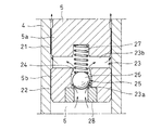
図1および図2に示すように、バルブスリーブ4内に位置するロッド5の下端部には、二つの大径部5a、5bが上下に設けられ、その上部大径部5aの外径は下部大径部5bの外径より小径とされている。
As shown in FIGS. 1 and 2, two large-
図2に示すように、上部大径部5aの外径面とバルブスリーブ4の内径面間には円環状のリーク隙間21が形成され、そのリーク隙間21が第1リークすきまとされている。一方、下部大径部5bとバルブスリーブ4の摺動面間には円環状のリーク隙間22が形成され、そのリーク隙間22が第2リークすきまとされている。
As shown in FIG. 2, an
第1リークすきま21と第2リークすきま22はすきま量の相違から、第1リークすきま21の流路抵抗が第2リークすきま22の流路抵抗より小さくなっている。第1リークすきま21および第2リークすきま22のそれぞれは、圧力室6内のオイルがそれぞれのリークすきま21、22に沿ってリークする際の粘性抵抗により圧力室6内に油圧ダンパ作用を生じさせるようになっている。
The
第1リークすきま21は、オイルのリークによって生じる油圧ダンパ作用によって図7(a)に示すエンジンの通常運転時におけるベルト54の張力変動を吸収可能とする大きさに設定されている。一方、第2リークすきま22は、図7(b)に示すスタータ・ジェネレータ52の駆動によるエンジン始動時にロッド5が急激に押し込まれることのない大きさに設定されている。
The
ロッド5の下端部には、圧力室6と第1リークすきま21を連通する連通路23が形成されている。連通路23は、ロッド5の下端面から軸方向に延びる軸方向孔部23aと、その軸方向孔部23aに交差して上部大径部5aの下部外径面で開口する径方向孔部23bとからなり、上記軸方向孔部23a内に第2チェックバルブ25が組み込まれている。
A
第2チェックバルブ25は、軸方向孔部23aに形成されたテーパ状のシート面24に対して接触離反自在とされたチェックボール26と、そのチェックボール26をシート面24から離反する方向に向けて付勢するスプリング27とからなり、軸方向孔部23aの下端部内にはチェックボール26を開放状態に保持するストッパリング28が圧入されている。
The
第2チェックバルブ25は、圧力室6内の圧力が高圧になるとチェックボール26がシート面24に接触して連通路23を閉鎖し、圧力室6と第1リークすきま21の連通を遮断するようになっている。この第2チェックバルブ25の設定圧は第1チェックバルブ17の設定圧より高く、第1チェックバルブ17の閉鎖後、圧力室6内の圧力がさらに上昇すると作動するようになっている。
The
バルブスリーブ4の内径面における上端部には環状溝29が形成され、その環状溝29内に止め輪30が組み込まれている。止め輪30の内周部はバルブスリーブ4の内径面より内方に位置し、その止め輪30の内周部に対する上部大径部5aの上端面の当接によってロッド5はバルブスリーブ4から抜け出るのが防止される。
An
実施の形態で示す油圧式オートテンショナは上記の構成からなり、図7(a)に示すアイドルストップ機構が搭載されたエンジンの補機駆動用ベルト伝動装置への組込みに際しては、シリンダ1の閉塞端に設けた連結片2をプーリアーム56に連結し、かつ、ばね座7の連結片9をエンジンブロックに連結して、そのプーリアーム56に調整力を付与する。
The hydraulic auto-tensioner shown in the embodiment has the above-described configuration, and when the engine equipped with the idle stop mechanism shown in FIG. The connecting
上記のようなベルト54の張力調整状態において、エンジンの通常運転状態において、補機53の負荷変動等によってベルト54の張力が変化し、上記ベルト54の張力が弱くなると、リターンスプリング8の押圧によりシリンダ1とロッド5が伸張する方向に相対移動してベルト54の弛みが吸収される。
In the tension adjustment state of the
ここで、シリンダ1とロッド5が伸張する方向に相対移動するとき、圧力室6内の圧力はリザーバ室14内の圧力より低くなるため、第1チェックバルブ17が開放する。このため、リザーバ室14内のオイルは油通路15から油溜り16を通って圧力室6内にスムーズに流れ、シリンダ1とロッド5は伸張する方向にスムーズに相対移動してベルト54の弛みを直ちに吸収する。
Here, when the
一方、ベルト54の張力が強くなると、ベルト54から油圧式オートテンショナのシリンダ1とロッド5を収縮させる方向の押込み力が負荷される。このとき、圧力室6内の圧力はリザーバ室14内の圧力より高くなるため、第1チェックバルブ17が閉鎖する。
On the other hand, when the tension of the
また、第2チェックバルブ25のチェックボール26は、第1チェックバルブ17が完全に閉鎖した後において、圧力室6内の圧力上昇により上昇動してストッパリング28から離反するが、シート面24に接触する位置まで上昇動することはなく、開放状態に保持される。
In addition, the
ストッパリング28に対するチェックボール26の移動により、圧力室6内のオイルは連通路23に流れ、第1リークすきま21を流通してリザーバ室14にリークし、上記第1リークすきま21を流動するオイルによって圧力室6内に油圧ダンパ力が発生する。その油圧ダンパ力により、油圧式オートテンショナに負荷される上記押込み力が緩衝される。
By the movement of the
このとき、第1リークすきま21は、エンジンの通常運転時におけるベルト54の張力変動を吸収可能な大きさに設定されているため、エンジンの通常運転時におけるベルト54の張力が高くなり過ぎることはなく、適正張力に保持される。
At this time, since the
一方、スタータ・ジェネレータ52の駆動によるエンジン始動時、ベルト54の張力は急激に大きくなってロッド5に対する押込み力が強くなり、圧力室6の圧力が急激に上昇する。このとき、第1チェックバルブ17は閉鎖すると共に、第2チェックバルブ25のチェックボール26が上昇して、図4に示すように、シート面24と接触し、閉鎖状態となる。
On the other hand, when the engine is started by driving the starter /
第2チェックバルブ25の閉鎖により、連通路23は圧力室6と第1リークすきま21の連通を遮断する状態となるため、圧力室6内のオイルは図4の矢印で示すように、第2リークすきま22から第1リークすきま21内に流れてリザーバ室14内にリークする。
By closing the
このとき、第2リークすきま22の流路抵抗は第1リークすきま21より大きいため、圧力室6内のオイルは第2リークすきま22内をゆっくりと流動する。このため、圧力室6での急激な圧力低下がなく、その圧力室6内の油圧ダンパ作用によってロッド5の押し込みが抑制され、ベルト54はクランクシャフト51を駆動するのに必要なベルト張力に保持され、ベルト54とプーリP1乃至P3間のスリップが防止される。
At this time, since the flow resistance of the
図5は、この発明に係る油圧式オートテンショナの他の実施の形態を示す。この実施の形態においては、ロッド5に圧力室6とリザーバ室14を連通するリーク通路31を設け、そのリーク通路31を、段付き孔からなる軸方向孔部32と、その軸方向孔部32の上端に連通してロッド5の外径面で開口する径方向孔部33で形成し、上記軸方向孔部32の中間孔部32a内に円柱状のコア34を組み込み、そのコア34の外径面と中間孔部32aの内径面間に形成された円環状のリーク隙間21を第1リークすきまとしている。
FIG. 5 shows another embodiment of the hydraulic auto tensioner according to the present invention. In this embodiment, the
また、軸方向孔部32の連通路としての下側大径孔部32b内に第2チェックバルブ25を組込み、その第2チェックバルブ25を、軸心上に弁孔36が形成された筒状の弁座35と、上記弁孔36の下端に形成されたテーパ状のシート面37に対して接触離反自在に設けられたチェックボール38と、そのチェックボール38をシート面37から離反する方向に付勢するスプリング39とで形成し、上記チェックボール38をロッド5の下側大径孔部32b内に圧入した連通孔41を有するキャップ状のリテーナ40によって開放状態に保持するようにしている。
Further, the
さらに、ロッド5を軸方向の全長にわたって同一外径の円筒状とし、その円筒状ロッド5をバルブスリーブ4の内周上端部に形成された小径孔部4a内に摺動自在に挿入して、その摺動面間に形成された円環状のリーク隙間22を第2リークすきまとしている。
Furthermore, the
さらに、また、ロッド5の下端部外周に環状溝42を設け、その環状溝42に止め輪43を取り付けて、小径孔部4aの下端面に対する止め輪43の当接によりロッド5を抜止めしている。
Further, an
他の構成は図1に示す油圧式オートテンショナと同一であるため、ここでは、バルブスリーブ4とロッド5の関係のみを示している。
Since the other structure is the same as that of the hydraulic auto tensioner shown in FIG. 1, only the relationship between the
図5に示す油圧式オートテンショナにおいては、図7(a)に示すエンジンの通常運転状態において、ベルト54からロッド5に押込み力が負荷された際、圧力室6内のオイルをリーク通路31および流路抵抗の小さな第1リークすきま21からリザーバ室14にリークさせ、第1リークすきま21を流れるオイルの粘性抵抗により圧力室6内に油圧ダンパ力を発生させて、その油圧ダンパ力により上記押込み力を緩衝し、ベルト54を適正張力に保持するようにしている。
In the hydraulic auto tensioner shown in FIG. 5, when a pushing force is applied from the
また、図7(b)に示すスタータ・ジェネレータ52の駆動によるエンジン始動時、ベルト54からロッド5に負荷される大きな押込み力により、第2チェックバルブ25を閉鎖させて、圧力室6内のオイルを流路抵抗の大きな第2リークすきま22からリザーバ室14にリークさせ、第2リークすきま22を流れるオイルの粘性抵抗により圧力室6内の急激な圧力の低下を抑制し、ロッド5が大きく押し込まれるのを防止して、ベルト54をクランクシャフト51を駆動するのに必要なベルト張力に保持している。
Further, when the engine is started by driving the starter /
図5では、コア34の外径面と中間孔部32aの内径面間に形成された円環状のリーク隙間21を第1リークすきまとしたが、図6に示すように、コア34の外径面に螺旋状のオリフィス21を形成し、そのオリフィス21を第1リークすきまとしてもよい。
In FIG. 5, the
1 シリンダ
4 バルブスリーブ
5 ロッド
6 圧力室
7 ばね座
8 リターンスプリング
14 リザーバ室
15 油通路
17 第1チェックバルブ
21 第1リークすきま
22 第2リークすきま
23 連通路
25 第2チェックバルブ
31 リーク通路
32 軸方向孔部
33 径方向孔部
34 コア
1
Claims (1)
前記リーク流路が、第1リークすきまと、前記第1リークすきまよりも流路抵抗が大きい第2のリークすきまからなり、前記ロッドには第1リークすきまと圧力室とを連通する連通路を設け、その連通路を前記第1チェックバルブより設定圧力が高くされた第2チェックバルブにより開閉自在とし、
前記ロッドとバルブスリーブの摺動面間にすきま量の異なる二つの円環状のリーク隙間を、すきま量の小さなリーク隙間が圧力室側に位置するよう軸方向に間隔をおいて設け、すきま量の大きなリーク隙間が第1リークすきまとされ、すきま量の小さなリーク隙間が第2リークすきまとされ、前記ロッドには第1リークすきまと前記圧力室とを連通する連通路を設け、その連通路に前記第2チェックバルブを組み込んだことを特徴とする油圧式オートテンショナ。
A valve sleeve protrudes from the bottom of the bottomed cylinder containing oil, and the lower end of the rod is slidably inserted into the valve sleeve to provide a pressure chamber in the valve sleeve. A return spring that urges the cylinder and rod in the extending direction is incorporated between the spring seat provided on the cylinder and the bottom surface of the cylinder, and a reservoir chamber is provided between the inner circumference of the cylinder and the outer circumference of the valve sleeve. Forms an oil passage communicating the lower portion of the reservoir chamber and the lower portion of the pressure chamber, and closes in the lower end portion of the valve sleeve when the pressure of the pressure chamber becomes higher than the pressure in the reservoir chamber. Provided with a first check valve that shuts off the communication of the pressure chamber, and when the pushing force is applied to the rod, the first check valve is closed to allow the oil in the pressure chamber to flow in a minute amount. In hydraulic auto-tensioner which is adapted to buffer the pushing force exerted on the rod by a hydraulic damper effect of the pressure chamber of the oil by leakage into the reservoir chamber from the flow path,
The leak flow path includes a first leak gap and a second leak gap having a larger flow path resistance than the first leak gap, and the rod has a communication path that connects the first leak gap and the pressure chamber. And the communication path can be opened and closed by a second check valve whose set pressure is higher than that of the first check valve .
Two annular leak gaps with different gaps are provided between the sliding surfaces of the rod and the valve sleeve so that the leak gap with a small gap is located on the pressure chamber side and spaced in the axial direction. The large leak gap is the first leak gap, the small leak gap is the second leak gap, and the rod is provided with a communication path that connects the first leak gap and the pressure chamber. A hydraulic auto tensioner incorporating the second check valve.
Priority Applications (2)
| Application Number | Priority Date | Filing Date | Title |
|---|---|---|---|
| JP2013163921A JP6257950B2 (en) | 2013-08-07 | 2013-08-07 | Hydraulic auto tensioner |
| PCT/JP2014/069307 WO2015019838A1 (en) | 2013-08-07 | 2014-07-22 | Pneumatic auto tensioner |
Applications Claiming Priority (1)
| Application Number | Priority Date | Filing Date | Title |
|---|---|---|---|
| JP2013163921A JP6257950B2 (en) | 2013-08-07 | 2013-08-07 | Hydraulic auto tensioner |
Related Child Applications (1)
| Application Number | Title | Priority Date | Filing Date |
|---|---|---|---|
| JP2017164366A Division JP6505794B2 (en) | 2017-08-29 | 2017-08-29 | Hydraulic auto tensioner |
Publications (3)
| Publication Number | Publication Date |
|---|---|
| JP2015031392A JP2015031392A (en) | 2015-02-16 |
| JP2015031392A5 JP2015031392A5 (en) | 2016-09-15 |
| JP6257950B2 true JP6257950B2 (en) | 2018-01-10 |
Family
ID=52461177
Family Applications (1)
| Application Number | Title | Priority Date | Filing Date |
|---|---|---|---|
| JP2013163921A Expired - Fee Related JP6257950B2 (en) | 2013-08-07 | 2013-08-07 | Hydraulic auto tensioner |
Country Status (2)
| Country | Link |
|---|---|
| JP (1) | JP6257950B2 (en) |
| WO (1) | WO2015019838A1 (en) |
Families Citing this family (4)
| Publication number | Priority date | Publication date | Assignee | Title |
|---|---|---|---|---|
| DE102014223229B4 (en) * | 2014-11-13 | 2016-07-21 | Schaeffler Technologies AG & Co. KG | Hydraulic belt tensioner |
| JP6463998B2 (en) * | 2015-03-11 | 2019-02-06 | Ntn株式会社 | Hydraulic auto tensioner |
| JP6513523B2 (en) * | 2015-07-28 | 2019-05-15 | Ntn株式会社 | Hydraulic auto tensioner |
| JP6599165B2 (en) * | 2015-08-11 | 2019-10-30 | Ntn株式会社 | Hydraulic auto tensioner |
Family Cites Families (4)
| Publication number | Priority date | Publication date | Assignee | Title |
|---|---|---|---|---|
| JPH11201245A (en) * | 1998-01-12 | 1999-07-27 | Ntn Corp | Chain tensioner |
| JP4072306B2 (en) * | 2000-08-09 | 2008-04-09 | Ntn株式会社 | Hydraulic chain tensioner |
| JP5112937B2 (en) * | 2008-04-22 | 2013-01-09 | Ntn株式会社 | Hydraulic auto tensioner |
| DE102010034290A1 (en) * | 2010-08-13 | 2012-02-16 | Schaeffler Technologies Gmbh & Co. Kg | Pressure-limited hydraulically damped clamping system |
-
2013
- 2013-08-07 JP JP2013163921A patent/JP6257950B2/en not_active Expired - Fee Related
-
2014
- 2014-07-22 WO PCT/JP2014/069307 patent/WO2015019838A1/en active Application Filing
Also Published As
| Publication number | Publication date |
|---|---|
| WO2015019838A1 (en) | 2015-02-12 |
| JP2015031392A (en) | 2015-02-16 |
Similar Documents
| Publication | Publication Date | Title |
|---|---|---|
| JP6182411B2 (en) | Hydraulic auto tensioner | |
| JP6463998B2 (en) | Hydraulic auto tensioner | |
| JP6257950B2 (en) | Hydraulic auto tensioner | |
| JP6263409B2 (en) | Hydraulic auto tensioner | |
| JP6807682B2 (en) | Hydraulic auto tensioner | |
| JP6560939B2 (en) | Hydraulic auto tensioner | |
| JP6250343B2 (en) | Hydraulic auto tensioner | |
| WO2015115555A1 (en) | Hydraulic automatic tensioner | |
| WO2017030051A1 (en) | Hydraulic automatic tensioner | |
| JP6505794B2 (en) | Hydraulic auto tensioner | |
| JP6153554B2 (en) | Hydraulic auto tensioner and belt drive | |
| WO2018168745A1 (en) | Hydraulic auto-tensioner | |
| JP5311226B2 (en) | Auto tensioner | |
| JP6234252B2 (en) | Hydraulic auto tensioner | |
| WO2017018311A1 (en) | Hydraulic automatic tensioner | |
| JP6153421B2 (en) | Hydraulic auto tensioner | |
| JP6581451B2 (en) | Hydraulic auto tensioner | |
| JP6599165B2 (en) | Hydraulic auto tensioner | |
| JP6773593B2 (en) | Hydraulic auto tensioner | |
| JP2017061961A (en) | Hydraulic automatic tensioner | |
| JP6664910B2 (en) | Hydraulic auto tensioner | |
| JP6602613B2 (en) | Hydraulic auto tensioner and method for manufacturing plunger for hydraulic auto tensioner | |
| JP2016145621A (en) | Hydraulic auto tensioner | |
| JP2017053447A (en) | Hydraulic automatic tensioner |
Legal Events
| Date | Code | Title | Description |
|---|---|---|---|
| A521 | Written amendment |
Free format text: JAPANESE INTERMEDIATE CODE: A523 Effective date: 20160726 |
|
| A621 | Written request for application examination |
Free format text: JAPANESE INTERMEDIATE CODE: A621 Effective date: 20160726 |
|
| A131 | Notification of reasons for refusal |
Free format text: JAPANESE INTERMEDIATE CODE: A131 Effective date: 20170704 |
|
| A521 | Written amendment |
Free format text: JAPANESE INTERMEDIATE CODE: A523 Effective date: 20170829 |
|
| TRDD | Decision of grant or rejection written | ||
| A01 | Written decision to grant a patent or to grant a registration (utility model) |
Free format text: JAPANESE INTERMEDIATE CODE: A01 Effective date: 20171107 |
|
| A61 | First payment of annual fees (during grant procedure) |
Free format text: JAPANESE INTERMEDIATE CODE: A61 Effective date: 20171206 |
|
| R150 | Certificate of patent or registration of utility model |
Ref document number: 6257950 Country of ref document: JP Free format text: JAPANESE INTERMEDIATE CODE: R150 |
|
| LAPS | Cancellation because of no payment of annual fees |